Table of Contents
Advertisement
Quick Links
Advertisement
Table of Contents

Subscribe to Our Youtube Channel
Related Manuals for YASKAWA MP3200iec


Summary of Contents for YASKAWA MP3200iec
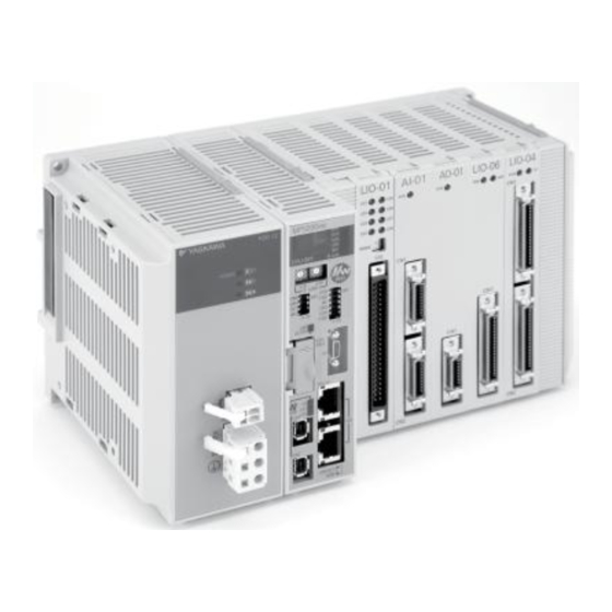
- Page 1 YASKAWA MP3200iec Machine Controller Hardware Manual Type: MP3200iec To properly use the product, read this manual thoroughly and retain for easy reference, inspection, and maintenance. Ensure the end user receives this manual. MANUAL NO. YAI-SIA-IEC-5...
-
Page 3: Table Of Contents
28. Cable Shielding, Segregation and Noise Immunity ......89 YASKAWA America, Inc. MP3200iec Hardware Manual YAI-SIA-IEC-5... - Page 4 Yaskawa. No patent liability is assumed with respect to the use of the information contained herein. Moreover, because Yaskawa is constantly striving to improve its high-quality products, the information contained in this manual is subject to change without notice.
-
Page 5: Definition Of Terms
Optional Modules. Base Unit Used to mount Optional Modules. The Basic Units are typically connected as shown in the following examples. Power CPU Unit Supply Unit Power CPU Unit Base Unit Supply Unit YASKAWA America, Inc. MP3200iec Hardware Manual YAI-SIA-IEC-5... -
Page 6: System Configuration Example
Front cover for unused slot 24-VDC power supply or AC MECHATROLINK-III power supply MECHATROLINK-III Cable SERVOPACK with MECHATROLINK-III Communications I/O Module with MECHATROLINK- Communications Servomotor Servomotor Servomotor Up to 62 stations, including I/O YASKAWA America, Inc. MP3200iec Hardware Manual YAI-SIA-IEC-5... -
Page 7: Component Part Numbers
MECHATROLINK-III CABLE, 30 M JEPMC-W6012-40-E MECHATROLINK-III CABLE, 40 M JEPMC-W6012-50-E MECHATROLINK-III CABLE, 50 M JEPMC-BA3001 Replacement Battery JEPMC-OP2300 Option Slot Cover Accessories JEPMC-OP3001 Replacement Power Supply Side Cover JEPMC-OP3002 Replacement Option Base Side Cover YASKAWA America, Inc. MP3200iec Hardware Manual YAI-SIA-IEC-5... -
Page 8: Power Supply Units
Appendix Indicator Yellow <1> Reduce the number of Optional Modules that are connected. : Lit, : Not lit. Note: YASKAWA America, Inc. MP3200iec Hardware Manual YAI-SIA-IEC-5... - Page 9 Pin Assignments: DC Power Supply Unit Pin No. Signal Label Description 24 VDC Power input wire for 24 VDC 0 VDC Power input wire for 0 VDC Connects to the frame ground. (Ground to 100 W max.) YASKAWA America, Inc. MP3200iec Hardware Manual YAI-SIA-IEC-5...
-
Page 10: Power Supply Unit Specifications
276 VAC 61 Hz: 0.5 mA max. Leakage Current 132 VAC 61 Hz: 0.25 mA max. 70% minimum (for rated input voltage and 65% minimum (for rated input voltage and rated Efficiency rated load) load) YASKAWA America, Inc. MP3200iec Hardware Manual YAI-SIA-IEC-5... - Page 11 Terminal RLY OUT RLYOUT External Power Supply AWG28 to AWG13 (0.08 to 2.6 mm Terminals (Twisted Pair) Connector Cable RLY OUT Connector Cable: AWG28 to AWG14 (0.08 to 2.0 mm Not supported. Swapping YASKAWA America, Inc. MP3200iec Hardware Manual YAI-SIA-IEC-5...
- Page 12 14.0 A iout (OCP activation) : Lit : Not lit. External Width: 60 mm, Height: 130 mm, Depth: 137 mm Dimensions Weight 350 g YASKAWA America, Inc. MP3200iec Hardware Manual YAI-SIA-IEC-5...
-
Page 13: Cpu Specifications
MP3200iec as Slave (Adapter) bytes, 3 instances of 128 bytes Any Global variable can be configured, requires OPC Server running read/write on PC Use the YDeviceComm firmware library to create a custom Custom Protocol communication protocol. YASKAWA America, Inc. MP3200iec Hardware Manual YAI-SIA-IEC-5... -
Page 14: Cpu External Appearance And Indicators
Indicator Name Color Meaning When Lit MECHATROLINK-III communications are established as a slave (i.e., the CONNECT Green command is ON). Green Port 1 is performing MECHATROLINK-III communications. Green Port 2 is performing MECHATROLINK-III communications. YASKAWA America, Inc. MP3200iec Hardware Manual YAI-SIA-IEC-5... -
Page 15: Base Unit Installation And Operating Conditions
8 Base Unit Installation and Operating Conditions Base Unit Installation and Operating Conditions This section describes the specifications of the MP3200iec Series Machine Controllers. Install the MP3200iec Series Controllers in an environment with the following conditions. Environmental Conditions Item... - Page 16 Radiation noise (FT noise): 1 kV min., for 1 minute Ground noise (impulse noise): ±1 kV min., for 10 minutes Electrostatic noise (conducted): ±4 kV min., 10 times Ground Information Ground to 100 max. Ω YASKAWA America, Inc. MP3200iec Hardware Manual YAI-SIA-IEC-5...
-
Page 17: Installation
9 Installation Installation You can use either of the following methods to install an MP3200iec Series Controller. • Screw mounting • DIN rail mounting Screw Mounting You can install the Unit by using the Screw Mounting Attachment. Note: You can install the Unit by using the Screw Mounting Attachment. - Page 18 2. Use screws to secure the 4 places shown in the following figure. Note: 1. Recommended screws: M4 x 14 mm min. 2. Use a screwdriver with a shaft that is at least 13 cm long. YASKAWA America, Inc. MP3200iec Hardware Manual YAI-SIA-IEC-5...
- Page 19 DIN Rail Mounting Carefully line up the DIN rail locks with the locking positions. Locking position Lock release position Note: Removal You can remove the Controller by reversing the order of the mounting procedure. YASKAWA America, Inc. MP3200iec Hardware Manual YAI-SIA-IEC-5...
- Page 20 • The left-side cap is marked with an L, and the right-side cap is marked with an R. 2. Connect the Power Supply Unit and the CPU Unit from left to right in this order. YASKAWA America, Inc. MP3200iec Hardware Manual YAI-SIA-IEC-5...
- Page 21 Optional Module firmly until it mates with the Mounting Base connectors in the Unit. The front of the Optional Module and the tabs will be aligned if the Optional Module has been installed properly. YASKAWA America, Inc. MP3200iec Hardware Manual YAI-SIA-IEC-5...
- Page 22 Note: Always create a backup before replacing or adding Optional Modules. Use the Web Server to save the Application program image as an Archive.Zip. 1. Turn OFF the power supply and disconnect all cables from the MP3200iec. 2. Remove the tool from Base Unit.
- Page 23 5. Hold the center of the tool, and turn it around the round knob while pushing it toward the back to disconnect the Module from the Mounting Base connectors. Then, pull the Module forward. YASKAWA America, Inc. MP3200iec Hardware Manual YAI-SIA-IEC-5...
- Page 24 Installing and Replacing the Battery in the CPU Battery Installation This Battery provides backup power for the SRAM data when the power supply to the MP3200iec Series CPU Unit is turned OFF. The Battery provides backup power for the following data. • Alarm history •...
- Page 25 5. Insert the Replacement Battery into the battery holder, and securely connect the lead connector of the Battery to the connector of the CPU Unit. Connector on CPU Unit Battery lead connector Battery Battery holder YASKAWA America, Inc. MP3200iec Hardware Manual YAI-SIA-IEC-5...
- Page 26 (on the side of the clamp) 2 battery leads Move the Battery. 8. Close the battery holder and confirm that the BAT indicator on the CPU Unit is not lit. This completes Battery replacement. YASKAWA America, Inc. MP3200iec Hardware Manual YAI-SIA-IEC-5...
-
Page 27: Dip Switch Settings
When ON, controller starts up in supervisor mode. In this mode MECHATROLINK III, PLC, Modbus/TCP and Ethernet/IP do not S2-1 start. The controller firmware can be updated, Normal Operation and clearing DOS FS alarms will repair the DOS FS. YASKAWA America, Inc. MP3200iec Hardware Manual YAI-SIA-IEC-5... - Page 28 USB thumb drive is not available in any other circumstances. Table B Firmware and User Project Loading LOAD Load user project from USB thumb drive. Install firmware and user project from USB thumb drive. YASKAWA America, Inc. MP3200iec Hardware Manual YAI-SIA-IEC-5...
-
Page 29: Led Indicators
• IP Address: If the TEST switch is ON, then the seven segment display outputs the IP address. • Firmware update: During programming the seven segment display outputs "FLASH...". When finished, the seven segment display outputs "donE". YASKAWA America, Inc. MP3200iec Hardware Manual YAI-SIA-IEC-5... -
Page 30: Self-Configuration
The MotionWorks IEC (Express or Pro) configuration can detect the configuration and provide the user with configuration choices. If a StartUp Configuration was already saved on the controller, the self-configure function will not allow new devices to be discovered. In this case, add them offline manually first. YASKAWA America, Inc. MP3200iec Hardware Manual YAI-SIA-IEC-5... -
Page 31: Mechatrolink-Iii Specifications
Hardware watchdog timer (PLD): 0 to 510 ms (register setting) Contacts ON for RUN status (RDY indicator lit), and OFF for WDT error status. The relay is built Relay Output into the Power Supply Unit. Backup Circuit Battery: BR-1/2AA (Panasonic), 3.0 V YASKAWA America, Inc. MP3200iec Hardware Manual YAI-SIA-IEC-5... -
Page 32: Mechatrolink-Iii Network Topologies
14 MECHATROLINK-III Network Topologies MECHATROLINK-III Network Topologies You can connect the MP3200iec Series Controller and drives or I/O with cascaded connections, star connections, or mixed cascaded/star network topologies. The following figures show examples of these types of network topologies. ... - Page 33 Note: 1. Terminating resistors are not required. 2. The maximum number of stations that you can connect with star connections depends on the communications cycle. Refer to Communications Cycle and the Number of Slave Stations on page YASKAWA America, Inc. MP3200iec Hardware Manual YAI-SIA-IEC-5...
- Page 34 Note: 1. Do not connect more than 32 stations to a single CPU Unit port, including the Hub Modules. 2. The maximum number of stations that you can connect with a mixed cascaded/star connections depends on the communications cycle. Refer to Communications Cycle and the Number of Slave Stations on page YASKAWA America, Inc. MP3200iec Hardware Manual YAI-SIA-IEC-5...
-
Page 35: Mechatrolink-Iii Synchronization Between Modules
NOTICE: If the SigmaWin+ is connected through a Machine Controller, the SigmaWin+ may not be usable if there are too many SERVOPACK stations connected. If this occurs, either connect the SigmaWin+ to the SERVOPACK (CN7) directly, or increase the communications cycle. YASKAWA America, Inc. MP3200iec Hardware Manual YAI-SIA-IEC-5... - Page 36 If asynchronous operation is set as a result of changing the communications cycle, an alarm will occur for the Servo axis and an I/O error will occur for the I/O station. If this happens, change the setting back to synchronized, save the settings to flash memory, and then cycle the power supply. YASKAWA America, Inc. MP3200iec Hardware Manual YAI-SIA-IEC-5...
-
Page 37: Devices Connectable Via Mechatrolink-Iii
SGDV- 25 I/O Modules The following table shows the module that is compatible with MECHATROLINK-III and can be connected to the controller. Model Details 64-point I/O Module JEPMC-MTD2310-E 24VDC, 64 inputs, 64 outputs YASKAWA America, Inc. MP3200iec Hardware Manual YAI-SIA-IEC-5... -
Page 38: Connecting The Rly Out Connector
Refer to the following figure for an example of connecting the RLY OUT connector. RLY OUT Power RLY OUT output supply Normal operation: ON Error: OFF 24-VDC 24 VDC power supply 0 VDC POWER Ground to 100 Ω max. YASKAWA America, Inc. MP3200iec Hardware Manual YAI-SIA-IEC-5... -
Page 39: Ethernet Connector Details
Lit: Connected at 100Mbps, or automatically negotiating 100M Green Unlit: Connected at 10Mbps Ethernet Cable For the Ethernet cable, use a twisted pair cable with RJ-45 connector. Yaskawa strongly recommends the use of shielded ethernet cables. Ethernet Category Remarks Type... - Page 40 100 m or less Cable Length between HUBs 100m or less 100 m or less Number of HUBs between Nodes Up to four Unlimited Connection Example 2 MP3200iec 10 Base-T (crossover cable, up to 100m) YASKAWA America, Inc. MP3200iec Hardware Manual YAI-SIA-IEC-5...
- Page 41 • If necessary, increase the number of communication retries. • Yaskawa strongly recommends shielded Ethernet cables. 3. Attach a ferrite core. Ethernet: Attach it to the communication port side and the external equipment side of the MP3200iec unit. MP3200iec SERVOPACK...
-
Page 42: Option Module - Ai-01 (Analog Input) Module
±0.1% (±10 mV) ±0.1% (±0.02 mA) Accuracy 0 to 55°C ±0.3% (±30 mV) ±0.3% (±0.06 mA) Input Conversion Time 1.4 msec Max CN1: Input connector Connectors CN2: Input connector LED Indicator RUN (green) YASKAWA America, Inc. MP3200iec Hardware Manual YAI-SIA-IEC-5... - Page 43 Applicable Cable: JEPMC-W6080-oo Standard Cable Model and External Appearance Model Length External Appearance (JEPMC-W6080-oo) JEPMC-W6080-05 0.5 m Marking tube (Label) NP JEPMC-W6080-05 26-core JEPMC-W6080-10 1.0 m Loose wires 150 mm JEPMC-W6080-30 3.0 m YASKAWA America, Inc. MP3200iec Hardware Manual YAI-SIA-IEC-5...
- Page 44 Mode switching terminal 1/5 Yellow Black – DN1/DN5 MDN1/MDN5 Mode switching terminal 1/5 Pink – – V2/V6 V2/V6 Voltage input 2/6 Pink Black – – G2V/G6V G2/G6 Ground 2/6 Yellow Black – – G2A/G6A YASKAWA America, Inc. MP3200iec Hardware Manual YAI-SIA-IEC-5...
- Page 45 Orange Black – – DN4/DN8 MDN4/MDN8 Mode switching terminal 4/8 DANGER Columns “Label on Marking Tube”, “Signal Name”, and “Function” display the values for connectors CN1 and CN2 in the format “CN1/CN2”, respectively. YASKAWA America, Inc. MP3200iec Hardware Manual YAI-SIA-IEC-5...
- Page 46 19 Option Module - AI-01 (Analog Input) Module Circuit Configuration Multiplexer Voltage input Current input Mode 256.5 Ground Voltage input Current input Mode 256.5 Photocoupler Ground Converter Voltage input Current input Mode +15V 256.5 DC/DC -15V Converter Ground Shell YASKAWA America, Inc. MP3200iec Hardware Manual YAI-SIA-IEC-5...
- Page 47 AI-01 module to external devices because the wiring distance varies between the AI-01 module and each external device. • Ground the cable shield between an external device and the relay terminal block on the external device side. YASKAWA America, Inc. MP3200iec Hardware Manual YAI-SIA-IEC-5...
-
Page 48: Option Module - Ao-01 (Analog Output) Module
Current Consumption 500 mA Max Dimensions 125 × 95 (H×D) Mass 90 g Indicators Indicator Indicator Status when Lit Status when not Lit Color Green Normal operation Operation stopped (no access from CPU) YASKAWA America, Inc. MP3200iec Hardware Manual YAI-SIA-IEC-5... - Page 49 Color Orange Analog Output 0 Gray Analog Output 1 Orange Black Ground 0 Gray Black A_Pulse+ White Pulse input ground Yellow White Black Yellow Black C-Phase latch input common (5V) 10~20 Twisted-pair cable YASKAWA America, Inc. MP3200iec Hardware Manual YAI-SIA-IEC-5...
- Page 50 • Ground the cable shield between the external devices and the junction terminal block by the external device side. YASKAWA America, Inc. MP3200iec Hardware Manual YAI-SIA-IEC-5...
-
Page 51: Option Module - Do-01 (Digital Output) Module
To ensure the circuit protection, provide a protective element such as fuse in each output as shown in the above diagram. YASKAWA America, Inc. MP3200iec Hardware Manual YAI-SIA-IEC-5... - Page 52 DO_11 DO_12 DO_13 DO_14 DO_15 OV_2 OV_2 +24V_3 OV_3 DO_16 DO_17 DO_18 DO_19 DO_20 DO_21 DO_22 DO_23 OV_3 OV_3 +24V_4 OV_4 DO_24 DO_25 DO_26 DO_27 DO_28 DO_29 DO_30 DO_31 OV_4 OV_4 N.C. N.C. YASKAWA America, Inc. MP3200iec Hardware Manual YAI-SIA-IEC-5...
- Page 53 — — — — Continuous 0V_4/8 Common ground 4/8 Pink — — — — Continuous Orange — 0V_1/5 Common ground 1/5 Gray — DO_01/33 Digital output 1/33 White — DO_03/35 Digital output 3/35 YASKAWA America, Inc. MP3200iec Hardware Manual YAI-SIA-IEC-5...
- Page 54 White ———————— DO_31/63 Digital output 31/63 Yellow ———————— 0V_4/8 Common ground 4/8 Pink ———————— DANGER Columns “Signal Name” and “Function” display the values for connectors CN1 and CN2 in the format “CN1/CN2” respectively. YASKAWA America, Inc. MP3200iec Hardware Manual YAI-SIA-IEC-5...
-
Page 55: Option Module - Lio-01/02 Module
LED Indicators and Switch Settings The LIO-02 Module status display LED indicators (LD1 to LD8) change based on the SW1 rotary switch settings. The following table shows the ON/OFF indicator display for digital input and digital output. YASKAWA America, Inc. MP3200iec Hardware Manual YAI-SIA-IEC-5... - Page 56 Encoder Input Phase-Z: 5V/12V photocoupler input, Max frequency: 500 kHz Latch input Position registration latch on phase-C or DI_01. Switches Rotary switch (SW1) Dimensions (mm) 125 x 95 (H x D) Mass 80 g YASKAWA America, Inc. MP3200iec Hardware Manual YAI-SIA-IEC-5...
- Page 57 Transistor, open collector source mode outputs Isolation Method Photocoupler Output Voltage +24VDC, ±20mv Output Current 100 mA Max Leakage Current When OFF 0.1 mA Max ON: 1 ms Max ON Time/OFF Time OFF: 1 ms Max YASKAWA America, Inc. MP3200iec Hardware Manual YAI-SIA-IEC-5...
- Page 58 Phase-Z: 5V/12V photocoupler input, Max frequency: 500 kHz Input Mode Phase-A/B, signed, incremental/decremental Position registration latch on phase-Z or DI_01. Latch Input Response time: 5 ms Max for phase-Z input; 60 ms Max for DI_01 input. YASKAWA America, Inc. MP3200iec Hardware Manual YAI-SIA-IEC-5...
- Page 59 Input common 0 Shield Frame ground Orange Black — Phase-A pulse (–) Gray Black — Phase-B pulse (–) Phase-C pulse White Black — PCL5 (-5V input) Phase-C pulse Yellow Black — PCL12 (-12V input) YASKAWA America, Inc. MP3200iec Hardware Manual YAI-SIA-IEC-5...
- Page 60 Module Cable Manufacturer FCN-360C048-E (cover), Fujitsu I/O Connector FCN-365P048-AU FCN-361J048-AU (jack) component Cables Name Model Number Length (JEPMC-W2061-oo) JEPMC-W2061-A5 0.5 m Cable for LIO- JEPMC-W2061-01 1.0 m 01/02 Modules JEPMC-W2061-03 3.0 m YASKAWA America, Inc. MP3200iec Hardware Manual YAI-SIA-IEC-5...
- Page 61 • The pins A5 and B5, and the pins A6 and B6 are internally connected. Connect them externally as well. YASKAWA America, Inc. MP3200iec Hardware Manual YAI-SIA-IEC-5...
- Page 62 Digital output DO_24V 24 VDC Fuse Fuse DO_01 DO_02 DO_03 DO_04 DO_05 DO_06 DO_07 External output DO_08 signals DO_09 DO_10 DO_11 DO_12 DO_13 DO_14 DO_15 DO_00 DO_COM DO_COM Load External Fuse YASKAWA America, Inc. MP3200iec Hardware Manual YAI-SIA-IEC-5...
-
Page 63: Option Module - Lio-04/05 Modules
Lit: One of the output protection fuses is blown. Not lit: All of the output protection fuses are normal. DANGER The burnout detection circuit will not function when there is no external 24V power supply. YASKAWA America, Inc. MP3200iec Hardware Manual YAI-SIA-IEC-5... - Page 64 Refer to the following characteristics graph for details. 32 outputs Digital Outputs 24VDC transistor open-collector outputs, sink mode outputs RUN (green) Indicators ERR (red) Dimensions (mm) 125 x 95 (H x D) Mass 80 g YASKAWA America, Inc. MP3200iec Hardware Manual YAI-SIA-IEC-5...
- Page 65 Digital Input Circuit (Sink Mode Input) Connection Example +24V DICOM Input register 5.6kΩ/ 0.5W DI_IN Photocoupler Digital Input Circuit (Source Mode Input) Connection Example +24V DICOM Input register 5.6kΩ/ 0.5W DI_IN Photocoupler YASKAWA America, Inc. MP3200iec Hardware Manual YAI-SIA-IEC-5...
- Page 66 LIO-04 Digital Output Circuit (Sink Mode Output) Connection Example +24V Photocoupler +24V Output register DO_OUT Transistor LIO-05 Digital Output Circuit (Source Mode Output) Connection Example +24V +24V Output Transistor register DO_OUT Photocoupler YASKAWA America, Inc. MP3200iec Hardware Manual YAI-SIA-IEC-5...
- Page 67 N.C. DO_20 DO_21 DO_22 DO_23 N.C. N.C. DO_24 DO_25 DO_26 DO_27 N.C. OV_4 +24V_4 N.C. DO_28 DO_29 DO_30 DO_31 N.C. OV_4 • P: Power supply input, I: Input signal, O: Open collector output YASKAWA America, Inc. MP3200iec Hardware Manual YAI-SIA-IEC-5...
- Page 68 Gray — — — Continuous DO_07/23 Digital output 7/23 White — — — Continuous N.C. Yellow — — — Continuous DO_09/25 Digital output 9/25 Pink — — — Continuous DO_11/27 Digital output 11/27 YASKAWA America, Inc. MP3200iec Hardware Manual YAI-SIA-IEC-5...
- Page 69 +24V_1 DO_04 DO_05 DO_06 DO_07 N.C. N.C. DO_08 DO_09 DO_10 DO_11 N.C. OV_2 +24V_2 +24V_2 DO_12 DO_13 DO_14 DO_15 N.C. N.C. • P: Power supply input, I: Input signal, O: Open collector output YASKAWA America, Inc. MP3200iec Hardware Manual YAI-SIA-IEC-5...
- Page 70 — — — — Continuous DO_14/30 Digital output 14/30 Pink — — — — Continuous N.C. Orange — N.C. Gray — DI_01/17 Digital input 1/17 White — DI_03/19 Digital input 3/19 Yellow — DI_05/21 Digital input 5/21 YASKAWA America, Inc. MP3200iec Hardware Manual YAI-SIA-IEC-5...
- Page 71 Digital output 13/29 Yellow ———————— DO_15/31 Digital output 15/31 Pink ———————— N.C. DANGER Columns “Signal Name”, “I/O”, and “Function” display the values for connectors CN1 and CN2 in the format “CN1/ CN2” respectively. YASKAWA America, Inc. MP3200iec Hardware Manual YAI-SIA-IEC-5...
- Page 72 • Check the polarity of the external power supply when wiring. An adverse connection may cause a load malfunction. • The pins 39 and 43 and the pins 46 and 50 are internally connected. Connect them externally as well. YASKAWA America, Inc. MP3200iec Hardware Manual YAI-SIA-IEC-5...
- Page 73 • Check the polarity of the external power supply when wiring. An adverse connection may cause a load malfunction. • The pins 39 and 32 and the pins 46 and 50 are internally connected. Connect them externally as well. YASKAWA America, Inc. MP3200iec Hardware Manual YAI-SIA-IEC-5...
- Page 74 Output 12 Output 13 Load Output 14 External Fuse Output 15 (Installed by customer) DANGER Check the polarity of the external power supply when wiring. An adverse connection may cause a load malfunction. YASKAWA America, Inc. MP3200iec Hardware Manual YAI-SIA-IEC-5...
- Page 75 Load Output 28 External Fuse Output 29 (Installed by customer) Output 30 Output 31 DANGER Check the polarity of the external power supply when wiring. An adverse connection may cause a load malfunction. YASKAWA America, Inc. MP3200iec Hardware Manual YAI-SIA-IEC-5...
-
Page 76: Option Module - Lio-06 Module
Status when Lit Staus when OFF Green Normal Stopped. (No access by CPU) Fault Normal operation The ALM light indicates the following conditions • Fuse fault • ASIC error • A-phase disconnect • B-phase disconnect YASKAWA America, Inc. MP3200iec Hardware Manual YAI-SIA-IEC-5... - Page 77 ±5mA Output Delay Time 1.2ms (Time of change from -10+10V) DANGER The time constant shows the characteristics according to the input filter equivalent to the time to reach 0.632 × the input voltage. YASKAWA America, Inc. MP3200iec Hardware Manual YAI-SIA-IEC-5...
- Page 78 ON=0.5ms Max/OFF=0.5ms Max Number of Commons DI_01 is used together with the position registration latch input, and when enabled, Other Functions the position registration latch input latches with the pulse encoder when SI_01 is "ON". YASKAWA America, Inc. MP3200iec Hardware Manual YAI-SIA-IEC-5...
- Page 79 The fuses are not for circuit protection. They are for fire protection at output shorts. A fuse Protection Circuit should be attached outside each output when a protective circuit is necessary. Fuse Rating Error Detection Blown fuse detection YASKAWA America, Inc. MP3200iec Hardware Manual YAI-SIA-IEC-5...
- Page 80 The following shows an analog input response chart and input characteristics diagram for the LIO-06 module. Input Characteristics Response Chart Analog Input Value Input Register Value -10.5V -32768 -10.0V -31276 -5.0V -15638 0.0V +5.0V 15638 +10.0V 31276 +10.5V 32767 • Minimum linearity of +10.0V cannot be assured. YASKAWA America, Inc. MP3200iec Hardware Manual YAI-SIA-IEC-5...
- Page 81 Maximum Permissible Load Current ±5mA Resolution 16-Bit (-31276 to +31276) 25ºC ±0.1% (±10mV) Absolute 0 to 55ºC ±0.3% (±30mV) Output Delay Time 1.2ms (Time of change from -10+10V) Analog Output Circuit Connection Example YASKAWA America, Inc. MP3200iec Hardware Manual YAI-SIA-IEC-5...
- Page 82 C-Phase: 5V/12V/24V photocoupler input, max frequency 500kHz Input Mode A/B-phase, code, UP/DOWN counter, pulse, and direction Position registration latch with C-Phase of DI_01 Latch Input Response Time: Max 5s during C-Phase input, During DI_01 Input: Max 60s YASKAWA America, Inc. MP3200iec Hardware Manual YAI-SIA-IEC-5...
- Page 83 One-touch lock type Standard Cable JEPMC-W2064-oo-E Pigtail Standard Cable Model and External Appearance Name Model Length External Appearance (JEPMC-W2064-oo-E) JEPMC-W2064-A5-E 0.5 m Cable for LIO-06 50-core Module JEPMC-W2064-01-E Loose wires (Single loose wire) JEPMC-W2064-03-E YASKAWA America, Inc. MP3200iec Hardware Manual YAI-SIA-IEC-5...
- Page 84 — — — Continuous N.C. Yellow — — — Continuous N.C. Pink — — — Continuous DO_24V Digital output 24V Power Supply Orange ———————— DO_01 Digital Output 1 Gray ———————— DO_03 Digital Output 3 YASKAWA America, Inc. MP3200iec Hardware Manual YAI-SIA-IEC-5...
- Page 85 External Fuse External Fuse (Installed by customer) (Installed by customer) Connector Shell) DANGER The cable shield between the external equipment and the junction terminal block should be installed on the external device side. YASKAWA America, Inc. MP3200iec Hardware Manual YAI-SIA-IEC-5...
-
Page 86: Terminal Block Kit Cbk-U-Mp2A-Xx
Output 9 DI_01 input) DO_08 Output 8 DI_00 Input 0 DO_07 Output 7 DI_COM0 Input common 0 DO_06 Output 6 DI_COM1 Input common 1 DO_05 Output 5 Frame ground DO_04 Output 4 Frame ground YASKAWA America, Inc. MP3200iec Hardware Manual YAI-SIA-IEC-5... -
Page 87: Terminal Block Kit Cbk-U-Mp2B-Xx
Digital output 13 DO_29 Digital output 29 DO_05 Digital output 5 Digital output 7 (shared with position agreement DO_15 Digital output 15 DO_31 Digital output 31 DO_07 'COIN' signal) DO_GND Digital output 0V common YASKAWA America, Inc. MP3200iec Hardware Manual YAI-SIA-IEC-5... -
Page 88: Terminal Block Kit Cbk-U-Mp2C-Xx
24V power supply 3 +24V_5 24V power supply 5 +24V_7 24V power supply 7 +24V_1 24V power supply 1 +24V_3 24V power supply 3 +24V_5 24V power supply 5 +24V_7 24V power supply 7 YASKAWA America, Inc. MP3200iec Hardware Manual YAI-SIA-IEC-5... -
Page 89: Cable Shielding, Segregation And Noise Immunity
Wrong Shields tied Terminal Block back at device Connector Case WRONG Shield grounded at more than one point. Shields tied Terminal Block back at device Connector Case WRONG Shields of field cables ungrounded YASKAWA America, Inc. MP3200iec Hardware Manual YAI-SIA-IEC-5... - Page 90 The revision dates and the numbers of the revised manuals appear on the bottom of the back cover. Revision Date of Publication Section Revised Content Number January 2013 First Edition. December 2017 A-1-1 2,25 Removal of unsupported 218IF Communication Card. YASKAWA America, Inc. MP3200iec Hardware Manual YAI-SIA-IEC-5...
- Page 92 Phone 81-4-2962-5151 Fax 81-4-2962-6138 YASKAWA AMERICA, INC. 2121 Norman Dr ive South, Waukegan, IL 60085, U.S.A. Phone (800) YASKAWA (800-927-5292) or 1-847-887-7000 Fa x 1-847-887-7310 YASKAWA ELETRICO DO BRASIL LTDA. Avenida Fa gundes Filho , 620 Sao Paulo-SP CEP 04304-000, Brazil...
Need help?
Do you have a question about the MP3200iec and is the answer not in the manual?
Questions and answers