Sign In
Upload
Manuals
Brands
Toho Electronics Manuals
Recording Equipment
TRM-10C
Toho Electronics TRM-10C Manuals
Manuals and User Guides for Toho Electronics TRM-10C. We have
3
Toho Electronics TRM-10C manuals available for free PDF download: Instruction Manual
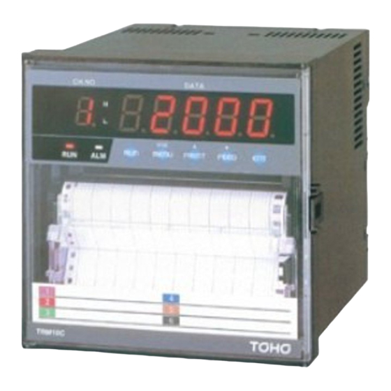
Toho Electronics TRM-10C Instruction Manual (129 pages)
HYBRID PEN TYPE RECORDER
Brand:
Toho Electronics
| Category:
Measuring Instruments
| Size: 2 MB
Table of Contents
Table of Contents
5
1 Introduction
7
Checking the Accessories
7
Checking the Type and Specifications
9
Temporary Storage
10
Indication Card
10
2 Construction
11
Appearance
11
Display Screen and Operation Keys
12
Display Screen
12
Operation Keys
13
3 Installation
14
Outside Dimensions Drawing and Panel Cutting Dimensions
14
Mounting to the Panel
15
Procedure for Mounting to the Panel
15
Mounting to the Panel in Compliance with the IP65
16
4 Wiring
17
Terminal Layout and Power Wiring
17
Terminal Layout
17
Power Wiring
17
Wiring Procedure
18
Input Wiring
19
Wiring Procedure
20
DI/Alarm Output Wiring (Option)
22
DI/Alarm Output Wiring Example
23
Alarm Output Wiring Procedure
24
DI Wiring Procedure
24
Communication Wiring
25
RS-232C Wiring
25
Wiring
25
5 Preparations for Operation
26
Setting the Chart Paper
26
Setting the Cartridge Pen
33
Setting the Ribbon Cassette
35
6 Operation
40
Status after Initial Screen
40
Recording
41
Recording Colors
41
Printing Color
41
Pen Gap
41
Gaps between Pens and Printer
41
Print Gap Correction
42
How to Record
42
Starting/Stopping Recording Operation
42
Feed the Chart Paper
42
Print Sample
43
Digital Print
44
Manual Print
44
List Print
45
Engineering List Print
47
Record Start/End Print
49
DI Manual Print(Option)
49
DI Date/Time Print(Option)
49
DI Comment Print(Option)
50
Changing the Display
51
Auto Display
51
Manual Display
51
Date Display
51
Time Display
51
Display off
51
7 Device Setting
52
Setting the Setup Mode
52
Setting the Range
55
Setting Method
55
(Current/Voltage) (Thermocouple)
56
Resistance Temperature Detector
56
Scaling
58
Square Root
60
Decade
62
(Difference) (Sum), (Average)
64
Skip
65
Setting the Alarm
66
Setting the Unit
68
Character Code Table
69
Setting the Chart Speed
70
Setting the Date and Time
71
Copying the Setting Data
72
Setting Other Functions
73
Zone Recording
74
Partial Compression/Expansion
75
Digital Print
76
Tag
77
Comment Words
78
Setting the Engineering Mode
79
Alarm Hysteresis
82
Burnout ON/OFF
82
Channel Offset
83
Reference Junction Compensation
83
Digital Filter
85
Settings Related to Recording
85
Recording Start/Stop Trigger Setting
85
Tag/Channel Print Selection
86
Alarm Print ON/OFF
86
Logging Print ON/OFF
87
Print Gap Correction ON/OFF
88
Record Start/End Print OFF/SYNC/ASYNC
88
Setting the Communication Function
89
Initializing the Setup Data
90
DI Functions
90
Temperture Unit
91
Point Calibration
91
Data Calibration
92
Terminating the Engineering Mode
95
8 Communications
96
General Description
96
General Description of Functions
96
Transmission Specifications
96
Original Protocol
97
Data Construction
97
Opening/Closing the Link
97
Outputting the Process Variable Data
98
Outputting the Unit and Decimal Point Position Data
101
Outputting the Status
102
Data Reception Example
103
Modbus RTU Protocol
104
Data Construction
104
Function Codes
104
Error Response
104
Reading from the Input Register Area
105
Reading from or Writing to the Holding Register Area
108
9 Maintenance
109
Inspection
109
Cleaning
109
Replacing Consumables
110
Adjusting the Pen Recording Position
110
(Point Calibration)
110
Calibration (Data Calibration)
110
Calibration of Voltage
111
Calibration of Resistance Temperature Detector
111
Calibration of Reference Junction Compensation
112
10 Troubleshooting
113
Trouble Items
113
When the Recorder Does Not Work at All
113
When There Is a Big Error
114
When the Pen Recording Deflected
114
When Prints Nothing
115
When Printing Is Faint
115
When the Chart Paper Is Not Fed at All
116
When the Chart Paper Is Not Fed Properly
116
Self Diagnostics Function (ERROR)
117
Self Diagnostic Items
117
Error Display
118
11 Specifications
119
Common Specifications
119
Input Signal
119
Performance and Characteristics
119
Structure
120
Power Source
120
Normal Operating Conditions
120
Alarm (Relay Output Is Optional)
121
Safety Standard and EMI Standard
121
DI Function (Option)
121
Paper-Empty Detecting Function (Option)
121
Standard Setting Specifications
122
Measurement Range
122
The Accuracy at the Computation
125
Scaling
125
Square Root Computation
125
Decade
126
Difference, Sum, and Average
126
Individual Specifications
127
Standard Functions
128
Standard Setting Functions
129
Optional Functions
129
Remote Function of DI
129
Alarm Board
129
Communication Unit
129
Advertisement
Toho Electronics TRM-10C Instruction Manual (119 pages)
HYBRID RECORDER(MULTIPOINT TYPE RECORDER)
Brand:
Toho Electronics
| Category:
Measuring Instruments
| Size: 2 MB
Table of Contents
Table of Contents
5
Introduction
7
Hybrid Recorder
7
Checking the Accessories
7
Checking the Type and Specifications
8
Temporary Storage
9
Indication Card
9
Construction
10
Appearance
10
Display Screen and Operation Keys
11
Display Screen
11
Operation Keys
12
Installation
13
Outside Dimensions Drawing and Panel Cutting Dimensions
13
Mounting to the Panel
14
Procedure for Mounting to the Panel
14
Mounting to the Panel in Compliance with the IP65
15
Wiring
16
Terminal Layout and Power Wiring
16
Terminal Layout
16
Power Wiring
16
Wiring Procedure
17
Input Wiring
18
Wiring Procedure
19
DI/Alarm Output Wiring (Option)
21
DI/Alarm Output Wiring Example
21
Alarm Output Wiring Procedure
22
DI Wiring Procedure
22
Communication Wiring
23
RS-232C Wiring
23
Wiring
23
Preparations for Operation
24
Setting the Chart Paper
24
Setting the Ribbon Cassette
30
Operation
32
Status after Initial Screen
32
Recording
33
Recording Colors
33
How to Record
33
Starting/Stopping Recording Operation
33
Feed the Chart Paper
33
Print Sample
34
Digital Print
35
Manual Print
35
List Print
36
Engineering List Print
38
Record Start/End Print
40
DI Manual Print
40
DI Date/Time Print
40
DI Comment Print
41
Changing the Display
42
Auto Display
42
Manual Display
42
Date Display
42
Time Display
42
Display off
42
Device Setting
43
Setting the Setup Mode
43
Setting the Range
46
Setting Method
46
(Current/Voltage), (Thermocouple)
47
(Resistance Temperature Detector)
47
(Scaling)
49
(Square Root)
51
(Decade)
53
(Difference), (Sum)
55
(Average)
55
(Skip)
56
Setting the Alarm
57
Setting the Unit
59
Character Code Table
60
Setting the Chart Speed
61
Setting the Date and Time
62
Copying the Setting Data
63
Setting Other Functions
64
(Printing Cycle)
65
(Zone Recording)
65
(Partial Compression/Expansion)
66
(Digital Print)
67
(Tag)
68
(Comment Words)
69
Setting the Engineering Mode
70
Alarm Hysteresis
73
Burnout ON/OFF
73
Channel Offset
73
Reference Junction Compensation
74
Changing the Printing Color
75
Settings Related to Recording
76
Recording Start/Stop Trigger Setting
76
Tag/Channel Print Selection
76
Alarm Print ON/OFF
77
Logging Print ON/OFF
77
Scale Print ON/OFF
78
Logging Print Synchronous/Asynchronous
79
Setting the Communication Function
79
Initializing the Setup Data
80
DI Functions
80
Temperature Unit
81
Point Calibration
81
Data Calibration
83
Terminating the Engineering Mode
85
Communications
86
General Description
86
General Description of Functions
86
Transmission Specifications
86
Original Protocol
87
Data Construction
87
Opening/Closing the Link
87
Outputting the Process Variable Data
88
Outputting the Unit and Decimal Point Position Data
91
Outputting the Status
92
Data Reception Example
93
Modbus RTU Protocol
94
Data Construction
94
Function Codes
94
Error Response
94
Reading from the Input Register Area
95
Reading from or Writing to the Holding Register Area
98
Maintenance
99
Inspection
99
Cleaning
99
Replacing Consumables
100
Adjust Dot Printing Position (Point Calibration)
100
Calibration (Data Calibration)
100
Calibration of Voltage
101
Calibration of Resistance Temperature Detector
101
Calibration of Reference Junction Compensation
102
Troubleshooting
103
Trouble Items
103
When the Recorder Dose Not Work at All
103
When There Is a Big Error
104
When the Trend Recording Deflected
104
When Records Nothing
105
When Recording Is Faint
105
When the Chart Paper Is Not Fed at All
106
When the Chart Paper Is Not Fed Properly
106
Self Diagnostics Function (ERROR)
107
Self Diagnostic Items
107
Error Display
108
Specifications
109
Common Specifications
109
Input Signal
109
Performance and Characteristics
109
Structure
110
Power Source
110
Normal Operating Conditions
110
Alarm (Relay Output Is Optional)
111
Safety Standard and EMI Standard
111
DI Function (Option)
111
Paper-Empty Detecting Function (Option)
111
Standard Setting Specifications
112
Measurement Range
112
The Accuracy at the Computation
115
Scaling
115
Square Root Computation
115
Decade
116
Difference, Sum, and Average
116
Individual Specifications
117
Standard Functions
118
Standard Setting Functions
119
Optional Functions
119
Remote Function of DI
119
Alarm Board
119
Communication Unit
119
Toho Electronics TRM-10C Instruction Manual (111 pages)
HYBRID RECORDER (MULTIPOINT TYPE RECORDER)
Brand:
Toho Electronics
| Category:
Recording Equipment
| Size: 0 MB
Table of Contents
1 Introduction
4
Table of Contents
5
Checking the Accessories
7
Checking the Type and Specifications
8
Indication Card
9
Temporary Storage
9
2 Construction
10
Appearance
10
Display Screen and Operation Keys
11
Display Screen
11
Operation Keys
12
3 Installation
13
Outside Dimensions Drawing and Panel Cutting Dimensions
13
Mounting to the Panel
14
Procedure for Mounting to the Panel
14
Mounting to the Panel in Compliance with the IP65
15
4 Wiring
16
Terminal Layout and Power Wiring
16
Terminal Layout
16
Power Wiring
16
Wiring Procedure
17
Input Wiring
18
Wiring Procedure
19
DI/Alarm Output Wiring (Option)
21
DI/Alarm Output Wiring Example
21
Alarm Output Wiring Procedure
22
DI Wiring Procedure
22
Communication Wiring
23
RS-232C Wiring
23
Wiring
23
5 Preparations for Operation
24
Setting the Chart Paper
24
Setting the Ribbon Cassette
30
6 Operation
32
Status after Initial Screen
32
Recording
33
Recording Colors
33
How to Record
33
Starting/Stopping Recording Operation
33
Feed the Chart Paper
33
Print Sample
34
Digital Print
35
Manual Print
35
List Print
36
Engineering List Print
38
Changing the Display
40
Auto Display
40
Manual Display
40
Date Display
40
Time Display
40
Display off
40
7 Device Setting
41
Setting the Setup Mode
41
Setting the Range
44
Setting Method
44
(Current/Voltage), (Thermocouple), (Resistance Temperature Detector)
45
(Scaling)
47
(Square Root)
49
(Decade)
51
(Difference)• C (Sum)• C (Average)
53
(Skip)
54
Setting the Alarm
55
Setting the Unit
57
Character Code Table
58
Setting the Chart Speed
59
Setting the Date and Time
60
Copying the Setting Data
61
Setting Other Functions
62
(Printing Cycle)
63
(Zone Recording)
63
(Partial Compression/Expansion)
64
(Digital Print)
65
(Tag)
66
(Comment Words)
67
Setting the Engineering Mode
68
Alarm Hysteresis
71
Burnout ON/OFF
71
Channel Offset
71
Reference Junction Compensation
72
Changing the Printing Color
73
Settings Related to Recording
74
Recording Start/Stop Trigger Setting
74
Tag/Channel Print Selection
74
Alarm Print ON/OFF
75
Logging Print ON/OFF
75
Scale Print ON/OFF
76
Logging Print Synchronous/Asynchronous
76
Setting the Communication Function
77
Initializing the Setup Data
77
DI Functions
78
Temperature Unit
78
Point Calibration
79
Data Calibration
80
Terminating the Engineering Mode
82
8 Communications
83
General Description
83
General Description of Functions
83
Transmission Specifications
83
Data Construction
83
Opening/Closing the Link
84
Open Command
84
Close Command
84
Outputting the Process Variable Data
85
Specifying the Process Variable Data Output
85
Updating the Data
85
Specifying the Process Variable Data Output Order (at BINARY Mode Output)
85
Outputting the Data
85
Process Variable Data Transmission Format (ASCII)
86
Process Variable Data Transmission Format (BINARY)
87
Outputting the Unit and Decimal Point Position Data
88
Specifying the Unit and Decimal Point Position Data Output
88
Updating the Data
88
Outputting the Data
88
Data Format
88
Outputting the Status
89
Status Output Command
89
Status Output
89
Data Reception Example
90
9 Maintenance
91
Inspection
91
Cleaning
91
Replacing Consumables
92
Adjust Dot Printing Position (Point Calibration)
92
Calibration (Data Calibration)
92
Calibration of Voltage
93
Calibration of Resistance Temperature Detector
93
Calibration of Reference Junction Compensation
94
10 Troubleshooting
95
Trouble Items
95
When the Recorder Dose Not Work at All
95
When There Is a Big Error
96
When the Trend Recording Deflected
96
When Records Nothing
97
When Recording Is Faint
97
When the Chart Paper Is Not Fed at All
98
When the Chart Paper Is Not Fed Properly
98
Self Diagnostics Function (ERROR)
99
Self Diagnostic Items
99
Error Display
100
11 Specifications
101
Common Specifications
101
Input Signal
101
Performance and Characteristics
101
Structure
102
Power Source
102
Normal Operating Conditions
102
Alarm (Relay Output Is Optional)
103
Safety Standard and EMI Standard
103
DI Function (Option)
103
Paper-Empty Detecting Function (Option)
103
Standard Setting Specifications
104
Measurement Range
104
The Accuracy at the Computation
107
Scaling
107
Square Root Computation
107
Decade
108
Difference, Sum, and Average
108
Individual Specifications
109
Standard Functions
110
Standard Setting Functions
111
Optional Functions
111
Remote Function of DI
111
Alarm Board
111
Communication Unit
111
Advertisement
Advertisement
Related Products
Toho Electronics TRM-00J
Toho Electronics TRM20A
Toho Electronics TTM-200 Series
Toho Electronics TTM-304
Toho Electronics TTM-305
Toho Electronics TTM-309
Toho Electronics TTM-339
Toho Electronics TTX-800
Toho Electronics TTM-210 Series
Toho Electronics TTM-P4W Series
Toho Electronics Categories
Controller
Temperature Controller
Measuring Instruments
Dehumidifier
Thermometer
More Toho Electronics Manuals
Login
Sign In
OR
Sign in with Facebook
Sign in with Google
Upload manual
Upload from disk
Upload from URL