YASKAWA S-V Series User Manual
Ac servo drives indexer module
Hide thumbs
Also See for S-V Series:
- User manual (311 pages) ,
- Safety precautions (33 pages) ,
- User manual (320 pages)
Table of Contents
Advertisement
Quick Links
AC Servo Drives
V
-
Series/
V
-
Series for
Large-Capacity Models
USER'S MANUAL
INDEXER Module
Model: SGDV-OCA03A
MANUAL NO. SIEP C720829 02H
Overview
Specifications
SERVOPACK Installation
Wiring and Connection
Parameter Setting and Functions
Program Table
Serial Command Communications
Operation of Digital Operator
Troubleshooting
Appendix
1
2
3
4
5
6
7
8
9
10
Advertisement
Table of Contents
Troubleshooting

Related Manuals for YASKAWA S-V Series


Summary of Contents for YASKAWA S-V Series
- Page 1 AC Servo Drives Series/ Series for Large-Capacity Models USER'S MANUAL INDEXER Module Model: SGDV-OCA03A Overview Specifications SERVOPACK Installation Wiring and Connection Parameter Setting and Functions Program Table Serial Command Communications Operation of Digital Operator Troubleshooting Appendix MANUAL NO. SIEP C720829 02H...
- Page 2 Yaskawa. No patent liability is assumed with respect to the use of the information contained herein. Moreover, because Yaskawa is con- stantly striving to improve its high-quality products, the information contained in this manual is subject to change without notice.
-
Page 3: About This Manual
About this Manual This manual describes information required for designing, trial operating, adjusting and maintaining the INDEXER Module for Σ-V Series and Large-Capacity Σ-V Series SERVOPACKs. Be sure to refer to this manual and perform design and maintenance to select devices correctly. Keep this manual in a location where it can be accessed for reference whenever required. - Page 4 • Parameter Notation The following two types of notations are used for parameter digit places and settings. Example Notation Example for Pn000 Pn000 Digit Notation Set Value Notation Meaning Notation Method Notation Method Meaning Indicates that digit 1 of the Indicates digit 1 Pn000.0 = x Digit 1...
- Page 5 (cont’d) Selecting Trial Maintenance Models and Ratings and Designing Panels and Trial Operation Name Peripheral Specifications the System Wiring Operation and Servo Inspection Devices Adjustment Σ-V Series User's Manual For Use with Large- Capacity Models Design and Maintenance Rotational Motor (SIEP S800000 98) Σ-V Series User’s Manual...
-
Page 6: Safety Precautions
Safety Precautions These safety precautions are very important. Read them before performing any procedures such as checking products on delivery, storage and transportation, installation, wiring, operation and inspection, or disposal. Be sure to always observe these precautions thoroughly. WARNING • Never touch any rotating motor parts while the motor is running. Failure to observe this warning may result in injury. - Page 7 Storage and Transportation CAUTION • Do not store or install the product in the following locations. Failure to observe this caution may result in fire, electric shock, or damage to the product. • Locations subject to direct sunlight • Locations subject to ambient operating temperatures outside the range specified in the storage/installation temperature conditions •...
- Page 8 Wiring CAUTION • Be sure to wire correctly and securely. Failure to observe this caution may result in motor overrun, injury, or malfunction. • Do not connect a commercial power supply to the U, V, or W terminals for the servomotor connec- tion.
- Page 9 Operation CAUTION • Always use the servomotor and SERVOPACK in one of the specified combinations. Failure to observe this caution may result in fire or malfunction. • Conduct trial operation on the servomotor alone with the motor shaft disconnected from the machine to avoid accidents.
- Page 10 • The drawings presented in this manual are typical examples and may not match the product you received. • If the manual must be ordered due to loss or damage, inform your nearest Yaskawa representative or one of the offices listed on the back of this manual.
-
Page 11: Warranty
6. Events for which Yaskawa is not responsible, such as natural or human-made disasters (2) Limitations of Liability 1. Yaskawa shall in no event be responsible for any damage or loss of opportunity to the customer that arises due to failure of the delivered product. - Page 12 2. The customer must confirm that the Yaskawa product is suitable for the systems, machines, and equipment used by the customer. 3. Consult with Yaskawa to determine whether use in the following applications is acceptable. If use in the application is acceptable, use the product with extra allowance in ratings and specifications, and provide safety measures to minimize hazards in the event of failure.
-
Page 13: Harmonized Standards
Harmonized Standards North American Safety Standards (UL) UL Standards Model (UL File No.) SERVOPACK SGDV UL508C (E147823) Note: Applicable when the INDEXER Module is attached to the SERVOPACKs for use with the command option attachable type. EU Directives Model EU Directives Harmonized Standards... - Page 14 Safety Standards Model Safety Standards Standards EN ISO13849-1: 2015 Safety of Machinery IEC 60204-1 IEC 61508 series SERVOPACK SGDV Functional Safety IEC 62061 IEC 61800-5-2 IEC 61326-3-1 Note: Applicable when the INDEXER Module is attached to the SERVOPACKs for use with the command option attachable type.
-
Page 15: Table Of Contents
Contents About this Manual ............iii Safety Precautions. - Page 16 5.3.1 Servo ON Signal (/S-ON) ..........5-5 5.3.2 Overtravel.
- Page 17 7.6.2 Negative Responses ........... . . 7-7 7.7 Serial Commands .
-
Page 18: Chapter 1 Overview
Overview This chapter gives an overview of the INDEXER Module and describes how to check parts upon delivery. 1.1 Checking Products on Delivery ....... . . 1-2 1.2 Nameplate and Model Designation . -
Page 19: Checking Products On Delivery
1 Overview Checking Products on Delivery (1) When the INDEXER Module is Not Connected to the SERVOPACK Σ Σ Mount the INDEXER Module to the SERVOPACK as described in the enclosed -V Series/ Series for Large-Capacity Models Indexer Module Installation Guide. For the location of the nameplate, refer to 1.3 Nameplate Location. -
Page 20: Nameplate And Model Designation
1.2 Nameplate and Model Designation Nameplate and Model Designation Nameplate Example Option Module model number Name IP10 OPTION MODULE MODEL SGDV-OCA03A KCC-REM-Yec- 123456-1-1 123456789ABCDEF Use with SGDV & SGD7S SERVOPACK only. Manufacturing number Nameplate Model Designation SGDV – OC A03 A 6th digit: Design Revision Order Series Σ-V Series... -
Page 21: Nameplate Location
1 Overview Nameplate Location Nameplate (Model no.) SG D7 S SG DV & Us e wit h AC K on ly. SE RV OP Nameplate (Ratings) - Page 22 Specifications This chapter gives an overview and describes the specifications of the INDEXER Module. 2.1 Product Overview ..........2-2 2.1.1 Main Functions .
-
Page 23: Product Overview
2 Specifications 2.1.1 Main Functions Product Overview The INDEXER Module is a single-axis positioning device that is equipped with a program table operation function. The INDEXER Module is mounted to the side of the SERVOPACK. The INDEXER Module has two reference methods: digital I/O and serial commands. Digital I/O is structured as a program table (Mode 0) or homing/JOG speed table (Mode 1). -
Page 24: Features Of Firmware Versions
2.1 Product Overview INDEXER Module SGDV SERVOPACK Local Serial Counter RS422/485 Block Diagram 2.1.2 Features of Firmware Versions The table below lists the differences between firmware versions for the INDEXER Module. Some functions are included in every version, and have upward compatibility. Firmware Features Version 1... -
Page 25: General Specifications
2 Specifications General Specifications This table lists the general specifications of the INDEXER Module. Σ-V Series and Large-Capacity Σ-V Series SGDV-E1 SERVOPACK (For Applicable SERVOPACK rotational servomotor) Σ-V Series SGDV-E5 SERVOPACK (For linear servomotor) Placement Attached to the command option attachable type SERVOPACK Power Supplied from the control power supply of the command option attachable type SERVO- Power Supply Method... -
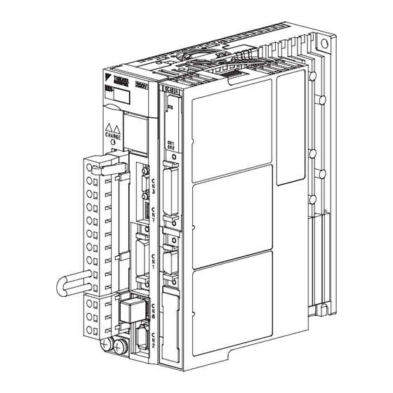
Page 26: Part Names Of The Indexer Module
2.3 Part Names of the INDEXER Module Part Names of the INDEXER Module The following figure shows the part names of the INDEXER Module. With front cover open Reserved (Do not use.) Reserved (Do not use.) LED (red) LED (green) I/O signal connector (CN11) for sequence I/O signals Serial command communications... -
Page 27: Led Indicators
2 Specifications LED Indicators The following table shows the meaning of the LED indicators. Status Red LED Green LED Control Power Supply OFF Not lit Not lit Control Power Supply ON Not lit Flashing Normal Not lit Overtravel/Software Limit Activated Resetting Saving a Table –... - Page 28 SERVOPACK Installation This chapter describes how to install the SERVOPACK. 3.1 SERVOPACK Installation Environment and Applicable Standards ..3-2 3.1.1 Installation Environment ..........3-2 3.1.2 Installation Conditions for Applicable Standards .
-
Page 29: Chapter 3 Servopack Installation
3 SERVOPACK Installation 3.1.1 Installation Environment SERVOPACK Installation Environment and Applicable Standards SERVOPACK installation environment and applicable standards are as follows. 3.1.1 Installation Environment Surrounding air temperature: 0°C to 55°C Ambient humidity: 90% RH or less (with no condensation) ... -
Page 30: Servopack Installation
3.2 SERVOPACK Installation SERVOPACK Installation 3.2.1 Orientation The SERVOPACK is available in models that are base-mounted, models that are rack-mounted, and models that are duct-ventilated. In any case, mount the SERVOPACK with a vertical orientation. Firmly secure the SERVOPACK to the mounting surface, using either two to four mounting holes depending on the SERVOPACK capacity. -
Page 31: Installation Standards
3 SERVOPACK Installation 3.2.2 Installation Standards 3.2.2 Installation Standards Observe the standards for mounting SERVOPACKs in control panels, including those for the mounting SERVOPACKs side by side in one control panel as shown in the following illustration. • SERVOPACK Mounting Orientation Mount the SERVOPACK vertically to the base, with the front panel (the side with the panel operator display) facing out. - Page 32 3.2 SERVOPACK Installation • Large-Capacity Σ-V Series 120 mm or more 100 mm or more 50 mm or more 5 mm 5 mm 120 mm or more Also install cooling fans above the SERVOPACKs and converters to disperse local pockets of warmer air around them.
-
Page 33: Emc Installation Conditions
Refer to this section for other SERVOPACK models such as the rack-mounted types as well. This section describes the EMC installation conditions satisfied in test conditions prepared by Yaskawa. The actual EMC level may differ depending on the actual system’s configuration, wiring, and other condi- tions. - Page 34 3.3 EMC Installation Conditions Three-phase 200 V • SGDV-AE1A ( = R70, R90, 1R6, 2R8, 3R8, 5R5, 7R6) + SGDV-OCA03A • SGDV-AE5A ( = R70, R90, 1R6, 2R8, 3R8, 5R5, 7R6) + SGDV-OCA03A Shield box Brake power supply One turn SERVOPACK Brake U, V, W...
- Page 35 3 SERVOPACK Installation Three-phase 200 V • SGDV-AE1A ( = 120) + SGDV-OCA03A • SGDV-AE5A ( = 120) + SGDV-OCA03A Shield box Brake power supply One turn SERVOPACK Brake U, V, W Noise Power supply: L1, L2, L3 filter Three-phase 200 VAC Servomotor One turn...
- Page 36 3.3 EMC Installation Conditions Three-phase 200 V • SGDV-AE1A ( = 180, 200, 330) + SGDV-OCA03A • SGDV-AE5A ( = 180, 200, 330) + SGDV-OCA03A Shield box Brake power supply One turn SERVOPACK Brake U, V, W Noise Power supply: L1, L2, L3 filter Three-phase 200 VAC...
- Page 37 3 SERVOPACK Installation Three-phase 200 V • SGDV-AE1A ( = 470, 550, 590, 780) + SGDV-OCA03A • SGDV-AE5A ( = 470, 550, 590, 780) + SGDV-OCA03A Shield box Brake power supply One turn SERVOPACK Brake U, V, W Noise Power supply: L1, L2, L3 filter...
- Page 38 3.3 EMC Installation Conditions Three-phase 200 V • SERVOPACK: SGDV-HE1A ( = 121, 161, 201) + SGDV-OCA03A • Converter: SGDV-COAAA ( = 2B, 3G) Shield box Power supply: Noise Three-phase L1,L2,L3 filter 200 VAC Surge Converter absorber CN101 Noise filter 200 VAC Regenerative...
- Page 39 3 SERVOPACK Installation Three-phase 400 V • SGDV-DE1A ( = 1R9, 3R5, 5R4, 8R4, 120, 170) + SGDV-OCA03A • SGDV-DE5A ( = 1R9, 3R5, 5R4, 8R4, 120, 170) + SGDV-OCA03A Shield box Noise Power supply: Brake power supply filter Single-phase 200 VAC One turn Surge...
- Page 40 3.3 EMC Installation Conditions Three-phase 400 V • SGDV-DE1A ( = 210, 260, 280, 370) + SGDV-OCA03A • SGDV-DE5A ( = 210, 260, 280, 370) + SGDV-OCA03A Shield box Noise Power supply: Brake power supply filter Single-phase 200 VAC One turn Surge SERVOPACK...
- Page 41 3 SERVOPACK Installation Three-phase 400 V • SERVOPACK: SGDV-JE1A ( = 750, 101, 131) + SGDV-OCA03A • Converter: SGDV-COADA ( = 3Z, 5E) Shield box 1T 1T Power supply: Noise L1,L2,L3 Three-phase filter 400 VAC Converter Surge Control absorber power Power supply: CN101...
- Page 42 3.3 EMC Installation Conditions Attachment Methods of Ferrite Cores One turn Two turn Cable Cable Ferrite core Ferrite core Recommended Ferrite Core • Σ-V Series Cable Name Ferrite Core Model Manufacturer Motor main circuit cable ESD-SR-250 NEC TOKIN Corp. •...
- Page 43 3 SERVOPACK Installation Fixing the Cable Fix and ground the cable shield using a piece of conductive metal. • Example of Cable Clamp Cable Shield (cable sheath stripped) Host controller side Fix and ground the cable shield using a piece of conductive metal. Ground plate Cable clamp...
- Page 44 Wiring and Connection This chapter describes examples of how a system is configured using the INDEXER Module and how the I/O signals are connected. For details on the main circuit, encoders, safety devices, and regenerative resistors, refer to the User’s Manual, Design and Maintenance for your SERVOPACK. For more information on safe and stable usage of the servo system, be sure to read the precautions in the section labeled, "...
-
Page 45: Chapter 4 Wiring And Connection
4 Wiring and Connection System Configuration Diagram The following diagram shows an example of a basic servo drive system configuration. Power supply Three-phase 200 VAC R S T Molded-case circuit breaker (MCCB) Protects the power supply line by shutting the circuit OFF when Digital operator overcurrent is detected. -
Page 46: I/O Signal Connections
Provide an external power supply; the SERVOPACK and INDEXER Module do not have an internal 24-V power supply. Yaskawa recommends using the same external power supply as that used for output cir- cuits. Confirm the characteristics of relays and other mechanical contacts before using a power supply. -
Page 47: Indexer Module I/O Signal (Cn11) Names And Functions
4 Wiring and Connection 4.2.2 INDEXER Module I/O Signal (CN11) Names and Functions (2) CN1 Output Signals Pin No. Signal Large- Name Function Name Σ-V Capacity Σ-V ALM+ Servo Alarm: Servo Alarm Output Turns OFF when an error is detected. ALM- /WARN+ Error/Warning:... - Page 48 4.2 I/O Signal Connections Signal Name Pin No. Function Power Supply for Sequence Signals. Voltage range: 24 VDC ± 10% +24V/COM This pin switches between Mode 0 and Mode 1. Mode 0 (program table operation) /MODE 0/1 OFF: Mode 1 (JOG speed table operation or homing) Mode 0: When ON, starts or restarts program table operation.
- Page 49 4 Wiring and Connection 4.2.2 INDEXER Module I/O Signal (CN11) Names and Functions (2) CN11 Output Signals Signal Name Pin No. Function /INPOSITION+ Positioning complete /INPOSITION- /POUT0+ /POUT0- /POUT1+ /POUT1- /POUT2+ /POUT2- /POUT3+ /POUT3- Programmable outputs /POUT4+ /POUT4- /POUT5+ /POUT5- /POUT6+ /POUT6- /POUT7+...
-
Page 50: Interface Circuits
4.2 I/O Signal Connections 4.2.3 Interface Circuits This section shows examples of SERVOPACK I/O signal connection to the host controller. (1) Interfaces with Sequence Input Circuits The sequence input circuit interface connects through a relay or open-collector transistor circuit. Select a low- current relay otherwise a faulty contact will result. -
Page 51: Example Of I/O Signal Connections
4 Wiring and Connection 4.2.4 Example of I/O Signal Connections 4.2.4 Example of I/O Signal Connections The following diagram shows a typical connection example. (1) SERVOPACK Σ-V Series Photocoupler output Max. operating voltage: 30 VDC Max. operating current: 50 mA DC SGDV SERVOPACK Control power supply 3.3 kΩ... - Page 52 4.2 I/O Signal Connections Large-Capacity Σ-V Series Photocoupler output Max. operating voltage: 30 VDC Max. operating current: 50 mA DC SGDV SERVOPACK Control power supply 3.3 kΩ +24 VIN +24 V for sequence signal ALM+ Servo alarm output ALM- (OFF for an alarm) /SI1 /ALM-RST...
- Page 53 4 Wiring and Connection 4.2.4 Example of I/O Signal Connections (2) INDEXER Module SGDV SERVOPACK CN10 CN11 (Sinking or sourcing) CN11 3.3 kΩ ON: Mode 0 /INPOSITION+ OFF: Mode 1 /MODE 0/1 /INPOSITION- /POUT0+ /START-STOP ; /HOME /POUT0- /POUT1+ /PGMRES ; /JOGP /POUT1- /POUT2+ /SEL0 ;...
-
Page 54: Serial Command Communications Connector (Cn12)
4.3 Serial Command Communications Connector (CN12) Serial Command Communications Connector (CN12) Serial commands can be used to perform operations such as positioning, setting parameters and program tables, monitoring, and other operations. RS-422 or RS-485 Host controller 4.3.1 Communications Specifications The following table shows the communications specifications of the CN12 connector. Item Specifications Full duplex (RS-422) or half duplex (RS-485) -
Page 55: Connector Model
4 Wiring and Connection 4.3.2 Connector Model 4.3.2 Connector Model INDEXER Applicable Receptacles Module-end Solder Type Case Manufacturer Connector 10214-52A2PL 10114-3000PE 10314-52A0-008 3M Japan Limited 4.3.3 Connector Signal Names Pin No. Signal Name Signal Circuit Name Signal Direction Host controller ← INDEXER Module Transmit data (not inverted) Host controller ←... -
Page 56: Connection Examples
4.3 Serial Command Communications Connector (CN12) 4.3.4 Connection Examples (1) Full-duplex Wiring RS-422 or RS-485 port INDEXER Module Signal Signal Pin No. Name Name /RXD /TXD /TXD /RXD /RXD /TXD Case FG To next axis Pin No. 5 FG Full-duplex Wiring ∗... -
Page 57: Rs-422/Rs-485 Interface
4 Wiring and Connection 4.3.5 RS-422/RS-485 Interface 4.3.5 RS-422/RS-485 Interface The maximum total length for RS-422 or RS-485 cable is 50 m. Use the minimum length of cable that is needed. The INDEXER Module’s communications circuits are not insulated. If communications errors occur because of noise, use noise suppression methods such as shielded cable or ferrite cores. -
Page 58: Power Loss In The Indexer Module
4.4 Power Loss in the INDEXER Module Power Loss in the INDEXER Module Power loss in the INDEXER Module is shown below. The INDEXER Module’s power is supplied from the SERVOPACK. INDEXER Module Specifications Item Specifications Min. operating voltage 5.05 V Max. - Page 59 Parameter Setting and Functions This chapter describes the use of the I/O signals in the SERVOPACK and INDEXER Module (I/O signals in the CN1 and CN11 connectors) as well as the procedure for setting the related parameters for the intended purposes. The following sections can be used as references for this chapter.
-
Page 60: Parameter Configurations
5 Parameter Setting and Functions Parameter Configurations Parameters are comprised of the types shown in the following table. Refer to Chapter 10. Type Parameter No. Description Select basic and application functions such as the Function Selection Pn000 to Pn010 type of control mode or the stop method when an Parameters PnB1F alarm occurs. -
Page 61: Restrictions On Servopack Parameters
5.2 Restrictions on SERVOPACK Parameters Restrictions on SERVOPACK Parameters The following parameters are set automatically when an INDEXER Module is installed on a SERVOPACK. Do not change these parameters because they are reserved for system use. Also, the SERVOPACK will be set for position control. - Page 62 5 Parameter Setting and Functions (cont’d) Parameter Digit Description Setting Description Output Signal Inversion Σ-V Series: The INDEXER Module sets a value matched to CN1-1 or -2 terminals 0 or 1 PnB1C and PnB51. Large-Capacity Σ-V Series: CN1-25 or -26 terminals Output Signal Inversion Σ-V Series: The INDEXER Module sets a value matched to...
-
Page 63: Sequence I/O Signals
5.3 Sequence I/O Signals Sequence I/O Signals This section explains sequence I/O signals. In this section, the word “open” or “close” shown in parentheses in parameter descriptions indicates that the contact is open or closed. 5.3.1 Servo ON Signal (/S-ON) This sets the servo ON signal (/S-ON) that determines whether the servomotor power is ON or OFF. - Page 64 5 Parameter Setting and Functions 5.3.2 Overtravel (2) Changing Input Signal Settings The settings of the input signals for overtravel can be changed with the parameters below. Parameter Meaning When Enabled When input signal is OFF (open), forward run is prohibited (forward [Factory setting] overtravel).
-
Page 65: Servo Alarm Output Signal (Alm) And Alarm Code Output Signals (/Alo1, /Alo2, And /Alo3)
5.3 Sequence I/O Signals 5.3.3 Servo Alarm Output Signal (ALM) and Alarm Code Output Signals (/ALO1, /ALO2, and /ALO3) This section describes signals that are output when the SERVOPACK detects errors and resetting methods. (1) Servo Alarm Output Signal (ALM) This signal is output when the SERVOPACK detects an error. - Page 66 5 Parameter Setting and Functions 5.3.3 Servo Alarm Output Signal (ALM) and Alarm Code Output Signals (/ALO1, /ALO2, and /ALO3) (3) Alarm Reset Method If a servo alarm (ALM) occurs, first eliminate the cause of that alarm, then reset the alarm. It is sometimes not possible to reset encoder-related alarms with the /ALM-RST signal.
-
Page 67: Braking Signal (/Bk)
5.3 Sequence I/O Signals 5.3.4 Braking Signal (/BK) • Inverting the polarity of the brake output signal (/BK), i.e. positive logic, will prevent the holding brake from working in case of its signal line disconnection. If this setting is absolutely necessary, check the operation and confirm that there are no safety problems. -
Page 68: Servo Ready Output Signal (/S-Rdy)
5 Parameter Setting and Functions 5.3.5 Servo Ready Output Signal (/S-RDY) 5.3.5 Servo Ready Output Signal (/S-RDY) This signal is turned ON when the SERVOPACK is ready to accept the servo ON (/S-ON) signal. The /S-RDY signal is turned ON under the following conditions. •... -
Page 69: Positioning Completed Output Signal (/Inposition)
5.3 Sequence I/O Signals 5.3.7 Positioning Completed Output Signal (/INPOSITION) This signal indicates that servomotor positioning has been completed. The signal is output when the motor stops, even if the current position has not reached the target position. If the difference between the reference from the INDEXER Module and the movement of the servomotor (the number of position error pulses) drops below the value set for this parameter, the positioning completed signal will be output. -
Page 70: Programmable Output Signals (/Pout0 To /Pout7)
5 Parameter Setting and Functions 5.3.8 Programmable Output Signals (/POUT0 to /POUT7) 5.3.8 Programmable Output Signals (/POUT0 to /POUT7) The basic use and wiring procedure for the programmable outputs (/POUT0 to /POUT7) are given below. The programmable output signals can be changed by the user through the program table’s POUT bits or the POUT serial command. -
Page 71: Settings According To Device Characteristics
5.4 Settings According to Device Characteristics Settings According to Device Characteristics This section describes the procedure for setting parameters according to the dimensions and performance of the equipment used. 5.4.1 Setting Reference Units Reference units are the position and distance units that are used between the host controller and INDEXER Module. - Page 72 5 Parameter Setting and Functions 5.4.1 Setting Reference Units (3) Setting Speeds in Reference Units Calculate the positioning speed. <Example> Reference unit: 0.01 mm Desired positioning speed: 15 m/min 15000 mm/min = 1500000 reference units/min 0.01 mm Thus, the positioning speed setting is 1500 [1000 reference units/min]. Specify the positioning speed and registration speed in the program table in SPD and RSPD.
- Page 73 5.4 Settings According to Device Characteristics Using the parameters below, set the acceleration and deceleration, and set the average movement time of posi- tion references. Acceleration rate Setting Range Setting Unit Factory Setting When Enabled PnB29 1000 1 to 99999999 (Reference units/min)/ 1000 Immediately...
-
Page 74: Moving Mode And Coordinate Settings
5 Parameter Setting and Functions 5.4.2 Moving Mode and Coordinate Settings 5.4.2 Moving Mode and Coordinate Settings Use the following parameters to set the moving mode and coordinates. Parameter Meaning When Enabled Sets coordinates to linear type. [Factory setting] Sets coordinates to rotary type. Moving mode is set as shortest path. PnB20 After restart Sets coordinates to rotary type. - Page 75 5.4 Settings According to Device Characteristics (2) When the Coordinates are the Rotary Type When using a rotary type coordinates such as with a rotary table, set PnB20 to 1 (shortest path), to 2 (forward), or to 3 (reverse). Then set the end point of rotational coordinates in PnB21 and the starting point of rotational coordinates in PnB23.
-
Page 76: Setting Home Position
5 Parameter Setting and Functions 5.4.3 Setting Home Position 5.4.3 Setting Home Position Set the origin or the difference between the reference coordinates and absolute encoder position (the absolute encoder offset) for parameter PnB25. Origin (Incremental Encoder) Absolute Encoder Offset (Absolute Encoder) PnB25 Setting Range Setting Unit... -
Page 77: Backlash Compensation
5.4 Settings According to Device Characteristics 5.4.4 Backlash Compensation This parameter can be set to compensate for positioning offset caused by the backlash of gears. Backlash Compensation PnB50 Setting Range Setting Unit Factory Setting When Enabled -1000 to 1000 Reference unit Immediately Specify the direction for compensation with the sign and the quantity of the compensation with a numeric value. -
Page 78: Fully-Closed Loop Control
5 Parameter Setting and Functions 5.4.6 Fully-closed Loop Control 5.4.6 Fully-closed Loop Control For more information on the settings for fully-closed loop control, refer to the User’s Manual, Design and Maintenance for your SERVOPACK. When using the fully-closed loop control with an INDEXER Module, some restrictions apply to the setting for parameter Pn20A (External Encoder Pitches.) Set parameter Pn20A (External Encoder Pitches) to a value within the recommended range. -
Page 79: Program Table
Program Table The chapter describes how to set and operate a program table. 6.1 Program Table ..........6-2 6.1.1 Mode Switch Signal (/MODE 0/1) . -
Page 80: Mode Switch Signal (/Mode 0/1)
6 Program Table 6.1.1 Mode Switch Signal (/MODE 0/1) Program Table This section explains program table. In this section, the word “open” or “close” shown in parentheses in parameter descriptions indicates that the contact is open or closed. 6.1.1 Mode Switch Signal (/MODE 0/1) If the /MODE 0/1 input signal is active, the mode is set to program table operation mode (Mode 0). - Page 81 6.1 Program Table (2) Related Parameters Make the settings for program table operation with the parameters below. Parameter Meaning When Enabled Starts program table operation when /START-STOP signal is ON (close). [Factory setting] Stops program table operation when /START-STOP signal is OFF (open).
-
Page 82: Program Table Step Selection
6 Program Table 6.1.3 Program Table Step Selection 6.1.3 Program Table Step Selection Use the 8-bit selection signals (/SEL0 to /SEL7) to specify PGMSTEP 0 to 255. Selection Signal Status PGMSTEP /SEL7 /SEL6 /SEL5 /SEL4 /SEL3 /SEL2 /SEL1 /SEL0 Active Active Active Active... -
Page 83: Program Table Settings
6.1 Program Table 6.1.4 Program Table Settings This section explains the program table settings. If the edited program table is saved to flash memory, it will be saved even after the control power supply is turned OFF. Use one of the following methods to save the program table to flash memory. •... - Page 84 6 Program Table 6.1.4 Program Table Settings (cont’d) Item Function Description 1 to 99999999: Registration speed [1000 reference units/min] RSPD Registration speed The factory setting is 1000. 1 to 99999999: Acceleration [1000 (reference units/min)/ms] “:”: Continues with acceleration specified in the most previously executed program step.
- Page 85 6.1 Program Table (cont’d) Item Function Description Set the condition to use to determine when the program step has been completed. For example, with the factory setting of IT0, the pass condition is met 0 ms after /INPOSITION becomes active. When the pass condition is met, the PGMSTEP that was specified for NEXT will be executed if the number of execution times specified for LOOP has been reached.
-
Page 86: Examples Of Event Conditions
6 Program Table 6.1.5 Examples of EVENT Conditions 6.1.5 Examples of EVENT Conditions The following figures show examples of EVENT conditions. IT2000 Reference speed Motor speed Speed Speed NT2000 t = 2000 ms Reference speed Motor speed Speed Speed t = 2000 ms DT2000 Speed Speed... -
Page 87: Program Table Operation
6.1 Program Table 6.1.6 Program Table Operation (1) Starting and Stopping the Program If the /START-STOP signal becomes active when program table operation has been canceled, /SEL0 to /SEL7 will be latched and the program will be executed from the PGMSTEP specified with /SEL0 to /SEL7. Speed Canceled Operating... -
Page 88: Status Changes In Program Table Operation
6 Program Table 6.1.7 Status Changes in Program Table Operation (2) Resetting the Program The program will be canceled if the /PGMRES signal becomes active while the program is stopped (when the /PGMRES signal is on the rising edge and the /START-STOP signal is inactive.) /START-STOP Canceled Operating Stopped... -
Page 89: Input Signal Timing Specifications For Program Table Operation
6.1 Program Table 6.1.8 Input Signal Timing Specifications for Program Table Operation The following figures show the timing specifications of program table input signals. /MODE 0/1 /START-STOP 0 ms min. 4 ms min. /PGMRES /START-STOP 4 ms min. 4 ms min. /START-STOP /SEL0 to /SEL7 2 ms min. -
Page 90: Response Times After Turning On The /Start-Stop Signal
6 Program Table 6.1.9 Response Times after Turning ON the /START-STOP Signal 6.1.9 Response Times after Turning ON the /START-STOP Signal The response times after turning ON the /START-STOP signal are shown below. /START-STOP Motor movement /INPOSITION /POUT0 to 7 Time Normal Under Special Conditions*... -
Page 91: Program Table Examples
6.1 Program Table 6.1.10 Program Table Examples This section provides examples of program tables. (1) Simple Round-trip Operation PGMSTEP RDST RSPD POUT EVENT LOOP NEXT I+200000 15000 – 1000 NNNNNNNA IT2000 I−200000 30000 – 1000 NNNNNNAN IT2000 PGMSTEP 0 PGMSTEP 1 PGMSTEP 1 PGMSTEP 0 LOOP = 1... - Page 92 6 Program Table 6.1.10 Program Table Examples (3) Using /SELx Signal with EVENT Function PGMSTEP RDST RSPD POUT EVENT LOOP NEXT I+200000 15000 – 1000 NNNNNNNA SEL0T2000 I−200000 30000 – 1000 NNNNNNAN SEL1T2000 PGMSTEP 0 PGMSTEP 1 PGMSTEP 1 PGMSTEP 0 LOOP = 1 LOOP = 1 LOOP = 2...
- Page 93 6.1 Program Table (4) Using ZONE Table PGMSTEP RDST RSPD POUT EVENT LOOP NEXT A+500000 30000 – 1000 NNNZZZZZ A+000000 30000 – 1000 NNNZZZZZ PGMSTEP 0 PGMSTEP 1 PGMSTEP 0 PGMSTEP 1 PGMSTEP 0 Speed /START-STOP /INPOSITION /POUT0 /POUT1 /POUT2 /POUT3 /POUT4 ...
- Page 94 6 Program Table 6.1.10 Program Table Examples (5) Using as Positioning Table PGMSTEP RDST RSPD POUT EVENT LOOP NEXT A+000000 30000 – 1000 NNNAZZZZ A+100000 30000 – 1000 NNNNZZZZ A+200000 30000 – 1000 NNNAZZZZ A+300000 30000 – 1000 NNNNZZZZ A+400000 30000 –...
- Page 95 6.1 Program Table (6) Using INFINITE PGMSTEP RDST RSPD POUT EVENT LOOP NEXT +INFINITE 15000 – 1000 NNNNNNNN T2000 +INFINITE 30000 – 1000 : : : : : : : : SEL0TO STOP 30000 – 1000 : : : : : : : : A+400000 30000 –...
- Page 96 6 Program Table 6.1.10 Program Table Examples (8) Using Continuous Stop Function PGMSTEP RDST RSPD POUT EVENT LOOP NEXT +INFINITE 1080000 – – 1080 NNNNNNNA T2000 1080 S+45000 – – 1080 NNNNNNAN SEL5T0 1000 1080 ∗1. When using the continuous stop function, the Deceleration (DEC) specified in the preceding program step is dis- abled.
-
Page 97: Registration
6.2 Registration Registration Positioning is performed for the specified distance and specified speed from the position where the /RGRT signal is latched. Speed Registration speed Registration distance /RGRT 6.2.1 Registration Timing Specifications The following figure shows the latch timing specifications. /RGRT Latch operation •... -
Page 98: Registration Input Setting
6 Program Table 6.2.2 Registration Input Setting 6.2.2 Registration Input Setting Parameter PnB12 sets the logic for the /RGRT Registration Latch Signal. (1) Signal Specifications Pin No. Large- Type Signal Name Setting Meaning Σ-V Capacity Σ-V The current position has reached the latch posi- ON (close) tion. - Page 99 6.2 Registration The second and later latch signals are ignored. Speed /START-STOP /RGRT The /RGRT latch signal can also be input while the program is stopped. Speed Registration target position /START -STOP /RGRT Even if the program is stopped during registration operation, the registration operation will be restarted if the program is restarted.
-
Page 100: Zone Table Settings
6 Program Table ZONE Table Settings ZONE signals indicate regions defined in the ZONE table. ZONE signals are allocated to the regions using the ZONE table. Outputs /POUT0 to /POUT4 must be specified as ZONE signals in order to use ZONE signals. If the edited ZONE table is saved to flash memory, it will be saved even after the control power supply is turned OFF. - Page 101 6.3 ZONE Table Settings Note 1. The “---” symbols indicate an inactive signal status. 2. ZONE ID: ZONE Number ZONE N: Negative side ZONE boundary position ZONE P: Positive side ZONE boundary position Z0 to Z4: If the programmable output signals (/POUT0 to /POUT4) are specified as ZONE signals, /POUT0 = Z0, /POUT1 = Z1, /POUT2 = Z2, /POUT3 = Z3, and /POUT4 = Z4.
-
Page 102: Homing/Jog Speed Table
6 Program Table 6.4.1 Mode Switch Input Signal (/MODE 0/1) Homing/JOG Speed Table 6.4.1 Mode Switch Input Signal (/MODE 0/1) If the /MODE 0/1 input signal is inactive, the mode is set to Mode 1 (homing/JOG speed table operation mode). (1) Signal Specifications Type Signal Name... - Page 103 6.4 Homing/JOG Speed Table (2) Related Parameters The homing/JOG speed table operation signal can be set with the following parameters. Parameter Meaning When Enabled Starts homing when input signal is ON (close). [Factory setting] PnB04 Starts homing when input signal is OFF (open). 2, 3 Does not start homing.
-
Page 104: Parameters Related To Homing
6 Program Table 6.4.3 Parameters Related to Homing 6.4.3 Parameters Related to Homing Set the homing parameters with the parameters listed in the following table. Origin (Incremental Encoder) Absolute Encoder Offset (Absolute Encoder) PnB25 Setting Range Setting Unit Factory Setting When Enabled -99999999 to 99999999 Reference unit... -
Page 105: Homing
6.5 Homing Homing Homing starts when the /HOME signal becomes active. Homing stops if the /HOME signal becomes inactive again. If the /HOME signal becomes active again while the homing is stopped, homing will be restarted from the point where it was interrupted. The homing will be canceled if operation is switched to JOG speed table mode with the /JOGP signal or / JOGN signal, or the mode is switched with the /MODE 0/1 signal while the homing is stopped. -
Page 106: Jog Speed Table Operation
6 Program Table 6.6.1 Example of JOG Speed Table Operation JOG Speed Table Operation The /JOGP signal executes forward operation and the /JOGN signal executes reverse operation. The /JOG0 to /JOG3 signals select the speed. 6.6.1 Example of JOG Speed Table Operation The following diagram shows an example of JOG Speed Table operation. -
Page 107: Jog Speed Table
6.6 JOG Speed Table Operation 6.6.2 JOG Speed Table A total of 16 speeds can be set for JSPD0 to JSPD15. If the edited JOG speed table is saved to flash memory, it will be saved even after the control power supply is turned OFF. -
Page 108: Input Conditions For Homing And Jog Speed Table Operation
6 Program Table 6.6.3 Input Conditions for Homing and JOG Speed Table Operation 6.6.3 Input Conditions for Homing and JOG Speed Table Operation The following table shows the functions of the signals related to homing and JOG speed table operation. /HOME /JOGP /JOGN... - Page 109 Serial Command Communications This chapter describes the INDEXER Module’s serial command communications. 7.1 CN12 Connector Specifications ....... . . 7-2 7.2 Settings .
-
Page 110: Chapter 7 Serial Command Communications
7 Serial Command Communications CN12 Connector Specifications The following table shows the specifications of the CN12 connector. Item Specifications Full duplex (RS-422 or RS-485) or half duplex (RS-485) Interface (Set the appropriate wiring method with parameter PnB00.) Synchronization Start-stop synchronization (ASYNC) 9600, 19200, or 38400 bps Bit Rate (Selectable with parameter PnB01.) -
Page 111: Settings
7.2 Settings Settings This section explains the settings for the INDEXER Module’s serial commands. 7.2.1 Block Diagram The following block diagram shows the basic connections for multi-axis control. Host controller SGDV SGDV CN12 CN12 Up to 16 axes can be connected. For details on wiring, refer to 4.3 Serial Command Communications Connector (CN12). -
Page 112: Command/Response Format
7 Serial Command Communications Command/Response Format The following diagram shows the command/response format. Command (Host controller → INDEXER Module) Response (Host controller ← INDEXER Module) Axis no. Response character string Delimiter Axis no. Command character string Delimiter Example: 1SVON [CR] Example: 1OK [CR] [LF] 2SVON [CR]... -
Page 113: Global Commands
7.4 Global Commands Global Commands Global commands are commands that are sent to all axes at the same time. Command (Host controller → INDEXER Module) Response (Host controller ← INDEXER Module) “*” Command character string Delimiter Example: *SVON [CR] *ST [CR] No response returned. -
Page 114: Echoback Response Time
7 Serial Command Communications Echoback Response Time The following diagram shows the response time from the command transmission until the echoback. Stop bit Command High impedance High impedance Echoback Start bit Min. Max. PnB00 (Protocol) Settings 1: Full-duplex wiring is used for communications Bit rate ×... -
Page 115: Response Data Details
7.6 Response Data Details Response Data Details There are positive responses and negative responses. The positive response indicates normal operation and the negative response indicates an error. 7.6.1 Positive Responses There two kinds of positive responses, responses that return data (for commands such as PRM) and responses that do not return data (for commands such as SVON). -
Page 116: Serial Commands
7 Serial Command Communications 7.7.1 Basic Operation Commands Serial Commands The axis number and delimiter are attached to actual serial commands, but are omitted here. Some data in responses (such as parameters, table numbers, and monitored data) is expressed numerically. The presence/absence of the sign and the number of digits are correct in the numerical data shown in these exam- ples, but the sign and numerical value will vary in actual applications. -
Page 117: Control Commands
7.7 Serial Commands 7.7.2 Control Commands The following table shows the control commands. Control Commands Positive Serial Command Function/Description Response Target Position Specification (Absolute Position) Setting range: −99999999 ≤ nnnnnnnn ≤ +99999999 [Reference units] Specifies the target position as an absolute position. Speed SPDx POSy or... - Page 118 7 Serial Command Communications 7.7.2 Control Commands Control Commands (cont’d) Positive Serial Command Function/Description Response Acceleration Specification Setting range: 1 ≤ nnnnnnnn ≤ +99999999 [1000 (reference units/min)/ms] Speed reference ACCnnnnnnnn Time V [× 1000 reference units/min] Acceleration = [ms] V [× 1000 reference units/min] Deceleration = [ms] Note: The acceleration setting in parameter PnB29 can also be used.
- Page 119 7.7 Serial Commands Control Commands (cont’d) Positive Serial Command Function/Description Response Positioning Start (Absolute Position) Setting range: −99999999 ≤ nnnnnnnn ≤ +99999999 [Reference units] Specifies the absolute position nnnnnnnn as the target position and starts positioning at the same time. This command is equivalent to the following combination: POSA + nnnnnnnn →...
- Page 120 7 Serial Command Communications 7.7.2 Control Commands Control Commands (cont’d) Positive Serial Command Function/Description Response Registration Distance Specification Setting range: 0 ≤ nnnnnnnn ≤ 99999999 [Reference units] Specifies the registration distance that is used in the RS, RSnnnnnnnn, RSAnnnnnnnn, and RSInnnnnnnn commands.
- Page 121 7.7 Serial Commands Control Commands (cont’d) Positive Serial Command Function/Description Response Positioning Start with Registration Starts positioning with the speed specified by the SPD command and the target position speci- fied by the POS, POSA, or POSI command. If the /RGRT signal goes ON during positioning, that position is latched and the motor will move the specified relative distance from the latched position.
- Page 122 7 Serial Command Communications 7.7.2 Control Commands Control Commands (cont’d) Positive Serial Command Function/Description Response Positioning Start with Registration (Relative Distance) Setting range: −99999999 ≤ nnnnnnnn ≤ +99999999 [Reference units] Specifies the relative distance nnnnnnnn as the target position and starts registration positioning RSI (±) nnnnnnnn at the same time.
- Page 123 7.7 Serial Commands Control Commands (cont’d) Positive Serial Command Function/Description Response JOG Forward/Reverse with Registration Setting range: 1 ≤ nnnnnnnn ≤ 99999999 [1000 reference units/min] Starts JOG forward or JOG reverse operation at the speed specified in nnnnnnnn. RJOGPnnnnnnnn: Forward RJOGNnnnnnnnn: Reverse If the /RGRT signal goes ON during forward/reverse jogging, that position is latched and the motor will move the specified relative distance from the latched position.
- Page 124 7 Serial Command Communications 7.7.2 Control Commands Control Commands (cont’d) Positive Serial Command Function/Description Response Homing Start Starts homing. When homing has been stopped with the HOLD command, homing will be restarted (the hold will be cleared) when the ZRN command is executed again. The parameters for homing are specified in parameters PnB31 to PnB39.
- Page 125 7.7 Serial Commands Control Commands (cont’d) Positive Serial Command Function/Description Response Origin (Incremental Encoder) Absolute Encoder Offset (Absolute Encoder) PnB25 Setting Range Setting Unit Factory Setting When Enabled -99999999 to Reference unit After restart +99999999 Parameter Meaning When Enabled [Factory Does not execute homing.
- Page 126 7 Serial Command Communications 7.7.2 Control Commands Control Commands (cont’d) Positive Serial Command Function/Description Response Coordinates Setting Note: It can be dangerous to execute this command carelessly to switch the coordinates of the reference position. After executing this command, confirm that the reference position and the new coordinates are in agreement before starting operation.
- Page 127 7.7 Serial Commands Control Commands (cont’d) Positive Serial Command Function/Description Response Positioning Interruption Interrupts the current positioning. The remainder of the positioning is put on hold. When the HOLD command has interrupted a positioning initiated by an ST, STnnnnnnnn, STAnnnnnnnn, or STInnnnnnnn command, the positioning can be restarted by executing the ST command.
- Page 128 7 Serial Command Communications 7.7.2 Control Commands Control Commands (cont’d) Positive Serial Command Function/Description Response Even if a new target position is specified before the HOLD command is executed, the remaining distance will be canceled and the new target position will be used instead. Speed POSIz SPDx...
- Page 129 7.7 Serial Commands Control Commands (cont’d) Positive Serial Command Function/Description Response POUT Specification Specifies the operation of programmable output signals /POUT0 to /POUT7. Settings: N: Inactive A: Active Z: Zone table “:”: Continue POUTnnnnnnnn POUT n n n n n n n n /POUT0 /POUT1 /POUT2...
-
Page 130: Parameter Edit Commands
7 Serial Command Communications 7.7.3 Parameter Edit Commands 7.7.3 Parameter Edit Commands The following table shows the Parameter Edit Commands. Parameter Edit Commands Serial Command Function/Description Positive Response Parameter Read An 8-digit signed decimal value is returned for commands PRM124, PRM164, PRM165, PRM550 to PRM553, PRMB21, PRMB23, PRMB25, Reads a parameter. - Page 131 7.7 Serial Commands Parameter Edit Commands (cont’d) Serial Command Function/Description Positive Response Parameter Initialization PRMINIT Resets all parameters to their factory settings. After executing PRMINIT, turn the control power supply OFF and ON. 7-23...
-
Page 132: Program Table Setup Commands
7 Serial Command Communications 7.7.4 Program Table Setup Commands 7.7.4 Program Table Setup Commands The following table shows the Program Table Setup Commands. Program Table Setup Commands Serial Command Function/Description Positive Response Program Table Save Saves the program table in flash memory. Once PGMSTORE is executed, the program table will be retained after the control power supply is turned OFF. - Page 133 7.7 Serial Commands Program Table Setup Commands (cont’d) Serial Command Function/Description Positive Response Program Table RDST Read RDSTT123 = 12345678 [CR] [LF] RDSTTsss RDSTT123 = -[SP] [SP] [SP] [SP] [SP] Reads the RDST value (registration distance). [SP] [SP] [CR] [LF] sss: Program step (PGMSTEP) Program Table RDST Write Sets the RDST value (registration distance).
- Page 134 7 Serial Command Communications 7.7.4 Program Table Setup Commands Program Table Setup Commands (cont’d) Serial Command Function/Description Positive Response Program Table POUT Write Sets the POUT value (programmable output signal). sss: Program step (PGMSTEP) Settings: N: Inactive A: Active Z: Zone table “:”: Continues the previously executed program step’s specifi- POUTTsss = nnnnnnnn cation.
- Page 135 7.7 Serial Commands Program Table Setup Commands (cont’d) Serial Command Function/Description Positive Response Program Table LOOP Write Sets the LOOP value (number of repetitions). LOOPTsss = nnnnn sss: Program step (PGMSTEP) Setting: 1 ≤ nnnnn ≤ 99999 Program Table NEXT Read NEXTT123 = 12345 [CR] [LF] NEXTTsss Reads the NEXT value (link destination).
-
Page 136: Program Table Operation Commands
7 Serial Command Communications 7.7.5 Program Table Operation Commands 7.7.5 Program Table Operation Commands The following table shows the Program Table Operation Commands. Program Table Operation Commands Serial Command Function/Description Positive Response Program Table Operation Start Starts program table operation from program step sss. sss: Program step (PGMSTEP) STARTsss When program table operation has been interrupted by the... -
Page 137: Zone Table Setup Commands
7.7 Serial Commands 7.7.6 Zone Table Setup Commands The following table shows the Zone Table Setup Commands. Zone Table Setup Commands Serial Command Function/Description Positive Response Zone Table Save Saves the zone table in flash memory. ZONESTORE Once ZONESTORE is executed, the zone table will be retained after the control power supply is turned OFF. -
Page 138: Jog Speed Table Setup Commands
7 Serial Command Communications 7.7.7 JOG Speed Table Setup Commands 7.7.7 JOG Speed Table Setup Commands The following table shows the JOG Speed Table Setup Commands. JOG Speed Table Setup Commands Serial Command Function/Description Positive Response JOG Speed Table Save Saves the JOG speed table in flash memory. -
Page 139: Monitor And Utility Function Commands
7.7 Serial Commands 7.7.8 Monitor and Utility Function Commands The following table shows the Monitor and Utility Function Commands. Monitor and Utility Function Commands Serial Command Function/Description Positive Response One of the following responses is returned depend- ing on the status. •... - Page 140 7 Serial Command Communications 7.7.8 Monitor and Utility Function Commands Monitor and Utility Function Commands (cont’d) Serial Command Function/Description Positive Response IN2 = 10101010101 [CR] [LF] 0: Photocoupler OFF 1: Photocoupler ON Bit 0: /MODE 0/1 Bit 1: /START-STOP; /HOME Bit 2: /PGMRES;...
- Page 141 7.7 Serial Commands Monitor and Utility Function Commands (cont’d) Serial Command Function/Description Positive Response OUT1 = 01010101 [CR] [LF] 0: Photocoupler OFF 1: Photocoupler ON Bit 0: ALM OUT1 SERVOPACK Output Signal Monitor Bit 1: /WRN Bit 2: /BK Bit 3: /S-RDY Bit 4: ALO1 Bit 5: ALO2 Bit 6: ALO3...
- Page 142 7 Serial Command Communications 7.7.8 Monitor and Utility Function Commands Monitor and Utility Function Commands (cont’d) Serial Command Function/Description Positive Response Program Table Operation LOOP Pass Through LOOP LOOP = 12345 [CR] [LF] Monitor Monitor Read (1 ≤ n ≤ 11) See following description of the responses for STS MONn to RDST.
- Page 143 7.7 Serial Commands Monitor and Utility Function Commands (cont’d) Serial Command Function/Description Positive Response Motor Model Code Display 0 1 1 1 Voltage Motor model 00 = 100 VAC 11 = SGMMJ 01 = 200 VAC 32 to 39 = SGMCS 02 = 400 VAC 40 = linear motor MTTYPE = 00001234 [CR] [LF]...
- Page 144 Operation of Digital Operator This chapter describes how to operate the digital operator when an INDEXER Module is installed. For details on the basic operation of the digital operator, refer to the following manuals. Σ Σ • -V Series or Large-Capacity -V Series User’s Manual Design and Maintenance Command Option Attachable Type Σ...
-
Page 145: Chapter 8 Operation Of Digital Operator
8 Operation of Digital Operator 8.1.1 Functions List Overview 8.1.1 Functions List The table below shows whether functions of the digital operator can or cannot be used when an INDEXER Module is installed. This chapter describes the operating procedures for the functions indicated with the thick-bordered frame in Σ... -
Page 146: Reading The Screen
8.1 Overview 8.1.3 Reading the Screen • The SERVOPACK status is always displayed at the top left of the screen ( Base blocked RUN: Servomotor is ON A. : Alarm/warning is in effect ( is the alarm/warning code). PT NT: Forward run and reverse run prohibited (Over travel) P-OT: Forward run prohibited (Over travel) -
Page 147: Operation Of Utility Functions
8 Operation of Digital Operator 8.2.1 Utility Functions Operation of Utility Functions 8.2.1 Utility Functions The following table shows whether utility functions can be set or not with the digital operator. Possible/ Fn No. Function Remarks and Reference Possible This utility function cannot be used. Exe- Fn000 ×... - Page 148 8.2 Operation of Utility Functions (cont’d) Possible/ Fn No. Function Remarks and Reference Possible FnB04 ZONE table edit/save 8.2.3 FnB05 JOG speed table edit/save 8.2.4 FnB06 Program table initialization 8.2.5 FnB07 ZONE table initialization 8.2.6 FnB08 JOG speed table initialization ...
-
Page 149: Program Table Edit/Save (Fnb03)
8 Operation of Digital Operator 8.2.2 Program Table Edit/Save (FnB03) 8.2.2 Program Table Edit/Save (FnB03) This function edits and saves program tables. Saving a program table to flash memory after editing it ensures that the data will be retained even after the control power has been turned off. ... - Page 150 8.2 Operation of Utility Functions (cont’d) Step Display after Operation Keys Operation On pressing the key, the setting is entered and the cursor returns to the program table article and program step side. Repeat steps 3 to 6 to set the program table. On completing the setting of all the program tables to be used, save the program tables to flash memory by following the procedure in (4) Saving Program Tables.
- Page 151 8 Operation of Digital Operator 8.2.2 Program Table Edit/Save (FnB03) (3) Details on How to Set Table Settings Details on the setting method for step 5 in 8.2.2 (2) Editing Program Table are shown below. POS: Target Position Change positioning Change target position Move cursor type...
- Page 152 8.2 Operation of Utility Functions ACC: Acceleration Move cursor Change acceleration If the value becomes less than 1, “:” is displayed. Note: For details on the acceleration, refer to 6.1.4 (1) Program Table Functions. DEC: Deceleration Move cursor Change deceleration If the value becomes less than 1, “:”...
- Page 153 8 Operation of Digital Operator 8.2.2 Program Table Edit/Save (FnB03) LOOP: Number of Executions Move cursor Change number of executions Note: For details on the number of executions, refer to 6.1.4 (1) Program Table Functions. NEXT: PGMSTEP to be Executed Next Move cursor Change next PGMSTEP to be executed If the value becomes less than 0,...
-
Page 154: Zone Table Edit/Save (Fnb04)
8.2 Operation of Utility Functions 8.2.3 ZONE Table Edit/Save (FnB04) This function edits and saves ZONE tables. Saving a ZONE table to flash memory after editing it ensures that the data will be retained even after the control power has been turned off. ... - Page 155 8 Operation of Digital Operator 8.2.3 ZONE Table Edit/Save (FnB04) Method for Moving the Cursor The values within the frames in the figure below are the ZONE table numbers displayed at the digital operator. ZONEP ZONEP Moves the displayed column one column at a time to the left or right.
- Page 156 8.2 Operation of Utility Functions (cont’d) Step Display after Operation Keys Operation When saving to flash memory has been completed nor- – mally, the display returns to the ZONE table editing screen. Press the key to return to the Utility Function Mode main menu.
-
Page 157: Jog Speed Table Edit/Save (Fnb05)
8 Operation of Digital Operator 8.2.4 JOG Speed Table Edit/Save (FnB05) 8.2.4 JOG Speed Table Edit/Save (FnB05) This function edits and saves JOG speed tables. Saving a JOG speed table to flash memory after editing it ensures that the data will be retained even after the control power has been turned off. For details on how to read the screen, refer to 8.1.3 Reading the Screen. - Page 158 8.2 Operation of Utility Functions (3) Saving JOG Speed Tables The operating procedure for saving JOG speed tables is shown below. Step Display after Operation Keys Operation – Display the JOG speed table editing screen. Press the key to view the JOG speed table save screen.
-
Page 159: Program Table Initialization (Fnb06)
8 Operation of Digital Operator 8.2.5 Program Table Initialization (FnB06) 8.2.5 Program Table Initialization (FnB06) This function initializes the program tables and restores the settings on shipment from the factory. (1) Preparation The following conditions must be met to initialize the program table. •... -
Page 160: Zone Table Initialization (Fnb07)
8.2 Operation of Utility Functions 8.2.6 ZONE Table Initialization (FnB07) This function initializes ZONE tables and restores the settings on shipment from the factory. (1) Preparation The following conditions must be met to initialize ZONE tables. • The write-prohibited setting (Fn010) must not be set to write-protect parameters. •... -
Page 161: Jog Speed Table Initialization (Fnb08)
8 Operation of Digital Operator 8.2.7 JOG Speed Table Initialization (FnB08) 8.2.7 JOG Speed Table Initialization (FnB08) This function initializes JOG speed tables and restores the factory settings. (1) Preparation The following conditions must be met to initialize JOG speed tables. •... -
Page 162: Absolute Encoder Origin Setting (Fnb09)
8.2 Operation of Utility Functions 8.2.8 Absolute Encoder Origin Setting (FnB09) This utility function replaces the current position with a specified position. Also updates PnB25 with the abso- lute position offset value to achieve the position specified by this utility function. DANGER •... - Page 163 8 Operation of Digital Operator 8.2.8 Absolute Encoder Origin Setting (FnB09) (cont’d) Step Display after Operation Keys Operation Press the key to return to the Utility Function Mode main menu. Check that the current distributed position (PUN) and the current (actual) motor position (PFB) have changed to the specified positions by executing FnB0A.
-
Page 164: Indexer Status Monitor (Fnb0A)
8.2 Operation of Utility Functions 8.2.9 INDEXER Status Monitor (FnB0A) This function shows the internal status of the INDEXER Module, such as the current position and input/output signals. (1) Preparation None (2) Operating Procedure Step Display after Operation Keys Operation Press the key to open the Utility Function Mode main menu, and move the cursor with the... - Page 165 8 Operation of Digital Operator 8.2.9 INDEXER Status Monitor (FnB0A) (cont’d) Display Serial Display Content Display Example Units Code Command Most Recent (Closest) • ERR = NONE: No error – Error • ERR = ExxE: Error code IN2 = 1110 9 8 7 6 5 4 3 2 1 digit Upper level: Photocoupler ON Lower level: Photocoupler OFF Display Digit...
- Page 166 8.2 Operation of Utility Functions (cont’d) Display Serial Display Content Display Example Units Code Command STS = 7 6 5 4 3 2 1 digit Upper level: Lower level: Display Digit Status Flag Number INPOSITION (Positioning complete) NEAR (Near position) Status Flag –...
-
Page 167: Indexer Parameter Setting Initialization (Fnb0B)
8 Operation of Digital Operator 8.2.10 INDEXER Parameter Setting Initialization (FnB0B) 8.2.10 INDEXER Parameter Setting Initialization (FnB0B) This function restores the factory settings and initializes the parameters of both the SERVOPACK and the INDEXER Module. • Always carry out initialization of the parameter settings in the servo OFF status. It cannot be done in the servo ON status. -
Page 168: Indexer Alarm Reset (Fnb0C)
8.2 Operation of Utility Functions 8.2.11 INDEXER Alarm Reset (FnB0C) This function resets alarms at both the SERVOPACK and INDEXER Module, and clears the alarm history at the INDEXER Module. • INDEXER Module alarms are not reset by the “ALARM RESET” button of the digital operator. To reset INDEXER Module alarms, execute alarm resetting with FnB0C. - Page 169 8 Operation of Digital Operator 8.2.11 INDEXER Alarm Reset (FnB0C) (cont’d) Step Display after Operation Keys Operation Press the key to return to the Utility Function Mode main menu. 8-26...
-
Page 170: Indexer Alarm History Display (Fnb0D)
8.2 Operation of Utility Functions 8.2.12 INDEXER Alarm History Display (FnB0D) This function displays the history of alarms that have occurred at the SERVOPACK and INDEXER Module. (1) Preparation None (2) Operating Procedure Step Display after Operation Keys Operation Press the key to open the Utility Function Mode main menu, and move the cursor with the keys to select FnB0D. -
Page 171: Troubleshooting
Troubleshooting This chapter describes troubleshooting. 9.1 Troubleshooting ..........9-2 9.1.1 List of Alarms for Command Option Attachable Type SERVOPACKs . -
Page 172: List Of Alarms For Command Option Attachable Type Servopacks
9 Troubleshooting 9.1.1 List of Alarms for Command Option Attachable Type SERVOPACKs Troubleshooting When an alarm has been detected, the SERVOPACK stops the servomotor, and suspends motor operation. When the SERVOPACK detects an alarm, the motor is stopped in accordance with the “alarm stopping method”... - Page 173 9.1 Troubleshooting (cont’d) Servomotor Alarm Code Output Alarm Alarm Alarm Name Meaning Stop Display Reset /ALO1 /ALO2 /ALO3 Method The encoder output pulse setting Rotational (pulse unit) (Pn212) is outside the motors allowable setting range or does not satisfy the setting conditions. Encoder Output Pulse A.041 Gr.1...
- Page 174 9 Troubleshooting 9.1.1 List of Alarms for Command Option Attachable Type SERVOPACKs (cont’d) Servomotor Alarm Code Output Alarm Alarm Alarm Name Meaning Stop Display Reset /ALO1 /ALO2 /ALO3 Method The servomotor speed is over the maximum Avail- A.510 Overspeed Gr.1 allowable speed.
- Page 175 9.1 Troubleshooting (cont’d) Servomotor Alarm Code Output Alarm Alarm Alarm Name Meaning Stop Display Reset /ALO1 /ALO2 /ALO3 Method All the power supplies for the absolute encoder A.810 Encoder Backup Error Gr.1 have failed and position data was cleared. Rotational The checksum results of encoder motors memory is incorrect.
- Page 176 9 Troubleshooting 9.1.1 List of Alarms for Command Option Attachable Type SERVOPACKs (cont’d) Servomotor Alarm Code Output Alarm Alarm Alarm Name Meaning Stop Display Reset /ALO1 /ALO2 /ALO3 Method Current Detection Error The current detection circuit for phase-U is A.b31 Gr.1 1 (Phase-U) faulty.
- Page 177 9.1 Troubleshooting (cont’d) Servomotor Alarm Code Output Alarm Alarm Alarm Name Meaning Stop Display Reset /ALO1 /ALO2 /ALO3 Method Communications between the Rotational SERVOPACK and the encoder is motors not possible. Encoder A.C90 Gr.1 Communications Error Communications between the Linear SERVOPACK and the linear scale motors is not possible.
- Page 178 9 Troubleshooting 9.1.1 List of Alarms for Command Option Attachable Type SERVOPACKs (cont’d) Servomotor Alarm Code Output Alarm Alarm Alarm Name Meaning Stop Display Reset /ALO1 /ALO2 /ALO3 Method Motor-load Position Position error between motor and load is exces- Avail- Gr.2 A.d10 Error Pulse Overflow...
- Page 179 9.1 Troubleshooting (cont’d) Servomotor Alarm Code Output Alarm Alarm Alarm Name Meaning Stop Display Reset /ALO1 /ALO2 /ALO3 Method Safety Device Signal There is an error in the timing of the safety A.Eb1 Gr.1 Input Timing Error function input signal. Command Option (open) (close)
-
Page 180: Indexer Module Alarm Displays And Troubleshooting
9 Troubleshooting 9.1.2 INDEXER Module Alarm Displays and Troubleshooting 9.1.2 INDEXER Module Alarm Displays and Troubleshooting The INDEXER Module alarm list and the corresponding corrective actions are shown below. Serial Servomotor Command Panel Alarm Alarm Name Meaning Corrective Action Stop Negative Display Reset... - Page 181 9.1 Troubleshooting (cont’d) Serial Servomotor Command Panel Alarm Alarm Name Meaning Corrective Action Stop Negative Display Reset Method Response The INDEXER Module failed in initialization of Take steps to reduce communications with the noise in the system such A.E00 SERVOPACK when the as improving frame control power was turned ground.
- Page 182 9 Troubleshooting 9.1.2 INDEXER Module Alarm Displays and Troubleshooting (cont’d) Serial Servomotor Command Panel Alarm Alarm Name Meaning Corrective Action Stop Negative Display Reset Method Response The zone table stored in • Initialize the zone table flash memory was not Zone Table Checksum with the ZONEINIT recorded properly.
-
Page 183: Warning Displays
9.2 Warning Displays Warning Displays When a warning has been detected, the SERVOPACK displays the warning status as shown below, and contin- ues motor operation. Status Displays SERVOPACK Panel Display The SERVOPACK's warning code is displayed. Red LED: Flashing When a warning occurs, the warning code is displayed at the top Digital Operator left of the screen. - Page 184 9 Troubleshooting 9.2.1 List of Warnings for Command Option Attachable Type SERVOPACKs (cont’d) Warning Code Output Warning Warning Name Meaning Display /ALO1 /ALO2 /ALO3 This warning occurs when there is an error in a Command Option Module IF A.94A parameter number sent to the SERVOPACK from Data Setting Warning 1 the host controller or command option module.
-
Page 185: Indexer Module Error Displays And Troubleshooting
9.2 Warning Displays 9.2.2 INDEXER Module Error Displays and Troubleshooting Negative responses (error responses) to input signals, serial commands, or operations from the Digital Opera- tor are known as errors. When an error occurs, the display and signal output will remain for 2 seconds. The servo will not be turned OFF when an error occurs. - Page 186 9 Troubleshooting 9.2.2 INDEXER Module Error Displays and Troubleshooting (cont’d) Serial Command Panel Error Name Meaning Corrective Action Negative Display Response There was a request to start program table Canceled Program operation even though an E19A or E1BA E44E A.A9F Eliminate the cause of the alarm.
- Page 187 9.2 Warning Displays (cont’d) Serial Command Panel Error Name Meaning Corrective Action Negative Display Response • Check the target position speci- fication. • Check the forward software limit in PnB21. The specified target position exceeds the posi- • Check the moving mode Moving Disabled Error E4DE A.A9F...
- Page 188 9 Troubleshooting 9.2.2 INDEXER Module Error Displays and Troubleshooting (cont’d) Serial Command Panel Error Name Meaning Corrective Action Negative Display Response Send the move reference request only after turning the servo ON by turning ON the /S-ON signal, setting PnB0E = 2 so that the The servo is not ON.
- Page 189 9.2 Warning Displays (cont’d) Serial Command Panel Error Name Meaning Corrective Action Negative Display Response The homing method is not specified. Homing Method Specify the homing method in • Homing Start was requested (/HOME signal E5DE A.A9F Unspecified Error PnB31. was turned ON or ZRN command was exe- cuted) without setting the homing method.
-
Page 190: Troubleshooting Malfunction Based On Operation And Conditions
9 Troubleshooting Troubleshooting Malfunction Based on Operation and Conditions Troubleshooting for the malfunctions based on operation and condition is provided in this section. Be sure to turn OFF the servo system before troubleshooting items outlined in bold in the table. (1) Rotational Servomotors Problem Probable Cause... - Page 191 9.3 Troubleshooting Malfunction Based on Operation and Conditions (cont’d) Problem Probable Cause Investigative Actions Corrective Actions Dynamic Brake There is a defective component in Does Not Operate Dynamic brake drive circuit fault – the dynamic brake circuit. Replace (cont’d) the SERVOPACK. Reduce the load so that the moment of inertia ratio becomes within the The servomotor largely vibrated...
- Page 192 9 Troubleshooting (cont’d) Problem Probable Cause Investigative Actions Corrective Actions Servomotor Check the speed loop integral time Incorrect speed loop integral time Correct the speed loop integral time Vibrates at constant (Pn101). constant value (Pn101) constant value (Pn101). Frequency of Factory setting: Ti = 20.0 ms Approx.
- Page 193 9.3 Troubleshooting Malfunction Based on Operation and Conditions (cont’d) Problem Probable Cause Investigative Actions Corrective Actions Check the external power supply Correct the external power supply (+24 V) voltage for the input signal. (+24 V) voltage. Check if the overtravel limit switch Correct the overtravel limit switch.
- Page 194 9 Troubleshooting (cont’d) Problem Probable Cause Investigative Actions Corrective Actions The encoder cable must be tinned annealed copper shielded twisted- Noise interference due to improper pair or shielded multi-core twisted- Use the specified encoder cable. encoder cable specifications pair cable with a core of 0.12 mm min.
- Page 195 9.3 Troubleshooting Malfunction Based on Operation and Conditions (2) Linear Servomotors Problem Probable Cause Investigative Actions Corrective Actions The control power supply is not Check voltage between control Correct the control power circuit. power supply terminals. The main circuit power supply is Check the voltage between power Correct the power circuit.
- Page 196 9 Troubleshooting (cont’d) Problem Probable Cause Investigative Actions Corrective Actions A SERVOPACK fault occurred. – Replace the SERVOPACK. Change the setting of Pn080.1 Linear Linear scale counting up direction (Motor Phase Selection). Servomotor and motor moving coil forward Check the directions. Match the linear scale direction and Moves direction do not agree.
- Page 197 9.3 Troubleshooting Malfunction Based on Operation and Conditions (cont’d) Problem Probable Cause Investigative Actions Corrective Actions Noise interference because the lin- Check the linear scale connection Replace the linear scale connection ear scale connection cables are cables to see if they are not dam- cables, and reconsider the layout of damaged aged or bent.
- Page 198 9 Troubleshooting (cont’d) Problem Probable Cause Investigative Actions Corrective Actions The specifications of linear scale connection cables must be: Noise interference due to improper Shielded twisted-pair or shielded Use the specified linear scale con- linear scale connection cable speci- multi-core twisted-pair wire with nection cables.
- Page 199 9.3 Troubleshooting Malfunction Based on Operation and Conditions (cont’d) Problem Probable Cause Investigative Actions Corrective Actions Check Pn001.0 and Pn001.1 when Select a linear servomotor stop the linear servomotor power is OFF. method other than “coast to stop.” Overtravel (OT) Incorrect linear servomotor stop method selection (cont’d)
- Page 200 9 Troubleshooting (cont’d) Problem Probable Cause Investigative Actions Corrective Actions Ambient operating temperature is Measure the linear servomotor Reduce the ambient operating tem- too high. ambient operating temperature. perature to 40°C max. Clean dust and oil from linear ser- Linear servomotor surface is dirty. Check visually.
- Page 201 Appendix This chapter presents the parameters, monitor mode, utility functions and serial command list. 10.1 Parameter List for INDEXER Module ......10-2 10.2 Parameter List for Command Option Attachable Type SERVOPACKs .
- Page 202 10 Appendix 10.1 Parameter List for INDEXER Module The following table shows the INDEXER Module’s parameters. In this section, the word “open” or “close” shown in parentheses in parameter descriptions indicates that the contact is open or closed. Note: Do not change the following parameters from the factory settings. •...
-
Page 203: Parameter List For Indexer Module
10.1 Parameter List for INDEXER Module (cont’d) Parameter Setting Factory When Name Setting Range Reference Unit Setting Enabled /START-STOP; /HOME 0 to 3 – After restart 6.1.2, 6.4.2 Meaning Setting Mode 0 Mode 1 Starts program table operation when /START-STOP signal is ON (close). - Page 204 10 Appendix (cont’d) Parameter Setting Factory When Name Setting Range Reference Unit Setting Enabled /SEL2; /JOG1 0 to 3 – After restart 6.1.2, 6.4.2 Meaning Setting Mode 0 Mode 1 When input signal is ON (close), program table selection When input signal is ON (close), JOG speed table selection signal /SEL2 becomes active.
-
Page 205: Parameter List For Indexer Module
10.1 Parameter List for INDEXER Module (cont’d) Parameter Setting Factory When Name Setting Range Reference Unit Setting Enabled /SEL7 0 to 3 – After restart 6.1.2 Setting Meaning When input signal is ON (close), program table selection signal /SEL7 becomes active. PnB0D When input signal is OFF (open), program table selection signal /SEL7 becomes active. - Page 206 10 Appendix (cont’d) Parameter Setting Factory When Name Setting Range Reference Unit Setting Enabled /INPOSITION 0 to 3 – After restart 5.3.7 Setting Meaning PnB13 When positioning has been completed, photocoupler becomes ON (close). When positioning has been completed, photocoupler becomes OFF (open). /POUT0 0 and 1 –...
- Page 207 10.1 Parameter List for INDEXER Module (cont’d) Parameter Setting Factory When Name Setting Range Reference Unit Setting Enabled /WARN 0 and 1 – After restart 5.3.6 Setting Meaning PnB1C When an error/warning occurs, photocoupler becomes ON (close). When an error/warning occurs, photocoupler becomes OFF (open). 0 and 1 –...
- Page 208 10 Appendix (cont’d) Parameter Setting Factory When Name Setting Range Reference Unit Setting Enabled Reference PnB2D /INPOSITION Width 1 to 99999 Immediately 5.3.7, 6.1.4 unit Reference PnB2F /NEAR Width 1 to 99999 Immediately 6.1.4 unit Homing Method 0 to 3 –...
- Page 209 10.1 Parameter List for INDEXER Module (cont’d) Parameter Setting Factory When Name Setting Range Reference Unit Setting Enabled Input Signal Monitor IN1 Polarity 0000 to 00FF – 0050 After restart 7.7.8 Selection Setting Meaning Factory Setting The polarity for bit 0 (/SVON) of input signal monitor IN1 is not reversed. Photocoupler is OFF when bit 0 is 0.
-
Page 210: Parameter List For Command Option Attachable Type Servopacks
10 Appendix 10.2 Parameter List for Command Option Attachable Type SERVOPACKs This section contains a tables of parameters. Note: Do not change the following parameters from the factory settings. • Reserved parameters • Parameters not described in this manual Parameter Setting Factory When... - Page 211 10.2 Parameter List for Command Option Attachable Type SERVOPACKs (cont’d) Parameter Setting Factory When Name Units Classification Range Setting Enabled − Application Function Select Switch 2 0000 to 4113 0000 After restart Setup digit digit digit digit Reserved (Do not change.) Reserved (Do not change.) Absolute Encoder Usage (Rotational Servomotors) Uses absolute encoder as an absolute encoder.
- Page 212 10 Appendix (cont’d) Parameter Setting Factory When Name Units Classification Range Setting Enabled − Application Function Select Switch 6 0000 to 005F 0002 Immediately Setup digit digit digit digit Analog Monitor 1 Signal Selection Motor speed (1 V/1000 min ) (Rotational servomotors) Motor speed (1 V/1000 mm/s) (Linear servomotors) Speed reference (1 V/1000 min ) (Rotational servomotors)
- Page 213 10.2 Parameter List for Command Option Attachable Type SERVOPACKs (cont’d) Parameter Setting Factory When Name Units Classification Range Setting Enabled − Application Function Select Switch 7 0000 to 005F 0000 Immediately Setup digit digit digit digit Analog Monitor 2 Signal Selection Motor speed (1 V/1000 min ) (Rotational servomotors) Motor speed (1 V/1000 mm/s) (Linear servomotors)
- Page 214 10 Appendix (cont’d) Parameter Setting Factory When Name Units Classification Range Setting Enabled − Application Function Select Switch 8 0000 to 7121 4000 After restart Setup digit digit digit digit Lowered Battery Voltage Alarm/Warning Selection (Rotational Servomotors) Outputs alarm (A.830) for lowered battery voltage. Outputs warning (A.930) for lowered battery voltage.
- Page 215 10.2 Parameter List for Command Option Attachable Type SERVOPACKs (cont’d) Parameter Setting Factory When Name Units Classification Range Setting Enabled − Application Function Select Switch B 0000 to 1111 0000 After restart Setup digit digit digit digit Parameter Display Selection Setup parameters All parameters Alarm Gr.2 Stop Method Selection...
- Page 216 10 Appendix (cont’d) Parameter Setting Factory When Name Units Classification Range Setting Enabled Σ-V Series Application Function Select Switch D 0000 and 0001 – 0000 Immediately Setup digit digit digit digit Stand-alone Mode (Test Operation) Selection Enables connection with the command option module. Disables connection with the command option module.
- Page 217 10.2 Parameter List for Command Option Attachable Type SERVOPACKs (cont’d) Parameter Setting Factory When Name Units Classification Range Setting Enabled Application Function Select Switch 80 0000 to 1111 – 0000 After restart Setup digit digit digit digit Hall Sensor Selection Enables selection.
- Page 218 10 Appendix (cont’d) Parameter Setting Factory When Name Units Classification Range Setting Enabled 0000 to 5334 − − − Application Function for Gain Select Switch 0000 digit digit digit digit When Mode Switch Selection Classification Enabled Uses internal torque reference as the condition (Level setting: Pn10C). (Rotational servomotors) Uses internal force reference as the condition (Level setting: Pn10C).
- Page 219 10.2 Parameter List for Command Option Attachable Type SERVOPACKs (cont’d) Parameter Setting Factory When Name Units Classification Range Setting Enabled − Automatic Gain Changeover Related Switch 1 0000 to 0052 0000 Immediately Tuning digit digit digit digit Gain Switching Selection Switch Disables automatic gain selection.
- Page 220 10 Appendix (cont’d) Parameter Setting Factory When Name Units Classification Range Setting Enabled Pn146 Vibration Suppression 1 Frequency B 10 to 2500 0.1 Hz Immediately Tuning Model Following Control Speed Feedforward Pn147 0 to 10000 0.1% 1000 Immediately Tuning Compensation Pn148 2nd Model Following Control Gain 10 to 20000...
- Page 221 10.2 Parameter List for Command Option Attachable Type SERVOPACKs (cont’d) Parameter Setting Factory When Name Units Classification Range Setting Enabled − − − Tuning-less Function Related Switch 0000 to 2411 1401 digit digit digit digit When Tuning-less Function Selection Classification Enabled Disables tuning-less function.
- Page 222 10 Appendix (cont’d) Parameter Setting Factory When Name Units Classification Range Setting Enabled digit digit digit digit Reserved (Do not change.) Reserved (Do not change.) Pn22A Reserved (Do not change.) Speed Feedback Selection at Fully-closed Loop Control Uses the motor encoder speed. Uses external encoder speed.
- Page 223 10.2 Parameter List for Command Option Attachable Type SERVOPACKs (cont’d) Parameter Setting Factory When Name Units Classification Range Setting Enabled Reserved (Do not change.) – – – – Pn382 JOG Speed 0 to 10000 1 mm/s Immediately Setup Pn383 Vibration Detection Level 0 to 5000 1 mm/s Immediately...
- Page 224 10 Appendix (cont’d) Parameter Setting Factory When Name Units Classification Range Setting Enabled 2nd Step 2nd Torque Reference Filter Frequency (Rotational servomotors) Pn40F 100 to 5000 1 Hz 5000 Immediately Tuning 2nd Step 2nd Force Reference Filter Frequency (Linear servomotors) 2nd Step 2nd Torque Reference Filter Q Value (Rotational servomotors) Pn410...
- Page 225 10.2 Parameter List for Command Option Attachable Type SERVOPACKs (cont’d) Parameter Setting Factory When Name Units Classification Range Setting Enabled Polarity Detection Reference Accel/Decel Time 0 to 100 1 ms Immediately Tuning Pn486 Polarity Detection Constant Speed Time 0 to 300 1 ms Immediately Tuning...
- Page 226 10 Appendix (cont’d) Parameter Setting Factory When Name Units Classification Range Setting Enabled − Input Signal Selection 6 0000 to FFFF 8888 After restart Setup 2nd 1st digit digit digit digit n. Reserved (Do not change.) Reserved (Do not change.) Dynamic Brake Answer signal 1 Input Signal Mapping (/DBANS1) Detects dynamic brake (DB) contactor errors when the input signal of CN1-40 is ON (closed) while the DB...
- Page 227 10.2 Parameter List for Command Option Attachable Type SERVOPACKs (cont’d) Parameter Setting Factory When Name Units Classification Range Setting Enabled − Program JOG Operation Related Switch 0000 to 0005 0000 Immediately Setup digit digit digit digit Program JOG Operation Related Switch →...
- Page 228 10 Appendix (cont’d) Parameter Setting Factory When Name Units Classification Range Setting Enabled − Polarity Detection for Absolute Scale Selection 0000 and 0001 0000 Immediately Setup digit digit digit digit Polarity Detection for Absolute Scale Selection Does not detect polarity. Pn587 Detects polarity.
-
Page 229: Monitor Modes
10.3 Monitor Modes 10.3 Monitor Modes The following list shows monitor modes available. Un No. Content of Display Unit Serial Command Motor rotating speed (Rotation servomotors) Un000 Motor movement speed (Linear servomotors) mm/s − Un001 Not used – Internal torque reference (in percentage to the rated Un002 TREF torque) -
Page 230: Utility Functions
10 Appendix 10.4 Utility Functions The following table lists the available utility functions. The following utility functions can be executed from a digital operator. Operation from Operation Operation from the Fn No. Function the Digital from the Serial Commands Operator SigmaWin+ ... -
Page 231: Utility Functions
10.4 Utility Functions (cont’d) Operation from Operation Operation from the Fn No. Function the Digital from the Serial Commands Operator SigmaWin+ Program table initialization FnB06 (PRMINIT) ZONE table initialization FnB07 (ZONEINIT) JOG speed table initialization ... -
Page 232: Alphabetical List Of Serial Commands
10 Appendix 10.5 Alphabetical List of Serial Commands The following table lists the usable serial commands in alphabetical order. For more details on the serial commands, refer to 7.7 Serial Commands. Serial Command Function Reference ABSPGRES Absolute Encoder Reset 7.7.8 ACCnnnnnnnn Acceleration Specification 7.7.2... - Page 233 10.5 Alphabetical List of Serial Commands (cont’d) Serial Command Function Reference OUT2 INDEXER Module Output Signal Monitor (CN11) 7.7.8 OUT2TESTbbbbbbbbb INDEXER Module Output Signal Specification (CN11) 7.7.8 PER or MON2 Position Error Monitor 7.7.8 PFB or MON7 Current (Actual) Motor Position Monitor 7.7.8 PGMINIT Program Table Initialization...
- Page 234 10 Appendix (cont’d) Serial Command Function Reference STARTsss Program Table Operation Start 7.7.5 STI (±) nnnnnnnn Positioning Start (Relative Position) 7.7.2 STOP Program Table Operation Interruption 7.7.5 STS or MON6 Status Flag Monitor 7.7.8 SVOFF Servo OFF 7.7.1 SVON Servo ON 7.7.1 SVTYPE SERVOPACK Model Code Display...
-
Page 235: Parameter Equivalence List For Indexer Modules For Sgdv
10.6 Parameter Equivalence List for INDEXER Modules for SGDV SERVOPACKs and INDEXER Modules for SGDH SERVOPACKs 10.6 Parameter Equivalence List for INDEXER Modules for SGDV SERVOPACKs and INDEXER Modules for SGDH SERVOPACKs The equivalence list for INDEXER Modules (SGDV-OCA03A) for SGDV SERVOPACKs and INDEXER Modules (NS600) for SGDH SERVOPACKs is presented below. - Page 236 10 Appendix (cont’d) SGDV-OCA03A Parameter Name NS600 Parameter No. Parameter No. Linear Type (PnB20 = 0): Reverse Software Limit (N-LS) PnB23 Pn81C Rotary Type (PnB20 ≠ 0): (PnB24) Starting Point of the Rotational Coordinates Origin (Incremental Encoder) PnB25 Pn81D (PnB26) Absolute Encoder Offset (Absolute Encoder) PnB27 Positioning/Registration Speed...
-
Page 237: Index
Index Index I/O signal connector - - - - - - - - - - - - - - - - - - - - - - - - - - - - 2-5 serial command communications connector CN12 - - - - - - - 4-11 continuous stop - - - - - - - - - - - - - - - - - - - - - - - - - - - - - - 6-5, 6-18 cooling - - - - - - - - - - - - - - - - - - - - - - - - - - - - - - - - - - - - - - - - 3-4 coordinates... - Page 238 Index output signals - - - - - - - - - - - - - - - - - - - - - - - - - - - - - -4-4, 4-6 overrun error - - - - - - - - - - - - - - - - - - - - - - - - - - - - - - - - - - - - 7-7 incremental encoder - - - - - - - - - - - - - - - - - - - - - - - - - - - - - - - 7-18 overtravel - - - - - - - - - - - - - - - - - - - - - - - - - - - - - - - - - - 5-5, 7-17 INDEXER...
- Page 239 Index surge absorber recommended surge absorber - - - - - - - - - - - - - - - - - - - - - 3-15 rack-mounted - - - - - - - - - - - - - - - - - - - - - - - - - - - - - - - - - - - - 3-3 surrounding air temperature - - - - - - - - - - - - - - - - - - - - - - - 2-4, 3-2 RDST - - - - - - - - - - - - - - - - - - - - - - - - - - - - - - - - - - - - - 6-5, 6-20 reference units - - - - - - - - - - - - - - - - - - - - - - - - - - - - - - - - - - 5-13...
- Page 240 Revision History The revision dates and numbers of the revised manuals are given on the bottom of the back cover. MANUAL NO. SIEP C720829 02C <2>-1 WEB revision number Revision number Published in Japan September 2010 Date of publication Date of Rev.
- Page 241 Date of Rev. Rev. Section Revised Content Publication December 2009 <1> – All chapters Addition: Linear servomotors 2.1.2 Addition: Features of firmware versions Addition: Parameter configuration – Fully-closed loop control parameters and linear servo- Chapter 5 motor parameters 5.2.2 Addition: Note Addition: Notes when the position completed state is established while canceling a motion 5.2.7 command...
- Page 242 Phone: +81-4-2962-5151 Fax: +81-4-2962-6138 www.yaskawa.co.jp YASKAWA AMERICA, INC. 2121, Norman Drive South, Waukegan, IL 60085, U.S.A. Phone: +1-800-YASKAWA (927-5292) or +1-847-887-7000 Fax: +1-847-887-7310 www.yaskawa.com YASKAWA ELÉTRICO DO BRASIL LTDA. 777, Avenida Piraporinha, Diadema, São Paulo, 09950-000, Brasil Phone: +55-11-3585-1100 Fax: +55-11-3585-1187 www.yaskawa.com.br...
Need help?
Do you have a question about the S-V Series and is the answer not in the manual?
Questions and answers