
Subscribe to Our Youtube Channel
Related Manuals for YASKAWA SPEED7 CPU-SC 313-5BF23


Summary of Contents for YASKAWA SPEED7 CPU-SC 313-5BF23
- Page 1 VIPA System 300S CPU-SC | 313-5BF23 | Manual HB140 | CPU-SC | 313-5BF23 | en | 19-01 SPEED7 CPU 313SC www.vipa.com/en/service-support/manuals...
- Page 2 VIPA GmbH Ohmstr. 4 91074 Herzogenaurach Telephone: +49 9132 744-0 Fax: +49 9132 744-1864 Email: info@vipa.com Internet: www.vipa.com 313-5BF23_000_CPU 313SC,4,EN - © 2019...
-
Page 3: Table Of Contents
VIPA System 300S Table of contents Table of contents General........................6 1.1 Copyright © VIPA GmbH ................. 6 1.2 About this manual..................... 7 1.3 Safety information..................... 8 Basics........................9 2.1 Safety information for users................9 2.2 Operating structure of a CPU................. 10 2.2.1 General...................... - Page 4 Table of contents VIPA System 300S 5.10 Accessing the web server................61 5.11 Operating modes..................68 5.11.1 Overview....................68 5.11.2 Function security..................70 5.12 Overall reset....................71 5.13 Firmware update................... 72 5.14 Reset to factory settings................75 5.15 Deployment storage media - MMC, MCC............. 76 5.16 Extended know-how protection..............
- Page 5 VIPA System 300S Table of contents 7.5.1 FC/SFC 217 - SER_SND - Send to PtP............ 158 7.5.2 FC/SFC 218 - SER_RCV - Receive from PtP........... 159 7.6 Protocols and procedures ................159 7.7 Modbus - Function codes ................163 7.8 Modbus - Example communication.............. 167 WinPLC7......................
-
Page 6: General
General VIPA System 300S Copyright © VIPA GmbH General 1.1 Copyright © VIPA GmbH All Rights Reserved This document contains proprietary information of VIPA and is not to be disclosed or used except in accordance with applicable agreements. This material is protected by the copyright laws. It may not be reproduced, distributed, or altered in any fashion by any entity (either internal or external to VIPA), except in accord- ance with applicable agreements, contracts or licensing, without the express written con- sent of VIPA and the business management owner of the material. -
Page 7: About This Manual
Tel.: +49 9132 744-1150 (Hotline) EMail: support@vipa.de 1.2 About this manual Objective and contents This manual describes the SPEED7 CPU-SC 313-5BF23 of the System 300S from VIPA. It contains a description of the construction, project implementation and usage. Product Order number... -
Page 8: Safety Information
General VIPA System 300S Safety information CAUTION! Damages to property is likely if these warnings are not heeded. Supplementary information and useful tips. 1.3 Safety information Applications conforming The system is constructed and produced for: with specifications communication and process control general control and automation tasks industrial applications operation within the environmental conditions specified in the technical data... -
Page 9: Basics
VIPA System 300S Basics Safety information for users Basics 2.1 Safety information for users Handling of electrostatic VIPA modules make use of highly integrated components in MOS-Technology. These sensitive modules components are extremely sensitive to over-voltages that can occur during electrostatic discharges. -
Page 10: Operating Structure Of A Cpu
Basics VIPA System 300S Operating structure of a CPU > Operands 2.2 Operating structure of a CPU 2.2.1 General The CPU contains a standard processor with internal program memory. In combination with the integrated SPEED7 technology the unit provides a powerful solution for process automation applications within the System 300S family. - Page 11 VIPA System 300S Basics Operating structure of a CPU > Operands Process image and The user application can quickly access the process image of the inputs and outputs PIO/ periphery PII. You may manipulate the following types of data: individual Bits Bytes Words Double words...
-
Page 12: Cpu 313-5Bf23
Basics VIPA System 300S CPU 313-5BF23 2.3 CPU 313-5BF23 Overview The CPU 313-5BF23 bases upon the SPEED7 technology. This supports the CPU at pro- gramming and communication by means of co-processors that causes a power improve- ment for highest needs. Ò... -
Page 13: Basic Differences To The Siemens Cpu 313C
VIPA System 300S Basics Basic differences to the Siemens CPU 313C 2.4 Basic differences to the Siemens CPU 313C Differences There are the following differences to the CPU 313C (6ES7 313-5BF03-0AB0 V2.6) from Siemens in the deployment of the CPU 313-5BF23 from VIPA: Topic CPU 313C from Siemens CPU 313-5BF23 from VIPA... - Page 14 Basics VIPA System 300S Basic differences to the Siemens CPU 313C Topic CPU 313C from Siemens CPU 313-5BF23 from VIPA Technological functions: is activated if "Hardware interrupt on is activated if "Hardware interrupt on reaching comparator" is set in hard- reaching comparator"...
- Page 15 VIPA System 300S Basics Basic differences to the Siemens CPU 313C Topic CPU 313C from Siemens CPU 313-5BF23 from VIPA Number of flags 256byte 8192byte Number of data blocks 2047 (and highest number!) Copy protected FCs HB140 | CPU-SC | 313-5BF23 | en | 19-01...
-
Page 16: General Data
Basics VIPA System 300S General data 2.5 General data Conformity and approval Conformity 2014/35/EU Low-voltage directive 2014/30/EU EMC directive Approval Refer to Technical data others RoHS 2011/65/EU Restriction of the use of certain hazardous substances in electrical and electronic equipment Protection of persons and device protection Type of protection IP20... - Page 17 VIPA System 300S Basics General data Mounting conditions Mounting place In the control cabinet Mounting position Horizontal and vertical Standard Comment Emitted interference EN 61000-6-4 Class A (Industrial area) Noise immunity EN 61000-6-2 Industrial area zone B EN 61000-4-2 8kV at air discharge (degree of severity 3), 4kV at contact discharge (degree of severity 2) EN 61000-4-3 HF field immunity (casing)
-
Page 18: Assembly And Installation Guidelines
Assembly and installation guidelines VIPA System 300S Installation dimensions Assembly and installation guidelines 3.1 Installation dimensions Dimensions Basic enclo- 3tier width (WxHxD) in mm: 120 x 125 x 120 sure Dimensions Installation dimensions HB140 | CPU-SC | 313-5BF23 | en | 19-01... -
Page 19: Assembly Standard Bus
VIPA System 300S Assembly and installation guidelines Assembly standard bus 3.2 Assembly standard bus General The single modules are directly installed on a profile rail and connected via the backplane bus connector. Before installing the modules you have to clip the backplane bus con- nector to the module from the backside. - Page 20 Assembly and installation guidelines VIPA System 300S Assembly standard bus Assembly possibilities Please regard the allowed environment temperatures: horizontal assembly: from 0 to 60°C vertical assembly: from 0 to 50°C lying assembly: from 0 to 55°C Approach Bolt the profile rail with the background (screw size: M6), so that you still have min- imum 65mm space above and 40mm below the profile rail.
-
Page 21: Cabling
VIPA System 300S Assembly and installation guidelines Cabling 3.3 Cabling CAUTION! – The power supplies must be released before installation and repair tasks, i.e. before handling with the power supply or with the cabling you must disconnect current/voltage (pull plug, at fixed connection switch off the concerning fuse)! –... - Page 22 Assembly and installation guidelines VIPA System 300S Cabling Front connector I/O The 40pole front connector with the order number 392-1AM00 is in the delivery. periphery Open the front flap of your I/O module. Bring the front connector in cabling position. For this you plug the front connector on the module until it locks.
-
Page 23: Installation Guidelines
VIPA System 300S Assembly and installation guidelines Installation guidelines 3.4 Installation guidelines General The installation guidelines contain information about the interference free deployment of a PLC system. There is the description of the ways, interference may occur in your PLC, how you can make sure the electromagnetic compatibility (EMC), and how you manage the isolation. - Page 24 Assembly and installation guidelines VIPA System 300S Installation guidelines Proof the correct fixing of the lead isolation. – Data lines must be laid isolated. – Analog lines must be laid isolated. When transmitting signals with small ampli- tudes the one sided laying of the isolation may be favourable. –...
-
Page 25: Hardware Description
VIPA System 300S Hardware description Properties Hardware description 4.1 Properties CPU 313-5BF23 SPEED7 technology integrated 256kbyte work memory integrated (128kbyte code, 128kbyte data) Work memory expandable to max. 1MB (512kbyte code, 512kbyte data) 1MB load memory RS485 interface for PtP communication Ethernet PG/OP interface integrated MPI interface Slot for external memory cards (lockable) -
Page 26: Structure
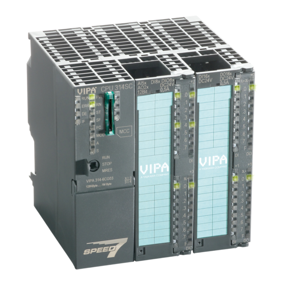
Hardware description VIPA System 300S Structure > Interfaces 4.2 Structure 4.2.1 General CPU 313-5BF23 LEDs of the CPU part Storage media slot (lockable) LEDs of the I/O part Operating mode switch CPU Slot for DC 24V power supply Twisted pair interface for Ethernet PG/OP channel PtP interface MPI interface The components 5 - 8 are under the front flap! - Page 27 VIPA System 300S Hardware description Structure > Interfaces X1: Power supply The CPU has an integrated power supply: The power supply has to be provided with DC 24V. For this serves the double DC 24V slot, that is underneath the flap. Via the power supply not only the internal electronic is provided with voltage, but by means of the backplane bus also the connected modules.
-
Page 28: In-/Output Area Cpu 313-5Bf23
Hardware description VIPA System 300S Structure > In-/Output area CPU 313-5BF23 4.2.3 In-/Output area CPU 313-5BF23 Overview The CPU 313-5BF23 has the following analog and digital in- and output ranges integrated in one casing: Analog Input: 4xU/Ix12Bit, 1xPt100 Analog Output: 2xU/Ix12Bit Digital Input: 24xDC 24V Digital Output: 16xDC 24V, 0.5A Technological functions: 3 channels... - Page 29 VIPA System 300S Hardware description Structure > In-/Output area CPU 313-5BF23 CAUTION! Please regard that the voltage at an output channel is always £ the supply voltage connected to L+. HB140 | CPU-SC | 313-5BF23 | en | 19-01...
- Page 30 Hardware description VIPA System 300S Structure > In-/Output area CPU 313-5BF23 Pin assignment X11: AIO Assignment not connected Voltage measurement channel 0 Current measurement channel 0 Ground channel 0 Voltage measurement channel 1 Current measurement channel 1 Ground channel 1 Voltage measurement channel 2 Current measurement channel 2 Ground channel 2...
- Page 31 VIPA System 300S Hardware description Structure > In-/Output area CPU 313-5BF23 Pin assignment X11: DI Assignment not connected I+2.0 I+2.1 I+2.2 I+2.3 I+2.4 I+2.5 I+2.6 I+2.7 Ground 1M DI 31 ... 40 not connected Status indication X11: DI .0 ..7 –...
- Page 32 Hardware description VIPA System 300S Structure > In-/Output area CPU 313-5BF23 Pin assignment X12: DI Assignment 1L+ Power supply +DC 24V I+0.0 / Channel 0 (A) / Pulse I+0.1 / Channel 0 (B) / Direction I+0.2 / Channel 0 HW gate I+0.3 / Channel 1 (A) / Pulse I+0.4 / Channel 1 (B) / Direction I+0.5 / Channel 1 HW gate...
- Page 33 VIPA System 300S Hardware description Structure > In-/Output area CPU 313-5BF23 Status indication X12: DI – LED (green) Supply voltage available for DI .0 ..7 – LEDs (green) I+0.0 ... I+0.7 I+1.0 ... I+1.7 Starting with ca. 15V the signal "1" at the input is recognized and the according LED is activated Pin assignment X12: DO Assignment...
-
Page 34: Memory Management
Hardware description VIPA System 300S Structure > Slot for storage media Status indication X12: DO 2L+, 3L+ – LED (green) Supply voltage available for DO .0 ..7 – LEDs (green) Q+0.0 ... Q+0.7 Q+1.0 ... Q+1.7 The according LED is on at active output –... -
Page 35: Battery Backup For Clock And Ram
VIPA System 300S Hardware description Structure > Operating mode switch 4.2.6 Battery backup for clock and RAM A rechargeable battery is installed on every CPU to safeguard the contents of the RAM when power is removed. This battery is also used to buffer the internal clock. The rechargeable battery is maintained by a charging circuit that receives its power from the internal power supply and that maintain the clock and RAM for a max. -
Page 36: Leds
Hardware description VIPA System 300S Structure > LEDs 4.2.8 LEDs LEDs CPU Meaning (RUN) (STOP) (SFAIL) (FRCE) (MMC) green yellow yellow yellow Boot-up after PowerON - as soon as the CPU is supplied with 5V, the green PW-LED (Power) is on. Firmware is loaded. - Page 37 VIPA System 300S Hardware description Structure > LEDs Ethernet PG/OP channel Meaning (Link/Activity) (Speed) green green The Ethernet PG/OP channel is physically connected to Ethernet. There is no physical connection. Shows Ethernet activity. flickers The Ethernet interface of the Ethernet PG/OP channel has a transfer rate of 100Mbit.
-
Page 38: Technical Data
Hardware description VIPA System 300S Technical data 4.3 Technical data Please consider with the configuration with the Siemens TIA Portal the number of timer and counters is limited to the maximum possible number of the corresponding Siemens CPU. Order no. 313-5BF23 Type VIPA CPU 313SC... - Page 39 VIPA System 300S Hardware description Technical data Order no. 313-5BF23 Input delay of "0" to "1" 0.1 / 0.35 ms Input delay of "1" to "0" 0.1 / 0.35 ms Number of simultaneously utilizable inputs horizontal con- figuration Number of simultaneously utilizable inputs vertical configu- ration Input characteristic curve IEC 61131-2, type 1...
- Page 40 Hardware description VIPA System 300S Technical data Order no. 313-5BF23 Trigger level Number of operating cycle of relay outputs Switching capacity of contacts Output data size 2 Byte Technical data analog inputs Number of inputs Cable length, shielded 200 m Rated load voltage DC 24 V Reverse polarity protection of rated load voltage...
- Page 41 VIPA System 300S Hardware description Technical data Order no. 313-5BF23 Destruction limit resistance inputs max. 15V Resistance thermometer inputs ü Resistance thermometer ranges Pt100 Operational limit of resistance thermometer ranges +/-0.6% Operational limit of resistance thermometer ranges with Basic error limit thermoresistor ranges +/-0.4% Basic error limit thermoresistor ranges with SFU Destruction limit resistance thermometer inputs...
- Page 42 Hardware description VIPA System 300S Technical data Order no. 313-5BF23 Output voltage ranges -10 V ... +10 V 0 V ... +10 V Operational limit of voltage ranges +/-0.2% Basic error limit voltage ranges with SFU +/-0.1% Destruction limit against external applied voltage max.
- Page 43 VIPA System 300S Hardware description Technical data Order no. 313-5BF23 Load and working memory Load memory, integrated 1024 KB Load memory, maximum 1024 KB Work memory, integrated 256 KB Work memory, maximal 1024 KB Memory divided in 50% program / 50% data ü...
- Page 44 Hardware description VIPA System 300S Technical data Order no. 313-5BF23 Max. potential difference between Mintern and outputs Insulation tested with DC 500 V Command processing times Bit instructions, min. 0.02 µs Word instruction, min. 0.02 µs Double integer arithmetic, min. 0.02 µs Floating-point arithmetic, min.
- Page 45 VIPA System 300S Hardware description Technical data Order no. 313-5BF23 Input I/O address area 1024 Byte Output I/O address area 1024 Byte Input process image maximal 128 Byte Output process image maximal 128 Byte Digital inputs 1016 Digital outputs 1008 Digital inputs central 1016 Digital outputs central...
- Page 46 Hardware description VIPA System 300S Technical data Order no. 313-5BF23 Type of interface RS485 Connector Sub-D, 9-pin, female Electrically isolated ü MP²I (MPI/RS232) DP master DP slave Point-to-point interface 5V DC Power supply max. 90mA, non-isolated 24V DC Power supply max.
- Page 47 VIPA System 300S Hardware description Technical data Order no. 313-5BF23 Routing S7 basic communication S7 communication S7 communication as server S7 communication as client Activation/deactivation of DP slaves Direct data exchange (slave-to-slave communication) DPV1 Transmission speed, min. Transmission speed, max. Number of DP slaves, max.
- Page 48 Hardware description VIPA System 300S Technical data Order no. 313-5BF23 PG/OP channel ü Number of connections, max. Productive connections Point-to-point communication PtP communication ü Interface isolated ü RS232 interface RS422 interface RS485 interface ü Connector Sub-D, 9-pin, female Transmission speed, min. 150 bit/s Transmission speed, max.
-
Page 49: Deployment Cpu 313-5Bf23
VIPA System 300S Deployment CPU 313-5BF23 Start-up behavior Deployment CPU 313-5BF23 5.1 Assembly Ä Chap. 3 ‘Assembly and Information about assembly and cabling: installation guidelines’ page 18 5.2 Start-up behavior Turn on power supply After the power supply has been switched on, the CPU changes to the operating mode the operating mode lever shows. -
Page 50: Addressing
Deployment CPU 313-5BF23 VIPA System 300S Addressing > Addressing Backplane bus I/O devices 5.3 Addressing 5.3.1 Overview To provide specific addressing of the installed peripheral modules, certain addresses must be allocated in the CPU. At the start-up of the CPU, this assigns automatically peripheral addresses for digital in-/output modules starting with 0 and ascending depending on the slot location. - Page 51 VIPA System 300S Deployment CPU 313-5BF23 Addressing > Addressing Backplane bus I/O devices Example for automatic The following sample shows the functionality of the automatic address allocation: address allocation HB140 | CPU-SC | 313-5BF23 | en | 19-01...
-
Page 52: Address Assignment
Deployment CPU 313-5BF23 VIPA System 300S Address assignment 5.4 Address assignment Input range Sub module Default address Access Assignment DI24/DO16 Byte Digital Input I+0.0 ... I+0.7 Byte Digital Input I+1.0 ... I+1.7 Byte Digital Input I+2.0 ... I+2.7 AI5/AO2 Word Analog Input Channel 0 Word Analog Input Channel 1... -
Page 53: Hardware Configuration - Cpu
VIPA System 300S Deployment CPU 313-5BF23 Hardware configuration - I/O modules 5.5 Hardware configuration - CPU Precondition The configuration of the CPU takes place at the Siemens ‘hardware configurator’ . The hardware configurator is part of the Siemens SIMATIC Manager. It serves for project engi- neering. -
Page 54: Hardware Configuration - Ethernet Pg/Op Channel
Deployment CPU 313-5BF23 VIPA System 300S Hardware configuration - Ethernet PG/OP channel Bus extension with IM 360 Maximally 31 modules may be addressed by the CPU 313-5BF23, but per row maximally and IM 361 8 modules are supported. For project engineering the IM 360 of the hardware catalog are to be used as a bus extension during project engineering. -
Page 55: Cpu Parametrization
VIPA System 300S Deployment CPU 313-5BF23 CPU parametrization > Parametrization via Siemens CPU Confirm with [Assign IP configuration]. ð Direct after the assignment the Ethernet PG/OP channel may be reached online by these address data. The value remains as long as it is reassigned, it is over- written by a hardware configuration or an factory reset is executed. -
Page 56: Cpu Parameters
Deployment CPU 313-5BF23 VIPA System 300S CPU parametrization > CPU parameters Description of the parameters of the sub modules ‘DI24/DO16, AI5/AO2’ and ‘Counter’ : Ä Chap. 6 ‘Deployment I/O periphery’ page 83 5.8.2 CPU parameters Supported parameters The CPU does not evaluate each parameter, which may be set at the hardware configu- ration. - Page 57 VIPA System 300S Deployment CPU 313-5BF23 CPU parametrization > CPU parameters Minimum scan cycle time: This parameter is not relevant. Scan cycle load from Communication: This parameter is not relevant. Size of the process image input/output area: This parameter is not relevant. OB85 call up at I/O access error: The preset reaction of the CPU may be changed to an I/O access error that occurs during the update of the process image by the system.
-
Page 58: Project Transfer
Deployment CPU 313-5BF23 VIPA System 300S Project transfer > Transfer via MPI Cyclic interrupts Priority: Here the priorities may be specified according to which the corresponding cyclic inter- rupt is processed. With priority "0" the corresponding interrupt is deactivated. Execution: Enter the time intervals in ms, in which the watchdog interrupt OBs should be pro- cessed. -
Page 59: Transfer Via Ethernet
VIPA System 300S Deployment CPU 313-5BF23 Project transfer > Transfer via Ethernet Terminating resistor A cable has to be terminated with its surge impedance. For this you switch on the termi- nating resistor at the first and the last participant of a network or a segment. Please make sure that the participants with the activated terminating resistors are always power sup- plied. -
Page 60: Transfer Via Memory Card
Deployment CPU 313-5BF23 VIPA System 300S Project transfer > Transfer via memory card Click to ‘PLC è Download’ Download ® the dialog "Select target module" is opened. Select your target module and enter the IP address parameters of the Ethernet PG/OP channel for connection. Provided that no new hardware configura- tion is transferred to the CPU, the entered Ethernet connection is permanently stored in the project as transfer channel. -
Page 61: Accessing The Web Server
VIPA System 300S Deployment CPU 313-5BF23 Accessing the web server 5.10 Accessing the web server Access to the web server There is a web server, which can be accessed via the IP address of the Ethernet PG/OP channel with an Internet browser. At the web page information about the CPU and its connected modules can be found. - Page 62 Deployment CPU 313-5BF23 VIPA System 300S Accessing the web server Card Information Type Product S/N 6BC34010 Size 493617152 bytes Free 492355584 bytes Active Feature Set Information Status Memory Extension present Memory Usage LoadMem 0 / 524288 Bytes CPU: Information to memory con- figuration WorkMemCode 0 / 131072 Bytes...
- Page 63 VIPA System 300S Deployment CPU 313-5BF23 Accessing the web server Info - Overview CPU component: Digitale I/O Info - Expert View Internal Information Slot 202 Module Type 0x4FD30000 Information for support Module Firmware Information PRODUCT VIPA DI24/DO16 Name, firmware version V3.2.9.0 Data - Input data Offset...
- Page 64 Deployment CPU 313-5BF23 VIPA System 300S Accessing the web server Info - Expert View Internal Information Slot 203 Module Type 0x55DD0002 Information for support Module Firmware Information BB000432 V1.1.2.0 PRODUCT VIPA AI5/AO2 Name, firmware version V1.1.2.0 Px000073.pkg Hx000041 V1.6.0.0 Data - AI5 (10byte) Offset Width Value (dec)
- Page 65 VIPA System 300S Deployment CPU 313-5BF23 Accessing the web server Info - Overview CPU component: counter Info - Expert View Internal Information Slot 204 Module Type 0x38C00000 Information for support Module Firmware Information PRODUCT VIPA 3 COUNTER Name, firmware version V3.6.22 Data - Input data (16byte) Offset...
- Page 66 Deployment CPU 313-5BF23 VIPA System 300S Accessing the web server Data - Output data (16byte) Offset Width Value (dec) Value (hex) Info - Overview VBUS - Digital In/Out 16 Data - Input data Offset Width Value (dec) Value (hex) HB140 | CPU-SC | 313-5BF23 | en | 19-01...
- Page 67 VIPA System 300S Deployment CPU 313-5BF23 Accessing the web server Data - Output data Offset Width Value (dec) Value (hex) New Value (hex) HB140 | CPU-SC | 313-5BF23 | en | 19-01...
-
Page 68: Operating Modes
Deployment CPU 313-5BF23 VIPA System 300S Operating modes > Overview 5.11 Operating modes 5.11.1 Overview The CPU can be in one of 4 operating modes: Operating mode STOP Operating mode START-UP Operating mode RUN Operating mode HOLD Certain conditions in the operating modes START-UP and RUN require a specific reaction from the system program. - Page 69 VIPA System 300S Deployment CPU 313-5BF23 Operating modes > Overview Set the breakpoint with ‘Debug è Set Breakpoint’. ð The according command line is marked with a circle. To activate the breakpoint click on ‘Debug è Breakpoints Active’. ð The circle is changed to a filled circle. Bring your CPU into RUN.
-
Page 70: Function Security
Deployment CPU 313-5BF23 VIPA System 300S Operating modes > Function security 5.11.2 Function security The CPUs include security mechanisms like a Watchdog (100ms) and a parameterizable cycle time surveillance (parameterizable min. 1ms) that stop res. execute a RESET at the CPU in case of an error and set it into a defined STOP state. -
Page 71: Overall Reset
VIPA System 300S Deployment CPU 313-5BF23 Overall reset 5.12 Overall reset Overview During the overall reset the entire user memory is erased. Data located in the memory card is not affected. You have 2 options to initiate an overall reset: Overall reset by means of the operating mode switch Overall reset by means of a configuration tool like e.g. -
Page 72: Firmware Update
Deployment CPU 313-5BF23 VIPA System 300S Firmware update 5.13 Firmware update Overview There is the opportunity to execute a firmware update for the CPU and its compo- nents via memory card. For this an accordingly prepared memory card must be in the CPU during the startup. - Page 73 VIPA System 300S Deployment CPU 313-5BF23 Firmware update Via the register ‘General’ the window with hardware and firmware version may be selected. ð Due to software-technical reasons there is something different of the VIPA CPU 313-5BF23 to the CPU 313C from Siemens: VIPA order number (VIPA 313-5BF23) Hardware release (01) Internal hardware version (00)
- Page 74 Deployment CPU 313-5BF23 VIPA System 300S Firmware update Plug the memory card with the firmware files into the CPU. Please take care of the correct plug-in direction of the memory card. Turn on the power supply. ð After a short boot-up time, the alternate blinking of the LEDs SF and FC shows that at least a more current firmware file was found at the memory card.
-
Page 75: Reset To Factory Settings
VIPA System 300S Deployment CPU 313-5BF23 Reset to factory settings 5.14 Reset to factory settings Proceeding With the following proceeding the internal RAM of the CPU is completely deleted and the CPU is reset to delivery state. Please regard that the MPI address is also reset to default 2 and the IP address of the Ethernet PG/OP channel is reset to 0.0.0.0! Ä... -
Page 76: Deployment Storage Media - Mmc, Mcc
Deployment CPU 313-5BF23 VIPA System 300S Deployment storage media - MMC, MCC 5.15 Deployment storage media - MMC, MCC Overview At this slot the following storage media can be plugged: SD respectively MMC (Multimedia card) – External memory card for programs and firmware. MCC - Memory configuration card –... - Page 77 VIPA System 300S Deployment CPU 313-5BF23 Deployment storage media - MMC, MCC You may use the MCC also as "normal" MMC for storing your project. If the memory expansion on the MCC exceeds the maximum extendible memory range of the CPU, the maximum possible memory of the CPU is automatically used. You may determine the recent memory extension and the remaining time after pulling the MCC via the integrated web page.
-
Page 78: Extended Know-How Protection
Deployment CPU 313-5BF23 VIPA System 300S Extended know-how protection 5.16 Extended know-how protection Overview Please note that this functionality is not supported by the Siemens TIA Portal! Besides the "standard" Know-how protection the SPEED7 CPUs from VIPA provide an "extended" know-how protection that serves a secure block protection for accesses of 3. persons. -
Page 79: Cmd - Auto Commands
VIPA System 300S Deployment CPU 313-5BF23 CMD - auto commands 5.17 CMD - auto commands Overview A command file at a memory card is automatically executed under the following condi- tions: CPU is in STOP and memory card is stuck After each PowerON Command file The command file is a text file, which consists of a command sequence to be stored as... -
Page 80: Diagnostic Entries
Deployment CPU 313-5BF23 VIPA System 300S Diagnostic entries Example 1 CMD_START Marks the start of the command sequence (0xE801) LOAD_PROJECT proj.wld Execute an overall reset and load "proj.wld" (0xE805) WAIT1SECOND Wait ca. 1s (0xE803) WEBPAGE Store web page as "webpage.htm" (0xE804) DIAGBUF Store diagnostics buffer of the CPU as "diagbuff.txt"... -
Page 81: Control And Monitoring Of Variables With Test Functions
VIPA System 300S Deployment CPU 313-5BF23 Control and monitoring of variables with test functions 5.19 Control and monitoring of variables with test functions Overview For troubleshooting purposes and to display the status of certain variables you can access certain test functions via the menu item Debug of the Siemens SIMATIC Man- ager. - Page 82 Deployment CPU 313-5BF23 VIPA System 300S Control and monitoring of variables with test functions ‘PLC This test function returns the condition of a selected operand (inputs, outputs, flags, data è Monitor/Modify word, counters or timers) at the end of program execution. This information is obtained Variables’...
-
Page 83: Deployment I/O Periphery
VIPA System 300S Deployment I/O periphery Overview Deployment I/O periphery 6.1 Overview Hardware At the 313-5BF23 the connectors for digital in-/output and technological functions are integrated to a 3-tier casing. Project engineering The project engineering takes place in the Siemens SIMATIC manager as Siemens CPU 313C (6ES7 313-5BF03-0AB0 V2.6). -
Page 84: In-/Output Area Cpu 313-5Bf23
Deployment I/O periphery VIPA System 300S In-/Output area CPU 313-5BF23 6.2 In-/Output area CPU 313-5BF23 Overview The CPU 313-5BF23 has the following analog and digital in- and output ranges integrated in one casing: Analog Input: 4xU/Ix12Bit, 1xPt100 Analog Output: 2xU/Ix12Bit Digital Input: 24xDC 24V Digital Output: 16xDC 24V, 0.5A Technological functions: 3 channels... - Page 85 VIPA System 300S Deployment I/O periphery In-/Output area CPU 313-5BF23 CAUTION! Please regard that the voltage at an output channel is always £ the supply voltage connected to L+. HB140 | CPU-SC | 313-5BF23 | en | 19-01...
- Page 86 Deployment I/O periphery VIPA System 300S In-/Output area CPU 313-5BF23 Pin assignment X11: AIO Assignment not connected Voltage measurement channel 0 Current measurement channel 0 Ground channel 0 Voltage measurement channel 1 Current measurement channel 1 Ground channel 1 Voltage measurement channel 2 Current measurement channel 2 Ground channel 2 Voltage measurement channel 3...
- Page 87 VIPA System 300S Deployment I/O periphery In-/Output area CPU 313-5BF23 Pin assignment X11: DI Assignment not connected I+2.0 I+2.1 I+2.2 I+2.3 I+2.4 I+2.5 I+2.6 I+2.7 Ground 1M DI 31 ... 40 not connected Status indication X11: DI .0 ..7 –...
- Page 88 Deployment I/O periphery VIPA System 300S In-/Output area CPU 313-5BF23 Pin assignment X12: DI Assignment 1L+ Power supply +DC 24V I+0.0 / Channel 0 (A) / Pulse I+0.1 / Channel 0 (B) / Direction I+0.2 / Channel 0 HW gate I+0.3 / Channel 1 (A) / Pulse I+0.4 / Channel 1 (B) / Direction I+0.5 / Channel 1 HW gate...
- Page 89 VIPA System 300S Deployment I/O periphery In-/Output area CPU 313-5BF23 Status indication X12: DI – LED (green) Supply voltage available for DI .0 ..7 – LEDs (green) I+0.0 ... I+0.7 I+1.0 ... I+1.7 Starting with ca. 15V the signal "1" at the input is recognized and the according LED is activated Pin assignment X12: DO Assignment...
- Page 90 Deployment I/O periphery VIPA System 300S In-/Output area CPU 313-5BF23 Status indication X12: DO 2L+, 3L+ – LED (green) Supply voltage available for DO .0 ..7 – LEDs (green) Q+0.0 ... Q+0.7 Q+1.0 ... Q+1.7 The according LED is on at active output –...
-
Page 91: Address Assignment
VIPA System 300S Deployment I/O periphery Address assignment 6.3 Address assignment Input range Sub module Default address Access Assignment DI24/DO16 Byte Digital Input I+0.0 ... I+0.7 Byte Digital Input I+1.0 ... I+1.7 Byte Digital Input I+2.0 ... I+2.7 AI5/AO2 Word Analog Input Channel 0 Word Analog Input Channel 1... -
Page 92: Analog Part
Deployment I/O periphery VIPA System 300S Analog part 6.4 Analog part 313-5BF23 The analog part consists of 4 input, 2 output channels and 1 Pt100 channel. 10byte input and 4byte output data of the process image are used by the analog part. The channels of the module are galvanically separated from the bus via DC/DC transducer and optocouplers. -
Page 93: Access To The I/O Part
VIPA System 300S Deployment I/O periphery Analog part > Access to the I/O part 6.4.1 Access to the I/O part The CPU 313-5BF23 creates in its peripheral area an area for input respectively output data for the modules. Without a hardware configuration the in the following specified default addresses are used. - Page 94 Deployment I/O periphery VIPA System 300S Analog part > Access to the I/O part 6.4.1.1 Address assignment Input range Sub module Default address Access Assignment DI24/DO16 Byte Digital Input I+0.0 ... I+0.7 Byte Digital Input I+1.0 ... I+1.7 Byte Digital Input I+2.0 ... I+2.7 AI5/AO2 Word Analog Input Channel 0...
-
Page 95: Analog Value Representation
VIPA System 300S Deployment I/O periphery Analog part > Analog value representation 6.4.2 Analog value representation Representation of analog Analog values are exclusively processed in a binary format. For this the analog module values transforms every process signal into a digital value and transfers this as word. Resolution Analog value High byte (byte 0) - Page 96 Deployment I/O periphery VIPA System 300S Analog part > Analog value representation Voltage measurement 0 ... 10V Meas. range Voltage Decimal Range Formulas 0 ... 10V > 11.76 32767 7FFFh overflow 11.76V 32511 7EFFh overdrive range 27648 6C00h nominal range 13824 3600h 0000h...
- Page 97 VIPA System 300S Deployment I/O periphery Analog part > Analog value representation Current measurement 4 ... 20mA Output range Current Decimal Range Formulas 4 ... 20mA > 22.81mA 32767 7FFFh overflow 22.81mA 32511 7EFFh overdrive range 20mA 27648 6C00h nominal range 12mA 13824 3600h...
-
Page 98: Analog Part - Wiring
Deployment I/O periphery VIPA System 300S Analog part > Analog part - Wiring 6.4.3 Analog part - Wiring Cables for analog signals For analog signals you should use isolated cables to reduce interference. The cable screening should be grounded at both ends. If there are differences in the potential between the cable ends, there may occur a potential compensating current that could dis- turb the analog signals. -
Page 99: Analog Part - Measurement Principle
VIPA System 300S Deployment I/O periphery Analog part > Analog part - Measurement principle 6.4.4 Analog part - Measurement principle Overview The measurement principle of actual value encoding is used. With a sampling rate of approx. 1.05kHz each millisecond a new value is available in the periphery input word. This value may be read by the user program. -
Page 100: Analog Part - Parameterization
Deployment I/O periphery VIPA System 300S Analog part > Analog part - Parameterization 1 from 16 at 60Hz interference frequency 6.4.5 Analog part - Parameterization Parameter data 13Byte of parameter data are available for the configuration. Parameters of the analog part may be set by means of the AI5/AO2 submodule of the Siemens CPU during hard- ware configuration. -
Page 101: Digital Part
VIPA System 300S Deployment I/O periphery Digital part Byte Bit 7 ... Bit 0 Default 8h: Voltage 0...10V Measurement Analog Input Channel 2 9h: Voltage +/-10V Bit 3 ... 0: Measuring range Bit 7 ... 4: Measuring type Measuring type: Measurement Analog Input Channel 3 0h: deactivated Bit 3 ... - Page 102 Deployment I/O periphery VIPA System 300S Digital part Pin assignment X11: DI Assignment not connected I+2.0 I+2.1 I+2.2 I+2.3 I+2.4 I+2.5 I+2.6 I+2.7 Ground 1M DI 31 ... 40 not connected Status indication X11: DI .0 ..7 – LEDs (green) I+2.0 ...
- Page 103 VIPA System 300S Deployment I/O periphery Digital part Pin assignment X12: DI Assignment 1L+ Power supply +DC 24V I+0.0 / Channel 0 (A) / Pulse I+0.1 / Channel 0 (B) / Direction I+0.2 / Channel 0 HW gate I+0.3 / Channel 1 (A) / Pulse I+0.4 / Channel 1 (B) / Direction I+0.5 / Channel 1 HW gate I+0.6 / Channel 2 (A) / Pulse...
- Page 104 Deployment I/O periphery VIPA System 300S Digital part Status indication X12: DI – LED (green) Supply voltage available for DI .0 ..7 – LEDs (green) I+0.0 ... I+0.7 I+1.0 ... I+1.7 Starting with ca. 15V the signal "1" at the input is recognized and the according LED is activated Pin assignment X12: DO Assignment...
-
Page 105: Access To The I/O Part
VIPA System 300S Deployment I/O periphery Digital part > Access to the I/O part Status indication X12: DO 2L+, 3L+ – LED (green) Supply voltage available for DO .0 ..7 – LEDs (green) Q+0.0 ... Q+0.7 Q+1.0 ... Q+1.7 The according LED is on at active output –... -
Page 106: Digital Part - Parameterization
Deployment I/O periphery VIPA System 300S Digital part > Digital part - Parameterization 6.5.1.1 Address assignment Input range Sub module Default address Access Assignment DI24/DO16 Byte Digital Input I+0.0 ... I+0.7 Byte Digital Input I+1.0 ... I+1.7 Byte Digital Input I+2.0 ... I+2.7 AI5/AO2 Word Analog Input Channel 0... -
Page 107: Counter
VIPA System 300S Deployment I/O periphery Counter > Counter - Fast introduction Inputs Here there are the following adjustment possibilities: Hardware interrupt – A hardware interrupt may be optionally triggered on the rising or falling edge of an input. There are no hardware interrupts available at input I+2.0 ... I+2.7 of the CPU 313-5BF23. - Page 108 Deployment I/O periphery VIPA System 300S Counter > Counter - Fast introduction Open the dialog window "Properties" by a double click to the Count submodule of the CPU. As soon as an operating mode to the corresponding channel is selected, a dialog window for this operating mode is created and displayed and filled with default parameters.
- Page 109 VIPA System 300S Deployment I/O periphery Counter > Counter - Fast introduction For not all inputs are available at the same time, you may set the input assignment for every counter via the parameterization. For each counter the following inputs are avail- able: Channel Pulse input for count signal res.
- Page 110 Deployment I/O periphery VIPA System 300S Counter > Counter - Fast introduction Parameters Description Range of values Default Main count direction None: No restriction of the counting range None None Up: Restricts the up-counting range. Counter starts at 0 or load value, counts in Down (not with positive direction up to the declaration end continuous count)
-
Page 111: Sfb 47 - Count - Counter Controlling
VIPA System 300S Deployment I/O periphery Counter > SFB 47 - COUNT - Counter controlling Parameters Description Range of values Default Characteristics of the The output and the "Comparator" (STS_CMP) No comparison No comparison output status bit are set, dependent on this param- Count ³... - Page 112 Deployment I/O periphery VIPA System 300S Counter > SFB 47 - COUNT - Counter controlling Parameters Name Data type Address Default value Comment (Instance LADDR WORD 300h This parameter is not evaluated. Always the internal I/O periphery is addressed. CHANNEL Channel number SW_GATE BOOL...
- Page 113 VIPA System 300S Deployment I/O periphery Counter > SFB 47 - COUNT - Counter controlling Local data only in instance DB Name Data type Address Default value Comment (Instance RES00 BOOL 26.0 FALSE reserved RES01 BOOL 26.1 FALSE reserved RES02 BOOL 26.2 FALSE...
- Page 114 Deployment I/O periphery VIPA System 300S Counter > SFB 47 - COUNT - Counter controlling Proceeding The deployment of the request interface takes place at the following sequence: Edit the following input parameters: Name Data type Address (DB) Default Comment JOB_REQ BOOL FALSE...
- Page 115 VIPA System 300S Deployment I/O periphery Counter > SFB 47 - COUNT - Counter controlling A value to be read of a read job may be found in JOB_OVAL in the instance DB at address 28. Permitted value range for JOB_VAL Continuous count: Valid range...
-
Page 116: Counter - Functions
Deployment I/O periphery VIPA System 300S Counter > Counter - Functions Valid range Writing pulse duration* 0 ... 510ms *) Only even values allowed. Odd values are automatically rounded. Latch function As soon as during a count process an edge 0-1 is recognized at the "Latch" input of a counter, the recent counter value is stored in the according latch register. - Page 117 VIPA System 300S Deployment I/O periphery Counter > Counter - Functions Count continuously In this operating mode, the counter counts from the load value. When the counter counts forward and reaches the upper count limit and another counting pulse in positive direction arrives, it jumps to the lower count limit and counts from there on.
- Page 118 Deployment I/O periphery VIPA System 300S Counter > Counter - Functions Aborting gate control: Main counting direction forward The counter counts starting with the load value. When the counter reaches the end value -1 in positive direction, it jumps to the load value at the next positive count pulse and the gate is automatically closed.
- Page 119 VIPA System 300S Deployment I/O periphery Counter > Counter - Functions Main counting direction backwards The counter counts backwards starting with the load value. When the counter reaches the end value +1 in negative direction, it jumps to the load value at the next negative count pulse and the gate is automatically closed.
- Page 120 Deployment I/O periphery VIPA System 300S Counter > Counter - Functions Limits Valid value range Lower count limit -2 147 483 648 (-2 Upper count limit +2 147 483 647 (2 Main counting direction forward The counter counts forward starting with the load value. When the counter reaches the end value –1 in positive direction, it jumps to the load value at the next positive count pulse.
-
Page 121: Counter - Additional Functions
VIPA System 300S Deployment I/O periphery Counter > Counter - Additional functions Limits Valid value range Limit value -2 147 483 648 (-2 to +2 147 483 646 (2 Upper count limit +2 147 483 647 (2 6.6.4 Counter - Additional functions Overview The following additional functions may be set via the parameterization for every counter: Gate function... - Page 122 Deployment I/O periphery VIPA System 300S Counter > Counter - Additional functions Gate function The counter is controlled by the internal gate (i gate). The i gate is the result of logic oper- ation of hardware gate (HW gate) and software gate (SW gate), where the HW gate eval- uation may be deactivated by the parameterization.
- Page 123 VIPA System 300S Deployment I/O periphery Counter > Counter - Additional functions At stop function, the counter continues counting with the last recent counter value after gate restart. Gate control abort, inter- How the CPU should react at opening of the SW gate may be set with the parameter ruption Gate function.
- Page 124 Deployment I/O periphery VIPA System 300S Counter > Counter - Additional functions Gate control via SW gate, stopping (HW gate deactivated, gate function: Stop count) SW gate HW gate Reaction Counter edge 0-1 deactivated Continue Gate control via SW/HW gate, canceling (HW gate activated, gate function: Cancel count) SW gate HW gate...
- Page 125 VIPA System 300S Deployment I/O periphery Counter > Counter - Additional functions Characteristics of the You pre-define the behavior of the counter output via the parameterization: output No comparison The output is set as normal output. The SFB input parameter CTRL_DO is effect less. The status bits STS_DO and STS_CMP (Status comparator in the instance DB) remain reset.
- Page 126 Deployment I/O periphery VIPA System 300S Counter > Counter - Additional functions ³ Effect at counter value comparison value Counter value ³ comparison value ® output is set and hysteresis activated Leave hysteresis range ® output is reset Counter value ³ comparison value ® output is set and hysteresis activated Leave hysteresis range, output remains set for counter value ³...
- Page 127 VIPA System 300S Deployment I/O periphery Counter > Counter - Additional functions Counter value = comparison value ® output is set and hysteresis activated Output is reset for leaving hysteresis range and counter value > comparison value Counter value = comparison value ® output is set and hysteresis activated Counter value = comparison value and hysteresis active ®...
-
Page 128: Frequency Measurement
Deployment I/O periphery VIPA System 300S Frequency measurement > Inputs for the frequency measurement 6.7 Frequency measurement 6.7.1 Overview In this operating mode the CPU counts the incoming pulses during a specified integration time and outputs them as frequency value. You can set a value for the integration time between 10ms and 10000ms, in steps of 1 ms. - Page 129 VIPA System 300S Deployment I/O periphery Frequency measurement > Inputs for the frequency measurement Pin assignment X12: DI Assignment 1L+ Power supply +DC 24V I+0.0 / Channel 0 (A) / Pulse I+0.1 / Channel 0 (B) / Direction I+0.2 / Channel 0 HW gate I+0.3 / Channel 1 (A) / Pulse I+0.4 / Channel 1 (B) / Direction I+0.5 / Channel 1 HW gate...
-
Page 130: Parameterization
Deployment I/O periphery VIPA System 300S Frequency measurement > Parameterization Status indication X12: DI – LED (green) Supply voltage available for DI .0 ..7 – LEDs (green) I+0.0 ... I+0.7 I+1.0 ... I+1.7 Starting with ca. 15V the signal "1" at the input is recognized and the according LED is activated 6.7.3 Parameterization Start the Siemens SIMATIC Manager with your project and open the hardware con-... -
Page 131: Sfb 48 - Frequenc - Frequency Measurement
VIPA System 300S Deployment I/O periphery Frequency measurement > SFB 48 - FREQUENC - Frequency measurement Basic parameters Here the interrupts, the counter component should trigger, may be selected. You have the following options: – None: There is no interrupt triggered. –... - Page 132 Deployment I/O periphery VIPA System 300S Frequency measurement > SFB 48 - FREQUENC - Frequency measurement Name Declaration Data type Address Default value Comment (Inst.-DB) STS_GATE OUTPUT BOOL 12.0 FALSE Status of the internal gate MEAS_VAL OUTPUT DINT 14.0 Evaluated frequency JOB_DONE OUTPUT BOOL...
- Page 133 VIPA System 300S Deployment I/O periphery Frequency measurement > SFB 48 - FREQUENC - Frequency measurement Name Data type Address Default Comment (DB) JOB_DONE BOOL 22.0 TRUE New job can be started JOB_ERR BOOL 22.1 FALSE Job error JOB_STAT WORD 24.0 0000h Job error ID...
-
Page 134: Pulse Width Modulation - Pwm
Deployment I/O periphery VIPA System 300S Pulse width modulation - PWM > Overview 6.8 Pulse width modulation - PWM 6.8.1 Overview With the pulse width modulation (PWM) by presetting of time parameters the CPU evalu- ates a pulse sequence with according pulse/break ratio and issues it via the according output channel. - Page 135 VIPA System 300S Deployment I/O periphery Pulse width modulation - PWM > Overview Pin assignment X12: DO Assignment 2L+ Power supply +DC 24V O+0.0 / Channel 0 Output O+0.1 / Channel 1 Output Q+0.2 / Channel 2 Output Q+0.3 Q+0.4 Q+0.5 Q+0.6 Q+0.7...
-
Page 136: Parameterization
Deployment I/O periphery VIPA System 300S Pulse width modulation - PWM > Parameterization Status indication X12: DO 2L+, 3L+ – LED (green) Supply voltage available for DO .0 ..7 – LEDs (green) Q+0.0 ... Q+0.7 Q+1.0 ... Q+1.7 The according LED is on at active output –... - Page 137 VIPA System 300S Deployment I/O periphery Pulse width modulation - PWM > Parameterization Basic parameters Here the interrupts, the counter function should trigger, may be selected. You have the following options: None: There is no interrupt triggered. Process: The counter component triggers a hardware interrupt. Diagnostics and Process: With the CPU the diagnostic interrupt of the digital in-/ output periphery is only supported in connection with "hardware interrupt lost".
-
Page 138: Sfb 49 - Pulse - Pulse Width Modulation
Deployment I/O periphery VIPA System 300S Pulse width modulation - PWM > SFB 49 - PULSE - Pulse width modulation Minimum pulse duration You can set a minimum pulse time for the attenuation of short output pulses/pauses. This suppresses all pulses or pauses shorter than the minimum pulse time. Thus you may filter very small pulses (spikes), which are not noted from the periphery anymore. - Page 139 VIPA System 300S Deployment I/O periphery Pulse width modulation - PWM > SFB 49 - PULSE - Pulse width modulation Parameter Declaration Data type Address Default Comment (Inst.-DB) Value MAN_DO INPUT BOOL FALSE This parameter is not evaluated. SET_DO INPUT BOOL FALSE This parameter is not evaluated.
- Page 140 Deployment I/O periphery VIPA System 300S Pulse width modulation - PWM > SFB 49 - PULSE - Pulse width modulation 02h: Write on-delay Range of values in dependence of the time base: – 1ms: 0 ... 65535 – 0.1ms: 0 ... 65535 –...
- Page 141 VIPA System 300S Deployment I/O periphery Pulse width modulation - PWM > SFB 49 - PULSE - Pulse width modulation Local data only in instance DB Name Data type Address Default Comment (Instance DB) JOB_OVAL DINT 20.0 Output values for read jobs Per channel you may call the SFB in each case with the same instance DB, since the data necessary for the internal operational are stored here.
- Page 142 Deployment I/O periphery VIPA System 300S Pulse width modulation - PWM > SFB 49 - PULSE - Pulse width modulation Call the SFB 49: SW_EN = FALSE JOB_VAL = Enter a value for the minimum pulse duration here JOB_ID = 04h: Write minimum pulse duration for PWM output. JOB_REQ = TRUE (edge 0-1) From JOB_VAL the minimum pulse duration is transmitted to the PWM ð...
- Page 143 VIPA System 300S Deployment I/O periphery Pulse width modulation - PWM > SFB 49 - PULSE - Pulse width modulation Call the SFB 49: SW_EN = FALSE JOB_VAL = Enter a value for the period duration here. JOB_ID = 01h: Write period duration for the 1. pulse train job. JOB_REQ = TRUE (edge 0-1) From JOB_VAL the period duration for the 1.
- Page 144 Deployment I/O periphery VIPA System 300S Pulse width modulation - PWM > SFB 49 - PULSE - Pulse width modulation As soon as JOB_DONE returns TRUE, you can transfer additional pulse train jobs by repeating the steps 1 to 6. By resetting of SW_EN (SW_EN = FALSE) the output is immediately stopped.
- Page 145 VIPA System 300S Deployment I/O periphery Pulse width modulation - PWM > SFB 49 - PULSE - Pulse width modulation Return value JOB_STAT The JOB_STAT return value gives you detailed information in the event of an error. Value Description 0000h no error 0411h Period duration too small...
-
Page 146: Diagnostic And Interrupt
Deployment I/O periphery VIPA System 300S Diagnostic and interrupt > Process interrupt 6.9 Diagnostic and interrupt Overview The parameterization allows you to define the following trigger for a hardware interrupt that may initialize a diagnostic interrupt: Counter function Edge at a digital input Opening the HW gate (at opened SW gate) Closing the HW gate (at opened SW gate) Reaching the comparison value... - Page 147 VIPA System 300S Deployment I/O periphery Diagnostic and interrupt > Process interrupt Local byte Bit 7...0 Bit 0: Gate counter 0 open (activated) Bit 1: Gate counter 0 closed Bit 2: Over-/underflow/end value counter 0 Bit 3: Counter 0 reached comparison value Bit 4: Gate counter 1 open (activated) Bit 5: Gate counter 1 closed Bit 6: Over-/underflow/ end value counter 1...
-
Page 148: Diagnostic Interrupt
Deployment I/O periphery VIPA System 300S Diagnostic and interrupt > Diagnostic interrupt 6.9.2 Diagnostic interrupt Activation Please consider that diagnostic interrupts are enabled only if you have selected one of the technology functions (counting, frequency measure- ment, PWM) and set "Diagnostics+Process interrupt" in the basic param- eters. - Page 149 VIPA System 300S Deployment I/O periphery Diagnostic and interrupt > Diagnostic interrupt Record set 0 Diag- Byte Bit 7...0 nostic incoming Bit 0: set at module failure Bit 1: 0 (fix) Bit 2: set at external error Bit 3: set at channel error Bit 7 ...
- Page 150 Deployment I/O periphery VIPA System 300S Diagnostic and interrupt > Diagnostic interrupt Byte Bit 7...0 Ä ‘Record set 0 Diagnostic 0 ... 3 Content record set 0 ’ page 149 incoming Bit 6 ... 0: Channel type (here 70h) – 70h: Digital input –...
- Page 151 VIPA System 300S Deployment I/O periphery Diagnostic and interrupt > Diagnostic interrupt Byte Bit 7...0 Diagnostic interrupt due to "process interrupt lost" at... Bit 0: ... input I+1.4 Bit 1: 0 (fix) Bit 2: ... input I+1.5 Bit 3: 0 (fix) Bit 4: ...
- Page 152 Deployment I/O periphery VIPA System 300S Diagnostic and interrupt > Diagnostic interrupt Byte Bit 7...0 Ä ‘Record set 0 Diagnostic 0 ... 3 Content record set 0 ’ page 149 incoming Bit 6 ... 0: Channel type (here 70h) – 70h: Digital input –...
- Page 153 VIPA System 300S Deployment I/O periphery Diagnostic and interrupt > Diagnostic interrupt Byte Bit 7...0 Diagnostic interrupt due to "process interrupt lost" at... Bit 0: ... input I+1.4 Bit 1: 0 (fix) Bit 2: ... input I+1.5 Bit 3: 0 (fix) Bit 4: ...
- Page 154 Deployment I/O periphery VIPA System 300S Diagnostic and interrupt > Diagnostic interrupt Byte Bit 7...0 Diagnostic interrupt due to "process interrupt lost" at... Bit 0: ... input I+0.0 Bit 1: 0 (fix) Bit 2: ... input I+0.1 Bit 3: 0 (fix) Bit 4: ...
-
Page 155: Deployment Ptp Communication
VIPA System 300S Deployment PtP communication Fast introduction Deployment PtP communication 7.1 Fast introduction General The CPU has a RS485 interface X3, which is fix set to PtP communication (point to point). PtP functionality – Using the PtP functionality the RS485 interface is allowed to connect via serial point-to-point connection to different source res. -
Page 156: Principle Of The Data Transfer
Deployment PtP communication VIPA System 300S Principle of the data transfer 7.2 Principle of the data transfer RS485 PtP communication The data transfer is handled during runtime by using FC/SFCs. The principle of data transfer is the same for all protocols and is shortly illustrated in the following. Data, which are written into the according data channel by the CPU, is stored in a FIFO send buffer (first in first out) with a size of 2x1024byte and then put out via the interface. -
Page 157: Deployment Of Rs485 Interface For Ptp
VIPA System 300S Deployment PtP communication Deployment of RS485 interface for PtP 7.3 Deployment of RS485 interface for PtP Overview The RS485 interface from the CPU is fix set to PtP communication. Parameterization and communication happens by means of SFCs. Properties RS485 Logical states represented by voltage differences between the two cores of a twisted pair cable... -
Page 158: Parametrization
Deployment PtP communication VIPA System 300S Communication > FC/SFC 217 - SER_SND - Send to PtP Connection RS485 interface Periphery *) For traffic-free data transfer use a terminating resistor of approximately 7.4 Parametrization 7.4.1 FC/SFC 216 - SER_CFG - Parametrization PtP The parametrization happens during runtime deploying the FC/SFC 216 (SER_CFG). -
Page 159: Fc/Sfc 218 - Ser_Rcv - Receive From Ptp
VIPA System 300S Deployment PtP communication Protocols and procedures 7.5.2 FC/SFC 218 - SER_RCV - Receive from PtP This block receives data via the serial interface. Using the FC/SFC 218 SER_RCV after SER_SND with the protocols USS and Modbus the acknowledgement telegram can be read. - Page 160 Deployment PtP communication VIPA System 300S Protocols and procedures 3964 The 3964R procedure controls the data transfer of a point-to-point link between the CPU and a communication partner. The procedure adds control characters to the message data during data transfer. These control characters may be used by the communication partner to verify the complete and error free receipt.
- Page 161 VIPA System 300S Deployment PtP communication Protocols and procedures It is essential: You may connect 1 master and max. 31 slaves at the bus The single slaves are addressed by the master via an address sign in the telegram. The communication happens exclusively in half-duplex operation. After a send command, the acknowledgement telegram must be read by a call of the FC/SFC 218 SER_RCV.
- Page 162 Deployment PtP communication VIPA System 300S Protocols and procedures After a send command, the acknowledgement telegram must be read by a call of the FC/SFC 218 SER_RCV. The request telegrams send by the master and the respond telegrams of a slave have the following structure: Telegram structure Start sign...
-
Page 163: Modbus - Function Codes
VIPA System 300S Deployment PtP communication Modbus - Function codes 7.7 Modbus - Function codes Naming convention Modbus has some naming conventions: Modbus differentiates between bit and word access; bits = "Coils" and words = "Reg- ister". Bit inputs are referred to as "Input-Status" and bit outputs as "Coil-Status". word inputs are referred to as "Input-Register"... - Page 164 Deployment PtP communication VIPA System 300S Modbus - Function codes Code Command Description Read n bits Read n bits of master output area 0x Read n bits Read n bits of master input area 1x Read n words Read n words of master output area 4x Read n words Read n words master input area 3x Write 1 bit...
- Page 165 VIPA System 300S Deployment PtP communication Modbus - Function codes Command telegram Slave address Function code Address 1. bit Number of bits Check sum CRC/LRC 1byte 1byte 1word 1word 1word Respond telegram Slave address Function code Number of Data 1. byte Data 2.
- Page 166 Deployment PtP communication VIPA System 300S Modbus - Function codes Write 1 word 06h Code 06h: Write 1 word to master output area 4x Command telegram Slave address Function code Address word Value word Check sum CRC/LRC 1byte 1byte 1word 1word 1word Respond telegram...
-
Page 167: Modbus - Example Communication
VIPA System 300S Deployment PtP communication Modbus - Example communication 7.8 Modbus - Example communication Overview The example establishes a communication between a master and a slave via Modbus. The following combination options are shown: CPU 31xS as Modbus RTU master CPU 21xSER-1 as Modbus RTU slave Siemens SIMATIC Manager and possibilities for the project transfer Modbus cable connection... - Page 168 Deployment PtP communication VIPA System 300S Modbus - Example communication HB140 | CPU-SC | 313-5BF23 | en | 19-01...
-
Page 169: Winplc7
VIPA System 300S WinPLC7 Installation WinPLC7 8.1 System conception General WinPLC7 is a programming and simulation software from VIPA for every PLC program- mable with Siemens STEP ® 7. This tool allows you to create user applications in FBD, LAD and STL. Besides of a comfortable programming environment, WinPLC7 has an integrated simulator that enables the simulation of your user application at the PC without additional hardware. -
Page 170: Example Project Engineering
WinPLC7 VIPA System 300S Example project engineering > Job definition Activation of the "Profi" Start WinPLC7. version ð A ‘Demo’ dialog is shown Click at [Activate Software]. ð The following dialog for activation is shown: Fill in the following fields: Email-Addr. -
Page 171: Project Engineering
VIPA System 300S WinPLC7 Example project engineering > Project engineering Here it should apply: if value1 = value2 activate output Q 124.0 if value1 > value2 activate output Q 124.1 if value1 < value2 activate output Q 124.2 Precondition You have administrator rights for your PC. WinPLC7 is installed and activated as "Profi"... - Page 172 WinPLC7 VIPA System 300S Example project engineering > Project engineering Establish online access via Ethernet PG/OP channel: Open the CPU-Properties, by double clicking to the CPU at slot 2 in the hardware configurator. Click to the button [Ethernet CP-Properties (PG/OP-channel)]. ð...
- Page 173 VIPA System 300S WinPLC7 Example project engineering > Project engineering Programming of the FC 1 The PLC programming happens by WinPLC7. Close the hardware configurator and return to your project in WinPLC7. The PLC program is to be created in the FC 1. In ‘Project content’...
- Page 174 WinPLC7 VIPA System 300S Example project engineering > Project engineering As requested in the job definition, the corresponding output is activated depending on the comparison of value1 and value2. For each comparison operation a separate network is to be created. The program is to be created as FBD (function block diagram).
- Page 175 VIPA System 300S WinPLC7 Example project engineering > Project engineering The allocation to the corresponding output, here Q 124.0, takes place with the following proceeding: Click to the output at the right side of the operator. Open in the catalog the category ‘Bit logic’ and select the function ‘--[=]’ . The inserting of ‘--[=]’...
- Page 176 WinPLC7 VIPA System 300S Example project engineering > Project engineering Save the FC 1 with ‘File è Save content of focused window’ respectively press [Strg]+[S]. ð After you have programmed the still missing networks, the FC 1 has the fol- lowing structure: Creating the block OB 1 The FC 1 is to be called from the cycle OB 1.
-
Page 177: Test The Plc Program In The Simulator
VIPA System 300S WinPLC7 Example project engineering > Test the PLC program in the Simulator Type in "Call FC 1" and press the [Return] key. ð The FC parameters are automatically displayed and the following parameters are assigned: Save the OB 1 with respectively press [Strg]+[S]. -
Page 178: Transfer Plc Program To Cpu And Its Execution
WinPLC7 VIPA System 300S Example project engineering > Transfer PLC program to CPU and its execution Open the OB 1. Change the value of one variable, save the OB 1 and transfer it to the simulator. ð According to your settings the process image changes immediately. The status of your blocks may be displayed with ‘Block è... - Page 179 VIPA System 300S WinPLC7 Example project engineering > Transfer PLC program to CPU and its execution Choose your CPU, which was provided with TCP/IP address parameters during the hardware configuration and click to [Confirm]. Close the dialog ‘Ethernet properties’ with [OK]. Transfer your project to your CPU with ‘PLC è...
-
Page 180: Configuration With Tia Portal
Configuration with TIA Portal VIPA System 300S TIA Portal - Work environment > General Configuration with TIA Portal 9.1 TIA Portal - Work environment 9.1.1 General General In this chapter the project engineering of the VIPA CPU in the Siemens TIA Portal is shown. -
Page 181: Work Environment Of The Tia Portal
VIPA System 300S Configuration with TIA Portal TIA Portal - Hardware configuration - CPU 9.1.2 Work environment of the TIA Portal Basically, the TIA Portal has the following 2 views. With the button on the left below you can switch between these views: Portal view The ‘Portal view’... - Page 182 Configuration with TIA Portal VIPA System 300S TIA Portal - Hardware configuration - CPU Select the following CPU in the input dialog: SIMATIC S7-300 > CPU 313C (6ES7 313-5BF03-0AB0 V2.6) ð The CPU is inserted with a profile rail. Project area: Device overview: Module Slot...
-
Page 183: Tia Portal - Hardware Configuration - I/O Modules
VIPA System 300S Configuration with TIA Portal TIA Portal - Hardware configuration - I/O modules 9.3 TIA Portal - Hardware configuration - I/O modules Hardware configuration of After the hardware configuration of the CPU place the System 300 modules at the bus in the modules the plugged sequence. -
Page 184: Tia Portal - Hardware Configuration - Ethernet Pg/Op Channel
Configuration with TIA Portal VIPA System 300S TIA Portal - Hardware configuration - Ethernet PG/OP channel 9.4 TIA Portal - Hardware configuration - Ethernet PG/OP channel Overview The CPU has an integrated Ethernet PG/OP channel. This channel allows you to pro- gram and remote control your CPU. - Page 185 VIPA System 300S Configuration with TIA Portal TIA Portal - Hardware configuration - Ethernet PG/OP channel Confirm with [Assign IP configuration]. ð Directly after the assignment the Ethernet PG/OP channel is online reachable using the set IP address data. The value remains as long as it is reassigned, it is overwritten by a hardware configuration or an factory reset is executed.
- Page 186 Configuration with TIA Portal VIPA System 300S TIA Portal - Hardware configuration - Ethernet PG/OP channel Device overview: Module Slot Type PLC... CPU ... DI... DI... DO... DO... DIO... DIO... AI... AI... AO... AO... CP 343-1 CP 343-1 HB140 | CPU-SC | 313-5BF23 | en | 19-01...
-
Page 187: Tia Portal - Vipa-Include Library
VIPA System 300S Configuration with TIA Portal TIA Portal - VIPA-Include library 9.5 TIA Portal - VIPA-Include library Overview The VIPA specific blocks can be found in the "Service" area of www.vipa.com as library download file at Downloads > VIPA LIB. The library is available as packed zip file for the corresponding TIA Portal version. -
Page 188: Tia Portal - Project Transfer
Configuration with TIA Portal VIPA System 300S TIA Portal - Project transfer 9.6 TIA Portal - Project transfer Overview There are the following possibilities for project transfer into the CPU: Transfer via MPI Transfer via Ethernet Transfer via memory card Transfer via MPI Currently the VIPA programming cables for transfer via MPI are not supported. - Page 189 VIPA System 300S Configuration with TIA Portal TIA Portal - Project transfer Transfer via memory card The memory card serves as external storage medium. There may be stored several proj- ects and sub-directories on a memory card. Please regard that your current project is stored in the root directory and has one of the following file names: S7PROG.WLD AUTOLOAD.WLD...
-
Page 190: Appendix
Appendix VIPA System 300S Appendix HB140 | CPU-SC | 313-5BF23 | en | 19-01... - Page 191 VIPA System 300S Appendix Content System specific event IDs................192 Integrated blocks.................... 240 SSL partial list....................244 HB140 | CPU-SC | 313-5BF23 | en | 19-01...
-
Page 192: A System Specific Event Ids
System specific event IDs VIPA System 300S System specific event IDs Ä Chap. 5.18 ‘Diagnostic entries’ page 80 Event IDs Event ID Description 0x115C Manufacture interrupt for EtherCAT / PROFINET IO OB: OB number ZINFO1: Logical address of the slave station that triggered the interrupt ZINFO2: Interrupt type 0: Reserved 1: Diagnostic interrupt (incoming) - Page 193 VIPA System 300S System specific event IDs Event ID Description 0xE005 Internal error - Please contact the hotline! ZINFO1: Not user relevant ZINFO2: Not user relevant ZINFO3: Not user relevant 0xE007 Configured input/output bytes do not fit in the periphery area 0xE008 Internal error - Please contact the hotline! 0xE009...
- Page 194 System specific event IDs VIPA System 300S Event ID Description ZINFO1: Error 4: SSL wrong 5: Sub-SSL wrong 6: Index wrong ZINFO2: SZL-ID ZINFO3: Index 0xE0CC Communication error ZINFO1: Error code 1: Wrong priority 2: Buffer overrun 3: Telegram format error 4: Wrong SSL request (SSL-ID invalid) 5: Wrong SSL request (SSL-Sub-ID invalid) 6: Wrong SSL request (SSL-Index invalid)
- Page 195 VIPA System 300S System specific event IDs Event ID Description 0xE200 Memory card writing finished (Copy Ram2Rom) OB: Not user relevant PK: Not user relevant 0xE210 Memory card reading finished (reload after memory reset) OB: Not user relevant PK: Not user relevant ZINFO1 - Position 0: Not user relevant 0xE21D Memory card reading: Error on reload (after memory reset), error in the block header...
- Page 196 System specific event IDs VIPA System 300S Event ID Description 70: SFB 97: VDB 98: VSDB 99: VFC 100: VSFC 101: VFB 102: VSFB 111: VOB ZINFO3: Block number 0xE300 Internal flash writing completed (copy Ram2Rom) 0xE310 Internal flash reading completed (recharging after battery failure) 0xE400 FSC card was plugged OB: FSC activated from this slot (PK)
- Page 197 VIPA System 300S System specific event IDs Event ID Description 23357: 955-C000M00 24576: 955-C000050 35025: 955-C00MC10 36351: FSC-C000S40 36794: FSC-C000M40 37260: 955-C000S40 37833: 955-C000M40 38050: FSC-C00MC10 41460: 955-C000M50 41526: 955-C0PE040 42655: FSC-C00MC00 47852: 955-C00MC00 48709: FSC-C0PE040 50574: 955-C000M70 52366: 955-C000030 53501: FSC-C000030 58048: FSC-C000020 63411: 955-C000M60...
- Page 198 System specific event IDs VIPA System 300S Event ID Description 4940: FSC-C000S30 5755: 955-C0ME040 6843: FSC-C0NE040 8561: FSC-C000S20 9012: FSC-C000M20 13895: 955-C000060 15618: 955-C000S20 16199: 955-C000M20 17675: FSC-C000S00 18254: FSC-C000M00 20046: FSC-C000040 21053: 955-C000040 22904: 955-C000S00 23357: 955-C000M00 24576: 955-C000050 35025: 955-C00MC10 36351: FSC-C000S40 36794: FSC-C000M40...
- Page 199 VIPA System 300S System specific event IDs Event ID Description ZINFO2: Number of released axes ZINFO3: Number of configured axes 0xE403 FSC can not be activated in this CPU OB: FCS error code PK: FSC source 0: CPU 1: Card ZINFO1: FSC(CRC) 1146: 955-C000070 1736: 955-C0NE040...
- Page 200 System specific event IDs VIPA System 300S Event ID Description 47852: 955-C00MC00 48709: FSC-C0PE040 50574: 955-C000M70 52366: 955-C000030 53501: FSC-C000030 58048: FSC-C000020 63411: 955-C000M60 65203: 955-C000020 ZINFO2: FSC serial number (high word) ZINFO3: FSC serial number (low word) 0xE404 Feature set deleted due to CRC error 0xE405 The trial time of a feature set/memory card has expired OB: Action after the end of the trial time...
- Page 201 VIPA System 300S System specific event IDs Event ID Description 20046: FSC-C000040 21053: 955-C000040 22904: 955-C000S00 23357: 955-C000M00 24576: 955-C000050 35025: 955-C00MC10 36351: FSC-C000S40 36794: FSC-C000M40 37260: 955-C000S40 37833: 955-C000M40 38050: FSC-C00MC10 41460: 955-C000M50 41526: 955-C0PE040 42655: FSC-C00MC00 47852: 955-C00MC00 48709: FSC-C0PE040 50574: 955-C000M70 52366: 955-C000030...
- Page 202 System specific event IDs VIPA System 300S Event ID Description 3903: 955-C000S30 4361: FSC-C000M30 4940: FSC-C000S30 5755: 955-C0ME040 6843: FSC-C0NE040 8561: FSC-C000S20 9012: FSC-C000M20 13895: 955-C000060 15618: 955-C000S20 16199: 955-C000M20 17675: FSC-C000S00 18254: FSC-C000M00 20046: FSC-C000040 21053: 955-C000040 22904: 955-C000S00 23357: 955-C000M00 24576: 955-C000050 35025: 955-C00MC10...
- Page 203 VIPA System 300S System specific event IDs Event ID Description 56: OB 65: DB 66: SDB 67: FC 68: SFC 69: FB 70: SFB 97: VDB 98: VSDB 99: VFC 100: VSFC 101: VFB 102: VSFB 111: VOB ZINFO3: Block number 0xE501 Parser error ZINFO1: Error code...
- Page 204 System specific event IDs VIPA System 300S Event ID Description 0xE503 Inconsistency of code sizes and block sizes in the working memory ZINFO1: Code size ZINFO2: Block size (high word) ZINFO3: Block size (low word) 0xE504 Additional information for CRC error in the working memory ZINFO2: Block address (high word) ZINFO3: Block address (low word) 0xE505...
- Page 205 VIPA System 300S System specific event IDs Event ID Description ZINFO3: Not user relevant DatID: Not user relevant 0xE705 Too many PROFIBUS slaves configured ZINFO1: Diagnostic address of the PROFIBUS master ZINFO2: Number of configured slaves ZINFO3: Number of admissible slaves 0xE710 On-board PROFIBUS/MPI: Bus error occurred PK: Not user relevant...
- Page 206 System specific event IDs VIPA System 300S Event ID Description ZINFO2: Length of the address range ZINFO3: Size of the process image DatID: Address range 0xE801 CMD - auto command: CMD_START recognized and executed 0xE802 CMD - auto command: CMD_End recognized and executed 0xE803 CMD - auto command: WAIT1SECOND recognized and executed 0xE804...
- Page 207 VIPA System 300S System specific event IDs Event ID Description 0xE80E CMD - auto command: SET_NETWORK recognized and executed 0xE80F Internal error - Please contact the hotline! ZINFO3: Status 0: OK 65153: File create error 65185: File writing error 65186: Odd address for reading 0xE810 Internal error - Please contact the hotline! 0xE811...
- Page 208 System specific event IDs VIPA System 300S Event ID Description 0xE901 Checksum error ZINFO1: Not user relevant ZINFO2: Not user relevant DatID: Not user relevant 0xE902 Internal error - Please contact the hotline! ZINFO1: Not user relevant ZINFO2: Not user relevant DatID: Not user relevant 0xE904 PG/OP: Multiple parametrization of a peripheral address...
- Page 209 VIPA System 300S System specific event IDs Event ID Description ZINFO1: Slot DatID: Not user relevant 0xEA02 SBUS: Internal error (internal plugged sub module not recognized) PK: Not user relevant ZINFO1: Slot ZINFO2: Type identifier target ZINFO3: Type identifier DatID: Not user relevant 0xEA03 SBUS: Communication error between CPU and IO controller OB: Operating mode...
- Page 210 System specific event IDs VIPA System 300S Event ID Description 7: Not Connected 8: Unknown DatID: Not user relevant 0xEA04 SBUS: Multiple configuration of a periphery address ZINFO1: Periphery address ZINFO2: Slot ZINFO3: Data width 0xEA05 Internal error - Please contact the hotline! 0xEA07 Internal error - Please contact the hotline! 0xEA08...
- Page 211 VIPA System 300S System specific event IDs Event ID Description PK: Not user relevant ZINFO2: HW slot ZINFO3: Interface type DatID: Not user relevant 0xEA1A SBUS: Error in access to SBUS FPGA address table PK: Not user relevant ZINFO2: HW slot ZINFO3: Table 0: Read 1: Writing...
- Page 212 System specific event IDs VIPA System 300S Event ID Description DatID: Line 0xEA50 PROFINET IO controller: Error in the configuration OB: Not user relevant PK: Not user relevant ZINFO1: Rack/slot of the controller ZINFO2: Device number ZINFO3: Slot at the device DatID: Not user relevant 0xEA51 PROFINET IO controller: There is no PROFINET IO controller at the configured slot...
- Page 213 VIPA System 300S System specific event IDs Event ID Description OB: File number PK: Slot of the controller ZINFO1: Firmware major version ZINFO2: Firmware minor version DatID: Line 0xEA62 Internal error - Please contact the hotline! OB: File number. PK: Slot of the controller ZINFO1: Firmware major version ZINFO2: Firmware minor version DatID: Line...
- Page 214 System specific event IDs VIPA System 300S Event ID Description ZINFO2 - Bit 2: DC parameter invalid ZINFO2 - Bit 3: I device configuration invalid (slot gap) ZINFO2 - Bit 4: MRP configuration invalid (client) 0xEA65 Internal error - Please contact the hotline! PK: Platform 0: none 8: CP...
- Page 215 VIPA System 300S System specific event IDs Event ID Description 1: Dataset error stack 2: Dataset error station ZINFO1: Dataset number ZINFO2: Dataset handle (caller) ZINFO3: Internal error code from PN stack DatID: Device 0xEA69 Internal error - Please contact the hotline! ZINFO1: Minimum version for the FPGA ZINFO2: Loaded FPGA version 0xEA6A...
- Page 216 System specific event IDs VIPA System 300S Event ID Description ZINFO2: Not user relevant ZINFO3: Not user relevant DatID: Not user relevant 0xEA6C PROFINET IO controller: Incorrect Device-ID OB: Operating mode 0: Configuration in operating condition RUN 1: STOP (update) 2: STOP (memory reset) 3: STOP (auto initialization) 4: STOP (internal)
- Page 217 VIPA System 300S System specific event IDs Event ID Description 12: UPDATING 13: DEFECTIVE 14: Error search mode 15: De-energised 253: Process image release in STOP 254: Watchdog 255: Not set PK: Rack/slot ZINFO1: Device ID ZINFO2: Not user relevant ZINFO3: Not user relevant DatID: Not user relevant 0xEA6E...
- Page 218 System specific event IDs VIPA System 300S Event ID Description OB: Operating mode 0: Configuration in operating condition RUN 1: STOP (update) 2: STOP (memory reset) 3: STOP (auto initialization) 4: STOP (internal) 5: STARTUP (cold start) 6: STARTUP (restart/warm start) 7: STARTUP (hot restart) 9: RUN 10: HALT...
- Page 219 VIPA System 300S System specific event IDs Event ID Description 129: PNIO 207: RTA error 218: AlarmAck 219: IODConnectRes 220: IODReleaseRes 221: IOD/IOXControlRes 222: IODReadRes 223: IODWriteRes ZINFO2: ErrorDecode 128: PNIORW: Service Read Write 129: PNIO: Other Service or internal e.g. RPC errors 130: Vendor specific ZINFO3: Error code (PN spec.
- Page 220 System specific event IDs VIPA System 300S Event ID Description 0: INIT 1: STOP 2: READY 3: PAUSE 4: RUN ZINFO1: Filenamehash[0-3] ZINFO2: Filenamehash[4-7] ZINFO3: Line DatID: Current job number 0xEA92 Internal error - Please contact the hotline! OB: Current OB number PK: Core status 0: INIT 1: STOP...
- Page 221 VIPA System 300S System specific event IDs Event ID Description DatID: Not user relevant 0xEA99 Parameter assignment job could not be executed PK: Not user relevant ZINFO1: File version on MMC/SD (if not 0) ZINFO2: File version of the SBUS module (if not 0) ZINFO3: Slot DatID: Not user relevant 0xEAA0...
- Page 222 System specific event IDs VIPA System 300S Event ID Description 6: STARTUP (restart/warm start) 7: STARTUP (hot restart) 9: RUN 10: HALT 11: COUPLING 12: UPDATING 13: DEFECTIVE 14: Error search mode 15: De-energised 253: Process image release in STOP 254: Watchdog 255: Not set ZINFO1: Diagnostic address of the master...
- Page 223 VIPA System 300S System specific event IDs Event ID Description PK: Not user relevant ZINFO1: Error type 1: SDB parser error 2: Configured address already used 3: Mapping error ZINFO2: Slot (0=cannot be determined) DatID: Not user relevant 0xEB04 SLIO-Bus: Multiple configuration of a periphery address ZINFO1: Periphery address ZINFO2: Slot DatID: Input...
- Page 224 System specific event IDs VIPA System 300S Event ID Description 3: Slot invalid 4: Master configuration invalid 5: Master type invalid 6: Slave diagnostic address invalid 7: Slave address invalid 8: Slave module IO configuration invalid 9: Logical address already in use 10: Internal error 11: IO mapping error 12: Error...
- Page 225 VIPA System 300S System specific event IDs Event ID Description 0xEC05 EtherCAT: Check the set DC mode of the YASKAWA Sigma 5/7 drive OB: Operating mode 0: Configuration in operating condition RUN 1: STOP (update) 2: STOP (memory reset) 3: STOP (auto initialization)
- Page 226 System specific event IDs VIPA System 300S Event ID Description 0: Undefined/Unkown 1: Init 2: PreOp 3: Bootstrap 4: SafeOp 8: Op ZINFO1 - Position 8: Previous status 0: Undefined/Unkown 1: Init 2: PreOp 3: Bootstrap 4: SafeOp 8: Op ZINFO2: Diagnostic address of the station ZINFO3: Number of stations, which are not in the same state as the master DatID: Station not available...
- Page 227 VIPA System 300S System specific event IDs Event ID Description DatID: Input address DatID: Output address 0xEC12 EtherCAT: Recurrence slave ZINFO1 - Position 0: New status 0: Undefined/Unkown 1: Init 2: PreOp 3: Bootstrap 4: SafeOp 8: Op ZINFO1 - Position 8: Previous status 0: Undefined/Unkown 1: Init 2: PreOp...
- Page 228 System specific event IDs VIPA System 300S Event ID Description 10: HALT 11: COUPLING 12: UPDATING 13: DEFECTIVE 14: Error search mode 15: De-energised 253: Process image release in STOP 254: Watchdog 255: Not set ZINFO2: Diagnostic address of the master ZINFO3: DC state change 0: DC master out of sync 1: DC slave stations out of sync...
- Page 229 VIPA System 300S System specific event IDs Event ID Description DatID: Output address 0xED12 EtherCAT: Breakdown slave ZINFO1 - Position 0: New status 0: Undefined/Unkown 1: Init 2: PreOp 3: Bootstrap 4: SafeOp 8: Op ZINFO1 - Position 8: Previous status 0: Undefined/Unkown 1: Init 2: PreOp...
- Page 230 System specific event IDs VIPA System 300S Event ID Description 35: Slave station needs to be in SafeOp state 45: Invalid output FMMU configuration 46: Invalid input FMMU configuration 48: Invalid DC Sync configuration 49: Invalid DC Latch configuration 50: PLL error 51: Invalid DC IO error 52: Invalid DC time out error 66: Error in acyclic data exchange Ethernet Over EtherCAT...
- Page 231 VIPA System 300S System specific event IDs Event ID Description 0xED21 EtherCAT: Incorrect bus status change ZINFO1 - Position 0: New status 0: Undefined/Unkown 1: Init 2: PreOp 3: Bootstrap 4: SafeOp 8: Op ZINFO1 - Position 8: Previous status 0: Undefined/Unkown 1: Init 2: PreOp...
- Page 232 System specific event IDs VIPA System 300S Event ID Description 3: Bootstrap 4: SafeOp 8: Op ZINFO2: Diagnostic address of the station ZINFO3: AlStatusCode 0: No error 1: Unspecified error 17: Invalid requested status change 18: Unknown requested status 19: Bootstrap not supported 20: No valid firmware 22: Invalid mailbox configuration 22: Invalid mailbox configuration...
- Page 233 VIPA System 300S System specific event IDs Event ID Description DatID: Station not available DatID: Station available DatID: Input address DatID: Output address 0xED23 EtherCAT: Time out while changing the master state to OP, after CPU has changed to RUN OB: Operating mode 0: Configuration in operating condition RUN 1: STOP (update)
- Page 234 System specific event IDs VIPA System 300S Event ID Description ZINFO2: Diagnostic address of the master 0xED31 EtherCAT: Overflow of the interrupt queue ZINFO2: Diagnostic address of the master 0xED40 Bus cycle time infringement occurred ZINFO1: Logical address of the IO system 0xED50 EtherCAT: Distributed clocks (DC) in sync OB: Operating mode...
- Page 235 VIPA System 300S System specific event IDs Event ID Description 7: STARTUP (hot restart) 9: RUN 10: HALT 11: COUPLING 12: UPDATING 13: DEFECTIVE 14: Error search mode 15: De-energised 253: Process image release in STOP 254: Watchdog 255: Not set ZINFO1 - Position 0: New status 0: Undefined/Unkown 1: Init...
- Page 236 System specific event IDs VIPA System 300S Event ID Description 33: Slave station needs to be in INIT state 34: Slave station needs to be in PreOp state 35: Slave station needs to be in SafeOp state 45: Invalid output FMMU configuration 46: Invalid input FMMU configuration 48: Invalid DC Sync configuration 49: Invalid DC Latch configuration...
- Page 237 VIPA System 300S System specific event IDs Event ID Description 0xED63 EtherCAT: Diagnostic buffer CP: Error in the response to an INIT command OB: EtherCAT station address (high byte) PK: EtherCAT station address (low byte) ZINFO1: Error type 0: Not defined 1: No response 2: Validation error 3: INIT command failed, requested station could not be reached...
- Page 238 System specific event IDs VIPA System 300S Event ID Description ZINFO2: Not user relevant ZINFO3: Not user relevant DatID: Not user relevant 0xEE01 Internal error - Please contact the hotline! ZINFO3: SFB number 0xEEEE CPU was completely deleted, since after PowerON the start-up could not be finished 0xEF00 Internal error - Please contact the hotline! DatID: Not user relevant...
- Page 239 VIPA System 300S System specific event IDs Event ID Description 29: The component actively disconnected the system connection to the CPU 31: Inconsistency of the component data base by loading SDB xxxx by the rack component (SDB type 0x3100) 32: Periphery enabled by S7-CPU 33: Periphery disabled by S7-CPU 34: Component STOP due to switch actuation 35: Component STOP due to invalid configuration...
-
Page 240: B Integrated Blocks
Integrated blocks VIPA System 300S Integrated blocks More information about this may be found in the manual "SPEED7 Oper- ation List" from VIPA. Name Description OB 1 CYCL_EXC Program Cycle OB 10 TOD_INT0 Time-of-day Interrupt OB 20 DEL_INT0 Time delay interrupt OB 28 CYC_INT_250us Cyclic interrupt... - Page 241 VIPA System 300S Integrated blocks Name Description SFB 14 Remote CPU read SFB 15 Remote CPU write SFB 31 NOTIFY8P Messages without acknowledge display (8x) SFB 32 DRUM Realize a step-by-step switch SFB 33 ALARM Messages with acknowledgement display SFB 34 ALARM_8 Messages without associated values (8x) SFB 35...
- Page 242 Integrated blocks VIPA System 300S Name Description SFC 25 COMPRESS Compressing the User Memory SFC 28 SET_TINT Set time-of-day interrupt SFC 29 CAN_TINT Cancel time-of-day interrupt SFC 30 ACT_TINT Activate time-of-day interrupt SFC 31 QRY_TINT Query time-of-day interrupt SFC 32 SRT_DINT Start time-delay interrupt SFC 33...
- Page 243 VIPA System 300S Integrated blocks Name Description SFC 71 LOG_GEO Determining the slot belonging to a logical address SFC 75 SET_ADDR Set PROFIBUS MAC address SFC 81 UBLKMOV Copy data area without gaps SFC 101 HTL_RTM Handling runtime meters SFC 102 RD_DPARA Reading predefined parameters SFC 105...
-
Page 244: Cssl Partial List
SSL partial list VIPA System 300S SSL partial list More information about this may be found in the manual "SPEED7 Oper- ation List" from VIPA. SSL-ID SSL partial list xy11h Module identification xy12h CPU characteristics xy13h User memory areas xy14h System areas xy15h Block Types...
Need help?
Do you have a question about the SPEED7 CPU-SC 313-5BF23 and is the answer not in the manual?
Questions and answers