
Related Manuals for YASKAWA SGDH Sigma-II Series


Summary of Contents for YASKAWA SGDH Sigma-II Series
- Page 1 YASKAWA Series SGDH DeviceNet INTERFACE MODULE USER'S MANUAL MODEL: JUSP-NS300 YASKAWA MANUAL NO. SIE-C718-6B...
-
Page 2: Safety Information
Yaskawa. No patent liability is assumed with respect to the use of the information contained herein. Moreover, because Yaskawa is constantly striving to improve its high-quality products, the information contained in this manual is subject to change without notice. -
Page 3: Visual Aids
Visual Aids The following aids are used to indicate certain types of information for easier reference. Indicates application examples. EXAMPLE " Indicates supplemental information. INFO Indicates important information that should be memorized. IMPORTANT z Explains difficult to understand terms and terms that have not been explained before. TERMS... - Page 4 OVERVIEW OVERVIEW Safety Information ......... . Visual Aids .
- Page 5 7 Using the NSxxx Setup Tool ....7 -1 7.1 Connection and Installation ......7 -2 7.2 How to Use .
-
Page 6: Table Of Contents
TABLE OF CONTENTS TABLE OF CONTENTS Safety Information ..........Visual Aids . - Page 7 3.5.3 Precautions for Wiring DeviceNet Cables ....... . 3 -18 3.5.4 Grounding .
- Page 8 TABLE OF CONTENTS 5.4.6 Positioning Command ..........5 -36 5.4.7 External Positioning .
- Page 9 Using the NSxxx Setup Tool 7.1 Connection and Installation ....... . . 7 -2 7.1.1 Connecting the NS300 Module .
- Page 10 TABLE OF CONTENTS Alarm and Warning Codes C.1 Alarm Codes ..........C -2 C -5 C.2 Warning Codes...
-
Page 11: Overview
Overview J About this Manual This manual provides the following information for the Σ-ΙΙ Series SGMjH/SGDH Servodrives with a JUSP-NS300 DeviceNet Interface Module (hereinafter called the NS300 Module) mounted. The NS300 Module is an Application Module. D Procedures for installing and wiring the NS300 Module D Specifications and methods for SERVOPACK DeviceNet communications D Procedures for setting parameters D Information on the NSxxx Setup Tool... -
Page 12: Using This Manual
Using This Manual Using This Manual J Intended Audience This manual is intended for the following users. D Those designing Servodrive systems using DeviceNet. D Those designing Σ-II Series Servodrive systems. D Those installing or wiring Σ-II Series Servodrives. D Those performing trial operation or adjustments of Σ-II Series Servodrives. D Those maintaining or inspecting Σ-II Series Servodrives. -
Page 13: Safety Precautions
Safety Precautions The following precautions are for checking products upon delivery, installation, wiring, operation, maintenance and inspections. J Checking Products upon Delivery CAUTION D Always use the servomotor and SERVOPACK in one of the specified combinations. Not doing so may cause fire or malfunction. J Installation CAUTION D Never use the products in an environment subject to water, corrosive gases, inflammable gases,... - Page 14 Safety Precautions J Operation WARNING D Never touch any rotating motor parts while the motor is running. Doing so may result in injury. CAUTION D Conduct trial operation on the servomotor alone with the motor shaft disconnected from machine to avoid any unexpected accidents. Not doing so may result in injury.
- Page 15 The edition number appears on the front and back covers. S If the manual must be ordered due to loss or damage, inform your nearest Yaskawa representa- tive or one of the offices listed on the back of this manual.
-
Page 16: Checking Products And Part Names
Checking Products and Part Names This chapter describes the procedure for checking Σ-II Series products and the NS300 Module upon delivery. It also describes the names of product parts. 1.1 Checking Products on Delivery ..1 -2 1.2 Product Part Names . -
Page 17: Checking Products On Delivery
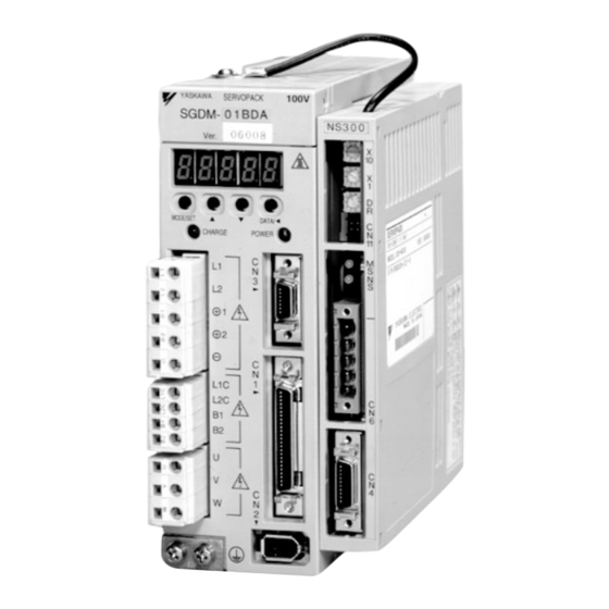
“E” as shown below to support the NS300 Mod- ule. SGDH-jjjE-j If any of the above items are faulty or incorrect, contact your Yaskawa sales representative or the deal- er from whom you purchased the products. J External Appearance and Nameplate Example... -
Page 18: Product Part Names
1.2 Product Part Names J Model Number NS300 Module JUSP − NS30 0 SERVOPACK Peripheral Device Design Revision Order Type of device: NS30: DeviceNet Interface Module 1.2 Product Part Names The following diagram illustrates the part names of the NS300 Module. Ground wire: Connect to the terminal marked “G”... -
Page 19: Mounting The Ns300 Module
By mounting NS300 Module, the SGDH SERVOPACK can be used in a DeviceNet network. Use the following procedure to ensure NS300 Modules are mounted correctly. 1. Remove the connector cover from the CN10 connector on the SERVOPACK. CN10 SERVOPACK YASKAWA SGDH− Connector cover MODE/SET DATA/... - Page 20 1.3 Mounting the NS300 Module 2. Mount the NS300 Module on the SERVOPACK. CN10 Connector (for connection to SERVOPACK) YASKAWA SERVOPACK SGDH− Ver. CHARGE POWER 3. For grounding, connect a ground wire of the NS300 Module to the point marked “G” on the SERVOPACK.
- Page 21 Checking Products and Part Names When the NS300 Module has been mounted correctly, the SERVOPACK will appear as shown in the following diagram. 1 -6...
-
Page 22: Installation
Installation This chapter describes precautions for Σ-II Series product installation. The SGDH SERVOPACKs are base-mounted servo amplifiers. Incorrect installation will cause problems. Always observe the installation precau- tions shown in this chapter. 2.1 Storage Conditions ....2 -2 2.2 Installation Site . -
Page 23: Storage Conditions
Installation 2.1 Storage Conditions Store the SERVOPACK within the following temperature range when it is stored with the power cable disconnected. Temperature range: −20 to 85°C Σ-II Series SGDH SERVOPACK with NS300 Module mounted 2.2 Installation Site Take the following precautions at the installation site. Situation Installation Precaution Installation in a Control... -
Page 24: Orientation
2.3 Orientation 2.3 Orientation Install the SERVOPACK perpendicular to the wall as shown in the figure. The SERVOPACK must be oriented this way because it is designed to be cooled by natural convection or cooling fan. Secure the SERVOPACK using 2 to 4 mounting holes. The number of holes depends on the SER- VOPACK capacity. -
Page 25: Installation
Installation 2.4 Installation Follow the procedure below to install multiple SERVOPACKs side by side in a control panel. 50 mm min. NS300 NS300 NS300 NS300 50 mm min. 10 mm min. 30 mm min. J SERVOPACK Orientation Install the SERVOPACK perpendicular to the wall so that the front panel (containing connectors) faces outward. -
Page 26: Connectors
Connectors This chapter describes the procedure used to connect Σ-II Series products to peripheral devices when NS300 Module is mounted and gives typical ex- amples of I/O signal connections. 3.1 Connecting to Peripheral Devices ..3 -2 3.1.1 Single-phase (100 V or 200 V) Main Circuit Specifications... - Page 27 Connectors 3.1 Connecting to Peripheral Devices This section provides examples of standard Σ-II Series product connections to peripheral devices. It also briefly explains how to connect each peripheral device. 3 -2...
- Page 28 3.1.1 Single-phase (100 V or 200 V) Main Circuit Specifications Can be connected to DeviceNet Master. Host Controller MEMOCON GL120/130, MP920 Power supply Molded-case Circuit (Manufactured by Yaskawa) Single-phase 200 VAC Breaker (MCCB) R S T Protects the pow- Digital Operator er line by shutting...
-
Page 29: Three-Phase, 200-V Main Circuit Specifications
Three-phase 200 VAC R S T Molded-case Circuit Breaker (MCCB) Protects the pow- er line by shutting MEMOCON GL120/130, MP920 the circuit OFF (Manufactured by Yaskawa) when overcurrent is detected. Molded-case circuit breaker Digital Operator JUSP-OP02A-2 Allows the user to set... -
Page 30: Three-Phase, 400-V Main Circuit Specifications
100-VAC or 200-VAC power supply. 24-VDC power supply for servomo- tors with 24-VDC brakes. MEMOCON GL120/130, MP920 Power supply Molded-case Circuit (Manufactured by Yaskawa) Three-phase 400 VAC Breaker (MCCB) R S T Protects the pow- er line by shutting the circuit OFF... -
Page 31: Servopack Internal Block Diagrams
Connectors 3.2 SERVOPACK Internal Block Diagrams The following sections show an internal block diagram for the SERVOPACK with the NS300 Mod- ule. 30 to 400 W 200-V and 30 to 200 W 100-V Models Single-phase +10 % 200 to 230 V −15% (50/60Hz) PM−1... - Page 32 3.3 I/O Signals 3.3 I/O Signals This section describes I/O signals for the SERVOPACK with the NS300 Module. 3.3.1 Connection Example of I/O Signal Connector (CN1) The following diagram shows a typical example of I/O signal connections. SGDH SERVOPACK BAT + Alarm code output Backup battery ALO1...
-
Page 33: I/O Signals Connector (Cn1)
Connectors 3.3.2 I/O Signals Connector (CN1) 3.3.2 I/O Signals Connector (CN1) The following diagram shows the layout of CN1 terminals. J CN1 Terminal Layout Positioning 26 /COIN- 26 /COIN- complete complete output /BK+ Brake inter- (Note 3) lock output /BK- Brake inter- Brake inter −... -
Page 34: I/O Signal Names And Functions
3.3 I/O Signals 3.3.3 I/O Signal Names and Functions The following section describes SERVOPACK I/O signal names and functions. J Input Signals Signal Name Pin No. Function Common /DEC Zero point return deceleration NS: Deceleration LS for zero point return connected. P-OT Forward run prohibited Overtravel prohibited: Stops servomotor when movable part travels... -
Page 35: Interface Circuits
Connectors 3.3.4 Interface Circuits 3.3.4 Interface Circuits The following diagram shows an example of connections between a host controller and the I/O signal for a SERVOPACK. J Sequence Input Circuit Interface The sequence input circuit interface connects through a relay or open-collector transistor circuit. Select a low-current relay, otherwise a faulty contact will result. - Page 36 3.3 I/O Signals D Connecting to a Photocoupler Output Circuit Photocoupler output circuits are used for servo alarm, servo ready, and other sequence out- put signal circuits. Connect a photocoupler output circuit through a relay or line receiver circuit. 5 to 24 VDC 5 to 12 VDC Relay SERVOPACK...
-
Page 37: Connection Terminal Layout
Connectors 3.4.1 Connection Terminal Layout 3.4 I/O Signal Connections for NS300 Modules (CN4) The CN4 on an NS300 Module is used for I/O signal and fully-closed encoder signal connections. 3.4.1 Connection Terminal Layout The terminal layout and specifications for the CN4 are outlined below. J CN4 Terminal Layout Pin No. -
Page 38: I/O Signal Interface Circuits
3.4 I/O Signal Connections for NS300 Modules (CN4) 3.4.2 I/O Signal Interface Circuits The following diagram shows an example of connections between a host controller and the I/O signals for an NS300 Module. J Sequence I/O Circuit Interface The sequence input circuit interface connects through a relay or open-collector transistor circuit. Select a low-current relay, otherwise a faulty contact will result. -
Page 39: Fully-Closed Encoder Connection Example
Connectors 3.4.3 Fully-closed Encoder Connection Example 3.4.3 Fully-closed Encoder Connection Example The following diagram shows a connection example for a fully-closed encoder. External PG NS300 1, 2, 3 PG 0V External : Shield. power supply 3 -14... -
Page 40: Connections For Devicenet Communications
3.5 Connections for DeviceNet Communications 3.5 Connections for DeviceNet Communications This section describes the connection and wiring of connectors for DeviceNet communications. 3.5.1 DeviceNet Communications Connection Example The following diagram shows an example of connections between a host controller and an NS300 Module (CN6) using DeviceNet communications cables. - Page 41 Connectors 3.5.1 DeviceNet Communications Connection Example Terminator Both ends of the trunk line must connect to terminating resistance to decrease signal reflection and ensure stable network communications. Communications Power Supply The communications connector of each node must be provided with a communications power supply through the communications cable for DeviceNet communications.
-
Page 42: Devicenet Communications Connectors (Cn6)
3.5 Connections for DeviceNet Communications J Branching from Drop Lines There are three methods that can be used to branch from drop lines. Single Branching Drop line Drop line T-Branch Adapter Drop line NS300 Module Branching to Three Drop Lines Drop line Drop line T-Branch... -
Page 43: Precautions For Wiring Devicenet Cables
Connectors 3.5.3 Precautions for Wiring DeviceNet Cables J Connector Pin Arrangement The connector pin arrangement is as shown below. Pin No. Symbol Detail and Code 0 (24 V) 0 V external communications power supply CAN L CAN bus line dominant L SHIELD Shield CAN H... - Page 44 3.5 Connections for DeviceNet Communications The maximum network length is determined by the type of cable, as shown in the following table. Baud Rate (Kbps) Maximum Network Length (m) Thick Cable Thin Cable The line connecting two nodes located farthest from each other can use both thick and thin cables provided that INFO the length of each cable satisfies the conditions in the following table.
- Page 45 Connectors 3.5.3 Precautions for Wiring DeviceNet Cables The following example is for a baud rate of 500 Kbps. T-Branch Adapter Terminator (with terminator) Node Node Node Node Node Node Trunk line Drop line Node T-Branch Adapter Node The above example must satisfy the following conditions. D a ≦...
-
Page 46: Grounding
3.5 Connections for DeviceNet Communications J Location of Power Supply The following two types of configuration are possible for the location of the power supply. Nodes on Both Sides of the Power Supply Power Supply Tap or T-Branch Adapter NS300 NS300 NS300 NS300... - Page 47 Connectors 3.5.4 Grounding J Power Supply without Ground Power Supply Tap CAN H Communications Shield cable CAN L V− V− Communications power supply Ground to a resistance of 100 Ω or less. If more than one communications power supply is used, ground only the power supply that is located closest to the middle of the network through the shield wire.
-
Page 48: Parameter Settings
Parameter Settings This chapter provides an outline and details of NS300 parameters. 4 -2 4.1 Parameters ......4 -2 4.1.1 Outline of Parameters . -
Page 49: Parameters
Parameter Settings 4.1.2 Parameter Types 4.1 Parameters 4.1.1 Outline of Parameters Parameters is the name given to the user constants that are required as the settings used to oper- ate the NS300 Module. You must set the optimum values for parameters according to the NS300 Module and the machine to which the SGDH is mounted. -
Page 50: Editing Parameters
4.1 Parameters 4.1.3 Editing Parameters You can edit parameters using the following methods. Table 4.2 Methods of Editing Parameters Tools Methods Remarks NSxxx Setup Select Option Parameter List from the All changed parameters are stored in Tool Parameter Menu to read all the NS300 RAM, so they are erased when the Module parameters. -
Page 51: Parameter Tables
Parameter Settings 4.2.2 Zero Point Return Parameters 4.2 Parameter Tables The following tables list the parameters. If using the NSxxx Setup Tool or reading/writing using a command message, edit parameters using Pnjjj. If editing via DeviceNet explicit messages, edit using the object number and attribute number. -
Page 52: Machine System And Peripheral Device Parameters
4.2 Parameter Tables Object Attribute Name Range Units Effective Default Type Timing Value 0x64 Pn809 Zero Point Offset −99,999,999 to Reference Immediate 0 99,999,999 units Pn80A Accel/Decel Time for 1 to 10,000 Immediate 100 Zero Point Return Note: 1. For reference unit details, refer to 4.3.1 Unit Parameters. 2. -
Page 53: Speed, Acceleration, And Deceleration Parameters
Parameter Settings 4.2.4 Speed, Acceleration, and Deceleration Parameters 4.2.4 Speed, Acceleration, and Deceleration Parameters A table of speed, acceleration, and deceleration parameters is shown below. Object Attribute Name Range Units Effective Default Type Timing Value 0x64 Pn821 Feed Speed for 1 to 240,000 1000 Immediate 24,000... - Page 54 4.2 Parameter Tables Object Attribute Name Range Units Effective Default Type Timing Value 0x64 Pn836 Accel/Decel Type for 0, 1, 2, 3 Immediate 0 Constant Feed Pn840 Time Constant for 4 to 1,000 Immediate 25 Exponential Accel/Decel Pn841 Bias Speed for 0 to 240,000 1000 Immediate 0...
-
Page 55: Positioning Parameters
Parameter Settings 4.2.6 Multi-speed Positioning Parameters 4.2.5 Positioning Parameters The positioning parameter table is shown below. Object Attribute Name Range Units Effective Default Type Timing Value 0x64 Pn850 Positioning Deadband 0 to 10,000 Reference Immediate 5 units Pn851 Positioning Timeout 0 to 100,000 Immediate 0 Pn852... - Page 56 4.2 Parameter Tables Object Attribute Name Range Units Effective Default Type Timing Value 0x64 #115 Pn865 Speed Switching Position 3 0 to 99,999,999 Reference Immediate units #116 Pn866 Speed Switching Position 4 0 to 99,999,999 Reference Immediate units #117 Pn867 Speed Switching Position 5 0 to 99,999,999 Reference Immediate...
- Page 57 Parameter Settings 4.2.6 Multi-speed Positioning Parameters Object Attribute Name Range Units Effective Default Type Timing Value 0x64 #133 Pn877 Switching Speed 5 1 to 240,000 1000 Immediate 24,000 reference units/min #134 Pn878 Switching Speed 6 1 to 240,000 1000 Immediate 24,000 reference units/min...
-
Page 58: Notch Output Parameters
4.2 Parameter Tables 4.2.7 Notch Output Parameters The notch output parameter table is shown below. Object Attribute Name Range Units Effective Default Type Timing Value 0x64 #160 Pn890 Notch Signal Output 0, 1 − Immediate Position Setting #161 Pn891 Notch Signal Output 0 to 3 −... -
Page 59: Parameter Details
Parameter Settings 4.3.1 Unit Parameters 4.3 Parameter Details 4.3.1 Unit Parameters The unit for performing positioning using a NS300 Module is determined by the following two parameters. Object Attribute Name Range Units Effective Default Type Timing Value 0x64 Pn810 Electronic gear 1 to 10,000,000 Power-up (numerator) -
Page 60: System Example
4.3 Parameter Details J Electronic Gear Settings When Using a Ball Screw If using a ball screw, first check the following specifications. D Number of Encoder pulses D Gear ratio D Ball screw pitch System Example The following system example shows the formulas when the reference unit is set to 0.001 mm. SGDH NS300 0.001 mm... - Page 61 Parameter Settings 4.3.1 Unit Parameters J Electronic Gear Settings when Using a Rotary Table If using a rotary table, first check the following specifications. D Number of Encoder pulses D Gear ratio System Example The following system example shows the formulas when the reference unit is set to 0.001°. SGDH NS300 0.001°...
-
Page 62: Zero Point Return Parameters
4.3 Parameter Details 4.3.2 Zero Point Return Parameters J Zero Point Return Types The following four types of zero point return are supported when the incremental detection system is used. Type 0 This zero point return type returns to the zero point using the deceleration limit switch signal (DEC signal) and the phase C pulse of the encoder. - Page 63 Parameter Settings 4.3.2 Zero Point Return Parameters Type 1 This zero point return type returns to the zero point using the zero point signal (ZERO signal). The outline of the operation is as follows: 1. The axis travels in the direction specified as the zero point direction in the Zero Point Return Function Selection (Pn801) at the Zero Point Return Approach Speed (Pn803).
- Page 64 4.3 Parameter Details Zero point return feed speed (Pn802) Zero point return approach speed (Pn803) Speed Zero point return creep speed (Pn804) Zero point return final travel distance (Pn805) Time Dog width Deceleration limit switch signal Zero point signal Machine coordinate system zero point Zero point area Type 3...
- Page 65 Parameter Settings 4.3.2 Zero Point Return Parameters When the setting for the Zero Point Return Final Travel Distance (Pn805) is small (when the distance INFO is shorter than the distance required for the deceleration from approach speed), the axis will travel past the zero point and then return to it from the other direction.
- Page 66 4.3 Parameter Details Zero Point Return Function Selection (Object: 0x64, Attribute: #11; Pn801) The zero point return function selection has the following bit settings. Name Description Zero Point Return Direction Setting* 0: Positive direction 1: Negative direction Deceleration Limit Switch Signal Set- 0: Enabled on Low ting 1: Enabled on High...
- Page 67 Parameter Settings 4.3.2 Zero Point Return Parameters D X = | Zero point − Current position | ≦ Pn806 Zero point Current position Position Pn806 Pn806 Zero Point Offset (Object: 0x64, Attribute: #17; Pn809) The system automatically writes to the Zero Point Offset the value of the offset from the zero point on the encoder when the zero point setting in the absolute value detection system has been completed.
-
Page 68: Machine System And Peripheral Devices
4.3 Parameter Details 4.3.3 Machine System and Peripheral Devices The details of parameters relating to the machine system and peripheral devices are shown be- low. Coordinate Type (Object: 0x64, Attribute: #32; Pn812) Use the Coordinate Type to set whether to use the NS300 Module as a linear axis or rotary axis. Pn812 Description The linear axis is designated. - Page 69 Parameter Settings 4.3.3 Machine System and Peripheral Devices Machine Function Selection (Object: 0x64, Attribute: #38; Pn818) Use the Machine Function Selection to set whether or not to use the software limit functions and the backlash compensation functions. Description 0: Software Limit is disabled. 1: Software Limit is enabled.
- Page 70 4.3 Parameter Details Emergency Stop Signal Function Selection (Object: 0x64, Attribute: #41: Pn81B) Use the Emergency Stop Signal Function Selection to set whether or not to use the emergency stop function and to set the polarity of the signal. Name Description Enable/disable 0: Disabled...
-
Page 71: Speed, Acceleration, And Deceleration
Parameter Settings 4.3.4 Speed, Acceleration, and Deceleration 4.3.4 Speed, Acceleration, and Deceleration J Acceleration and Deceleration Patterns The following acceleration and deceleration patterns are possible by combining acceleration/ deceleration types (Pn826 or Pn836) and filters (Pn829). Acceleration/Deceleration Type (Pn826 or Pn836) −... - Page 72 4.3 Parameter Details Single-step Linear Acceleration/Deceleration with Constant Acceleration/Deceleration For Single-step Linear Acceleration/Deceleration with Constant Acceleration/Deceleration, the acceleration/deceleration is determined by two parameters: the Maximum Feed Speed and the Acceleration Time for Positioning. The time T required to reach the Feed Speed for Positioning can be calculated as follows: T [ms] = Pn822 ×...
- Page 73 Parameter Settings 4.3.4 Speed, Acceleration, and Deceleration Double-step Linear Acceleration/Deceleration with Constant Acceleration/Deceleration For Double-step Acceleration/Deceleration, the acceleration/deceleration will change when the Switch Speed for Second Acceleration/Deceleration is reached. The acceleration/decel- eration for step 1 is determined by two parameters: the Maximum Feed Speed and the Accel- eration Time for Positioning.
- Page 74 4.3 Parameter Details Asymmetric Linear Acceleration/Deceleration with Constant Acceleration/Deceleration For Asymmetric Linear Acceleration/Deceleration, the acceleration and deceleration can be set separately in Single-step Linear Acceleration/Deceleration. For example, for deceleration, the time T required to stop from the Feed Speed for Positioning can be calculated as follows: T [ms] = Pn823 ×...
- Page 75 Parameter Settings 4.3.4 Speed, Acceleration, and Deceleration Exponential Acceleration/Deceleration with Constant Acceleration/Deceleration Time For Exponential Acceleration/Deceleration, the acceleration/deceleration is determined by two parameters: the Feed Speed for Positioning and the Time Constant for Exponential Accel- eration/Deceleration. Set the time required to reach 63.2% of the Feed Speed for Positioning to Time Constant for Exponential Acceleration/Deceleration.
- Page 76 4.3 Parameter Details Exponential Acceleration/Deceleration with Bias with Constant Acceleration/Deceleration Time For Exponential Acceleration/Deceleration with Bias, a bias is applied to the Exponential Ac- celeration/Deceleration. Feed speed = Bias Speed for Exponential Acceleration/Deceleration + (Feed Speed for Positioning − Bias Speed for Exponential Acceleration/Deceleration) × 0.632 The acceleration/deceleration time can be calculated as 3.91 ×...
- Page 77 Parameter Settings 4.3.4 Speed, Acceleration, and Deceleration Single-step Linear Acceleration/Deceleration with Constant Acceleration/Deceleration Time For Single-step Linear Acceleration/Deceleration with Constant Acceleration/Deceleration Time, the acceleration/deceleration is determined by two parameters: the Feed Speed for Posi- tioning and the Time Constant of Travelling Average. If this acceleration/deceleration pattern is used, the acceleration/deceleration will remain constant even if the Feed Speed for Positioning is changed.
- Page 78 4.3 Parameter Details S-curve Acceleration/Deceleration with Constant Acceleration/Deceleration For S-curve Acceleration/Deceleration with Constant Acceleration/Deceleration, the accel- eration/deceleration is determined by two parameters as same as Single-step Linear Accelera- tion/Deceleration: the Maximum Feed Speed and the Acceleration Time for Positioning. For S-curve Acceleration/Deceleration, however, a filter is applied when starting and just before reaching the Feed Speed for Positioning to smooth the corners.
- Page 79 Parameter Settings 4.3.4 Speed, Acceleration, and Deceleration Asymmetric S-curve Acceleration/Deceleration with Constant Acceleration/Deceleration For Asymmetric S-curve Acceleration/Deceleration with constant Acceleration/Deceleration, the acceleration and deceleration can be set separately to the S-curve Acceleration/Decelera- tion. Same as for Asymmetric Linear Acceleration/Deceleration, the acceleration and deceleration are determined by the Maximum Feed Speed, Acceleration Time for Positioning, and Decel- eration Time for Positioning.
- Page 80 4.3 Parameter Details J Parameter Details Feed Speed for Positioning (Object: 0x64, Attribute: #51; Pn821) Use the Feed Speed for Positioning to set the feed speed of the positioning. The setting unit is 1,000 reference units/min. Acceleration Time for Positioning (Object: 0x64, Attribute: #52;...
- Page 81 Parameter Settings 4.3.4 Speed, Acceleration, and Deceleration You can set eight different acceleration and deceleration patterns using different combinations of Acceleration/Deceleration Type for Positioning and Filter Selection (Object: 0x64, Attrib- ute: #58; Pn829). Setting Description None Single Step Linear Double Step Linear Asymmetric External Positioning Feed Speed (Object: 0x64, Attribute: #57;...
- Page 82 4.3 Parameter Details Acceleration Time for Constant Feed (Object: 0x64, Attribute: #61; Pn832) Use the Acceleration Time for Constant Feed to set the acceleration time when using the feed operation. The setting unit is ms. Deceleration Time for Constant Feed (Object: 0x64, Attribute: #62;...
- Page 83 Parameter Settings 4.3.4 Speed, Acceleration, and Deceleration Time Constant for Exponential Acceleration/Deceleration (Object: 0x64, Attribute: #70; Pn840) Use the Time Constant for Exponential Acceleration/Deceleration to set the time constant when using exponential acceleration and deceleration. This parameter is used in common by the positioning and the continuous rotary operation.
-
Page 84: Positioning
4.3 Parameter Details 4.3.5 Positioning J Parameter Details Positioning Deadband (Object: 0x64, Attribute: #90; Pn850) Use the Positioning Deadband to set the positioning completed range, i.e., to determine if the axis is on-target position. The setting unit is reference units. When the positioning deadband is set to 0, no on-target position check will be performed. - Page 85 Parameter Settings 4.3.5 Positioning Approach Speed for External Positioning (Object: 0x64, Attribute: #94; Pn854) Use the Approach Speed for External Positioning to set the approach speed after the external signal has reversed status for an external positioning command. The setting unit is 1,000 reference units/min. Travel Distance for External Positioning (Object: 0x64, Attribute: #95;...
-
Page 86: Multi-Speed Positioning
4.3 Parameter Details 4.3.6 Multi-speed Positioning By using multi-speed positioning, the speed can be changed in stages during positioning. Up to 16 speed change stages are possible. When the axis reaches a specified position, the speed switches to the speed for the next stage and the axis travels to the specified position in that next stage. -
Page 87: Notch Signal Output Positioning
Parameter Settings 4.3.7 Notch Signal Output Positioning together. For example, the axis will travel from speed switching position 1 to speed switching position 2 at speed 1. The setting unit is reference units. Switching Speeds 1 to 16 (Object: 0x64, Attribute: #129 to #144; Pn873 to Pn882) Use the Switching Speed to set the feed speed between specified speed switching positions. - Page 88 4.3 Parameter Details Notch Signal Output Setting (Object: 0x64, Attribute: #161; Pn891) Use the Notch Signal Output Setting to set the polarity of the notch signal output. Table 4.12 Notch Signal Output Setting Setting Description Sets NOTCH 1 signal. Sets NOTCH 2 signal. Table 4.13 Bit Meanings Bit 0/ Bit 1...
-
Page 89: Devicenet Communications
DeviceNet Communications This chapter explains using DeviceNet communications to execute com- mands and editing parameters for an NS300 Module. 5.1 Specifications and Configuration ..5 -3 5.1.1 Specifications ....... 5 -3 5.1.2 Control Configuration . - Page 90 DeviceNet Communications 5.5 Commands from the Host Controller ..5 -45 5.5.1 Basic Operation ......5 -45 5.5.2 Command Method .
-
Page 91: Specifications And Configuration
5.1 Specifications and Configuration 5.1 Specifications and Configuration 5.1.1 Specifications Refer to DeviceNet Specification Release 2.0 for details not specified in this manual. 5.1.2 Control Configuration An outline of the control configuration is shown below. A maximum of 63 NS300 Modules or other slave devices can be connected to one DeviceNet Master. -
Page 92: Devicenet Communications Setting Switches
DeviceNet Communications 5.2.1 Rotary Switch Settings for Setting Node Address 5.2 DeviceNet Communications Setting Switches This section explains the switch settings required for DeviceNet communications. 5.2.1 Rotary Switch Settings for Setting Node Address Use the rotary switches (x1, x10) to set the DeviceNet node address. After making the settings, cycle the communications power to enable the settings. -
Page 93: Rotary Switch Settings For Setting Baud Rate
5.2 DeviceNet Communications Setting Switches 5.2.2 Rotary Switch Settings for Setting Baud Rate Use the DR rotary switches to set the DeviceNet baud rate. After making the settings, cycle the communications power supply to enable the settings. Table 5.1 DR Settings Baud Rate Setting 125 Kbps 250 Kbps... - Page 94 DeviceNet Communications 5.2.3 LED Indicators J Network Status (NS) Indicator The NS indicator shows the status of DeviceNet communications. Status Indicator SGDH control power supply is turned OFF or Module is not Not lit. online. Module is online, but is not connected to the master device. Flashes green.
-
Page 95: Command/Response Format
5.3 Command/Response Format 5.3 Command/Response Format This section explains command messages sent to an NS300 Module from the master device and the response messages sent from the NS300 Module. 5.3.1 Command Format This section explains the basic format of command messages sent to an NS300 Module from the master device and the response messages sent from the NS300 Module to the master device. -
Page 96: General Command Bits And Status
DeviceNet Communications 5.3.2 General Command Bits and Status 5.3.2 General Command Bits and Status J General Command Bits The general command bit area is detailed below. Table 5.2 General Command Bits Byte Bit 7 Bit 6 Bit 5 Bit 4 Bit 3 Bit 2 Bit 1... - Page 97 5.3 Command/Response Format Servo ON Command: SVON Set the SVON bit to 1 to turn ON the SGDH servo. When the leading edge of the bit is detected, the SGDH servo is turned ON and remains ON while the command bit is set to 1. When the command bit setting changes to 0, the servo is turned OFF.
- Page 98 DeviceNet Communications 5.3.2 General Command Bits and Status Emergency Stop: ESTP_R The ESTP_R bit will be set to 0 when the Emergency Stop Command in the command message has been set to 0 and the NS300 Module is in emergency stop status. Set the Emergency Stop Command in the command message to 1 to clear the emergency stop status, and this bit will change to 1.
-
Page 99: Command Codes
5.3 Command/Response Format 5.3.3 Move Command Messages J Command Messages Details on command messages for move commands are shown below. Byte Bit 7 Bit 6 Bit 5 Bit 4 Bit 3 Bit 2 Bit 1 Bit 0 ALRST ESTP SVON C_STRT Response type Command code... -
Page 100: Move Command Messages
DeviceNet Communications 5.3.3 Move Command Messages Response Types The response type in the command message specifies the type of data that will be stored as the response data in the response message. The NS300 Module creates response data in the re- sponse messages based on the specified response type. - Page 101 5.3 Command/Response Format Constant Feed Command: FEED The NS300 Module will start feeding at a constant speed when it detects the leading edge of the FEED bit. Constant feeding will continue while this bit is set to 1. When the FEED bit is set to 0, the servomotor will decelerate to a stop. The direction for feed- ing is determined by the Movement Direction set in the command data area.
- Page 102 DeviceNet Communications 5.3.3 Move Command Messages Station Command: STN The NS300 Module will start station operation when it detects the leading edge of the STN bit. If this command is set to 0 while the axis is travelling, the servomotor will decelerate to a stop and the station operation will end.
- Page 103 5.3 Command/Response Format Incremental Specification: INC The INC bit specifies whether the data that indicates a position is used as an absolute value or an incremental value. Set this bit to 0 to specify an absolute position and to 1 to specify an incremental position.
- Page 104 DeviceNet Communications 5.3.3 Move Command Messages Progressing Flag: PRGS The PRGS bit is set to 1 during the execution of a command. For move commands, this flag will be set to 1 while outputting to the SGDH. When command execution has been completed or when a Cancel Command or other stop com- mand has been received, the Progressing Flag is set to 0.
- Page 105 5.3 Command/Response Format This flag is set to 1 even if the point table operation cannot be executed because of a Servo OFF status, for example. The user must monitor for alarms during point table operation. Zero Point Return Flag: HOME_R The HOME_R bit reflects the status of the Zero Point Return Command in the command mes- sage.
-
Page 106: Set/Read Command Messages
DeviceNet Communications 5.3.4 Set/Read Command Messages Positive Overtravel Flag: POT The POT bit indicates the status of the positive overtravel signal for the external input con- nected to CN1 on the SGDH. 5.3.4 Set/Read Command Messages J Command Messages Details on bytes 1 to 7 of the command messages for set/read commands (MOD = 1) are shown below. - Page 107 5.3 Command/Response Format Command Codes A list of command codes is shown in the following table. Set “No operation” for commands that will not be executed. The command codes in the response messages will basically be a copy of the command codes in the command messages.
- Page 108 DeviceNet Communications 5.3.4 Set/Read Command Messages J Parameter Read Command The Parameter Read Command reads SGDH and NS300 Module parameters. To use the Parameter Read Command, make the following settings and then change the Com- mand Start Command from 0 to 1. D Command code D Parameter number Table 5.8...
- Page 109 5.3 Command/Response Format J Parameter Write Command The Parameter Write Command writes SGDH and NS300 Module parameters. To use the Parameter Write Command, make the following settings and then change the Com- mand Start Command from 0 to 1. D Command code D Parameter number D Parameter data Table 5.10...
- Page 110 DeviceNet Communications 5.3.4 Set/Read Command Messages J Current Position Setting Command The Current Position Setting Command sets the specified value as the current position of the servomotor. To use the Current Position Setting Command, make the following settings and then change the Command Start Command from 0 to 1.
- Page 111 5.3 Command/Response Format J Setting the Zero Point If using an absolute encoder, the current position of the motor is set as the zero point. To execute the Zero Point Setting Command, set the command code and then change the Com- mand Start Command from 0 to 1.
- Page 112 DeviceNet Communications 5.3.4 Set/Read Command Messages J Alarm Read Command The Alarm Read Command reads the last four alarms that have occurred on the SGDH and the NS300 Module. To use the Alarm Read Command, make the command code settings and then change the Com- mand Start Command from 0 to 1.
- Page 113 5.3 Command/Response Format J Module Reset Command The Module Reset Command restarts the SGDH and NS300 Module software. When this com- mand is executed, the NS300 Module parameters are stored in flash ROM and then the NS300 Module is restarted. To use the Module Reset Command, make the command code settings and then change the Command Start Command from 0 to 1.
-
Page 114: Motion Command Methods
DeviceNet Communications 5.4.1 Constant Feed Command 5.4 Motion Command Methods 5.4.1 Constant Feed Command J Function While the Constant Feed Command is set to 1, the axis travels in the direction specified as the movement direction at the speed specified in the parameters. Parameter settings are used for acceleration/deceleration speeds, acceleration/deceleration types, etc. - Page 115 5.4 Motion Command Methods J Operation Speed Pn831 Time FEED J Command Method 1. Set the Servo ON Command (byte 0, bit 1) to 1. 2. Set the movement direction (byte 3, bit 1). 3. Set the override value. The Pn830 setting determines whether the override will be set as a ratio (%) or as a speed (1000 reference units/min).
-
Page 116: Step Command
DeviceNet Communications 5.4.2 Step Command 5.4.2 Step Command J Function When the Step Command is set to 1, the axis will travel in the set direction for the set travel distance and then stop. The travel distance can be selected from four parameters. J Related Parameters Object Attrib-... - Page 117 5.4 Motion Command Methods J Operation Speed Pn844 to Pn847 Time STEP J Command Method 1. Set the Servo ON Command (byte 0, bit 1) to 1. 2. Set the movement direction (byte 3, bit 1). 3. Select the travel distance to be used for step operation from within the range from Pn844 (=0) to Pn847 (=3).
-
Page 118: Station Command
DeviceNet Communications 5.4.3 Station Command 5.4.3 Station Command J Function The Station Command can be used when the NS300 Module is used in a rotating system. One rotation of the servomotor is divided into a specified number of stations and station num- bers are allocated. - Page 119 5.4 Motion Command Methods Station 0 Station 1 Station 2 J Command Method 1. Set the Servo ON Command (byte 0, bit 1) to 1. 2. Set the movement direction (byte 3, bit 1). The movement direction setting is disabled when the Pn853 setting is 1 (travel the shortest distance).
-
Page 120: Point Table Command
DeviceNet Communications 5.4.4 Point Table Command 5.4.4 Point Table Command J Function The Point Table Command performs positioning at the position and speed stored in advance in the point table. J Related Parameters Object Attrib- Name Setting Unit Effective Factory Type Range Timing... - Page 121 5.4 Motion Command Methods Object Attrib- Name Setting Unit Effective Factory Type Range Timing Setting 0x65 Pn900 Target Position 1 ±99, 999, 999 Reference Immediate Units Pn901 Target Position 2 ±99, 999, 999 Reference Immediate Units Pn931 Target Position 50 ±99, 999, 999 Reference Immediate...
-
Page 122: Zero Point Return Command
DeviceNet Communications 5.4.5 Zero Point Return Command J Command Method 1. Set the Servo ON Command (byte 0, bit 1) to 1. 2. Set absolute/incremental (byte 3, bit 0). If an incremental position has been specified, the target position will be (current position) + (position stored in point table). 3. - Page 123 5.4 Motion Command Methods J Related Parameters Object Attrib- Name Setting Unit Effective Factory Type Range Timing Setting 0x64 Pn800 Zero Point Return 0 to 3 − Immediate Mode Pn801 Zero Point Return 0 to 7 − Power-up Function Selection Pn802 Feed Speed for Zero 1 to 240,000...
-
Page 124: Positioning Command
DeviceNet Communications 5.4.6 Positioning Command J Command Method Set the Servo ON Command (byte 0, bit 1) to 1. Set the Zero Point Return Command (byte 2, bit 7) to 1. Byte Bit 7 Bit 6 Bit 5 Bit 4 Bit 3 Bit 2 Bit 1... - Page 125 5.4 Motion Command Methods J Related Parameters Object Attrib- Name Setting Unit Effective Factory Type Range Timing Setting 0x64 Pn821 Feed Speed for Posi- 1 to 240,000 1000 Immediate 24,000 tioning reference units/min Pn822 Acceleration Time for 1 to 10,000 Immediate Positioning Pn823...
-
Page 126: External Positioning
DeviceNet Communications 5.4.7 External Positioning J Command Method 1. Set the command code (byte 1, bits 0 to 3) to no operation (= 0) if it is not already set to 2. Set the Servo ON Command (byte 0, bit 1) to 1. 3. - Page 127 5.4 Motion Command Methods J Operation Speed Time C_STRT EXTP signal J Command Method 1. Set the command code (byte 1, bits 0 to 3) to no operation (= 0), if it is not already set to 2. Set the Servo ON Command (byte 0, bit 1) to 1. 3.
-
Page 128: Notch Output Positioning Command
DeviceNet Communications 5.4.8 Notch Output Positioning Command 5.4.8 Notch Output Positioning Command J Function The Notch Output Positioning Command performs positioning to the specified position. If a specified position is passed during the positioning, a notch output signal (notch signal) will be output. -
Page 129: Multi-Speed Positioning Command
5.4 Motion Command Methods J Command Method 1. Set the command code (byte 1, bits 0 to 3) to no operation (= 0), if it is not already set to 2. Set the Servo ON Command (byte 0, bit 1) to 1. 3. -
Page 130: Devicenet Communications
DeviceNet Communications 5.4.9 Multi-speed Positioning Command J Related Parameters Name Object Attrib- Setting Unit Effective Factory Type Range Timing Setting 0x64 #111 Pn861 Number of Points for 0 to 16 − Immediate Speed Switching #112 Pn862 Initial Feed Speed for 1 to 240,000 1000 Immediate... - Page 131 5.4 Motion Command Methods Name Object Attrib- Setting Unit Effective Factory Type Range Timing Setting 0x64 #130 Pn874 Switching Speed 2 1 to 240,000 1000 Immediate 24,000 reference units/min #131 Pn875 Switching Speed 3 1 to 240,000 1000 Immediate 24,000 reference units/min #132...
- Page 132 DeviceNet Communications 5.4.9 Multi-speed Positioning Command J Operation Switching speed 2 Speed Switching speed 1 Feed speed Switching speed 3 Time C_STRT Speed switching position 3 Speed switching position 2 Speed switching position 1 J Command Method 1. Set the command code (byte 1, bits 0 to 3) to no operation (= 0), if it is not already set to 2.
-
Page 133: Commands From The Host Controller
5.5 Commands from the Host Controller 5.5 Commands from the Host Controller 5.5.1 Basic Operation The basic operation of the NS300 Module is shown below. 1. After DeviceNet communications have started, check that the Command Ready (READY) is set to 1. 2. - Page 134 DeviceNet Communications 5.5.2 Command Method J Emergency Stop Command While the Emergency Stop Command (ESTP) is set to 0, the SGDH is in emergency stop status. During this status, the Emergency Stop Flag (ESTP_R) is 0. The emergency stop status can be released by setting the Emergency Stop Command (ESTP) to 1 and changing the Servo ON Command (SVON) from 0 to 1.
- Page 135 5.5 Commands from the Host Controller J Constant Feed Command While the Constant Feed Command (FEED) is set to 1, the axis travels in the direction specified as the movement direction (DIR) at the feed speed. FEED FEED_R DIR_R PRGS Figure 5.4 Constant Feed Command J Step Command...
- Page 136 DeviceNet Communications 5.5.2 Command Method J Zero Point Return Command When the Zero Point Return Command (HOME) is changed from 0 to 1, the axis travels in the direction specified in the zero point return direction parameter. If the Zero Point Return Com- mand is changed from 1 to 0 during zero point return, the zero point return stops.
- Page 137 5.5 Commands from the Host Controller J Positioning Command When the Command Start Command (C_STRT) is changed from 0 to 1, positioning starts ac- cording to the command code. If the Hold Command (HOLD) is changed from 0 to 1 during execution of positioning, axis travel is held.
-
Page 138: Changing Parameters
DeviceNet Communications 5.6.1 Managing DeviceNet Data 5.6 Changing Parameters 5.6.1 Managing DeviceNet Data In DeviceNet, all parameters and point tables are managed as objects, instances, and attributes. A conceptual diagram is given below. Connection Object(0x05) Control Parameter Object (0X64) Object: 0x05 Instance 1 Instance: 1 Attribute: 1... -
Page 139: Editing Parameters
5.6 Changing Parameters 5.6.2 Editing Parameters J Editing Parameters Using Command Messages SGDH parameters, NS300 Module parameters, and point table data can be changed using com- mand messages. Refer to 5.3 Command/Response Format. J Editing Parameters Using Message Communications DeviceNet supports message communications, called explicit messages. Parameters can be referenced or changed using message communications. - Page 140 DeviceNet Communications 5.6.2 Editing Parameters Command (Master Device to NS300 Module) 0x0e 0x25 0x01 0x08 Response (NS300 Module to Master Device) 0x0e 0x25 0x01 0x08 0x00001234 Refer to the manual for the master device for details on explicit messages. 5 -52...
-
Page 141: Data Trace Function
5.7 Data Trace Function 5.7 Data Trace Function The data trace function enables to read operating status data and I/O data stored in the memory of the SERVOPACK from a host controller using the explicit message of DeviceNet communications. If tracing has been selected, data will be stored in memory of the SERVOPACK. The stored data can be read from a host controller by reading trace data. -
Page 142: Trace Parameters
DeviceNet Communications 5.7.1 Trace Parameters 5.7.1 Trace Parameters J Setting a Trace The following table lists the parameters used to select the data trace function. Table 5.21 Parameters for Setting the Data Trace Functions Object Attribute Access Name Data Type Description 0x67 Get/Set... - Page 143 5.7 Data Trace Function Data Trace 2 (Object: 0x67, Instance: 0x01, Attribute: #11) Select the second type of data to be traced for Data Trace 2. The settings are the same as those for Data Trace 1. I/O Trace 1 (Object: 0x67, Instance: 0x01, Attribute: #12) Select the first type of I/O to be traced for I/O Trace 1.
- Page 144 DeviceNet Communications 5.7.1 Trace Parameters Table 5.24 Trigger Settings Setting Description No trigger Data set for Data Trace 1 Data set for Data Trace 2 I/O set for I/O Trace 1 I/O set for I/O Trace 2 Trigger Level (Object: 0x67, Instance: 0x01, Attribute: #16) Select the level to use to detect the trigger for the Trigger Level.
-
Page 145: Reading Trace Data
5.7 Data Trace Function Table 5.26 Start Trace Setting Description No operation (NOP) Start trace Cancel trace Trace Status (Object: 0x67, Instance: 0x01, Attribute: #20) The trace status is stored in the Trace Status. Table 5.27 Trace Status Setting Description 0x0000 Initial status 0x0001... - Page 146 DeviceNet Communications 5.7.2 Reading Trace Data Data Trace 1 and Data Trace 2 The following figure shows how data from a data trace is stored. Object: 0x68 Address #1 Oldest data Instance: #1 or #2 Time flow Address #1000 Newest data I/O Trace 1 and I/O Trace 2 The following figure shows how data from an I/O trace is stored.
-
Page 147: Error Responses
5.7 Data Trace Function J Explicit Messages This section describes the commands and responses in explicit messages used to read trace data. Trace Data Read is used for Byte Data Read and Word Data Read. Byte Data Read Command (Master Device to NS300 Module) Destination node number Service code (0x1C) Object number (0x67) - Page 148 DeviceNet Communications 5.7.2 Reading Trace Data Word Data Read Command (Master Device to NS300 Module) Destination node number Service code (0x1D) Object number (0x67) Instance number Lower byte of address Upper byte of address Number of words to read Response (NS300 Module to Master Device) Destination node number Service code (0x1D) Lower byte of data...
-
Page 149: Executing Data Traces
5.7 Data Trace Function 5.7.3 Executing Data Traces Use the following procedure to execute a data trace from the host controller. 1. Select the items to be traced and other parameters. 2. Start the trace. 3. Read the trace status. 4. -
Page 150: Parameter Settings
Parameter Settings This chapter describes parameters and standard settings for I/O signals (CN1) when an NS300 Module is mounted. 6.1 Parameters and Standard Settings for NS300 Modules ..... . 6 -3 6.1.1 Automatically Set Parameters . - Page 151 Parameter Settings 6.6 Absolute Encoders ..... 6 -20 6.6.1 Selecting an Absolute Encoder ....6 -20 6.6.2 Absolute Encoder Setup .
-
Page 152: Parameters And Standard Settings For Ns300 Modules
6.1 Parameters and Standard Settings for NS300 Modules 6.1 Parameters and Standard Settings for NS300 Modules 6.1.1 Automatically Set Parameters When an NS300 Module is mounted on an SGDH SERVOPACK and it is used for DeviceNet communications, the following parameters are automatically set. The following parameters will be treated as “reserved for system use,”... -
Page 153: Standard Settings For Cn1 I/O Signals
Parameter Settings 6.1.2 Standard Settings for CN1 I/O Signals 6.1.2 Standard Settings for CN1 I/O Signals The standards settings for CN1 I/O signals when the NS300 Module is mounted are described below. To use the standard settings, change the parameters to the standard setting as shown be- low. -
Page 154: Settings According To Equipment Characteristics
6.2 Settings According to Equipment Characteristics 6.2 Settings According to Equipment Characteristics This section describes the procedure for setting parameters according to the dimensions and perfor- mance of the equipment used. 6.2.1 Switching Servomotor Rotation Direction The SERVOPACK has a Reverse Rotation Mode that reverses the direction of servomotor rota- tion without rewiring. - Page 155 Parameter Settings 6.2.2 Stop Mode Selection at Servo OFF Pn001.0 Servo OFF Stop Mode Factory Position Control Setting: Servo Stop Mode After stopping The dynamic brake electrically applies a Hold with Pn001.0 = 0 brake by using a resistor to consume dynamic brake or 1 Stop by dynamic...
-
Page 156: Fully-Closed Control
6.2 Settings According to Equipment Characteristics 6.2.3 Fully-closed Control A fully-closed loop can be formed using the parameter settings on the SGDH SERVOPACK. In previous SERVOPACKs, a semi-closed method was used to control the motor, but with this func- tion even more precise control is achieved because control involves the detection of the position and speed of actual machine operation. -
Page 157: Parameter Settings For The Fully-Closed System
Parameter Settings 6.2.5 Parameter Settings for the Fully-closed System 6.2.5 Parameter Settings for the Fully-closed System This section describes the parameters that must be set when using an NS300 Module. J Overflow Level For information on parameter contents, refer to 6.2.1 Servo Gain Settings of the ∑-II Series SGMjH/SGDH User’s Manual : Design and Maintenance (SIE-S800-32.2). -
Page 158: Settings According To Host Controller
S Sequence input signal power supply specifications: 24 ± 1 VDC, 50 mA min. Yaskawa recommends using the same external power supply as that used for output circuits. The allowable voltage range for the 24-V sequence input circuit power supply is 11 to 25 V. Although a 12-V power supply can be used, contact faults can easily occur for relays and other mechanical contacts under low currents. - Page 159 Provide a separate external I/O power supply; the SERVOPACK does not have an internal 24-V power supply. IMPORTANT Yaskawa recommends using the same type of external power supply as that used for input circuits. Function allocations for some sequence output signal circuits can be changed.
-
Page 160: Setting Up The Servopack
6.4 Setting Up the SERVOPACK 6.4 Setting Up the SERVOPACK This section describes the procedure for setting parameters to operate the SERVOPACK. 6.4.1 Parameters The Σ-II Series SERVOPACK provides many functions and has parameters that allow the user to specify functions and perform fine adjustments. SERVOPACK Parameters A Panel Operator, hand-held Digital Operator, or Device-... -
Page 161: Output Circuit Signal Allocations
SGDH Parameters 6.4.3 Output Circuit Signal Allocations 6.4.3 Output Circuit Signal Allocations Output signal functions can be allocated to the sequence signal output circuits shown below. In general, allocate signals according to the standard settings in the following table. Output Factory Setting Standard Setting Connector... - Page 162 6.4 Setting Up the SERVOPACK Output Signal Parameter Description Number Setting Positioning Pn50E.0 Disabled (Not used for the output signal on the left.) Completed Outputs the signal on the left from the SO1 (CN1-25 and 26) output terminal. (/COIN) (/COIN) Outputs the signal on the left from the SO2 (CN1-27 and 28) output terminal.
-
Page 163: Analog Monitors
SGDH Parameters Analog Monitors 6.4.4 The settings specify which of the connector CN1 output signals are to be reversed. Output Terminals Parameter Description Number Setting SO1 (CN1-25, 26) Pn512.0 Output signal not reversed. Output signal reversed. SO2 (CN1-27, 28) Pn512.1 Output signal not reversed. -
Page 164: Setting Stop Functions
6.5 Setting Stop Functions 6.5 Setting Stop Functions This section describes the procedure used to stably stop the SERVOPACK. 6.5.1 Using the Dynamic Brake To stop the servomotor by applying the dynamic brake (DB), set the desired mode in the follow- ing parameter. -
Page 165: Using The Holding Brake
SGDH Parameters 6.5.2 Using the Holding Brake 6.5.2 Using the Holding Brake The holding brake is used when a Servodrive controls a vertical axis. In other words, a servomo- tor with brake prevents the movable part from shifting due to gravity when system power goes OFF. -
Page 166: Position Control
6.5 Setting Stop Functions Output to /BK Brake Interlock Output Position Control This output signal controls the brake when using a servomotor with a brake and does not have to be connected when using a servomotor without a brake. Closed or low level Releases the brake. - Page 167 SGDH Parameters 6.5.2 Using the Holding Brake J Brake Operation Set whether the brake is applied using the SERVOPACK parameter. Pn005.0 Brake Operation Factory Position Control Setting: Pn005.0 Setting Description Performs brake operation using the SERVOPACK parameter. Does not perform brake operation using the SERVOPACK parameter. When setting the Pn005.0 to 1, the SERVOPACK’s parameters (Pn506, Pn507, Pn508) settings will be ignored.
- Page 168 6.5 Setting Stop Functions J Holding Brake Setting Set the following parameters to adjust brake ON timing so the holding brake is applied when the servomotor stops. Pn507 Brake Reference Unit: Setting Factory Position Control Output Speed Level Range: Setting: −1 during Motor Operation 0 to 10000...
-
Page 169: Absolute Encoders
SGDH Parameters 6.6.1 Selecting an Absolute Encoder 6.6 Absolute Encoders If a servomotor with an absolute encoder is used, a system to detect the absolute position can be made in the host controller. Consequently, operation can be performed without performing a zero point re- turn immediately after the power is turned ON. -
Page 170: Absolute Encoder Setup
6.6 Absolute Encoders 6.6.2 Absolute Encoder Setup Perform the setup operation for the absolute encoder in the following circumstances: D When starting the machine for the first time D When an encoder backup alarm is generated D When the SERVOPACK’s power supply is turned OFF and the encoder’s cable is removed Perform the setup operation in one of the following ways. - Page 171 SGDH Parameters 6.6.3 Multiturn Limit Setting If the Multiturn Limit Setting is set to 65535 (factory setting), the multiturn data will vary from −32768 to 32767. If any other value is set, the multiturn data will vary from 0 to the setting of Pn205.
-
Page 172: Digital Operator
6.7 Digital Operator 6.7 Digital Operator 6.7.1 Connecting the Digital Operator There are two types of Digital Operator. One is a built-in operator incorporating a panel indicator and switches located on the front panel of the SERVOPACK. This type of Digital Operator is also called a Panel Operator. -
Page 173: Panel Operator Indicators
SGDH Parameters 6.7.3 Panel Operator Indicators 6.7.3 Panel Operator Indicators The Panel Operator indicators (LED) will not be lit in any of the following circumstances. 1. The indicators will not be lit for approximately 3 seconds when the power is turned ON. 2. -
Page 174: Using The Nsxxx Setup Tool
Using the NSxxx Setup Tool This chapter describes how to set parameters and monitor basic operation of the NS300 Module using the NSxxx Setup Tool. 7.1 Connection and Installation ... . . 7 -2 7.1.1 Connecting the NS300 Module . -
Page 175: Connection And Installation
Using the NSxxx Setup Tool 7.1.2 Installing the Software 7.1 Connection and Installation 7.1.1 Connecting the NS300 Module J Connector Cables Connect the CN11 port on the NS300 Module and the RS-232C port on the personal computer using the following cable. Model Name DE9404559... -
Page 176: How To Use
7.2 How to Use 7.2 How to Use 7.2.1 Screen Configuration at Startup Start the Setup Tool as follows: 1. Double-click the NS_MMI.exe file. The following communications setting screen will be displayed. Figure 7.1 Communications setting screen 2. Perform one of the following operations. •... - Page 177 Using the NSxxx Setup Tool 7.2.1 Screen Configuration at Startup The following startup screen will be displayed. Operation window display area Status bar Figure 7.2 Startup Screen The following information is normally displayed on the status bar. • Ready Displays whether or not the NS300 Module is ready. If the Module is ready, this icon will be lit green.
- Page 178 7.2 How to Use Select an item from the menu bar and make NS300 Module settings or perform simple op- eration, as shown below 7 -5...
-
Page 179: Functions Configuration
Using the NSxxx Setup Tool 7.2.2 Functions Configuration 7.2.2 Functions Configuration The functional configuration of the Setup Tool is shown in the following diagram. Main Window File Connect to NSxxx Connect Load to NSxxx Point Table Point Table Loading to NSxxx Parameter Parameter Loading to NSxxx Save from NSxxx... - Page 180 7.2 How to Use J File Menu 1. Connect to NSxxx Starts communications with the NS300 Module. 2. Load to NSxxx Loads the parameter file stored in the personal computer to the NS300 Module. 3. Save from NSxxx Saves the parameter data or point table data within the NS300 Module in the personal com- puter.
- Page 181 Using the NSxxx Setup Tool 7.2.2 Functions Configuration J Signal Menu 1. Servo ON/OFF Turns ON and OFF the SGDH servo. 2. Brake ON/OFF Turns ON and OFF the SGDH brake signal. J Point Table Menu 1. List Displays a list of the point table currently registered. 2.
- Page 182 7.2 How to Use J System Menu 1. Reset Module Resets the NS300 Module and the SGDH. When you reset the Module, the parameters that have been changed will be stored in flash ROM. 2. Read ID Displays version information for the NS300 Module, SGDH, and so on. J Help Menu D Version Displays version information for the Setup Tool.
-
Page 183: Ratings, Specifications, And Dimensions
Ratings, Specifications, and Dimensions This chapter provides the ratings, specifications, and dimensions of SGDH SERVOPACKs. 8.1 Ratings and Specifications ....8 -2 8.2 Dimensional Drawings ....8 -3 8.2.1 NS300 Module . -
Page 184: Ratings And Specifications
Ratings, Specifications, and Dimensions 8.1 Ratings and Specifications The following table lists the rating and specifications of NS300 Module. Table 8.1 NS300 Module Ratings and Specifications Item Details Applicable SERVOPACK All SGDH-jjjE models Installation Method Mounted on the SGDH SERVOPACK Basic Specifications Power Supply Supplied from the SGDH control power supply. -
Page 185: Dimensional Drawings
8.2 Dimensional Drawings Item Details Internal Functions Position Data Latch Position data latching is possible using phase C, zero point signals, and exter- Function nal signals. Protection Parameters damage, parameter setting errors, communications errors, etc. LED Indicators MS: Module Status NS: Network Status 8.2 Dimensional Drawings Dimensional drawings of the NS300 Module and SERVOPACKs are shown below. -
Page 186: Error Diagnosis And Troubleshooting
Error Diagnosis and Troubleshooting This chapter describes error diagnosis and troubleshooting. In addition, troubleshooting procedures are described for problems which cause an alarm display and for problems which result in no alarm display. 9.1 Troubleshooting with Alarm Displays ..9 -2 9.2 Troubleshooting Problems with No Alarm Display... -
Page 187: Troubleshooting With Alarm Displays
VV”. “A.− −”, however, does not indicate an alarm. Refer to the following sections to identify the cause of an alarm and the action to be taken. Contact your Yaskawa representative if the problem cannot be solved by the described procedures. J A.02 A.02: Parameter Breakdown... - Page 188 9.1 Troubleshooting with Alarm Displays J A.03 A.03: Main Circuit Encoder Error Display and Outputs Alarm Outputs ALM Output Alarm Code Outputs ALO1 ALO2 ALO3 Note: OFF: Output transistor is OFF (alarm state). Status and Remedy for Alarm At power ON Cause Remedy Circuit board (1PWB or 2PWB) is defective.
- Page 189 Error Diagnosis and Troubleshooting J A.05 A.05: Combination Error Display and Outputs Alarm Outputs ALM Output Alarm Code Outputs ALO1 ALO2 ALO3 Note: OFF: Output transistor is OFF (alarm state). Status and Remedy for Alarm At power ON A, B Cause Remedy The range of servomotor capacities that can be...
- Page 190 9.1 Troubleshooting with Alarm Displays J A.10 A.10: Overcurrent or Heat Sink Overheated Display and Outputs Alarm Outputs ALM Output Alarm Code Outputs ALO1 ALO2 ALO3 Note: OFF: Output transistor is OFF (alarm state). ON: Output transistor is ON. Status and Remedy for Alarm During servomotor B, D, E, C, D...
- Page 191 Error Diagnosis and Troubleshooting J A.30 A.30: Regenerative Error Detected Display and Outputs Alarm Outputs Alarm Code Outputs ALM Output ALO1 ALO2 ALO3 Note: OFF: Output transistor is OFF (alarm state). ON: Output transistor is ON. Status and Remedy for Alarm During servomotor Occurred when the operation...
- Page 192 9.1 Troubleshooting with Alarm Displays J A.32 A.32: Regenerative Overload Display and Outputs Alarm Outputs ALM Output Alarm Code Outputs ALO1 ALO2 ALO3 Note: OFF: Output transistor is OFF (alarm state). ON: Output transistor is ON. Status and Remedy for Alarm During servomotor A, B operation...
- Page 193 Error Diagnosis and Troubleshooting J A.40 A.40: Main Circuit DC Voltage Error Detected: overvoltage Display and Outputs Alarm Outputs Alarm Code Outputs ALM Output ALO1 ALO2 ALO3 Note: OFF: Output transistor is OFF (alarm state). ON: Output transistor is ON. Status and Remedy for Alarm During servomotor Occurred when the control...
- Page 194 9.1 Troubleshooting with Alarm Displays J A.41 A.41: Main Circuit Voltage Error Detected: Undervoltage Display and Outputs Alarm Outputs ALM Output Alarm Code Outputs ALO1 ALO2 ALO3 Note: OFF: Output transistor is OFF (alarm state). ON: Output transistor is ON. Status and Remedy for Alarm Occurred when the During servomotor...
- Page 195 Error Diagnosis and Troubleshooting J A.51 A.51: Overspeed Display and Outputs Alarm Outputs Alarm Code Outputs ALM Output ALO1 ALO2 ALO3 Note: OFF: Output transistor is OFF (alarm state). ON: Output transistor is ON. Status and Remedy for Alarm When servo ON (/S-ON) At power ON signal turned ON During high-speed...
- Page 196 9.1 Troubleshooting with Alarm Displays J A.71 A.71: Overload: Instantaneous Maximum Load The alarm output, the status when LEDs are lit, and the remedy procedure are identical to those of A.72 below. J A.72 A.72: Overload: Continuous Maximum Load Display and Outputs Alarm Outputs Alarm Code Outputs ALM Output...
- Page 197 Error Diagnosis and Troubleshooting J A.73 A.73: Dynamic Brake Overload Display and Outputs Alarm Outputs ALM Output Alarm Code Outputs ALO1 ALO2 ALO3 Note: OFF: Output transistor is OFF (alarm state). ON: Output transistor is ON. Status and Remedy for Alarm When servo OFF signal At power ON turned ON...
- Page 198 9.1 Troubleshooting with Alarm Displays J A.7A A.7A: Heat Sink Overheated Display and Outputs Alarm Outputs Alarm Code Outputs ALM Output ALO1 ALO2 ALO3 Note: OFF: Output transistor is OFF (alarm state). ON: Output transistor is ON. Status and Remedy for Alarm When control power During servomotor A, B, C, D...
- Page 199 Error Diagnosis and Troubleshooting J A.81 A.81: Absolute Encoder Backup Error Display and Outputs Alarm Outputs Alarm Code Outputs ALM Output ALO1 ALO2 ALO3 Note: OFF: Output transistor is OFF (alarm state). Status and Remedy for Alarm A, C At power ON At SENS_ON command A, B, C Pn002.2 = 0...
- Page 200 9.1 Troubleshooting with Alarm Displays J A.82 A.82: Absolute Encoder Checksum Error Display and Outputs Alarm Outputs Alarm Code Outputs ALM Output ALO1 ALO2 ALO3 Note: OFF: Output transistor is OFF (alarm state). Status and Remedy for Alarm A, B At power ON A, B During operation...
- Page 201 Error Diagnosis and Troubleshooting J A.83 A.83: Absolute Encoder Battery Error Display and Outputs Alarm Outputs Alarm Code Outputs ALM Output ALO1 ALO2 ALO3 Note: OFF: Output transistor is OFF (alarm state). Status and Remedy for Alarm At power ON At SENS_ON command A, B, C Pn002.2 = 0...
- Page 202 9.1 Troubleshooting with Alarm Displays J A.84 A.84: Encoder Data Error Display and Outputs Alarm Outputs Alarm Code Outputs ALM Output ALO1 ALO2 ALO3 Note: OFF: Output transistor is OFF (alarm state). Status and Remedy for Alarm At power ON During operation Cause Remedy...
- Page 203 Error Diagnosis and Troubleshooting J A.85 A.85: Absolute Encoder Overspeed Display and Outputs Alarm Outputs Alarm Code Outputs ALM Output ALO1 ALO2 ALO3 Note: OFF: Output transistor is OFF (alarm state). Status and Remedy for Alarm A, B A, B At power ON At SENS_ON command Cause...
- Page 204 9.1 Troubleshooting with Alarm Displays J A.86 A.86: Absolute Encoder Overheated Display and Outputs Alarm Outputs ALM Output Alarm Code Outputs ALO1 ALO2 ALO3 Note: OFF: Output transistor is OFF (alarm state). Status and Remedy for Alarm During servomotor At power ON A, B C, D operation...
- Page 205 Error Diagnosis and Troubleshooting J A.95 A.95: Command Error Display and Outputs Alarm Outputs ALM Output Alarm Code Outputs ALO1 ALO2 ALO3 Note: OFF: Output transistor is OFF (alarm state). ON: Output transistor is ON. Status and Remedy for Alarm When the command was A, B sent...
- Page 206 9.1 Troubleshooting with Alarm Displays J A.98 A.98: Main Power OFF Display and Outputs Alarm Outputs ALM Output Alarm Code Outputs ALO1 ALO2 ALO3 Note: OFF: Output transistor is OFF (alarm state). ON: Output transistor is ON. Status and Remedy for Alarm When main power supply A, B Cause...
- Page 207 Error Diagnosis and Troubleshooting J A.b1 A.b1: Reference Speed Input Read Error Display and Outputs Alarm Outputs ALM Output Alarm Code Outputs ALO1 ALO2 ALO3 Note: OFF: Output transistor is OFF (alarm state). Status and Remedy for Alarm During servomotor At power ON A, B operation...
- Page 208 9.1 Troubleshooting with Alarm Displays J A.C6 A.C6: Fully-closed Encoder Phase-A, -B Disconnection Display and Outputs Alarm Outputs ALM Output Alarm Code Outputs ALO1 ALO2 ALO3 Note: OFF: Output transistor is OFF (alarm state). ON: Output transistor is ON. Status and Remedy for Alarm 1 to 3 seconds after power At power ON A, B,...
- Page 209 Error Diagnosis and Troubleshooting J A.C7 A.C7: Fully-closed Encoder Phase-C Disconnection Display and Outputs Alarm Outputs ALM Output Alarm Code Outputs ALO1 ALO2 ALO3 Note: OFF: Output transistor is OFF (alarm state). ON: Output transistor is ON. Status and Remedy for Alarm At power ON 1 to 3 seconds after A, B,...
- Page 210 9.1 Troubleshooting with Alarm Displays J A.CC A.CC: Multiturn Limit Disagreement. Display and Outputs Alarm Outputs ALM Output Alarm Code Outputs ALO1 ALO2 ALO3 Note: OFF: Output transistor is OFF (alarm state). ON: Output transistor is ON. Status and Remedy for Alarm At power ON A, B Cause...
- Page 211 Error Diagnosis and Troubleshooting J A.d0 A.d0: Position Error Pulse Overflow Display and Outputs Alarm Outputs Alarm Code Outputs ALM Output ALO1 ALO2 ALO3 Note: OFF: Output transistor is OFF (alarm state).ON: Output transistor is ON. Status and Remedy for Alarm During servomotor At power ON operation...
- Page 212 9.1 Troubleshooting with Alarm Displays J A.E0 A.E0: No NS300 Module Display and Outputs Alarm Outputs Alarm Code Outputs ALM Output ALO1 ALO2 ALO3 Note: OFF: Output transistor is OFF (alarm state). ON: Output transistor is ON. Status and Remedy for Alarm At power ON Cause Remedy...
- Page 213 Error Diagnosis and Troubleshooting J A.E2 A.E2: Watchdog Counter Error in NS300 Module Display and Outputs Alarm Outputs Alarm Code Outputs ALM Output ALO1 ALO2 ALO3 Note: OFF: Output transistor is OFF (alarm state). ON: Output transistor is ON. Status and Remedy for Alarm At power ON Cause Remedy...
- Page 214 9.1 Troubleshooting with Alarm Displays J A.E7 A.E7: NS300 Module Detection Error when SGDH power is ON A.E7 occurs when the SGDH is used without the NS300 Module after it has been used with the NS300 Module. Display and Outputs Alarm Outputs Alarm Code Outputs ALM Output...
- Page 215 Error Diagnosis and Troubleshooting J A.E8 A.E8: Rotary Switch Setting Error on NS300 Module Front Panel Display and Outputs Alarm Outputs ALM Output Alarm Code Outputs ALO1 ALO2 ALO3 Note: OFF: Output transistor is OFF (alarm state). ON: Output transistor is ON. Status and Remedy for Alarm Rotary switch setting error A, B...
- Page 216 9.1 Troubleshooting with Alarm Displays J A.E9 A.E9: DeviceNet BUS-OFF Error Display and Outputs Alarm Outputs ALM Output Alarm Code Outputs ALO1 ALO2 ALO3 Note: OFF: Output transistor is OFF (alarm state). ON: Output transistor is ON. Status and Remedy for Alarm BUS−OFF error A, B, C Cause...
- Page 217 Error Diagnosis and Troubleshooting J A.EA A.EA: SERVOPACK Malfunction Display and Outputs Alarm Outputs Alarm Code Outputs ALM Output ALO1 ALO2 ALO3 Note: OFF: Output transistor is OFF (alarm state). ON: Output transistor is ON. At power ON Status and Remedy for Alarm Cause Remedy SERVOPACK is defective.
- Page 218 9.1 Troubleshooting with Alarm Displays J A.EC A.EC: SERVOPACK WDC Error Display and Outputs Alarm Outputs Alarm Code Outputs ALM Output ALO1 ALO2 ALO3 Note: OFF: Output transistor is OFF (alarm state). ON: Output transistor is ON. Status and Remedy for Alarm At power ON During DeviceNet communications...
- Page 219 Error Diagnosis and Troubleshooting J CPF00 CPF00: Digital Operator Transmission Error 1 This alarm is not stored in the alarm trace-back function memory. Display and Outputs Alarm Outputs Alarm Code Outputs ALM Output ALO1 ALO2 ALO3 Not specified Status and Remedy for Alarm Digital Operator At power ON.
- Page 220 9.1 Troubleshooting with Alarm Displays J CPF01 CPF01: Digital Operator Transmission Error 2 This alarm is not stored in the alarm trace-back function memory. Display and Outputs Alarm Outputs Alarm Code Outputs ALM Output ALO1 ALO2 ALO3 Not specified Status and Remedy for Alarm During operation Cause Remedy...
-
Page 221: Troubleshooting Problems With No Alarm Display
Refer to the tables below to identify the cause of a problem which causes no alarm display and take the remedy described. Turn OFF the servo system power supply before commencing the shaded procedures. Contact your Yaskawa representative if the problem cannot be solved by the described proce- dures. Table 9.1... - Page 222 Check if coupling not centered. Center coupling. Check if coupling unbalanced. Balance coupling. Bearing is defective. Check noise and vibration near Consult your Yaskawa repre- bearing. sentative if defective. Machine causing vibrations Check foreign object intrusion, Consult with machine damage or deformation of driv- manufacturer if defective.
-
Page 223: Alarm Display Table
Error Diagnosis and Troubleshooting 9.3 Alarm Display Table Table 9.2 Alarm Display Table Alarm Alarm Code Out- Alarm Name Description puts Display Output A.02 Parameter Breakdown EEPROM data of SERVOPACK is abnormal. A.03 Main Circuit Encoder Error Detection data for power circuit is abnormal. A.04 Parameter Setting Error The parameter setting is out of the allowable set-... - Page 224 9.3 Alarm Display Table Alarm Alarm Code Out- Alarm Name Description Display puts Output A.81 Absolute Encoder Backup All the power supplies for the absolute encoder Error have failed and position data was cleared. A.82 Absolute Encoder Checksum The checksum results of the absolute encoder Error memory are abnormal.
- Page 225 Error Diagnosis and Troubleshooting Alarm Alarm Alarm Code Out- Alarm Name Alarm Name Description Description Display Display puts Output Output A.E0 No NS300 Module * No NS300 Module installed. A.E1 NS300 Module Timeout * No response from the NS300 Module. A.E2 Watchdog Counter Error of WDC error in the NS300 Module...
-
Page 226: Warning Codes
9.4 Warning Codes 9.4 Warning Codes The warning codes and the relationship between ON/OFF warning code outputs are shown on the following table. Normally, warning codes are not output. However, if the parameters are set for warning codes to be output, those outputs will be as indicated in table 9.3. Table 9.3 Warning Codes and Warning Code Outputs Warning... -
Page 227: A Devicenet Object Model
DeviceNet Object Model A.1 DeviceNet Object Model ....A -2 A -1... - Page 228 DeviceNet Object Model A.1 DeviceNet Object Model Axis SERVOPACK Point Table Parameter Object Object SGDH Control Identity Object Parameter Object Message Router DeviceNet Object Assembly Object Explicit Message Connection Object DeviceNet Network Figure A.1 DeviceNet Object Model Object Class Class Code Instance No.
-
Page 229: Devicenet Attributes
DeviceNet Attributes This appendix lists the objects and attributes that can be used in DeviceNet. B.1 Identity Object (0x01) ....B -2 B.2 Message Router Object (0x02) . -
Page 230: Identity Object (0X01
DeviceNet Attributes B.1 Identity Object (0x01) J Class Attributes: Not supported Services: Not supported J Instances Attributes Access Name Data Type Description Value Vendor ID UINT Identification of each vendor by number 0x44 Device Type UINT Identification of general type of product 0x00 Product Code USINT... -
Page 231: Message Router Object (0X02)
B.2 Message Router Object (0x02) B.2 Message Router Object (0x02) J Class Attributes: Not supported Services: Not supported J Instances Attributes: Not supported Services: Not supported B -3... -
Page 232: Devicenet Object (0X03)
DeviceNet Attributes B.3 DeviceNet Object (0x03) J Class Attributes: Not supported Services: Not supported J Instances Attributes Access Name Data Type Description Value MAC ID USINT Node address Range 0 to 63 Baud Rate USINT Baud rate Range 0 to 2 BOOL BUS-OFF interrupt 0x00... -
Page 233: Assembly Object (0X04)
B.4 Assembly Object (0x04) B.4 Assembly Object (0x04) J Class Attributes: Not supported Services: Not supported J Instances Attributes Access Name Data Type Description Value Get/Set Data Array I/O data Services Service Name Description Code 0x0E Get Attribute Single Returns the contents of the specified attribute. B -5... -
Page 234: Connection Object (0X05)
DeviceNet Attributes B.5 Connection Object (0x05) J Class Attributes: Not supported Services: Not supported J Instances Attributes, Instance 1: Explicit Message Access Name Data Type Description Value State USINT Defines the state of the object. Instance type USINT Defines either I/O or messaging connec- 0x0000 tion. - Page 235 B.5 Connection Object (0x05) Access Name Data Type Description Value Consumed_ UINT Number of bytes in the consumed 0x0000 Connection Path_ connection path attribute Length Consumed_ USINT Array Specified the application object that are to Connection Path receive the data received by this connection object Attributes, Instance 2: Polled I/O Access...
- Page 236 DeviceNet Attributes Access Name Data Type Description Value Consumed_ UINT Number of bytes in the consumed 0x0000 Connection Path connection path attribute Length Consumed_ USINT Array Specified the application object that are to 00_00_ Connection Path receive the data received by this 00_00_ connection object 00_00_...
-
Page 237: Control Parameter Object (0X64)
B.6 Control Parameter Object (0x64) B.6 Control Parameter Object (0x64) J Class Attributes: Not supported Services: Not supported J Instances Attributes Access Name Data Type Description Setting Range Default Setting Get/Set Zero Point UINT Sets the type of zero point return. 0 to 3 Return Mode Get/Set... - Page 238 DeviceNet Attributes Access Name Data Type Description Setting Range Default Setting Get/Set Acceleration/ DINT Sets the acceleration/deceleration for 1 to 10,000 Deceleration zero point return. Time Constant Unit: ms for Zero Point Return Get/Set Electric Gear DINT Sets the numerator of electric gear. 1 to 10,000,000 (Numerator) Get/Set...
- Page 239 B.6 Control Parameter Object (0x64) Access Name Data Type Description Setting Range Default Setting Get/Set Emergency Stop UINT Sets the polarity and other settings for 0 to 3 Selection the emergency stop signal. Get/Set Emergency Stop UINT Sets the action when emergency stop. 0, 1 Action Get/Set Feed Speed...
- Page 240 DeviceNet Attributes Access Name Data Type Description Setting Range Default Setting Get/Set Deceleration UINT Sets the deceleration time for asym- 1 to 10,000 Time Constant metric acceleration/deceleration for for FEED the constant feeding. Unit: ms Get/Set Switch Speed DINT Sets the switch speed for second ac- 1 to 240,000 24,000 for FEED...
- Page 241 B.6 Control Parameter Object (0x64) Access Name Data Type Description Setting Range Default Setting Get/Set Positioning UINT Sets the positioning completion 0 to 10,000 Deadband range. Unit: Reference units Get/Set Positioning UINT Sets the timeout value when position- 0 to 65535 Timeout ing is completed.
- Page 242 DeviceNet Attributes Access Name Data Type Description Setting Range Default Setting Get/Set Position 6 for DINT Sets speed-switching position 6 for 0 to 99,999,999 Multi-speed multi-speed. Unit: Reference units Get/Set Position 7 for DINT Sets speed-switching position 7 for 0 to 99,999,999 Multi-speed multi-speed.
- Page 243 B.6 Control Parameter Object (0x64) Access Name Data Type Description Setting Range Default Setting Get/Set Speed 3 for DINT Sets speed 3 for multi-speed. 1 to 240,000 24,000 Multi-speed Unit: 1000 reference units/min Get/Set Speed 4 for DINT Sets speed 4 for multi-speed. 1 to 240,000 24,000 Multi-speed...
- Page 244 DeviceNet Attributes Access Name Data Type Description Setting Range Default Setting Get/Set Notch Position DINT Sets notch output position 1. −99,999,999 to Unit: Reference units 99,999,999 Get/Set Notch Position DINT Sets notch output position 2. −99,999,999 to Unit: Reference units 99,999,999 Get/Set Notch Position...
-
Page 245: Point Table Object (0X65)
B.7 Point Table Object (0x65) B.7 Point Table Object (0x65) J Class Attributes: Not supported Services: Not supported J Instances Attributes Access Name Data Type Description Setting Default Range Setting Get/Set Position 1 DINT Target position 1 −99,999,999 Unit: Reference units to 99,999,999 Get/Set Position 2... - Page 246 DeviceNet Attributes Access Name Data Type Description Setting Default Range Setting Get/Set Position 17 DINT Target position 17 −99,999,999 Unit: Reference units to 99,999,999 Get/Set Position 18 DINT Target position 18 −99,999,999 Unit: Reference units to 99,999,999 Get/Set Position 19 DINT Target position 19 −99,999,999...
- Page 247 B.7 Point Table Object (0x65) Access Name Data Type Description Setting Default Range Setting Get/Set Position 39 DINT Target position 39 −99,999,999 Unit: Reference units to 99,999,999 Get/Set Position 40 DINT Target position 40 −99,999,999 Unit: Reference units to 99,999,999 Get/Set Position 41 DINT...
- Page 248 DeviceNet Attributes Access Name Data Type Description Setting Default Range Setting Get/Set Speed 11 DINT Target speed 11 1 to 240,000 24,000 Unit: 1000 reference units/min Get/Set Speed 12 DINT Target speed 12 1 to 240,000 24,000 Unit: 1000 reference units/min Get/Set Speed 13 DINT...
- Page 249 B.7 Point Table Object (0x65) Access Name Data Type Description Setting Default Range Setting Get/Set Speed 33 DINT Target speed 33 1 to 240,000 24,000 Unit: 1000 reference units/min Get/Set Speed 34 DINT Target speed 34 1 to 240,000 24,000 Unit: 1000 reference units/min Get/Set Speed 35...
-
Page 250: Servopack Parameter Object (0X66)
DeviceNet Attributes B.8 SERVOPACK Parameter Object (0x66) J Class Attributes: Not supported Services: Not supported J Instances Attributes Access Name Description Setting Default Data Type Range Setting Get/Set Basic Function UINT Sets function selection basic 0000 Selection switches. Get/Set Application UINT Sets function selection application 0000... - Page 251 B.8 SERVOPACK Parameter Object (0x66) Access Name Description Setting Default Data Type Range Setting Get/Set Second Position UINT Sets the second position loop gain. 1 to 2000 Loop Gain Unit: 1/s Get/Set Bias UINT Sets the bias. 0 to 450 −1 Unit: min Get/Set...
- Page 252 DeviceNet Attributes Access Name Description Setting Default Data Type Range Setting Get/Set Fixed Parameter UINT Fixed parameter 20 to 100 Unit: % Get/Set Fixed Parameter UINT Fixed parameter 1 to 2000 Unit: 1/s Get/Set Fixed Parameter UINT Fixed parameter 1 to 2000 1000 Unit: 0.1% Get/Set...
- Page 253 B.8 SERVOPACK Parameter Object (0x66) Access Name Description Setting Default Data Type Range Setting Get/Set Position Control UINT Sets the position control reference 0000 Reference selection switches. Switches Get/Set PG Divider UINT Sets the PG divider. 16 to 16384 16384 Unit: p/r Get/Set Numerator Gear...
- Page 254 DeviceNet Attributes Access Name Description Setting Default Data Type Range Setting Get/Set Soft Start Decel UINT Sets the soft start deceleration time. 0 to 10000 Time Unit: ms Get/Set Speed Reference UINT Sets the speed reference filter time 0 to 65535 Time Constant constant.
- Page 255 B.8 SERVOPACK Parameter Object (0x66) Access Name Description Setting Default Data Type Range Setting Get/Set Notch Filter UINT Sets the notch filter frequency. 50 to 2000 2000 Frequency Unit: Hz Get/Set Speed Limit UINT Sets the speed limit during force con- 0 to 5000 5000 During force...
- Page 256 DeviceNet Attributes Access Name Description Setting Default Data Type Range Setting Get/Set Input Signal 3 UINT Sets the input signal selection 3. 8888 Get/Set Input Signal 4 UINT Sets the input signal selection 4. 8888 Get/Set Output Signal 1 UINT Sets the output signal selection 1.
- Page 257 Alarm and Warning Codes This appendix lists the alarm and warning codes within DeviceNet. C.1 Alarm Codes ......C -2 C.2 Warning Codes .
-
Page 258: Alarm Codes
Alarm and Warning Codes C.1 Alarm Codes Alarm codes are displayed on the front of the SGDH and, at the same time, can also be read as re- sponse message data at the host device connected via DeviceNet. Alarms are also displayed using the MS and NS indicators on the NS300 Module. - Page 259 C.1 Alarm Codes Code Alarm Name Description A.84 Lit Red. − Encoder Data Error Data in the encoder is abnormal. A.85 Flashes Red. − Absolute Encoder Overspeed The absolute encoder was rotating at high speed when the power was turned ON. A.86 Flashes Red.
- Page 260 Alarm and Warning Codes Code Alarm Name Description A.EE Flashes Red. − Option Parameter Error The parameters of the NS300 Module contain abnormalities. A.F1 Flashes Red. − Power Line Open Phase One phase in the 3-phase main power supply is not connected.
- Page 261 C.2 Warning Codes C.2 Warning Codes The warning codes are shown below. Warning MS LED NS LED Warning Name Description Code A.91 Flashes Red. − Overload This warning occurs before the overload alarms (A.71 or A.72) occur. If the warning is ignored and operation continues, an overload alarm may occur.
-
Page 262: Revision History
Revision History The revision dates and numbers of the revised manuals are given on the bottom of the back cover. MANUAL NO. SIE−C718−6 C Printed in Japan March 2001 00−09 Revision number Date of original Date of publication printing Rev. Date of Printing Section Revised Content... - Page 263 TAIPEI OFFICE 9F, 16, Nanking E. Rd., Sec. 3, Taipei, Taiwan Phone 886-2-2502-5003 Fax 886-2-2505-1280 SHANGHAI YASKAWA-TONGJI M & E CO., LTD. 27 Hui He Road Shanghai China 200437 Phone 86-21-6553-6060 Fax 86-21-5588-1190 BEIJING YASKAWA BEIKE AUTOMATION ENGINEERING CO., LTD.
Need help?
Do you have a question about the SGDH Sigma-II Series and is the answer not in the manual?
Questions and answers