
Related Manuals for YASKAWA MECHATROLINK Sigma 2 Series


Summary of Contents for YASKAWA MECHATROLINK Sigma 2 Series
- Page 1 YASKAWA Series SGDH MECHATROLINK- APPLICATION MODULE USER'S MANUAL MODEL: JUSP-NS115 YASKAWA MANUAL NO. SIEP C710800 01C...
- Page 2 Yaskawa. No patent liability is assumed with respect to the use of the information contained herein. Moreover, because Yaskawa is con- stantly striving to improve its high-quality products, the information contained in this manual is subject to change without notice.
- Page 3 Overview About this Manual This manual provides the following information for the Σ-ΙΙ Series SGM H/SGDH- E servodrives with a JUSP-NS115 MECHATROLINK-II application module (hereinafter called the NS115). • Procedures for installing and wiring the servomotor, SERVOPACK, and NS115. • Procedures for trial operation of the servodrive. •...
- Page 4 Indication of Reverse Signals In this manual, the names of reverse signals (ones that are valid when low) are written with a forward slash (/) before the signal name, as shown in the following examples: • /S-ON • /P-CON Visual Aids The following aids are used to indicate certain types of information for easier reference.
- Page 5 Related Manuals Refer to the following manuals as required. Read this manual carefully to ensure the proper use of Σ-ΙΙ Series servodrives. Also, keep this manual in a safe place so that it can be referred to whenever necessary. Manual Name Manual Number Contents Σ-II Series SGM H/SGDH...
- Page 6 The warning symbols for ISO and JIS standards are different, as shown below. The ISO symbol is used in this manual. Both of these symbols appear on warning labels on Yaskawa products. Please abide by these warning labels regardless of which symbol is used.
- Page 7 Safety Precautions The following precautions are for checking products upon delivery, installation, wiring, operation, maintenance and inspections. Checking Products upon Delivery CAUTION • Always use the servomotor and SERVOPACK in one of the specified combinations. Not doing so may cause fire or malfunction. Installation CAUTION •...
- Page 8 Operation WARNING • Never touch any rotating motor parts while the motor is running. Doing so may result in injury. CAUTION • Conduct trial operation on the servomotor alone with the motor shaft disconnected from machine to avoid any unexpected accidents. Not doing so may result in injury.
- Page 9 The edition number appears on the front and back covers. • If the manual must be ordered due to loss or damage, inform your nearest Yaskawa representative or one of the offices listed on the back of this manual.
-
Page 10: Table Of Contents
CONTENTS Overview - - - - - - - - - - - - - - - - - - - - - - - - - - - - - - - - - - - - - - - - - - - - iii Visual Aids - - - - - - - - - - - - - - - - - - - - - - - - - - - - - - - - - - - - - - - - - - - iv Safety Information - - - - - - - - - - - - - - - - - - - - - - - - - - - - - - - - - - - - - - vi Safety Precautions- - - - - - - - - - - - - - - - - - - - - - - - - - - - - - - - - - - - - - vii... - Page 11 4 MECHATROLINK-II Communications 4.1 Specifications and Configuration - - - - - - - - - - - - - - - - - - - - 4-3 4.1.1 Specifications - - - - - - - - - - - - - - - - - - - - - - - - - - - - - - - - - - - - - - - - -4-3 4.1.2 System Configuration - - - - - - - - - - - - - - - - - - - - - - - - - - - - - - - - - - -4-3 4.2 Switches for MECHATROLINK-II Communications Settings - 4-4 4.2.1 Communications Settings - - - - - - - - - - - - - - - - - - - - - - - - - - - - - - - -4-4...
- Page 12 4.4 Subcommands- - - - - - - - - - - - - - - - - - - - - - - - - - - - - - - - 4-49 4.4.1 No Operation (NOP: 00H)- - - - - - - - - - - - - - - - - - - - - - - - - - - - - - - 4-50 4.4.2 Read Parameter (PRM_RD:01H) - - - - - - - - - - - - - - - - - - - - - - - - - 4-51 4.4.3 Write Parameter (PRM_WR:02H) - - - - - - - - - - - - - - - - - - - - - - - - - 4-51 4.4.4 Read Alarm or Warning (ALM_RD:05H) - - - - - - - - - - - - - - - - - - - - - 4-52...
- Page 13 6.2 Settings According to Machine Characteristics - - - - - - - - - - 6-6 6.2.1 Switching Servomotor Rotation Direction - - - - - - - - - - - - - - - - - - - - -6-6 6.2.2 Setting the Overtravel Limit Function - - - - - - - - - - - - - - - - - - - - - - -6-7 6.2.3 Software Limit Settings - - - - - - - - - - - - - - - - - - - - - - - - - - - - - - - - - 6-10...
- Page 14 9 Troubleshooting 9.1 Alarm Displays and Troubleshooting - - - - - - - - - - - - - - - - - 9-2 9.2 Troubleshooting with No Alarm Display - - - - - - - - - - - - - - 9-21 9.3 Alarm Display Table - - - - - - - - - - - - - - - - - - - - - - - - - - - - 9-23 9.4 Warning Displays - - - - - - - - - - - - - - - - - - - - - - - - - - - - - - 9-26 10 Peripheral Devices...
-
Page 15: Checking Products And Part Names
Checking Products and Part Names This chapter describes the procedure for checking Σ-ΙΙ Series products and the NS115 upon delivery. It also describes the names of product parts. 1.1 Checking Products on Delivery - - - - - - - - - - - - - - - - - - - - - 1-2 1.2 Product Part Names - - - - - - - - - - - - - - - - - - - - - - - - - - - - - 1-4 1.3 Mounting the NS115 - - - - - - - - - - - - - - - - - - - - - - - - - - - - - 1-5... -
Page 16: Checking Products On Delivery
The latter two numbers on the version seal are more than 33. Version seal: ∗∗∗33 If any of the above items are faulty or incorrect, contact your Yaskawa sales representative or the dealer from whom you purchased the products. External Appearance and Nameplate Examples Application module model number... - Page 17 1.1 Checking Products on Delivery Model Numbers NS115 JUSP - NS11 5 SERVOPACK peripheral device Design Revision Order Type of device: NS11: MECHATROLINK-II interface...
-
Page 18: Product Part Names
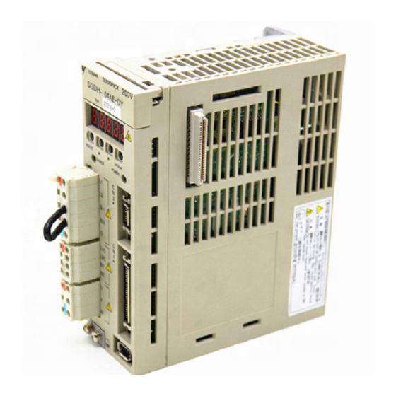
1 Checking Products and Part Names Product Part Names The following diagram illustrates the product part names of the NS115. Ground wire: Connect to the terminal marked "G" on the SGDH SERVOPACK. Rotary Switch (SW1): Used to set the MECHATROLINK-II station address. NS115 LED A: Lit when an alarm occurs. LED R: Lit when MECHATROLINK-II communications are in progress. DIP Switch (SW2): Used to set MECHATROLINK-II communications. Nameplate: Indicates the model and serial numbers. MECHATROLINK-II Communications CN6A and CN6B Connectors: Connects to the MECHATROLINK-II system. CN4 Fully Closed Encoder Signal Connector: Used for fully closed signal connection. Fig. 1.3 NS115... -
Page 19: Mounting The Ns115
By mounting an NS115, the SGDH SERVOPACK can be used in a MECHATROLINK-II sys- tem. Use the following procedure to ensure NS115 is mounted correctly. 1. Remove the connector cover from the CN10 connector on the SERVOPACK. CN10 YASKAWA SERVOPACK SGDH Connector cover... - Page 20 1 Checking Products and Part Names 2. Mount the NS115 on the SERVOPACK. Connector (Connect to SERVOPACK) SERVOPACK connector CN10 SERVOPACK YASKAWA SGDH- 3. For grounding, connect a ground wire of the NS115 to the point marked “G” on the SERVOPACK. Ground wire "G" YASKAWA SERVOPACK...
- Page 21 1.3 Mounting the NS115 When the NS115 has been mounted correctly, the SERVOPACK will appear as shown in the following diagram. YASKAWA SERVOPACK SGDH 200V NS115...
-
Page 22: Installation
Installation This chapter describes precautions for Σ-ΙΙ Series product installation. The SGDH SERVOPACKs are base-mounted servo controller. Incorrect instal- lation will cause problems. Always observe the installation precautions shown in this chapter. 2.1 Storage Conditions - - - - - - - - - - - - - - - - - - - - - - - - - - - - - - 2-2 2.2 Installation Site - - - - - - - - - - - - - - - - - - - - - - - - - - - - - - - - 2-2 2.3 Orientation - - - - - - - - - - - - - - - - - - - - - - - - - - - - - - - - - - - - 2-3 2.4 Installation - - - - - - - - - - - - - - - - - - - - - - - - - - - - - - - - - - - - 2-4... -
Page 23: Storage Conditions
2 Installation Storage Conditions Store the SERVOPACK within the following temperature range when it is stored with the power cable disconnected. -20 to 85°C YASKAWA SERVOPACK SGDH 200V NS115 Σ-II Series SGDH SERVOPACK with NS115 mounted Installation Site Take the following precautions at the installation site. -
Page 24: Orientation
2.3 Orientation Orientation Install the SERVOPACK perpendicular to the wall as shown in the figure. The SERVOPACK must be oriented this way because it is designed to be cooled by natural convection or cooling fan. Secure the SERVOPACK using 2 to 4 mounting holes. The number of holes depends on the SERVOPACK capacity. -
Page 25: Installation
2 Installation Installation Follow the procedure below to install multiple SERVOPACKs side by side in a control panel. Cooling fan Cooling fan 50 mm (1.97in) min. 50 mm (1.97in) min. 10 mm (0.39in) min. 30 mm (1.18in) min. SERVOPACK Orientation Install the SERVOPACK perpendicular to the wall so that the front panel (containing con- nectors) faces outward. -
Page 26: Wiring
Wiring This chapter describes the procedure used to connect Σ-ΙΙ Series products to peripheral devices when an NS115 is mounted and gives typical examples of I/ O signal connections. 3.1 Connecting to Peripheral Devices - - - - - - - - - - - - - - - - - - - 3-2 3.1.1 Single-phase (100 V or 200 V) Main Circuit Specifications - - - - - - - - 3-3 3.1.2 Three-phase (200 V) Main Circuit Specifications - - - - - - - - - - - - - - - 3-4 3.2 SERVOPACK Internal Block Diagrams - - - - - - - - - - - - - - - - 3-5... -
Page 27: Connecting To Peripheral Devices
3 Wiring Connecting to Peripheral Devices This section provides examples of standard Σ-ΙΙ Series product connections to peripheral devices. It also briefly explains how to connect each peripheral device. -
Page 28: Single-Phase (100 V Or 200 V) Main Circuit Specifications
3.1.1 Single-phase (100 V or 200 V) Main Circuit Specifications Host Controller for MECHATROLINK-II Controller Molded-case Circuit Power supply Breaker (MCCB) Single-phase 200 VAC MP2300 218IF-01 YASKAWA R S T STRX STOP Protects the pow- INIT TEST CNFG TEST PORT... -
Page 29: Three-Phase (200 V) Main Circuit Specifications
Three-phase (200 V) Main Circuit Specifications Controller for MECHATROLINK-II Host Power supply Molded-case Circuit Single-phase 200 VAC Controller Breaker (MCCB) R S T 218IF-01 MP2300 Protects the pow- YASKAWA STRX er line by shutting STOP INIT TEST CNFG TEST the circuit OFF PORT OFF ON M-I/II... -
Page 30: Servopack Internal Block Diagrams
3.2 SERVOPACK Internal Block Diagrams SERVOPACK Internal Block Diagrams The following sections show an internal block diagram for the SERVOPACK with an NS115. 30 to 400 W 200-V and 30 to 200 W 100-V Models Single-phase +10% 200 to 230 V B1 B2 -15% (50/60Hz) -
Page 31: I/O Signals
3 Wiring 3.3.1 Connection Example of I/O Signal Connector (CN1) I/O Signals This section describes I/O signals for the SERVOPACK with NS115. 3.3.1 Connection Example of I/O Signal Connector (CN1) The following diagram shows a typical example of I/O signal connections. SGDH SERVOPACK BAT + ALO1... -
Page 32: I/O Signals Connector (Cn1)
3.3 I/O Signals 3.3.2 I/O Signals Connector (CN1) The following diagram shows the layout of CN1 terminals. CN1 Terminal Layout /COIN- Positioning complete /BK+ * Brake inter- output lock output /BK- * Brake inter- lock output Servo ready RDY+ output /S-RDY- Servo ready output... -
Page 33: I/O Signal Names And Functions
3 Wiring 3.3.3 I/O Signal Names and Functions 3.3.3 I/O Signal Names and Functions The following section describes SERVOPACK I/O signal names and functions. Input Signals Signal Name Pin No. Function Common /DEC Zero point return deceleration limit switch: Deceleration LS used when the motor returns to the zero point. -
Page 34: Interface Circuits
3.3 I/O Signals 3.3.4 Interface Circuits This section shows examples of SERVOPACK I/O signal connection to the host controller. Sequence Input Circuit Interface The sequence input circuit interface connects through a relay or open-collector transistor cir- cuit. Select a low-current relay, otherwise a faulty contact will result. SERVOPACK SERVOPACK 24 VDC... - Page 35 3 Wiring 3.3.4 Interface Circuits Photocoupler output circuits are used for servo alarm, servo ready, and other sequence output signal circuits. Connect a photocoupler output circuit through a relay or line receiver circuit. 5 to 24 VDC Relay 5 to 12 VDC SERVOPACK ...
-
Page 36: Fully Closed Encoder Signals Connector (Cn4)
3.4 Fully Closed Encoder Signals Connector (CN4) Fully Closed Encoder Signals Connector (CN4) This section describes the wiring for the fully closed encoder signals connector (CN4). 3.4.1 Fully Closed Encoder Connection Example The following diagram shows an example of CN4 connections. NS115 PG0V 1,2,3... - Page 37 3 Wiring 3.4.2 CN4 Connector Terminal Layout CN4 Specifications Specifications for Applicable Receptacles SERVOPACK Soldered Case Manufacturer Connectors 10220-52A2JL 10120-3000VE 10320-52A0-008 SUMITOMO 3M 20-pin Right Angle Plug LTD. 3-12...
-
Page 38: Connections For Mechatrolink-Ii Communications
3.5.1 MECHATROLINK-II Communications Connection Example The following diagram shows an example of connections between a host controller and a SERVOPACK using MECHATROLINK-II communications cables (CN6A, CN6B). Host controller 218IF-01 MP2300 YASKAWA STRX STOP INIT TEST CNFG TEST PORT OFF ON... -
Page 39: Mechatrolink-Ii Communications Connectors (Cn6A, Cn6B)
3 Wiring 3.5.2 MECHATROLINK-II Communications Connectors (CN6A, CN6B) 3.5.2 MECHATROLINK-II Communications Connectors (CN6A, CN6B) The terminal layout and specifications of the CN6A and CN6B connectors are shown below. CN6A and CN6B Connectors Terminal Layout Not connected Serial data I/O Not connected Note: The connector shell is connected to the FG (frame ground). - Page 40 3.5 Connections for MECHATROLINK-II Communications Cables Be sure to use the specified cables. For more information on cables, refer to 10.2 MECHATROLINK/MECHATROLINK-II Communications Cables and Terminator. Cable Length The total cable length must be 50 m or less. Cable Length for Stations The length of the cable between stations must be 0.5 m or more.
-
Page 41: Examples Of Combined Connections (For Fully Closed Encoders)
3 Wiring 3.6.1 Single-phase Power Supply Specifications Examples of Combined Connections (for Fully Closed Encoders) The following diagrams show examples of combined connections. 3.6.1 Single-phase Power Supply Specifications +10% Single-phase 200 to 230 VAC -15% (50/60Hz) Power Power Alarm Noise filter processing Be sure to attach a surge suppressor to the excitation coil of the magnetic contactor and relay. - Page 42 3.6 Examples of Combined Connections (for Fully Closed Encoders) * 1. represents twisted-pair wires. * 2. When using an absolute encoder, connect a backup battery only when there is no battery con- nected to the CN8. * 3. Make signal allocations using parameters.(Refer to 6.1.2 Standard Settings for CN1 I/O Sig- nals.) * 4.
-
Page 43: Three-Phase Power Supply Specifications
3 Wiring 3.6.2 Three-phase Power Supply Specifications 3.6.2 Three-phase Power Supply Specifications +10% Three-phase 200 to 230 VAC -15% 50/60Hz Power Power Alarm Noise filter processing Be sure to attach a surge suppressor to the excitation coil of the magnetic contactor and relay. Servomotor SGDH- E SERVOPACK *3... - Page 44 3.6 Examples of Combined Connections (for Fully Closed Encoders) * 1. represents twisted-pair wires. * 2. When using an absolute encoder, connect a backup battery only when there is no battery con- nected to the CN8. * 3. Connect an external regenerative resistor between terminals B1 and B2 for SERVOPACKs with a capacity of 6.0 kW or higher.
-
Page 45: Mechatrolink-Ii Communications
MECHATROLINK-II Communications This chapter describes MECHATROLINK-II communications specifications, commands, and power ON sequence. 4.1 Specifications and Configuration - - - - - - - - - - - - - - - - - - - - 4-3 4.1.1 Specifications - - - - - - - - - - - - - - - - - - - - - - - - - - - - - - - - - - - - - - - - 4-3 4.1.2 System Configuration - - - - - - - - - - - - - - - - - - - - - - - - - - - - - - - - - - 4-3 4.2 Switches for MECHATROLINK-II Communications Settings - 4-4 4.2.1 Communications Settings - - - - - - - - - - - - - - - - - - - - - - - - - - - - - - - 4-4... - Page 46 4 MECHATROLINK-II Communications 4.3.22 Servo ON (SV_ON: 31H) - - - - - - - - - - - - - - - - - - - - - - - - - - - - - - 4-29 4.3.23 Servo OFF (SV_OFF: 32H) - - - - - - - - - - - - - - - - - - - - - - - - - - - - 4-30 4.3.24 Interpolation Feed (INTERPOLATE: 34H) - - - - - - - - - - - - - - - - - - 4-31 4.3.25 Positioning (POSING: 35H) - - - - - - - - - - - - - - - - - - - - - - - - - - - - 4-32 4.3.26 Constant Speed Feed (FEED: 36H) - - - - - - - - - - - - - - - - - - - - - - 4-33...
-
Page 47: Specifications And Configuration
4.1 Specifications and Configuration Specifications and Configuration 4.1.1 Specifications Items that are not described in this chapter are based on the MECHATROLINK application layer. For more details, refer to the following manuals. • MECHATROLINK System User’s Manual (SIE-S800-26.1) • MECHATROLINK Servo Command User’s Manual (SIE-S800-26.2) 4.1.2 System Configuration The following illustration shows system configuration. -
Page 48: Switches For Mechatrolink-Ii Communications Settings
4 MECHATROLINK-II Communications 4.2.1 Communications Settings Switches for MECHATROLINK-II Communications Settings This section describes the switch settings necessary for MECHATROLINK-II communications. 4.2.1 Communications Settings The SW2 DIP switch sets the MECHATROLINK-II communications settings, as shown below. Settings that have been changed are enabled when the power is turned OFF and SW2 (factory setting) 7 8 9 Item... -
Page 49: Setting The Transmission Cycle
4.2 Switches for MECHATROLINK-II Communications Settings 4.2.2 Setting the Transmission Cycle The transmission cycle and number of stations that can be set with the NS115 are shown below. ì Table 4.1 Number of Connectable Stations Determined by Transmission Cycle and Transmission Bytes Transmission Transmission Cycle Bytes... -
Page 50: Setting The Station Address
4 MECHATROLINK-II Communications 4.2.3 Setting the Station Address 4.2.3 Setting the Station Address The station address is set as shown in Table 4.2, using the rotary switch (SW1) and piano switch (SW2 bit 3). Settings that have been changed are enabled when the power is turned OFF and ON. -
Page 51: Main Commands
4.3 Main Commands Main Commands The following sections describe main command specific items that are unique to the NS115. The MECHATROLINK-II main commands are upwardly compatible with the MECHATROLINK commands. They use the first to the sixteenth bytes of the command and response data. -
Page 52: No Operation (Nop: 00H)
4 MECHATROLINK-II Communications 4.3.1 No Operation (NOP: 00H) 4.3.1 No Operation (NOP: 00H) Byte Description Command Response Processing Network com- Synchronization Asynchronous classifications classifications mand group ALARM Processing time Within transmis- Subcommand Can be used. sion cycle STATUS • Returns the status of the ALM, WARNG, and CMDRDY in STATUS bytes only. -
Page 53: Read Parameter (Prm_Rd: 01H)
4.3 Main Commands 4.3.2 Read Parameter (PRM_RD: 01H) Byte PRM_RD Description Command Response Processing Data communica- Synchronization Asynchronous classifications tions command classifications group ALARM Processing time Subcommand Refer to the fol- Cannot be used. lowing description STATUS • Reads current operating parameters. The latest setting value, however, is read for offline parameters. -
Page 54: Write Parameter (Prm_Wr: 02H)
4 MECHATROLINK-II Communications 4.3.3 Write Parameter (PRM_WR: 02H) 4.3.3 Write Parameter (PRM_WR: 02H) Byte PRM_WR Description Command Response Processing Data communica- Synchronization Asynchronous classifications classifications tions command group ALARM Processing time Subcommand Refer to the fol- Cannot be used. lowing description STATUS •... -
Page 55: Read Id (Id_Rd: 03H)
4.3 Main Commands 4.3.4 Read ID (ID_RD: 03H) Byte ID_RD Description Command Response Processing Data communica- Synchronization Asynchronous classifications classifications tions command group ALARM Processing time Within 1 sec Subcommand Cannot be used. STATUS • Reads the ID. The corresponding DEVICE_COD is shown in the table on the following page. -
Page 56: Set Up Device (Config: 04H)
4 MECHATROLINK-II Communications 4.3.5 Set Up Device (CONFIG: 04H) 4.3.5 Set Up Device (CONFIG: 04H) Byte CONFIG Description Command Response Processing Control com- Synchronization Asynchronous classifications classifications mand group ALARM Processing time ∗ Subcommand Cannot be used. Within 4 s + α STATUS •... -
Page 57: Read Alarm Or Warning (Alm_Rd: 05H)
4.3 Main Commands 4.3.6 Read Alarm or Warning (ALM_RD: 05H) Byte ALM_RD Description Command Response Processing clas- Control com- Synchronization Asynchronous sifications mand group classifications ALARM Processing time Refer to Subcommand Cannot be used Details of ALM_RD_MOD. STATUS • Reads the following alarm or warning status. - Current alarm/warning status - Alarm status history* (warning history is not preserved.) ALM_RD_MOD ALM_RD_MOD... -
Page 58: Clear Alarm/Warning (Alm_Clr: 06H)
4 MECHATROLINK-II Communications 4.3.7 Clear Alarm/Warning (ALM_CLR: 06H) 4.3.7 Clear Alarm/Warning (ALM_CLR: 06H) Byte ALM_CLR Description Command Response Processing Control command Synchronization Asynchronous classifications classifications group ALARM Processing time Refer to Subcommand Cannot be used. Details of ALM_CLR_MOD. STATUS • Clears the following alarm or warning status. - Current alarm/warning status - Alarm status history * (warning history is not preserved.) ALM_CLR_MOD ALM_CLR_MOD... -
Page 59: Start Synchronous Communications (Sync_Set: 0Dh)
4.3 Main Commands 4.3.8 Start Synchronous Communications (SYNC_SET: 0DH) Byte SYNC_SET Description Command Response Processing Network com- Synchronization Asynchronous classifications mand group classifications ALARM Processing time Transmission Subcommand Cannot be used. cycle or more STATUS • Starts synchronous communications. Switches from phase 2 to phase 3. •... -
Page 60: Mechatrolink-Ii Connection (Connect: 0Eh)
4 MECHATROLINK-II Communications 4.3.9 MECHATROLINK-II Connection (CONNECT: 0EH) 4.3.9 MECHATROLINK-II Connection (CONNECT: 0EH) Byte CONNECT Description Byte Description Command Response Processing Network com- Synchronization Asynchronous classifications classifications mand group ALARM Processing time Communications Subcommand Cannot be used. cycle or more STATUS •... -
Page 61: Disconnection (Disconnect: 0Fh)
4.3 Main Commands 4.3.10 Disconnection (DISCONNECT: 0FH) Byte DISCONNECT Description Command Response Processing Network com- Synchronization Asynchronous classifications mand group classifications ALARM Processing time Communications Subcommand Cannot be used. cycle or more STATUS • Releases the MECHATROLINK-II connection. The SERVOPACK changes communication to phase 1. -
Page 62: Read Non-Volatile Parameter (Pprm_Rd: 1Bh)
4 MECHATROLINK-II Communications 4.3.11 Read Non-volatile Parameter (PPRM_RD: 1BH) 4.3.11 Read Non-volatile Parameter (PPRM_RD: 1BH) Byte PPRM_RD Description Command Response Processing Data communica- Synchronization Asynchronous classifications classifications tions command group ALARM Processing time Subcommand Within communi- Cannot be used. cations cycle STATUS •... -
Page 63: Write Non-Volatile Parameter (Pprm_Wr: 1Ch)
4.3 Main Commands 4.3.12 Write Non-volatile Parameter (PPRM_WR: 1CH) Byte PPRM_WR Description Command Response Processing Data communica- Synchronization Asynchronous classifications tions command classifications group ALARM Processing time Subcommand Within 200 ms Cannot be used. STATUS • Saves parameters in E PROM. -
Page 64: Set Coordinates (Pos_Set: 20H)
4 MECHATROLINK-II Communications 4.3.13 Set Coordinates (POS_SET: 20H) 4.3.13 Set Coordinates (POS_SET: 20H) Byte POS_SET Description Command Response Processing Data communica- Synchronization Asynchronous classifications classifications tions command group ALARM Processing time Subcommand Within 200 ms Cannot be used. STATUS • Sets coordinates. REFE can also enable zero point (ZPOINT) and software limits. -
Page 65: Apply Brake (Brk_On: 21H)
4.3 Main Commands 4.3.14 Apply Brake (BRK_ON: 21H) Byte BRK_ON Description Command Response Processing Control com- Synchronization Asynchronous classifications mand group classifications ALARM Processing time Within communi- Subcommand Cannot be used. cations cycle STATUS • Applies brake. This command is enabled when Pn005.0 is set to 1. •... -
Page 66: Release Brake (Brk_Off: 22H)
4 MECHATROLINK-II Communications 4.3.15 Release Brake (BRK_OFF: 22H) 4.3.15 Release Brake (BRK_OFF: 22H) Byte BRK_OFF Description Command Response Processing Control com- Synchronization Asynchronous classifications classifications mand group ALARM Processing time Within communi- Subcommand Cannot be used. cations cycle STATUS • Applies brake. This command is enabled when Pn005.0 is set to 1. •... -
Page 67: Turn Sensor On (Sens_On: 23H)
4.3 Main Commands 4.3.16 Turn Sensor ON (SENS_ON: 23H): Byte SENS_ON Description Command Response Processing Control com- Synchronization Asynchronous classifications mand group classifications ALARM Processing time Within 2 sec Subcommand Cannot be used. STATUS • Obtains the initial position data when an absolute encoder is used. •... -
Page 68: Turn Sensor Off (Sens_Off: 24H)
4 MECHATROLINK-II Communications 4.3.17 Turn Sensor OFF (SENS_OFF: 24H) 4.3.17 Turn Sensor OFF (SENS_OFF: 24H) Byte SENS_OFF Description Command Response Processing Control com- Synchronization Asynchronous classifications classifications mand group ALARM Processing time Within 500 ms Subcommand Cannot be used. STATUS •... -
Page 69: Stop Motion (Hold: 25H)
4.3 Main Commands 4.3.18 Stop Motion (HOLD: 25H) Byte HOLD Description Command Response Processing Motion command Synchronization Asynchronous classifications group classifications ALARM Processing time Within communi- Subcommand Can be used. cations cycle OPTION STATUS • From current motion status, performs a deceleration stop and positioning according to the deceleration value set in the parameters. -
Page 70: Request Latch Mode (Ltmod_On: 28H)
4 MECHATROLINK-II Communications 4.3.19 Request Latch Mode (LTMOD_ON: 28H) 4.3.19 Request Latch Mode (LTMOD_ON: 28H) Byte LTMOD_ON Description Command Response Processing Control com- Synchronization Asynchronous classifications classifications mand group LT_SGN ALARM Processing time Within communi- Subcommand Can be used. cations cycle STATUS •... -
Page 71: Release Latch Mode (Ltmod_Off: 29H)
4.3 Main Commands 4.3.20 Release Latch Mode (LTMOD_OFF: 29H) Byte LTMOD_OFF Description Command Response Processing Control com- Synchronization Asynchronous classifications mand group classifications ALARM Processing time Within communi- Subcommand Can be used. cations cycle STATUS • Releases the modal latch mode. •... -
Page 72: Status Monitoring (Smon: 30H)
4 MECHATROLINK-II Communications 4.3.21 Status Monitoring (SMON: 30H) 4.3.21 Status Monitoring (SMON: 30H) Byte SMON Description Command Response Processing Control com- Synchronization Asynchronous classifications classifications mand group ALARM Processing time Within communi- Subcommand Can be used. cations cycle STATUS • Reads the current status of the Servo. •... -
Page 73: Servo On (Sv_On: 31H)
4.3 Main Commands 4.3.22 Servo ON (SV_ON: 31H) Byte SV_ON Description Command Response Processing Control com- Synchronization Asynchronous classifications mand group classifications ALARM Processing time Within 50 ms nor- Subcommand Can be used. mally OPTION STATUS • The SERVOPACK changes to Servo ON. •... -
Page 74: Servo Off (Sv_Off: 32H)
4 MECHATROLINK-II Communications 4.3.23 Servo OFF (SV_OFF: 32H) 4.3.23 Servo OFF (SV_OFF: 32H) Byte SV_OFF Description Command Response Processing Control com- Synchronization Asynchronous classifications classifications mand group ALARM Processing time Follow settings Subcommand Can be used. from Pn506 to Pn508. STATUS •... -
Page 75: Interpolation Feed (Interpolate: 34H)
4.3 Main Commands 4.3.24 Interpolation Feed (INTERPOLATE: 34H) Byte INTERPOLATE Description Command Response Processing Motion command Synchronization Synchronous classifications group classifications ALARM Processing time Within communi- Subcommand Can be used. cations cycle OPTION STATUS • Starts interpolation feeding. Speed feed forward (VFF) can be specified simul- taneously. -
Page 76: Positioning (Posing: 35H)
4 MECHATROLINK-II Communications 4.3.25 Positioning (POSING: 35H) 4.3.25 Positioning (POSING: 35H) Byte POSING Description Command Response Processing Motion command Synchronization Synchronous classifications classifications group ALARM Processing time Within communi- Subcommand Can be used. cations cycle OPTION STATUS • Performs positioning at the target position (TPOS) using the target speed (TSPD). -
Page 77: Constant Speed Feed (Feed: 36H)
4.3 Main Commands 4.3.26 Constant Speed Feed (FEED: 36H) Byte FEED Description Command Response Processing Motion command Synchronization Asynchronous classifications group classifications ALARM Processing time Within communi- Subcommand Can be used. cations cycle OPTION STATUS • Performs constant speed feeding using the target speed (TSPD). Use the Stop Motion command (HOLD: 25H) to stop the constant speed feeding. - Page 78 4 MECHATROLINK-II Communications 4.3.26 Constant Speed Feed (FEED: 36H) Related Parameters Pn No. Description Pn80A First-step Linear Acceleration Parameter Pn80B Second-step Linear Acceleration Parameter Pn80C Acceleration Parameter Switching Speed Pn80D First-step Linear Deceleration Parameter Pn80E Second-step Linear Deceleration Parameter Pn80F Deceleration Parameter Switching Speed 4-34...
-
Page 79: Interpolation Feeding With Position Detection (Latch: 38H)
4.3 Main Commands 4.3.27 Interpolation Feeding with Position Detection (LATCH: 38H) Byte LATCH Description Command Response Processing Motion command Synchronization Synchronous classifications group classifications LT_SGN ALARM Processing time Within communi- Subcommand Can be used. cations cycle OPTION STATUS • Performs interpolation feeding and latches the position using the latch signal simultaneously. - Page 80 4 MECHATROLINK-II Communications 4.3.27 Interpolation Feeding with Position Detection (LATCH: 38H) Related Parameters Pn No. Description Pn511 Input Signal Selections 5 Pn820 Latching Area Upper Limit Pn822 Latching Area Lower Limit 4-36...
-
Page 81: External Input Positioning (Ex_Posing: 39H)
4.3 Main Commands 4.3.28 External Input Positioning (EX_POSING: 39H) Byte EX_POSING Description Command Response Processing Motion command Synchronization Asynchronous classifications group classifications LT_SGN ALARM Processing time Within communi- Subcommand Can be used. cations cycle OPTION STATUS • Moves toward the target position (TPOS) at the target speed (TSPD). When a latch signal is input midway, positioning is performed according to the final travel distance for external position specified in the parameter. - Page 82 4 MECHATROLINK-II Communications 4.3.28 External Input Positioning (EX_POSING: 39H) Related Parameters Pn No. Description Pn No. Description Pn511 Input Signal Selections 5 Pn820 Latching Area Upper Limit Pn80A First-step Linear Acceleration Parameter Pn822 Latching Area Lower Limit Pn80B Second-step Linear Acceleration Parameter Pn80C Acceleration Parameter Switching Speed Pn80D...
-
Page 83: Zero Point Return (Zret: 3Ah)
4.3 Main Commands 4.3.29 Zero Point Return (ZRET: 3AH) Byte ZRET Description Command Response Processing Motion command Synchronization Asynchronous classifications group classifications LT_SGN ALARM Processing time Within communi- Subcommand Can be used. cations cycle OPTION STATUS • Accelerates to the target speed (TSPD) in the direction specified in the param- eter (Pn816) and continues to move at the target speed. - Page 84 4 MECHATROLINK-II Communications 4.3.29 Zero Point Return (ZRET: 3AH) Related Parameters Pn No. Description Pn No. Description Pn511 Input Signal Selections 5 Pn820 Latching Area Upper Limit Pn80A First-step Linear Acceleration Parameter Pn822 Latching Area Lower Limit Pn80B Second-step Linear Acceleration Parameter Pn80C Acceleration Parameter Switching Speed Pn80D...
-
Page 85: Velocity Control (Velctrl: 3Ch)
4.3 Main Commands 4.3.30 Velocity Control (VELCTRL: 3CH) Byte VECTRL Description Command Response Processing Motion command Synchronization Asynchronous classifications group classifications ALARM Processing time Within communi- Subcommand Can be used. cations cycle OPTION STATUS • Controls speed. (The Servo does not perform position control, but directly controls the speed of the speed loop.) Soft-start acceleration/deceleration can also be used by setting the parameters. - Page 86 4 MECHATROLINK-II Communications 4.3.30 Velocity Control (VELCTRL: 3CH) Torque Reference Option Operation Pn No. and Torque Reference Option Operation Digit Place Value Pn002.0 The torque reference option is not effective. Set P_TLIM (TFF), N_TLIM to 0. P_TLIM operates as the torque limit value. Set N_TLIM to 0.
-
Page 87: Torque Control (Trqctrl: 3Dh)
4.3 Main Commands 4.3.31 Torque Control (TRQCTRL: 3DH) Byte TRQCTRL Description Command Response Processing Motion command Synchronization Asynchronous classifications group classifications ALARM Processing time Within communi- Subcommand Can be used. cations cycle OPTION STATUS • The Servo does not perform position control and speed control, but directly performs torque control. - Page 88 4 MECHATROLINK-II Communications 4.3.31 Torque Control (TRQCTRL: 3DH) Speed Reference Option Operation Pn No. and Speed Reference Option Operation Digit Place Value Pn002.1 The speed reference option is not effective. Set VLIM to 0. VLIM operates as the speed limit value. 4-44...
-
Page 89: Adjusting (Adj: 3Eh)
4.3 Main Commands 4.3.32 Adjusting (ADJ: 3EH) Byte Description Command Response Processing Data communica- Synchronization Asynchronous classifications tions command classifications group ALARM Processing time Subcommand Depends on pro- Cannot be used. cessing. STATUS • This command is for maintenance. • Refer to Appendix C Using the Adjusting Command (ADJ: 3EH). •... -
Page 90: General-Purpose Servo Control (Svctrl: 3Fh)
4 MECHATROLINK-II Communications 4.3.33 General-purpose Servo Control (SVCTRL: 3FH) 4.3.33 General-purpose Servo Control (SVCTRL: 3FH) Byte SVCTRL Description Command Response Processing Compound com- Synchronization Synchronous, classifications classifications mand group asynchronous SUBCTRL ALARM Processing time Depends on pro- Subcommand Can be used. cessing. - Page 91 4.3 Main Commands Sub-control: SUBCTRL RESERVE MOTION RESERVE SET_L L_SGN Select motion Latch Select latch signal command Select Latch Signal: L_SGN Latch Signal Phase C EXT1 EXT2 EXT3 Select Motion: MOTION Motion • During phase 1, a parameter setting warning (A.94) will occur for POSING HOLD and FEED, and the commands will be ignored.
-
Page 92: Mechatrolink Connection (Connect: 0Eh)
4 MECHATROLINK-II Communications 4.3.34 MECHATROLINK Connection (CONNECT: 0EH) 4.3.34 MECHATROLINK Connection (CONNECT: 0EH) Byte CONNECT Description Command Response Processing Network com- Synchronization Asynchronous classifications classifications mand group ALARM Processing time Communications Subcommand Cannot be used. cycle or more STATUS • Establishes a MECHATROLINK connection. Sets the communications mode according to COM_MODE. -
Page 93: Subcommands
4.4 Subcommands Subcommands This section describes the subcommands for the NS115. The MECHATROLINK-II subcommands can be used by specifying them with the CONNECT command when the MECHATROLINK-II communications is started. They use the seventeenth to the twenty-ninth bytes of the command and response data. (They cannot be used with MECHATROLINK-I.) The subcommands can be used in combination with the main commands described in Table 4.3. -
Page 94: No Operation (Nop: 00H)
4 MECHATROLINK-II Communications 4.4.1 No Operation (NOP: 00H) Table 4.3 Combination of Main Commands and Subcommands (cont’d) Code Main Subcommand Command PRM_RD PRM_WR ALM_RD PPRM_WR LTMOD_ON LTMOD_OFF SMON SVCTRL Note: OK: This combination can be used. NO: This combination cannot be used. 4.4.1 No Operation (NOP: 00H) Byte... -
Page 95: Read Parameter (Prm_Rd:01H)
4.4 Subcommands 4.4.2 Read Parameter (PRM_RD:01H) Byte PRM_RD Description Command Response Processing Data communica- Processing time Within 6 ms classifications tions command group Reads the parameters. This command has the same function as the main command PRM_RD. Substatus SIZE SIZE PARAMETER 4.4.3 Write Parameter (PRM_WR:02H) -
Page 96: Read Alarm Or Warning (Alm_Rd:05H)
4 MECHATROLINK-II Communications 4.4.4 Read Alarm or Warning (ALM_RD:05H) 4.4.4 Read Alarm or Warning (ALM_RD:05H) Byte ALM_RD Description Command Response Processing clas- Processing time Data communica- 6 ms to 2 s sifications tions command group Reads the alarm or warning. This command has the same function as the main com- mand ALM_RD. -
Page 97: Request Latch Mode (Ltmod_On:28H)
4.4 Subcommands 4.4.6 Request Latch Mode (LTMOD_ON:28H) Byte LTMOD_ON Description Command Response Processing Control command Processing time Within communi- classifications group cations cycle Sets the modal latch mode. This command has the same function as the main com- mand LTMOD_ON. LT_SGN Substatus SEL_MON3/4... -
Page 98: Status Monitoring (Smon:30H)
4 MECHATROLINK-II Communications 4.4.8 Status Monitoring (SMON:30H) 4.4.8 Status Monitoring (SMON:30H) Byte SMON Description Command Response Processing Processing time Data communica- Within communi- classifications tions command cations cycle group Reads the monitoring information specified in SEL_MON3/4. This command has the same function as the main command SMON. Substatus SEL_MON3/4 SEL_MON3/4... -
Page 99: Command Data Field
4.5 Command Data Field Command Data Field This section describes command data in main commands and subcommands. 4.5.1 Latch Signal Field Specifications: LT_SGN The latch signal field specifications (LT_SGN) can be designated using the following com- mands: LATCH, EX_POSING, ZRET, LTMOD_ON The latch signal field is used to select latch signals for position data, with the second byte of the above main commands, or the eighteenth byte reserved area of the subcommands. -
Page 100: Option Field Specifications: Option
4 MECHATROLINK-II Communications 4.5.2 Option Field Specifications: OPTION 4.5.2 Option Field Specifications: OPTION The option field specifications (OPTION) can be designated using the following main com- mands: SV_ON, HOLD, INTERPOLATE, POSING, LATCH, EX_POSING, ZRET, FEED, VELCTRL, TRQCTRL, SVCTRL The option field is used to add motion command functions for individual products, with the third to fourth byte reserved area of the above main commands. -
Page 101: Status Field Specifications: Status
4.5 Command Data Field 4.5.3 Status Field Specifications: STATUS The status field is used to monitor the Servo status with the third to fourth byte reserved area of the main commands. Refer to the following table for details on bit allocation. Status Field PSET/ ZPOINT... -
Page 102: Monitor Selection And Monitor Information Field Specifications
4 MECHATROLINK-II Communications 4.5.4 Monitor Selection and Monitor Information Field Specifications: SEL_MON1/2/3/4, MONITOR1/2/3/4 (cont’d) Name Description Details Control Value Mode T_LIM Torque limit Not during torque limit During torque limit L_CMP Latch completion Latch not completed Latch completed NEAR Positioning proximity Out of positioning proxim- Position ity range... -
Page 103: Io Monitor Field Specifications: Io_Mon
4.5 Command Data Field MONITOR1/2/3/4 Monitor Codes Monitor Name Description Unit Codes* Reference position in the reference coordinate sys- Reference units tem (position after reference filter procedure) MPOS Reference position in the mechanical coordinate Reference units system PERR Position error Reference units APOS Feedback position in the mechanical coordinate... - Page 104 4 MECHATROLINK-II Communications 4.5.5 IO Monitor Field Specifications: IO_MON IO Monitor Field EXT2 EXT1 N_OT P_OT − − IO15 IO14 IO13 IO12 EXT3 Name Description Settings Value P_OT Forward run prohibited input N_OT Reverse run prohibited input Zero point return deceleration LS input Encoder phase A input Encoder phase B input Encoder phase C input...
-
Page 105: Substatus Field Specifications: Substatus
4.5 Command Data Field 4.5.6 Substatus Field Specifications: SUBSTATUS The substatus field is used to monitor the subcommand status with the eighteenth byte reserved area of the subcommands. SUBSTATUS − − − − − SBCMDRDY SBWARNG SBALM Name Description Details Value SBALM Subcommand alarm occurrence... -
Page 106: Command And Response Timing
4 MECHATROLINK-II Communications 4.6.1 Command Data Execution Timing Command and Response Timing This section describes the execution timing for command data and the input timing for monitor data. This timing is fixed, regardless of the transmission cycle and communications cycle. 4.6.1 Command Data Execution Timing Motion commands (POSING, INTERPOLATE) and the OPTION command are executed... -
Page 107: Operation Sequence
4.7 Operation Sequence Operation Sequence This section describes outline of the operation sequence. Refer to 4.3 Main Commands and 4.4 Subcommands for details of command functions and settings. 4.7.1 Operation Sequence for Managing Parameters Using a Controller The following describes the operation sequence for managing parameters using a controller. The controller manages the necessary parameters, and transfers them when the power is turned ON. -
Page 108: Operation Sequence For Managing Parameters Using Servopack
4 MECHATROLINK-II Communications 4.7.2 Operation Sequence for Managing Parameters Using SERVOPACK 4.7.2 Operation Sequence for Managing Parameters Using SERVOPACK The following describes the operation sequence for managing parameters using the non-vol- atile memory of the SERVOPACK. As described below, divide the operation into two steps. Step 1: Saving parameters (during set-up) Step 2: Ordinary operation sequence Table 4.5 Step 1: Saving Parameters (During Set-up) -
Page 109: Operation Sequence When Being Servo On
4.7 Operation Sequence Table 4.6 Step 2: Ordinary Operation Sequence Proce- Item Command Description Phase dure Turn ON control and main cir- NOP/DISONNECT* Turn ON power supplies. cuit power supplies. 2 or 3 Establish connection. CONNECT Establish communications. Start the WDT count. 2 or 3 Check information such as ID_RD... -
Page 110: Operation Sequence When Ot (Overtravel Limit Switch) Signal Is Input
4 MECHATROLINK-II Communications 4.7.4 Operation Sequence When OT (Overtravel Limit Switch) Signal Is Input 4.7.4 Operation Sequence When OT (Overtravel Limit Switch) Signal Is Input When the OT signal is input, the SERVOPACK prohibits rotation in the OT signal direction. This is performed as specified in parameter Pn001, and the SERVOPACK continues to con- trol the motor while this rotation is prohibited. -
Page 111: Trial Operation
Trial Operation This chapter describes the procedure for trial operation of the NS115. 5.1 Check Items before Trial Operation - - - - - - - - - - - - - - - - - - 5-2 5.1.1 Servomotors - - - - - - - - - - - - - - - - - - - - - - - - - - - - - - - - - - - - - - - - - 5-2 5.1.2 SERVOPACKs - - - - - - - - - - - - - - - - - - - - - - - - - - - - - - - - - - - - - - - 5-2 5.2 Trial Operation for MECHATROLINK-II Communications - - - 5-3 5.2.1 Preparations for Trial Operation - - - - - - - - - - - - - - - - - - - - - - - - - - - 5-3... -
Page 112: Check Items Before Trial Operation
5 Trial Operation 5.1.1 Servomotors Check Items before Trial Operation Conduct trial operation after wiring has been completed. Inspect and check the following items when performing trial operation, and be sure to conduct trial operation safely. 5.1.1 Servomotors Inspect the following items before conducting trial operation. Also conduct the inspections ΙΙ... -
Page 113: Trial Operation For Mechatrolink-Ii Communications
5.2 Trial Operation for MECHATROLINK-II Communications Trial Operation for MECHATROLINK-II Communications This section describes the trial operation procedure for MECHATROLINK-II communications. 5.2.1 Preparations for Trial Operation To prevent accidents, initially conduct trial operation with no load connected to the servomotor. Before IMPORTANT starting operation with a connected load, make sure emergency-stop procedures are in place. -
Page 114: Operating The Servomotor
5 Trial Operation 5.2.2 Operating the Servomotor 5.2.2 Operating the Servomotor Only the main circuit can be operated while the base block is being released. Run the servo- motor at low speed. Command Transmission Example POSING (rapid traverse positioning) command Option = 0 Positioning setting = 10000 (current position +10000 with absolute encoders) Rapid traverse speed = 400... -
Page 115: Trial Operation Inspection
5.3 Trial Operation Inspection Trial Operation Inspection Inspect the following items during the trial operation. • Unusual vibration • Abnormal noise • Excessive temperature rise Take actions according to Chapter 9 Troubleshooting if an alarm occurs. Also note that the servomotor may overload during the trial operation if the load system is not suitably broken... -
Page 116: Supplementary Information On Trial Operation
5 Trial Operation 5.4.1 Minimum Parameters and Input Signals Supplementary Information on Trial Operation 5.4.1 Minimum Parameters and Input Signals This section describes the minimum parameters and input signals required for trial opera- tion. Parameters Turn OFF power once after changing any parameter. The change will be valid when power is turned ON again. -
Page 117: Servomotors With Brakes
5.4 Supplementary Information on Trial Operation 5.4.2 Servomotors with Brakes Use servomotors with brakes for vertical shaft applications or when external force is applied to the shaft to prevent the shaft from rotating due to gravity or external force when power is lost. -
Page 118: Parameter Setting And Functions
Parameter Setting and Functions This chapter describes the procedure for setting and applying parameters. 6.1 Parameter Limits and Standard Settings with NS115 - - - - - - 6-4 6.1.1 Parameter Limits - - - - - - - - - - - - - - - - - - - - - - - - - - - - - - - - - - - - - 6-4 6.1.2 Standard Settings for CN1 I/O Signals - - - - - - - - - - - - - - - - - - - - - - 6-5 6.2 Settings According to Machine Characteristics - - - - - - - - - - 6-6 6.2.1 Switching Servomotor Rotation Direction - - - - - - - - - - - - - - - - - - - - 6-6... - Page 119 6 Parameter Setting and Functions 6.6 Absolute Encoders - - - - - - - - - - - - - - - - - - - - - - - - - - - - 6-43 6.6.1 Selecting an Absolute Encoder - - - - - - - - - - - - - - - - - - - - - - - - - - - 6-43 6.6.2 Absolute Encoder Setup - - - - - - - - - - - - - - - - - - - - - - - - - - - - - - - 6-44 6.6.3 Multiturn Limit Setting - - - - - - - - - - - - - - - - - - - - - - - - - - - - - - - - - 6-45 6.6.4 Absolute Encoder Zero Point Position Offset - - - - - - - - - - - - - - - - - 6-47...
- Page 120 Before Reading this Chapter This chapter describes the use of each CN1 I/O signal for the SGDH SERVOPACK with the NS115. It also describes the procedure for setting the related parameters for the intended purposes. The following sections can be used as references for this chapter. •...
-
Page 121: Parameter Limits And Standard Settings With Ns115
6 Parameter Setting and Functions 6.1.1 Parameter Limits 6.1 Parameter Limits and Standard Settings with NS115 This section explains the limits for parameters and I/O signals standard settings with the NS115 mounted. 6.1.1 Parameter Limits When an NS115 is mounted on a SGDH SERVOPACK and it is used for MECHATROLINK-II communications, the following parameters are automatically set. -
Page 122: Standard Settings For Cn1 I/O Signals
6.1 Parameter Limits and Standard Settings with NS115 6.1.2 Standard Settings for CN1 I/O Signals The standards settings for CN1 I/O signals when the NS115 is mounted are described below. The parameters can be set as described for standard applications. SGDH SERVOPACK 40 (SI0) Not used... -
Page 123: Settings According To Machine Characteristics
6 Parameter Setting and Functions 6.2.1 Switching Servomotor Rotation Direction 6.2 Settings According to Machine Characteristics This section describes the procedure for setting parameters according to the dimensions and per- formance of the machine used. 6.2.1 Switching Servomotor Rotation Direction The SERVOPACK has a Reverse Rotation Mode that reverses the direction of servomotor rotation without rewiring. -
Page 124: Setting The Overtravel Limit Function
6.2 Settings According to Machine Characteristics 6.2.2 Setting the Overtravel Limit Function The overtravel limit function forces movable machine parts to stop if they exceed the allow- able range of motion. The forward/reverse run prohibited function uses software to stop the SERVOPACK. This method IMPORTANT may not satisfy the standards, depending on the safety specifications for the application. - Page 125 6 Parameter Setting and Functions 6.2.2 Setting the Overtravel Limit Function Enabling/Disabling Input Signals Set the following parameters to specify whether input signals are used for overtravel or not. The factory setting is “used.” Pn50A.3 P-OT Signal Mapping (Forward Run Factory Position Control Prohibited Input Signal)
- Page 126 6.2 Settings According to Machine Characteristics Pn001.1 Overtravel Stop Mode Factory Position Control Setting: Stop Mode After stopping Pn001.1 Overtravel setting Stopby dynamic Pn001.0 = 0, 1 brake Coast Pn001.1 = 0 status Coast to a stop Zero clamp Pn001.1 = 1 or 2 Decelerate to a stop Coast status...
-
Page 127: Software Limit Settings
6 Parameter Setting and Functions 6.2.3 Software Limit Settings Servo OFF Stop Mode Selection The SGDH SERVOPACK turns OFF under the following conditions: • The SV_OFF command is transmitted. • Servo alarm occurs. • Power is turned OFF. Specify the Stop Mode if any of these occurs during servomotor operation. Pn001.0 Servo OFF or Alarm Stop Mode Factory... - Page 128 6.2 Settings According to Machine Characteristics • The ZRET command has been executed. • REFE = 1 using the POS_SET command. The software limits are also enabled after the SENS_ON command is executed for an abso- lute encoder. Pn801.0 Software Limit Function Factory Position Control Setting:...
-
Page 129: Fully Closed Control
6 Parameter Setting and Functions 6.2.4 Fully Closed Control 6.2.4 Fully Closed Control A fully closed loop can be formed using the parameter settings on the SGDH SERVOPACK. In previous SERVOPACKs, a semi-closed method was used to control the motor, but with this function even more precise control is achieved because control involves the detection of the position and speed of actual machine operation. -
Page 130: Parameter Settings
6.2 Settings According to Machine Characteristics 6.2.6 Parameter Settings This section describes the parameters that must be set when using an NS115. Overflow Level ΙΙ For information on parameter contents, refer to 9.3.3 Position Loop Gain of the Σ- Series SGM H/SGDH User’s Manual (SIEPS80000005). - Page 131 6 Parameter Setting and Functions 6.2.6 Parameter Settings Electronic Gears For information on the parameters, refer to 6.3.2 Electronic Gear Function. SERVOPACK Position reference Elec- Speed Servo- Deviation tronic Machine current motor counter gear loop Encoder posi- tion output Fully closed PG Elec- tronic ×...
- Page 132 6.2 Settings According to Machine Characteristics Fully Closed PG Input Fully Closed PG Input Phase A Phase A Phase B Phase B Time Time Fig. 6.2 Fig. 6.3 Pn000.0 can be used to change the rotational direction for forward rotation during normal operation.
-
Page 133: Settings According To Host Controller
• External power supply specifications for sequence input signal: 24 ± 1 VDC, 50 mA min. Yaskawa recommends using the same external power supply as that used for output circuits. The allowable voltage range for the 24-V sequence input circuit power supply is 11 to 25 V. Although a 12- V power supply can be used, contact faults can easily occur for relays and other mechanical contacts under low currents. - Page 134 20 mA DC Host controller Provide a separate external I/O power supply; the SERVOPACK does not have an internal 24-V power IMPORTANT supply. Yaskawa recommends using the same type of external power supply as that used for input cir- cuits. 6-17...
-
Page 135: Electronic Gear Function
6 Parameter Setting and Functions 6.3.2 Electronic Gear Function Function allocation for some sequence output signal circuits can be changed. Refer to 6.4.3 Output Circuit Signal Allocation for more details. 6.3.2 Electronic Gear Function The electronic gear function enables the servomotor travel distance per input reference pulse to be set to any value. - Page 136 6.3 Settings According to Host Controller 2. Check the number of encoder pulses for the SGM H servomotor. Servomotor Model and Encoder Type Number of Encoder Pulses Encoder Specifications Per Revolution (P/R) 13 bits 2048 Incremental encoder 16 bits 16384 17 bits 32768 16 bits...
- Page 137 6 Parameter Setting and Functions 6.3.2 Electronic Gear Function --- - 5. Electronic gear ratio is given as --- - If the decelerator ratio of the motor and the load shaft is given as where m is the rotation of the motor and n is the rotation of the load shaft, No.
- Page 138 6.3 Settings According to Host Controller Electronic Gear Setting Examples The following examples show electronic gear settings for different load mechanisms. Ball Screws Reference unit: 0.001 mm (0.00004 in) Load shaft 6 mm Travel d istance per load shaft revolution = = 6000 0.001 mm 13-bit incremental...
-
Page 139: Acceleration/Deceleration Function
6 Parameter Setting and Functions 6.3.3 Acceleration/Deceleration Function Control Block Diagram The following diagram illustrates a control block for position control. SERVOPACK (position control) Pn109 Pn202 Pn10A Pn107 Feed- Differ- Primary Bias forward gain entiation lag filter Pn108 Position Pn203 Bias data inter- addition... - Page 140 6.3 Settings According to Host Controller Speed Pn80B Pn80C Pn80E Pn80F Pn80A Pn80D Time First-step Linear Acceleration Parameter Set the first-step linear acceleration when 2-step acceleration is used. Pn80A First-step Linear Unit: Setting Factory Position Acceleration Parameter Range: Setting: Control 10,000 reference 1 to 65535...
- Page 141 6 Parameter Setting and Functions 6.3.3 Acceleration/Deceleration Function First-step Linear Deceleration Parameter Set the first-step linear deceleration when 2-step deceleration is used. Pn80D First-step Linear Unit: Setting Factory Position Deceleration Parameter Range: Setting: Control 10,000 reference 1 to 65535 units/s Second-step Linear Deceleration Parameter Set the second-step deceleration.
-
Page 142: Positioning Function
6.3 Settings According to Host Controller Movement Average Time of Movement Average Position Reference Filter Set the movement average time when using movement average position reference filter as position reference filter. Pn812 Movement Average Unit: Setting Factory Position Time of Movement Aver- Range: Setting: Control... -
Page 143: Zero Point Return
6 Parameter Setting and Functions 6.3.5 Zero Point Return 6.3.5 Zero Point Return Zero Point Width Set the zero point position detection (ZPOINT) width. Pn803 Zero Point Width Unit: Setting Factory Position Range: Setting: Control Reference unit 0 to 65535 Final Travel Distance for External Positioning Set the distance to move after the external signal input when external positioning is used. -
Page 144: Backlash Compensation Function
6.3 Settings According to Host Controller Zero Point Return Approach Speed 2 Set the speed for searching for the zero point after the deceleration limit switch signal turns ON or OFF for zero point returns. Pn818 Zero point Return Unit: Setting Factory Position... - Page 145 6 Parameter Setting and Functions 6.3.6 Backlash Compensation Function When Pn81D.0 is set to 0 The compensation is performed for the compensation amount (the value set to Pn81B) in the forward direction. Machine Motor axis Forward direction When Pn81D.0 is set to 1 The compensation is performed for the compensation amount (the value set to Pn81B) in the reverse direction.
-
Page 146: Setting Up The Servopack
6.4 Setting Up the SERVOPACK 6.4 Setting Up the SERVOPACK This section describes the procedure for setting parameters to operate the SERVOPACK. 6.4.1 Parameters The Σ-ΙΙ Series SERVOPACK provides many functions and has parameters called parame- ters that allow the user to specify functions and perform fine adjustments. SERVOPACK Parameters A Panel Operator, Digital Operator, or MECHATROLINK-II... -
Page 147: Input Circuit Signal Allocation
6 Parameter Setting and Functions 6.4.2 Input Circuit Signal Allocation The following parameter is used to enable input signal allocations. Usually this parameter is set to 1. Do not change this setting. Pn50A.0 Input Signal Allocation Mode Factory Position Control Setting: Pn50A.0 Setting Meaning... - Page 148 6.4 Setting Up the SERVOPACK • Examples of Input Signal Allocation The procedure used to allocate sequence input signals is described using the P-OT (for- ward run prohibited) signal as a typical example. Pn50A.3 Description Remarks Setting Inputs the P-OT signal from the SI0 (CN1-40) input terminal. Signal Polarity Reverse function: Not active Example: Forward run prohibited signal (P-OT) is Inputs the P-OT signal from the SI1 (CN1-41) input terminal.
- Page 149 6 Parameter Setting and Functions 6.4.2 Input Circuit Signal Allocation • The forward run prohibited (P-OT) and the reverse run prohibited (N-OT) input signals are valid INFO when OFF (high level). The input terminals must therefore be wired so that these signals remain ON (low level) in systems where they are not required.
- Page 150 6.4 Setting Up the SERVOPACK (cont’d) Input Signal Parameter Description Name Applicable Logic Number Setting 0 to 3 External Latch Signal 1 ON (low level) Pn511.1 Sets the signal on the left to always disabled. (/EXT1) Inputs the signal on the left from SI4 (CN1-44). Inputs the signal on the left from SI5 (CN1-45).
-
Page 151: Output Circuit Signal Allocation
6 Parameter Setting and Functions 6.4.3 Output Circuit Signal Allocation 6.4.3 Output Circuit Signal Allocation Output signal functions can be allocated to the sequence signal output circuits shown below. In general, allocate signals according to the standard settings in the following table. Output Factory Setting Standard Setting... - Page 152 6.4 Setting Up the SERVOPACK Output Signal Parameter Description Number Setting Positioning Com- Pn50E.0 Disabled (Not used for the output signal on the left.) pleted Outputs the signal on the left from the SO1 (CN1-25 and 26) output terminal. (/COIN) Outputs the signal on the left from the SO2 (CN1-27 and 28) output terminal.
-
Page 153: Monitoring
6 Parameter Setting and Functions 6.4.4 Monitoring The settings specify which of the connector CN1 output signals are to be reversed. Output Terminals Parameter Description Number Setting Pn512.0 SO1 (CN1-25, 26) Output signal not reversed. Output signal reversed. Pn512.1 SO2 (CN1-27, 28) Output signal not reversed. - Page 154 6.4 Setting Up the SERVOPACK Analog Monitor Analog monitor and option monitor (OMN1, OMN2) can be changed with parameters Pn003.0 and Pn003.1. Pn003.0 Analog Monitor 1 Factory Position Control Setting: Pn003.1 Analog Monitor 2 Factory Position Control Setting: The option monitor (OMN1, OMN2) and analog monitor (CN5) signals that can be observed are shown in the following table, along with the monitor signal, unit, and gain.
-
Page 155: Setting Stop Functions
6 Parameter Setting and Functions 6.5.1 Using the Dynamic Brake 6.5 Setting Stop Functions This section describes the procedure used to stop the SERVOPACK stably. 6.5.1 Using the Dynamic Brake To stop the servomotor by applying the dynamic brake (DB) when the SERVOPACK is Servo OFF, set the desired mode in the following parameter. -
Page 156: Using The Holding Brake
6.5 Setting Stop Functions The dynamic brake is an emergency stop function. Do not repeatedly start and stop the servomotor IMPORTANT using the SV_ON/SV_OFF command or by repeatedly turning power ON and OFF. 6.5.2 Using the Holding Brake The holding brake is used when a servodrive controls a vertical axis. In other words, a servo- motor with brake prevents the movable part from shifting due to gravity when system power goes OFF. - Page 157 6 Parameter Setting and Functions 6.5.2 Using the Holding Brake Brake Interlock Output Position Control Output → / This output signal controls the brake when using a servomotor with a brake and does not have to be connected when using a servomotor without a brake. Closed or low level Releases the brake.
- Page 158 6.5 Setting Stop Functions Brake Operation Set whether the brake is applied using the SERVOPACK parameter brake command or the controller’s BRK_ON/BRK_OFF commands. Pn005.0 Brake Operation Factory Position Control Setting: Pn005.0 Setting Description Brake operation using the SERVOPACK parameter. Brake operation using the controller’s BRK_ON/BRK_OFF commands. When brake operation is controlled using the controller’s BRK_ON/BRK_OFF commands, the IMPORTANT SERVOPACK’s parameters (Pn506, Pn507, Pn508) settings will be ignored.
- Page 159 6 Parameter Setting and Functions 6.5.2 Using the Holding Brake Holding Brake Setting Set the following parameters to adjust brake ON timing so the holding brake is applied when the servomotor stops. Pn507 Brake Reference Output Unit: Setting Factory Position Control Speed Level during Mo- Range: Setting:...
-
Page 160: Absolute Encoders
6.6 Absolute Encoders 6.6 Absolute Encoders If a servomotor with an absolute encoder is used, a zero point setting when the machine setup is stored and normal operation can be performed without zero point return operation. Motor SGM H- 1 ···With 16-bit absolute encoder SGM H- 2 ···With 17-bit absolute encoder 6.6.1 Selecting an Absolute Encoder... -
Page 161: Absolute Encoder Setup
6 Parameter Setting and Functions 6.6.2 Absolute Encoder Setup 6.6.2 Absolute Encoder Setup Perform the setup operation for the absolute encoder in the following circumstances: • When starting the machine for the first time. • When an encoder backup alarm occurs. •... -
Page 162: Multiturn Limit Setting
6.6 Absolute Encoders 6.6.3 Multiturn Limit Setting WARNING • Changing the multiturn limit may change the absolute position data. Be sure to set the multiturn limit following the controller’s designation. • If the Multiturn Limit Disagreement alarm occurs, check the setting of parameter Pn205 in the SERVOPACK to be sure that it is correct. - Page 163 6 Parameter Setting and Functions 6.6.3 Multiturn Limit Setting Turn the power OFF and then back ON after changing the setting of parameter Pn002.2 or Pn205. INFO The multiturn limit value in the encoder is factory set to 65535, the same as the SERVOPACK.
-
Page 164: Absolute Encoder Zero Point Position Offset
6.6 Absolute Encoders 6.6.4 Absolute Encoder Zero Point Position Offset When an absolute encoder is used, the offset between the encoder position and the machine zero point (APOS) can be set. Pn808 Absolute Unit: Setting Range: Factory Position Control Encoder Zero Setting: Refer- -1073741823... -
Page 165: Digital Operator
Digital Operator This chapter describes limitations when using a SERVOPACK with an NS115 mounted and Digital Operator connected. It also describes Panel Operator indi- cator operation. 7.1 Connecting the Digital Operator - - - - - - - - - - - - - - - - - - - - - 7-2 7.2 Limitations in Using a Hand-held Digital Operator - - - - - - - - 7-3 7.3 Panel Operator Indicators - - - - - - - - - - - - - - - - - - - - - - - - - 7-4... -
Page 166: Connecting The Digital Operator
7 Digital Operator Connecting the Digital Operator There are two types of Digital Operator. One is a built-in operator incorporating a panel indica- tor and switches located on the front panel of the SERVOPACK. This type of Digital Operator is also called a Panel Operator. -
Page 167: Limitations In Using A Hand-Held Digital Operator
7.2 Limitations in Using a Hand-held Digital Operator Limitations in Using a Hand-held Digital Operator When an NS115 is mounted, the Hand-held Digital Operator has the following limitations. Disconnect the Hand-held Digital Operator during normal operation. INFO Do not connect SigmaWin and so on, too. Normal Operation When a Hand-held Digital Operator is connected or communications with SigmaWin and so on started during normal operation, the following commands are prohibited. -
Page 168: Panel Operator Indicators
7 Digital Operator Panel Operator Indicators The Panel Operator indicator (LED) will not be lit in any of the following circumstances. • The indicator will not be lit for approximately 3 seconds when the power is turned ON. • The indicator will not be lit when the Hand-held Digital Operator is connected. It will be lit when the Hand-held Digital Operator is disconnected. -
Page 169: Ratings, Specifications, And Dimensional Drawings
Ratings, Specifications, and Dimensional Drawings This chapter provides the ratings, specifications, and dimensional drawings of the NS115. 8.1 Ratings and Specifications - - - - - - - - - - - - - - - - - - - - - - - - 8-2 8.2 Dimensional Drawings - - - - - - - - - - - - - - - - - - - - - - - - - - - 8-3 8.2.1 NS115 - - - - - - - - - - - - - - - - - - - - - - - - - - - - - - - - - - - - - - - - - - - - - 8-3 8.2.2 SERVOPACKs - - - - - - - - - - - - - - - - - - - - - - - - - - - - - - - - - - - - - - - 8-4... -
Page 170: Ratings And Specifications
8 Ratings, Specifications, and Dimensional Drawings Ratings and Specifications The following table shows ratings and specifications for the NS115. Table 8.1 NS115 Ratings and Specifications Item Details Applicable SERVOPACK All SGDH- E models Installation Method Mounted on the SGDH SERVOPACK. Basic Specifications Power Consumption 20 ×... -
Page 171: Dimensional Drawings
8.2 Dimensional Drawings Dimensional Drawings Dimensional drawings of the NS115 and SERVOPACKs are shown below. 8.2.1 NS115 Dimensions of the NS115 are shown below. Unit: mm (in) (24 (0.94)) NS115 (0.79) 128 (5.04) Approx. mass: 0.2 kg (0.44lb) -
Page 172: Servopacks
8 Ratings, Specifications, and Dimensional Drawings 8.2.2 SERVOPACKs 8.2.2 SERVOPACKs Dimensional drawings of the Base-mounted Standard SERVOPACKs (with NS115 ΙΙ mounted) are shown below. For detailed dimensional drawings, refer to Σ- Series SGM H/SGDH User’s Manual (SIEPS80000005). ΙΙ For details of the Rack-mounted and Duct-ventilated SERVOPACKs, refer also to Σ- Series SGM H/SGDH User’s Manual (SIEPS80000005). - Page 173 8.2 Dimensional Drawings SGDH-05AE to-10AE (Three-phase, 200 V, 0.5 to 1.0 kW) NS115 Ver. MADE IN JAPAN 110 (4.33) (75 (2.95) ) 180 (7.09) Approx. mass: 1.9 kg (4.19 lb) SGDH-15AE (Three-phase, 200 V, 1.5 kW) NS115 Ver. MADE IN JAPAN (75 (2.95) ) 180 (7.09) 130 (5.12)
- Page 174 8 Ratings, Specifications, and Dimensional Drawings 8.2.2 SERVOPACKs SGDH-20AE, -30AE (Three-phase, 200 V, 2.0 kW, 3.0 kW) NS115 Ver. MADE IN JAP AN 130 (5.12) (75 (2.95) ) 180 (7.09) Approx. mass: 4.0 kg (8.82 lb) SGDH-50AE (Three-phase, 200 V, 5.0 kW) Ver.
- Page 175 8.2 Dimensional Drawings SGDH-60AE, -75AE (Three-phase, 200 V, 6.0 kW, 7.5 kW) Ver. POWER BATTERY NS115 L1 L2 250 (9.84) 235 (9.25) Approx. mass: 15.0 kg (33.07 lb) Unit: mm (in)
- Page 176 Troubleshooting This chapter describes troubleshooting procedures for problems which cause an alarm indication and for problems which result in no alarm indication. 9.1 Alarm Displays and Troubleshooting - - - - - - - - - - - - - - - - - 9-2 9.2 Troubleshooting with No Alarm Display - - - - - - - - - - - - - - 9-21 9.3 Alarm Display Table - - - - - - - - - - - - - - - - - - - - - - - - - - - - 9-23 9.4 Warning Displays - - - - - - - - - - - - - - - - - - - - - - - - - - - - - - 9-26...
-
Page 177: Troubleshooting
”. “A.− −”, however, does not indicate an alarm. Refer to the following sections to “CPF identify the cause of an alarm and the action to be taken. Contact your Yaskawa representative if the problem cannot be solved by the described proce- dures. A.02 A.02: Parameter Breakdown... - Page 178 9.1 Alarm Displays and Troubleshooting A.04 A.04: Parameter Setting Error Display and Outputs Alarm Outputs Alarm Code Outputs ALM Output ALO1 ALO2 ALO3 Note: OFF: Output transistor is OFF (alarm state). Status and Remedy for Alarm At power ON A, B, C Cause Remedy An out-of-range parameter was previously set...
- Page 179 9 Troubleshooting A.81 A.81: Encoder Backup Error Display and Outputs Alarm Outputs Alarm Code Outputs ALM Output ALO1 ALO2 ALO3 Note: OFF: Output transistor is OFF (alarm state). Status and Remedy for Alarm At power ON At SENS_ON command A, C A, B, C Pn002.2 = 0 Pn002.2 = 1...
- Page 180 9.1 Alarm Displays and Troubleshooting A.82 A.82: Encoder Checksum Error Display and Outputs Alarm Outputs Alarm Code Outputs ALM Output ALO1 ALO2 ALO3 Note: OFF: Output transistor is OFF (alarm state). Status and Remedy for Alarm At power ON At SENS_ON command A, B During operation A, B...
- Page 181 9 Troubleshooting A.83 A.83: Encoder Battery Error Display and Outputs Alarm Outputs Alarm Code Outputs ALM Output ALO1 ALO2 ALO3 Note: OFF: Output transistor is OFF (alarm state). Status and Remedy for Alarm At power ON At SENS_ON command A, B, C Pn002.2 = 0 Pn002.2 = 1 Cause...
- Page 182 9.1 Alarm Displays and Troubleshooting A.84 A.84: Encoder Data Error Display and Outputs Alarm Outputs Alarm Code Outputs ALM Output ALO1 ALO2 ALO3 Note: OFF: Output transistor is OFF (alarm state). Status and Remedy for Alarm At power ON During operation Cause Remedy Encoder is defective.
- Page 183 9 Troubleshooting A.85 A.85: Encoder Overspeed Display and Outputs Alarm Outputs Alarm Code Outputs ALM Output ALO1 ALO2 ALO3 Note: OFF: Output transistor is OFF (alarm state). Status and Remedy for Alarm At SENS_ON command At power ON A, B C, D Cause Remedy...
- Page 184 9.1 Alarm Displays and Troubleshooting A.94 A.94: Parameter Setting Warning Display and Outputs Alarm Outputs Alarm Code Outputs ALM Output ALO1 ALO2 ALO3 Note: OFF: Output transistor is OFF (alarm state). ON: Output transistor is Status and Remedy for Alarm Occurred when the command was sent Cause...
- Page 185 9 Troubleshooting A.96 A.96: MECHATROLINK-II Communications Warning Display and Outputs Alarm Outputs Alarm Code Outputs ALM Output ALO1 ALO2 ALO3 Note: OFF: Output transistor is OFF (alarm state). ON: Output transistor is Status and Remedy for Alarm During A, B MECHATROLINK-II communications Cause...
- Page 186 9.1 Alarm Displays and Troubleshooting A.C6 A.C6: Fully Closed Encoder Phase-A, -B Disconnection Alarm Display and Outputs Alarm Outputs Alarm Code Outputs ALM Output ALO1 ALO2 ALO3 Note: OFF: Output transistor is OFF (alarm state). ON: Output transistor is Status and Remedy for Alarm At power ON 1 to 3 seconds after power A, B,...
- Page 187 9 Troubleshooting A.C7 A.C7: Fully Closed Encoder Phase-C Disconnection Alarm Display and Outputs Alarm Outputs Alarm Code Outputs ALM Output ALO1 ALO2 ALO3 Note: OFF: Output transistor is OFF (alarm state). ON: Output transistor is Status and Remedy for Alarm At power ON 1 to 3 seconds after power A, B,...
- Page 188 9.1 Alarm Displays and Troubleshooting A.CC A.CC: Multiturn Limit Disagreement Alarm Display and Outputs Alarm Outputs Alarm Code Outputs ALM Output ALO1 ALO2 ALO3 Note: OFF: Output transistor is OFF (alarm state). ON: Output transistor is Status and Remedy for Alarm At power ON A, B Cause...
- Page 189 9 Troubleshooting A.d0 A.d0: Position Error Pulse Overflow Display and Outputs Alarm Outputs Alarm Code Outputs ALM Output ALO1 ALO2 ALO3 Note: OFF: Output transistor is OFF (alarm state). ON: Output transistor is Status and Remedy for Alarm During servomotor At power ON operation Overflow during...
- Page 190 9.1 Alarm Displays and Troubleshooting A.E0 A.E0: NS115 No Response Alarm Display and Outputs Alarm Outputs Alarm Code Outputs ALM Output ALO1 ALO2 ALO3 Note: OFF: Output transistor is OFF (alarm state). ON: Output transistor is Status and Remedy for Alarm At power ON Cause Remedy...
- Page 191 9 Troubleshooting A.E2 A.E2: NS115 WDC Error Display and Outputs Alarm Outputs Alarm Code Outputs ALM Output ALO1 ALO2 ALO3 Note: OFF: Output transistor is OFF (alarm state). ON: Output transistor is Status and Remedy for Alarm During MECHATROLINK-II At power ON communications Cause Remedy...
- Page 192 9.1 Alarm Displays and Troubleshooting A.E5 A.E5: MECHATROLINK-II Synchronization Error Display and Outputs Alarm Outputs Alarm Code Outputs ALM Output ALO1 ALO2 ALO3 Note: OFF: Output transistor is OFF (alarm state). ON: Output transistor is Status and Remedy for Alarm Occurred when command was sent Cause...
- Page 193 9 Troubleshooting A.EA A.EA: An Error which occurs when the SERVOPACK is used with the NS115. Display and Outputs Alarm Outputs Alarm Code Outputs ALM Output ALO1 ALO2 ALO3 Note: OFF: Output transistor is OFF (alarm state). ON: Output transistor is Status and Remedy for Alarm At power ON Cause...
- Page 194 9.1 Alarm Displays and Troubleshooting A.EC A.EC: SERVOPACK WDC Error Display and Outputs Alarm Outputs Alarm Code Outputs ALM Output ALO1 ALO2 ALO3 Note: OFF: Output transistor is OFF (alarm state). ON: Output transistor is Status and Remedy for Alarm At power ON During MECHATROLINK-II communications...
- Page 195 9 Troubleshooting A.ED A.ED: Command Execution Incomplete Display and Outputs Alarm Outputs Alarm Code Outputs ALM Output ALO1 ALO2 ALO3 Note: OFF: Output transistor is OFF (alarm state). ON: Output transistor is Status and Remedy for Alarm During MECHATROLINK-II communications Cause Remedy Command was interrupted.
-
Page 196: Troubleshooting With No Alarm Display
Refer to the tables below to identify the cause of a problem which causes no alarm display and take the remedy described. Turn OFF the servo system power supply before commencing the shaded procedures. Contact your Yaskawa representative if the problem cannot be solved by the described proce- dures. Table 9.1 Troubleshooting Table with No Alarm Display... - Page 197 Check couplings not centered. Center coupling. Check coupling balance. Balance coupling. Bearing is defective. Check noise and vibration near Consult your Yaskawa repre- bearing. sentative if defective. Machine causing vibrations. Check foreign object intru- Consult with machine manu- sion, damage or deformation of facturer.
-
Page 198: Alarm Display Table
9.3 Alarm Display Table Alarm Display Table A summary of alarm displays and alarm code outputs is given in the following table. Table 9.2 Alarm Displays and Outputs Alarm Alarm Code Outputs Alarm Name Description Display Output ALO1 ALO2 ALO3 A.02 ∗2 EEPROM data of SERVOPACK is incorrect. - Page 199 9 Troubleshooting Table 9.2 Alarm Displays and Outputs (cont’d) Alarm Alarm Code Outputs Alarm Name Description Display Output ALO1 ALO2 ALO3 A.81 ∗2 All the power supplies for the absolute encoder Encoder Backup Error have failed and position data was cleared. A.82 ∗2 The checksum results of encoder memory is...
- Page 200 9.3 Alarm Display Table Table 9.2 Alarm Displays and Outputs (cont’d) Alarm Alarm Code Outputs Alarm Name Description Display Output ALO1 ALO2 ALO3 A.E0 NS115 No Response No NS115 installed. ∗2 Alarm A.E1 ∗2 No response from the board in the NS115. NS115 Time Out Alarm A.E2 ∗2...
-
Page 201: Warning Displays
9 Troubleshooting Warning Displays The relation between warning displays and warning code outputs are shown in the following table. Warning code are not normally output, but when warning code output is specified in the param- eter, they are as shown in the following table. Table 9.3 Warning Displays and Outputs Warning Warning Code Outputs... -
Page 202: Peripheral Devices
Peripheral Devices This chapter describes the peripheral devices for MECHATROLINK/ MECHATROLINK-II and the fully closed encoder. 10.1 Fully Closed Encoder Connector Kit - - - - - - - - - - - - - - - - 10-2 10.2 MECHATROLINK/MECHATROLINK-II Communications Cables and Terminator - - - - - - - - - - - - - 10-3 10-1... -
Page 203: Fully Closed Encoder Connector Kit
10 Peripheral Devices 10.1 Fully Closed Encoder Connector Kit Name Connector Kit Model Manufacturer Model Number Number Encoder Connector (CN4) JZSP-VEP02 Manufacturer: Sumitomo 3M ltd. Plug Plug connector: 10120-3000VE Shell system: 10320-52S0-00S 10-2... -
Page 204: Mechatrolink/Mechatrolink-Ii Communications
10.2 MECHATROLINK/MECHATROLINK-II Communications Cables and Terminator 10.2 MECHATROLINK/MECHATROLINK-II Communications Cables and Terminator The following communications cables and terminator can be used both for MECHATROLINK/ MECHATROLINK-II communications. Communications Cables (with Connectors on Both Ends) Name Model Number Cable Length 0.5 m MECHATROLINK/ JEPMC-W6002-A5 MECHATROLINK-II Com-... -
Page 205: Appendix A List Of Mechatrolink-Ii Commands And Command Formats
Appendix A List of MECHATROLINK-II Commands and Command Formats This appendix provides a list of MECHATROLINK-II commands and com- mand formats. A.1 MECHATROLINK-II Command List - - - - - - - - - - - - - - - - - -A-2 A.2 MECHATROLINK-II Command Format List - - - - - - - - - - - -A-5... - Page 206 Appendix A List of MECHATROLINK-II Commands and Command Formats A.1 MECHATROLINK-II Command List The following table shows main commands such as MECHATROLINK-II common commands, motion common commands, and servo standard commands. Table A.1 Main Command List Processing Synchroniza- Command Command Subcom Code Function...
- Page 207 A.1 MECHATROLINK-II Command List Table A.1 Main Command List (cont’d) Processing Synchroniza- Command Command Subcom Code Function Classifica- tion Classifi- Remarks Type Name mand tion *1 cation *2 Enabled Servo SMON Status Monitoring command Standard Enabled SV_ON Servo ON command Commands Enabled SV_OFF...
- Page 208 Appendix A List of MECHATROLINK-II Commands and Command Formats Table A.2 Subcommand List Code Command Name Function Remarks No Operation command PRM_RD Read Parameter command PRM_WR Write Parameter command ALM_RD Read Alarm or Warning command PPRM_RD Read Non-volatile Parameter command Not supported PPRM_WR Write Non-volatile Parameter command...
- Page 209 A.2 MECHATROLINK-II Command Format List The command formats for MECHATROLINK-II commands are shown in the following table. Table A.3 Common Command Format Byte PRM_RD PRM_WR ID_RD CONFIG ALM_RD Command Response Command Response Command Response Command Response Command Response Command Response ALARM ALARM ALARM...
- Page 210 Table A.3 Common Command Format (cont’d) Byte ALM_CLR SYNC_SET CONNECT DISCONNECT PPRM_RD PPRM_WR Command Response Command Response Command Response Command Response Command Response Command Response ALARM ALARM ALARM ALARM ALARM STATUS STATUS STATUS STATUS STATUS ALM_CLR ALM_CLR _MOD _MOD COM_MOD COM_MOD COM_TIM COM_TIM...
- Page 211 Table A.4 Motion Common Command Format Byte POS_SET BRK_ON BRK_OFF SENS_ON Command Response Command Response Command Response Command Response ALARM ALARM ALARM ALARM STATUS STATUS STATUS STATUS PS_SUBCMD PS_SUBCMD POS_DATA POS_DATA RWDT RWDT RWDT RWDT...
- Page 212 Table A.4 Motion Common Command Format (cont’d) Byte SENS_OFF HOLD LTMOD_ON LTMOD_OFF Command Response Command Response Command Response Command Response ALARM ALARM LT-SGN ALARM ALARM STATUS OPTION STATUS STATUS STATUS MONITOR1 MONITOR1 MONITOR1 MONITOR2 MONITOR2 MONITOR2 SEL_MON1/2 SEL_MON1/2 SEL_MON1/2 SEL_MON1/2 SEL_MON1/2 SEL_MON1/2 RWDT...
- Page 213 Table A.5 Servo Standard Command Format Byte SMON SV_ON SV_OFF INTERPOLATE Command Response Command Response Command Response Command Response 30HH ALARM ALARM ALARM ALARM STATUS OPTION STATUS STATUS OPTION STATUS MONITOR1 MONITOR1 MONITOR1 TPOS MONITOR1 MONITOR2 MONITOR2 MONITOR2 MONITOR2 SEL_MON1/2 SEL_MON1/2 SEL_MON1/2 SEL_MON1/2...
- Page 214 Table A.5 Servo Standard Command Format (cont’d) Byte POSING FEED LATCH Command Response Command Response Command Response ALARM ALARM LT_SGN ALARM OPTION STATUS OPTION STATUS OPTION STATUS TPOS MONITOR1 MONITOR1 TPOS MONITOR1 TSPD MONITOR2 TSPD MONITOR2 MONITOR2 SEL_MON1/2 SEL_MON1/2 SEL_MON1/2 SEL_MON1/2 SEL_MON1/2 SEL_MON1/2...
- Page 215 Table A.5 Servo Standard Command Format (cont’d) Byte EX_POSING ZRET VELCTRL Command Response Command Response Command Response LT_SGN ALARM LT_SGN ALARM ALARM OPTION STATUS OPTION STATUS OPTION STATUS TPOS MONITOR1 MONITOR1 P_TLIM MONITOR1 N_TLIM TSPD MONITOR2 TSPD MONITOR2 VREF MONITOR2 SEL_MON1/2 SEL_MON1/2 SEL_MON1/2...
- Page 216 Table A.5 Servo Standard Command Format (cont’d) Byte TRQCTRL SVCTRL Command Response Command Response Command Response ALARM ALARM CTRL_CMD ALARM OPTION STATUS STATUS OPTION STATUS VLIM MONITOR1 CCMD CANS TPOS MONITOR1 CADDRESS CADDRESS CDATA CDATA TQREF MONITOR2 TSPD MONITOR2 SEL_MON1/2 SEL_MON1/2 SEL_MON1/2 SEL_MON1/2...
- Page 217 Table A.6 Subcommand Format Byte PRM_RD PRM_WR ALM_RD PPRM_RD Command Response Command Response Command Response Command Response Command Response SUBSTATUS SUBSTATUS SUBSTATUS SUBSTATUS SUBSTATUS ALM_RD_ ALM_RD _MOD ALM_DATA SIZE SIZE SIZE SIZE SIZE SIZE PARAMETER PARAMETER PARAMETER PARAMETER...
- Page 218 Table A.6 Subcommand Format (cont’d) Byte PPRM_WR LTMOD_ON LTMOD_OFF SMON Command Response Command Response Command Response Command Response SUBSTATUS LT_SGN SUBSTATUS SUBSTATUS SUBSTATUS SEL_MON3/4 SEL_MON3/4 SEL_MON3/4 SEL_MON3/4 SEL_MON3/4 SEL_MON3/4 MONITOR3 MONITOR3 MONITOR3 SIZE SIZE PARAMETER PARAMETER MONITOR4 MONITOR4 MONITOR4...
-
Page 219: Appendix B List Of Parameters
Appendix B List of Parameters This appendix lists the parameters, memory switches, input signal selections, and output signal selections for SGDH SERVOPACKs with an NS115 mounted. B.1 Parameters - - - - - - - - - - - - - - - - - - - - - - - - - - - - - - - - - - -B-2 B.2 Function Switches - - - - - - - - - - - - - - - - - - - - - - - - - - - - - -B-9... -
Page 220: Parameters
Appendix B List of Parameters B.1 Parameters The following list shows parameters and their settings. • Parameters marked as “reserved by system” are used internally by the SERVOPACK. As a general IMPORTANT rule, access is denied to users. • SERVOPACK operation cannot be guaranteed if settings other than initial values are made to the “reserved by system”... - Page 221 B.1 Parameters Table B.1 Parameter List (cont’d) Category Pn No. Name Size Unit Setting SGDH Changing Range Factory Method Setting 0 to 10000 For Rotary Pn10D Mode Switch Speed Reference Motor Only 0 to 3000 Pn10E Mode Switch Acceleration 10 min pulse 0 to 10000 Gain-related...
- Page 222 Appendix B List of Parameters Table B.1 Parameter List (cont’d) Category Pn No. Name Size Unit Setting SGDH Changing Range Factory Method Setting ∆ 513 to 32768 16384 For Rotary Pn206 Number of Fully Closed Encoder Pulses Motor Only − −...
- Page 223 B.1 Parameters Table B.1 Parameter List (cont’d) Category Pn No. Name Size Unit Setting SGDH Changing Range Factory Method Setting − 0000H to 0000H Torque-related Pn408 Torque/Thrust Control Function Switches 0001H Parameter 50 to 2000 2000 Pn409 Notch Filter Frequency mm/s 0 to 5000 5000...
- Page 224 Appendix B List of Parameters Table B.1 Parameter List (cont’d) Category Pn No. Name Size Unit Setting SGDH Changing Range Factory Method Setting 10ms 10 to 100 Sequence- Pn508 Timing for Brake Reference Output during related Motor Operation Parameters 20 to 1000 Pn509 Momentary Hold Time ∆...
- Page 225 B.1 Parameters Table B.2 NS115 Parameter List Category Pn No. Name Size Unit Setting NS115 Changing Range Factory Method * Setting − 0000H to 0400H Communications Pn800 Communications Control 0F73H Parameters − 0000H to 0000H Sequence- Pn801 Function Selection Application 0113H related (Software Limits)
- Page 226 Appendix B List of Parameters Table B.2 NS115 Parameter List (cont’d) Category Pn No. Name Size Unit Setting NS115 Changing Range Factory Method * Setting reference unit Supplementary Pn814 Final Travel Distance for External +1 to Commands Positioning Pn815 − 0000H to 0000H Pn816...
-
Page 227: Function Switches
B.2 Function Switches B.2 Function Switches The following list shows the function switches and their settings. Table B.3 Function Switches List Category Pn No. Digit Name Setting Description SGDH Changing Place Factory Method * Setting ∆ Function Pn000 0 Direction Sets CCW as forward direction. - Page 228 Appendix B List of Parameters Table B.3 Function Switches List (cont’d) Category Pn No. Digit Name Setting Description SGDH Changing Place Factory Method * Setting ∆ Function Pn002 0 Torque Refer- The torque reference option is not effective. Switches ence Option in Set P_TLIM (TFF), N_TLIM to 0.
- Page 229 B.2 Function Switches Table B.3 Function Switches List (cont’d) Category Pn No. Digit Name Setting Description SGDH Changing Place Factory Method * Setting Function Pn003 0 Analog Monitor Motor speed Rotary: 1 V/1000 min Switches Linear: 1 V/1000 mm/s. Speed reference Rotary: 1 V/1000 min Linear: 1 V/1000 mm/s.
- Page 230 Appendix B List of Parameters Table B.3 Function Switches List (cont’d) Category Pn No. Digit Name Setting Description SGDH Changing Place Factory Method * Setting ∆ For Linear Pn080 0 Pole Sensor Enabled Motor Only Selection Disabled ∆ Motor Phase The encoder counts up when the moving coil Selection In moves in the forward direction.
- Page 231 B.2 Function Switches Table B.3 Function Switches List (cont’d) Category Pn No. Digit Name Setting Description SGDH Changing Place Factory Method * Setting ∆ 0 to 9 Position- Pn200 0 Reference Pulse Set to 0. related Form Switches ∆ 0 to 3 Error Counter Set to 0.
- Page 232 Appendix B List of Parameters Table B.3 Function Switches List (cont’d) Category Pn No. Digit Name Setting Description SGDH Changing Place Factory Method * Setting Sequence- Pn50A 0 Input Signal Manual signal allocation related Allocation Mode (Automatically sets to 1 when the NS115 is Switches connected.) /S-ON Signal...
- Page 233 B.2 Function Switches Table B.3 Function Switches List (cont’d) Category Pn No. Digit Name Setting Description SGDH Changing Place Factory Method * Setting ∆ 0 to F Sequence- Pn50B 0 N-OT Signal Same settings as Pn50A.3 related Mapping Switches /ALM-RST Set to 8.
- Page 234 Appendix B List of Parameters Table B.3 Function Switches List (cont’d) Category Pn No. Digit Name Setting Description SGDH Changing Place Factory Method * Setting Sequence- Pn50D 0 /ZCLAMP Sig- Set to 8. (Automatically sets to 8 when the related nal Mapping NS115 is connected.) Switches...
- Page 235 B.2 Function Switches Table B.3 Function Switches List (cont’d) Category Pn No. Digit Name Setting Description SGDH Changing Place Factory Method * Setting ∆ Sequence- Pn511 /DEC Signal Inputs from the SI0 (CN1-40) input terminal. related Mapping Inputs from the SI1 (CN1-41) input terminal. Switches Inputs from the SI2 (CN1-42) input terminal.
- Page 236 Appendix B List of Parameters Table B.3 Function Switches List (cont’d) Category Pn No. Digit Name Setting Description SGDH Changing Place Factory Method * Setting ∆ Sequence- Pn512 0 Signal Reversal Signal is not reversed. related for SO1 (CN1- Signal is reversed. Switches 25, 26) Terminal ∆...
- Page 237 B.2 Function Switches Table B.4 NS115 Parameters List Category Pn No. Digit Name Setting Description SGDH Changing Place Factory Method * Setting Communi- Pn800 MECHATRO Detects both communications error (A.E6) and cations LINK-II Com- WDT error (A.E5). Parame- munications Ignores communications error (A.E6). ters Check Mask Ignores WDT error (A.E5).
- Page 238 Appendix B List of Parameters Table B.4 NS115 Parameters List (cont’d) Category Pn No. Digit Name Setting Description SGDH Changing Place Factory Method * Setting Sequence- Pn801 Soft Limit Soft limit enabled. related Function Forward soft limit disabled. Parame- Reverse soft limit disabled. ters Soft limit disabled in both directions.
- Page 239 B.2 Function Switches Table B.4 NS115 Parameters List (cont’d) Category Pn No. Digit Name Setting Description SGDH Changing Place Factory Method * Setting Supple- Pn816 Return to Zero Forward mentary Point Reverse Com- Direction mands Reserved by Set to 0. system Reserved by Set to 0.
- Page 240 Appendix C Using the Adjusting Command (ADJ: 3EH) This appendix describes how to use the Adjusting command (ADJ: 3EH). C.1 Autotuning - - - - - - - - - - - - - - - - - - - - - - - - - - - - - - - - - - C-2 C.1.1 Online Autotuning - - - - - - - - - - - - - - - - - - - - - - - - - - - - - - - - - - - - - C-3 C.1.2 Machine Rigidity Settings for Online Autotuning - - - - - - - - - - - - - - - C-5 C.1.3 Saving Results of Online Autotuning - - - - - - - - - - - - - - - - - - - - - - - C-7...
-
Page 241: Appendix C Using The Adjusting Command (Adj: 3Eh)
Appendix C Using the Adjusting Command (ADJ: 3EH) C.1 Autotuning If positioning is taking a long time, the speed loop gain or position loop gain of the servo system may not be set properly. If the gain settings are wrong, set them properly in accordance with the configuration and rigidity of the machine. -
Page 242: Online Autotuning
C.1 Autotuning C.1.1 Online Autotuning Online autotuning is a control function which enables the SERVOPACK to check changes in the load moment of inertia during operation in order to maintain the target value for speed loop gain or position loop gain. Online autotuning may not work well in the following cases. - Page 243 Appendix C Using the Adjusting Command (ADJ: 3EH) C.1.1 Online Autotuning Setting Parameters for Online Autotuning The following flowchart shows the procedure for setting the parameters for online autotuning. Start Operate with factory settings of parameters. Operation Load moment of inertia changes? Set to always perform tuning.
-
Page 244: Machine Rigidity Settings For Online Autotuning
C.1 Autotuning C.1.2 Machine Rigidity Settings for Online Autotuning For the machine rigidity settings at the time of online autotuning, select the target values for speed loop gain and position loop gain of the servo system. Any of the following ten levels of rigidity can be selected. -
Page 245: Machine Rigidity Settings For Online Autotuning
Appendix C Using the Adjusting Command (ADJ: 3EH) C.1.2 Machine Rigidity Settings for Online Autotuning Changing the Machine Rigidity Setting The machine rigidity setting is changed using the Adjusting command (ADJ: 3EH). The procedure for making changes is shown below. ΙΙ... -
Page 246: Saving Results Of Online Autotuning
C.1 Autotuning C.1.3 Saving Results of Online Autotuning Online autotuning always processes the latest load moment of inertia to renew data so that the speed loop gain will reach the target value that has been set. When the SERVOPACK is turned OFF, all the processed data is lost. -
Page 247: Saving Results Of Online Autotuning
Appendix C Using the Adjusting Command (ADJ: 3EH) C.1.3 Saving Results of Online Autotuning 2. Send the following data setting commands in each command field. Set “01H” (Data setting) in the CCMD field. Set “2000H” in the CADDRESS field. Set “1007H” in the CDATA field. 3. -
Page 248: Parameters Related To Online Autotuning
C.1 Autotuning C.1.4 Parameters Related to Online Autotuning This section provides information on a variety of parameters related to online autotuning. Online Autotuning Method The following parameter is used to set the autotuning conditions. Pn110.0 Online Autotuning Method Factory Setting: Position Control Pn110.0 Setting Description... -
Page 249: Parameters Related To Online Autotuning
Appendix C Using the Adjusting Command (ADJ: 3EH) C.1.4 Parameters Related to Online Autotuning Friction Compensation Selection Use the following parameter to enable or disable friction compensation to determine whether or not the friction of the servo system is to be taken into consideration for the calcu- lation of load moment of inertia. -
Page 250: Absolute Encoder Setup (Initialization
C.2 Absolute Encoder Setup (Initialization) C.2 Absolute Encoder Setup (Initialization) The Adjusting (ADJ: 3EH) command can be used to setup (initialize) the absolute encoder. The setup procedure is outline below. Be sure to turn the power OFF then ON again after the encoder setup. INFO 1. -
Page 251: Multiturn Limit Setting
Appendix C Using the Adjusting Command (ADJ: 3EH) C.3 Multiturn Limit Setting The Adjusting command (ADJ: 3EH) can be used to set the multiturn limit. Use the following setting procedure. Be sure to turn the power OFF then ON again after the multiturn limit setting. INFO 1. -
Page 252: Signals
C.4 Automatic Offset Adjustment of Motor Current Detection Signals C.4 Automatic Offset Adjustment of Motor Current Detection Signals The offset adjustment of the motor current detection signals has already been made before ship- ping the product. Therefore, it is not necessary for the users to make any adjustment. Use the automatic offset adjustment only if the torque ripple due to current offset is considered abnor- mally high or the torque ripple needs to be reduced to achieve higher accuracy. -
Page 253: Enabling The Panel Operator
Appendix C Using the Adjusting Command (ADJ: 3EH) C.5 Enabling the Panel Operator If the Panel Operator indicator (LED) is turned OFF (refer to 7.3 Panel Operator Indicators) by receiving a MECHATROLINK-II command, it can be lit by using an Adjusting command (ADJ: 3EH) provided that no Hand-held Digital Operator is connected or no communications is taking place with personal computers. - Page 254 Index Index Hand-held Digital Operator- - - - - - - - - - - - - - - - - - - - - - - - - - - 7-2 holding brake - - - - - - - - - - - - - - - - - - - - - - - - - - - - - - - - - - - 6-39 brake ON timing - - - - - - - - - - - - - - - - - - - - - - - - - - - - - - 6-41 brake operation - - - - - - - - - - - - - - - - - - - - - - - - - - - - - - - 6-41 Symbols...
- Page 255 Index SERVOPACKs cooling - - - - - - - - - - - - - - - - - - - - - - - - - - - - - - - - - - - - - 2-4 parameters - - - - - - - - - - - - - - - - - - - - - - - - - - - - - - - - - - - - - 6-29 dimensional drawings - - - - - - - - - - - - - - - - - - - - - - - - - - - 8-3 peripheral devices...
-
Page 256: Revision History
Revision History The revision dates and numbers of the revised manuals are given on the bottom of the back cover. MANUAL NO. SIEPC71080001B Printed in Japan June 2003 02-07 Revision number Date of Date of original printing publication Rev. Date of Printing Section Revised Content −... - Page 257 TAIPEI OFFICE 9F, 16, Nanking E. Rd., Sec. 3, Taipei, Taiwan Phone 886-2-2502-5003 Fax 886-2-2505-1280 SHANGHAI YASKAWA-TONGJI M & E CO., LTD. 27 Hui He Road Shanghai China 200437 Phone 86-21-6553-6060 Fax 86-21-5588-1190 BEIJING YASKAWA BEIKE AUTOMATION ENGINEERING CO., LTD.
Need help?
Do you have a question about the MECHATROLINK Sigma 2 Series and is the answer not in the manual?
Questions and answers