YASKAWA Sigma-V Series User Manual
Ac servo drives
Hide thumbs
Also See for Sigma-V Series:
- User manual (434 pages) ,
- User manual (167 pages) ,
- User manual (363 pages)
Table of Contents
Advertisement
Quick Links
Download this manual
See also:
User Manual
AC Servo Drives
V
-
Series
USER'S MANUAL
For Use with Large-Capacity Models Setup
Rotational Motor
Multi-Winding Drive System
Multi-Winding Drive Unit Model: JUSP-MD3DA
SERVOPACK Model: SGDV-101JF1A
Converter Model: SGDV-COA5EDA
Servomotor Model: SGMVV-7EDB
MANUAL NO. SIEP S800001 85C
Introduction to Multi-Winding
Drive Systems
Overview of Setup
Installation
Wiring and Connection
Safety Function
Trial Operation
(Checking Servomotor Operation)
1
2
3
4
5
6
Advertisement
Table of Contents

Subscribe to Our Youtube Channel
Related Manuals for YASKAWA Sigma-V Series


Summary of Contents for YASKAWA Sigma-V Series
- Page 1 AC Servo Drives Series USER’S MANUAL For Use with Large-Capacity Models Setup Rotational Motor Multi-Winding Drive System Multi-Winding Drive Unit Model: JUSP-MD3DA SERVOPACK Model: SGDV-101JF1A Converter Model: SGDV-COA5EDA Servomotor Model: SGMVV-7EDB Introduction to Multi-Winding Drive Systems Overview of Setup Installation Wiring and Connection Safety Function...
- Page 2 All rights reserved. No part of this publication may be reproduced, stored in a retrieval system, or transmitted, in any form, or by any means, mechanical, electronic, photo- copying, recording, or otherwise, without the prior written permission of Yaskawa. No patent liability is assumed with respect to the use of the information contained herein.
-
Page 3: About This Manual
About this Manual This setup manual describes the installation, wiring, connections, and independent servomotor operation confirmation with jogging of Σ-V Multi-Winding Drive Sys- tems. Be sure to refer to this manual and perform setup operations correctly. Keep this manual in a location where it can be accessed for reference whenever required. - Page 4 IMPORTANT Explanations The following icon is displayed for explanations requiring special attention. • Indicates important information that should be memorized, as well as precautions, such as alarm displays, that do not involve potential damage to equipment. Notation Used in this Manual In this manual, the names of reverse signals (ones that are valid when low) are written with a forward slash (/) before the signal name, as shown in the following example: Example...
- Page 5 (cont’d) Selecting Trial Ratings Models Panels Operation Maintenance System Trial Name Specifi- Design Operation Peripheral Wiring Servo Inspection cations Devices Adjustment Σ-V Series/DC Power Input Σ-V Series/Σ-V Series for Large- Capacity Models User’s Manual MECHATROLINK-II Commands (SIEP S800000 54) Σ-V Series User’s Manual Operation of Digital...
- Page 6 Safety Information The following conventions are used to indicate precautions in this manual. Failure to heed precautions provided in this manual can result in serious or possibly even fatal injury or damage to the products or to related equipment and systems. Indicates precautions that, if not heeded, could WARNING possibly result in loss of life or serious injury.
-
Page 7: Safety Precautions
Safety Precautions These safety precautions are very important. Read them before performing any pro- cedures such as checking products on delivery, storage and transportation, installa- tion, wiring, operation and inspection, or disposal. Be sure to always observe these precautions thoroughly. WARNING •... - Page 8 WARNING • Do not damage, press, exert excessive force on, or place heavy objects on the cables. Failure to observe this warning may result in electric shock, stopping operation of the product, or fire. • Do not modify the product. Failure to observe this warning may result in injury, fire, or damage to the product.
- Page 9 Storage and Transportation CAUTION • Do not store or install the product in the following locations. Failure to observe this caution may result in fire, electric shock, or damage to the product. • Locations subject to direct sunlight • Locations subject to temperatures outside the range specified in the storage/ installation temperature conditions •...
- Page 10 Installation CAUTION • Never use the product in an environment subject to water, corrosive gases, inflammable gases, or combustibles. Failure to observe this caution may result in electric shock or fire. • Do not step on or place a heavy object on the product. Failure to observe this caution may result in injury or malfunction.
- Page 11 Wiring CAUTION • Be sure to wire correctly and securely. Failure to observe this caution may result in motor overrun, injury, or malfunction. • Do not connect a commercial power supply to the U, V, or W terminals for the servomotor connection.
- Page 12 Wiring (cont’d) CAUTION • Be sure to observe the following precautions when wiring the main circuit terminals and connectors on a multi-winding drive unit, SERVOPACK, or converter. • Do not turn ON the power to a multi-winding drive unit, SERVOPACK, or con- verter until all wiring, including the wiring to the main circuit terminals, has been completed.
- Page 13 Operation CAUTION • Always use the servomotor, multi-winding drive unit, SERVOPACK, and converter in one of the specified combinations. Failure to observe this caution may result in fire or malfunction. • Conduct trial operations on the servomotor alone, with the motor shaft dis- connected from the machine to avoid accidents.
- Page 14 • The drawings presented in this manual are typical examples and may not match the product you received. • If the manual must be ordered due to loss or damage, inform your nearest Yaskawa representative or one of the offices listed on the back of this manual.
-
Page 15: Warranty
Limitations of Liability 1. Yaskawa shall in no event be responsible for any damage or loss of opportunity to the customer that arises due to failure of the delivered product. 2. Yaskawa shall not be responsible for any programs (including parameter settings) or the results of program execution of the programs provided by the user or by a third party for use with programmable Yaskawa products. - Page 16 Yaskawa product is used in combination with any other products. 2. The customer must confirm that the Yaskawa product is suitable for the systems, machines, and equipment used by the customer. 3. Consult with Yaskawa to determine whether use in the following applications is acceptable.
-
Page 17: Harmonized Standards
Harmonized Standards North American Safety Standards (UL) UL Standards Name (Model) Mark (UL File No.) SERVOPACKs (SGDV-J), UL508C converters (SGDV-COA) (E147823) Multi-winding drive units UL508C (JUSP-MDD) (E147823) UL1004 Servomotors (SGMVV) (E165827) EU Directives Name (Model) EU Directives Harmonized Standards Machinery Directive EN ISO13849-1: 2015 2006/42/EC... - Page 18 Safety Standards Safety Name (Model) Standards Standards Safety of EN ISO13849-1: 2015, Machinery IEC 60204-1 IEC 61508 series, SERVOPACKs (SGDV-J) Functional IEC 62061, Safety IEC 61800-5-2 IEC 61326-3-1 • Safe Performance Items Standards Performance Level IEC 61508 SIL2 Safety Integrity Level IEC 62061 SILCL2 Probability of Dangerous Failure per...
-
Page 19: Table Of Contents
Contents About this Manual ..........iii Safety Precautions . - Page 20 4.5 Selecting and Connecting a Regenerative Resistor Unit ..... . 4-23 4.5.1 Selecting a Regenerative Resistor Unit ......4-23 4.5.2 Connecting a Regenerative Resistor Unit .
-
Page 21: Introduction To Multi-Winding Drive Systems
Introduction to Multi-Winding Drive Systems This chapter introduces multi-winding drive systems. 1.1 System Overview ........1-2 1.2 System Configuration . -
Page 22: System Overview
1 Introduction to Multi-Winding Drive Systems System Overview A muti-winding drive system consists of a multi-winding drive unit, SERVOPACKs, converters, and a multi-winding servomotor. The functions of these devices are described below. • Multi-Winding Drive Unit • The multi-winding drive unit supports either analog voltage/pulse train references or MECHATROLINK-II communications references for the host controller inter- face. -
Page 23: System Configuration
1.2 System Configuration System Configuration Encoder cable Multi-winding Converter SERVOPACK drive unit Local communications cable Control power supply Host controller Motor cable Type of References: Analog voltage/pulse trains or MECHATROLINK-II references Regenerative Dynamic brake unit resistor unit Local communications cable Motor cable Control power supply and... -
Page 24: Overview Of Setup
Overview of Setup This chapter describes how to set up the servo drives. - Page 25 2 Overview of Setup This chapter describes the flow of the setup procedure from installation until a JOG operation. A panel operator, a digital operator, and SigmaWin+, (which is an engi- neering tool that can be used with a PC) are available to set up a servo drive. CAUTION •...
-
Page 26: Installation
Installation This chapter describes how to install the servomotor, multi-winding drive unit, SERVOPACKs, and converters. 3.1 Installation Environment and Applicable Standards ..3-2 3.1.1 Servomotor Installation Environment ..... . 3-2 3.1.2 Multi-Winding Drive Unit, SERVOPACK, and Converter Installation Environment . -
Page 27: Installation Environment And Applicable Standards
3 Installation 3.1.1 Servomotor Installation Environment Installation Environment and Applicable Standards This section gives the installation environments and applicable standards for the ser- vomotor, multi-winding drive unit, SERVOPACKs, and converters. 3.1.1 Servomotor Installation Environment Ambient temperature: 0 to 40°C ... -
Page 28: Multi-Winding Drive Unit, Servopack
3.1 Installation Environment and Applicable Standards Installation site: An environment that satisfies the following conditions • Indoors and free of corrosive or explosive gases • Well-ventilated and free of dust and moisture • Facilitates inspection and cleaning • Free of high magnetic field 3.1.2 Multi-Winding Drive Unit, SERVOPACK, and Converter Installation Environment... -
Page 29: Installation Conditions For Applicable Standards
3 Installation 3.1.3 Installation Conditions for Applicable Standards • Other Locations Do not mount the SERVOPACK and the converter in locations subject to high tem- peratures, high humidity, dripping water, cutting oil, dust, iron filings, or radiation. <Note> When storing a multi-winding drive unit, SERVOPACK, or converter with the power OFF, store it in an environment with the following temperature and humidity. -
Page 30: Servomotor Installation
3.2 Servomotor Installation Servomotor Installation 3.2.1 Orientation The mounting orientation depends on the method that is used to install the servomo- tor. The allowable mounting orientations are given in the follow table. Mounting Method Holding Brake Allowable Mounting Orientations Horizontal or vertical Flange-mounted Horizontal Foot-mounted... -
Page 31: Connecting Servomotor To Machine
3 Installation 3.2.3 Connecting Servomotor to Machine 3.2.3 Connecting Servomotor to Machine The end of the motor shaft is coated with anticorrosive paint. Thoroughly remove the paint before installation. Align the shaft of the servomotor with the shaft of the machine, and then couple the shafts. -
Page 32: Other Precautions
3.2 Servomotor Installation 3.2.5 Other Precautions Handling Oil and Water If the servomotor is used in a location that is subject to water or oil mist, use a servo- motor with an oil seal to seal the through shaft section. Precautions on using a servo- motor with an oil seal are described below. - Page 33 3 Installation 3.2.5 Other Precautions Wiring the Motor Terminal Box • Connect the servomotor power lines (U, V, and W) to the servomotor terminal block (M10) in the servomotor terminal box. Connect the ground wire to the ground bolt (M10) in the terminal box. •...
- Page 34 3.2 Servomotor Installation Protecting the Servomotor WARNING • Be sure to connect the servomotor’s built-in thermostat to the host control- ler or to the main circuit magnetic contactor’s operation circuit. Failure to observe this warning may result in injury, fire, or damage to the product. •...
- Page 35 3 Installation 3.2.5 Other Precautions Wiring the Servomotor Fan Wire the servomotor fan leads U(A), V(B), and W(C) so that the direction of air flows according to the following diagram. If the air flows in the opposite direction, change the wiring of any of the two phases U, V, and W. Servomotor Direction of cooling air...
-
Page 36: Multi-Winding Drive Unit, Servopack, And Converter Installation
3.3 Multi-Winding Drive Unit, SERVOPACK, and Converter Installation Multi-Winding Drive Unit, SERVOPACK, and Converter Installation 3.3.1 Orientation The SERVOPACKs and converters are available in models that are base-mounted, and models that are duct-ventilated. In any case, mount the SERVOPACK and the converter with a vertical orientation. - Page 37 3 Installation 3.3.1 Orientation Multi-Winding Drive Unit • Base-mounted Model Base Air flow 3-12...
-
Page 38: Installation Standards
3.3 Multi-Winding Drive Unit, SERVOPACK, and Converter Installation 3.3.2 Installation Standards When installing a multi-winding drive unit, SERVOPACKs, and converters as a set, observe the following installation standards. • Multi-Winding Drive Unit, SERVOPACK, and Converter Mounting Orientation Mount the multi-winding drive unit, SERVOPACKs, and converters vertically to the wall, with the front panel (the panel with display) facing out. -
Page 39: Emc Installation Conditions
The EMC installation conditions that are described in this section were used when Yaskawa products passed the EMC conformance testing. The actual EMC level will depend on the actual device configuration, wiring, and other conditions. However, because this product is built-in, check that the conditions are still met after being installed in the user’s product. - Page 40 3.4 EMC Installation Conditions Symbol Cable Name Specification Main circuit cable Shielded cable Control power supply cable Shielded cable 24-VDC control power supply cable Non-shielded cable I/O signal connection cable Shielded cable Regenerative resistor unit cable Non-shielded cable ...
-
Page 41: Jusp-Md3D11A (M-Ii Model)
3 Installation 3.4.2 JUSP-MD3D11A (M-II model) 3.4.2 JUSP-MD3D11A (M-II model) • Multi-winding drive unit: JUSP-MD3D11A • SERVOPACK: SGDV-101JF1A • Converter: SGDV-COA5EDA Shielded box Power supply: Noise Three-phase L1, L2, L3 P, N P, N filter U, V, W 400 VAC Surge Servomotor absorber... - Page 42 3.4 EMC Installation Conditions Symbol Cable Name Specification Main circuit cable Shielded cable Control power supply cable Shielded cable 24-VDC control power supply cable Non-shielded cable I/O signal connection cable Shielded cable Regenerative resistor unit cable Non-shielded cable ...
-
Page 43: Other Precautions
3 Installation 3.4.3 Other Precautions 3.4.3 Other Precautions Attachment Methods of Ferrite Cores One turn Two turns Cable Cable Ferrite core Ferrite core Recommended Ferrite Core Cable Name Ferrite Core Model Manufacturer Power supply main circuit cable F11080GB Hitachi Metals, Ltd. -
Page 44: Wiring And Connection
Wiring and Connection This chapter describes how to set up the wiring and connections required for trial operation. For details, refer to the user’s manual for your SERVOPACK. 4.1 Precautions for Wiring ....... . 4-2 4.2 Discharging Time of the Main Circuit’s Capacitor . -
Page 45: Precautions For Wiring
4 Wiring and Connection Precautions for Wiring CAUTION • Be sure to wire correctly and securely. Failure to observe this caution may result in motor overrun, injury, or malfunction. • Do not connect a commercial power supply to the U, V, or W terminals for the ser- vomotor connection. - Page 46 4.1 Precautions for Wiring CAUTION • Install external breakers or other safety devices against short-circuiting in external wiring. Failure to observe this caution may result in fire. • Take appropriate and sufficient countermeasures for each form of potential inter- ference when installing systems in the following locations. •...
-
Page 47: Discharging Time Of The Main Circuit's Capacitor
4 Wiring and Connection Discharging Time of the Main Circuit’s Capacitor The following table shows the discharging time of the main circuit’s capacitor. Combinations Discharging Time Input Voltage SERVOPACK Model: Converter Model: (min.) SGDV- SGDV-COA Three-phase, 101J 5EDA 400 VAC... -
Page 48: System Configuration Diagram
4.3 System Configuration Diagram System Configuration Diagram 4.3.1 JUSP-MD3D01A (Analog Pulse Model) • Multi-Winding Drive Unit: JUSP-MD3D01A 100/200 VAC Connection cable Computer for computer DC power supply (24 V) Digital operator connection cable Digital operator I/O signal cable Host controller Encoder cable Servomotor Local communications cable... - Page 49 4 Wiring and Connection 4.3.1 JUSP-MD3D01A (Analog Pulse Model) • SERVOPACK: SGDV-101JF1A • Converter: SGDV-COA5EDA Power supply: Three-phase 400 VAC R S T Molded-case circuit breaker Protects the power Converter SERVOPACK line by shutting the Local communications terminator circuit OFF when overcurrent is detected.
- Page 50 4.3 System Configuration Diagram ∗1. You must provide the 24-VDC power supply. Use a 24-VDC power supply with double insulation or reinforced insulation. ∗2. You must provide a 24-VDC brake power supply. If using a 90-VDC brake power supply, however, use one of the following power sup- plies.
-
Page 51: Jusp-Md3D11A (M-Ii Model)
4 Wiring and Connection 4.3.2 JUSP-MD3D11A (M-II Model) 4.3.2 JUSP-MD3D11A (M-II Model) • Multi-winding drive unit: JUSP-MD3D11A 100/200 VAC Connection cable Computer for computer DC power supply (24 V) Digital operator connection cable Digital operator MECHATROLINK-II communications cable Connect to the MECHATROLINK-II. - Page 52 4.3 System Configuration Diagram • SERVOPACK: SGDV-101JF1A • Converter: SGDV-COA5EDA Power supply: Three-phase 400 VAC R S T Molded-case circuit breaker Converter SERVOPACK Protects the power line Local communications terminator by shutting the circuit OFF when overcurrent is detected. Local communications cable Multi-winding drive unit Noise filter Used to eliminate...
- Page 53 4 Wiring and Connection 4.3.2 JUSP-MD3D11A (M-II Model) ∗1. You must provide the 24-VDC power supply. Use a 24-VDC power supply with double insulation or reinforced insulation. ∗2. You must provide a 24-VDC brake power supply. If using a 90-VDC brake power supply, however, use one of the following power sup- plies.
-
Page 54: Main Circuit Wiring
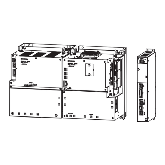
4.4 Main Circuit Wiring Main Circuit Wiring The names, specifications, and functions of the main circuit terminals required for trial operation are given below. 4.4.1 Names and Functions of Main Circuit Terminals Multi-Winding Drive Unit The following figure shows the appearance of a multi-winding drive unit. Note: For the purpose of this description, the multi-winding drive unit is shown with the front cover removed. - Page 55 4 Wiring and Connection 4.4.1 Names and Functions of Main Circuit Terminals SERVOPACK The following figure shows the appearance of a SERVOPACK. Note: For the purpose of this description, the SERVOPACK is shown with the front cover removed. Always keep the front cover attached when using the SERVOPACK. SERVOPACK CN115 CN103, CN104...
- Page 56 4.4 Main Circuit Wiring Converter The following figure shows the appearance of the converter. Note: For the purpose of this description, the converter is shown with the front cover removed. Always keep the front cover attached when using the converter. Converter CN101 CN103, CN104...
-
Page 57: Connecting The Connectors
4 Wiring and Connection 4.4.2 Connecting the Connectors (cont’d) Terminals Name Specifications CN103 and CN104 output 24 VDC to the SERVO- PACK. CN103, Control power output For a 400-V system, the 24-VDC (±15%) input is output CN104 connectors unaltered from CN103. CN104 provides the same out- put, but it is normally not necessary to connect it. -
Page 58: Interconnecting Terminals
4.4 Main Circuit Wiring 4.4.3 Interconnecting Terminals Use the bus bars that are provided with the converter to connect the P and N terminals between the SERVOPACK and the converter. The bus bars can be connected in any direction. 4-15... -
Page 59: Main Circuit Wires
4 Wiring and Connection 4.4.4 Main Circuit Wires 4.4.4 Main Circuit Wires Use the following wires for the main circuits of the multi-winding drive unit, SERVOPACKs, and the converters. 1. Wire sizes are selected for three cables per bundle at 40°C sur- rounding air temperature with the rated current. - Page 60 *1, *2 Terminals (AWG) Model Model – 1.25 CN7A/B – – – (connector) (16) 1.2 to 1.4 R2-4 YHT-2210 (14) ∗1. Use the crimp terminals that are recommended by Yaskawa or an equivalent. ∗2. Manufactured by J.S.T. Mfg. Co., Ltd. 4-17...
- Page 61 (24 V, 0 V) (Connector) B1, B2 12 to 20 8 (8) R8-10 9.0 to 11.0 38 (1) R38-8 ∗1. Use SERVOPACKs and converters in the specified combinations. ∗2. Use the crimp terminals that are recommended by Yaskawa or an equivalent. 4-18...
- Page 62 4.4 Main Circuit Wiring Tools for Crimp Terminals Tools (by J.S.T. Mfg Co., Ltd.) Model Body Head Dies R2-4 YHT-2210 – – R3.5-6 YHT-8S – – R8-10 YPT-150-1 – TD-221, TD-211 Body only: YPT-150-1 R38-8 TD-224, TD-212 R38-10 Body: YF-1; Head: YET-150-1 Wire Size (UL Standard) To comply with the UL standard, use the recommended wires.
- Page 63 4 Wiring and Connection 4.4.4 Main Circuit Wires Crimp Terminal, Sleeve, Terminal Kit Crimp Sleeve Model Terminal Combination of (Made by Terminal Model (Made SERVOPACK and Terminal Kit Model Tokyo Dip Symbols by J.S.T. Mfg Converter Co., Ltd.) Co., Ltd.) U, V, W R60-8 TP-060 (black)
-
Page 64: 4.4.5 Typical Main Circuit Wiring Examples
4.4 Main Circuit Wiring 4.4.5 Typical Main Circuit Wiring Examples CAUTION • Be sure to observe the following precautions when wiring the main circuit termi- nals and connectors on a multi-winding drive unit, SERVOPACK, or converter. • Do not turn ON the power to a multi-winding drive unit, SERVOPACK, or converter until all wiring, including the wiring to the main circuit connector, has been com- pleted. -
Page 65: 4.4.5 Typical Main Circuit Wiring Examples
4 Wiring and Connection 4.4.5 Typical Main Circuit Wiring Examples A wiring example is provided below for the multi-winding drive unit, SERVO- PACKs, and converters. Power supply: Three-phase 400 VAC R S T Converter SERVOPACK No. 1 CN101 CN103 CN103 CN901 CN901 1FLT... -
Page 66: Selecting And Connecting A Regenerative Resistor Unit
The regenerative resistor units specified by Yaskawa are listed in the following table. You must acquire the regenerative resistor units separately. If you use a regenerative resistor unit specified by Yaskawa, use it only in one of the combinations that are given in the following table. -
Page 67: Connecting A Regenerative Resistor Unit
4 Wiring and Connection 4.5.2 Connecting a Regenerative Resistor Unit Using a Non-Specified Regenerative Resistor Unit If you use non-specified regenerative resistor units, contact your Yaskawa representa- tive or the sales department for more details. Main Circuit Power SERVOPACK Converter Model:... -
Page 68: Setting Regenerative Resistor Capacity
Observe the following installation standards when you use a regenerative resistor unit specified by Yaskawa. Provide at least 70 mm on each side of the unit and at least 200 mm at both the top and bottom of the unit to enable fan and natural convection cool- ing. -
Page 69: Selecting And Connecting A Dynamic Brake Unit
Note: The allowable load moment of inertia calculated at the motor shaft is five times the ser- vomotor moment of inertia. 4.6.2 Connecting a Dynamic Brake Unit Using a Dynamic Brake Unit from Yaskawa When connecting a dynamic brake, refer to the following diagram. Dynamic brake unit SERVOPACK... - Page 70 4.6 Selecting and Connecting a Dynamic Brake Unit Using a Dynamic Brake Unit from Another Company • Using NO Contacts for the Dynamic Brake Contactor For I/O SERVOPACK power supply 24 V Dynamic brake contactor (Auxiliary contacts) Dynamic brake resistor CN115 24 V DB24...
- Page 71 4 Wiring and Connection 4.6.2 Connecting a Dynamic Brake Unit • Using NC Contacts for the Dynamic Brake Contactor For I/O SERVOPACK power supply 24 V Dynamic brake contactor (Auxiliary contacts) Dynamic brake resistor CN115 24 V DB24 DBON Main circuit surge absorption unit Coil surge absorption unit...
-
Page 72: Installation Standards
4.6.3 Installation Standards Observe the following installation standards when you use a Yaskawa dynamic brake unit. Provide at least 70 mm on each side of the unit and at least 200 mm at both the top and bottom of the unit to enable fan and natural convection cooling. -
Page 73: Safety Function
Safety Function This chapter describes the safety functions. 5.1 Outline ..........5-2 5.2 Hard Wire Base Block (HWBB) Function . -
Page 74: Outline
5 Safety Function Outline A safety function is incorporated in the multi-winding drive unit, SERVOPACKs, and converters to reduce the risk associated with the machine by protecting workers from injury due to hazardous operation of the moving part of the machine and by securing safe machine operation. -
Page 75: Hard Wire Base Block (Hwbb) Function
5.2 Hard Wire Base Block (HWBB) Function Hard Wire Base Block (HWBB) Function The Hard Wire Base Block function (hereinafter referred to as HWBB function) is a safety function designed to baseblock the motor (shut off the motor current) by using the hardwired circuits: Each circuit for two channel input signals blocks the run sig- nal to turn OFF the power module, and the motor current is shut off. -
Page 76: Safety Function Signal (Cn8) Names And Functions
5 Safety Function Note: For the safety function signal connections, the input signal is the 0 V common and the output signal is the source output. This is opposite to other signals described in this man- ual. To avoid confusion, the ON and OFF status of signals for the safety functions are defined as follows: ON: The state in which the relay contacts are closed or the transistor is ON and current flows into the signal line. -
Page 77: Precautions When Not Using The Safety Function
5.4 Precautions When Not Using the Safety Function Precautions When Not Using the Safety Function When not using the safety function or when performing a JOG operation, use the SERVOPACK with the safety function’s jumper connector (provided as an acces- sory) inserted into CN8. - Page 78 5 Safety Function Connect the safety function device to the safety connector (CN8). Note:If you do not connect a safety function device, leave the safety function's jumper connector connected to the safety connector (CN8). If the SERVOPACK is used without the safety function's jumper connector connected to CN8, no current will be supplied to the servomotor and no motor torque will be output.
-
Page 79: Trial Operation (Checking Servomotor Operation)
Trial Operation (Checking Servomotor Operation) This chapter describes how to perform trial operation. 6.1 Outline ..........6-2 6.2 Inspection and Checking before Trial Operation . -
Page 80: Outline
6 Trial Operation (Checking Servomotor Operation) Outline The trial operation described here is a JOG operation for servomotors not connected to machinery (without a load). The purpose of this trial operation is to check whether the multi-winding drive unit, SERVOPACKs, converters, and servomotor are prop- erly connected and whether the servomotor is operating normally. -
Page 81: Inspection And Checking Before Trial Operation
6.2 Inspection and Checking before Trial Operation Inspection and Checking before Trial Operation To ensure safe and correct trial operation, inspect and check the following items before starting trial operation. Servomotors Inspect and check the following items, and take appropriate measures before per- forming trial operation if any problem exists. - Page 82 6 Trial Operation (Checking Servomotor Operation) Multi-Winding Drive Unit, SERVOPACKs, and Converters Inspect and check the following items, and take appropriate measures before per- forming trial operation if any problem exists. • Are all installation, wiring and connections correct? •...
- Page 83 6.2 Inspection and Checking before Trial Operation Checking the Main Circuit Power Supply, Servomotor, Multi-Winding Drive Unit, and Encoder Wiring Once again, check the main circuit power supply, servomotor, multi-winding drive unit, and encoder wiring that was described in Chapter 4 Wiring and Connection. Perform a trial operation with the safety function jumper connector (provided as an accessory) inserted into the CN8 connector.
-
Page 84: Jog Operation Using A Panel Operator
6 Trial Operation (Checking Servomotor Operation) JOG Operation Using a Panel Operator This section describes the procedure for executing a JOG operation using a panel operator. The operating section of the panel operator is behind the plastic plate at the top of the front of the multi-winding drive unit. - Page 85 6.3 JOG Operation Using a Panel Operator (cont’d) Step Display after operation Keys Operation Press the DATA/SHIFT Key for approxi- mately one second. The display shown on the left appears. MODE/SET DATA/ Press the MODE/SET Key to turn the servomotor power ON. MODE/SET DATA/ The servomotor will rotate at the speed...
-
Page 86: Jog Operation Using A Digital Operator
6 Trial Operation (Checking Servomotor Operation) JOG Operation Using a Digital Operator This section describes the procedure for executing a JOG operation using a digital operator. Connect a digital operator to the CN54 connector on the multi-winding drive unit. Note: You must use a JUSP-OP05A-E digital operator for the multi-winding drive unit. Digital operator (model: JUSP-OP05A-1-E) JUSP-MD... - Page 87 6.4 JOG Operation Using a Digital Operator (cont’d) Step Display after operation Keys Operation − J O G − P n 3 0 4 = 0 0 5 0 0 Press the Key. U n 0 0 0 = 0 0 0 0 0 The display changes to the execution display of Fn002.
- Page 88 6 Trial Operation (Checking Servomotor Operation) (cont’d) Step Display after operation Keys Operation After having confirmed the correct motion of servomotor, press the − J O G − 46 and 64 P n 3 0 4 = 0 1 0 0 0 Key.
-
Page 89: Jog Operation Using Sigmawin
6.5 JOG Operation Using SigmaWin+ JOG Operation Using SigmaWin+ This section describes the procedure for executing a JOG operation using Sig- maWin+. In the following example, procedures for trial operation are explained using the JOG operation window of Test Run on the main menu of SigmaWin+. Step Operation Display... - Page 90 6 Trial Operation (Checking Servomotor Operation) (cont’d) Step Operation Display (4) Double click the SigmaWin+ icon to dis- play the SigmaWin+ startup screen. SigmaWin+ English Edition (cont’d) Startup Screen (5) Once SigmaWin+ is started, the connec- tion window is displayed. Note: is used for operation with no SERVOPACK connected.
- Page 91 6.5 JOG Operation Using SigmaWin+ (cont’d) Step Operation Display (6) Search Condition Setting window is open. Select only Σ-V Select Σ-V( ), and click A dialog box will open first to tell you a search has started, and then the search result will be shown in the connection window.
- Page 92 6 Trial Operation (Checking Servomotor Operation) (cont’d) Step Operation Display • Trial operation. Test Run (R) → Jog (J) (1) Select Test Run (R) first, and then select Jog (J) from the menu on the main win- dow. Main Window (2) Warnings for the JOG operation window will be displayed.
- Page 93 6.5 JOG Operation Using SigmaWin+ (cont’d) Step Operation Display • Set the JOG speed The motor speed is set to 500 [min ]. Click if you need to change it. • Servo ON Click . The display changes from Servo OFF to Servo ON and is lit in green. 6-15...
- Page 94 6 Trial Operation (Checking Servomotor Operation) (cont’d) Step Operation Display • Start JOG operation. When you click the servomotor will rotate in the forward direction. When you click it will rotate in reverse. Confirm that the servomotor operation is cor- rect.
-
Page 95: Revision History
Revision History The revision dates and numbers of the revised manuals are given at the bottom of the back cover. MANUAL NO. SIEP S800001 85B <1> Revision number Published in Japan July 2016 Date of publication Date of Rev. Section Revised Contents Publication February 2018... - Page 96 Phone: +81-4-2962-5151 Fax: +81-4-2962-6138 http://www.yaskawa.co.jp YASKAWA AMERICA, INC. 2121, Norman Drive South, Waukegan, IL 60085, U.S.A. Phone: +1-800-YASKAWA (927-5292) or +1-847-887-7000 Fax: +1-847-887-7310 http://www.yaskawa.com YASKAWA ELÉTRICO DO BRASIL LTDA. 777, Avenida Piraporinha, Diadema, São Paulo, 09950-000, Brasil Phone: +55-11-3585-1100 Fax: +55-11-3585-1187 http://www.yaskawa.com.br...
Need help?
Do you have a question about the Sigma-V Series and is the answer not in the manual?
Questions and answers