YASKAWA Σ-V Series User Manual
Ac servo drives; linear motor command option attachable type
Hide thumbs
Also See for Σ-V Series:
- User manual (242 pages) ,
- Safety precautions (33 pages) ,
- User manual (320 pages)
Table of Contents
Advertisement
AC Servo Drives
Σ-V
Series
USER'S MANUAL
Design and Maintenance
Linear Motor
Command Option Attachable Type
SGDV SERVOPACK
SGLGW/SGLFW/SGLTW/SGLCW/SGT Servomotors
MANUAL NO. SIEP S800000 66A
Outline
Panel Display and
Operation of Digital Operator
Wiring and Connection
Operation
Adjustments
Utility Functions (Fn)
Monitor Modes (Un)
Troubleshooting
Appendix
1
2
3
4
5
6
7
8
9
Advertisement
Table of Contents
Troubleshooting

Subscribe to Our Youtube Channel
Related Manuals for YASKAWA Σ-V Series


Summary of Contents for YASKAWA Σ-V Series
- Page 1 AC Servo Drives Σ-V Series USER'S MANUAL Design and Maintenance Linear Motor Command Option Attachable Type SGDV SERVOPACK SGLGW/SGLFW/SGLTW/SGLCW/SGT Servomotors Outline Panel Display and Operation of Digital Operator Wiring and Connection Operation Adjustments Utility Functions (Fn) Monitor Modes (Un) Troubleshooting Appendix MANUAL NO.
- Page 2 Yaskawa. No patent liability is assumed with respect to the use of the information contained herein. Moreover, because Yaskawa is con- stantly striving to improve its high-quality products, the information contained in this manual is subject to change without notice.
-
Page 3: About This Manual
About this Manual This manual describes informations required for designing, and maintaining Σ-V Series SERVOPACKs. Be sure to refer to this manual and perform design and maintenance to select devices correctly. Keep this manual in a location where it can be accessed for reference whenever required. Description of Technical Terms The following table shows the meanings of terms used in this manual. - Page 4 Example Digital Operator Display Notation Example for Pn000 Pn000 Digit Notation Set Value Notation Meaning Notation Method Notation Method Meaning Indicates that digit 1 of the Indicates digit 1 Pn000.0 = x Digit 1 Pn000.0 or n. parameter (Pn000) is x. of the parameter (Pn000).
- Page 5 Manuals Related to the Σ-V Series Refer to the following manuals as required. Selecting Trial Maintenance Models and Ratings and Panels and Trial Operation Name Peripheral Specifications Wiring Operation and Servo Inspection Devices Adjustment Σ-V Series User's Manual Setup Linear Motor (SIEP S800000 44) Σ-V Series Product Catalog...
- Page 6 Safety Information The following conventions are used to indicate precautions in this manual. Failure to heed precautions pro- vided in this manual can result in serious or possibly even fatal injury or damage to the products or to related equipment and systems. Indicates precautions that, if not heeded, could possibly result in loss of WARNING life or serious injury.
-
Page 7: Safety Precautions
Safety Precautions These safety precautions are very important. Read them before performing any procedures such as storage and transportation, installation, wiring, operation, maintenance and inspection, or disposal. Be sure to always observe these precautions thoroughly. WARNING • If you have a pacemaker or any other electronic medical device, do not go near the magnetic way of the linear servomotor. - Page 8 Storage and Transportation CAUTION • Be sure to store the magnetic way in the package that was used for delivery. • Do not store or install the product in the following locations. Failure to observe this caution may result in fire, electric shock, or damage to the product. •...
- Page 9 Installation CAUTION • When unpacking and installing magnetic way, check that there is no metal fragments or magnetized objects near the magnetic way because they may be affected by the magnetic attraction of the mag- netic way. Failure to observe this caution may result in injury or damage to the magnetic way's magnets. •...
- Page 10 Wiring CAUTION • Securely tighten the cable connector screws and securing mechanism. If the connector screws and securing mechanism are not secure, they may loosen during operation. • Use cables with a radius, heat resistance, and flexibility suitable for the system. •...
- Page 11 Operation CAUTION • Always use the linear servomotor and SERVOPACK in one of the specified combinations. Failure to observe this caution may result in fire or malfunction. • Do not stand within the machine's range of motion during operation. Failure to observe this caution may result in injury. •...
- Page 12 • The drawings presented in this manual are typical examples and may not match the product you received. • If the manual must be ordered due to loss or damage, inform your nearest Yaskawa representative or one of the offices listed on the back of this manual.
-
Page 13: Warranty
6. Events for which Yaskawa is not responsible, such as natural or human-made disasters (2) Limitations of Liability 1. Yaskawa shall in no event be responsible for any damage or loss of opportunity to the customer that arises due to failure of the delivered product. - Page 14 2. The customer must confirm that the Yaskawa product is suitable for the systems, machines, and equipment used by the customer. 3. Consult with Yaskawa to determine whether use in the following applications is acceptable. If use in the application is acceptable, use the product with extra allowance in ratings and specifications, and provide safety measures to minimize hazards in the event of failure.
-
Page 15: Applicable Standards
Applicable Standards North American Safety Standards (UL) ∗ Standards Model (UL File No.) SERVOPACK • SGDV UL508C (E147823) ∗ Underwriters Laboratories Inc. European Standards EMC Directive Low Voltage Safety Model Directive Standards EN55011/A2 EN50178 EN61800-3 EN954-1 SERVOPACK • SGDV group 1 class A EN61000-6-2 IEC61508-1 to 4 EN61800-5-1... -
Page 16: Table Of Contents
Contents About this Manual ............iii Safety Precautions. - Page 17 Chapter 3 Wiring and Connection ....... 3-1 3.1 Main Circuit Wiring..........3-2 3.1.1 Main Circuit Terminals .
- Page 18 4.4 Limiting Force ..........4-30 4.4.1 Internal Force Limit .
- Page 19 5.9 Compatible Adjustment Function ....... . . 5-60 5.9.1 Feedforward Reference ..........5-60 5.9.2 Using the Mode Switch (P/PI Switching) .
- Page 20 Chapter 9 Appendix......... . 9-1 9.1 List of Parameters .
- Page 21 Outline 1.1 Σ-V Series SERVOPACKs ........1-2 1.2 Part Names .
-
Page 22: Σ-V Series Servopacks
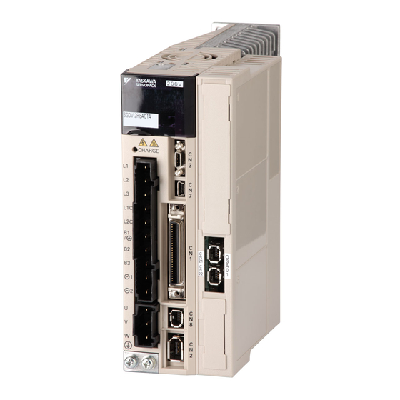
1 Outline Σ-V Series SERVOPACKs The Σ-V Series SERVOPACKs are designed for applications that require frequent high-speed, high-pre- cision positioning. The SERVOPACK makes the most of machine performance in the shortest time possi- ble, thus contributing to improving productivity. Part Names This section gives the part names of the SGDV SERVOPACK (command option attachable type). -
Page 23: Servopack Ratings And Specifications
1.3 SERVOPACK Ratings and Specifications SERVOPACK Ratings and Specifications This section describes the ratings and specifications of SERVOPACKs. 1.3.1 Ratings Ratings of SERVOPACKs are as shown below. (1) SGDV Single-phase 100-V Ratings SGDV (Single-phase, 100 V) Continuous Output Current 0.66 0.91 [Arms] Max. - Page 24 1 Outline 1.3.1 Ratings (4) SGDV Three-phase 400-V Ratings SGDV (Three-phase, 400 V) Continuos Output Current 11.9 16.5 25.7 [Arms] Max. Output Current [Arms] Built-in/External External Regenerative Resistor +10% Main Circuit Power Supply Three-phase, 380 to 480 VAC , 50/60 Hz −15% Control Power 24 VDC ±15%...
-
Page 25: Basic Specifications
1.3 SERVOPACK Ratings and Specifications 1.3.2 Basic Specifications Basic specifications of SERVOPACKs are shown below. Control Method IGBT-PWM (sine-wave driven) • Absolute linear scale Signal resolution = Sine-wave pitch of absolute linear scale /Number of divisions in absolute linear scale Feedback •... - Page 26 1 Outline 1.3.2 Basic Specifications Phase-A, -B, -C: line driver Encoder Output Pulses Encoder output pulse: any setting ratio Number 7 channels Channels Input Sequence Signals The signal allocation and positive/negative logic can be Input which can modified. be allocated Forward run prohibited (P-OT), reverse run prohibited (N- Functions OT), forward force limit (/P-CL), reverse force limit (/N-CL),...
- Page 27 1.3 SERVOPACK Ratings and Specifications ∗1. Signal resolution differs in accordance with the absolute linear scale. ∑ ∗2. Signal resolution differs in accordance with the serial converter unit. For more information, refer to -V Series Product Catalog (KAEP S800000 42.) ∗3.
-
Page 28: Servopack Internal Block Diagrams
1 Outline 1.4.1 Single-phase 100-V, SGDV-R70FE5A, -R90FE5A, -2R1FE5A Models SERVOPACK Internal Block Diagrams 1.4.1 Single-phase 100-V, SGDV-R70FE5A, -R90FE5A, -2R1FE5A Models Linear servomotor + 12 V Varistor Main circuit power supply − − Dynamic brake circuit Gate drive Temperature Voltage Relay Voltage Gate Current... -
Page 29: Single-Phase 200-V, Sgdv-120Ae5A008000 Model
1.4 SERVOPACK Internal Block Diagrams 1.4.3 Single-phase 200-V, SGDV-120AE5A008000 Model Fan 1 Fan 2 Linear servomotor Varistor ±12V ±12V Main circuit power supply − Overheat protector, Dynamic overcurrent protector brake circuit Current Voltage Relay Voltage Gate drive sensor sensor drive sensor Varistor +15V ×... -
Page 30: Three-Phase 200-V, Sgdv-2R8Ae5A Model
1 Outline 1.4.5 Three-phase 200-V, SGDV-2R8AE5A Model 1.4.5 Three-phase 200-V, SGDV-2R8AE5A Model Linear servomotor Varistor + 12 V Main circuit power supply − Dynamic brake circuit Gate drive Temperature Current Voltage Relay Voltage Gate overcurrent sensor sensor drive protector sensor drive sensor Varistor... -
Page 31: Three-Phase 200-V, Sgdv-120Ae5A Model
1.4 SERVOPACK Internal Block Diagrams 1.4.7 Three-phase 200-V, SGDV-120AE5A Model Linear servomotor Varistor ±12V Main circuit power supply − Overheat protector, Dynamic overcurrent protector brake circuit Current Voltage Relay Voltage Gate drive sensor sensor drive sensor Varistor +15V × 4 Control Analog Analog monitor... -
Page 32: Three-Phase 200-V, Sgdv-330Ae5A Model
1 Outline 1.4.9 Three-phase 200-V, SGDV-330AE5A Model 1.4.9 Three-phase 200-V, SGDV-330AE5A Model Fan 1 Fan 2 Linear servomotor Varistor ±12V ±12V Main circuit − power supply Overheat protector, Dynamic overcurrent protector brake circuit Temperature Current Voltage Thyristor Voltage Gate drive sensor senser sensor... -
Page 33: Three-Phase 400-V, Sgdv-1R9De5A, -3R5De5A, -5R4De5A Models
1.4 SERVOPACK Internal Block Diagrams 1.4.11 Three-phase 400-V, SGDV-1R9DE5A, -3R5DE5A, -5R4DE5A Models Linear servomotor Varistor ±12V − Main circuit power supply − Overheat protector, Dynamic overcurrent protector brake circuit Voltage Relay Voltage sensor Current drive sensor Gate drive sensor +24V +15V ×... -
Page 34: Three-Phase 400-V, Sgdv-170De5A Model
1 Outline 1.4.13 Three-phase 400-V, SGDV-170DE5A Model 1.4.13 Three-phase 400-V, SGDV-170DE5A Model Linear servomotor ±12V Varistor − Main circuit power supply − Overheat protector, Dynamic overcurrent protector brake circuit Relay Voltage Current Gate drive sensor drive sensor Voltage sensor +24V +15V ×... -
Page 35: Examples Of Servo System Configurations
1.5 Examples of Servo System Configurations Examples of Servo System Configurations This section describes examples of basic servo system configuration. 1.5.1 Connecting to SGDV- FE5A SERVOPACK Power supply Single-phase 100 VAC Molded-case circuit breaker (MCCB) Protects the power supply line by shutting the circuit OFF when overcurrent is detected. -
Page 36: Ae5A Servopack
1 Outline 1.5.2 Connecting to SGDV- AE5A SERVOPACK 1.5.2 Connecting to SGDV- AE5A SERVOPACK (1) Using a Three-phase, 200-V Power Supply Power supply Three-phase 200 VAC R S T Molded-case circuit breaker (MCCB) Protects the power supply line by shutting the circuit OFF when overcurrent is detected. - Page 37 1.5 Examples of Servo System Configurations (2) Using a Single-phase, 200-V Power Supply The Σ-V Series SERVOPACK for a 200-V power supply input has input specifications for a three-phase power supply, but some models can also be used with a single-phase 200-V power supply. For details, refer to 3.1.4 Using the SERVOPACK with Single-phase, 200-V Power Input.
-
Page 38: Connecting To Sgdv- De5A Servopack
1 Outline 1.5.3 Connecting to SGDV- DE5A SERVOPACK 1.5.3 Connecting to SGDV- DE5A SERVOPACK Power supply Three-phase 400 VAC R S T Molded-case circuit breaker (MCCB) Protects the power supply line by shutting the circuit OFF when overcurrent is detected. Noise filter Used to eliminate Digital... -
Page 39: Servopack Model Designation
1.6 SERVOPACK Model Designation SERVOPACK Model Designation Select the SERVOPACK according to the applied servomotor. 13th 8th + 9th + 11th + 12th 5th + 6th 1st + 2nd + digit 10th digits digits digit digit digits 3rd digits SGDV –... -
Page 40: Inspection And Maintenance
Refer to the standard replacement period in the following table, contact your Yaskawa representative. After an examination of the part in question, we will determine whether the parts should be replaced or not. - Page 41 Panel Display and Operation of Digital Operator 2.1 Panel Display ..........2-2 2.1.1 Status Display .
-
Page 42: Panel Display
2 Panel Display and Operation of Digital Operator 2.1.1 Status Display Panel Display The servo status can be checked on the panel display of the SERVOPACK. Also, if an alarm or warning occurs, its alarm or warning number is displayed. 2.1.1 Status Display The display shows the following status. -
Page 43: Utility Function Mode (Fn )
2.2 Utility Function Mode (Fn Utility Function Mode (Fn The setup and adjustment functions of the SERVOPACK are executed in this mode. The digital operator displays numbers beginning with Fn. An operation example in Utility Function Mode is shown below for Origin Search (Fn003). Step Display after Operation Keys... -
Page 44: Parameter
2 Panel Display and Operation of Digital Operator 2.3.1 Parameter Classifications Parameter (Pn ) Operation This section describes the classifications, notation, and setting methods of parameters given in this manual. 2.3.1 Parameter Classifications The Σ-V-series SERVOPACKs have two types of parameters: setup parameters for the basic settings required for opera- tion and tuning parameters for adjusting servo performance. -
Page 45: Parameter Setting Methods
2.3 Parameter (Pn ) Operation 2.3.3 Parameter Setting Methods (1) Setting Method for Numeric Parameters The following example shows how to change the setting of parameter Pn383 (JOG speed) to 1000 mm/s. Step Display after Operation Keys Description Press the Key to select the Parameter/Monitor Mode. - Page 46 2 Panel Display and Operation of Digital Operator 2.3.3 Parameter Setting Methods (2) Setting Method for Selection Parameters The following example shows how to use application function selection switch 1 (Pn001) to change the setting for the stopping method at servo OFF and alarm occurrence from stopping using DB (Pn001 = n.0000) to stopping without DB (Pn001 = n.0002).
-
Page 47: Monitor Mode (Un )
2.4 Monitor Mode (Un Monitor Mode (Un The monitor mode can be used for monitoring the reference values, I/O signal status, and SERVOPACK inter- nal status. For details, refer to 7.2 Monitor Displays. The digital operator display numbers begin with Un. The following four Un numbers are displayed with the factory settings. - Page 48 Wiring and Connection 3.1 Main Circuit Wiring ......... . 3-2 3.1.1 Main Circuit Terminals .
-
Page 49: Chapter 3 Wiring And Connection
3 Wiring and Connection 3.1.1 Main Circuit Terminals Main Circuit Wiring The names and specifications of the main circuit terminals are given on the following page. This section also describes the general precautions for wiring and precautions under special environments. 3.1.1 Main Circuit Terminals The names and specifications are shown in the following table. -
Page 50: Using A Standard Power Supply Input (Single-Phase 100-V, Three-Phase 200-V, Or Three-Phase 400-V)
3.1 Main Circuit Wiring Terminal Symbols Name Model SGDV- Description Main circuit plus terminal Use when DC power supply input is used. Main circuit 2 or minus terminal Linear servomotor U, V, W Use for connecting to the linear servomotor. connection terminals Ground... - Page 51 3 Wiring and Connection 3.1.2 Using a Standard Power Supply Input (Single-phase 100-V, Three-phase 200-V, or Three-phase 400-V) (2) SERVOPACK Main Circuit Wire This section describes the wire used for the SERVOPACK main circuit. 1. Wire sizes are selected for three cables per bundle at 40°C surrounding air tempera- ture with the rated current.
- Page 52 3.1 Main Circuit Wiring (3) Typical Main Circuit Wiring Examples Note the following points when designing the power ON sequence. • Design the power ON sequence so that main power is turned OFF when a servo alarm signal is output. •...
- Page 53 3 Wiring and Connection 3.1.2 Using a Standard Power Supply Input (Single-phase 100-V, Three-phase 200-V, or Three-phase 400-V) Single-phase 100 V, SGDV- F (SGDV-R70F, R90F, 2R1F, 2R8F) SERVOPACK SGDV- 1FLT +24V (For servo ALM+ alarm display) ALM− Servo power Servo power supply ON supply OFF 1QF: Molded-case circuit breaker...
- Page 54 3.1 Main Circuit Wiring • SGDV-550A R S T SERVOPACK SGDV- 1FLT +24 V (For servo alarm display) ALM+ Servo power Servo power ALM− supply ON supply OFF Regenerative resistor unit 1PL: Indicator lamp 1QF: Molded-case circuit breaker 1FLT: Noise filter 1SA: Surge absorber 1KM: Magnetic contactor (for control power supply) 2SA: Surge absorber...
- Page 55 3 Wiring and Connection 3.1.2 Using a Standard Power Supply Input (Single-phase 100-V, Three-phase 200-V, or Three-phase 400-V) • SGDV-260D R S T SERVOPACK SGDV- 1FLT DC power supply − (24 V) +24 V (For servo alarm display) ALM+ Servo power Servo power ALM−...
- Page 56 3.1 Main Circuit Wiring (4) Power Supply Capacities and Power Losses The following table gives the power capacities and power losses of the SERVOPACK. Maximum Power Sup- Main Regener- Control SERVO- Total Main Circuit Applicable ply Capacity Output Circuit ative Circuit PACK Power...
- Page 57 3 Wiring and Connection 3.1.2 Using a Standard Power Supply Input (Single-phase 100-V, Three-phase 200-V, or Three-phase 400-V) (5) Molded-case Circuit Breaker and Fuse Capacities The following table describes the molded-case circuit breaker and fuse capacities of the SERVOPACK. Maximum Current Capacity Inrush Current Power Supply...
-
Page 58: General Precautions For Wiring
3.1 Main Circuit Wiring 3.1.3 General Precautions for Wiring Use a molded-case circuit breaker (1QF) or fuse to protect the main circuit. • The SERVOPACK connects directly to a commercial power supply; it is not isolated through a transformer or other device. Always use a molded-case circuit breaker (1QF) or fuse to protect the servo system from accidents involving different power system voltages or other accidents. -
Page 59: Using The Servopack With Single-Phase, 200-V Power Input
3 Wiring and Connection 3.1.4 Using the SERVOPACK with Single-phase, 200-V Power Input 3.1.4 Using the SERVOPACK with Single-phase, 200-V Power Input Some models of Σ-V series three-phase 200 V power input SERVOPACK can be used also with a single-phase 200 V power supply. - Page 60 3.1 Main Circuit Wiring (3) SERVOPACK Main Circuit Wire Model SGDV- Terminal Name Symbols 120* Main circuit power input L1, L2 HIV1.25 HIV2.0 HIV3.5 terminals Control power supply input L1C, L2C HIV1.25 terminals U, V, W Motor connection terminals HIV1.25 HIV2.0 External regenerative resistor HIV1.25...
- Page 61 3 Wiring and Connection 3.1.4 Using the SERVOPACK with Single-phase, 200-V Power Input (5) Power Supply Capacities and Power Losses The following table shows SERVOPACK’s power supply capacities and power losses when using a single- phase 200 V power supply. Maximum Power Supply Regenerative...
-
Page 62: Using The Servopack With A Dc Power Input
3.1 Main Circuit Wiring 3.1.5 Using the SERVOPACK with a DC Power Input (1) Parameter Settings When using the SERVOPACK with a DC power input, set parameter Pn001.2 to 1. Parameter Meaning When Enabled Classification n. 0 Enables use of AC power input. Pn001 After restart Setup... - Page 63 3 Wiring and Connection 3.1.5 Using the SERVOPACK with a DC Power Input (3) Wiring Examples with DC Power Supply Input SERVOPACK SGDV- A with 200-V Power Supply Input R S T SERVOPACK SGDV- 1FLT AC/DC +24 V ALM+ (For servo alarm display) ALM−...
-
Page 64: Using More Than One Servopack
3.1 Main Circuit Wiring 3.1.6 Using More Than One SERVOPACK This section shows an example of the wiring when more than one SERVOPACK is used and the precautions. (1) Wiring Example Connect the alarm output (ALM) terminals for the three SERVOPACKs in series to enable alarm detection relay 1Ry to operate. -
Page 65: I/O Signal Connections
3 Wiring and Connection 3.2.1 I/O Signal (CN1) Names and Functions I/O Signal Connections This section describes the names and functions of I/O signals (CN1). Also, connection examples by control method are shown. 3.2.1 I/O Signal (CN1) Names and Functions The following table shows the names and functions of I/O signals (CN1). -
Page 66: Safety Function Signal (Cn8) Names And Functions
3.2 I/O Signal Connections 3.2.2 Safety Function Signal (CN8) Names and Functions The following table shows the terminal layout of safety function signals (CN8). Signal Pin No. Name Function /HWBB1+ Hard wire base block input 1 Hard wire base block input /HWBB1- Base Block (motor current off) when /HWBB2+... -
Page 67: Example Of I/O Signal Connections
3 Wiring and Connection 3.2.3 Example of I/O Signal Connections 3.2.3 Example of I/O Signal Connections The following diagram shows a typical connection example. Photocoupler output Max. operating voltage: 30 VDC Max. operating current: 50 mA DC SGDV SERVOPACK 3.3kΩ +24V ALM+ Control power supply... -
Page 68: I/O Signal Allocations
3.3 I/O Signal Allocations I/O Signal Allocations This section describes the I/O signal allocations. 3.3.1 Input Signal Allocations Input signals are allocated as shown in the following table. Refer to the Interpreting the Input Signal Allocation Tables and change the allocations accordingly. <Interpreting the Input Signal Allocation Tables>... - Page 69 3 Wiring and Connection 3.3.1 Input Signal Allocations Connection Not Required CN1 Pin Numbers (SERVOPACK Input Signal Names Validity Input judges the and Parameters Level Signal connection) Always Always P-OT Forward Run Prohibited Pn50A.3 /P-OT Reverse Run N-OT Prohibited /N-OT Pn50B.0 Forward External Force /P-CL...
-
Page 70: Output Signal Allocation
3.3 I/O Signal Allocations 3.3.2 Output Signal Allocation Output signals are allocated as shown in the following table. Refer to the Interpreting the Output Signal Allocation Tables and change the allocations accordingly. <Interpreting the Output Signal Allocation Tables> The parameter set values to be used are shown. Signals are allocated to CN1 pins according to the selected set values. -
Page 71: Connection To Host Controller
3 Wiring and Connection 3.4.1 Sequence Input Circuits Connection to Host Controller This section shows examples of SERVOPACK I/O signal connection to the host controller. 3.4.1 Sequence Input Circuits (1) Photocoupler Input Circuit CN1 connector terminals 6 to 13 are explained below. The sequence input circuit interface connects through a relay or open-collector transistor circuit. - Page 72 3.4 Connection to Host Controller (2) Safety Input Circuit As for wiring input signals for safety function, input signals make common 0 V. It is necessary to make an input signal redundant. Input Signal Connection Example SERVOPACK 24-V power supply Switch /HWBB1+ 4 3.3 kΩ...
-
Page 73: Sequence Output Circuits
3 Wiring and Connection 3.4.2 Sequence Output Circuits 3.4.2 Sequence Output Circuits The following diagrams show examples of how output circuits can be connected the SERVOPACK. Incorrect wiring or incorrect voltage application to the output circuit may cause short-cir- cuit. The above failures will prevent the holding brake from working, which may damage the machine or cause an accident resulting in death or injury. - Page 74 3.4 Connection to Host Controller (3) Safety Output Circuit External device monitor (EDM1), an output signal of safety function, is explained below. Connection Example The following figure shows a connection example for the EDM1 output signal. Host controller SERVOPACK 24 V power supply EDM1+ EDM1- Specifications...
-
Page 75: Wiring Communications Using Command Option Modules
3 Wiring and Connection Wiring Communications Using Command Option Modules The following diagram shows an example of connections between a host controller and a SERVOPACK using communications with Command Option Modules. Connect the connector of the communications cable to the Command Option Module. For details, refer to the manual of the connected Command Option Module. -
Page 76: Linear Scale Connections
3.6 Linear Scale Connections Linear Scale Connections This section describes the connection example of output signals between linear scale, SERVOPACK and host controller. CN2 linear scale connector terminal layout is also described. 3.6.1 Linear Scale Signal (CN2) Names and Functions The following table shows the names and functions of the linear scale signals (CN2). - Page 77 3 Wiring and Connection 3.6.2 Connection Example of a Linear Scale (2) Linear Scale Made by Renishaw Linear scale made by Renishaw Serial converter unit SERVOPACK Host controller ∗ ∗ ∗ Line receiver Phase A Phase /PAO /COS Phase B Phase /PBO Phase C...
-
Page 78: Serial Converter Unit Specifications
3.6 Linear Scale Connections (4) Absolute Linear Scale Made by Magnescale Co., Ltd. Absolue linear scale made by Magnescale SERVOPACK Co., Ltd Host controller ∗ ∗ ∗ Line receiver Phase A Phase /PAO Phase B Phase /PBO Phase C Phase /PCO Output line-driver SN75ALS194 manu-... - Page 79 3 Wiring and Connection 3.6.3 Serial Converter Unit Specifications Items Model JZDP-D00 - Model JZDP-G00 - Surrounding Air 0 °C to 55 °C Temperature Environmental Storage Temperature -20 °C to +80 °C Conditions Humidity 20 % to 90 %RH (without condensation) ∗1.
-
Page 80: Regenerative Resistors Connections
3.7 Regenerative Resistors Connections Regenerative Resistors Connections If the ability to absorb regenerative energy is insufficient, connect an external regenerative resistor in the fol- lowing manner and set the regenerative resistor capacity in Pn600. As for precautions on selecting a regenera- Σ... - Page 81 400 V Connect a regenerative resistor unit between the B1 and B2 terminals. When using a regenerative resistor unit, use the factory setting for Pn600. If a non-Yaskawa regenerative resis- tor is used, make the setting for Pn600. SERVOPACK...
-
Page 82: Setting Regenerative Resistor Capacity
3.7 Regenerative Resistors Connections 3.7.2 Setting Regenerative Resistor Capacity When an external regenerative resistor is connected, make sure to set the regenerative resistor capacity using the parameter Pn600. WARNING • If parameter Pn600 is set to 0 while an external regenerative resistor is connected, the generative over- load alarm (A.320) may not be detected. -
Page 83: Noise Control And Measures For Harmonic Suppression
3 Wiring and Connection 3.8.1 Wiring for Noise Control Noise Control and Measures for Harmonic Suppression This section describes the wiring for noise control and the DC reactor for harmonic suppression. 3.8.1 Wiring for Noise Control • Because the SERVOPACK is designed as an industrial device, it provides no mecha- nism to prevent noise interference. - Page 84 3.8 Noise Control and Measures for Harmonic Suppression (1) Noise Filter The SERVOPACK has a built-in microprocessor (CPU), so protect it from external noise as much as possible by installing a noise filter in the appropriate place. The following is an example of wiring for noise control. SERVOPACK Noise filter *3 200 VAC...
-
Page 85: Precautions On Connecting Noise Filter
3 Wiring and Connection 3.8.2 Precautions on Connecting Noise Filter 3.8.2 Precautions on Connecting Noise Filter This section describes the precautions on installing a noise filter. (1) Precautions on Using Noise Filters Always observe the following installation and wiring instructions. Do not put the input and output lines in the same duct or bundle them together. - Page 86 3.8 Noise Control and Measures for Harmonic Suppression Connect the noise filter ground wire directly to the ground plate. Do not connect the noise filter ground wire to other ground wires. Wrong Correct Noise Noise Filter Filter SERVOPACK SERVOPACK SERVOPACK SERVOPACK Shielded ground wire Ground plate...
-
Page 87: Connecting Ac/Dc Reactor For Harmonic Suppression
3 Wiring and Connection 3.8.3 Connecting AC/DC Reactor for Harmonic Suppression 3.8.3 Connecting AC/DC Reactor for Harmonic Suppression The SERVOPACK has reactor connection terminals for power supply harmonic suppression. Σ As for the precautions on selecting an AC or DC reactor and its specifications, refer to -V series Product Cat- alog (KAEP S800000 42). - Page 88 Operation 4.1 Option Module Function Settings ....... 4-3 4.1.1 Setting Switches S1 and S2 for Option Module Functions ..... 4-3 4.2 Settings for Common Basic Functions .
- Page 89 4 Operation 4.7 Safety Function ......... . . 4-41 4.7.1 Hard Wire Base Block (HWBB) Function .
-
Page 90: Option Module Function Settings
4.1 Option Module Function Settings Option Module Function Settings This section describes how to set the option module functions. 4.1.1 Setting Switches S1 and S2 for Option Module Functions The S1 and S2 Switches are used to make the settings for the Option Module Functions. S2 (factory setting) S1 (factory settings) For details on S1 and S2 switches, refer to the manual of the connected Command Option Module. -
Page 91: Settings For Common Basic Functions
4 Operation 4.2.1 Inspection and Checking before Operation Settings for Common Basic Functions This section explains the settings for the common basic functions. 4.2.1 Inspection and Checking before Operation To ensure safe and correct operation, inspect and check the following items before starting operation. (1) Linear Servomotors Inspect and check the following items and take appropriate measures before performing operation if any prob- lem exists. -
Page 92: Linear Servomotor Movement Direction
4.2 Settings for Common Basic Functions 4.2.2 Linear Servomotor Movement Direction The linear servomotor movement direction can be reversed with parameter Pn000.0. This causes the travel direction (+, -) of the shaft to reverse, but the encoder output pulse and analog monitor signal polarity do not change. -
Page 93: Overtravel
4 Operation 4.2.3 Overtravel 4.2.3 Overtravel The overtravel limit function forces the linear servomotor to stop when movable machine parts exceed the allowable range of motion by turning ON a limit switch. CAUTION • Installing Limit Switches Connect limit switches as shown below to prevent damage to the devices during linear motion. It is recommended using normally closed contacts for the limit switches to ensure safe operation in the event of a faulty contact or a disconnection in the contact. - Page 94 4.2 Settings for Common Basic Functions (3) Overtravel Function Setting Parameters Pn50A and Pn50B can be set to enable or disable the overtravel function. If the overtravel function is not used, no wiring for overtravel input signals will be required. Parameter Meaning When Enabled Classification...
- Page 95 4 Operation 4.2.3 Overtravel • A linear servomotor under force control cannot be decelerated to stop. The linear servomotor is stopped with the dynamic braking (DB) or coasts to a stop according to the setting of Pn001.0. After the linear servo- motor stops, the servomotor will enter a coast state.
-
Page 96: Electronic Gear
4.2 Settings for Common Basic Functions 4.2.4 Electronic Gear (1) Linear Scale Feedback Resolution The following table shows the pitch (Pn282) and the number of divisions for a linear scale. Linear Scale Linear Scale Serial Converter No. of Resolution Manufacturer Linear Scale Model Pitch Type... - Page 97 4 Operation 4.2.4 Electronic Gear (3) Electronic Gear Ratio Set the electric gear ratio using Pn20E and Pn210. Electronic Gear Ratio (Numerator) Position Classification Setting Range Setting Unit Factory Setting When Enabled Pn20E 1 to 1073741824 – After restart Setup Electronic Gear Ratio (Denominator) Position Classification...
- Page 98 4.2 Settings for Common Basic Functions (5) Electronic Gear Ratio Equation Refer to the following equation to determine the electronic gear ratio. <Example> When the number of divisions in the serial converter unit is 256: Linear servomotor Reference pulse Posi- Speed tion loop...
-
Page 99: Encoder Output Pulse
4 Operation 4.2.5 Encoder Output Pulse 4.2.5 Encoder Output Pulse The encoder output pulse is the signal processed by the SERVOPACK after being received from the encoder and is then output in the form of 2-phase pulses (phase A and B) with 90° phase differential to an external device. - Page 100 4.2 Settings for Common Basic Functions • Forward/Reverse Pass over 1st Zero Point Signal (Ref) after Turning Power ON Machine position (Forward direction) Time Power ON Zero point signal Phase C No zero point signal (Ref) is sent from the linear scale. Second pulse is half as wide However, a phase-C pulse will be sent from the SERVOPACK as the phase-A pulse.
-
Page 101: Encoder Output Pulse Setting
4 Operation 4.2.6 Encoder Output Pulse Setting 4.2.6 Encoder Output Pulse Setting Set the encoder output pulse using the following parameter. Encoder Output Resolution Force Speed Position Classification Pn281 Setting Range Setting Unit Factory Setting When Enabled 1 to 4096 1 edge/pitch After restart Setup... -
Page 102: Holding Brakes
4.2 Settings for Common Basic Functions 4.2.7 Holding Brakes A holding brake is a brake used to hold the position of movable parts when the SERVOPACK is turned OFF so that movable parts do not move due to their own weight or external forces. Separately provide a brake on the machine side. - Page 103 4 Operation 4.2.7 Holding Brakes (1) Wiring Example Use the SERVOPACK contact output signal /BK and the brake power supply to form a brake ON/OFF circuit. The following diagram shows a standard wiring example. The timing can be easily set using the brake signal (/BK). Linear servomotor SERVOPACK Power supply...
- Page 104 4.2 Settings for Common Basic Functions (3) Brake Signals (/BK) Allocation Use the parameter Pn50F.2 to allocate the /BK signal. Connector Pin Number When Classifica- Parameter Meaning Enabled tion + Ter- - Ter- minal minal n. 0 – – The /BK signal is not used. The /BK signal is output from output n.
- Page 105 4 Operation 4.2.7 Holding Brakes (5) Brake (/BK) Signal Output Timing during Linear Servomotor Operation If an alarm occurs while the linear servomotor is running, the linear servomotor will come to a stop and the brake (/BK) signal will be turned OFF. The timing of brake signal (/BK) output can be adjusted by setting the brake reference output speed level (Pn583) and the waiting time for brake signal when motor running (Pn508).
-
Page 106: Stopping Linear Servomotor After Receiving Servo Off Command Or Alarm Occurrence
4.2 Settings for Common Basic Functions 4.2.8 Stopping Linear Servomotor after Receiving Servo OFF Command or Alarm Occurrence The stopping method can be selected after the servo OFF command is received or an alarm occurs. • Dynamic braking (DB) is used for emergency stops. The DB circuit will operate fre- quently if the power is turned ON and OFF with a reference input applied, which may result in deterioration of the internal elements in the SERVOPACK. - Page 107 4 Operation 4.2.8 Stopping Linear Servomotor after Receiving Servo OFF Command or Alarm Occurrence (2) Stopping Method for Linear Servomotor When an Alarm Occurs There are two type of alarms (Gr.1 and Gr.2), depending on the stopping method when an alarm occurs. Select the stopping method for the linear servomotor when an alarm occurs using Pn001.0 and Pn00B.1.
-
Page 108: Instantaneous Power Interruption Settings
4.2 Settings for Common Basic Functions 4.2.9 Instantaneous Power Interruption Settings Determines whether to continue operation or turn the linear servomotor’s power OFF when the power supply voltage is interrupted. Instantaneous Power Cut Hold Time Position Speed Force Classification Pn509 Setting Range Setting Unit Factory Setting... -
Page 109: Semi-F47 Function (Force Limit Function For Low Power Supply Voltage For Main Circuit)
4 Operation 4.2.11 SEMI-F47 Function (Force Limit Function for Low Power Supply Voltage for Main Circuit) 4.2.11 SEMI-F47 Function (Force Limit Function for Low Power Supply Voltage for Main Circuit) The force limit function detects a low voltage and limits the output current if the power supply voltage for the main circuit drops to a specified value or below. - Page 110 4.2 Settings for Common Basic Functions (1) Execution Method This function can be executed either with the host controller or independently with the SERVOPACK. Use Pn008.1 to select whether or not the force limit function is executed with the host controller or indepen- dently with the SERVOPACK.
- Page 111 4 Operation 4.2.11 SEMI-F47 Function (Force Limit Function for Low Power Supply Voltage for Main Circuit) (2) Related Parameters Parameter Meaning When Enabled Classification A main circuit low voltage is not detected. [Factory setting] A main circuit low voltage is detected, and the host Pn008 controller limits the force.
-
Page 112: Setting Motor Overload Detection Level
4.2 Settings for Common Basic Functions 4.2.12 Setting Motor Overload Detection Level In this SERVOPACK, the detection timing of the overload warning (A.910) and overload (continuous over- load) alarm (A.720) can be changed. The overload characteristics and the detection level of the overload (instantaneous overload) alarm (A.710) cannot be changed. - Page 113 4 Operation 4.2.12 Setting Motor Overload Detection Level (2) Changing Detection Timing of Overload Alarm (A.720) An overload alarm (continuous overload) can be detected earlier to protect the motor from overloading. The time required to detect an overload alarm can be shortened by using the derated motor base current obtained with the following equation.
-
Page 114: Test Without Motor Function
4.3 Test Without Motor Function Test Without Motor Function The test without motor function is used to check the operation of the host controller and peripheral devices by simulating the operation of the linear servomotor in the SERVOPACK, i.e., without actually operating the lin- ear servomotor. -
Page 115: Limitations
4 Operation 4.3.2 Limitations 4.3.2 Limitations The following functions cannot be used during the test without motor. • Regeneration and dynamic brake operation • Brake output signal (The brake output signal can be checked with the I/O signal monitor function of the Sig- maWin+.) •... -
Page 116: Digital Operator Display During Testing Without Motor
4.3 Test Without Motor Function 4.3.3 Digital Operator Display during Testing without Motor The mark (∗) is displayed before status display to indicate the test without motor operation is in progress. − P R M / M O N − ∗... -
Page 117: Limiting Force
4 Operation 4.4.1 Internal Force Limit Limiting Force The SERVOPACK provides the following three methods for limiting output force to protect the machine. Reference Limiting Method Description Section Internal force limit Always limits force by setting the parameter. 4.4.1 External force limit Limits force by input signal from the host controller. -
Page 118: External Force Limit
4.4 Limiting Force 4.4.2 External Force Limit Use this function to limit force by inputting a signal from the host controller at a specific times during machine operation, such as forced stop or hold operations for robot workpieces. (1) Input Signals Signal Connector Type... -
Page 119: Checking Output Force Limiting During Operation
4 Operation 4.4.3 Checking Output Force Limiting during Operation (3) Changes in Output Force during External Force Limiting Changes in output force when external force limit is set to 800% are shown with the waveform of Un monitor or SigmaWin+. In this example, the linear servomotor movement direction is Pn000.0 = 0 (linear scale counting up direction = forward). -
Page 120: Setting Absolute Linear Scale
4.5 Setting Absolute Linear Scale Setting Absolute Linear Scale The Σ-V SERVOPACK is compatible with an absolute linear scale. With an absolute position system using an absolute linear scale, homing is not necessary every time the power is turned ON, so an immediate start of operation is possible. WARNING •... -
Page 121: Origin Setting (Fn020)
4 Operation 4.5.2 Origin Setting (Fn020) 4.5.2 Origin Setting (Fn020) This function sets the current position of linear scale as the origin when using a linear scale. The following absolute linear scale can be used. Environmental resistant absolute linear scale made by Mitutoyo Corporation ABS ST780A series Model: ABS ST78 A (1) Checking before Operation... -
Page 122: Polarity Detection (Fn080)
4.5 Setting Absolute Linear Scale 4.5.3 Polarity Detection (Fn080) The polarity detection function is used to detect the polarity and save the servomotor phase data in the SER- VOPACK. After executing this function once, polarity detection is not necessary every time the power is turned ON, so an immediate start of operation is possible. -
Page 123: Absolute Linear Scale Reception Sequence
4 Operation 4.5.4 Absolute Linear Scale Reception Sequence 4.5.4 Absolute Linear Scale Reception Sequence The sequence in which the SERVOPACK receives outputs from the absolute linear scale and transmits them to host controller is shown below. (1) Outline of Absolute Signals The serial data, pulses, etc., of the absolute linear scale that are output from the SERVOPACK are output from the PAO, PBO, and PCO signals as shown below. - Page 124 4.5 Setting Absolute Linear Scale Reference position Current position Reference value Value of × R × R Final absolute data P is calculated by the follow- ing formula. Current position of linear scale Serial data of current position × R + P −...
- Page 125 4 Operation 4.5.4 Absolute Linear Scale Reception Sequence (3) Detailed Signal Specifications The detailed signal specifications are shown below. PAO Serial Data Specifications. Data Transfer Start-stop Synchronization (ASYNC) Method Baud rate 9600 bps Start bits 1 bit Stop bits 1 bit Parity Even Character code...
-
Page 126: Other Output Signals
4.6 Other Output Signals Other Output Signals This section explains other output signals that are not directly related to any specific control mode. Use these signals according to the application needs, e.g., for machine protection. 4.6.1 Servo Alarm Output Signal (ALM) This section describes the ALM signal that is output when the SERVOPACK detects errors and how to reset the alarm. -
Page 127: Movement Detection Output Signal (/Tgon)
4 Operation 4.6.3 Movement Detection Output Signal (/TGON) 4.6.3 Movement Detection Output Signal (/TGON) This output signal indicates that the linear servomotor is moving at the speed set for Pn581 or a higher speed. The status of the signal can be checked with the panel operator or digital operator. If the movement detection signal (/TGON) and the brake signal (/BK) are allocated to the same output terminal, the signal is output with OR logic. -
Page 128: Safety Function
4.7 Safety Function Safety Function The safety function is incorporated in the SERVOPACK to reduce the risk associated with the machine by pro- tecting workers from injury and by securing safe machine operation. Especially when working in hazardous areas inside the safeguard, as for machine maintenance, it can be used to avoid adverse machine movement. 4.7.1 Hard Wire Base Block (HWBB) Function The hard wire base block function (hereinafter referred to as HWBB function) is a safety function designed to shut off the motor current by using the hard wired circuits: Each circuit for two channel input signals blocks... - Page 129 4 Operation 4.7.1 Hard Wire Base Block (HWBB) Function (2) Hard Wire Base Block (HWBB) State The SERVOPACK will be in the following state if the HWBB function operates. If the /HWBB1 or /HWBB2 signal is OFF, the HWBB function will operate and the SERVOPACK will enter a hard wire base block (HWBB) state.
- Page 130 4.7 Safety Function (3) Resetting the HWBB State By receiving a servo ON command again after both /HWBB1 and /HWBB2 signals are turned ON, the SER- VOPACK returns to normal operation status. Refer to the manual of the connected option module for details on servo ON/OFF commands.
- Page 131 4 Operation 4.7.1 Hard Wire Base Block (HWBB) Function (5) Connection Example and Specifications of Input Signals (HWBB Signals) The input signals must be redundant. A connection example and specifications of input signals (HWBB sig- nals) are shown below. For safety function signal connections, the input signal is the 0V common and the output signal is the source output.
- Page 132 4.7 Safety Function (6) Operation with Utility Functions The HWBB function works while the SERVOPACK operates in utility function mode. If any of the following utility functions is being used with the /HWBB1 and /HWBB2 signals turned OFF, the SERVOPACK cannot be operated by turning ON the /HWBB1 and /HWBB2 signals. Cancel the utility func- tion first, and then set the SERVOPACK to the utility function mode again and restart operation.
-
Page 133: External Device Monitor (Edm1)
4 Operation 4.7.2 External Device Monitor (EDM1) (10) Servo Alarm Output Signal (ALM) In the HWBB state, the servo alarm output signal (ALM) is not output. 4.7.2 External Device Monitor (EDM1) The external device monitor (EDM1) functions to monitor failures in the HWBB function. Connect the moni- tor to feedback signals to the safety unit. - Page 134 4.7 Safety Function (1) Connection Example and Specifications of EDM1 Output Signal Connection example and specifications of EDM1 output signal are explained below. For safety function signal connections, the input signal is the 0V common and the output signal is the source output. This is opposite to other signals described in this manual. To avoid confusion, the ON and OFF status of signals for safety functions are defined as fol- lows: ON: The state in which the relay contacts are closed or the transistor is ON and current...
-
Page 135: Application Example Of Safety Functions
4 Operation 4.7.3 Application Example of Safety Functions 4.7.3 Application Example of Safety Functions An example of using safety functions is shown below. (1) Connection Example In the following example, a safety unit is used and the HWBB function operates when the guard opens. Close Limit switch Guard... -
Page 136: Confirming Safety Functions
4.7 Safety Function (3) Usage Example Request to open the guard. When the motor is operating, output the stop command from the host controller. And then turn OFF the servo after the motor stops. Open the guard. The /HWBB1 and /HWBB2 signals are OFF and HWBB function operates. -
Page 137: Connecting A Safety Device
4 Operation 4.7.5 Connecting a Safety Device 4.7.5 Connecting a Safety Device Connect a safety device using the following procedure. Remove the linear servomotor connection terminal block while pressing the lock. Enlarged View 2. Remove the linear servomotor connection 1. Press the lock. terminal block while pressing the lock. -
Page 138: Precautions For Safety Functions
4.7 Safety Function 4.7.6 Precautions for Safety Functions WARNING • To check that the HWBB function satisfies the safety requirements of the system, be sure to conduct a risk assessment of the system. Incorrect use of the machine may cause injury. •... - Page 139 Adjustments 5.1 Adjustments and Basic Adjustment Procedure ..... 5-3 5.1.1 Adjustments ............5-3 5.1.2 Basic Adjustment Procedure .
- Page 140 5 Adjustments 5.8 Additional Adjustment Function ....... 5-52 5.8.1 Switching Gain Settings ..........5-52 5.8.2 Friction Compensation .
-
Page 141: Adjustments And Basic Adjustment Procedure
5.1 Adjustments and Basic Adjustment Procedure Adjustments and Basic Adjustment Procedure This section describes adjustments and the basic adjustment procedure. 5.1.1 Adjustments Tuning is performed to optimize the responsiveness of the SERVOPACK. The responsiveness is determined by the servo gain that is set in the SERVOPACK. The servo gain is set using a combination of parameters such as speed loop gain, position loop gain, filters, friction compensation, and mass ratio. -
Page 142: Basic Adjustment Procedure
5 Adjustments 5.1.2 Basic Adjustment Procedure 5.1.2 Basic Adjustment Procedure The basic adjustment procedure is shown in the following flowchart. Make suitable adjustments considering the conditions and operating requirements of the machine. Start adjusting servo gain. (1) Adjust using Tuning-less Function. Runs the servomotor without any adjustments. -
Page 143: Monitoring Analog Signals
5.1 Adjustments and Basic Adjustment Procedure 5.1.3 Monitoring Analog Signals Check the operating status and signal waveform when adjusting the servo gain. Connect a measuring instru- ment, such as a memory recorder, to connector CN5 on the SERVOPACK to monitor analog signal waveform. The settings and parameters for monitoring analog signals are described in the following sections. - Page 144 5 Adjustments 5.1.3 Monitoring Analog Signals (2) Setting Monitor Factor The output voltages on analog monitor 1 and 2 are calculated by the following equations. × × Signal selection Multiplier + Offset voltage [V] Analog monitor 1 output voltage = (-1) (Pn552) (Pn550) (Pn006=n.00...
- Page 145 5.1 Adjustments and Basic Adjustment Procedure (4) Connector CN5 for Analog Monitor To monitor analog signals, connect a measuring instrument with cable (JZSP-CA01-E) to the connector CN5. Connection Example JZSP-CA01-E Measuring Probe White Black Black Measuring Black Instrument Probe White Measuring Probe Black Probe...
-
Page 146: Safety Precautions On Adjustment Of Servo Gains
• Make sure that a trial operation has been performed without any trouble. • Install a safety brake on the machine. Yaskawa recommends that the following protective functions of the SERVOPACK are set to the correct set- tings before starting to adjust the servo gains. - Page 147 5.1 Adjustments and Basic Adjustment Procedure Related Parameter Excessive Position Error Alarm Level Position Classification Setting Range Setting Unit Factory Setting When Enabled Pn520 1 to 1073741823 1 reference unit 5242880 Immediately Setup Related Alarm Alarm Alarm Name Alarm Contents Display Position Error Pulse This alarm occurs when the number of position error pulses exceeds the...
-
Page 148: Tuning-Less Function
5 Adjustments 5.2.1 Tuning-less Function Tuning-less Function The tuning-less function is enabled in the factory setting. Do not disable this function for normal applications. If resonance is generated or excessive vibration occurs during position control, refer to 5.2.2 Tuning-less Lev- els Setting (Fn200) Procedure and reduce the set value of Pn170.2 for the tuning-less adjustment level and the set value in Pn170.3 for the tuning-less load level. - Page 149 5.2 Tuning-less Function Control Function Availability Remarks While this function is being used, the tuning- Mechanical analysis * Available less function cannot be used temporarily. ∗ Operate using SigmaWin+. (3) Automatically Setting the Notch Filter Usually, set this function to Auto Setting. (The notch filter is factory-set to Auto Setting.) If this function is set to Auto Setting, vibration will be detected automatically and the notch filter will be set.
- Page 150 5 Adjustments 5.2.1 Tuning-less Function Tuning-less Load Level The servo gain can be adjusted by using the utility function and parameter settings to change the load level in accordance with the size of the load. a) By using the utility function To change the setting, refer to 5.2.2 Tuning-less Levels Setting (Fn200) Procedure.
-
Page 151: Tuning-Less Levels Setting (Fn200) Procedure
5.2 Tuning-less Function 5.2.2 Tuning-less Levels Setting (Fn200) Procedure CAUTION To ensure safety, perform tuning-less function in a state where the SERVOPACK can come to an emergency stop at anytime. The following procedure is used for setting the tuning-less levels. Setting tuning-less Levels is performed from the digital operator (optional), or SigmaWin+. - Page 152 5 Adjustments 5.2.2 Tuning-less Levels Setting (Fn200) Procedure Step Display after Operation Keys Operation Press the Key. “DONE” will blink on the status display for approx. 2 s and then “RUN” will be dis- played. The settings will be saved in the SERVO- PACK.
- Page 153 5.2 Tuning-less Function Parameters Disabled by Tuning-less Function When the tuning-less function is enabled in the factory settings, the setting of these parameters are not avail- able: Pn100, Pn101, Pn102, Pn103, Pn104, Pn105, Pn106, Pn160, Pn139, and Pn408. These gain-related parameters, however, may become effective depending on the executing conditions of the functions specified in the following table.
-
Page 154: Advanced Autotuning (Fn201)
5 Adjustments 5.3.1 Advanced Autotuning Advanced Autotuning (Fn201) This section describes the adjustments with advanced autotuning. • Advanced autotuning starts adjustments based on the set speed loop gain (Pn100). Therefore, precise adjustments cannot be made if there is vibration when starting adjustments. - Page 155 5.3 Advanced Autotuning (Fn201) Refer to 5.3.3 Related Parameters for parameters used for adjustments. CAUTION • Because advanced autotuning adjusts the SERVOPACK during automatic operation, vibration or over- shooting may occur. To ensure safety, perform advanced autotuning in a state where the SERVOPACK can come to an emergency stop at any time.
- Page 156 5 Adjustments 5.3.1 Advanced Autotuning • The mode switch is used. Note: If a setting is made for calculating the mass, the mode switch function will be disabled while the mass is being cal- culated. At that time, PI control will be used. The mode switch function will be enabled after calculating the mass. •...
-
Page 157: Advanced Autotuning Procedure
5.3 Advanced Autotuning (Fn201) 5.3.2 Advanced Autotuning Procedure The following procedure is used for advanced autotuning. Advanced autotuning is performed from the Digital Operator (option) or SigmaWin+. The operating procedure from the Digital Operator is described here. Σ For the basic operations of the Digital Operator, refer to the -V series User’s Manual, Operation of Digital Operator (SIEP S800000 55). - Page 158 5 Adjustments 5.3.2 Advanced Autotuning Procedure Step Display after Operation Keys Operation d v a n c e d Press the Key. The advanced autotuning execution screen will be displayed. Press the Key. The linear servomotor will become R U N d v a n c e d servo ON state and the display will change from “BB”...
- Page 159 5.3 Advanced Autotuning (Fn201) (2) Failure in Operation This section describes the causes and corrective actions in case the operation has not been successfully com- pleted. If “NO-OP” is shown Probable Cause Corrective Actions The main circuit power supply was OFF. Turn ON the main circuit power supply.
- Page 160 5 Adjustments 5.3.2 Advanced Autotuning Procedure Related Functions This section describes the functions related to the advanced autotuning function. Notch Filter Usually, set this function to Auto Setting. (The notch filter is factory-set to Auto Setting.) If this function is set to Auto Setting, vibration will be detected automatically and the notch filter will be set. Set this function to Not Auto Setting only if you do not change the notch filter setting before executing advanced autotuning.
- Page 161 5.3 Advanced Autotuning (Fn201) Friction Compensation This function compensates for changes in the following conditions. • Changes in the viscous resistance of the lubricant, such as the grease, on the sliding parts of the machine • Changes in the load resistance resulting from fluctuations in the machine assembly •...
-
Page 162: Related Parameters
5 Adjustments 5.3.3 Related Parameters 5.3.3 Related Parameters The following parameters are set automatically by using advanced autotuning function. Parameter Name Pn100 Speed Loop Gain Pn101 Speed Loop Integral Time Constant Pn102 Position Loop Gain Pn121 Friction Compensation Gain Pn123 Friction Compensation Coefficient Pn124 Friction Compensation Frequency Correction... -
Page 163: Advanced Autotuning By Reference (Fn202)
5.4 Advanced Autotuning by Reference (Fn202) Advanced Autotuning by Reference (Fn202) This section describes the adjustments with advanced autotuning by reference. • Advanced autotuning by reference starts adjustments based on the set speed loop gain (Pn100). Therefore, precise adjustments cannot be made if there is vibration when starting adjustments. - Page 164 5 Adjustments 5.4.1 Advanced Autotuning by Reference (1) Before Performing Advanced Autotuning by Reference Check the following settings before performing advanced autotuning by reference. The message “NO-OP” indicating that the settings are not appropriate will be displayed, if all of the following conditions are not met. •...
-
Page 165: Advanced Autotuning By Reference Procedure
5.4 Advanced Autotuning by Reference (Fn202) 5.4.2 Advanced Autotuning by Reference Procedure The following procedure is used for advanced autotuning by reference. Advanced autotuning by reference is performed from the Digital Operator (option) or SigmaWin+. The operating procedure from the Digital Operator is described here. Σ... - Page 166 5 Adjustments 5.4.2 Advanced Autotuning by Reference Procedure Step Display after Operation Keys Operation Press the Key. The adjusted values will be writ- ten to the SERVOPACK, “DONE” will blink for approx. 2 seconds, and then “RUN” will be dis- played.
-
Page 167: Related Parameters
5.4 Advanced Autotuning by Reference (Fn202) (3) Related Functions This section describes the functions related to the advanced autotuning by reference. Notch Filter Usually, set this function to Auto Setting. (The notch filter is factory-set to Auto Setting.) If this function is set to Auto Setting, vibration will be detected automatically and the notch filter will be set. Set this function to Not Auto Setting only if you do not change the notch filter setting before executing advanced autotuning by reference. - Page 168 5 Adjustments 5.4.2 Advanced Autotuning by Reference Procedure Friction Compensation This function compensates for changes in the following conditions. • Changes in the viscous resistance of the lubricant, such as the grease, on the sliding parts of the machine • Changes in the load resistance resulting from fluctuations in the machine assembly •...
- Page 169 5.4 Advanced Autotuning by Reference (Fn202) 5.4.3 Related Parameters The following parameters are set automatically by using advanced autotuning by reference. Manual adjust- ments are not required. Parameter Name Pn100 Speed Loop Gain Pn101 Speed Loop Integral Time Constant Pn102 Position Loop Gain Pn121 Friction Compensation Gain...
-
Page 170: One-Parameter Tuning (Fn203)
5 Adjustments 5.5.1 One-parameter Tuning One-parameter Tuning (Fn203) This section describes the adjustments with one-parameter tuning. 5.5.1 One-parameter Tuning One-parameter tuning is used to manually make tuning level adjustments during operation with a position ref- erence or speed reference input from the host controller. One-parameter tuning enables automatically setting related servo gain settings to balanced conditions by adjusting one or two autotuning levels. -
Page 171: One-Parameter Tuning Procedure
5.5 One-parameter Tuning (Fn203) 5.5.2 One-parameter Tuning Procedure The following procedure is used for one-parameter tuning. Operation procedures will vary in accordance with the tuning mode being used. • When the tuning mode is set to 0 with priority given to stability or when the tuning mode is set to 1 with pri- ority given to responsiveness, refer to (1) Setting the Tuning Mode to 0 or 1. - Page 172 5 Adjustments 5.5.2 One-parameter Tuning Procedure Step Display after Operation Keys Operation Adjust the responsiveness by changing the level. After pressing the Key, the present level will be displayed. Move the cursor with the Keys and adjust the level with Keys, and press the Key.
- Page 173 5.5 One-parameter Tuning (Fn203) (2) Setting the Tuning Mode to 2 or 3 Step Display after Operation Keys Operation Press the Key to view the main menu for the utility function mode. Use the Key to move through the list, select Fn203.
- Page 174 5 Adjustments 5.5.2 One-parameter Tuning Procedure Step Display after Operation Keys Operation Adjust the responsiveness by changing the FF and FB levels. Press the Key to display the present level. Move the cursor with the Key and change the set value with the Keys.
- Page 175 5.5 One-parameter Tuning (Fn203) (3) Related Functions This section describes functions related to one-parameter tuning. Notch Filter Usually, set this function to Auto Setting. (The notch filter is factory-set to Auto Setting.) If this function is set to Auto Setting, vibration will be detected automatically and the notch filter will be set. Set this function to Not Auto Setting only if you do not change the notch filter setting before executing one- parameter tuning.
- Page 176 5 Adjustments 5.5.2 One-parameter Tuning Procedure Friction Compensation This function compensates for changes in the following conditions. • Changes in the viscous resistance of the lubricant, such as the grease, on the sliding parts of the machine • Changes in the load resistance resulting from fluctuations in the machine assembly •...
-
Page 177: One-Parameter Tuning Example
5.5 One-parameter Tuning (Fn203) 5.5.3 One-parameter Tuning Example The following procedure is used for one-parameter tuning on the condition that the tuning mode is set to 2, or 3. This mode is used to reduce positioning time. Step Measuring Instrument Display Example Operation Position error pulse... -
Page 178: Related Parameters
5 Adjustments 5.5.4 Related Parameters 5.5.4 Related Parameters The following parameters are set automatically by using one-parameter tuning. Manual adjustments are not required. Parameter Name Pn100 Speed Loop Gain Pn101 Speed Loop Integral Time Constant Pn102 Position Loop Gain Pn121 Friction Compensation Gain Pn123 Friction Compensation Coefficient... -
Page 179: Anti-Resonance Control Adjustment Function (Fn204)
5.6 Anti-resonance Control Adjustment Function (Fn204) Anti-resonance Control Adjustment Function (Fn204) This section describes how to adjust the anti-resonance control. 5.6.1 Anti-resonance Control Adjustment Function The anti-resonance control adjustment function increases the effectiveness of the vibration suppression after one-parameter tuning. The anti-resonance control adjustment function (Pn204) is an effective way to control the frequent vibration between 100 Hz and 1000 Hz when the control gain increases. -
Page 180: Anti-Resonance Control Adjustment Function Operating Procedure
5 Adjustments 5.6.2 Anti-resonance Control Adjustment Function Operating Procedure 5.6.2 Anti-resonance Control Adjustment Function Operating Procedure With this function, a control reference is sent, and the function is executed while vibration is occurring. Anti-resonance control adjustment function is performed from the Digital Operator (option) or SigmaWin+. The following three methods can be used for the anti-resonance control adjustment function. - Page 181 5.6 Anti-resonance Control Adjustment Function (Fn204) Step Display after Operation Keys Operation The vibration frequency will be displayed if vibration is detected. Error Error Error Torque reference Force reference Positioning completed Positioning completed Positioning completed signal signal signal Waveform Press the Key.
- Page 182 5 Adjustments 5.6.2 Anti-resonance Control Adjustment Function Operating Procedure (2) With Determined Vibration Frequency Before Adjusting the Anti-resonance Control Step Display after Operation Keys Operation Press the Key to view the main menu for the utility function mode. Use the Key to move through the list, select Fn204.
- Page 183 5.6 Anti-resonance Control Adjustment Function (Fn204) Step Display after Operation Keys Operation Move the cursor with the Key and press Key to adjust the damping gain. Error Error Error Torque reference Torque reference Force reference Positioning completed Positioning completed Positioning completed signal signal signal...
-
Page 184: Related Parameters
5 Adjustments 5.6.3 Related Parameters (3) For Fine-tuning After Adjusting the Anti-resonance Control Step Display after Operation Keys Operation Press the Key to view the main menu for the utility function mode. Use the Key to move through the list, select Fn204. -
Page 185: Vibration Suppression Function (Fn205)
5.7 Vibration Suppression Function (Fn205) Vibration Suppression Function (Fn205) This section describes the vibration suppression function. 5.7.1 Vibration Suppression Function The vibration suppression function suppresses transitional vibration at frequency as low as 1 to 100 Hz that is generated mainly when positioning if the machine stand vibrates. This function is set automatically when advanced autotuning or advanced autotuning by reference is executed. -
Page 186: Vibration Suppression Function Operating Procedure
5 Adjustments 5.7.2 Vibration Suppression Function Operating Procedure Remained Vibration Detection Width Position Classification Pn560 Setting Range Setting Unit Factory Setting When Enabled 1 to 3000 0.1% Immediately Setup Note: Use a set value of 10% as a guideline. The smaller the set value is, the higher the detection sensitivity will be. If the value is too small, however, the vibration may not be detected accurately. - Page 187 5.7 Vibration Suppression Function (Fn205) (2) Operating Procedure Step Display after Operation Keys Operation Input a control reference and take the following steps while repeating positioning. Press the Key to view the main menu for the utility function mode. Use the Key to move through the list, select Fn205.
- Page 188 5 Adjustments 5.7.2 Vibration Suppression Function Operating Procedure Step Display after Operation Keys Operation Press the Key. The “Setting f” will change to usual display and the frequency currently displayed will be set for the vibration suppression function Error Force reference Press the Key to save the settings in the SER-...
-
Page 189: Related Parameters
5.7 Vibration Suppression Function (Fn205) 5.7.3 Related Parameters The following parameters are set automatically by using vibration suppression function. Manual adjustments are not required. Parameter Name Pn140 Model Following Control Related Switch Pn141 Model Following Control Gain Pn145 Vibration Suppression 1 Frequency A Pn146 Vibration Suppression 1 Frequency B 5-51... -
Page 190: Additional Adjustment Function
5 Adjustments 5.8.1 Switching Gain Settings Additional Adjustment Function This section describes the functions that can be used for additional fine tuning after making adjustments with advanced autotuning, advanced autotuning by references, or one-parameter tuning. • Switching gain settings • Friction compensation •... - Page 191 5.8 Additional Adjustment Function (3) Automatic Gain Switching Automatic gain switching is performed under the following settings and conditions. Switching Wait Parameter Setting Switching Setting Setting Switching Time Time Condition A established. Gain Setting 1 to Gain Switching Gain Switching Gain Setting 2 Waiting Time 1 Time 1...
- Page 192 5 Adjustments 5.8.1 Switching Gain Settings Relationship between the Gain Switching Waiting Time and the Switching Time Constant In this example, the “positioning completion signal (/COIN) ON” condition is set as condition A for automatic gain switching. The position loop gain is switched from the value in Pn102 (Position Loop Gain) to the value in Pn106 (2nd Position Loop Gain).
- Page 193 5.8 Additional Adjustment Function (4) Related Parameters Speed Loop Gain Speed Position Classification Pn100 Setting Range Setting Unit Factory Setting When Enabled 10 to 20000 0.1 Hz Immediately Tuning Speed Loop Integral Time Constant Speed Position Classification Pn101 Setting Range Setting Unit Factory Setting When Enabled...
- Page 194 5 Adjustments 5.8.1 Switching Gain Settings 1st Step 2nd Force Reference Filter Position Speed Force Time Constant Classification Pn412 Setting Range Setting Unit Factory Setting When Enabled 0 to 65535 0.01 ms Immediately Tuning (5) Parameters for Automatic Gain Switching Gain Switching Time 1 Position Classification...
- Page 195 5.8 Additional Adjustment Function 5.8.2 Friction Compensation Friction compensation rectifies the viscous friction change and regular load change. The factors causing load changes include grease viscosity resistance changes resulting from temperature changes in addition to viscous friction and regular load changes resulting from equipment variations and secu- lar changes.
-
Page 196: Friction Compensation
5 Adjustments 5.8.2 Friction Compensation (2) Operating Procedure for Friction Compensation The following procedure is used for friction compensation. CAUTION Before using friction compensation, set the mass ratio (Pn103) as correctly as possible. If the wrong mass ratio is set, vibration may result. Step Operation Set the following parameters for friction compensation to the factory setting as follows. -
Page 197: Current Control Mode Selection
5.8 Additional Adjustment Function 5.8.3 Current Control Mode Selection This function reduces high-frequency noises while the linear servomotor is being stopped. This function is enabled by default and set to be effective under different application conditions. Input Voltage Applicable SERVOPACK Model SGDV- 120A A, 180A A, 200A... -
Page 198: Compatible Adjustment Function
5 Adjustments 5.9.1 Feedforward Reference Compatible Adjustment Function The Σ-V series SERVOPACKs have the adjustment functions explained in sections 5.1 to 5.8 that can be used to make machine adjustments. This section explains compatible functions provided by earlier models, such as the Σ-III SERVOPACK. - Page 199 5.9 Compatible Adjustment Function (1) Related Parameters Select the conditions to switch modes (P or PI control switching) by using the following parameters. Parameter Mode Switch Containing When Parameter Classification Selection Detection Point Enabled Setting Uses a force reference level for detection point. Pn10C [Factory setting] 1 Uses a speed reference level for detection point.
- Page 200 5 Adjustments 5.9.2 Using the Mode Switch (P/PI Switching) <Example> If the mode switch function is not being used and the SERVOPACK is always operated with PI control, the speed of the linear servomotor may overshoot due to force saturation during acceleration or deceleration. The mode switch function suppresses force saturation and eliminates the overshooting of the motor speed.
- Page 201 5.9 Compatible Adjustment Function Using the Acceleration Level to Switch Modes With this setting, the speed loop is switched to P control when the speed reference exceeds the acceleration rate set in Pn182. Speed reference Speed Motor speed Time Motor acceleration +Pn182 Acceleration - Pn182...
- Page 202 5 Adjustments 5.9.2 Using the Mode Switch (P/PI Switching) Using the Position Error Pulse Level to Switch Modes With this setting, the speed loop is switched to P control when the position error pulse exceeds the value set in Pn10F. This setting is effective with position control only.
-
Page 203: Force Reference Filter
5.9 Compatible Adjustment Function 5.9.3 Force Reference Filter As shown in the following diagram, the force reference filter contains first order lag filter and notch filters arrayed in series, and each filter operates independently. The notch filters can be enabled and disabled with the Pn408. - Page 204 5 Adjustments 5.9.3 Force Reference Filter (2) Notch Filter The notch filter can eliminate specific frequency vibration generated by sources such as resonances of ball screw axes. The notch filter puts a notch in the gain curve at the specific vibration frequency. The frequency components near the notch frequency can be eliminated with this characteristic.
-
Page 205: Position Integral Time Constant
5.9 Compatible Adjustment Function Set the machine’s vibration frequency in the parameter of a notch filter that is being used. 1st Notch Filter Frequency Position Force Speed Classification Pn409 Setting Range Setting Unit Factory Setting When Enabled 50 to 5000 1 Hz 5000 Immediately... - Page 206 Utility Functions (Fn 6.1 List of Utility Functions ........6-2 6.2 Alarm History Display (Fn000) .
-
Page 207: Chapter 6 Utility Functions (Fn )
6 Utility Functions (Fn List of Utility Functions Utility functions are used to execute the functions related to linear servomotor operation and adjustment. Each utility function has a number starting with Fn. The following table lists the utility functions and reference section. Reference Function No. -
Page 208: Alarm History Display (Fn000)
6.2 Alarm History Display (Fn000) Alarm History Display (Fn000) This function displays the alarm history to check the ten latest alarms. The latest ten alarm numbers and time stamps* can be checked. ∗ Time Stamps A function that measures the ON times of the control power supply and main circuit power supply in 100-ms units and displays the operating time when an alarm occurs. -
Page 209: Jog Operation (Fn002)
6 Utility Functions (Fn JOG Operation (Fn002) JOG operation is used to check the operation of the linear servomotor under speed control without connecting the SERVOPACK to the host controller. CAUTION While the SERVOPACK is in JOG operation, the overtravel function will be disabled. Consider the operating range of the machine when performing JOG operation for the SERVOPACK. - Page 210 6.3 JOG Operation (Fn002) Step Display Example Keys Operation The linear servomotor will move at the present speed set in Pn383 while the Key (in forward direc- tion) or Key (in reverse direction) is pressed. Forward Reverse After having confirmed the correct motion of linear servomotor, press the Key.
-
Page 211: Origin Search (Fn003)
6 Utility Functions (Fn Origin Search (Fn003) The origin search is designed to position the origin pulse position of the linear scale (phase C) and to clamp at the position. CAUTION • The forward run prohibited (P-OT) and reverse run prohibited (N-OT) signals are not effective in origin search mode. - Page 212 6.4 Origin Search (Fn003) Step Display Example Keys Operation Press the Key to return to the Utility Function Mode main menu. After origin search operation, turn OFF the SERVOPACK power supply and then turn ON again.
-
Page 213: Program Jog Operation (Fn004)
6 Utility Functions (Fn Program JOG Operation (Fn004) The Program JOG Operation is a utility function, that allows continuous automatic operation determined by the preset operation pattern, movement distance, movement speed, acceleration/deceleration time, waiting time, and number of times of movement. This function can be used to move the linear servomotor without it having to be connected to a host controller for the machine as a trial operation in JOG operation mode. - Page 214 6.5 Program JOG Operation (Fn004) Factory Parameter Contents Setting → × (Waiting time Pn535 Forward movement Pn531) Number of times of movement Pn536 → × (Waiting time Pn535 Reverse movement Pn531) Number of times of movement Pn536 → × (Waiting time Pn535 Forward movement Pn531) Number of times of movement Pn536...
- Page 215 6 Utility Functions (Fn Pn530.0 = 1 (Waiting time Pn535 → Reverse movement Pn531) × Number of times of movement Pn536 Number of times of movement Pn536 At zero speed Pn531 Pn531 Pn531 Movement Movement Movement Movement Speed speed distance distance distance Pn585...
- Page 216 6.5 Program JOG Operation (Fn004) Pn530.0 = 3 (Waiting time Pn535 → Reverse movement Pn531) × Number of times of movement Pn536 (Waiting time Pn535 → Forward movement Pn531) × Number of times of movement Pn536 Number of times of movement Pn536 Number of times of movement Pn536 Accel/Decel time Waiting...
- Page 217 6 Utility Functions (Fn Pn530.0 = 5 (Waiting time Pn535 → Reverse movement Pn531 → Waiting time Pn535 → Forward movement Pn531) × Number of times of movement Pn536 Number of times of movement Pn536 Accel/Decel time Waiting Waiting Pn534 Pn531 time time...
- Page 218 6.5 Program JOG Operation (Fn004) Operating Procedure Follow the steps below to perform the program JOG operation after setting a program for JOG operation. Step Display Example Keys Operation Press the Key to view the main menu for the util- ity function mode.
-
Page 219: Initializing Parameter Settings (Fn005)
6 Utility Functions (Fn Initializing Parameter Settings (Fn005) This function is used when returning to the factory settings after changing parameter settings. • Be sure to initialize the parameter settings while the linear servomotor power is OFF • After initialization, turn OFF the SERVOPACK power supply and then turn ON again to validate the settings. -
Page 220: Clearing Alarm History (Fn006)
6.7 Clearing Alarm History (Fn006) Clearing Alarm History (Fn006) The clear alarm history function deletes all of the alarm history recorded in the SERVOPACK. Note: The alarm history can be deleted only with this function. The alarm history is not deleted when the alarm reset is executed or the main circuit power supply of the SERVOPACK is turned OFF. -
Page 221: Offset Adjustment Of Analog Monitor Output (Fn00C)
6 Utility Functions (Fn Offset Adjustment of Analog Monitor Output (Fn00C) This function is used to manually adjust the offsets for the analog monitor outputs (force reference monitor output and motor speed monitor output). The offsets for the force reference monitor output and motor speed monitor output can be adjusted individually. - Page 222 6.8 Offset Adjustment of Analog Monitor Output (Fn00C) Step Display Example Keys Operation Press the Key to adjust the offset of CH1 (force reference monitor). Adjust the offset so that the measurement instrument reading is as close to 0 V as possible. After the offset adjustment of CH1 has completed, press the Key.
-
Page 223: Gain Adjustment Of Analog Monitor Output (Fn00D)
6 Utility Functions (Fn Gain Adjustment of Analog Monitor Output (Fn00D) This function is used to manually adjust the gains for the analog monitor outputs (force reference monitor out- put and motor speed monitor output). The gains for the force reference monitor output and motor speed moni- tor output can be adjusted individually. - Page 224 6.9 Gain Adjustment of Analog Monitor Output (Fn00D) (2) Operating Procedure Follow the steps below to perform the gain adjustment of analog monitor output. Step Display Example Keys Operation Press the Key to view the main menu for the util- ity function mode.
-
Page 225: Automatic Offset-Signal Adjustment Of The Motor Current Detection
6 Utility Functions (Fn 6.10 Automatic Offset-Signal Adjustment of the Motor Current Detection (Fn00E) Perform this adjustment only if highly accurate adjustment is required for reducing force ripple. Basically, the user need not perform this adjustment. • Be sure to perform this function while the linear servomotor power is OFF. •... -
Page 226: Manual Offset-Signal Adjustment Of The Motor Current
6.11 Manual Offset-Signal Adjustment of the Motor Current Detection (Fn00F) 6.11 Manual Offset-Signal Adjustment of the Motor Current Detection (Fn00F) Use this function only if the force ripple is still high after the automatic offset adjustment of the motor current detection signal (Fn00E). -
Page 227: Fn00E
6 Utility Functions (Fn 6.12 Write Prohibited Setting (Fn010) Prohibiting writing prevents writing parameters by mistake. The following operations can be write-protected using the Fn010 parameter. • Parameter settings from the digital operator (Pn • Utility functions shown in (1) Utility Functions That Can Be Write-protected (Fn (1) Utility Functions That Can Be Write-protected Write Reference... - Page 228 6.12 Write Prohibited Setting (Fn010) (2) Operating Procedure Follow the steps below to set write prohibited write permitted. “ ” “ ” Setting values are as follows: • 0000 : Write permitted (Releases write prohibited mode.) [Factory setting] “P. ” •...
-
Page 229: Servomotor Model Display (Fn011)
6 Utility Functions (Fn 6.13 Servomotor Model Display (Fn011) This function is used to check the linear servomotor model, voltage, capacity, linear scale type, and encoder resolution. If the SERVOPACK has been custom-made, you can also check the specification codes of SER- VOPACKs. -
Page 230: Software Version Display (Fn012)
6.14 Software Version Display (Fn012) 6.14 Software Version Display (Fn012) Select Fn012 to check the SERVOPACK and linear scale software version numbers. Follow the steps below. Step Display Example Keys Operation Press the Key to view the main menu for the util- ity function mode. -
Page 231: Resetting Configuration Error Of Option Module (Fn014)
6 Utility Functions (Fn 6.15 Resetting Configuration Error of Option Module (Fn014) The SERVOPACK with option module recognizes installation status and types of option module which is con- nected to SERVOPACK. If an error is detected, the SERVOPACK issues an alarm. This function resets the following alarms. -
Page 232: Vibration Detection Level Initialization (Fn01B)
6.16 Vibration Detection Level Initialization (Fn01B) 6.16 Vibration Detection Level Initialization (Fn01B) This function detects vibration when linear servomotor is connected to a machine and automatically adjusts the vibration detection level (Pn384) to output more exactly the vibration alarm (A.520) or warning (A.911). The vibration detection function detects vibration elements according to the linear servomotor speed. - Page 233 6 Utility Functions (Fn Step Display Example Keys Operation Press the Key. “Init” is displayed blinking, and the vibration level is detected and adjusted. Detection and adjustment con- R U N tinue until the Key is pressed again. V i b r a t i o n D e t e c t L e v e l I n i t Notes:...
-
Page 234: Display Of Servopack And Servomotor Id (Fn01E)
6.17 Display of SERVOPACK and Servomotor ID (Fn01E) 6.17 Display of SERVOPACK and Servomotor ID (Fn01E) This function displays ID information for SERVOPACK, linear servomotor, linear scale and option module connected to the SERVOPACK. Note that the ID information of some option modules is not stored in the SERVOPACK. -
Page 235: Software Reset (Fn030)
6 Utility Functions (Fn 6.18 Software Reset (Fn030) This function enables resetting the SERVOPACK internally from software. The operation of turning OFF the power and then turning ON again to validate the setting can be omitted by executing this function. •... -
Page 236: Easyfft (Fn206)
6.19 EasyFFT (Fn206) 6.19 EasyFFT (Fn206) EasyFFT sends a frequency waveform reference from the SERVOPACK to the linear servomotor and moves the linear servomotor at minimal speed a number of times over a certain period, thus causing machine vibra- tion. The SERVOPACK detects the resonance frequency from the generated vibration and makes notch filter settings according to the resonance frequency detection. - Page 237 6 Utility Functions (Fn When using mainly for servo gain adjustment, etc. Start Vibration with high-frequency noise during operation Turn OFF the servo, and execute EasyFFT (Fn206). Adjust servo gain. Vibration With the servo ON, execute Online Vibration Monitor (Fn207). •...
- Page 238 6.19 EasyFFT (Fn206) (1) Operating Procedure Follow the steps below. Step Display Example Keys Operation Press the Key to view the main menu for the util- ity function mode. Use the Key to move through the list, select Fn206. Press the Key.
- Page 239 6 Utility Functions (Fn Step Display Example Keys Operation When the detection has completed normally, the result and the notch filter value to be set are dis- played. Press the Key to turn OFF the power to the servomotor. < Important > If 2 seconds or more are required for the operation although detection was successfully completed, the detection accuracy might be insufficient.
- Page 240 6.19 EasyFFT (Fn206) (2) Related Parameters The Easy FFT related parameters are listed below. These parameters will be automatically set and the user need not set them manually. Parameter Meaning When Enabled Classification Disables 1st notch filter. (Factory setting) Uses 1st notch filter. Pn408 Immediately Setup...
-
Page 241: Online Vibration Monitor (Fn207)
6 Utility Functions (Fn 6.20 Online Vibration Monitor (Fn207) The machine vibration can sometimes be suppressed by setting a notch filter or force reference filter for the vibration frequencies. When online, vibration frequencies caused by machine resonance will be detected and the frequency that has the highest peak will be displayed on the Panel Operator. - Page 242 6.20 Online Vibration Monitor (Fn207) (1) Operating Procedure Follow the steps below. Step Display Example Keys Operation Press the Key to view the main menu for the util- ity function mode. Use the Key to move through the list, select Fn207. Press the Key.
-
Page 243: Chapter 7 Monitor Modes (Un )
Monitor Modes (Un 7.1 List of Monitor Modes ......... 7-2 7.2 Monitor Displays . -
Page 244: List Of Monitor Modes
7 Monitor Modes (Un List of Monitor Modes The monitor mode can be used for monitoring the reference values, I/O signal status, and SERVOPACK inter- nal status on the digital operator. Refer to the following table. Parameter Content of Display Unit Un000 Motor movement speed... -
Page 245: Monitor Displays
7.2 Monitor Displays Monitor Displays Monitor mode can be checked in the Parameter/Monitor Mode (-PRM/MON-) window of the digital operator. The following four Un numbers are displayed as the factory settings. Indicates that the value of Un000 (motor speed) is 0 mm/s. To view other Un numbers, press the Key to scroll through the list in monitor mode. -
Page 246: Troubleshooting
Troubleshooting 8.1 Troubleshooting ..........8-2 8.1.1 List of Alarms . -
Page 247: List Of Alarms
8 Troubleshooting 8.1.1 List of Alarms Troubleshooting The following sections describe troubleshooting in response to alarm displays. The alarm name, alarm meaning, alarm stopping method, and alarm reset capability are listed in order of the alarm numbers in 8.1.1 List of Alarms. The causes of alarms and troubleshooting methods are provided in 8.1.2 Troubleshooting of Alarms. - Page 248 8.1 Troubleshooting Servomotor Alarm Alarm Alarm Name Meaning Stop Display Reset Method • Setting of AC input/DC input is incorrect. Main Circuit Power A.330 Gr.1 Available Supply Wiring Error • Power supply wiring is incorrect. A.400 Overvoltage Main circuit DC voltage is excessively high. Gr.1 Available A.410...
- Page 249 8 Troubleshooting 8.1.1 List of Alarms Servomotor Alarm Alarm Alarm Name Meaning Stop Display Reset Method Overtravel Detection at A.C51 The overtravel signal was detected at polarity detection. Gr.1 Available Polarity Detection Polarity Detection The linear servomotor was turned ON under the condition of A.C52 Gr.1 Available...
- Page 250 8.1 Troubleshooting Servomotor Alarm Alarm Alarm Name Meaning Stop Display Reset Method Feedback Option Module Detection of the feedback option module failed. Gr.1 A.E72 Detection Failure Unsupported Command A.E73 An unsupported command option module was connected. Gr.1 Option Module Unsupported Safety Option A.E74 An unsupported safety option module was connected.
-
Page 251: Troubleshooting Of Alarms
CPF on the panel operator. Refer to the following table to identify the cause of an alarm and the action to be taken. Contact your Yaskawa representative if the problem cannot be solved by the described corrective action. Alarm: Cause... - Page 252 8.1 Troubleshooting Alarm: Cause Investigative Actions Corrective Actions Alarm Name The speed of program JOG oper- ation (Fn004) is lower than the setting range after having Reduce the electronic gear ratio Check if the detection conditions changed the electronic gear ratio (Pn20E/Pn210).
- Page 253 8 Troubleshooting 8.1.2 Troubleshooting of Alarms Alarm: Cause Investigative Actions Corrective Actions Alarm Name A.051: An unsupported serial converter Select the correct combination of unit or linear scale is connected to Check the product specifications. Unsupported Device units. the SERVOPACK. Alarm A.080: The setting of the linear scale...
- Page 254 8.1 Troubleshooting Alarm: Cause Investigative Actions Corrective Actions Alarm Name Regenerative resistor capacity (Pn600) is set to a value other Check the external regenerative Connect the external regenerative than 0 for a SGDV-R70, resistor connection and the value of resistor, or set Pn600 to 0 if no -R90, -1R6, or -2R8 SERVO- the Pn600.
- Page 255 8 Troubleshooting 8.1.2 Troubleshooting of Alarms Alarm: Cause Investigative Actions Corrective Actions Alarm Name • For 100 VAC SERVOPACKs: The AC power supply voltage exceeded 145 V. • For 200 VAC SERVOPACKs: The AC power supply voltage exceeded 290 V. •...
- Page 256 8.1 Troubleshooting Alarm: Cause Investigative Actions Corrective Actions Alarm Name • For 100 VAC SERVOPACKs: The power supply voltage is 49 V or less. • For 200 VAC SERVOPACKs: Set the power supply voltage within The power supply voltage is Measure the power supply voltage.
- Page 257 8 Troubleshooting 8.1.2 Troubleshooting of Alarms Alarm: Cause Investigative Actions Corrective Actions Alarm Name Check the value of Pn385 and A.550: Set Pn385 to a value equal to or The Pn385 setting is greater than Un010 (maximum allowable motor Maximum Speed lower than the motor maximum the maximum speed.
- Page 258 8.1 Troubleshooting Alarm: Cause Investigative Actions Corrective Actions Alarm Name A.820: The linear scale may be faulty. − A linear scale fault occurred. Replace the linear scale. Encoder Checksum Error The SERVOPACK may be faulty. (Detected on the linear − A SERVOPACK fault occurred.
- Page 259 8 Troubleshooting 8.1.2 Troubleshooting of Alarms Alarm: Cause Investigative Actions Corrective Actions Alarm Name Turn the power supply OFF and The detection circuit for the cur- then ON again. If the alarm still A.b33: − rent is faulty. occurs, the SERVOPACK may be Current Detection faulty.
- Page 260 8.1 Troubleshooting Alarm: Cause Investigative Actions Corrective Actions Alarm Name A.C22: The SERVOPACK phase data − does not match that of the linear Execute polarity detection (Fn080). Phase Information scale. Disagreement The settings of the linear scale pitch (Pn282) and motor phase selection Check the linear scale specifications Parameter settings are incorrect.
- Page 261 8 Troubleshooting 8.1.2 Troubleshooting of Alarms Alarm: Cause Investigative Actions Corrective Actions Alarm Name Increase the value of the polarity detection confirmation force refer- ence (Pn495). A.C54: Increase the value of the polarity Polarity Detection External force was applied to the −...
- Page 262 8.1 Troubleshooting Alarm: Cause Investigative Actions Corrective Actions Alarm Name Noise interference occurred on Take countermeasures against − the input/output signal line from noise. the linear scale. Reduce the machine vibration or Excessive vibration and shocks Check the operating environment. correctly install the linear servomo- were applied to the linear scale.
- Page 263 8 Troubleshooting 8.1.2 Troubleshooting of Alarms Alarm: Cause Investigative Actions Corrective Actions Alarm Name Wiring of cable between serial converter unit and SERVOPACK Check the linear scale wiring. Correct the cable wiring. is incorrect or contact is faulty. The specified cable is not used Confirm the linear scale wiring A.CF1: between serial converter unit and...
- Page 264 8.1 Troubleshooting Alarm: Cause Investigative Actions Corrective Actions Alarm Name The connection between the Check the connection between the Correctly connect the command SERVOPACK and the command SERVOPACK and the command option module. A.E00: option module is faulty. option module. Command Option A command option module fault Replace the command option mod-...
- Page 265 8 Troubleshooting 8.1.2 Troubleshooting of Alarms Alarm: Cause Investigative Actions Corrective Actions Alarm Name The timing of synchronization between the SERVOPACK and Turn the power supply OFF and command option module changed then ON again. If the alarm occurs due to change in the communica- –...
- Page 266 8.1 Troubleshooting Alarm: Cause Investigative Actions Corrective Actions Alarm Name A feedback option module fault Replace the feedback option mod- – A.E75: occurred. ule. Unsupported Refer to the catalog of the con- Feedback Option A unsupported feedback option Connect a compatible feedback nected feedback option module or Module module was connected.
- Page 267 8 Troubleshooting 8.1.2 Troubleshooting of Alarms Alarm: Cause Investigative Actions Corrective Actions Alarm Name Disconnect the digital operator and then re-connect it. If the alarm still A digital operator fault occurred. − occurs, the digital operator may be CPF01: faulty. Replace the digital operator. Digital Operator Turn the power supply OFF and Transmission Error 2...
-
Page 268: Warning Displays
8.2 Warning Displays Warning Displays The following sections describe troubleshooting in response to warning displays. The warning name, warning meaning, and warning code output are listed in order of the warning numbers in 8.2.1 List of Warnings. The causes of alarms and troubleshooting methods are provided in 8.2.2 Troubleshooting of Warnings. 8.2.1 List of Warnings The relation between warning displays and warning code outputs are shown below. - Page 269 8 Troubleshooting 8.2.1 List of Warnings Warning Display Warning Name Meaning This warning occurs before Undervoltage (A.410) alarm occurs. A.971 Undervoltage If the warning is ignored and operation continues, an undervolt- age alarm may occur. Note 1. Set Pn001.3 =1 (Outputs both Alarm Codes and Warning Codes) to output warning codes. 2.
-
Page 270: Troubleshooting Of Warnings
8.2.2 Troubleshooting of Warnings Refer to the following table to identity the cause of a warning and the action to be taken. Contact your Yaskawa representative if the problem cannot be solved by the described corrective action. Warning Situation at Warning... - Page 271 8 Troubleshooting 8.2.2 Troubleshooting of Warnings Warning Situation at Warning Warning Name Cause Corrective Actions Display Occurrence The power supply volt- Set the power supply voltage within age exceeds the speci- Measure the power supply voltage. the specified range. fied range. The external regenera- Change the regenerative resistance, tive resistance, SERVO-...
- Page 272 8.2 Warning Displays Warning Situation at Warning Warning Name Cause Corrective Actions Display Occurrence Command The command option Option Module module sent a command Send a command that is supported by A.95B – IF Command that is not supported by the SERVOPACK.
- Page 273 8 Troubleshooting 8.2.2 Troubleshooting of Warnings Warning Situation at Warning Warning Name Cause Corrective Actions Display Occurrence • For 100-VAC SER- VOPACKs: The AC power supply voltage is 60 V or below. • For 200-VAC SER- VOPACKs: Use a power supply voltage within the The AC power supply Measure the power supply voltage.
-
Page 274: Troubleshooting Malfunction Based On Operation And Conditions Of The Linear Servomotor
8.3 Troubleshooting Malfunction Based on Operation and Conditions of the Linear Servomotor Troubleshooting Malfunction Based on Operation and Conditions of the Linear Servomotor Troubleshooting for the malfunctions based on the operation and conditions of the linear servomotor is pro- vided in this section. Be sure to turn OFF the servo system before troubleshooting items outlined in bold in the table. - Page 275 8 Troubleshooting Problem Probable Cause Investigative Actions Corrective Actions Linear servomotor wiring is incor- Correct the linear servomotor wir- Check the linear servomotor wiring. rect. ing. Serial converter unit wiring is incor- Check the serial converter unit wir- Correct the serial converter unit rect.
- Page 276 8.3 Troubleshooting Malfunction Based on Operation and Conditions of the Linear Servomotor Problem Probable Cause Investigative Actions Corrective Actions The specifications of cable for con- necting serial converter unit must Noise interference due to incorrect Use the specified cable for connect- Twisted-pair or twisted-pair specifications of cable for connect- ing serial converter unit.
- Page 277 8 Troubleshooting Problem Probable Cause Investigative Actions Corrective Actions Check to see if the servo gains have Unbalanced servo gains Execute the advanced autotuning. been correctly adjusted. Check the speed loop gain value Speed loop gain value (Pn100) is Reduce the speed loop gain (Pn100).
- Page 278 8.3 Troubleshooting Malfunction Based on Operation and Conditions of the Linear Servomotor Problem Probable Cause Investigative Actions Corrective Actions The specifications of the cable for connecting serial converter unit must be: Noise interference due to improper Use the cable for connecting serial Twisted-pair or twisted-pair specifications of the cable for con- converter unit with the specified...
- Page 279 Appendix 9.1 List of Parameters ......... . . 9-2 9.1.1 Utility Functions .
-
Page 280: List Of Parameters
9 Appendix 9.1.1 Utility Functions List of Parameters 9.1.1 Utility Functions The following table lists the available utility functions. . Reference Function No. Function Section Fn000 Alarm history display Fn002 JOG operation Fn003 Origin search Fn004 Program JOG operation Fn005 Initializing parameter settings Fn006 Clearing alarm history... -
Page 281: Parameters
9.1 List of Parameters 9.1.2 Parameters Parameter Setting Factory When Reference Name Units Classification Range Setting Enabled Section − − Basic Function Select Switch 0 0000 to 00B3 0000 After restart Setup digit digit digit digit (Refer to 4.2.2) Direction Selection Sets the linear scale counting up (phase-A lead) direction as forward direction. - Page 282 9 Appendix 9.1.2 Parameters Parameter Setting Factory When Reference Name Units Classification Range Setting Enabled Section − − Application Function Select Switch 2 0000 to 4113 0000 After restart Setup digit digit digit digit Force Limit Reference Selection for Command Option Module Disables the force limit reference from the Command Option Module.
- Page 283 9.1 List of Parameters Parameter Setting Factory When Reference Name Units Classification Range Setting Enabled Section Application Function Select Switch 7 0000 to 005F − 0000 Immediately Setup − digit digit digit digit (Refer to 5.1.3) Analog Monitor 2 Signal Selection Motor speed (1 V/1000 mm/s) Speed reference (1 V/1000 mm/s) Force reference (1 V/100%)
- Page 284 9 Appendix 9.1.2 Parameters Parameter Setting Factory When Reference Name Units Classification Range Setting Enabled Section − − Application Function Select Switch 9 0000 to 0111 0010 After restart Tuning digit digit digit digit Reserved (Do not change.) Current Control Method Selection (Refer to 5.8.3) Pn009 Current control method 1...
- Page 285 9.1 List of Parameters Parameter Setting Factory When Reference Name Units Classification Range Setting Enabled Section Application Function Select Switch C 0000 to 0111 − 0000 After restart Setup − digit digit digit digit (Refer to 4.3.3) Selection of Test without Motor Disables Test without motor.
- Page 286 9 Appendix 9.1.2 Parameters Parameter Setting Factory When Reference Name Units Classification Range Setting Enabled Section Pn100 Speed Loop Gain 10 to 20000 0.1 Hz Immediately Tuning Pn101 Speed Loop Integral Time Constant 15 to 51200 0.01 ms 2000 Immediately Tuning Pn102 Position Loop Gain...
- Page 287 9.1 List of Parameters Parameter Setting Factory When Reference Name Units Classification Range Setting Enabled Section Automatic Gain Changeover Related − − 0000 to 0052 0000 Immediately Tuning Switch 1 digit digit digit digit (Refer to 5.8.1) Gain Switching Selection Switch Manual gain switching Switches between 1st gain and 2nd gain using the gain switching reference from the Command Option Module.
- Page 288 9 Appendix 9.1.2 Parameters Parameter Setting Factory When Reference Name Units Classification Range Setting Enabled Section Model Following Control Bias − Pn143 0 to 10000 0.1% 1000 Immediately Tuning (Forward Direction) Model Following Control Bias − Pn144 0 to 10000 0.1% 1000 Immediately...
- Page 289 9.1 List of Parameters Parameter Setting Factory When Reference Name Units Classification Range Setting Enabled Section Tuning-less Function Related Switch 0000 to 2411 − 1401 − − − digit digit digit digit (Refer to 5.2) When Tuning-less Function Selection Classification Enabled Tuning-less function disabled After...
- Page 290 9 Appendix 9.1.2 Parameters Parameter Setting Factory When Reference Name Units Classification Range Setting Enabled Section 1 edge/ Pn281 Encoder Output Resolution 1 to 4096 After restart Setup – pitch 0.01 μm − Pn282 Linear Scale Pitch 0 to 65536 After restart Setup Pn300...
- Page 291 9.1 List of Parameters Parameter Setting Factory When Reference Name Units Classification Range Setting Enabled Section − − − − Force Related Function Switch 0000 to 1111 0000 digit digit digit digit When (Refer to 5.9.3) 1st Step Notch Filter Selection Classification Enabled Immediately...
- Page 292 9 Appendix 9.1.2 Parameters Parameter Setting Factory When Reference Name Units Classification Range Setting Enabled Section 5.2.1 Notch Filter Adjustment Switch 0000 to 0101 − 0101 Immediately Tuning 5.3.1 5.5.1 digit digit digit digit Notch Filter Adjustment Selection 1 Does not set the 1st step notch filter automatically using the utility function. Pn460 Sets the 1st step notch filter automatically using the utility function.
- Page 293 9.1 List of Parameters Parameter Setting Factory When Reference Name Units Classification Range Setting Enabled Section Input Signal Selection 1 0000 to FFF1 − 1881 After restart Setup − digit digit digit digit Reserved (Do not change.) Reserved (Do not change.) Reserved (Do not change.) (Refer to 4.2.3) P-OT Signal Mapping...
- Page 294 9 Appendix 9.1.2 Parameters Parameter Setting Factory When Reference Name Units Classification Range Setting Enabled Section Input Signal Selection 2 0000 to FFFF − 8882 After restart Setup − digit digit digit digit (Refer to 4.2.3) N-OT Signal Mapping Valid when CN1-13 input signal is ON (L-level). Valid when CN1-7 input signal is ON (L-level).
- Page 295 9.1 List of Parameters Refer- Parameter Setting Factory Name Units When Enabled Classification ence Range Setting Section − Output Signal Selection 1 0000 to 3333 0000 After restart Setup 3.3.2 digit digit digit digit Positioning Completion Signal Mapping (/COIN) Disabled (the above signal is not used.) Outputs the signal from CN1-1, 2 output terminal.
- Page 296 9 Appendix 9.1.2 Parameters Refer- Parameter Setting Factory Name Units When Enabled Classification ence Range Setting Section Output Signal Selection 3 0000 to 0033 − 0000 After restart Setup − digit digit digit digit Near Signal Mapping (/NEAR) Disabled (the above signal is not used.) Outputs the signal from CN1-1, -2 terminal.
- Page 297 9.1 List of Parameters Refer- Parameter Setting Factory Name Units When Enabled Classification ence Range Setting Section − − Input Signal Selection 5 0000 to FFFF 6543 After restart Setup digit digit digit digit Input Signal 3 Mapping for Command Option Module (/SI3) Inputs the signal from CN1-13 input terminal.
- Page 298 9 Appendix 9.1.2 Parameters Refer- Parameter Setting Factory Name Units When Enabled Classification ence Range Setting Section Output Signal Inverse Setting 0000 to 0111 − 0000 After restart Setup 3.3.2 digit digit digit digit Output Signal Inversion for CN1-1 or -2 Terminals Does not inverse outputs.
- Page 299 9.1 List of Parameters Refer- Parameter Setting Factory Name Units When Enabled Classification ence Range Setting Section Program JOG Operation Related − 0000 to 0005 0000 Immediately Setup Switch digit digit digit digit Program JOG Operation Related Switch → × (Waiting time Pn535 Forward movement Pn531) Number of times of movement Pn536...
- Page 300 9 Appendix 9.1.2 Parameters Refer- Parameter Setting Factory Name Units When Enabled Classification ence Range Setting Section Polarity Detection for Absolute Scale − − 0000 to 0001 0000 Immediately Setup Selection digit digit digit digit Polarity Detection for Absolute Scale Selection Pn587 Does not detect polarity.
-
Page 301: Monitor Modes
9.2 Monitor Modes Monitor Modes The following list shows monitor modes available. Parameter Content of Display Unit Un000 Motor movement speed mm/s Un001 Speed reference (for speed control) mm/s Un002 Internal force reference (in percentage to the rated force) Un003 Electric angle 1 pulse (linear scale resolution) Un004... -
Page 302: Parameter Recording Table
9 Appendix Parameter Recording Table Use the following table for recording parameters. Note: Pn10B, Pn170 and Pn408 have two kinds of digits: the digit which does not need the restart after changing the set- tings and the digit which needs the restart. The underlined digits of the factory setting in the following table show the digit which needs the restart. - Page 303 9.3 Parameter Recording Table Parame- Factory When Name Setting Enabled Pn13D 2000% Current Gain Level Immediately Model Following Control Related Pn140 0100 Immediately Switch Pn141 50.0/s Model Following Control Gain Immediately Model Following Control Gain Com- Pn142 100.0% Immediately pensation Model Following Control Bias Pn143 100.0%...
- Page 304 9 Appendix Parame- Factory When Name Setting Enabled Pn310 0000 Vibration Detection Switch Immediately Pn311 100% Vibration Detection Sensibility Immediately Pn324 300% Mass Calculating Start Level Immediately Pn380 10 mm/s Reserved Parameter Immediately Pn381 20 mm/s Reserved Parameter Immediately Pn382 30 mm/s Reserved Parameter Immediately...
- Page 305 9.3 Parameter Recording Table Parame- Factory When Name Setting Enabled Polarity Detection Confirmation Pn495 100% Immediately Force Reference Polarity Detection Allowable Error Pn498 10 deg. Immediately Range Pn501 Reserved Parameter – Brake Reference - Servo OFF Delay Pn506 0 ms Immediately Time Waiting Time for Brake Signal When...
- Page 306 9 Appendix Parame- Factory When Name Setting Enabled Pn561 100% Overshoot Detection Level Immediately Pn580 Reserved Parameter Immediately Pn581 20 mm/s Zero Speed Level Immediately Speed Coincidence Signal Output Pn582 10 mm/s Immediately Width Pn583 10 mm/s Brake Reference Output Speed Level Immediately Pn584 10000 mm/s...
-
Page 307: Index
Index Index advanced autotuning by reference (Fn202) - - - - - - - - - - - - - - - 5-25 anti-resonance control adjustment function - - - - - - - - - - - - 5-29 feedforward - - - - - - - - - - - - - - - - - - - - - - - - - - - - - - - - - 5-30 friction compensation - - - - - - - - - - - - - - - - - - - - - - - - - - 5-30 mode selection - - - - - - - - - - - - - - - - - - - - - - - - - - - - - - - 5-27... - Page 308 Index DC reactor connection terminal for power supply harmonic suppression - - - - - - - - - - - - - - - - - - - - - - - - - - - - - - - - - - - - - 3-2 limit switch - - - - - - - - - - - - - - - - - - - - - - - - - - - - - - - - - - - - - 4-6 digital operator display during testing without motor - - - - - - - - - 4-29 limiting force - - - - - - - - - - - - - - - - - - - - - - - - - - - - - - - - - - - 4-30...
- Page 309 Index parameters surrounding air/storage temperature - - - - - - - - - - - - - - - - - 1-5 classifications - - - - - - - - - - - - - - - - - - - - - - - - - - - - - - - - - 2-4 using more than one SERVOPACK - - - - - - - - - - - - - - - - - 3-17 initializing parameter settings (Fn005) - - - - - - - - - - - - - - - 6-14 setting absolute linear scale - - - - - - - - - - - - - - - - - - - - - - - - - 4-33...
-
Page 310: Revision History
Revision History The revision dates and numbers of the revised manuals are given on the bottom of the back cover. MANUAL NO. SIEP S800000 66A Published in Japan November 2009 09-11 0 -1 WEB revision number Date of Revision number publication Date of original publication... - Page 311 Phone 81-4-2962-5151 Fax 81-4-2962-6138 YASKAWA AMERICA, INC. 2121 Norman Drive South, Waukegan, IL 60085, U.S.A. Phone (800) YASKAWA (800-927-5292) or 1-847-887-7000 Fax 1-847-887-7310 YASKAWA ELETRICO DO BRASIL LTDA. Avenida Fagundes Filho, 620 Sao Paulo-SP CEP 04304-000, Brazil Phone 55-11-3585-1100 Fax 55-11-5581-8795 YASKAWA EUROPE GmbH Hauptstraβe 185, Eschborn 65760, Germany...
Need help?
Do you have a question about the Σ-V Series and is the answer not in the manual?
Questions and answers