Table of Contents
Advertisement
Quick Links
Advertisement
Table of Contents

Related Manuals for SORIN GROUP S5 System


Summary of Contents for SORIN GROUP S5 System
- Page 1 S5 System Service Instructions...
- Page 2 S5 System • Service Instructions Copyright © 2005 - 2008 SORIN GROUP DEUTSCHLAND GMBH Lindberghstrasse 25 D-80939 München, Germany Telephone:+49 - (0)89 - 32301-0 Telefax: +49 - (0)89 - 32301-777 All rights reserved, especially the right to reproduction and distribution as well as translation. No part of this document may be reproduced –...
-
Page 3: Table Of Contents
3.2.3 Overview of S5 System Panel........ - Page 4 Operating the additional devices for the S5 System ....... . .
- Page 5 S5 System • Table of Contents 6 Replacing components E/P pack ............... 6.1 Removing the E/P pack .
- Page 6 7.5.1 S5 System separate components ........
-
Page 7: Introduction
SORIN GROUP DEUTSCHLAND GMBH may perform service on the S5 System. All information on the operation of the S5 System can be found in the Operating Instructions. These Service Instructions will refer to the appropriate chapter of the Operating Instructions as required. -
Page 8: Chapters In These Service Instructions
S5 System • Introduction 1.1.2 Chapters in these Service Instructions In chapter... you will find the following information: Introduction – Symbols in the Service Instructions – Overview on chapters (this table) – Terminology and abbreviations 2 Safety – Important safety instructions for the operation of the S5 System –... -
Page 9: Terminology And Abbreviations
S5 System • Introduction Terminology and abbreviations ◗ S5 System Stöckert S5 System, modular heart-lung-machine ◗ S5 console 4 position Contains the electronic / power supply pack with the fans (abbreviation: console) and accumulators for the emergency power supply 4 console casters with 4 parking brakes ◗... - Page 10 ◗ Start page After switching on, if the self-test has run without any faults (the S5 System and the system panel), the start page will appear on the system panel. The Start page is dependent on the total configuration of the system and the parameters last saved in the –...
- Page 11 S5 System • Introduction ◗ Monitoring function The term “monitoring function” may also include a control associated with it. A control in this instance can be the result of a monitored process. In order to avoid the use of different terms, therefore, the term “monitoring function”...
- Page 12 S5 System • Introduction ◗ S5 Roller pump 150 Comprises: (abbreviation: S5 RP 150) – Pump housing – Pump head with pump track Ø 150 mm (e.g. for arterial blood flow) – S5 control panel RP 150 – S5 pump cover RP 150 –...
- Page 13 (abbreviation: BSA display) ◗ ECC-Timer ECC (Extracorporeal circuit): Facilitates an independent measuring of time during an extracorporeal circuit (abbreviation: ECC-Timer). ◗ Air Purge Control : An optional S5 System component that facilitates the controlled removal of bubbles from bubble traps. SM-5811-0000.01 ENG...
- Page 14 S5 System • Introduction SM-5811-0000.01 ENG...
-
Page 15: Safety
(EC Directive 93/42 EEC of 14 June 1993) DIN EN ISO 13485 – Quality Assurance – CE Label The S5 System is a medical product, class IIb (MDD 93/42). A Declaration of Conformity has been issued for the S5 System. 2.2 Regulations and Safety Instructions 2.2.1 Use in Accordance with Regulations ◗... -
Page 16: General Instructions
◗ The S5 System must not be used in the presence of explosive substances. ◗ The S5 System may only be used when the equipment is in perfect technical running order and when Use in accordance with regulations: it is used in accordance with the applicable regulations and the operating instructions. Be sure to See Chapter 2.2.1... -
Page 17: Safety Instructions During Use
When in operation, the S5 System must be monitored at all times. Non-compliance with this duty may result in danger to the patient's health! The safety features of the S5 System (alarm signals etc.) are intended to assist the user and do not free him from his responsibility to monitor the equipment continuously and conscientiously. -
Page 18: Operational Safety
Electrical installations must be in accordance with the national standards and regulations. Please refer to the specifications. ◗ The S5 System complies with the requirements for Protection Class 1 (IEC 60601-1). It must be connected to a properly fused and grounded AC power supply. ◗... -
Page 19: Safety Instructions For Routine Maintenance
Safety instructions for service technicians ◗ Please note that the S5 System features a UPS supplied by two batteries. When you are working with the housing open or on the E/P pack itself, the danger of short circuits remains as long as the batteries are connected and charged, even though the mains power cable may be disconnected. - Page 20 S5 System • Safety SM-5811-0000.01 ENG...
-
Page 21: System Description
System description General description The Stöckert S5 System (abbreviation: S5 System) is a modular perfusion system which can be assembled and configured for different applications at any time. The S5 System controls and monitors extracorporeal blood circulation during a cardiopulmonary perfusion. -
Page 22: Total Overview
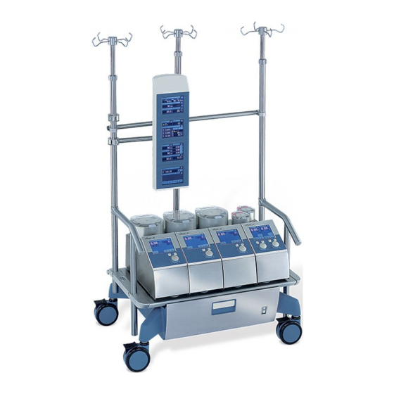
S5 System • System description 3.2.1 Total overview Fig. 1: Overview of S5 System SM-5811-0000.01 ENG... - Page 23 Supports 4 pump housings or units (depending on the type of console) 4 Main switch Switches the entire S5 System on and off 5 S5 mast retaining flange (left / right) Side components for supporting the sliding T-bar handles and telescopic masts 6 Push bar ➜...
- Page 24 S5 System • System description Fig. 2: Overview of S5 mast system extension SM-5811-0000.01 ENG...
- Page 25 ➜ 18 S5 mast system extension for extending the S5 mast system ➜ Can be mounted on both sides of the S5 System on the telescope mast 7 19 S5 telescope mast for mast system extension with 20 Console casters and...
-
Page 26: Overview Of Mast Pump Systems (Optional)
S5 System • System description 3.2.2 Overview of mast pump systems (optional) Fig. 3: Overview of mast pump systems 1 Item name Function 28 S5 mast roller pump system 150 with For details, see chapter 3.2.5 on page 3.12. S5 mast roller pump 150 and... - Page 27 S5 System • System description Fig. 4: Overview of mast pump systems 2 Item name Function 30 S5 mast roller pump system 85 with For details, see chapter 3.2.5 on page 3.12. two S5 mast roller pumps 85 with double holder and...
-
Page 28: Overview Of S5 System Panel
32 Display and control module with Control and configuration of the S5 System 33 Touch screen 34 Mast holder with Positioning the S5 system panel on the mast system of the 35 Fast clamp connector S5 System 36 Clamping lever... -
Page 29: System Panel (Optional)
System panel (optional) Because most of the components are identical in function and construction, the following overview lists only the obvious differences. Fig. 6: Front and back of the S5 system panel (optional) Item Name Function 39 S5 system panel, 3 pos. -
Page 30: Overview Of The Electronic / And Power Pack
S5 System • System description 3.2.4 Overview of the electronic / and power pack Fig. 7: E/P pack Item name Operation 45 System connection panel 46 Circuit breaker F13 Automatic circuit breaker 10 A for the sensor modules 47 Connection for S5 battery discharger... - Page 31 S5 System • System description Item name Operation 57 Socket 7-9 On the right hand side of the E/P pack Connecting pumps and devices (e.g. system panel) 58 Socket 10-12 On the left hand side of the E/P pack Connecting pumps and devices (e.g. system panel)
-
Page 32: Overview Of Pumps And Pump Control Panels
S5 System • System description 3.2.5 Overview of pumps and pump control panels S5 roller pump 150 and S5 double roller pump 85 Fig. 8: Overview of S5 roller pump 150 and S5 double roller pump 85 3.12 SM-5811-0000.01 ENG... - Page 33 S5 System • System description Item name Operation 16 S5 roller pump 150 17 S5 double roller pump 85 68 Pump housing 69 Switch Switching the pump on and off ➜ 70 Control panel with Monitoring and displaying the pump functions and the...
-
Page 34: S5 Mast Roller Pumps
S5 System • System description S5 mast roller pumps Fig. 9: Overview of mast roller pumps 150 and 85 3.14 SM-5811-0000.01 ENG... - Page 35 Overriding the monitoring functions 92 Setting knob Setting the speed 93 Cable CAN/24 V Power supply for the S5 system panel MRP 150/85 and the pump (connection to system slots 1-12) 94 Switch Switching the control panel and the mast roller pump on...
-
Page 36: 3.3 Service-Relevant Assemblies
S5 System • System description 3.3 Service-relevant assemblies Assembly Component contains the following service-relevant assemblies/components: ◗ E/P pack Circuit board Backplane HBP 0321 ◗ Circuit board Battery switch HUS 0318 ◗ Circuit board System boards A HEK 0411 ◗ Circuit board System boards B HEX 0412 ◗... - Page 37 E/P pack Due to its weight, removal of the E/P pack is best done by two persons. Also note that the S5 System features a UPS supplied by two batteries. When you are working on the E/P pack, the danger of short circuits remains as long as the batteries are connected and charged, even though the mains power cable may be disconnected.
-
Page 38: Assembly Overview - E/P Pack
S5 System • System description 3.3.1 Assembly overview – E/P pack Overview of E/P pack A 11 A 10 Fig. 10: Assembly overview – E/P pack (1) 3.18 SM-5811-0000.01 ENG... - Page 39 S5 System • System description Item Name Number Part Number E/P pack 28-98-00 Pump and device slot (front) 97-103-662 (6 sockets) Pump and device slot (right) (3 sockets) AC outlet connection Pump and device slot (left) (3 sockets) Remote control for mains power switch...
- Page 40 S5 System • System description A 12 A 13 A 14 A 15 A 16 A 18 A 17 Fig. 11: Assembly overview – E/P pack (2) Item Name Number Part Number E/P pack 28-98-00 A 12 System AC oulet...
-
Page 41: Overview - Switching Power Supply
S5 System • System description Overview – Switching power supply A 19 A 20 A 21 A 22 A 18 A 23 Fig. 12: Switching power supply Item Name Number Part Number A 18 Switching power supply HLM-NT-S5 96-403-551 A 19... -
Page 42: Assembly Overview - S5 Rp 150
S5 System • System description 3.3.2 Assembly overview – S5 RP 150 B 11 B 12 B 14 B 10 B 13 Fig. 13: Assembly overview – S5 RP 150 3.22 SM-5811-0000.01 ENG... - Page 43 S5 System • System description Item Name Number Part Number S5 roller pump 150 / S5 RP150 10-80-00 10-85-10 Control panel RP150 10-80-10 LCD touch screen 97-103-616 Circuit board keys and LEDs HKD 0327 90-305-640 Computer board HKR 0325 90-305-620...
-
Page 44: Assembly Overview - Drp 85
S5 System • System description 3.3.3 Assembly overview – DRP 85 C 12 C 11 C 13 C 14 C 11 Fig. 14: Assembly overview – DRP 85 3.24 SM-5811-0000.01 ENG... - Page 45 S5 System • System description Item Name Number Part Number S5 double roller pump 85 / S5 DRP85 10-85-00 Control panel DRP85 10-85-50 LCD touch screen 97-103-616 Circuit board keys and LEDs HKD 0327 90-505-640 Computer board HKR 0325 90-305-620...
-
Page 46: Assembly Overview - System Panel
S5 System • System description 3.3.4 Assembly overview – System panel System panel (4 pos.) D 10 Fig. 15: Assembly overview – System panel (4 pos.) Item Name Number Part Number S5 system panel, 4 pos. 28-95-00 Backplane system panel... -
Page 47: System Panel (3 Pos. And 6 Pos.)
Note: The S5 system panel (6 pos.) is made up of two S5 system panels (3 pos.). As the functions performed by these S5 system panels are identical, we are using the S5 system panel (3 pos.) for the overview. There are differences in the holder. - Page 48 S5 System • System description System panel (5 pos.) D 13 D 14 D 10 Fig. 17: Assembly overview – System panel (5 pos.) Item Name Number Part Number D 13 S5 system panel, 5 pos. 28-95-01 Backplane system panel (identical to 4pos.)
-
Page 49: Assembly Overview - Sensor Modules
S5 System • System description 3.3.5 Assembly overview – Sensor modules E 10 E 11 Fig. 18: Assembly overview – Sensor modules SM-5811-0000.01 ENG 3.29... - Page 50 S5 System • System description Item Name Number Part Number S5 mains power connection module 29-12-30 S5 UPS module 28-98-80 Circuit board UPS charging device HUL 0319 90-305-560 Circuit board UPS control HUK 0320 90-305-570 S5 DC/DC module 28-98-20 Circuit board DC/DC...
-
Page 51: Assembly Overview - S5 Mrp 150
S5 System • System description 3.3.6 Assembly overview – S5 MRP 150 Fig. 19: Assembly overview S5 MRP 150 Item Name Number Part Number S5 MRP 150 (complete) 10-81-00 Holder MRP 150 10-88-69 Pump head MRP150 (complete) 10-81-00 Pump cover MRP150 (complete) -
Page 52: Assembly Overview - S5 Mrp 85/1 And S5 Mrp 85/2
S5 System • System description 3.3.7 Assembly overview – S5 MRP 85/1 and S5 MRP 85/2 Fig. 20: Assembly overview – S5 MRP 85/1 and S5 MRP 85/2 Item Name Number Part Number S5 MRP 85/1 and S5 MRP 85/2 (identical construction) -
Page 53: Assembly Overview - Control Panels For Mast Roller Pumps
S5 System • System description 3.3.8 Assembly overview – Control panels for mast roller pumps H 11 H 10 H 12 H 14 H 13 H 15 Fig. 21: Assembly overview Control panels for mast roller pumps Item Name Number... - Page 54 S5 System • System description Socket connection mast roller pump Connetion cable 97-103-625 H 10 Line filter H 11 Switch H 12 Speaker 97-103-669 H 13 Shaft encoder with H 14 setting knob H 15 3.34 SM-5811-0000.01 ENG...
-
Page 55: Assembly Overview Scp System For S5
S5 System • System description 3.3.9 Assembly overview SCP System for S5 All SCP Systems must only be connected to the S5 System by an appropriate (fixed) cable: Additional device (part number) Connection with SCP System (60-00-00) SCP System (only for S5 System) -
Page 56: 3.3.10 Overview - Circuit Boards
S5 System • System description 3.3.10 Overview – Circuit boards Overview Backplane E/N-Block A 26 A 27 A 28 A 33 A 30 A 34 A 17 A 29 A 25 A 24 A 31 A 32 A 35 Fig. 22: Circuit board Backplane E/N-Block 3.36... - Page 57 S5 System • System description Item Name Number Part Number A 17 Backplane (complete) HBP 0321 90-305-580 A 24 Block for connection of DC/DC module CON 1 96-215-125 A 25 Plug connection speaker CON 2 96-201-015 A 26 Connection system slots (left)
- Page 58 S5 System • System description Circuit board battery switch A 37 A 36 A 39 A 38 A 44 A 45 A 42 A 46 A 48 A 43 A 47 A 40 A 49 A 41 A 50 Fig. 23: Circuit board battery switch...
- Page 59 S5 System • System description A 47 Screwed terminal battery (+ terminal) with socket head screw DIN 912 M5x8 71-115-025 washer DIN 127 5.3 71-120-528 A 48 Screwed terminal power supply (– terminal) with socket head screw DIN 912 M5x8 71-115-025 washer DIN 127 5.3...
-
Page 60: Circuit Board Motor Controller
S5 System • System description Circuit board motor controller B 14 B 22 B 20 B 21 B 17 B 18 B 19 B 15 B 16 B 23 Fig. 24: Circuit board motor controller Item Name Number Part Number... -
Page 61: Circuit Board Motor Power Amplifier
S5 System • System description Circuit board motor power amplifier B 13 B 24 B 27 B 26 B 25 Fig. 25: Circuit board motor power amplifier Item Name Number Part Number B 13 Circuit board motor power amplifier HMF 0408... -
Page 62: Circuit Board Computer Board
S5 System • System description Circuit board computer board B 39 B 38 B 31 B 37 B 30 B 36 B 35 B 34 B 33 B 32 B 29 B 28 Fig. 26: Circuit board computer board Item... -
Page 63: Circuit Board Inverter (Pumps)
S5 System • System description Circuit board inverter (pumps) B 40 B 41 B 42 Fig. 27: Circuit board inverter Item Name Number Part Number B 40 Circuit board inverter LXM1617-05-6x 93-146-026 B 41 Socket for connection circuit board CON INV... -
Page 64: Circuit Board Keys And Leds
S5 System • System description Circuit board keys and LEDs B 43 B 44 B 47 B 45 B 46 B 46 B 47 Fig. 28: Circuit board keys and LED Item Name Number Part Number B 43 Circuit board keys and LEDs for RP 150 and MRP 85/1... -
Page 65: Overview Backplane System Panel (4 Pos. And 5 Pos.)
S5 System • System description Overview backplane system panel (4 pos. and 5 pos.) D 18 D 17 D 16 D 21 D 19 D 15 D 20 D 22 D 14 D 23 Fig. 29: Circuit board backplane system panel (4 pos. and 5 pos.) SM-5811-0000.01 ENG... - Page 66 S5 System • System description Item Name Number Part Number Backplane system panel HDB 0406 90-305-740 D 15 Plug connection speaker CON 9 96-201-015 D 16 Plug connection S5 System (CAN) CON 6 96-201-098 D 17 Plug connection line filter...
-
Page 67: Overview Backplane System Panel (3 Pos. And 6 Pos.)
S5 System • System description Overview backplane system panel (3 pos. and 6 pos.) D 18 D 12 D 16 D 15 D 19 D 17 D 20 Fig. 30: Backplane system panel (3 pos. and 6 pos.) Item Name... -
Page 68: Overview Circuit Board Display And Control Module
S5 System • System description Overview circuit board display and control module D 24 D 10 D 25 D 28 D 26 D 27 Fig. 31: Circuit board display and control module Item Name Number Part Number D 10 Circuit board display and control module... -
Page 69: Circuit Board Inverter (System-Panel And Control Panel)
S5 System • System description Circuit board inverter (system-panel and control panel) D 29 D 31 D 30 Fig. 32: Circuit board inverter Item Name Number Part Number D 29 Circuit board inverter LXM1617-05-6x 93-146-026 D 30 Socket for connection circuit board... -
Page 70: Circuit Board Fan Control (Control Panel Mast Roller Pumps)
S5 System • System description Circuit board fan control (control panel mast roller pumps) H 17 H 16 Fig. 33: Circuit board fan control Item Name Number Part Number Circuit board Fan control HDM 0503 90-105-850 H 16 Socket connection fan... -
Page 71: Circuit Board Mast Roller Pumps 85 (Motor Controller And Motor Power Amplifier)
S5 System • System description Circuit board mast roller pumps 85 (motor controller and motor power amplifier) G 11 G 10 G 12 G 13 G 16 G 15 G 14 Fig. 34: Circuit board motor controller MRP85 Item Name... - Page 72 S5 System • System description G 18 G 20 G 19 G 17 Fig. 35: Circuit board motor power amplifier MRP85 Item Name Number Part Number Circuit board motor power amplifier MRP85 HME 0402 90-305-700 G 17 Socket connection pump head...
-
Page 73: Brief Overview System Panel
Brief overview system panel Key icons and display (brief overview) Detailed information on the operation of the S5 System can be found in the associated Operating Instructions. For ease of navigation, the following pages give you a brief overview of the system menu:... - Page 74 S5 System • Brief overview system panel Status display OK Display green (Display for the time being only applies to bubble activity) – Bubble sensor connected – No bubbles Key icon Clear alarm – Clears the alarm indicated in the System menu, after the cause of the alarm has been eliminated.
-
Page 75: Key Icons And Displays Of The System Menu
S5 System • Brief overview system panel Key icons and displays of the system menu 20.05.2005 14:15:01 Level Arterial Pump (1) stopped Temperature was above max. limit Scroll Fig. 36: System menu displet Item Name Function a Icon System menu Display of the selected menu name, date and time. - Page 76 S5 System • Brief overview system panel e Display Battery status Bar graph of the battery charge status – Battery test required or fault in the battery – Batteries are fully charged (bar graph with long arrow) – During trickle charging (bar graph with short arrow) –...
-
Page 77: Fault Messages And Troubleshooting
S5 System • Fault messages and troubleshooting Fault messages and troubleshooting The S5 system undergoes continuous self-monitoring. Faults that occur (e.g. the failure of a component) are displayed in the system menu. Fault messages 5.1.1 Unspecified faults Note: Even if –... -
Page 78: Fault Messages
S5 System • Fault messages and troubleshooting 5.1.2 Fault messages The following applies with regard to all displayed fault messages: ◗ Check mains power cable connection ◗ Check (and where necessary clean) connector of the relevant or displayed components. ◗... - Page 79 S5 System • Fault messages and troubleshooting The pump speed can no longer be adjusted correctly. Shaft angle encoder fault Pump 1 ➜ Shaft encoder defective ➜ Fault in motor controller Fault in circuit board Computer board (HKR 0325) Pump 1 ➜...
- Page 80 S5 System • Fault messages and troubleshooting LED display on pump control panel remains dark. Speed knob LED failure Pump 1 ➜ Connections to circuit board keys and LEDs (HKD 0327) interrupted ➜ Fault in circuit board HKD 0327 ➜...
-
Page 81: Battery Fault
S5 System • Fault messages and troubleshooting Battery fault Display in system menu Description ➜ possible cause/effect ◗ Steps to be taken (please proceed in the order listed) Battery is a high-drain battery. Charging time too long The battery charge time was exceeded (internal charge time The residual charging time was too long limit approx. - Page 82 S5 System • Fault messages and troubleshooting Other messages: The charge process was interrupted: ➜ Fault in battery Battery defective; charging has stopped ➜ Additional battery status display ➜ Battery is defective ◗ Replace battery (-ies) 2 Current sensors connected in series to identify increases in current: ➜...
-
Page 83: Faults In The Sensor Modules Or Sensors
S5 System • Fault messages and troubleshooting Faults in the sensor modules or sensors Display in system menu Description ➜ possible cause/effect ◗ Steps to be taken ➜ There is a module or sensor defect. (The display of the Module defective relevant icon indicates the corresponding monitoring function. -
Page 84: 5.2 Operating The Additional Devices For The S5 System
– the electrical remote-controlled tubing clamp to the S5 System. For information about the relevant alarm messages, see the S5 System operating instructions. If an alarm is not cleared or other errors and faults are displayed, please refer to the separate operating instructions or service manual for additional measures. -
Page 85: Replacing Components
S5 System • Replacing components Replacing components Please note that it is essential that ESD protective safety measures are taken when working with components susceptible to ESD. When removing or fitting circuit boards or components susceptible to ESD, ensure that you use ESD mats, wrist straps, or similar. - Page 86 S5 System • Replacing components Fig. 38: Removing the E/P pack (2) ◗ Pull the E/P pack out of the console far enough to allow you to straighten out the two handles on the side of the pack. ◗ Now pull the E/P pack out of the console completely. Warning: Due to its weight, removal of the E/P pack is best done by two persons.
-
Page 87: Opening The E/P Pack
Opening the E/P pack Note that the S5 System features a UPS supplied by two batteries. When you are working on the E/P pack, the danger of short circuits remains as long as the batteries are connected and charged, even though the mains power cable may be disconnected. - Page 88 S5 System • Replacing components Fig. 40: Opening the E/P pack (2) The rear panel of the E/P pack must also be removed in order to access other components easily: ◗ Loosen the six socket head screws shown (DIN 912 M4x8 / allen key size 3 mm).
-
Page 89: Removing The System Boards
S5 System • Replacing components Removing the system boards Fig. 41: Removing the system boards To remove the system boards: ◗ Loosen both screws. ◗ Pull the system boards out by the handle. The system boards (HEK 0411 and HEX 0412) can only be replaced as a complete unit. -
Page 90: Removing The Switching Power Supply
S5 System • Replacing components Removing the switching power supply A 51 A 40 A 43 A 52 A 53 Fig. 42: Removing the switching power supply (1) In order to remove the switching power supply: ◗ Loosen the allen fasteners (DIN 912 M4x10 / allen key size 4 mm) of the A 40 (red) and A 43 (black) connections on the battery switch circuit board A 6. - Page 91 S5 System • Replacing components Connection A 43 (black/– Pol/24VDC_L ) 97-101-923 (cable with socket head screw DIN 912 M5x8 harness complete) washer DIN 127 5.3 Fig. 43: Removing the switching power supply (2) ◗ Carefully turn the E/P pack over.
-
Page 92: Replacing The Batteries
S5 System • Replacing components Replacing the batteries The S5 System has an integrated test routine for the batteries (see the Operating Instructions). When the batteries no longer deliver the required power values or are defect, they must be replaced immediately (in order to ensure that the UPS functions properly). -
Page 93: Replacing The Battery Switch Circuit Board
S5 System • Replacing components Replacing the battery switch circuit board A 31 A 34 A 33 A 32 Fig. 45: Replacing the battery switch circuit board In the interest of clarity, the cables have been omitted from the diagram. -
Page 94: Replacing Fuses (Circuit Board Battery Switch)
Fuse 3.15 A slow 93-510-044 A 38 Fuse 10 A slow 93-511-030 A 39 Fuse 1 A slow 93-510-039 Replace fuses only with fuses of the same type and specification! Otherwise the S5 System may be damaged. 6.10 SM-5811-0000.01 ENG... -
Page 95: 6.2 Pumps
S5 System • Replacing components 6.2 Pumps As the pumps of the S5 System are of identical construction to some degree, we have illustrated the following descriptions with only one figure in some cases. Unless otherwise specified, the procedure for the installation of the pumps is identical. - Page 96 S5 System • Replacing components Fig. 48: Lifting open the housing ◗ Carefully lift open the housing base plate. Warning: The housing base plate cannot be removed completely, because the connection between fan and circuit board must be disconnected first! 6.12...
- Page 97 S5 System • Replacing components Fig. 49: Disconnecting the retaining ring (1) ◗ Using appropriate retaining ring pliers (shaft diameter 3.2 mm or 1/8"), pry the two open ends of the retaining ring far enough apart to allow you to pull the ring off. As the ring is under high spring tension, it is recommended to work as a team of two persons in this case, too.
- Page 98 S5 System • Replacing components B 51 B 50 B 49 B 53 B 52 B 48 B 14 B 13 Fig. 50: Disconnecting the retaining ring (2) and dismantling the pump head ◗ Disconnect the connector B 48 and the following connectors from the circuit board B 13 (Motor power...
- Page 99 S5 System • Replacing components B 13 B 14 Fig. 51: Removal of circuit boards (here DRP 85) ◗ Pull the bracket with the two circuit boards B 13 and B 14 out of the pump housing. SM-5811-0000.01 ENG 6.15...
- Page 100 S5 System • Replacing components B 13 B 22 B 14 Fig. 52: Disassembly of circuit boards For further disassembly of the RP 85: ◗ Disconnect the connector B 22 from the circuit board Motor power amplifier B 13. ◗...
- Page 101 S5 System • Replacing components No further dismantling of the double roller pump is planned. Each of the three units – Motor controller circuit board, – Motor power amplifier circuit board and – Pump head (10-86-00) is to be replaced as a complete unit.
-
Page 102: Removal Of Roller Pump 150
S5 System • Replacing components Removal of roller pump 150 B 13 B 22 B 14 B 48 Fig. 53: Removing the circuit board (1) 6.18 SM-5811-0000.01 ENG... - Page 103 S5 System • Replacing components For further disassembly of the RP 150: ◗ If it has not already been done: Remove the pump cover from the pump head. ◗ Carefully place the pump head down on a soft, flat work surface. Take care not to scratch the pump head.
-
Page 104: Removal Of The Pump Control Panel And Touch Screen
S5 System • Replacing components 6.2.2 Removal of the pump control panel and touch screen Fig. 54: Removing the pump control panel and touch screen (1) ◗ Disassemble the base plate as described above. ◗ Loosen all connectors. Always mark the plugs and cables to avoid mistakes in subsequent assembly. If necessary, make a note of the cable connection positions. - Page 105 S5 System • Replacing components Fig. 55: Removing the pump control panel and touch screen (2) ◗ Loosen the six socket head screws (DIN 912 M3x10 / allen key size 2.5 mm) including the washers (DIN 9021 3.2) and the spring washers (DIN 127 B3).
- Page 106 S5 System • Replacing components Removal of the CPU B 4 circuit board is necessary in the following cases: – To replace this circuit board – In order to gain access to the Inverter B 39 circuit board and keys and LEDs B 42 located underneath –...
- Page 107 S5 System • Replacing components B 46 Fig. 57: Removing the display and control module (2) ◗ Loosen the four distance bolts (internal/external thread M3 x 15) from the circuit board B 4. ◗ Take care to lift the circuit board straight upwards to avoid bending the contact pins B 46.
- Page 108 S5 System • Replacing components B 41 B 38 Fig. 58: Removing the display and control module (3) To remove the Inverter B 38 circuit board: ◗ Loosen the two self-locking nuts (DIN 985 M3 WAF 5.5) from the cover.
- Page 109 S5 System • Replacing components B 41 B 42 Fig. 59: Removing the display and control module (4) To remove the display carrier and the Keys and LEDs B 42 circuit board: ◗ Loosen the PT screws (PT Z30x8 WN 5411 and socket head screw DIN 912 M3x6) from the Display carrier.
-
Page 110: Removing The Shaft Encoder
S5 System • Replacing components Removing the shaft encoder B 54 B 56 B 55 B 59 B 57 B 58 B 55 B 54 Fig. 60: Removal of the circuit board with the shaft encoder 6.26 SM-5811-0000.01 ENG... - Page 111 S5 System • Replacing components Item Name Number Part Number B 54 Shaft encoder with cable harness 97-103-608 B 55 S5 setting knob 10-85-14 B 56 Rubber ring 10-85-14 B 57 Threaded rod, DIN 916 M4x6 71-118-317 B 58 Washer PA 6,2 x 12,0 x 0,5...
-
Page 112: Replacing The Line Filter On The Pumps
S5 System • Replacing components 6.2.3 Replacing the line filter on the pumps When removing the line filter, the housing base plate must be removed first (see Page 6.11). Fig. 61: Removing the line filter ◗ Loosen the two nuts (DIN 934 M3 WAF 5.5 mm) on the line filter including the spring washers (DIN 127, B 3). -
Page 113: 6.3 Mast Roller Pump Mrp150
S5 System • Replacing components 6.3 Mast roller pump MRP150 6.3.1 Opening the pump housing F 12 F 10 F 11 Fig. 62: Removing the base plate ◗ If necessary, remove the pump cover F 3. ◗ Carefully lay the pump on its side. - Page 114 S5 System • Replacing components Fig. 63: Removing the housing (1) ◗ Remove hexagon screw a including washers b and c. ◗ Remove connector piece d with fast clamp connector F 1. Assembly material a Hexagon screw (DIN 933 M6x16, AF 10 mm) b Washer (DIN 125 A 3.2)
- Page 115 S5 System • Replacing components Fig. 64: Removing the housing (2) ◗ Rotate the holder a and housing b so you can loosen the indicated head socket screws through opening c. ◗ Gradually loosen the four head socket screws (DIN 912 M4x8 / allen key size xx mm).
-
Page 116: Removing The Mast Roller Pump Mrp 150
S5 System • Replacing components 6.3.2 Removing the mast roller pump MRP 150 For further disassembly of the MRP 150, proceed as described in section „Removal of roller pump 150“ on page 6.18. When reassembling (in reverse order) thereafter be extremely careful in positioning the individual components. -
Page 117: 6.4 Mast Roller Pump Mrp85/X
S5 System • Replacing components 6.4 Mast roller pump MRP85/x 6.4.1 Removing the double holder Fig. 65: Removing the double holder ◗ Remove cap a from the back of the double holder G 1. ◗ Remove the four head socket screws (DIN 912 M4x8 / allen key size xx mm). -
Page 118: Opening The Pump Housing
S5 System • Replacing components 6.4.2 Opening the pump housing Fig. 66: Opening the pump housing ◗ If necessary, remove the pump cover. ◗ Remove the indicated head socket screws (DIN 912 M3x6 / allen key size 2.5 mm) (on base plate). -
Page 119: Replacing Circuit Boards
S5 System • Replacing components 6.4.3 Replacing circuit boards G 19 Fig. 67: Replacing the circuit board HMR 0403 (1) ◗ Remove the three head socket screws shown above (DIN 912 M3x6 / allen key size 2.5 mm), including washers (DIN 125 A 3.2). - Page 120 S5 System • Replacing components G 14 G 15 G 13 G 14 G 12 Fig. 68: Replacing the circuit board HMR 0403 (2) ◗ Lift up the circuit board Motor controller MRP85 G 5. ◗ Disconnect the following connectors from the circuit board G 5:...
- Page 121 S5 System • Replacing components Fig. 69: Replacing the circuit board HME 0402 (1) ◗ Remove both cap nuts a (DIN 1587 M4) on heat sink b to replace the circuit board Motor power amplifier MRP85 G 6. SM-5811-0000.01 ENG...
- Page 122 S5 System • Replacing components Fig. 70: Replacing the circuit board HME 0402 (2) ◗ Rotate the pump. ◗ Remove the two head socket screws shown above (DIN 912 M3x6 / allen key size 2.5 mm), including washers (DIN 125 A 3.2).
- Page 123 S5 System • Replacing components G 20 G 18 G 17 Fig. 71: Replacing the circuit board HME 0402 (3) ◗ Lift up the circuit board motor power amplifier MRP85 G 6 circuit board. ◗ Disconnect the following connectors from the circuit board G 6:...
-
Page 124: Removing The Pump Head
S5 System • Replacing components 6.4.4 Removing the pump head Fig. 72: Disconnecting the retaining ring ◗ Using appropriate retaining ring pliers (shaft diameter 3.2 mm or 1/8"), pry the two open ends of the retaining ring far enough apart to allow you to pull the ring off. As the ring is under high spring tension, it is recommended to work as a team of two persons in this case, too. - Page 125 S5 System • Replacing components Fig. 73: Removing the pump head ◗ Pull the pump head out of the housing. No further dismantling of the pump head RP85 is planned. The pump head (10-86-00) is replaced as a complete unit.
-
Page 126: 6.5 System Panel
S5 System • Replacing components 6.5 System Panel As most of the S5 system panels are of identical construction, we have illustrated the following descriptions with only one figure in some cases. Unless otherwise specified, the procedure for the installation of the system panels is identical. In the interest of clarity, cables and connectors have been omitted in some of the figures. - Page 127 S5 System • Replacing components Fig. 75: Open the system panel (1) ◗ Loosen the eight socket head screws (DIN 912 M3x10 / allen key size 2.5 mm) including the washers (DIN 125 A 3.2). Fig. 76: Open the system panel (2) ◗...
- Page 128 S5 System • Replacing components Fig. 77: Open the system panel (3) ◗ Carefully open up the rear of the housing. Warning: The rear of the housing cannot be fully opened up completely, because the connections between the rear of the housing an the circuit board backplane must be disconnected first! 6.44...
- Page 129 Fig. 78: Open the system panel (4) ◗ Loosen the connectors – Connection speaker D 10 – Connection S5 System (CAN) D 11 – Connection line filter D 12 – Connection fans D 13 and D 14 ◗ Open up the rear of the housing completely.
-
Page 130: Replacing The Circuit Board Backplane
S5 System • Replacing components 6.5.2 Replacing the circuit board backplane Fig. 79: Removing the circuit board backplane ◗ Loosen the eight socket head screws (DIN 912 M3x6 / allen key size 2.5 mm). ◗ Remove the circuit board Backplane system panel D 1. -
Page 131: Replacing Components Of The Display And Control Module
S5 System • Replacing components 6.5.3 Replacing components of the display and control module Abb. 80: Open the housing ◗ Loosen the four PT screws (KB 30x10 WN 1411) and carefully lift the rear of the housing up. D 17... -
Page 132: Replacing The Display And Control Module
S5 System • Replacing components Replacing the display and control module Abb. 82: Replacing the circuit board display and control module ◗ In order to separate the circuit board display and control module D 10 of the frame, loosen the four socket head screws (DIN 912 M3x6 / allen key size 2.5 mm). -
Page 133: Replacing The Circuit Board Inverter
S5 System • Replacing components Replacing the circuit board Inverter D 31 D 29 Abb. 83: Replacing the circuit board Inverter To remove the circuit board Inverter D 21: ◗ Loosen the two self-locking nuts (DIN 985 M3 WAF 5.5) from the cover. -
Page 134: Replacing The Touch Screen
S5 System • Replacing components Replacing the touch screen D 31 Fig. 84: Replacing the touchscreen To remove the display carrier and the touchscreen: ◗ Loosen the socket head screws (DIN 912 M3x6 / allen key size 2.5 mm) and the PT screws (KB 30x10 WN 1411) from the Display carrier. -
Page 135: 6.6 Control Panels For Mast Roller Pumps
S5 System • Replacing components 6.6 Control panels for mast roller pumps As the control panels are of identical construction to some degree, we have illustrated the following descriptions with only one figure in some cases. Unless otherwise specified, the procedure for the installation of the control panels is identical. - Page 136 S5 System • Replacing components H 18 H 19 H 12 H 20 Fig. 86: Opening the control panel (2) ◗ Disconnect the following connectors from the circuit board computer board H 4 : Item Name Number Part number H 18...
-
Page 137: Replacing Control Panel Components
S5 System • Replacing components 6.6.2 Replacing control panel components Replacing the circuit board fan control H 21 H 15 H 18 Fig. 87: Replacing the circuit board fan control ◗ Disconnect the following connectors from the circuit board fan control H 6:... -
Page 138: Replacing Circuit Boards
S5 System • Replacing components Replacing circuit boards Removal of the circuit board computer board H 4 is necessary in the following cases: – To replace this circuit board – In order to gain access to the inverter H 7 circuit board and keys and LEDs H 5 located underneath it –... - Page 139 S5 System • Replacing components Fig. 89: Disconnecting the control panel (2) ◗ Remove the four distance bolts (internal/external thread M3x12 (AF 5.5 mm) from the circuit board H 4. ◗ Take care to lift the circuit board straight upwards to avoid bending the contact pins a.
- Page 140 S5 System • Replacing components H 24 Fig. 90: Disconnecting the control panel (3) To remove the circuit board inverter H 7: ◗ Detach both self-locking nuts (DIN 985 M3 AF 5.5) from the cover. ◗ Loosen the connection LCD B 42 and lift the circuit board up.
-
Page 141: Replacing The Touch Screen
S5 System • Replacing components Replacing the touch screen Fig. 91: Replacing the touch screen To remove the display carrier and the keys and LEDs H 5 circuit board: ◗ Remove the PT screws (PT Z30x8 WN5411) and head socket screws (DIN 912 M3x6) from the display carrier. -
Page 142: Removing The Shaft Encoder
S5 System • Replacing components Removing the shaft encoder H 13 H 27 H 26 H 30 H 28 H 29 H 26 H 13 Fig. 92: Removing of the circuit board with the shaft encoder 6.58 SM-5811-0000.01 ENG... - Page 143 S5 System • Replacing components Item Name Number Part number H 13 Shaft encoder with cable harness 97-103-608 (identical to shaft encoder on pumps) H 26 S5 setting knob 10-85-14 H 27 Rubber ring 75-521-529 H 28 Grub screw DIN 916 M4x6...
-
Page 144: 6.7 Replacing Circuit Boards/Sensor Modules
S5 System • Replacing components 6.7 Replacing circuit boards/sensor modules As the exterior design of the sensor modules is virtually identical, we have only used one figure of the interface module in following description. In the interest of clarity, cables and connectors have been omitted. - Page 145 S5 System • Replacing components Fig. 94: Replacing sensor boards (2) ◗ Detach the cover a. ◗ Loosen all connectors between the back of the front plate b and the sensor board c. ◗ Remove both screws on the sensor board.
-
Page 146: 6.8 Connectors
S5 System • Replacing components 6.8 Connectors When inserting the new cable ensure that the connections are correctly assigned. For overview the most important connectors with pin assignment. Further information to the part numbers is provided in the chapter 7.5 „Service component part numbers“ on page 7.16. -
Page 147: Circuit Boards Connectors
S5 System • Replacing components 6.8.2 Circuit boards connectors Phoenix plug and socket Fig. 97: Phoenix plug (e.g. connecting power supply of the pumps(internal)) FCI plug and socket Fig. 98: FCI plug (e.g. CAN (internal) or diverse pump connections (internal)) SM-5811-0000.01 ENG... -
Page 148: Molex Plug And Socket
S5 System • Replacing components Molex plug and socket 4 3 2 1 Fig. 99: Molex plug (e.g. connecting Hall sensors, fans etc.) AMP plug and socket Fig. 100: AMP plug (e.g. connecting speaker system panel and pumps) 6.64 SM-5811-0000.01 ENG... -
Page 149: Appendix
S5 System • Appendix Appendix S5 system specifications 7.1.1 Dimensions, weights, operating conditions Console Height (to the surface of the pump cover) 640 mm Depth 600 mm Width (incl. push bars) 3 position 745 mm 4 position 890 mm 5 position... -
Page 150: Masts
S5 System • Appendix Masts Telescope masts Height (from the floor) in the lowest configuration 1230 mm min. 1840 mm max. in the highest configuration 1520 mm min. 2120 mm max. Diameter (fixed part) Ø 33 mm Movable mast Height (from the floor) 1520 mm min. -
Page 151: Pumps
S5 System • Appendix Pumps Roller pump 150 Height 285 mm Width 180 mm Depth 485 mm Weight 15 kg Double roller pump 85 Height 257 mm Width 180 mm Depth 485 mm Weight 12 kg Mast roller pump 150... -
Page 152: System Panel
S5 System • Appendix System panel for 3 display and control modules Height 475 mm Width 184 mm Depth (without mast holder) 94 mm Weight (without display and control module) 3.9 kg for 4 display and control modules Height 590 mm... -
Page 153: Electrical Specifications
S5 System • Appendix 7.1.2 Electrical Specifications Device protection Protection class 1 Type B Drip-proof IPX1 Electronics and power pack Input voltages 100 V~ to 240 V~; 50 / 60 Hz Permissible mains voltage fluctuation ± 10% Maximum power consumption (standard equipment) -
Page 154: Shelf With Ac Outlet
S5 System • Appendix Shelf with AC outlet 3/4/5 position Weight - shelf approx. 6.5 kg Maximum load - shelf 8 kg Number of sockets Protection at 230/240 V: Circuit breaker 2 A Protection at 110/115 V: Circuit breaker 2 A... -
Page 155: Modules And Sensors
S5 System • Appendix Pulse Mode Control for SCP/S5 Pulse frequency 40 to 80 beats per minute (adjustable in increments of 5) Pulse flow percentage 50% (not adjustable) Minimum pulse duration M 300 ms Base flow percentage 50% (not adjustable) - Page 156 7 bit Parity (fixed) none Stop bits (fixed) Time grid (fixed) 10 seconds (interval of the data sent by the S5 System) Interface, galvanically isolated: Isolation voltage 1.5 kV Serial interface cable: 1 x D-SUB 9f 1 x ODU MEDI-SNAP...
-
Page 157: Pumps
S5 System • Appendix 7.1.3 Pumps Pump specifications Roller pump Double roller pump Diameter of pump raceway 150 mm 85 mm Diameter of occlusion roller 30.5 mm 15 mm Speed range 0 to 250 rpm (clockwise, counterclockwise) Deviation in speed accuracy ±1% of the terminal value 250 rpm plus ±0.5% of set value... - Page 158 S5 System • Appendix Pulse mode control specifications Pulse frequency setting range 30 to 150 bpm Pulse width setting range 30 to 80% Base flow setting range 30 to 100% rpm deviation < 5 % (while changing from pulse to continuous...
-
Page 159: 7.2 Labelling
IPX1 Drip-proof Icons on the console, pump housing, system panel and control panel: – on the console: Switch S5 System on/off – on the pump housing: Switch the pump on/off – on the system-panel: Switch the system panel on/off – on the control panels: Switching the control panels and... - Page 160 S5 System • Appendix Icons on the S5 power supply module: Potential equalisation point Icons on the system connection panel: Automatic circuit breaker 10 A Icons on the discharger: F10A S Fuse 10 A slow in accordance with DIN 41662 7.12...
-
Page 161: Partnumbers, Standard Components And Accessories
S5 System • Appendix Partnumbers, standard components and accessories 7.3.1 S5 System Consoles with E/P pack and standard mast system S5 console 3 position 48-30-00 4 position 48-40-00 5 position 48-50-00 S5 console table 48-30-30 3 position 4 position 48-40-30... - Page 162 S5 System components S5 System panel 4 position for 4 display and control modules 28-95-00 S5 System panel 3 position for 3 display and control modules (optional) 28-95-03 S5 System panel 5 position for 5 display and control modules (optional)
- Page 163 S5 System • Appendix Pump accessories Pump cover for roller pump RP 150 10-81-75 Pump cover for roller pump DRP 85 10-86-45 2 direction rotation arrows 76-012-001 RP 150 Variolock tubing clamp 10-81-30 Variolock tubing clamp inserts 1/4" x 1/16"...
- Page 164 S5 System • Appendix Tubing clamp inserts Cardioplegia RP 150 3/16" x 1/16" light grey 10-64-70 3/16" x 1/16" 1/4" x 1/16" light brown 10-64-71 1/4" x 1/16" 3/16" x 1/16" white 10-64-72 1/8" x 1/16" 1/4" x 1/16" light blue 10-64-74 3/16"...
-
Page 165: System Accessories
S5 System • Appendix 7.3.2 System accessories Sensors and accessories Medex transducer (MX 960) 45-04-03 Cable for Medex transducer 45-04-15 Holder for one Medex transducer 45-04-16 Holder for 2 Medex transducers 45-04-17 Holder with fast clamp connector for 2 Bentley Trantec transducers... - Page 166 S5 System • Appendix Shelf without AC outlet 3 position 48-31-10 4 position 48-41-10 5 position 48-51-10 Shelf with AC outlet 3 position 48-31-11 4 position 48-41-11 5 position 48-51-11 Cable holder for masts with Ø 33 mm 6 clips 45-09-10 Cable holder for masts with Ø...
- Page 167 S5 System • Appendix S5 mast system extension 50-45-00 consists of: 50-45-05 Swivel telescope mast with infusion rack and castor 2 swivel arms 50-45-10 Vertical mast (including 2 horizontal masts) 50-45-15 Transport locking arm 50-45-20 S5 mast roller pump system 150...
-
Page 168: Additional Devices And Accessories
Remote controller for patient circuit (software) 16-35-10 Remote controller for cardioplegia circuit (software) 16-35-20 45-12-01 Cable for connection to the S5 System (including blocking ferrite) Gas blender system (10 l/min) 25-28-67 Cable for connection to the S5 System (including blocking ferrite) 45-12-02... - Page 169 Electrical remote-controlled tubing clamp (for installation on mast) 60-05-00 consists of: Tubing clamp Swivel arm with fast clamp connector 500 mm Cable for connection to the S5 System (including blocking ferrite) 45-12-00 Electrical remote-controlled tubing clamp (for installation on mast) 60-05-40 consists of: Tubing clamp...
-
Page 170: Disposables And Accessories
The compatibility of disposables and accessories (as stated in the European Directive 93/42 EEC, Appendix 9.1/Basic Requirements) with the S5 System must be verified and guaranteed by the manufacturer concerned. All safety checks and operational checks must be carried out in accordance with the operating instructions supplied with the equipment concerned. -
Page 171: Service Component Part Numbers
S5 System • Appendix Service component part numbers These part numbers concern assemblies and components that are intended solely for use by service technicians. The position number references relate to the illustration of the components in Chapter 3. 7.5.1 S5 System separate components... -
Page 172: Assembly Rp 150
S5 System • Appendix Assembly RP 150 Item Name Number Part Number S5 roller pump 150 / S5 RP150 10-80-00 Control panel RP150 10-80-10 S5 rotary knob 10-80-14 Rotary ring 75-521-529 Threaded rod, DIN 916, M4x6 71-118-317 Nut for panel... - Page 173 S5 System • Appendix Pump head pawl Pawl maxi S5 10-81-40 Pawl spring maxi S5 10-81-41 Retaining ring maxi 10-81-42 Socket head screw, DIN 912, M3x8 71-115-007 Socket head screw, DIN 912, M4x8 71-115-011 Socket head screw, DIN 912, M3x6...
- Page 174 S5 System • Appendix Assembly DRP 85 Item Name Number Part Number S5 double roller pump 85 / S5 DRP85 10-85-00 Control panel DRP85 10-85-50 S5 rotary knob 10-80-14 Rotary ring 75-521-529 Threaded rod, DIN 916, M4x6 71-118-317 Nut for panel...
-
Page 175: Assembly System Panel
90-305-760 C 14 Motor controller HMS 0409 90-305-770 Assembly System panel Item Name Number Part Number S5 system panel, 3 pos. 28-95-03 Backplane board HDT 0501 90-305-830 S5 system panel, 4 pos. 28-95-00 Backplane board HDB 0406 90-305-740 S5 system panel, 5 pos. - Page 176 S5 System • Appendix S5 system panel, 6 pos. 28-95-04 Backplane board (left) HDT 0501 90-305-830 Backplane board (right) HDT 0501 90-505-830 Holder for system panel 6 pos. 28-95-26 Connector 28-95-24 Clamping lever (for double holder) GN604.1-M8-32 73-200-012 Connection cable E/P pack S5 panel 97-103-625 Mast joint holder (complete for 3 pos., 4pos.
-
Page 177: Assembly Sensor Modules
S5 System • Appendix Assembly Sensor modules Item Name Number Part Number Assembly material/gen. accessories: Screws, DIN 966 M3x8 71-103-026 Screws, DIN 7985 M3x8 71-103-325 Screws, DIN 84 M2.5x6 71-116-014 Screws, DIN 966 M2.5x8 71-116-015 Side panel 100 73-100-130 Cover 7TE... - Page 178 S5 System • Appendix S5 5 sensor modul APC 23-45-22 Sensor board (bubble detector) HSB 0329 90-305-660 Front plate (bubble monitor) 23-45-26 Shoulder screws M2.5 x 12.3 73-110-141 Socket LEMO 5-conductor. EGG.1B.305.CLL 96-250-042 S5 sensor module bubble detector 23-45-20 Sensor board (bubble detector)
- Page 179 S5 System • Appendix S5 interface I4D 29-02-50 Sensor board (interface I4D) HIS 0413 90-305-810 Front plate (interface I4D) 29-02-56 Shoulder screws M2.5 x 12.3 73-110-141 Socket ODU 6-conductor with cable harness 97-101-931 SM-5811-0000.01 ENG 7.31...
-
Page 180: Additional Assemblies And Components
S5 System • Appendix 7.5.2 Additional assemblies and components Console accessories Item Name Number Part Number Console 48-40-05 Console wheel (with brake) Colson 125 73-501-055 Console cover 48-30-02 Lock for console cover 48-30-03 Cable holders Euro 48-30-09 Guide rails for E/P pack... - Page 181 S5 System • Appendix Fast clamp connector 43-42-60 Washer MRP 150 10-88-17 Connector MRP 150 10-88-16 Computer board HKR 0325 90-305-620 Keys and LEDs circuit board (MRP 150 and MRP 85/1) HKD 0327 90-305-640 Keys and LEDs circuit board (MRP 85/2)
- Page 182 S5 System • Appendix Pump head pawl Pawl maxi S5 10-81-40 Pawl spring maxi S5 10-81-41 Retaining ring maxi 10-81-42 Socket head screw, DIN 912, M3x8 71-115-007 Socket head screw, DIN 912, M4x8 71-115-011 Socket head screw, DIN 912, M3x6...
-
Page 183: Cables And/Or Wiring Sets
97-101-925 Switching power supply NGS5/X4 Cable set HUS 0318 / battery / switching power suppy 97-101-923 NGS5 Wiring set for S5 system panel (4 pices) 97-101-930 Cable harness HUS 0318 <– –> circuit breaker for HBP 97-101-922 0321 Cable harness HUS 0321 <– –> line circuit breaker HK... -
Page 184: Mast Accessories
S5 System • Appendix Mast accessories Item Name Number Part Number S5 mast system (general) 48-30-9X Telescope mast with infusion rack 48-30-50 Nut for 48-30-50 60-04-34 Push bar 48-30-57 Tee for 48-30-57 (complete) 48-30-56 Handle mast (glued) 48-30-67 Connector (complete) - Page 185 S5 System • Appendix Base plate for quad console 48-40-35 Cable clip 48-30-38 Socket head screw, DIN 912, M6x10 71-115-044 Pump table for quintuple console 48-50-30 Base plate for quintuple console 48-50-35 Cable clip 48-30-38 Socket head screw, DIN 912, M6x10...
- Page 186 S5 System • Appendix Notes: 7.38 SM-5811-0000.01 ENG...
- Page 187 S5 System • Appendix 7.6 Wiring diagrams X2.1 – Power supply module 2 x AWG10 Switching power supply 1.1kW 200 mm X2.2 + U in 90–264 VAC V out 1: 24 V 40 A 3 x AWG16 V out 2: 36 V 3 A...
- Page 188 S5 System • Appendix LED crown and keys prefabricated assemblies: 2 * rack connector Loudspeaker, cable 250 mm and insulation displacement socket 6–pole FCI connector 97–103–669 Cable–S5–P P1–D SYS_CAN SYS_CAN Pair 1 Pair 2 ADMIN_CAN ADMIN_CAN Cable–S5–P we + Power supply 24 V P1–A...
- Page 189 S5 System • Appendix Supply 2 * 6 mm stripped 6–pin FCI plug Cable–UL1007 Paar 1 120 mm LOC_CAN Paar 2 INDEX FN332Z–10/05 Supply 24 V Cable 2 m long we + P1–A bn – Kabel–S5–P 97-102-628 Schaffner Conductive connection to the housing 96–401–012...
- Page 190 S5 System • Appendix CON 6 CON 7 CON 5 CON 8 CON 9 Fig. 4: Overview wiring diagramm - System panel SM-5811-0000.01 ENG...
- Page 191 S5 System • Appendix MRP system socket Cable set 97-103-670 97-101-935 (für 28-95-85) ArtNr: 75-521-516 Datum/Werkstoff 96-231-043 Connection cable 97-102-628 Ribbon cable (for inverter) 96-231-042 Speaker 96-406-030 97-103-669 Shaft encoder 97-103-608 Fan: as far away from shaft encoder ribbon cable as possible! Fig.
Need help?
Do you have a question about the S5 System and is the answer not in the manual?
Questions and answers
Good morning! I had this alarm pop up while recirculating cardiopledgia. “Maximum load limit was reached (672) Pump2” Could you tell me what it means?