Sign In
Upload
Manuals
Brands
HOLTEK Manuals
Microcontrollers
HT32F52230
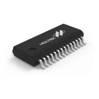
User Manuals: HOLTEK HT32F52230 32-bit microcontroller
Manuals and User Guides for HOLTEK HT32F52230 32-bit microcontroller. We have
1
HOLTEK HT32F52230 32-bit microcontroller manual available for free PDF download: User Manual
HOLTEK HT32F52230 User Manual (366 pages)
32-Bit Microcontroller with Arm Cortex-M0+ Core
Brand:
HOLTEK
| Category:
Microcontrollers
| Size: 3 MB
Table of Contents
Table of Contents
2
1 Introduction
17
Overview
17
Features
18
Device Information
21
Table 1. Features and Peripheral List
21
Block Diagram
22
Figure 1. Block Diagram
22
2 Document Conventions
23
Table 2. Document Conventions
23
3 System Architecture
24
Arm ® Cortex ® -M0+ Processor
24
Bus Architecture
25
Figure 2. Cortex ® -M0+ Block Diagram
25
Memory Organization
26
Figure 3. Bus Architecture
26
Figure 4. Memory Map
27
Memory Map
27
Table 3. Register Map
28
AHB Peripherals
29
APB Peripherals
29
Embedded Flash Memory
29
Embedded SRAM Memory
29
4 Flash Memory Controller (FMC)
30
Introduction
30
Features
30
Figure 5. Flash Memory Controller Block Diagram
30
Functional Descriptions
31
Flash Memory Map
31
Figure 6. Flash Memory Map
31
Flash Memory Architecture
32
Wait State Setting
32
Table 4. Flash Memory and Option Byte
32
Table 5. Relationship between Wait State Cycle and HCLK
32
Booting Configuration
33
Table 6. Boot Modes
33
Figure 7. Vector Remapping
33
Page Erase
34
Figure 8. Page Erase Operation Flowchart
34
Mass Erase
35
Figure 9. Mass Erase Operation Flowchart
35
Word Programming
36
Figure 10. Word Programming Operation Flowchart
36
Option Byte Description
37
Table 7. Option Byte Memory Map
37
Page Erase/Program Protection
38
Table 8. Access Permission of Protected Main Flash Page
38
Security Protection
39
Table 9. Access Permission When Security Protection Is Enabled
39
Register Map
40
Table 10. FMC Register Map
40
Register Descriptions
41
Flash Target Address Register - TADR
41
Flash Write Data Register - WRDR
42
Flash Operation Command Register - OCMR
43
Flash Operation Control Register - OPCR
44
Flash Operation Interrupt Enable Register - OIER
45
Flash Operation Interrupt and Status Register - OISR
46
Flash Page Erase/Program Protection Status Register - PPSR
48
Flash Security Protection Status Register - CPSR
49
Flash Vector Mapping Control Register - VMCR
50
Flash Manufacturer and Device ID Register - MDID
51
Flash Page Number Status Register - PNSR
52
Flash Page Size Status Register - PSSR
53
Device ID Register - DID
54
Flash Pre-Fetch Control Register - CFCR
55
Custom ID Register N - Cidrn ( N = 0 ~3)
56
5 Power Control Unit (PWRCU)
57
Introduction
57
Figure 11. PWRCU Block Diagram
57
Features
58
Functional Descriptions
58
VDD Power Domain
58
Figure 12. Power on Reset / Power down Reset Waveform
59
1.5 V Power Domain
60
Operation Modes
60
Table 11. Operation Mode Definitions
60
Table 12. Enter/Exit Power Saving Modes
61
Register Map
62
Table 13. Power Status after System Reset
62
Table 14. PWRCU Register Map
62
Register Descriptions
63
Power Control Status Register - PWRSR
63
Power Control Register - PWRCR
64
VDD Power Domain Test Register - PWRTEST
66
Low Voltage / Brown out Detect Control and Status Register - LVDCSR
67
6 Clock Control Unit (CKCU)
69
Introduction
69
Figure 13. CKCU Block Diagram
70
Features
71
Function Descriptions
71
High Speed External Crystal Oscillator - HSE
71
Figure 14. External Crystal, Ceramic, and Resonators for HSE
71
High Speed Internal RC Oscillator - HSI
72
Phase Locked Loop - PLL
73
Figure 15. PLL Block Diagram
73
Low Speed Internal RC Oscillator - LSI
74
Clock Ready Flag
74
Table 15. Output Divider2 Value Mapping
74
Table 16. Feedback Divider2 Value Mapping
74
System Clock (CK_SYS) Selection
75
HSE Clock Monitor
76
Clock Output Capability
76
Table 17. CKOUT Clock Source
76
Register Map
77
Table 18. CKCU Register Map
77
Register Descriptions
78
Global Clock Configuration Register - GCFGR
78
Global Clock Control Register - GCCR
80
Global Clock Status Register - GCSR
82
Global Clock Interrupt Register - GCIR
83
PLL Configuration Register - PLLCFGR
84
PLL Control Register - PLLCR
84
AHB Configuration Register - AHBCFGR
85
AHB Clock Control Register - AHBCCR
86
APB Configuration Register - APBCFGR
87
APB Clock Control Register 0 - APBCCR0
88
APB Clock Control Register 1 - APBCCR1
89
Clock Source Status Register - CKST
90
APB Peripheral Clock Selection Register 0 - APBPCSR0
91
APB Peripheral Clock Selection Register 1 - APBPCSR1
93
Low Power Control Register - LPCR
95
MCU Debug Control Register - MCUDBGCR
96
7 Reset Control Unit (RSTCU)
98
Introduction
98
Figure 16. RSTCU Block Diagram
98
Functional Descriptions
99
Power on Reset
99
System Reset
99
AHB and APB Unit Reset
99
Figure 17. Power on Reset Sequence
99
Register Map
100
Register Descriptions
100
Global Reset Status Register - GRSR
100
Table 19. RSTCU Register Map
100
AHB Peripheral Reset Register - AHBPRSTR
101
APB Peripheral Reset Register 0 - APBPRSTR0
102
APB Peripheral Reset Register 1 - APBPRSTR1
103
8 General Purpose I/O (GPIO)
104
Introduction
104
Figure 18. GPIO Block Diagram
104
Features
105
Functional Descriptions
105
Default GPIO Pin Configuration
105
General Purpose I/O - GPIO
105
Table 20. AFIO, GPIO and IO Pad Control Signal True Table
106
Figure 19. AFIO/GPIO Control Signal
106
GPIO Locking Mechanism
107
Register Map
107
Table 21. GPIO Register Map
107
Register Descriptions
108
Port a Data Direction Control Register - PADIRCR
108
Port a Input Function Enable Control Register - PAINER
109
Port a Pull-Up Selection Register - PAPUR
110
Port a Pull-Down Selection Register - PAPDR
111
Port a Open Drain Selection Register - PAODR
112
Port a Output Current Drive Selection Register - PADRVR
113
Port a Lock Register - PALOCKR
114
Port a Data Input Register - PADINR
115
Port a Output Data Register - PADOUTR
116
Port a Output Set/Reset Control Register - PASRR
117
Port a Output Reset Register - PARR
118
Port B Data Direction Control Register - PBDIRCR
119
Port B Input Function Enable Control Register - PBINER
120
Port B Pull-Up Selection Register - PBPUR
121
Port B Pull-Down Selection Register - PBPDR
122
Port B Open Drain Selection Register - PBODR
123
Port B Output Current Drive Selection Register - PBDRVR
124
Port B Lock Register - PBLOCKR
125
Port B Data Input Register - PBDINR
126
Port B Output Data Register - PBDOUTR
127
Port B Output Set/Reset Control Register - PBSRR
128
Port B Output Reset Register - PBRR
129
9 Alternate Function Input/Output Control Unit (AFIO)
130
Introduction
130
Figure 20. AFIO Block Diagram
130
Features
131
Functional Descriptions
131
External Interrupt Pin Selection
131
Figure 21. EXTI Channel Input Selection
131
Alternate Function
132
Lock Mechanism
132
Register Map
132
Table 22. AFIO Selection for Peripheral Map Example
132
Table 23. AFIO Register Map
132
Register Descriptions
133
EXTI Source Selection Register 0 - ESSR0
133
EXTI Source Selection Register 1 - ESSR1
134
GPIO X Configuration Low Register - Gpxcfglr, X = A, B
135
GPIO X Configuration High Register - Gpxcfghr, X = A, B
136
10 Nested Vectored Interrupt Controller (NVIC)
137
Introduction
137
Table 24. Exception Types
137
Features
138
Function Descriptions
139
Systick Calibration
139
Register Map
139
Table 25. NVIC Register Map
139
11 External Interrupt/Event Controller (EXTI)
140
Introduction
140
Features
140
Figure 22. EXTI Block Diagram
140
Function Descriptions
141
Wakeup Event Management
141
Figure 23. EXTI Wake-Up Event Management
141
External Interrupt/Event Line Mapping
142
Interrupt and Debounce
142
Figure 24. EXTI Interrupt Debounce Function
142
Register Map
143
Table 26. EXTI Register Map
143
Register Descriptions
144
EXTI Interrupt Configuration Register N - Exticfgrn, N = 0 ~ 15
144
EXTI Interrupt Control Register - EXTICR
145
EXTI Interrupt Edge Flag Register - EXTIEDGEFLGR
146
EXTI Interrupt Edge Status Register - EXTIEDGESR
147
EXTI Interrupt Software Set Command Register - EXTISSCR
148
EXTI Interrupt Wakeup Control Register - EXTIWAKUPCR
149
EXTI Interrupt Wakeup Polarity Register - EXTIWAKUPPOLR
150
EXTI Interrupt Wakeup Flag Register - EXTIWAKUPFLG
151
12 Analog to Digital Converter (ADC)
152
Introduction
152
Figure 25. ADC Block Diagram
152
Features
153
Function Descriptions
154
ADC Clock Setup
154
Channel Selection
154
Conversion Mode
154
Figure 26. One Shot Conversion Mode
155
Figure 27. Continuous Conversion Mode
155
Start Conversion on External Event
157
Figure 28. Discontinuous Conversion Mode
157
Sampling Time Setting
158
Data Format
158
Analog Watchdog
158
Table 27. Data Format in ADCDR [15:0]
158
Interrupts
159
Register Map
160
Table 28. A/D Converter Register Map
160
Register Descriptions
161
ADC Conversion Control Register - ADCCR
161
ADC Conversion List Register 0 - ADCLST0
163
ADC Conversion List Register 1 - ADCLST1
164
ADC Input Sampling Time Register - ADCSTR
165
ADC Conversion Data Register y - Adcdry, y = 0 ~ 7
166
ADC Trigger Control Register - ADCTCR
167
ADC Trigger Source Register - ADCTSR
168
ADC Watchdog Control Register - ADCWCR
169
ADC Watchdog Threshold Register - ADCTR
170
ADC Interrupt Enable Register - ADCIER
171
ADC Interrupt Raw Status Register - ADCIRAW
172
ADC Interrupt Status Register - ADCISR
173
ADC Interrupt Clear Register - ADCICLR
174
13 General-Purpose Timer (GPTM)
175
Introduction
175
Figure 29. GPTM Block Diagram
175
Features
176
Functional Descriptions
177
Counter Mode
177
Figure 30. Up-Counting Example
177
Figure 31. Down-Counting Example
178
Figure 32. Center-Aligned Counting Example
179
Clock Controller
180
Figure 33. GPTM Clock Selection Source
180
Trigger Controller
181
Figure 34. Trigger Controller Block
181
Slave Controller
182
Figure 35. Slave Controller Diagram
182
Figure 36. GPTM in Restart Mode
182
Figure 37. GPTM in Pause Mode
183
Figure 38. GPTM in Trigger Mode
184
Master Controller
185
Figure 39. Master Gptmn and Slave Gptmm/Mctmm Connection
185
Figure 40. MTO Selection
185
Channel Controller
186
Figure 41. Capture/Compare Block Diagram
186
Figure 42. Input Capture Mode
187
Figure 43. PWM Pulse Width Measurement Example
188
Input Stage
189
Figure 44. Channel 0 and Channel 1 Input Stages
189
Figure 45. Channel 2 and Channel 3 Input Stages
190
Figure 46. TI0 Digital Filter Diagram with N = 2
190
Quadrature Decoder
191
Figure 47. Input Stage and Quadrature Decoder Block Diagram
191
Table 29. Counting Direction and Encoding Signals
192
Figure 48. both TI0 and TI1 Quadrature Decoder Counting
192
Output Stage
193
Table 30. Compare Match Output Setup
193
Figure 49. Output Stage Block Diagram
193
Figure 50. Toggle Mode Channel Output Reference Signal - Chxpre = 0
194
Figure 51. Toggle Mode Channel Output Reference Signal - Chxpre = 1
194
Figure 52. PWM Mode Channel Output Reference Signal and Counter in Up-Counting Mode
195
Figure 53. PWM Mode Channel Output Reference Signal and Counter in Down-Counting Mode
195
Figure 54. PWM Mode Channel Output Reference Signal and Counter in Centre-Align Mode
196
Update Management
197
Figure 55. Update Event Setting Diagram
197
Single Pulse Mode
198
Figure 56. Single Pulse Mode
198
Figure 57. Immediate Active Mode Minimum Delay
199
Asymmetric PWM Mode
200
Figure 58. Asymmetric PWM Mode Versus Center Align Counting Mode
200
Trigger ADC Start
201
Register Map
201
Table 31. GPTM Register Map
201
Register Descriptions
202
Timer Counter Configuration Register - CNTCFR
202
Timer Mode Configuration Register - MDCFR
203
Timer Trigger Configuration Register - TRCFR
206
Table 32. GPTM Internal Trigger Connection
206
Timer Counter Register - CTR
207
Channel 0 Input Configuration Register - CH0ICFR
208
Channel 1 Input Configuration Register - CH1ICFR
209
Channel 2 Input Configuration Register - CH2ICFR
211
Channel 3 Input Configuration Register - CH3ICFR
212
Channel 0 Output Configuration Register - CH0OCFR
214
Channel 1 Output Configuration Register - CH1OCFR
216
Channel 2 Output Configuration Register - CH2OCFR
217
Channel 3 Output Configuration Register - CH3OCFR
219
Channel Control Register - CHCTR
221
Channel Polarity Configuration Register - CHPOLR
222
Timer Interrupt Control Register - DICTR
223
Timer Event Generator Register - EVGR
224
Timer Interrupt Status Register - INTSR
225
Timer Counter Register - CNTR
227
Timer Prescaler Register - PSCR
228
Timer Counter Reload Register - CRR
229
Channel 0 Capture/Compare Register - CH0CCR
230
Channel 1 Capture/Compare Register - CH1CCR
231
Channel 2 Capture/Compare Register - CH2CCR
232
Channel 3 Capture/Compare Register - CH3CCR
233
Channel 0 Asymmetric Compare Register - CH0ACR
234
Channel 1 Asymmetric Compare Register - CH1ACR
234
Channel 2 Asymmetric Compare Register - CH2ACR
235
Channel 3 Asymmetric Compare Register - CH3ACR
235
14 Basic Function Timer (BFTM)
236
Introduction
236
Features
236
Figure 59. BFTM Block Diagram
236
Functional Description
237
Repetitive Mode
237
Figure 60. BFTM - Repetitive Mode
237
One Shot Mode
238
Trigger ADC Start
238
Figure 61. BFTM - One Shot Mode
238
Figure 62. BFTM - One Shot Mode Counter Updating
238
Register Map
239
Register Descriptions
239
BFTM Control Register - BFTMCR
239
Table 33. BFTM Register Map
239
BFTM Status Register - BFTMSR
240
BFTM Counter Register - BFTMCNTR
241
BFTM Compare Value Register - BFTMCMPR
241
15 Single-Channel Timer (SCTM)
242
Introduction
242
Figure 63. SCTM Block Diagram
242
Features
243
Functional Descriptions
243
Counter Mode
243
Figure 64. Up-Counting Example
243
Clock Controller
244
Figure 65. SCTM Clock Selection Source
244
Trigger Controller
245
Figure 66. Trigger Control Block
245
Slave Controller
246
Figure 67. Slave Controller Diagram
246
Figure 68. SCTM in Restart Mode
246
Figure 69. SCTM in Pause Mode
247
Figure 70. SCTM in Trigger Mode
247
Channel Controller
248
Figure 71. Capture/Compare Block Diagram
248
Figure 72. Input Capture Mode
248
Input Stage
249
Figure 73. Channel Input Stages
249
Figure 74. TI Digital Filter Diagram with N = 2
249
Output Stage
250
Table 34. Compare Match Output Setup
250
Figure 75. Output Stage Block Diagram
250
Figure 76. Toggle Mode Channel Output Reference Signal - CHPRE = 0
251
Figure 77. Toggle Mode Channel Output Reference Signal - CHPRE = 1
251
Update Management
252
Figure 78. PWM Mode Channel Output Reference Signal
252
Register Map
253
Table 35. SCTM Register Map
253
Figure 79. Update Event Setting Diagram
253
Register Descriptions
254
Timer Counter Configuration Register - CNTCFR
254
Timer Mode Configuration Register - MDCFR
255
Timer Trigger Configuration Register - TRCFR
256
Timer Counter Register - CTR
257
Channel Input Configuration Register - CHICFR
258
Channel Output Configuration Register - CHOCFR
260
Channel Control Register - CHCTR
261
Channel Polarity Configuration Register - CHPOLR
262
Timer Interrupt Control Register - DICTR
263
Timer Event Generator Register - EVGR
264
Timer Interrupt Status Register - INTSR
265
Timer Counter Register - CNTR
266
Timer Prescaler Register - PSCR
266
Timer Counter Reload Register - CRR
267
Channel Capture/Compare Register - CHCCR
268
16 Watchdog Timer (WDT)
269
Introduction
269
Features
269
Figure 80. Watchdog Timer Block Diagram
269
Functional Description
270
Figure 81. Watchdog Timer Behavior
271
Register Map
272
Register Descriptions
272
Watchdog Timer Control Register - WDTCR
272
Table 36. Watchdog Timer Register Map
272
Watchdog Timer Mode Register 0 - WDTMR0
273
Watchdog Timer Mode Register 1 - WDTMR1
274
Watchdog Timer Status Register - WDTSR
275
Watchdog Timer Protection Register - WDTPR
276
Watchdog Timer Clock Selection Register - WDTCSR
277
17 Inter-Integrated Circuit (I C)
278
Introduction
278
Figure 82. I 2 C Module Block Diagram
278
Features
279
Functional Descriptions
279
Two Wire Serial Interface
279
START and STOP Conditions
279
Data Validity
280
Figure 83. START and STOP Condition
280
Figure 84. Data Validity
280
Addressing Format
281
Figure 85. 7-Bit Addressing Mode
281
Figure 86. 10-Bit Addressing Write Transmit Mode
282
Figure 87. 10-Bits Addressing Read Receive Mode
282
Data Transfer and Acknowledge
283
Figure 88. I 2 C Bus Acknowledge
283
Clock Synchronization
284
Arbitration
284
Figure 89. Clock Synchronization During Arbitration
284
Figure 90. Two Master Arbitration Procedure
284
General Call Addressing
285
Bus Error
285
Address Mask Enable
285
Address Snoop
285
Operation Mode
285
Figure 91. Master Transmitter Timing Diagram
286
Figure 92. Master Receiver Timing Diagram
288
Figure 93. Slave Transmitter Timing Diagram
289
Figure 94. Slave Receiver Timing Diagram
290
Conditions of Holding SCL Line
291
Table 37. Conditions of Holding SCL Line
291
I 2 C Timeout Function
292
Register Map
292
Table 38. I 2 C Register Map
292
Register Descriptions
293
I 2 C Control Register - I2CCR
293
I 2 C Interrupt Enable Register - I2CIER
294
I 2 C Address Register - I2CADDR
296
I 2 C Status Register - I2CSR
297
I 2 C SCL High Period Generation Register - I2CSHPGR
300
I 2 C SCL Low Period Generation Register - I2CSLPGR
301
Figure 95. SCL Timing Diagram
301
C Data Register - I2CDR
302
Table 39. I 2 C Clock Setting Example
302
I 2 C Target Register - I2CTAR
303
I 2 C Address Mask Register - I2CADDMR
304
I 2 C Address Snoop Register - I2CADDSR
305
I 2 C Timeout Register - I2CTOUT
306
18 Serial Peripheral Interface (SPI)
307
Introduction
307
Figure 96. SPI Block Diagram
307
Features
308
Function Descriptions
308
Master Mode
308
Slave Mode
308
SPI Serial Frame Format
309
Table 40. SPI Interface Format Setup
309
Figure 97. SPI Single Byte Transfer Timing Diagram - CPOL = 0, CPHA = 0
309
Figure 98. SPI Continuous Data Transfer Timing Diagram - CPOL = 0, CPHA = 0
310
Figure 99. SPI Single Byte Transfer Timing Diagram - CPOL = 0, CPHA = 1
310
Figure 100. SPI Continuous Transfer Timing Diagram - CPOL = 0, CPHA = 1
311
Figure 101. SPI Single Byte Transfer Timing Diagram - CPOL = 1, CPHA = 0
311
Figure 102. SPI Continuous Transfer Timing Diagram - CPOL = 1, CPHA = 0
312
Figure 103. SPI Single Byte Transfer Timing Diagram - CPOL = 1, CPHA = 1
312
Figure 104. SPI Continuous Transfer Timing Diagram - CPOL = 1, CPHA = 1
312
Status Flags
313
Table 41. SPI Mode Fault Trigger Conditions
314
Table 42. SPI Master Mode SEL Pin Status
314
Figure 105. SPI Multi-Master Slave Environment
314
Register Map
315
Table 43. SPI Register Map
315
Register Descriptions
316
SPI Control Register 0 - SPICR0
316
SPI Control Register 1 - SPICR1
317
SPI Interrupt Enable Register - SPIIER
319
SPI Clock Prescaler Register - SPICPR
320
SPI Data Register - SPIDR
321
SPI Status Register - SPISR
321
SPI FIFO Control Register - SPIFCR
323
SPI FIFO Status Register - SPIFSR
324
SPI FIFO Time out Counter Register - SPIFTOCR
325
19 Universal Synchronous Asynchronous Receiver Transmitter (USART)
326
Introduction
326
Figure 106. USART Block Diagram
326
Features
327
Function Descriptions
328
Serial Data Format
328
Figure 107. USART Serial Data Format
328
Baud Rate Generation
329
Table 44. Baud Rate Deviation Error Calculation - CK_USART = 8 Mhz
329
Figure 108. USART Clock CK_USART and Data Frame Timing
329
Table 45. Baud Rate Deviation Error Calculation - CK_USART = 20 Mhz
330
Table 46. Baud Rate Deviation Error Calculation - CK_USART = 24 Mhz
330
Table 47. Baud Rate Deviation Error Calculation - CK_USART = 40 Mhz
330
Hardware Flow Control
331
Figure 109. Hardware Flow Control between 2 Usarts
331
Figure 110. USART RTS Flow Control
331
Irda
332
Figure 111. USART CTS Flow Control
332
Figure 112. Irda Modulation and Demodulation
333
RS485 Mode
335
Figure 113. USART I/O and Irda Block Diagram
335
Figure 114. RS485 Interface and Waveform
336
Synchronous Master Mode
338
Figure 115. USART Synchronous Transmission Example
338
Figure 116. 8-Bit Format USART Synchronous Waveform
339
Interrupts and Status
340
Register Map
340
Table 48. USART Register Map
340
Register Descriptions
341
USART Data Register - USRDR
341
USART Control Register - USRCR
342
USART FIFO Control Register - USRFCR
344
USART Interrupt Enable Register - USRIER
345
USART Status & Interrupt Flag Register - USRSIFR
346
USART Timing Parameter Register - USRTPR
348
USART Irda Control Register - Irdacr
349
USART RS485 Control Register - RS485CR
350
USART Synchronous Control Register - SYNCR
351
USART Divider Latch Register - USRDLR
352
USART Test Register - USRTSTR
353
20 Universal Asynchronous Receiver Transmitter (UART)
354
Introduction
354
Figure 117. UART Block Diagram
354
Features
355
Function Descriptions
355
Serial Data Format
355
Figure 118. UART Serial Data Format
355
Baud Rate Generation
356
Table 49. Baud Rate Deviation Error Calculation - CK_UART = 8 Mhz
356
Figure 119. UART Clock CK_UART and Data Frame Timing
356
Table 50. Baud Rate Deviation Error Calculation - CK_UART = 20 Mhz
357
Table 51. Baud Rate Deviation Error Calculation - CK_UART = 24 Mhz
357
Table 52. Baud Rate Deviation Error Calculation - CK_UART = 40 Mhz
357
Interrupts and Status
358
Register Map
358
Table 53. UART Register Map
358
Register Descriptions
359
UART Data Register - URDR
359
UART Control Register - URCR
359
UART Interrupt Enable Register - URIER
361
UART Status & Interrupt Flag Register - URSIFR
362
UART Divider Latch Register - URDLR
364
UART Test Register - URTSTR
365
Advertisement
Advertisement
Related Products
HOLTEK HT32F52243
HOLTEK HT32F52253
HOLTEK HT32F52342
HOLTEK HT32F52352
HOLTEK HT32F52220
Holtek HT32F50231
Holtek HT32F50241
Holtek HT32F54231
Holtek HT32F54241
Holtek HT32F54243
HOLTEK Categories
Microcontrollers
Storage
Control Unit
Computer Hardware
Controller
More HOLTEK Manuals
Login
Sign In
OR
Sign in with Facebook
Sign in with Google
Upload manual
Upload from disk
Upload from URL