Sign In
Upload
Manuals
Brands
Anritsu Manuals
Radio
LMR Master S412E
Anritsu LMR Master S412E Manuals
Manuals and User Guides for Anritsu LMR Master S412E. We have
4
Anritsu LMR Master S412E manuals available for free PDF download: Programming Manual, Manual, User Manual, Maintenance Manual
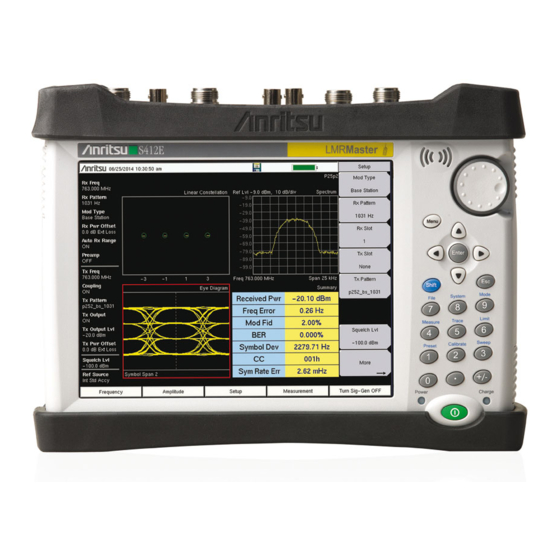
Anritsu LMR Master S412E Programming Manual (704 pages)
An Integrated, Handheld Multi-function Land Mobile Radio Test Tool
Brand:
Anritsu
| Category:
Test Equipment
| Size: 3.9 MB
Table of Contents
Table of Contents
3
Chapter 1-General Information
11
About this Manual
11
Introduction
11
Contacting Anritsu
11
Remote Programming Setup and Interface
12
Remote Access Password
12
Ethernet Interface Connection and Setup
12
Sending SCPI Commands
17
Chapter 2-Programming With SCPI
19
Introduction
19
Introduction to SCPI Programming
19
SCPI Common Commands
20
SCPI Required Commands
21
SCPI Optional Commands
21
Subsystem Commands
22
Command Names
22
Hierarchical Command Structure
23
Query Commands
24
Identifiers
25
Data Parameters
26
Data Parameter Notations
27
Unit Suffixes
27
Notational Conventions
28
Notational Examples
29
Command Terminators
29
Formatting Conventions
30
Parameter Names
30
Chapter 3-All Mode Commands
31
Introduction
31
Fetch GPS Subsystem
31
Instrument Subsystem
32
Mmemory Subsystem
35
Status Subsystem
39
System Subsystem
40
Sense]:Gps Subsystem
41
Chapter 4-Spectrum Analyzer Commands
43
Abort Subsystem
43
Calculate Subsystem
44
Configure Subsystem
63
Display Subsystem
65
Fetch Subsystem
67
Format Subsystem
69
Initiate Subsystem
70
Measure Subsystem
71
Mmemory Subsystem
74
READ Subsystem
77
Trace Subsystem
79
Trace Header Parameters
80
Trigger Subsystem
91
UNIT Subsystem
93
Sense] Subsystem
94
Chapter 5-VNA Commands
109
Introduction
109
Calculate Subsystem
109
Calculate:format Subsystem
111
Calculate:limit Subsystem
112
Calculate:marker Subsystem
130
Calculate:math Subsystem
137
Calculate:smoothing Subsystem
138
Calculate:transform Subsystem
139
Display Subsystem
142
Format Subsystem
148
Interpreting Returned Data Pair
149
Initiate Subsystem
151
Input Subsystem
153
Mmemory Subsystem
155
Source Subsystem
158
Source:correction:rvelocity Subsystem
158
System Subsystem
159
Trace Subsystem
160
Sense] Subsystem
172
[:Sense]:Application Subsystem
173
[:Sense]:Average Subsystem
174
[:Sense]:Calibration Subsystem
174
[:Sense]:Correction Subsystem
175
[:Sense]:Correction:ckit Subsystem
177
[:Sense]:Correction:ckit:user Subsystem
178
[:Sense]:Correction:collect Subsystem
179
[:Sense]:Frequency Subsystem
184
[:Sense]:Sweep Subsystem
187
[:Sense]:Trace Subsystem
188
Chapter 6-Vector Voltmeter Commands
191
Introduction
191
Fetch Subsystem
191
Mmemory Subsystem
193
Trace Subsystem
196
Sense] Subsystem
198
Chapter 7-Fixed Wimax Commands
201
Abort Subsystem
201
Configure Subsystem
202
Display Subsystem
205
Fetch Subsystem
207
Format Subsystem
210
Measure Subsystem
212
Mmemory Subsystem
216
READ Subsystem
219
Trace Subsystem
222
Sense] Subsystem
226
Chapter 9-LTE Commands
261
Abort Subsystem
261
Calculate Subsystem
262
Configure Subsystem
265
Display Subsystem
268
Fetch Subsystem
269
Format Subsystem
272
Initiate Subsystem
273
Measure Subsystem
274
READ Subsystem
277
UNIT Subsystem
280
Sense] Subsystem
281
Chapter 10-P25 Phase 1 Commands
288
Configure Subsystem
288
Display Subsystem
291
Fetch Subsystem
294
Format Subsystem
296
Interpreting Returned Data
297
Initiate Subsystem
299
Measure Subsystem
300
Mmemory Subsystem
302
READ Subsystem
305
Source Subsystem
307
Trace Subsystem
310
UNIT Subsystem
320
Sense] Subsystem
321
Chapter 11-P25 Phase 2 Commands
330
Configure Subsystem
330
Display Subsystem
333
Fetch Subsystem
337
Format Subsystem
339
Interpreting Returned Data
340
Initiate Subsystem
342
Measure Subsystem
343
Mmemory Subsystem
345
READ Subsystem
349
Source Subsystem
351
Trace Subsystem
355
UNIT Subsystem
365
Sense] Subsystem
366
Chapter 12-NXDN Commands
375
Abort Subsystem
375
Configure Subsystem
376
Display Subsystem
379
Fetch Subsystem
382
Format Subsystem
384
Interpreting Returned Data
385
Initiate Subsystem
387
Measure Subsystem
388
Mmemory Subsystem
390
READ Subsystem
393
Source Subsystem
395
Trace Subsystem
398
UNIT Subsystem
407
Sense] Subsystem
408
Chapter 13-Dpmr Commands
417
Abort Subsystem
417
Configure Subsystem
418
Display Subsystem
420
Fetch Subsystem
423
Format Subsystem
425
Interpreting Returned Data
426
Initiate Subsystem
428
Measure Subsystem
429
Mmemory Subsystem
431
READ Subsystem
434
Source Subsystem
436
UNIT Subsystem
448
Sense] Subsystem
449
Chapter 14-DMR 2 Commands
457
Abort Subsystem
457
Configure Subsystem
458
Display Subsystem
461
Fetch Subsystem
465
Format Subsystem
468
Interpreting Returned Data
469
Initiate Subsystem
471
Measure Subsystem
472
Mmemory Subsystem
475
READ Subsystem
479
Source Subsystem
482
UNIT Subsystem
495
Sense] Subsystem
496
Chapter 15-PTC Commands
505
Abort Subsystem
505
Configure Subsystem
506
Display Subsystem
508
Fetch Subsystem
511
Format Subsystem
513
Interpreting Returned Data
514
Initiate Subsystem
516
Measure Subsystem
517
Mmemory Subsystem
520
READ Subsystem
524
Source Subsystem
527
UNIT Subsystem
541
Sense] Subsystem
542
Chapter 16-NBFM Commands
551
Abort Subsystem
551
Configure Subsystem
552
Display Subsystem
555
Fetch Subsystem
559
Format Subsystem
563
Interpreting Returned Data
564
Initiate Subsystem
566
Measure Subsystem
567
Mmemory Subsystem
571
READ Subsystem
574
Source Subsystem
578
Trace Subsystem
581
UNIT Subsystem
589
Sense] Subsystem
590
Chapter 17-TETRA Commands
605
Abort Subsystem
605
Configure Subsystem
606
Display Subsystem
608
Fetch Subsystem
611
Format Subsystem
613
Interpreting Returned Data
614
Initiate Subsystem
616
Measure Subsystem
617
Mmemory Subsystem
619
READ Subsystem
622
Source Subsystem
624
Trace Subsystem
627
UNIT Subsystem
635
Sense] Subsystem
636
Chapter 18-AM/FM/PM Commands
643
Calculate Subsystem
643
Display Subsystem
647
Format Subsystem
648
Initiate Subsystem
650
Mmemory Subsystem
651
Trace Subsystem
654
Sense] Subsystem
655
Appendix A-Example
663
A-1 C/C++
663
Visual Basic
665
Appendix B-Commands by Mode
667
Advertisement
Anritsu LMR Master S412E Manual (256 pages)
Vector Network Analyzer for Anritsu RF and Microwave Handheld Instruments
Brand:
Anritsu
| Category:
Measuring Instruments
| Size: 23.54 MB
Table of Contents
Table of Contents
3
Chapter 1-General Information
11
Introduction
11
Contacting Anritsu
11
VNA Master Models
12
Identifying the Connections
13
Chapter 2-VNA Display Overview
15
Introduction
15
Powerful Display Capabilities
15
Flexible Features for Displaying Results
15
Active Trace
16
Changing the Active Trace
16
Touch Screen Trace Features
17
Trace Description
17
Example Measurement Displays
18
Vector Network Analyzer MG PN: 10580-00289 Rev. K
19
Marker and Limit Capabilities
21
Marker Description
21
Selecting the Readout Style for each Marker
21
Displaying Markers on the Screen
21
Setting up Delta Markers
22
Setting up Limits
22
Markers on a Touch Screen
22
Trace Math Capabilities
23
Chapter 3-VNA Fundamentals
25
Introduction
25
Option 16 (S412E LMR Master)
25
S-Parameters
26
Additional Examples
26
VNA Master Architecture
27
Calculating and Displaying S-Parameters
30
Extracting more Information by Using Markers
32
How Bias Is Generated
32
Chapter 4-VNA Measurements
33
Introduction
33
Select Measurement Type - VNA Versus Field
33
Touch Screen Trace Features
33
Markers on a Touch Screen
33
1-Port Cable Measurement
33
Setup Considerations
33
Measurement Readout and Interpretation
34
1-Port Smith Chart Tuning Example
37
2-Port Filter Measurement
39
Introduction
39
Setup Considerations
39
Measurement Readout and Interpretation
39
2-Port Amplifier Measurement
42
Introduction
42
Setup Considerations
42
Measurement Readout and Interpretation
42
Waveguide Considerations
45
Introduction
45
Setup Considerations
45
Measurement Readout and Interpretation
46
Calibration Considerations
48
Ms20Xxb 1-Path 2-Port Calibration
49
Ms20Xxc Full 2-Port Calibration
50
Calibration Data and Indications
51
Cal Type
52
Chapter 5-Field Measurements
53
Introduction
53
Options
53
Field Measurements View Setting
53
Select Measurement Type - Field Versus VNA
53
Touch Screen Trace Features
53
Markers on a Touch Screen
53
Measurement Setup
54
Setting the Frequency Range
54
Setting the Start and Stop Frequencies
55
Setting Data Points
55
Calibration
55
Graph Type Selector List Box
56
Field Measurements View Versus VNA Measurements View
56
Insertion Loss in Display Type Single
57
VSWR and Return Loss in Display Type Dual
58
Insertion Loss and Return Loss in Display Type Overlay
59
Field View Menus
60
VNA Measurements
60
Return Loss/Vswr
61
Cable Loss
64
Distance-To-Fault (DTF)
66
DTF Measurement Calculations
69
5-10 Phase Measurements
70
1-Port Phase Measurement
70
2-Port Phase Measurement
71
Smith Chart
73
Smith Chart Measurement
73
5-12 Log Mag Display Types
75
Typical Log Magnitude Measurement
75
Dual Channel Filter Tuning Measurement
78
Chapter 6-VNA View Menus
81
Introduction
81
VNA Key Functions
81
Domain Setup Menus
83
Freq Menu
84
Setup Domain Menu
85
Time Menu
86
Time Info List Box
87
Windowing Menu
88
Distance Setup Menu
89
Additional Dist Setup Menu (Coax)
90
Cable List Menu (Coax)
91
Additional Dist Setup Menu (Waveguide)
92
Distance Info List Box for Cable
93
Distance Info List Box for Waveguide
93
FGT Menu
94
Gate Menu
95
Gate Setup Menu (Continued)
96
Gate Shape Menu
97
Calibration Menus
98
Calibration Menu
99
Calibration Menu with Thru
105
Calibration Line Setup Menu
107
Existing Calibration Information List Box
108
Additional Calibration Considerations
108
DUT Port Setup Menu (Coax)
109
Cal Kit Definition Menus for Coax
110
DUT Connector Selector List Box for Coax
111
SOLT - Coax Menu
112
DUT Port Setup Menu (Waveguide)
113
Cal Kit Definition Menus for Waveguide
114
DUT Connector Selector List Box for Waveguide
115
SOLT - WG Menu
116
Calibration Types
117
Limit Menus
118
Limit Menu
119
Limit Edit Menu
120
Marker Menus
121
Marker Menu
122
Marker Search Menu
123
Readout Format Menu
124
Measurement Menus
125
Measure Menu
126
S-Parameter List Box
127
S-Parameter Menu
128
Domain Menu
129
Low Pass Mode Menu
130
Band Pass Mode Menu
130
Number of Traces Menu
131
Trace Format Menu
132
Sweep Menu - Ms20Xxc
133
Sweep Menu - Ms20Xxb and S412E
134
Configure Ports Menu
135
Bias Tee Setup Menu
136
Bias Tee Menu (Ms20Xxc Only)
137
Source Power Menu (Ms20Xxc Only)
138
Source Power Menu (Ms20Xxb and S412E Only)
138
Preset Menu
139
Scale Menu
140
Smith Scale Menu
141
Polar Scale Menu
142
System Menus
143
Application Options Menu (VNA Mode)
144
Application Options Menu (SPA Mode) VNA Master
145
Application Options Menu (SPA Mode) LMR Master
146
Time Domain Options Menu
147
Trace Menu
148
Trace Math Menu
149
Introduction
151
Chapter 7 -Field View Menus
152
Field View Menu Group (Field View)
152
Field View Frequency Menus
153
Freq/Dist Menu (Distance-Based)
154
Distance Menus
155
DTF Setup Menu
156
Cable List Menu
157
Windowing Menu
158
Scale Menus
159
Scale Menu
160
Scale Menu – Dual or Overlay
161
Sweep Menus
162
Sweep Menu
163
Avg/Smooth Menu
164
Measure Menus
165
Measure Menu – Dual
166
Marker Menu
167
Calibration Menu
168
Application Options Menu
169
Introduction
171
Chapter 9 -Distance Domain
172
VNA Master Implementation
172
Time Domain – Impulse Response
175
Step Response Versus Impulse Response
176
Frequency Gated by Time
179
Waveguide with Dispersion Compensation
181
Phasor Impulse
183
Windowing
185
In the Additional Dist Setup Submenu:
186
Time and Distance Information
187
Introduction
189
Chapter 8 -Time Domain, Option 2
190
VNA Master Implementation
190
Windowing
192
Distance Information
194
Introduction
195
How Bias Is Generated
196
Chapter 10 -Bias Tee, Option 10
199
Bias Tee When Making 2-Port Gain Measurements
199
Bias Tee Menus (Ms20Xxc, MS2026B, and MS2028B)
201
Bias Tee Setup Menu
202
Bias Tee Menu
203
Bias Tee Menus (Field Measurements View)
204
Bias Tee Setup Menu
205
Bias Tee Menus (Ms20Xxb and S412E in VNA View)
206
Introduction
207
Chapter 11 -Vector Voltmeter, Option 15
208
Getting Started
208
Using Vector Voltmeter Mode for the First Time
209
How the VVM Function Works
210
Simple Measurement Using CW Display
211
Calibration Correction
212
Relative Measurements Using CW Display
216
Measurements Using Comparison Table Display
218
Vector Voltmeter Menus
220
Table Menu
221
Save/Recall Menu
222
Introduction
223
Chapter 12 -Balanced Ports, Option 77
225
Typical Measurements
225
A-1 Vector Network Analyzer Formulas
229
Appendix A-Formulas
230
Propagation
230
B-1 Introduction
231
Appendix B-Windowing
232
Rectangular Windowing
232
Nominal Side Lobe Windowing
233
Low Side Lobe Windowing
234
Minimum Side Lobe Windowing
235
C-1 Introduction
237
C-3 Self Test or Application Self Test Error Messages
238
Application Self Test Results Window — VNA
240
Application Self Test Results Window — SPA
241
C-4 Operation Error Messages
242
Appendix C-Error Messages
243
PMON PLD Fail
243
Bias Tee State Cannot be Changed During Calibration
244
Limit Is Not Available for this Graph Type
245
Anritsu LMR Master S412E User Manual (150 pages)
An Integrated, Handheld Multi-function Land Mobile Radio
Brand:
Anritsu
| Category:
Radio
| Size: 12.72 MB
Table of Contents
Table of Contents
3
Chapter 1-General Information
9
Introduction
9
Additional Documentation
9
Contacting Anritsu for Sales and Service
10
Instrument Description
11
Available Models
11
Additional Options
12
Instrument Care and Preventive Maintenance
13
Connector Care
13
ESD Caution
14
Battery Replacement
14
Calibration and Verification
16
Secure Environment Workplace
17
LMR Master Memory Types
17
Erase All User Files in Internal Memory
17
Recommended Usage in a Secure Environment
18
Chapter 2-Instrument Overview
19
Introduction
19
Turning on the LMR Master
19
Front Panel Overview
19
Front Panel Keys
21
S412E UG PN: 10580-00318 Rev. P
23
Touch Screen Keys
24
Keypad Menu Keys (1 to 9)
24
LED Indicators
24
Display Overview
25
Display Settings
26
Test Panel Connector Overview
27
Test Panel Connectors
28
Symbols and Indicators
29
Battery Symbols
31
Additional Symbols
32
Data Entry
32
Numeric Values
32
Parameter Setting
32
Text Entry
33
Mode Selector Menu
34
Soft Carrying Case
35
2-10 Tilt Bail Stand
36
Chapter 3-Quick Start Guide
37
Introduction
37
Measurement Mode Selection
37
CW Signal Generator
38
Vector Network Analyzer
39
Field Mode Display Vs. Standard VNA Display
39
Select the Measurement Type
40
Set the Frequency
40
Set the Scale
40
Turn on Markers
40
Peak and Valley Search Markers
40
Set up Delta Markers
41
Set a Single Limit Line
41
Set up Distance Domain
42
Calibration Considerations
42
Spectrum Analyzer
45
Set Start and Stop Frequencies
45
Enter the Center Frequency
45
Select a Signal Standard
45
Set the Measurement Bandwidth
45
Set the Amplitude
46
Power Offset Set up for Compensating External Loss
46
Set the Span
46
Single Limit Line
47
Create a Limit Envelope
47
Setting up Markers
48
Select a Smart Measurement Type
49
NBFM Analyzer
50
Set the Receiver (Rx) Frequency
50
Set the Signal Source Transmit (Tx) Frequency
50
Rx and Tx Power Offset
51
Select the Measurement Types
51
LMR Digital Demodulation Signal Analyzers
53
Set the Receiver (Rx) Frequency
53
Set the Signal Source Transmit (Tx) Frequency
53
Rx and Tx Power Offset
54
Select the Measurement Types
54
Saving Measurements
59
External Power on
60
Chapter 4-File Management
61
Introduction
61
File Types
61
Managing Files
62
Save Files
62
Save Dialog Box
63
Quick Name Keys
63
Recall Files
64
Recall Dialog Box
64
Copy Files
65
Delete Files
66
Delete Dialog Box
66
File Menu Overview
67
File Menu
68
Save Menu
69
Save Location Menu
70
Save on Event Menu
71
Recall Menu
72
Copy Menu
73
Delete Menu
74
Chapter 5-System Operations
75
Introduction
75
System Menu Group Overview
76
System Menu Map 1
77
System Menu Map 2
77
System Menu
78
Application Options Menu
79
VNA Mode
79
SPA Mode
80
DMR 2 Mode
81
P25 Mode
81
P25P2 Mode
82
NXDN Mode
82
PTC Mode
83
TETRA Mode
83
Updating Signal Generator Patterns
84
System Options Menu
85
System Options 2/2 Menu
86
Power-On Menu
88
Display Settings Menu
89
Reset Menu
90
Preset Menu
91
Self Test
91
5-10 Updating the LMR Master Firmware
92
Chapter 6-Ethernet Connectivity
93
Introduction
93
Ethernet Connection
93
Network Connection
93
Ethernet Direct Connection
93
Ethernet Configuration on the LMR Master
94
LAN Connection
94
Ethernet Config
96
Ethernet Menu
97
Dhcp
98
Example 1
99
Example 2
99
Ipconfig Tool
99
Ping Tool
100
Chapter 7-Anritsu PC Software Tools
101
Introduction
101
Anritsu Tool Box
101
Line Sweep Tools
102
Master Software Tools
103
Easymap Tools
104
Chapter 8-Bias Tee (Option 10)
105
Overview
105
Bias Tee in VNA Mode
105
Bias Tee in SPA Mode
107
Chapter 9-GPS (Option 31)
109
Introduction
109
Activating the GPS Feature
109
Saving and Recalling Traces with GPS Information
111
Saving Traces with GPS Information
111
Recalling GPS Information
111
GPS Menu
111
Chapter 10-Web Remote Control
113
10-1 Introduction
113
10-2 Setup
113
LAN Connection
113
Connection to a Wi-Fi Portable Router
114
10-3 Web Remote Control Interface
116
Menu Bar
118
Remote Control
119
File List
121
Device Management
121
Logout
122
Appendix A-Measurement Guides
123
A-1 Introduction
123
A-1 Introduction
124
Appendix B-Error Messages
125
Introduction
125
Reset Options
125
Reset Via Instrument Menus
125
Reset from off Condition
125
B-1 Introduction
125
Self Test
126
Application Self Test
127
VNA Mode Self Test (Vector Network Analyzer Mode Only
127
Spectrum Analyzer Mode Self Test
128
CW Signal Generator Mode Self Test
128
NBFM, P25/P25P2, NXDN, Dpmr, DMR 2, PTC, and TETRA Self Test
129
Operation Error Messages
130
Fan Failure
130
High Temp Warning
130
Operation Not Permitted in Recall Mode
131
Power Supply
131
Error Saving File. General Error Saving File
131
C-1 Introduction
133
D-1 Introduction
135
Advertisement
Anritsu LMR Master S412E Maintenance Manual (122 pages)
LMR Master Vector Network/Spectrum Analyzer
Brand:
Anritsu
| Category:
Measuring Instruments
| Size: 12.85 MB
Table of Contents
Signal Generator
1
Safety Symbols
5
Table of Contents
7
Chapter 1-General Information
9
Introduction
9
Product Description
9
Related Documents
10
Options
10
Anritsu Customer Service Centers
11
Recommended Test Equipment
11
Replaceable Parts and Assemblies
14
Performance Verification Procedures
16
Chapter 2-Vector Network Analyzer Verification
17
Introduction
17
Frequency Accuracy
17
Transmission Dynamic Range
18
Return Loss Measurement Accuracy Verification
19
Chapter 3-Spectrum Analyzer Verification
21
Introduction
21
Frequency Accuracy Verification and Adjustment
22
Residual Spurious Response
24
Displayed Average Noise Level (DANL)
26
Single Side Band (SSB) Phase Noise
28
Spurious Response (Second Harmonic Distortion)
29
Resolution Bandwidth Accuracy
31
Amplitude Accuracy
32
Third Order Intercept (TOI)
37
Chapter 4-CW Signal Generator Verification
43
Introduction
43
Frequency Accuracy Verification
43
Chapter 5 -Option Verification
47
GPS Verification, Option 31
47
Fixed Wimax Signal Analyzer Verification, Option 46 and 47
50
Mobile Wimax Signal Analyzer Verification, Option 66 and 67
54
P25/P25P2 Modulation Fidelity Verification, Option 521 and 522
60
NXDN Modulation Fidelity Verification, Option 531 and 532
62
LTE Signal Analyzer Verification, Option 541 and 542
63
TETRA EVM Verification, Option 581 and 582
67
DMR2 Modulation Fidelity Verification, Option 591 and 592
68
Positive Train Control (PTC) Verification, Option 721 and 722
69
Chapter 6-Battery Information and Replacement
71
Introduction
71
Replaceable Parts and Assemblies
71
Battery Information
71
Battery Pack Removal and Replacement
73
Chapter 7-Assembly Replacement
75
Replaceable Parts List
75
Opening the S412E Case
75
PCB Assembly Replacement
78
SPA Assembly Replacement
79
SPA and MB/VNA N Connector Replacement
80
GPS (Option 31) Replacement
81
Signal Generator Replacement
82
Main/Vna PCB Assembly Replacement
85
Fan Assembly Replacement
85
7-10 LCD Assembly Replacement
86
LCD Backlight PCB Removal and Replacement
88
7-12 Keypad and Keypad PCB Replacement
89
7-13 Touchscreen Replacement
90
Chapter 8-Troubleshooting
91
Introduction
91
Turn-On Problems
91
Operating Problems
92
Appendix A-Test Records
95
Introduction
95
A-1 Introduction
95
Test Records for VNA Verification
96
Test Records for Spectrum Analyzer Verification
97
Test Records for Signal Generator Verification
110
Test Records for Options Verification
111
Advertisement
Related Products
Anritsu Site Master S332C
Anritsu Site Master S251C
Anritsu Site Master S332D
Anritsu Site Master S810D
Anritsu Site Master S820D
Anritsu Site Master S331L
Anritsu Site Master S113BQ
Anritsu OC-3/12 STM-1/4
Anritsu Site Master S112
Anritsu SM/PL-1
Anritsu Categories
Measuring Instruments
Test Equipment
Portable Generator
Control Unit
Thermometer
More Anritsu Manuals
Login
Sign In
OR
Sign in with Facebook
Sign in with Google
Upload manual
Upload from disk
Upload from URL