Sign In
Upload
Manuals
Brands
Anritsu Manuals
Measuring Instruments
Site Master S332D
Anritsu Site Master S332D Manuals
Manuals and User Guides for Anritsu Site Master S332D. We have
3
Anritsu Site Master S332D manuals available for free PDF download: User Manual, Programming Manual, Maintenance Manual
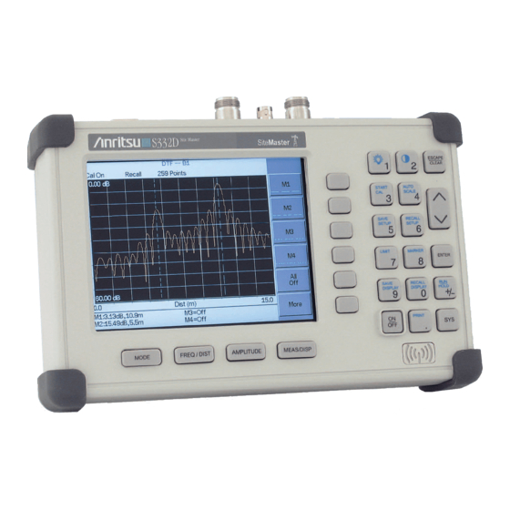
Anritsu Site Master S332D User Manual (174 pages)
Cable and Antenna Analyzer
Brand:
Anritsu
| Category:
Measuring Instruments
| Size: 2 MB
Table of Contents
Table of Contents
4
Chapter 1 - General Information
7
Introduction
7
Description
7
Standard Accessories
7
Printers
8
Optional Accessories
9
Performance Specifications
10
Preventive Maintenance
15
Calibration
15
Instacal Module
16
Annual Verification
16
ESD Precautions
16
Mode References
16
Chapter 2 - Functions and Operations
18
Introduction
18
Test Connector Panel
18
Display Overview
20
Front Panel Overview
21
Function Hard Keys
22
Keypad Hard Keys
23
Soft Keys
25
T1 Tester Mode Menus (Option 50)
50
E1 Tester Mode Menus (Option 50)
53
Transmission Measurement Menus
55
Power Meter Menus (Option 29)
62
Symbols
63
Self Test
63
Error Messages
64
Battery Information
69
Charging a New Battery
69
Determining Remaining Battery Life
70
Important Battery Information
72
Chapter 3 - Getting Started
73
Introduction
73
Power on Procedure
73
Cable and Antenna Analyzer Mode
74
Spectrum Analyzer Mode
82
All Modes
86
Save and Recall a Setup
86
Save and Recall a Display
86
Changing the Units
87
Changing the Language
87
Adjusting Markers
87
Adjusting Limits
88
Adjusting the Display Contrast
89
Adjusting the Backlight Intensity
89
Printing
90
Using the Soft Carrying Case
91
Chapter 4 - Cable and Antenna Analyzer Measurements
92
Introduction
92
Line Sweep Fundamentals
92
CW Mode
93
Information Required for a Line Sweep
94
Typical Line Sweep Test Procedures
94
Chapter 5 - Spectrum Analyzer Measurements
101
Introduction
101
Measurement Fundamentals
101
Preamplifier
103
Preamplifier Operation
103
Preamplifier Measurement Example
104
Dynamic Attenuation Control
106
Frequency Converter Interface (Option 6)
107
Introduction
107
Bias Tee (Option 10)
107
Selecting the Signal Standard and Channel
108
Field Strength Measurements
109
Occupied Bandwidth
110
Channel Power Measurement
112
Adjacent Channel Power Ratio
114
Interference Analysis
116
AM/FM Demodulation
117
Demodulation Procedure
117
Carrier to Interference Ratio (C/I)
119
Procedure
119
Chapter 6 - Power Measurement
122
Introduction
122
Power Measurement
122
Required Equipment
122
Chapter 7 - T1 Measurements
124
Introduction
124
T1 Fundamentals
124
Network Equipment
125
Testing T1 Circuits
126
In Service Testing
126
Out-Of-Service Testing
129
Measurement Procedure
130
Chapter 8 - E1 Measurements
134
Introduction
134
E1 Fundamentals
134
Network Equipment
135
Testing E1 Circuits
136
In Service Testing
136
Out-Of-Service Testing
141
Chapter 9 - Transmission Measurement
144
Introduction
144
Measuring Active Devices
144
Calibration
144
Transmission Measurement Procedure
146
Chapter 10 - Handheld Software Tools
147
Introduction
147
Features
147
System Requirements
147
Installation
148
Using Handheld Software Tools
149
Downloading Traces
149
Plot Capture to the PC
150
Plot Upload to the Instrument
150
Plot Properties
150
Appendix A Reference Data
157
Coaxial Cable Technical Data
157
Appendix B Windowing
161
Introduction
161
Examples
161
Appendix C Signal Standards
164
Introduction
164
Index
170
Advertisement
Anritsu Site Master S332D Programming Manual (132 pages)
Cable and Antenna Analyzer
Brand:
Anritsu
| Category:
Measuring Instruments
| Size: 0 MB
Table of Contents
Table of Contents
3
Programming Overview
7
Documentation Conventions
8
Exiting Remote Mode
8
Write Cycle Limitation of EEPROM
8
Control Byte Summary
9
Control Byte Descriptions
13
Setup System - Control Byte #1 (01H)
13
Set Site Master VNA Frequency - Control Byte #2 (02H)
13
Select Measurement Mode - Control Byte #3 (03H)
14
Set Site Master VNA Scale - Control Byte #4 (04H)
14
Set Site Master VNA Marker - Control Byte #5 (05H)
15
Set Site Master VNA Single Limit - Control Byte #6 (06H)
15
Set DTF Parameter - Control Byte #7 (07H)
16
Set Time/Date - Control Byte #8 (08H)
17
Set Reference Number - Control Byte #9 (09H)
17
Serial Port Echo On/Off - Control Byte #10 (0Ah)
17
Site Master VNA Single Sweep Mode On/Off - Control Byte #11 (0Bh)
18
Watch-Dog Timer On/Off - Control Byte #12 (0Ch)
18
Sequence Site Master Calibration - Control Byte #13 (0Dh)
19
Set Site Master Data Points - Control Byte #14 (0Eh)
19
Set Site Master Calibration Mode - Control Byte #15 (0Fh)
19
Store Sweep Trace - Control Byte #16 (10H)
20
Recall Sweep Trace - Control Byte #17 (11H)
20
Save System Setup - Control Byte #18 (12H)
26
Recall System Setup - Control Byte #19 (13H)
27
Query System Status - Control Byte #20 (14H)
27
Trigger Self-Test - Control Byte #21 (15H)
34
Read Fail Counter - Control Byte #22 (16H)
35
Query Trace Names - Control Byte #24 (18H)
35
Delete Sweep Trace - Control Byte #25 (19H)
35
Upload SPA Sweep Trace - Control Byte #26 (1Ah)
36
Query Sweep Memory - Control Byte #27 (1Bh)
39
Upload Site Master VNA Sweep Trace - Control Byte #28 (1Ch)
39
Query System Status - Control Byte #29 (1Dh)
42
Select Printer Type - Control Byte #30 (1Eh)
54
Select DTF Windowing - Control Byte #31 (1Fh)
55
Set Site Master VNA Trace Math - Control Byte #32 (20H)
55
Recall Sweep Trace - Control Byte #33 (21H)
55
Set Site Master VNA Trace Overlay - Control Byte #34 (22H)
67
Set SPA A/B Trace - Control Byte #35 (23H)
67
Upload Sweep Trace - Control Byte #36 (24H)
68
Get Options - Control Byte #37 (25H)
77
Query Power Level - Control Byte #39 (27H) (Option 29 Only)
78
Set Power Meter Units - Control Byte #40 (28H) (Option 29 Only)
78
Power Meter Relative Mode On/Off - Control Byte #41 (29H) (Option 29 Only)
79
Power Meter Offset Mode On/Off - Control Byte #42 (2Ah) (Option 29 Only)
79
Power Meter Zero Mode On/Off - Control Byte #43 (2Bh) (Option 29 Only)
79
Power Meter RMS Averaging On/Off - Control Byte #44 (2Ch) (Option 29 Only)
79
Power Meter Center Freq and Span Setup - Control Byte #45 (2Dh) (Option 29 Only)
80
Trigger Sweep - Control Byte #48 (30H)
80
Trigger Sweep - Control Word (Aa30H)
80
Check Battery Status - Control Byte #50 (32H)
80
Set SPA Minimum Sweep Time - Control Byte #53 (35H)
81
Set Trigger Position - Control Byte #54 (36H)
81
Set Video Trigger Level - Control Byte #55 (37H)
81
Automatically Save Runtime Setup - Control Byte #64 (40H)
82
Enter Remote Mode - Control Byte #69 (45H)
82
Enter Remote Mode Immediately - Control Byte #70 (46H)
82
Write Custom Cable - Control Byte #80 (50H)
83
Recall Custom Cable - Control Byte #81 (51H)
83
Write Antenna - Control Byte #82 (52H)
84
Recall Antenna - Control Byte #83 (53H)
84
Set Field Strength Measurement - Control Byte #84 (54H)
85
Set Channel Power - Control Byte #85 (55H)
85
Read Channel Power - Control Byte #86 (56H)
86
Set Adjacent Channel Power Ratio (ACPR) - Control Byte #87 (57H)
86
Read Adjacent Channel Power Ratio (ACPR) - Control Byte #88 (58H)
86
Read Signal Standard Name - Control Byte #89 (59H)
87
Measure OCC BW % of Power - Control Byte #96 (60H)
87
Measure OCC BW Db down - Control Byte #97 (61H)
88
Set Bias Tee Function - Control Byte #98 (62H) (Option 10 Only)
88
Set Spectrum Analyzer Start/Stop Frequency - Control Byte #99 (63H)
89
Set Spectrum Analyzer Center Freq./Span - Control Byte #100 (64H)
89
Set Spectrum Analyzer Scale - Control Byte #101 (65H)
89
Set Spectrum Analyzer Marker - Control Byte #102 (66H)
90
Set Spectrum Analyzer Single Limit - Control Byte #103 (67H)
90
Set Spectrum Analyzer Peak Hold - Control Byte #105 (69H)
91
Set Spectrum Analyzer Resolution Bandwidth - Control Byte #106 (6Ah)
91
Set Spectrum Analyzer Video Bandwidth - Control Byte #107 (6Bh)
91
Set Spectrum Analyzer Sweep Mode - Control Byte #108 (6Ch)
92
Set Spectrum Analyzer Marker to Peak - Control Byte #109 (6Dh)
92
Set Spectrum Analyzer Marker to Center - Control Byte #110 (6Eh)
92
Set Spectrum Analyzer Attenuation - Control Byte #111 (6Fh)
93
Set Site Master VNA Segmented Limit Lines - Control Byte #112 (70H)
93
Set Spectrum Analyzer Multiple Limit - Control Byte #113 (71H)
94
Set Return Spectrum Analyzer Sweep Time - Control Byte #114 (72H)
95
Set Reference Level Offset - Control Byte #115 (73H)
95
Read Marker Value - Control Byte #117 (75H)
96
Set Sweep Averaging - Control Byte #118 (76H)
96
Field Instacal - Control Byte #120 (78H)
96
Read Instacal Module ASCII Serial Number - Control Byte #124 (7Ch)
97
Set Site Master Marker (Peak/Valley) - Control Byte #129 (81H)
97
Set / Reset Spectrum Analyzer External Reference - Control Byte #133 (85H)
97
Check Spectrum Analyzer External Reference - Control Byte #134 (86H)
98
Set SPA Preamp State (On/Off/Auto) - Control Byte #136 (88H)
98
Set Spectrum Analyzer Units - Control Byte #140 (8Ch)
98
Set Spectrum Analyzer Resolution Bandwidth - Control Byte #141 (8Dh)
99
Set Spectrum Analyzer Video Bandwidth - Control Byte #142 (8Eh)
99
Set Spectrum Analyzer Attenuation - Control Byte #143 (8Fh)
99
Set AM/FM Demodulation - Control Byte #145 (91H)
100
Set Baud Rate - Control Byte #197 (C5H)
101
Set Language - Control Byte #198 (C6H)
101
Query Time - Control Byte #208 (D0H)
101
Read ASCII Serial Number - Control Byte #225 (E1H)
102
Exit Remote Mode - Control Byte #255 (Ffh)
102
Set T1 Transmission Level - Control Word (A001H) (Option 50 Only)
102
Set T1/E1 Clock Source - Control Word (A002H) (Option 50 Only)
102
Set T1/E1 Pattern - Control Word (A003H) (Option 50 Only)
103
Set T1/E1 Error Insert Type/Value - Control Word (A004H) (Option 50 Only)
103
Set T1/E1 Framing Mode - Control Word (A005H) (Option 50 Only)
104
Start and Stop T1/E1 Measurement - Control Word (A006H) (Option 50 Only)
104
Insert Error for T1/E1 Measurement - Control Word (A007H) (Option 50 Only)
104
Get T1/E1 Pattern - Control Word (A008H) (Option 50 Only)
104
Get T1/E1 Frame Sync Status - Control Word (A009H) (Option 50 Only)
105
Get T1/E1 Pattern Sync Status - Control Word (A00Ah) (Option 50 Only)
105
Get T1/E1 Carrier Status - Control Word (A00Bh) (Option 50 Only)
105
Get T1/E1 Error Type and Number - Control Word (A00Ch) (Option 50 Only)
105
Set T1/E1 Line Coding Options - Control Word (A00Dh) (Option 50 Only)
106
Set E1 Impedance Options - Control Word (A00Eh) (Option 50 Only)
106
Read T1/E1 Volts Peak-To-Peak - Control Word (A00Fh) (Option 50 Only)
106
Set T1/E1 Receive Input Configuration Options - Control Word (A013H) (Option 50 Only)
107
Set T1/E1 Measurement Duration - Control Word (A014H) (Option 50 Only)
107
Set T1/E1 Data Logging - Control Word (A015H) (Option 50 Only)
107
Read T1/E1 Dbdsx - Control Word (A016H) (Option 50 Only)
108
Read T1/E1 Frequency - Control Word (A017H) (Option 50 Only)
108
Read T1/E1 Frequency Cal - Control Word (A018H) (Option 50 Only)
108
Set T1/E1 Frequency Cal - Control Word (A019H) (Option 50 Only)
108
Select Spa/Power Meter Signal Standard - Control Word (A103H)
109
Select Spa/Power Meter Channel - Control Word (A104H)
109
Read External Module Name - Control Word (A201H) (Option 6 Only)
109
Read External Module Serial Number - Control Word (A202H) (Option 6 Only)
110
Read External Module Frequency Range - Control Word (A203H) (Option 6 Only)
110
Read Module Fail Counter - Control Word (A204H) (Option 6 Only)
110
Clear Module Fail Counter - Control Word (A205H) (Option 6 Only)
111
Remote Self Test - Control Word (Aa15H)
111
Programming Examples
114
Examples in C
114
Example in Visual Basic
123
Parameter Definitions
125
Spectrum Analyzer Signal Standards
126
VNA Signal Standards
129
Anritsu Site Master S332D Maintenance Manual (52 pages)
Cable, Antenna, and Spectrum Analyzer
Brand:
Anritsu
| Category:
Measuring Instruments
| Size: 0 MB
Table of Contents
Table of Contents
3
Introduction
5
Description
5
VNA Frequency Accuracy
5
VNA Return Loss Verification
6
Instacal Module Verification
7
Spectrum Analyzer Frequency Accuracy
8
Spectrum Analyzer Phase Noise Verification
9
Spectrum Analyzer Second Harmonic Distortion Test
10
Spectrum Analyzer Residual Spurious Response Test
11
Spectrum Analyzer Resolution Bandwidth Accuracy Test
13
Spectrum Analyzer Measurement Accuracy Verification
16
Power Monitor Verification (Option 5)
25
Equipment Required
25
Bias Tee Verification (Option 10)
26
Bias Tee Verification (Option 10A)
27
Transmission Measurement Verification (Option 21)
28
Power Meter Verification (Option 29)
30
FCN4760 Frequency Converter Verification
33
Phase Noise Verification
33
Measurement Accuracy Verification
36
Battery Pack Removal and Replacement
39
Battery Information
41
Front Panel Assembly Removal and Replacement
42
LCD Assembly Replacement
44
Key Pad PCB Replacement
44
Key Pad Membrane Replacement
45
Main PCB Assembly Replacement
45
Option 5 Power Monitor PCB Assembly Replacement
47
Accessories and Replaceable Parts
48
Customer Service
50
Advertisement
Advertisement
Related Products
Anritsu Site Master S331D
Anritsu s332e
Anritsu s361e
Anritsu s362e
Anritsu S331E
Anritsu Site Master S331L
Anritsu Site Master S331P-0704
Anritsu Site Master S331P-0706
Anritsu Site Master S311D
Anritsu S810A
Anritsu Categories
Measuring Instruments
Test Equipment
Portable Generator
Control Unit
Thermometer
More Anritsu Manuals
Login
Sign In
OR
Sign in with Facebook
Sign in with Google
Upload manual
Upload from disk
Upload from URL