Table of Contents
Advertisement
Quick Links
Advertisement
Table of Contents
Troubleshooting

Related Manuals for SATO 9001226(A)


Summary of Contents for SATO 9001226(A)
- Page 1 Service Manual For printer model: TG3 Series PN: 9001226(A) www.satoamerica.com...
- Page 2 (2) The contents of this document may be changed without prior notice. (3) Great care has been taken in the preparation of this document. However, if, for any reason, if any problems, mistakes, or omissions are found, please contact your SATO reseller or technical support center.
-
Page 3: Table Of Contents
Table of Contents TABLE OF CONTENTS Introduction ........................ 1- 1 1.1 About This manual ......................1- 2 1.2 Features of the Printer ....................1- 2 1.3 Parts Identification......................1- 3 Basic Specifications ....................2- 1 2.1 Printer Basic Specifications....................2- 1 2.2 Optional Accessories Specifications ................2- 8 Interface Specifications..................... - Page 4 Table of Contents Troubleshooting......................5- 1 5.1 Error signal Troubleshooting ..................5- 2 5.2 Troubleshooting Flowchart .....................5- 8 5.3 Interface Troubleshooting ....................5- 17 5.4 Test Print Troubleshooting ...................5- 18 Adjustment Procedures .................... 6- 1 6.1 Functional Structure of Main PCB ..................6- 2 6.2 Checking the Direct-Current Power Supply..............6- 4 6.3 Counter Clear Mode .......................6- 6 6.4 Counter Display Mode....................6- 6...
- Page 5 8.12 Ribbon Near End......................8- 18 8.13 Media Size Check ......................8- 18 8.14 Perforated Line......................8- 19 8.15 Information on Media when using Cutter..............8- 20 Sato Group of Companies..................9- 1 Sato Group of Companies....................9- 2 Page iii TG3 Series Service Manual...
- Page 6 Table of Contents This page is intentionally left blank Page iv TG3 Series Service Manual...
-
Page 7: Introduction
Section 1: Introduction INTRODUCTION Page 1-1 TG3 Series Service Manual... -
Page 8: About This Manual
Section 1: Introduction 1.1 ABOUT THIS MANUAL This service manual provides all of the information required for printer maintenance and repair by SATO approved personnel. For the repair technician, this manual is intended to compliment, and to be used as an extension of operator manual. -
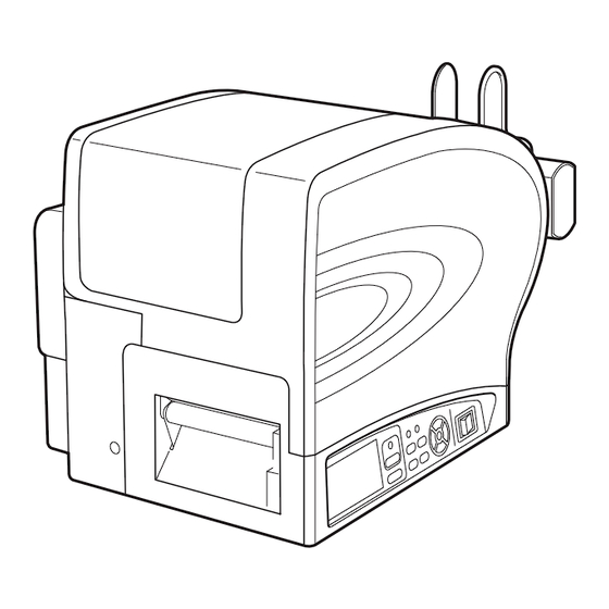
Page 9: Parts Identification
Section 1: Introduction 1.3 PARTS IDENTIFICATION Front view Main cover Media ejection slot Open this cover to load the media and ribbon. Opening for media output. Power (I/O) switch Operator panel Press this switch to turn the power on ( I ) or It consists of ten contact buttons and three off (O). - Page 10 Section 1: Introduction 1.3 PARTS IDENTIFICATION (cont’d) Back view Interface slot FUSE (T5AH 250V) holder Optional interface slot for connection to a host Used to hold a fuse which protect the printer PC. An option of RS-232C (High-speed) from unstable power supply surge. Use fuse interface board, IEEE1284 interface board, with rating, T5AH 250V only.
- Page 11 Section 1: Introduction 1.3 PARTS IDENTIFICATION (cont’d) Internal view when Main cover is opened (Front view) Ribbon take-up spindle (coreless) Head balance adjustment knob Used to wind up the used ribbon without using To adjust print head balance to obtain core.
- Page 12 Section 1: Introduction 1.3 PARTS IDENTIFICATION (cont’d) Internal view when Main cover is opened (Back view) Ribbon supply spindle Lid Latch lever Used to load the ribbon. Press the purple Lid Latch lever to open the hinged Lid Latch. Roll media guide Media feed-in guide Set to meet the size of the media used.
-
Page 13: Basic Specifications
Section 2: Basic Specifications BASIC SPECIFICATIONS 2.1 PRINTER BASIC SPECIFICATIONS TG308 / TG312 MODEL NAME PHYSICAL CHARACTERISTICS Width 11.18” (284 mm) Height 11.81” (300 mm) Depth 21.73” (552 mm) Weight 35.71 lbs. (16.2 Kg) POWER SUPPLY Input power voltage: AC 100V - 240V, +/-10% (Full range) Input Voltage Rated input voltage: AC 100V - 240V (Full range) At peak: 132W / 134VA (Print ratio 30%) - Page 14 Label: 0.006 to 0.01 in. (0.14 to 0.265 mm) Tag: 0.006 to 0.013 in. (0.157 to 0.33 mm) Thickness *For details on support for RFID tags, please contact your nearest SATO reseller or technical support center. Wind Direction Face-out/ Face-In...
- Page 15 Section 2: Basic Specifications INTERFACES 1) Plug-in Interface board (1 slot) 2) EXT (External) connector (for optional devices such as stacker and label Interface Board rewinder) 3) RS-232C D-sub 9-pin type (for keypad only) 1) RS-232C (High-Speed) I/F board 2) IEEE1284 (ECP/Compatible) I/F board 3) LAN I/F board Optional Plug-in interface 4) Wireless (LAN IEEE802.11b/g)/ Wired LAN I/F board...
- Page 16 Section 2: Basic Specifications CHARACTER FONT CAPABILITIES MATRIX FONTS 24 dots W x 24 dots H (Alphanumeric, symbols) 48 dots W x 48 dots H (Alphanumeric, symbols) 48 dots W x 48 dots H (Alphanumeric, symbols) TG308: 15 dots W x 22 dots H (Alphanumeric, symbols) OA Font (OCR-A) TG312: 22 dots W x 33 dots H (Alphanumeric, symbols) TG308: 20 dots W x 24 dots H (Alphanumeric, symbols)
- Page 17 Section 2: Basic Specifications CHARACTER FONT CAPABILITIES OUTLINE FONTS Alphanumeric characters and symbols CHARACTER CONTROL Magnification Expansion up to 12 x in either the vertical or horizontal Rotation 0°, 90°, 180° and 270° BARCODE CAPABILITIES UPC-A/E EAN-13/8 CODE39 CODE93 CODE128(UCC/EAN-128) (Character set: SET-A, SET-B, SET-C) CODABAR(NW-7) SATOC CODABAR(NW-7) Short CODARBAR(NW-7)
- Page 18 1) Large-size stacker (ST-TG3) 2) Label rewinder (RWG500) 3) RFID kit (with proprietary cutter) (HF-band, UHF-band, 2.45GHz) * Please check with SATO reseller on availability of the RFID kit. 4) Ribbon core adapter kit (comes with a core) 5) Keypad...
- Page 19 Section 2: Basic Specifications REGULATORY COMPLIANCE FCC15B /FCC15C (USA/Canada) Radio Standards R&TTE (EN300-330) (HF-band RFID, Europe) RFID(HF/ UHF) R&TTE (EN300-220-1/EN302-208-1) (UHF-band RFID, Europe) MIC (Korea) Packaging Drop Standard ISTA-2A Chromium: below 0.1% Lead: below 0.1% Mercury: below 0.1% Environmental (RoHS) Cadmium: below 0.01% Polybrominated Biphenyl (PBB): below 0.1% Polybrominated Diphenyl Ether (PBDE): below 0.1%...
-
Page 20: Optional Accessories Specifications
Section 2: Basic Specifications 2.2 OPTIONAL ACCESSORIES SPECIFICATIONS LARGE-SIZED STACKER SPECIFICATIONS Model name ST-TG3 Maximum stack height 5.9” (150 mm) (Paper thickness 0.01” (0.26 mm), approximately 500 tags) Tag feed speed 9.8” per second (250 mm/second) Tag only (Use of label is not acceptable) Media Type * Refer to the Consumable Specifications for more details. -
Page 21: Interface Specifications
Section 3: Interface Specifications INTERFACE SPECIFICATIONS This section presents the interface types and their specifications for the TG3 series printers. These specifications include detailed information to assist in the selection of the most appropriate method for the printer to interface with the host. The following information is presented in this section: •... -
Page 22: Rs232C High Speed Serial Interface
Section 3: Interface Specifications 3.2 RS232C HIGH SPEED SERIAL INTERFACE 3.2.1 RS-232C Serial Interface Card DIP SWITCH Settings The high-speed serial interface card (optional) contains DIP switches for controlling communication conditions. Determine what features are applicable to your setup, or desired setup, and adjust their respective DIP switches as applicable. - Page 23 Section 3: Interface Specifications 3.2 RS232C HIGH SPEED SERIAL INTERFACE (Cont’d) Notes: • Check the setting seal of the serial interface card. The correct settings may vary depending on the type and revision of the board. • The setting range of baud rate and protocol can be changed in the printer’s Interface Mode. See Section 4.7 Interface Mode for details.
- Page 24 Section 3: Interface Specifications 3.2 RS232C HIGH SPEED SERIAL INTERFACE (Cont’d) 3.2.3 Ready/Busy Ready / Busy is the hardware flow control method for the serial interface on the printer. Single item buffer and multi buffer can be toggled in the Interface Mode of the printer. When the print data (STX ESC+”A”~ ESC+”Z”...
- Page 25 Section 3: Interface Specifications 3.2 RS232C HIGH SPEED SERIAL INTERFACE (Cont’d) 3.2.4 X-ON/X-OFF This transmission protocol informs the host if the printer can receive data or not, by sending the “XON” (Hex 11H) or “XOFF” (Hex 13H) code. When the print data (STX ESC+”A”~ ESC+”Z” ETX) is sent from the host in the conditions below, received data may be incorrect.
-
Page 26: Ieee 1284 Parallel Interface
Section 3: Interface Specifications 3.3 IEEE 1284 PARALLEL INTERFACE The IEEE 1284 Interface on the printer complies with Centronics/ IEEE1284 standards.It will automatically detect the IEEE1284 signals and operate in the high speed mode. If it does not detect the IEEE1284 signals, it will operate in the standard Centronics mode, which is significantly slower. - Page 27 Section 3: Interface Specifications 3.3 IEEE 1284 PARALLEL INTERFACE (Cont’d) 3.3.2 Pin Assignments Pin assignment of each signal for the Centronics standard (Compatible Mode) is as follows. Note that the line connection for the IEEE1284 standard is based on the IEEE1284-B standard. PIN No.
- Page 28 Section 3: Interface Specifications 3.3 IEEE 1284 PARALLEL INTERFACE (Cont’d) 3.3.3 Input and Output Signals The details of each signal line for the Centronics standard (Compatible Mode) are as follows. Note that each signal line complies with the IEEE1284 standard. Pin No.
-
Page 29: Universal Serial Bus (Usb) Interface
Section 3: Interface Specifications 3.4 UNIVERSAL SERIAL BUS (USB) INTERFACE The Universal Serial Bus (USB) interface is a Plug-In Interface Module that can be installed by the user. It requires a driver (shipped with each printer that has the interface installed) that must be loaded on your PC and the PC must be configured to support USB peripherals using Windows 2000 or above. -
Page 30: Local Area Network (Lan) Ethernet
Section 3: Interface Specifications 3.5 LOCAL AREA NETWORK (LAN) ETHERNET A Local Area Network (LAN) interface is an optional Plug-In Interface Module that can be installed by the user. It requires a driver shipped with each printer that has the interface installed. The driver that must be loaded on the host computer and configured to run one of the supported network protocols using a 10/100BaseT LAN connection. - Page 31 Section 3: Interface Specifications 3.5 LOCAL AREA NETWORK (LAN) ETHERNET (Cont’d) 3.5.1 Basic Specifications (Cont’d) Communication setup The following communication settings are available in the Interface Mode of the printer. Item Setting range Protocol STATUS3 STATUS4 (Cyclic response mode) STATUS4 (ENQ response mode) STATUS5 IP address 0.0.0.0 ~ 255.255.255.255...
-
Page 32: Wireless Lan Ethernet
Section 3: Interface Specifications 3.6 WIRELESS LAN ETHERNET 3.6.1 Basic Specifications Interface connector LINK LED Status LED Wireless LED LINK LED Status LED Wireless LAN Interface board Cable type: For 10BASE-T and 100BASE-TX Cable length: 100m or less Link/Status LED Status LED lights up when establishing the LINK with Ethernet device or when receiving the packets. - Page 33 Section 3: Interface Specifications 3.6 WIRELESS LAN ETHERNET (Cont’d) 3.6.1 Basic Specifications (Cont’d) DSW is a maintenance switch to initialize the configuration saved on the wireless LAN board, to print the configuration, and to set wireless LAN communication mode. <Important> 1) Make sure to set all the DSW to “OFF”...
- Page 34 Section 3: Interface Specifications 3.6 WIRELESS LAN ETHERNET (Cont’d) 3.6.1 Basic Specifications (Cont’d) Wireless access Standard IEEE802.11b/11g Data transfer method (Auto switching) 11b : 11/5.5/2/1bps 11g : 54/48/36/24/18/12/11/9/6/5.5/2/1Mbps Communication distance Indoor (Max. 100m), Outdoor (Max. 240m) Use environment affects the communication distance. Frequency band 2.4GHz (2.412 ~ 2.4835GHz) Channel...
-
Page 35: Lan And Wireless Lan Ethernet Specifications
Section 3: Interface Specifications 3.7 LAN AND WIRELESS LAN ETHERNET SPECIFICATIONS 3.7.1 Software Specifications Protocol: TCP/IP Network layer: ARP, RARP, IP, ICMP Session layer: TCP, UDP Application layer: LPD, FTP, TELNET, BOOTP, DHCP, HTTP Notes • Send the print data by LPR and FTP of TCP/IP and dedicated socket protocol. •... - Page 36 97 : Reboot 98 : Quit setup 99 : Exit setup Please select(1-99)? For Wireless LAN Ethernet SATO Series WL Ver 1.0.0 TELNET server. SATO CORPORATION Copyright(C) 1999-2002 login: root 'root' user needs password to login password: User 'root' logged in No.
- Page 37 Section 3: Interface Specifications 3.7 LAN AND WIRELESS LAN ETHERNET SPECIFICATIONS (Cont’d) 3.7.6 Setting/Displayed Items The following table shows the settings and referable sections as well as various variables. TCP/IP related settings Variable identifier Setting range Default (Factory setting) TCP/ IP protocol ENABLE/ DISABLE ENABLE IP address...
-
Page 38: External Signal Interface (Ext)
Section 3: Interface Specifications 3.7 LAN AND WIRELESS LAN ETHERNET SPECIFICATIONS (Cont’d) 3.7.7 Wireless LAN Setting Variable identifier Setting range Default (Factory setting) SSID Optional alphanumeric character “NULL” (Up to 32 characters) Channel 1 ~ 14 Use WEP DISABLE/64 bits/128 bits DISABLE WEP Key Hexadecimal digit... - Page 39 Section 3: Interface Specifications 3.8 EXTERNAL SIGNAL INTERFACE (EXT) (Cont'd) 3.8.1 Basic Specifications Connector 14-pin external signal interface Input/Output circuit diagram High level : +2.4~+5.0V Signal level Low level : +0.0~+0.4V 3.8.2 Pin Assignments Electrical condition Signal name Description I / O Level (voltage, electric current [MAX])
- Page 40 Section 3: Interface Specifications This page is intentionally left blank Page 3-20 TG3 Series Service Manual...
-
Page 41: Operation And Configuration
Section 4: Operation and Configuration OPERATION AND CONFIGURATION Before using the printer, it is best to read this manual thoroughly first. Otherwise, you may disturb default settings upon which the instructional procedures in this manual are based. The printer may be manually configured via the ONLINE , FEED , CUTTER , EJECT , FUNCTION , PAPER and arrow buttons with the LCD display on the operator panel of printer. -
Page 42: Operator Panel
Section 4: Operation and Configuration 4.1 OPERATOR PANEL The operator panel located on the side, consists of three LED indicators, ten momentary contact buttons and one LCD display. There are eight adjustment potentiometers and a DIP switch located on the right bottom side when you are facing the printer. - Page 43 Section 4: Operation and Configuration 4.1 OPERATOR PANEL (Cont’d) • FUNCTION button Recalls the Mode Selection screen for selection of various function menus. Also returns the user to the Mode Selection screen from other menus. • PAPER button Pressing this button to select the paper type of the media loaded. •...
- Page 44 Section 4: Operation and Configuration 4.1 OPERATOR PANEL (Cont’d) List of Icons (Cont’d) [Error-related] Icon Description Displayed when detecting Label End Displayed when detecting Ribbon End Displayed when detecting Sensor Error Displayed when detecting Media Error Displayed when detecting Head Open Displayed when detecting electrical disconnection of print head Displayed when detecting Communication Error Displayed when detecting Receive Buffer Over...
-
Page 45: Operating Modes
Section 4: Operation and Configuration 4.2 OPERATING MODES The operating status of this printer can be set within one of the following modes: Normal mode (including Online/Offline modes) Adjustment screen Cancel Print Job mode Printer Setting mode: • User mode •... - Page 46 Section 4: Operation and Configuration 4.2 OPERATING MODES (Cont’d) The following flow chart provides a clear summary of all the modes and their access method. Power off Online state Switch Power to On “ I ” ONLINE button Offline state Menu screen FEED button...
- Page 47 Section 4: Operation and Configuration 4.2 OPERATING MODES (Cont’d) Power off FEED + Power on Test print Mode ONLINE + FEED + Power on Default setting Mode FUNCTION + Power on Power on Maintenance Mode Select SERVICE MODE + FEED button Service Mode Select FACTORY MODE +...
-
Page 48: Online And Offline Modes
Section 4: Operation and Configuration 4.3 ONLINE AND OFFLINE MODES The general and basic operation of the TG3 series printer is via the Normal mode, which consists of the ONLINE and Offline modes. 4.3.1 Online Mode Pressing the ONLINE button causes the printer to go ONLINE or Offline (Paper selection screen) alternately. - Page 49 Section 4: Operation and Configuration 4.3 ONLINE AND OFFLINE MODES (Cont’d) • The printer can feed a blank label/ tag when you press the FEED button. • The printer can be switched to CANCEL PRINT JOB modes when you press the FEED and ONLINE but- ton simultaneously.
-
Page 50: Adjustment Screen
Section 4: Operation and Configuration 4.4 ADJUSTMENT SCREEN The printer has a quick access to the Adjustment screen for setting the print position, stop position and the print darkness. These adjustments are in conjunction with the configuration adjustments done in the Service mode menu and the User mode menu. -
Page 51: Cancel Print Job Mode
Section 4: Operation and Configuration 4.5 CANCEL PRINT JOB MODE Offline mode Press ONLINE + FEED buttons Press / to select “YES” + FEED button 3 beep sound Online mode When the printer is Offline, pressing both the ONLINE and FEED buttons at the same time will switch the printer to CANCEL PRINT JOB mode. -
Page 52: User Mode
Section 4: Operation and Configuration 4.6 USER MODE The following settings are available in the User Mode. * Press button to select item or set the value accordingly. FEED The active arrow icons are displayed ONLINE button on the screen. button Displayed only when entry of PASSWORD is enabled... - Page 53 Section 4: Operation and Configuration 4.6 USER MODE (Cont’d) USER MODE Menu Description Adjusts the print speed that does not compromise print quality. Setting range is between 02 and 10 IPS (inches per second) with a increment of 01 IPS cyclically. The initial value is 6 IPS. This setting adjusts the print darkness of the print-out with reference to the set- ting of the DARKNESS in Adjustment screen.
-
Page 54: Interface Mode
Section 4: Operation and Configuration 4.7 INTERFACE MODE In this mode, you can set various parameters governing the use of interface cards. 4.7.1 Overview of Interface Mode Configurations * Press button to select item or set the value accordingly. The active arrow icons are displayed on the screen. - Page 55 Section 4: Operation and Configuration 4.7 INTERFACE MODE (Cont’d) INTERFACE MODE Menu Description This screen shows the connection setting of input device (Keypad). ENABLE : If the input device is connected, print data from the device will be valid. If the device is disconnected, print data received from the PC will be valid.
- Page 56 Section 4: Operation and Configuration 4.7 INTERFACE MODE (Cont’d) 4.7.2 Enabling Interface Card Configuration When INTERFACE BOARD SETTING is set to YES, the next display shows the connected interface card to be configured. Refer to the following flowcharts of the settings and LCD display menus available for LAN/ Wireless LAN, IEEE1284, USB and RS-232C interface cards.
- Page 57 Section 4: Operation and Configuration 4.7 INTERFACE MODE (Cont’d) LAN/Wireless LAN CONFIGURATION Menu Description This screen allows user to select the LAN/ Wireless LAN configurations based on either the setting on interface board or the setting of LCD. BOARD : Priority on current interface board settings Select BOARD and press FEED button will proceed directly to PROTOCOL setting.
- Page 58 Section 4: Operation and Configuration 4.7 INTERFACE MODE (Cont’d) LAN/Wireless LAN CONFIGURATION Menu Description Select the communication protocol. STATUS3, STATUS4 and STATUS5 are available for selection when LAN/ Wireless LAN interface boards are installed. The initial value is STATUS4. When STATUS3 is selected, the printer will proceed directly to IGNORE CR/LF menu.
- Page 59 Section 4: Operation and Configuration 4.7 INTERFACE MODE (Cont’d) Setting of IEEE1284 From INTERFACE BOARD SETTING screen * Press button to select item or set the value accordingly. FEED ONLINE The active arrow icons are displayed button button on the screen. * Pressing FUNCTION button on each screen will revert to INTERFACE MODE menu.
- Page 60 Section 4: Operation and Configuration 4.7 INTERFACE MODE (Cont’d) IEEE1284 CONFIGURATION Menu Description Setting receive buffer type. When MULTI and IEEE1284 are selected, the printer will proceed to PROTOCOL menu. When 1ITEM and IEEE1284 or CENTRONICS are selected, the printer will proceed to IEEE1284 ACK SIGNAL menu.
- Page 61 Section 4: Operation and Configuration 4.7 INTERFACE MODE (Cont’d) Setting of USB From INTERFACE * Press button to select BOARD SETTING item or set the value accordingly. screen The active arrow icons are displayed FEED on the screen. ONLINE button * Pressing FUNCTION button on each button screen will revert to INTERFACE...
- Page 62 Section 4: Operation and Configuration 4.7 INTERFACE MODE (Cont’d) Setting of RS-232C From INTERFACE BOARD SETTING screen FEED ONLINE button button Select BOARD + FEED button * Press button to select item or set the value accordingly. CONFIGURATION is set to BOARD The active arrow icons are displayed Select LCD + on the screen.
- Page 63 Section 4: Operation and Configuration 4.7 INTERFACE MODE (Cont’d) RS-232C CONFIGURATION Menu Description This screen allows user to select the RS-232C configurations based on either the setting on interface board (DIP switch) or the setting of LCD. BOARD : Priority on current interface board settings. Select BOARD and press FEED button will proceed directly to RECEIVE BUFFER or IGNORE CR/LF screen.
-
Page 64: Sembl Mode
Section 4: Operation and Configuration 4.7 INTERFACE MODE (Cont’d) RS-232C CONFIGURATION Menu Description Set item number check function. ENABLE : Item number check is ON DISABLE : Item number check is OFF The initial value is DISABLE. This screen is displayed only when PROTOCOL is set to STATUS5. Set BCC check function. -
Page 65: Advanced Mode
Section 4: Operation and Configuration 4.9 ADVANCED MODE Advanced Mode lets you configure the more advanced features of the printer hardware. Overview of Advanced Mode configurations Continued from SET CALENDAR screen as below FEED button ONLINE button FEED button ONLINE button Selectable languages Displayed only when entry of... - Page 66 Section 4: Operation and Configuration 4.9 ADVANCED MODE (Cont’d) During Offline mode, press FUNCTION button to display the operational icon menu. Press arrow buttons to select ADVANCED MODE. When ADVANCED MODE is displayed, press the FEED button to enter Advanced mode for adjustment. Note: PASSWORD may prompt on the display if SET PASSWORD is set to ON in the Service mode.
- Page 67 Section 4: Operation and Configuration 4.9 ADVANCED MODE (Cont’d) ADVANCED MODE Menu Description Specifying the printer motion right after changing the reference position by the <#> command. STOP : Pauses printing operation after changing the reference position. CONTINUE : Continues printing operation after changing the reference position.
- Page 68 Section 4: Operation and Configuration 4.9 ADVANCED MODE (Cont’d) ADVANCED MODE Menu Description Setting the display language on LCD. The display language differs by location that the printer was purchased. Destination Display language US (EX1) English only Europe (EX2) French, German, Spanish, Italian, Portuguese or English China (EX4)
- Page 69 Section 4: Operation and Configuration 4.9 ADVANCED MODE (Cont’d) ADVANCED MODE Menu Description LCD backlight is turned off for power saving when the printer is not operated for a specified period of time. Set the time between 00 and 15 MIN. This power saving function is disabled when it is 00 MIN, and the LCD back- light will be on constantly.
-
Page 70: Hex Dump Mode
Section 4: Operation and Configuration 4.10 HEX DUMP MODE HEX Dump Mode allows you to print the contents of the receive buffer in a hexadecimal format to allow the data stream to be examined for errors and troubleshooting. * Press button to select item or set the value accordingly. -
Page 71: Rfid User Mode
4.11 RFID USER MODE RFID User Mode lets you configure the RFID reading and writing features, as well as perform the test. (* Please check with SATO reseller on the availability of the RFID kit.) Overview of RFID User Mode configurations... - Page 72 Section 4: Operation and Configuration 4.11 RFID USER MODE (Cont’d) During Offline mode, press FUNCTION button to display the operational icon menu. Press arrow buttons to select the RFID USER MODE. The RFID USER MODE icon is displayed only when the RFID MODULE was ENABLE in the Maintenance mode.
- Page 73 Section 4: Operation and Configuration 4.11 RFID USER MODE (Cont’d) RFID USER MODE Menu Description Printing a slash on a tag when an RFID tag error occurred. YES : Prints a slash at the time of RFID tag error. NO : Not printing a slash at the time of RFID tag error. The initial value is NO.
- Page 74 Section 4: Operation and Configuration 4.11 RFID USER MODE (Cont’d) RFID USER MODE Menu Description Performing write test to RFID tag. Select YES and press FEED button to proceed the RFID tag writing test. If NO is selected, the printer goes to RFID TEST menu. The initial value is NO.
-
Page 75: Test Print Mode
Section 4: Operation and Configuration 4.12 TEST PRINT MODE Press FEED button + Switch Power to On “ I ” * Press button to select item or set the value accordingly. The active arrow icons are displayed on the screen. * Pressing FUNCTION button on each screen will revert to TEST PRINT menu. - Page 76 Section 4: Operation and Configuration 4.12 TEST PRINT MODE (Cont’d) The Test Print Mode offers seven different printer status labels for troubleshooting. Make sure the Power of the printer is turned off (O). While pressing the FEED button, switch the Power to On ( I ). TEST PRINT is displayed on the screen.
- Page 77 Section 4: Operation and Configuration 4.12 TEST PRINT MODE (Cont’d) TEST PRINT MODE Menu Description Setting ink roller motion during test print. NO : No ink roller action will be taken. YES : Ink roller action will be taken during test print. The initial value is NO.
- Page 78 Section 4: Operation and Configuration 4.12 TEST PRINT MODE (Cont’d) 4.12.1 Explanation of the contents of each piece of Configuration Test Print Below are Configuration Test print samples. Printed contents are subject to change without notice and the value depends on individual settings. 1) First piece -- Setting values in both User Mode and Advanced Mode, sensor information and DSW information will be printed.
- Page 79 Section 4: Operation and Configuration 4.12 TEST PRINT MODE (Cont’d) Item name to be printed Description Character Pitch or Character pitch setting. Char. Pitch For proportional pitch, “Proportional” will be printed. For fixed pitch, “Fixed” will be printed. Print Method Print method.
- Page 80 Section 4: Operation and Configuration 4.12 TEST PRINT MODE (Cont’d) Item name to be printed Description JP9 on CONT board (Main PCB). “0” must be selected for this setting. 2) Second piece -- Interface setting and setting values such as print position will be printed. Item name to be printed Description I/F-1...
- Page 81 Section 4: Operation and Configuration 4.12 TEST PRINT MODE (Cont’d) 3) Third piece -- RFID information will be printed. Note that this test print is available only when [RFID MODULE] is enabled. Item name to be printed Description MODEL NAME or Printer model name.
- Page 82 Section 4: Operation and Configuration 4.12 TEST PRINT MODE (Cont’d) Item name to be printed Description RFID Current Counter The number of succeeded/ failed RFID tag writes and the total tag count. Note that the count after reset or [CLEAR RFID COUNT] will be shown in this item.
- Page 83 Section 4: Operation and Configuration 4.12 TEST PRINT MODE (Cont’d) 4.12.3 Test Print of Head Check Print head will be checked and the check result will be printed. 4.12.4 Test Print of Head and Sensor Check Print head will be checked, and the check result and the sensor information will be printed. 4.12.5 Test Print of Memory Status The information of available memory size for user registration and free memory space will be printed.
- Page 84 Section 4: Operation and Configuration 4.12 TEST PRINT MODE (Cont’d) 4.12.7 Test Print List of Fonts The sample of fonts supported by this printer will be printed. Page 4-44 TG3 Series Service Manual...
- Page 85 Section 4: Operation and Configuration 4.12 TEST PRINT MODE (Cont’d) 4.12.8 Explanation of the contents of each pieces of Factory Test Print Below are Factory Test print samples (Large Size). Printed contents are subject to change without notice and the values depend on individual settings. First piece Second piece Page 4-45...
- Page 86 Section 4: Operation and Configuration 4.12 TEST PRINT MODE (Cont’d) Fourth piece Third piece 1) First piece -- Printer model name, firmware version, print head life expectancy, various serial numbers, and sensor information will be printed. Item name to be printed Description Model Name Printer model name.
- Page 87 Section 4: Operation and Configuration 4.12 TEST PRINT MODE (Cont’d) Item name to be printed Description Firm Date Created date of firmware. Print format is indicated by the last 2 digits of the year, month and day. Life Counter Printed life expectancy in “m” scale. Head Counter 1 Print head life expectancy in “m”...
- Page 88 Section 4: Operation and Configuration 4.12 TEST PRINT MODE (Cont’d) Item name to be printed Description Transmissive Sensor This information will be printed when transmissive sensor is Low [0.2<Lo<1.0] x.x(V) enabled. High [0.8<Hi-Lo] x.x(V) If “Low” is not [0.2 < Low < 1.0], “Low” will be indicated in reverse Slice Level Auto color.
- Page 89 Section 4: Operation and Configuration 4.12 TEST PRINT MODE (Cont’d) Item name to be printed Description Zero Slash The validity of slashed zero. When using a slashed zero, “On” will be printed. If not, “Off” will be printed. JIS Code JIS code setting.
- Page 90 Section 4: Operation and Configuration 4.12 TEST PRINT MODE (Cont’d) Item name to be printed Description Command Error The setting of command error display. “Error” will be printed if this setting is enabled. If not, “Warning” will be printed. Protocol Code Protocol code setting.
- Page 91 Section 4: Operation and Configuration 4.12 TEST PRINT MODE (Cont’d) Item name to be printed Description FROM2 CHECK SUM Extended memory, LCD data, UNICODE conversion table, check- sum value of TTF header area, and CODE39 barcode. Note that checksum value may change by destination. FROM3 CHECK SUM Checksum value of TTF/outline font and CODE39 barcode.
- Page 92 Section 4: Operation and Configuration 4.12 TEST PRINT MODE (Cont’d) 1) First piece -- Printer model name, firmware version, print head life expectancy, various serial numbers, sensor information, and DSW setting will be printed. Item name to be printed Description Model Printer model name.
- Page 93 Section 4: Operation and Configuration 4.12 TEST PRINT MODE (Cont’d) 2) Second piece -- Setting values in Service Mode, sensor information, VR (Potentiometer), offset values for each paper type will be printed. Item name to be printed Description Reflective Sensor This information will be printed when reflective sensor is enabled.
- Page 94 Section 4: Operation and Configuration 4.12 TEST PRINT MODE (Cont’d) 3) Third piece -- Setting values in both User Mode and Advanced Mode, sensor information, DSW setting and checksum will be printed. Item name to be printed Description Speed (Print Speed) Print speed.
- Page 95 Section 4: Operation and Configuration 4.12 TEST PRINT MODE (Cont’d) Item name to be printed Description Check The setting of calendar check. “Enabled” will be printed if calendar check is on. If not, “Disabled” will be printed. Note that this information will not be printed without installing the calendar IC.
-
Page 96: Default Setting Mode
Section 4: Operation and Configuration 4.13 DEFAULT SETTING MODE The printer can be reset to the default setting as in the factory preset. Press ONLINE + FEED button + Switch Power to On “ I ” * Press button to select item accordingly. - Page 97 Section 4: Operation and Configuration 4.13 DEFAULT SETTING MODE (Cont’d) DEFAULT SETTING MODE Menu Description This screen shows the completion of initialization and three beeps sound is heard. After this message is shown, power off the printer. 4.13.1 Table of Default Settings Default value Items TG308...
- Page 98 Section 4: Operation and Configuration 4.13 DEFAULT SETTING MODE (Cont’d) 4.13.1 Table of Default Settings (Cont’d) Default value Items TG308 TG312 ADVANCED MOD DARKNESS RANGE PRINT METHOD TRANSFER CHECK PITCH SIZE DISABLE COMMAND ERROR DISPLAY AUTO ONLINE ADJUST FEED ACTION CONTINUE HEAD CHECK DISABLE...
-
Page 99: Maintenance Mode
Section 4: Operation and Configuration 4.14 MAINTENANCE MODE In Maintenance mode, you can further access Service mode, Factory mode and RFID mode for more printer configuration. Press FUNCTION + button + Switch Power to On “ I ” Press button + Switch Power to On “... -
Page 100: Service Mode
Section 4: Operation and Configuration 4.15 SERVICE MODE In SERVICE MODE menu, you can program various dimensional settings of the printer. Press arrow buttons to select SERVICE LEVEL, PITCH OFFSET, CUT OFFSET, BACKFEED OFFSET, LOADING OFFSET or SETTING, and then press FEED button to enter the selected mode. Refer to the following flowcharts of the settings and LCD display menus available in SERVICE MODE. - Page 101 Section 4: Operation and Configuration 4.15 SERVICE MODE (Cont’d) SENSOR LEVEL MODE Menu Description Displaying the current level of I-mark sensor on the upper part of the display. Adjust the sensor level offset with arrow buttons. This offset determined how soon the sensor responds to an oncoming I-Mark. The adjustment range is between 0 and 63 and is shown on the bottom line of the display.
- Page 102 Section 4: Operation and Configuration 4.15 SERVICE MODE (Cont’d) 4.15.2 Pitch Offset adjustment in Service Mode Select PITCH OFFSET + FEED button ONLINE button FUNCTION * Press button to select button item or set the value accordingly. The active arrow icons are displayed on the screen.
- Page 103 Section 4: Operation and Configuration 4.15 SERVICE MODE (Cont’d) 4.15.3 Cut Offset adjustment in Service Mode Select CUT OFFSET + FEED button ONLINE button FUNCTION * Press button to select button item or set the value accordingly. The active arrow icons are displayed on the screen.
- Page 104 Section 4: Operation and Configuration 4.15 SERVICE MODE (Cont’d) 4.15.4 Backfeed Offset adjustment in Service Mode Select BACKFEED OFFSET + FEED button ONLINE button FUNCTION * Press button to select button item or set the value accordingly. The active arrow icons are displayed on the screen.
- Page 105 Section 4: Operation and Configuration 4.15 SERVICE MODE (Cont’d) 4.15.5 Loading Offset adjustment in Service Mode Select LOADING OFFSET + FEED button ONLINE button FUNCTION * Press button to select button item or set the value accordingly. The active arrow icons are displayed on the screen.
- Page 106 Section 4: Operation and Configuration 4.15 SERVICE MODE (Cont’d) 4.15.6 Overview of Setting menu in Service Mode * Press button to select item or set the value accordingly. Select SETTING + The active arrow icons are displayed FEED button on the screen. ONLINE button FUNCTION button...
- Page 107 Section 4: Operation and Configuration 4.15 SERVICE MODE (Cont’d) SETTING MODE Menu Description Displaying the set values of volumes (VR) on the main PCB of the printer. PITCH : Shows the value of print offset volume. OFFSET : Shows the value of cut offset volume. DARKNESS : Shows the value of darkness volume.
-
Page 108: Factory Mode
Section 4: Operation and Configuration 4.16 FACTORY MODE In Factory mode, you can reset a counter in the printer, view the value of a counter, adjust LCD brightness or darkness, enter your serial number, and specify characteristics of a test print. Press FUNCTION + button * Press... - Page 109 Section 4: Operation and Configuration 4.16 FACTORY MODE (Cont’d) Continued from INTERFACE BOARD * Press button to select REVISION screen on the previous page item or set the value accordingly. FEED button The active arrow icons are displayed ONLINE button on the screen.
- Page 110 Section 4: Operation and Configuration 4.16 FACTORY MODE (Cont’d) FACTORY MODE Menu Description Resetting a counter in the printer. The 6 items below are selectable. NONE....No reset ALL......Printer settings and all of the counters are reset. COUNTERS..Reset all of the counters. LIFE.....Reset only life counter.
- Page 111 Section 4: Operation and Configuration 4.16 FACTORY MODE (Cont’d) FACTORY MODE Menu Description Use this to enter the revision number of the main PCB. Use the arrow buttons to move the cursor. Enter the revision number with the arrow buttons, and press FEED . The initial value is 0.0.
- Page 112 Section 4: Operation and Configuration 4.16 FACTORY MODE (Cont’d) FACTORY MODE Menu Description Adjust print and cut positions. Press arrow buttons to enter set values and press arrow buttons to toggle between PITCH POSITION and OFFSET POSITION setting. For each, the setting range is ± 0.15 in. (± 3.75 mm), and it is adjustable by 0.01 in.
-
Page 113: Rfid Mode
4.17 RFID MODE After installing the RFID module to the printer, you need to activate the RFID module through the printer configuration. (* Please check with SATO reseller on the availability of the RFID kit.) * Press button to select item or set the value accordingly. - Page 114 Section 4: Operation and Configuration 4.17 RFID MODE (Cont’d) RFID MODE Menu Description Setting RFID function. ENABLE : RFID module is activated. RFID USER MODE icon will display on the operational menu when FUNCTION button is pressed in offline mode. DISABLE : RFID function is OFF.
-
Page 115: Download Mode
Section 4: Operation and Configuration 4.18 DOWNLOAD MODE This download feature allows the operator to download data (firmware, font/logo, True type font), from the host computer and write in the Flash ROM memory. When downloading is complete, the LCD screen will return to the original display after three seconds. - Page 116 Section 4: Operation and Configuration 4.18 DOWNLOAD MODE (Cont’d) Make sure the Power of the printer is turned off (O). While pressing the arrow button, switch the Power to On ( I ). The printer enters DOWNLOAD READY mode. Using MS-Prompt command, send in the data for downloading from the host computer to the printer. DOWNLOAD MODE Menu Description...
- Page 117 Section 4: Operation and Configuration 4.18 DOWNLOAD MODE (Cont’d) DOWNLOAD MODE Menu Description Completion of font data registry. Emitting three short beeps when font registry is completed. Goes to DOWNLOAD READY screen automatically three seconds later. Completion of font data deletion. Emitting three short beeps when font delete is completed.
-
Page 118: Boot Download Mode
Section 4: Operation and Configuration 4.19 BOOT DOWNLOAD MODE Press FUNCTION + button + Switch Power to On “ I ” Start downloading Received download data Finished writing download data Download data verified * 3 short beeps are heard when the boot download is completed. - Page 119 Section 4: Operation and Configuration 4.19 BOOT DOWNLOAD MODE (Cont’d) BOOT DOWNLOAD MODE Menu Description The printer is waiting to receive data. Firmware data will be received from the PC and written to main ROM. (1) Firmware data The printer is downloading data. The gauge shown on the lower portion of the screen indicates downloading status.
- Page 120 Section 4: Operation and Configuration This page is intentionally left blank Page 4-80 TG3 Series Service Manual...
-
Page 121: Troubleshooting
Section 5: Troubleshooting TROUBLESHOOTING If you are unable to produce printouts on the TG3 series printer, use this section to make sure the basics have been checked, before deciding you are unable to proceed any further. The section is divided into four parts: •... -
Page 122: Error Signal Troubleshooting
ERROR DISPLAY BUZZER ERROR CONDITION CORRECTIVE ACTION MACHINE ERROR ONLINE: 1 Long 1) Defective PCB board 1) Consult your SATO reseller or Beep technical support center to replace the PCB board ERROR: To clear error: Power Off FLASHROM ERROR ONLINE:... - Page 123 HEAD ERROR ONLINE: 1 long 1) Print head damage 1) Replace Print head or consult Beep your SATO reseller or technical • Error will be detected support center ERROR: only when head check is enabled To clear error: Hold down...
- Page 124 Section 5: Troubleshooting ERROR DISPLAY BUZZER ERROR CONDITION CORRECTIVE ACTION BCC CHECK ERROR ONLINE: 3 short 1) BCC that is added to send 1) Check host data and Beeps data (for 1 item) differs. communication settings ERROR: To clear error: Press Blinks ONLINE button or cancel job.
- Page 125 Section 5: Troubleshooting ERROR DISPLAY BUZZER ERROR CONDITION CORRECTIVE ACTION MEDIA ERROR ONLINE: 3 short 1) Specified media size is 1) Set the specified size media Beeps not correct. ERROR: To clear error: Head open Blinks and then close COMMAND ERROR ONLINE: 3 short 1) Detecting improper...
- Page 126 Section 5: Troubleshooting 5.1 ERROR SIGNAL TROUBLESHOOTING (Cont’d) 5.1.2 More information about Command Error Printer Motion when detecting Command Error When COMMAND ERROR DISPLAY is set to YES in Advanced Mode, the information of a command in which a command error was detected will be shown at the bottom of the screen, and the print operation will be paused.
-
Page 127: Warning Message
Section 5: Troubleshooting 5.1 ERROR SIGNAL TROUBLESHOOTING (Cont’d) 5.1.3 Warning Message Note that the printer will continue issuing tag/label while detecting a warning message. WARNING DISPLAY BUZZER ERROR CONDITION CORRECTIVE ACTION RIBBON NEAR END ONLINE: 1) Remaining ribbon length 1) Change ribbon. becomes short. -
Page 128: Troubleshooting Flowchart
Section 5: Troubleshooting 5.2 TROUBLESHOOTING FLOWCHART When a problem occurs, the solution can be easily traced using the following troubleshooting flowcharts. For each problem, the chart shows its symptoms, probable causes, and suggested corrective actions. 5.2.1 Power Problem Category Symptoms Causes Remedy Maintenance... - Page 129 Section 5: Troubleshooting 5.2 TROUBLESHOOTING FLOWCHART (Cont’d) 5.2.2 Feed Problem Category Symptoms Causes Remedy Maintenance Printer Set the paper Is paper set does not Feed correctly feed paper Set the PAPER Is sensor sensor displayed selection on LCD correctly Is platen Clean the roller platen roller...
- Page 130 Section 5: Troubleshooting 5.2 TROUBLESHOOTING FLOWCHART (Cont’d) 5.2.2 Feed Problem (Cont’d) Category Symptoms Causes Remedy Maintenance Paper does Set the PAPER Is sensor not stop at the Feed sensor displayed selection specified on LCD correctly position Adjust pitch Is sensor level sensor Refer to 6.9 Adjusting and...
- Page 131 Section 5: Troubleshooting 5.2 TROUBLESHOOTING FLOWCHART (Cont’d) 5.2.3 Print Problems Category Symptoms Causes Remedy Maintenance Is interface No printing Connect Printing cable connec- motion interface cable tion OK? Re-entry Is data input of data Check feeding condition Refer to 5.2.2 Feed Problem Blank label Re-entry...
- Page 132 Section 5: Troubleshooting 5.2 TROUBLESHOOTING FLOWCHART (Cont’d) 5.2.3 Print Problems (Cont’d) Category Symptoms Causes Remedy Maintenance Abnormal Print is too Adjust print print dark darkness Refer to 6.12 Adjusting Print Darkness Is print Print is too Adjust print darkness set light darkness properly?
- Page 133 Section 5: Troubleshooting 5.2 TROUBLESHOOTING FLOWCHART (Cont’d) 5.2.3 Print Problems (Cont’d) Category Symptoms Causes Remedy Maintenance Misaligned print Re-entry Abnormal start position Is data input (Vertical- of data print direction) Set the PAPER Is the correct sensor displayed sensor on LCD correctly selected? Adjust pitch offset...
- Page 134 Section 5: Troubleshooting 5.2 TROUBLESHOOTING FLOWCHART (Cont’d) 5.2.3 Print Problems (Cont’d) Category Symptoms Causes Remedy Maintenance Ribbon Set label Abnormal Is label set wrinkle print correctly correctly? Set ribbon Is ribbon set correctly correctly? Is thermal Adjust thermal head position head position Refer to 6.16 Adjusting Print...
- Page 135 Section 5: Troubleshooting 5.2 TROUBLESHOOTING FLOWCHART (Cont’d) 5.2.4 Media Problem Category Symptoms Causes Remedy Maintenance Set label or Media Is media set Media label guide meandering correctly? correctly Is thermal Adjust thermal head position head position Refer to 6.16 Adjusting Print Head Position Is thermal Adjust thermal...
- Page 136 Section 5: Troubleshooting 5.2 TROUBLESHOOTING FLOWCHART (Cont’d) 5.2.5 Cutter Problems Category Symptoms Causes Remedy Maintenance Is cutter Replace Cutter Adjust cutter Media is Cutter sensor sensor not cut off Refer to 6.10 Refer to 7.24 Adjusting Cutter Replacing Cutter Sensors PCB Board Is circle Replace Cutter...
-
Page 137: Interface Troubleshooting
Click on System within the new window. Click on the Device Manager tab. Ensure that the View Device By Type is checked. Scroll to SATO-USB Device and ensure that errors do not exist. Reinstall as required. Reboot the PC and the printer. Page 5-17... -
Page 138: Test Print Troubleshooting
Section 5: Troubleshooting LAN ETHERNET INTERFACE TROUBLESHOOTING STEP Ensure the interface has been correctly configured. Wait two minutes and run self-test to verify. If a test label does not print, there may be a hardware problem. Ensure the cable and its ports are not defective. Ensure that a faulty print server or other protocol related scenarios are not creating a queue setup issue. -
Page 139: Adjustment Procedures
Section 6: Checks and Adjustment Procedures ADJUSTMENT PROCEDURES This section provides instructions for electrical and mechanical adjustments to the printer. Regular maintenance in making adjustments to reset the printer to factory specifications will ensure optimum performance of your printer. The Adjustment Procedure describe in this section are as follows. •... -
Page 140: Functional Structure Of Main Pcb
Section 6: Checks and Adjustment Procedures 6.1 FUNCTIONAL STRUCTURE OF MAIN PCB There are ten potentiometers (VRs) and a DIP switch (DSW) on the Main PCB for functional adjustment. These are explained as below. VR10 DSW (viewing from top) CONT PCB 1) Default DSW (Dip switch) setting Model Head density... - Page 141 Section 6: Checks and Adjustment Procedures 6.1 FUNCTIONAL STRUCTURE OF MAIN PCB (Cont’d) 2) VRs (Potentiometers) Name Functions F.OFFSET Adjusts factory offset PITCH Adjusts print start position OFFSET Adjusts cutting position DARK Adjusts print darkness Adjusts I-Mark sensor level Adjusts Gap sensor level S.HOLE Adjusts side hole sensor level DISP...
-
Page 142: Checking The Direct-Current Power Supply
This checking procedure enables checking various direct current voltages of the Main PCB (CONT board) . These checking activities require the use of a multimeter and may be performed with or without the assistance of the SATO Test Module . The test module is a purchase option. Required Tools: •... - Page 143 Section 6: Checks and Adjustment Procedures 6.2 CHECKING THE DIRECT-CURRENT POWER SUPPLY (Cont’d) Criteria Table of normal performance values: +5.0V +4.8V to +5.2V (CH3A - CH1A) +1.7V +1.6V to +1.8V (CH4A - CH1A) +3.3V +3.3V: +3.1V to +3.5V (CH5A - CH1A) +24.0V +24.0V: +23.5V to +25.5V (CH6A - CH1A) CHK Connector...
-
Page 144: Counter Clear Mode
Section 6: Checks and Adjustment Procedures 6.3 COUNTER CLEAR MODE The printer has integrated counters to measure the accumulative activity of some features. These includes a life counter, a head counter, a cut counter and a dispense counter. In this mode, you can reset these counters to zero. Enter to MAINTENANCE MODE, select FACTORY MODE and then press FEED button. -
Page 145: To Perform Factory Test Print
Section 6: Checks and Adjustment Procedures 6.5 TO PERFORM FACTORY TEST PRINT After changes of parameter settings or replace of parts, it is advisable to perform Factory test print. There are two ways to perform Factory Test Print mode. 6.5.1 To access through TEST PRINT MODE menu. You may direct access the Test Print Mode by turning the Power on while pressing the FEED button. - Page 146 Section 6: Checks and Adjustment Procedures 6.6 ADJUSTING PITCH OFFSET (Cont’d) Use the micro driver to turn the potentiometer, VR2 (PITCH) , located on the Main PCB (CONT) , to the right or left to adjust the value, and then press the FEED button to save the value. The adjustment range is ±0.15”...
-
Page 147: Adjusting Cut Offset
Section 6: Checks and Adjustment Procedures 6.6 ADJUSTING PITCH OFFSET (Cont’d) 6.6.3 To adjust the Pitch Offset from the Adjustment mode When the printer is Offline, pressing both the FUNCTION and arrow but- tons at the same time will switch the printer to Adjustment mode. The PITCH POSITION screen is displayed. - Page 148 Section 6: Checks and Adjustment Procedures 6.7 ADJUSTING CUT OFFSET (Cont’d) 6.7.2 To adjust the Cut Offset base on media used Enter to MAINTENANCE MODE, select SERVICE MODE and then press FEED button. Refer to Section 4.14 Maintenance Mode for more details. Press the arrow buttons to select CUT OFFSET on the SERVICE MODE screen, and press the FEED button.
-
Page 149: Adjusting Backfeed Offset
Section 6: Checks and Adjustment Procedures 6.8 ADJUSTING BACKFEED OFFSET This setting adjusts the backfeed distance after or before a print out. Enter to MAINTENANCE MODE, select SERVICE MODE and then press FEED button. Refer to Section 4.14 Maintenance Mode for more details. Press the arrow buttons to select BACKFEED OFFSET on the SERVICE MODE screen, and press the FEED button. -
Page 150: Adjusting And Checking Sensors
Section 6: Checks and Adjustment Procedures 6.9 ADJUSTING AND CHECKING SENSORS In Service Mode, we can check the media sensor condition as well as to calibrate the media sensor level for the optimum performance. Enter to MAINTENANCE MODE, select SERVICE MODE and then press FEED button. - Page 151 Section 6: Checks and Adjustment Procedures 6.9 ADJUSTING AND CHECKING SENSORS (Cont’d) Explanation on the details of the Sensor Level screen • The number shown next to the sensor name indicates sensor level. sensor • ADJUST LEVEL indicates the number of taps for electric volume. level Increasing or decreasing the number of taps changes the resistance value of Adjust...
- Page 152 NOTE: Measure the sensor level directly in the Maintenance mode only. This is because the sensor protection (measurement to prolong operating life) is enabled in the ONLINE mode. These checking activities require the use of a multimeter and may be performed with or without the assistance of the SATO Test Module . (IM) Test...
- Page 153 Section 6: Checks and Adjustment Procedures 6.9 ADJUSTING AND CHECKING SENSORS (Cont’d) Relocate the media so that the I-Mark is oriented over the sensor directly. Note: To stabilize the sensor level, make sure the print head assembly is locked and the media is threaded cor- rectly.
- Page 154 (measurement to prolong operating life) is enabled in the ONLINE mode. These checking activities require the use of a multimeter and may be performed with or without the assistance of the SATO Test Module . Page 6-16 TG3 Series Service Manual...
- Page 155 Section 6: Checks and Adjustment Procedures 6.9 ADJUSTING AND CHECKING SENSORS (Cont’d) (GAP) Test CONT PCB Module Set Dial to 5 Connect [ + ] to point 2B Connect [ - ] Top view of probe here Connector Connect [ + ] probe here Connect [ - ] to point 1A Remove the side cover to reveal the Main PCB (CONT board) .
- Page 156 Section 6: Checks and Adjustment Procedures 6.9 ADJUSTING AND CHECKING SENSORS (Cont’d) 6.9.3 Side hole Sensor Sensitivity Adjustment This sensor adjustment regulates penetrating ability for media referencing. The side hold sensor is located at the Lid latch. To adjust the Side hole sensor level with the Operator Panel Note: This calibration is only for fine tuning.
- Page 157 NOTE: Measure the sensor level directly in the Maintenance mode only. This is because the sensor protection (measurement to prolong operating life) is enabled in the ONLINE mode. These checking activities require the use of a multimeter and may be performed with or without the assistance of the SATO Test Module . (S.HOLE) Test...
- Page 158 Section 6: Checks and Adjustment Procedures 6.9 ADJUSTING AND CHECKING SENSORS (Cont’d) 6.9.4 Edge Sensor Sensitivity Adjustment This sensor adjustment regulates penetrating ability for media referencing. The edge sensor is located next to I-Mark sensor. To adjust the Edge sensor level with the Operator Panel Note: This calibration is only for fine tuning.
- Page 159 NOTE: Measure the sensor level directly in the Maintenance mode only. This is because the sensor protection (measurement to prolong operating life) is enabled in the ONLINE mode. These checking activities require the use of a multimeter and may be performed with or without the assistance of the SATO Test Module . (KADO.R) Test...
- Page 160 NOTE: Measure the sensor level directly in the Maintenance mode only. This is because the sensor protection (measurement to prolong operating life) is enabled in the ONLINE mode. These checking activities require the use of a multimeter and may be performed with or without the assistance of the SATO Test Module . (J.HOLE) Test...
- Page 161 Section 6: Checks and Adjustment Procedures 6.9 ADJUSTING AND CHECKING SENSORS (Cont’d) When using the optional Test Module for checking, connect the optional Test Module to the CHK connector as shown above. Set the digital multimeter to direct-current voltage mode. Connect [+] probe to “SIG”...
-
Page 162: Adjusting Cutter Sensors
Section 6: Checks and Adjustment Procedures 6.10 ADJUSTING CUTTER SENSORS The cutter unit equipped with another set of pitch sensor which works independently to detect the media for cutting. 6.10.1 To adjust Gap/ Center hole sensor Ensure the printer power is turned off. Detach the cutter unit without disconnecting the connector. - Page 163 Section 6: Checks and Adjustment Procedures 6.10 ADJUSTING CUTTER SENSORS (Cont’d) To calibrate the Gap/ Center hole sensor level with the potentiometer NOTE: Measure the sensor level directly in the Maintenance mode only. This is because the sensor protection (measurement to prolong operating life) is enabled in the ONLINE mode. The potentiometer of cutter unit is used for adjusting the cutter sensor.
- Page 164 Section 6: Checks and Adjustment Procedures 6.10 ADJUSTING CUTTER SENSORS (Cont’d) 6.10.2 To adjust I-Mark sensor Ensure the printer power is turned off. Detach the cutter unit without disconnecting the connector. First, lift up the Main cover , unscrew the shaft that holds the cutter unit in place, removed the shaft and set aside.
- Page 165 Section 6: Checks and Adjustment Procedures 6.10 ADJUSTING CUTTER SENSORS (Cont’d) To calibrate the I-Mark sensor level with the potentiometer NOTE: Measure the sensor level directly in the Maintenance mode only. This is because the sensor protection (measurement to prolong operating life) is enabled in the ONLINE mode. The potentiometer of cutter unit is used for adjusting the cutter sensor.
- Page 166 Section 6: Checks and Adjustment Procedures 6.10 ADJUSTING CUTTER SENSORS (Cont’d) 6.10.3 To adjust Edge sensor Ensure the printer power is turned off. Detach the cutter unit without disconnecting the connector. First, lift up the Main cover , unscrew the shaft that holds the cutter unit in place, removed the shaft and set aside.
- Page 167 Section 6: Checks and Adjustment Procedures 6.10 ADJUSTING CUTTER SENSORS (Cont’d) To calibrate the Edge sensor level with the potentiometer NOTE: Measure the sensor level directly in the Maintenance mode only. This is because the sensor protection (measurement to prolong operating life) is enabled in the ONLINE mode. EDGE The potentiometer of cutter unit is used for adjusting the cutter sensor.
- Page 168 Section 6: Checks and Adjustment Procedures 6.10 ADJUSTING CUTTER SENSORS (Cont’d) 6.10.4 To adjust circle cutter position sensor Ensure the printer power is turned off. Detach the cutter unit without disconnecting the connector. First, lift up the Main cover , unscrew the shaft that holds the cutter unit in place, removed the shaft and set aside.
- Page 169 Section 6: Checks and Adjustment Procedures 6.10 ADJUSTING CUTTER SENSORS (Cont’d) Turn on the power and use a micro driver to adjust the VR1 potentiometer of the cutter position sensor until the readings of the multimeter satisfied the following condition. With the white slider positioned at the SEN1 , adjust the VR1 potentiometer until the reading of the multim- eter is +0.5V or below.
-
Page 170: Sensor Checks
Section 6: Checks and Adjustment Procedures 6.11 SENSOR CHECKS 6.11.1 To check Ribbon End Note: There is no need to perform step 2 to step 4 if the printer is still in the default Thermal Trans- fer mode. Press the ONLINE button in online mode state to go offline. Press the FUNCTION button to enter the Mode Selection screen. -
Page 171: Adjusting Print Darkness
Section 6: Checks and Adjustment Procedures 6.12 ADJUSTING PRINT DARKNESS 6.12.1 To adjust the Print Darkness in Adjustment Mode Press the ONLINE button in online mode state to go offline. Pressing both the FUNCTION and the arrow buttons at the same time will switch the printer to Adjustment mode.The PITCH POSITION screen is displayed. -
Page 172: Adjusting Lcd Brightness
Section 6: Checks and Adjustment Procedures 6.13 ADJUSTING LCD BRIGHTNESS 6.13.1 To adjust the LCD screen Brightness in Normal Mode In Normal mode (ONLINE or Offline), press the arrow buttons repeatedly to adjust the LCD Brightness. 6.13.2 To adjust the LCD screen Brightness in Factory Mode Enter to MAINTENANCE MODE, select FACTORY MODE and then press FEED button. -
Page 173: Calendar Setting
Section 6: Checks and Adjustment Procedures 6.15 CALENDAR SETTING Note: The calendar setting is available only when the calendar IC is installed in the printer. Enter to ADVANCED MODE, and press FEED button repeatedly until SET CALENDAR is displayed. Refer to Section 4.9 Advanced Mode for more details. -
Page 174: Adjusting Print Head Position
Section 6: Checks and Adjustment Procedures 6.16 ADJUSTING PRINT HEAD POSITION Print head balance and alignment have a direct impact on print quality. The print head must be parallel with the platen roller for the printed image to be consistent in quality across the label. 6.16.1 Print Head Balance Adjustment (Left and Right sides) Print head balance is the equalization of pressure against the platen roller from one end to the opposite. - Page 175 Section 6: Checks and Adjustment Procedures 6.16 ADJUSTING PRINT HEAD POSITION (Cont’d) Fine Tuning of Head Balance with the Adjustment Screw Adjust the screw of head balance plate for optimal printing position. Loosen the screw: Print on the engine frame side gets darker. Paper leans to the engine frame side. Tighten the screw: Print on the head lock lever side gets darker.
- Page 176 Section 6: Checks and Adjustment Procedures 6.16 ADJUSTING PRINT HEAD POSITION (Cont’d) 6.16.2 Print Head Alignment Print head position has a direct impact on print quality. The print head must be parallel with the platen roller for the printed image to be consistent across the label. To adjust Print Head Alignment with the knob Unlatch the print head and locate the purple knob beside the head lock lever .
- Page 177 Section 6: Checks and Adjustment Procedures 6.16 ADJUSTING PRINT HEAD POSITION (Cont’d) Head BR Head ASSY mounting screw Removed head BR Head BR and fixation screws Head BR Thermal head Page 6-39 TG3 Series Service Manual...
-
Page 178: Adjusting Feed Roller
Section 6: Checks and Adjustment Procedures 6.17 ADJUSTING FEED ROLLER Required tool: Phillips head screwdriver, Spanner 5.5 Let the feed roller run after setting the label or tag. Loosen the fixation screw of adjust collar for lid latch. Turn the adjust collar up and down to adjust the paper slack. Tighten up the fixation screw to fix the adjusted collar position. -
Page 179: Adjusting Ribbon Tension
Section 6: Checks and Adjustment Procedures 6.18 ADJUSTING RIBBON TENSION 6.18.1 Ribbon guide adjustment If the print ribbon is not spread smoothly over the print head when it makes contact with the media, print voids will occur at the point of the ribbon fold. Typically, this is the result of the axis of the ribbon spindle/ print head/ ribbon guide not being perfectly parallel. - Page 180 Section 6: Checks and Adjustment Procedures 6.18 ADJUSTING RIBBON TENSION (Cont’d) 6.18.2 Ribbon shaft plates adjustment The adjustment of the ribbon shaft plates is to compensate for the axis deviations of the ribbon spindle causing the ribbon wrinkles. ATTENTION: ADJUST THE RIBBON TENSION BY USING RIBBON GUIDE OF PREVIOUS PROCE- DURE.
-
Page 181: Adjusting Timing Belt Tension
Section 6: Checks and Adjustment Procedures 6.19 ADJUSTING TIMING BELT TENSION This printer model incorporates the use of dual timing belts that transfers torque from the drive motor to the platen motor. Required tool: Phillips head screwdriver Switch off the printer and disconnect power supply cord. Remove the main cover, left housing cover and the top left housing cover to gain access to the internal (electrical and mechanism) hardware. -
Page 182: Adjusting Cutter Motor Timing Belt Tension
Section 6: Checks and Adjustment Procedures 6.20 ADJUSTING CUTTER MOTOR TIMING BELT TENSION Required tool: Phillips head screwdriver, and tension gauge 2.20 pounds (1kg) Switch off the printer and disconnect power supply cord. Lift up the Main cover, unscrew the shaft that holds the cutter unit in place, removed the shaft and set aside. -
Page 183: Adjusting Optional Stacker Motor Timing Belt Tension (St-Tg3)
Section 6: Checks and Adjustment Procedures 6.21 ADJUSTING OPTIONAL STACKER MOTOR TIMING BELT TENSION (ST-TG3) Required tool: Phillips head screwdriver, tension gauge 2.20 pounds (1kg) Measurement : Place the tension gauge on the timing belt nearly in the middle of motor pulley shaft and feed roller pulley shaft. -
Page 184: Adjusting Optional Stacker Timing Belt Tension (St-Tg3)
Section 6: Checks and Adjustment Procedures 6.22 ADJUSTING OPTIONAL STACKER TIMING BELT TENSION (ST-TG3) Required tool: Phillips head screwdriver Measurement : Detach the Cover (LH) by removing the five screws. Access and remove the four screws that hold the Cover (RH) to the center frame . Turn the printer around to access the front of the stacker. -
Page 185: Replacement Procedures
Section 7: Replacement Procedures REPLACEMENT PROCEDURES This unit provides in-depth instruction on all primary component and assembly replacement, in addition to most secondary components. Be sure to observe all the precautions or warning notes. The Replacement Procedures described in this section are as follows. •... -
Page 186: Removal Of Housing Cover
Section 7: Replacement Procedures 7.1 REMOVAL OF HOUSING COVER Before remove the casing of the printer, turn Off the power of the printer. Disconnect all the cables attached to the printer. If you need to remove the CONT board (main PCB), disconnect the attached interface card. 7.1.1 To remove Main cover Lift up the main cover . -
Page 187: Replacing Print Head
Section 7: Replacement Procedures 7.2 REPLACING PRINT HEAD If the print head becomes damaged or worn, it can be easily removed and replaced without having to make critical adjustments. Please wear protective gloves to avoid contaminating the sensitive print head surface. Before replacing the print head, check the head counter values by printing a test pattern. - Page 188 Section 7: Replacement Procedures 7.2 REPLACING PRINT HEAD (cont’d) Reconnect two wiring harnesses (2, 3) to replacement print head (4). Note: Each of the printer’s wiring harness connectors are different to ensure proper matching. Position the print head (4) so that the center screw hole is aligned and the alignment pins are aligned with the alignment holes on top of the print head.
-
Page 189: Replacing Platen Roller
Section 7: Replacement Procedures 7.3 REPLACING PLATEN ROLLER The printer’s platen roller is considered to be a high-wear component due to constant treading of the print media and ribbon stock against its contact surface. This constant contact will eventually wear grooves into the rubber material and negatively effect print output. - Page 190 Section 7: Replacement Procedures 7.3 REPLACING PLATEN ROLLER (cont’d) Replace the defective Platen roller and re-attach the three bearing to the same position as mentioned on step 8. Note: The shaft with screw holes should always be on the left. Match the lines indicating drilled hole positions of platen roller with the center of hex socket screw holes in the adapter.
-
Page 191: Replacing Feed Roller
Section 7: Replacement Procedures 7.4 REPLACING FEED ROLLER The printer’s feed roller is considered to be a high-wear component due to constant treading of the print media stock against its contact surface. This constant contact will eventually wear grooves into the rubber material and affect the media feed. - Page 192 Section 7: Replacement Procedures 7.4 REPLACING FEED ROLLER (cont’d) Replace the defective Feed roller . Match the lines indicating drilled hole positions of feed roller with the center of hex socket screw holes in the adapter. Then insert the feed roller. With the Hex wrench , tighten the first screw lightly.
-
Page 193: Replacing Ribbon Feed Roller, Oneway Clutch And Torque Limiter
Section 7: Replacement Procedures 7.5 REPLACING RIBBON FEED ROLLER, ONEWAY CLUTCH AND TORQUE LIMITER Before proceeding, switch off the printer and remove the main cover, left housing cover and the top left housing cover to gain access to the internal (electrical and mechanism) hardware. Refer to Section 7.1 Removal of Housing cover for details. -
Page 194: Replacing Torque Limiter (Ribbon Unwinder)
Section 7: Replacement Procedures 7.5 REPLACING RIBBON FEED ROLLER, ONEWAY CLUTCH AND TORQUE LIMITER (cont’d) Reverse the above procedures for reassembly. After replacement, adjust the ribbon tension according to the procedure in Section 6.19 Adjusting Timing Belt Tension . CAUTION: A PROPERLY TENSIONED BELT WILL BE JUST ENOUGH TO PREVENT SLIPPAGE. - Page 195 Section 7: Replacement Procedures 7.6 REPLACING TORQUE LIMITER (RIBBON UNWINDER) (cont’d) Carefully remove the Spring (Ribbon UW) (10) from the BF stopper (Ribbon) (11) and replace as neces- sary. Remove the small pan head screw (12) that fix the Torque limiter (9) in place, taking care not to lose it. Remove the Torque limiter (9) and replace as necessary.
-
Page 196: Replacing Torque Limiter (Ribbon Rewinder), Oneway Limiter And Oneway Clutch
Section 7: Replacement Procedures 7.7 REPLACING TORQUE LIMITER (RIBBON REWINDER), ONEWAY LIMITER AND ONEWAY CLUTCH Before proceeding, switch off the printer and remove the main cover, left housing cover and the top left housing cover to gain access to the internal (electrical and mechanism) hardware. Refer to Section 7.1 Removal of Housing cover for details. -
Page 197: Replacing Timing Belt (Ribbon)
Section 7: Replacement Procedures 7.8 REPLACING TIMING BELT (RIBBON) Following long periods of use, a belt may become worn or excessively stretched beyond the printer’s adjustment ability and require replacement. It is at this time that the pulleys should be inspected for damage or wear. -
Page 198: Replacing Timing Belt (Platen)
Section 7: Replacement Procedures 7.9 REPLACING TIMING BELT (PLATEN) Following long periods of use, a belt may become worn or excessively stretched beyond the printer’s adjustment ability and require replacement. It is at this time that the pulleys should be inspected for damage or wear. - Page 199 Section 7: Replacement Procedures 7.9 REPLACING TIMING BELT (PLATEN) (cont’d) Loosen the adjustment screw of tension bracket as shown, if necessary. And remove the Timing belts in numerical order from (5) to (10) for replacement. These are the Timing belt M266 (5), Timing belt M290 (6), Timing belt M284 (7), Timing belt M386 (8), Timing belt M214(203dpi) / Timing belt M250(305dpi) (9),and Timing belt M194(203dpi) / Timing belt M230(305dpi) (10).
-
Page 200: Replacing Stepper Motor
Section 7: Replacement Procedures 7.10 REPLACING STEPPER MOTOR The stepper drive motor transmits kinetic energy to different assemblies of the printer via the power route assembly (timing belt and gear configuration) for precise print positioning. Before proceeding, switch off the printer and remove the main cover, left housing cover and the top left housing cover to gain access to the internal (electrical and mechanism) hardware. - Page 201 Section 7: Replacement Procedures 7.10 REPLACING STEPPER MOTOR (cont’d) Carefully withdraw the Power Route assembly (2) with the Stepper motor (7) attached on the other side. Unscrew four screws (6) securing the Stepper motor (7) to the Power Route assembly (2). Carefully remove the Stepper motor (7) from the timing belt.
-
Page 202: Replacing Main (Cont) Pcb And Calendar Ic
Section 7: Replacement Procedures 7.11 REPLACING MAIN (CONT) PCB AND CALENDAR IC The main circuit board is the primary brain-center for all printer activities. Circuit boards generally have long lives due to the lack of moving parts. So if a circuit board becomes defective, it is usually due to a negative external condition. - Page 203 Section 7: Replacement Procedures 7.11 REPLACING MAIN (CONT) PCB AND CALENDAR IC (cont’d) If you need to install or replace the Calendar IC (10), remove the defect Calendar IC from the IC socket and carefully install the Calendar IC onto the IC socket . Make sure the dimple mark of Calendar IC and the notch of the socket are facing the same direction as shown below.
-
Page 204: Replacing Sid-Con Pcb (Keypad Board)
Section 7: Replacement Procedures 7.12 REPLACING SID-CON PCB (KEYPAD BOARD) Before proceeding, switch off the printer and remove left housing cover to gain access to the internal (electrical) hardware. Refer to Section 7.1 Removal of Housing cover for details. The Keypad board can be accessed once the Main (CONT) PCB has been removed. Perform the procedure of step 2 through step 4 of the previous Section, 7.11 Replacing Main (CONT) PCB and Calendar IC , to removed the Main (CONT) PCB from the printer. -
Page 205: Replacing Torque Limiter For Unwinder
Section 7: Replacement Procedures 7.13 REPLACING TORQUE LIMITER FOR UNWINDER Before proceeding, switch off the printer. From the back of the printer, remove a screw (1) and detach the Label rear cover (2). Remove the screw (3) that attach the Media shaft (4) to the shaft base (5). Pull out the Media shaft and keep aside the two ball bearing (6) for later reassemble. -
Page 206: Replacing Power Supply
Section 7: Replacement Procedures 7.14 REPLACING POWER SUPPLY The power board contains the printers transformers, relays, etc., for transference of electrical current from the source supply to the printer’s control circuits. The Power unit generally have long lives due to the lack of moving parts. So if the Power unit becomes defective, it is usually due to a negative external condition. -
Page 207: Replacing Operator Panel Pcb
Section 7: Replacement Procedures 7.15 REPLACING OPERATOR PANEL PCB This circuit board provides the user interaction functionality via operational buttons and as well as the LCD. With the power supply is off, lift up the main cover. Remove the screws (1) on the top of the Operator Panel cover (2) and on the bottom right of the Opera- tor Panel cover (2). -
Page 208: Replacing Gap Sensor
Section 7: Replacement Procedures 7.16 REPLACING GAP SENSOR The Gap sensor assemblies may need replacement if cleaning does not improve their functionality. Before proceeding, switch off the printer and remove the main cover, left housing cover and the top left housing cover to gain access to the internal (electrical and mechanism) hardware. - Page 209 Section 7: Replacement Procedures 7.16 REPLACING GAP SENSOR (cont’d) On top of the Media route frame assembly , press the tab of the purple Pitch sensor guide (6) and slide it outwards. Remove a screw (7) of the Media guide (8) that clamped on the Media route frame assembly (4) and the printer frame .
- Page 210 Section 7: Replacement Procedures 7.16 REPLACING GAP SENSOR (cont’d) Tilt the Media route frame assembly to the position as shown below. Remove two tight screws (19) on the Rack assembly (20) to detach the Gap sensor assembly . Media route frame assembly Remove a tight screw (21) securing the Gap/Center hole sensor (Lower) board (22) to the Sensor bracket (Bottom) (23).
-
Page 211: Replacing I-Mark/ Edge Sensor
Section 7: Replacement Procedures 7.17 REPLACING I-MARK/ EDGE SENSOR The I-Mark/ Edge sensor assemblies may need replacement if cleaning does not improve their functionality. Before proceeding, switch off the printer and remove the main cover, left housing cover and the top left housing cover to gain access to the internal (electrical and mechanism) hardware. - Page 212 Section 7: Replacement Procedures 7.17 REPLACING I-MARK/ EDGE SENSOR (cont’d) To replace I-Mark/ Edge sensor (lower) board Detach the Upper Edge sensor assembly (2) as described above. Detach the Print Head assembly based on step 3 of Section 7.16 Replacing Gap Sensor . Detach the Cutter unit .
-
Page 213: Replacing Jump Hole Sensor
Section 7: Replacement Procedures 7.18 REPLACING JUMP HOLE SENSOR Sensors may malfunction due to dirt buildup, but their function may be restored upon cleaning. Replace sensors only when you are sure they have failed electrically. Before proceeding, switch off the printer and remove the main cover, left housing cover and the top left housing cover to gain access to the internal (electrical and mechanism) hardware. - Page 214 Section 7: Replacement Procedures 7.18 REPLACING JUMP HOLE SENSOR (cont’d) To replace Jump hole sensor (lower) board Slide the Media guide knob to the widest. Remove two screws (10) securing the Bracket (Jump sensor) (11) to the Media route frame. Disconnect the Lower Jump hole wiring harness and withdraw the Bracket (Jump sensor) (11) with the sensor board attached.
-
Page 215: Replacing Side Hole Sensor
Section 7: Replacement Procedures 7.19 REPLACING SIDE HOLE SENSOR Sensors may malfunction due to dirt buildup, but their function may be restored upon cleaning. Replace sensors only when you are sure they have failed electrically. Before proceeding, switch off the printer and remove the main cover, left housing cover and the top left housing cover to gain access to the internal (electrical and mechanism) hardware. - Page 216 Section 7: Replacement Procedures 7.19 REPLACING SIDE HOLE SENSOR (cont’d) Reverse the above procedures for reassembly. Insert the wiring harness firmly and arrange the wiring harnesses to ensure that they are not pinched during installation. To replace Side hole sensor (upper) board Press the purple Lid Latch Lever to release the Lid Latch .
-
Page 217: Replacing Head Open Sensor
Section 7: Replacement Procedures 7.20 REPLACING HEAD OPEN SENSOR Before proceeding, switch off the printer and remove the main cover , left housing cover and the top left housing cover to gain access to the internal (electrical and mechanism) hardware. Refer to Section 7.1 Removal of Housing cover for details. -
Page 218: Replacing Ribbon Sensor
Section 7: Replacement Procedures 7.21 REPLACING RIBBON SENSOR Before proceeding, switch off the printer and remove the main cover , left housing cover and the top left housing cover to gain access to the internal (electrical and mechanism) hardware. Refer to Section 7.1 Removal of Housing cover for details. - Page 219 Section 7: Replacement Procedures 7.21 REPLACING RIBBON SENSOR (cont’d) To replace the sensor of the ribbon rewinder Follow step 4 to step 7 of Section 7.5 Replacing Ribbon Feed Roller, Oneway Clutch and Torque Limiter to remove the Ribbon frame and Timing belt 60 S2M 254 from the printer. Set all the parts aside for reassemble.
-
Page 220: Replacing Lid Latch Sensor
Section 7: Replacement Procedures 7.22 REPLACING LID LATCH SENSOR With the power supply is off, lift up the main cover. Detach the Operator Panel assembly based on step 2 and step 3 of Section 7.15 Replacing Operator Panel PCB . Below the purple Lid Latch lever , remove a screw (1) to detach the Lid Latch sensor assembly . -
Page 221: Replacing Cutter Unit
Section 7: Replacement Procedures 7.23 REPLACING CUTTER UNIT Before replacement, check the Cut counter as explained in Section 6.4 Counter Display Mode . With the power supply is off, lift up the main cover . Unscrew the shaft (1) that holds the cutter unit (2) in place, removed the shaft (1) and set aside. Care- fully lift and pull out the cutter unit (2). -
Page 222: Replacing Cutter Pcb Board
Section 7: Replacement Procedures 7.24 REPLACING CUTTER PCB BOARD With the power supply is off, lift up the main cover . Detach the Cutter unit according to the procedures in Section 7.23 Replacing Cutter Unit . Disconnect the connectors from the Cutter PCB as shown. Remove four screws (1) securing the Cutter PCB (2) to the Cutter unit . -
Page 223: Replacing Cutter Sensor Pcb Board
Section 7: Replacement Procedures 7.25 REPLACING CUTTER SENSOR PCB BOARD With the power supply is off, lift up the main cover . Detach the Cutter unit according to the procedures in Section 7.23 Replacing Cutter Unit . Disconnect all the connectors from the Cutter PCB . On the top of the Cutter unit, remove the Thumb screw (1) and Post screw (2) to detach the Cutter sensor assembly . -
Page 224: Replacing Cutter Motor
Section 7: Replacement Procedures 7.26 REPLACING CUTTER MOTOR With the power supply is off, lift up the main cover . Detach the Cutter unit according to the procedures in Section 7.23 Replacing Cutter Unit . Disconnect the Motor connector (1) from the Cutter PCB . Detach the Cutter front cover by removing three screws (2) on the top and two screws (2) on each side. -
Page 225: Replacing Optional Stacker Pcb (St-Tg3)
Section 7: Replacement Procedures 7.27 REPLACING OPTIONAL STACKER PCB (ST-TG3) Before proceeding, switch off the printer and remove the optional Stacker unit installed at the front of the printer. On the left side of the stacker unit, remove five screws (1) to detach the Cover (LH) (2) as shown. Remove two screws (3) securing the Stacker PCB (4) to the stacker unit frame . -
Page 226: Replacing Optional Stacker Timing Belt (St-Tg3)
Section 7: Replacement Procedures 7.28 REPLACING OPTIONAL STACKER TIMING BELT (ST-TG3) Before proceeding, switch off the printer and remove the optional Stacker unit installed at the front of the printer. Detach the Cover (LH) of the Stacker unit. Refer to Section 7.27 Replacing Optional Stacker PCB (ST- TG3) for details. - Page 227 Section 7: Replacement Procedures 7.28 REPLACING OPTIONAL STACKER TIMING BELT (ST-TG3) (cont’d) On the PCB board side and above the motor pulley , remove two tight screws (9) to detach the Idra plate (10). Using a Hex wrench , unscrew two Hex socket set screws (11) securing the Motor pulley (Z=32) (12) to the timing belt shaft .
-
Page 228: Replacing Optional Stacker Motor (St-Tg3)
Section 7: Replacement Procedures 7.29 REPLACING OPTIONAL STACKER MOTOR (ST-TG3) Before proceeding, switch off the printer and remove the optional Stacker unit installed at the front of the printer. Detach the Cover (LH) of the Stacker unit. Refer to Section 7.27 Replacing Optional Stacker PCB (ST- TG3) for details. -
Page 229: Installing And Replacing Optional Ribbon Boss Kit
Section 7: Replacement Procedures 7.30 INSTALLING AND REPLACING OPTIONAL RIBBON BOSS KIT Before proceeding, switch off the printer and remove the main cover , left housing cover and the top left housing cover to gain access to the internal (electrical and mechanism) hardware. Refer to Section 7.1 Removal of Housing cover for details. - Page 230 Section 7: Replacement Procedures This page is intentionally left blank Page 7-46 TG3 Series Service Manual...
-
Page 231: Appendix
Section 8: Appendix APPENDIX The following information is provided: • 8.1 Optional Accessories - Stacker • 8.2 Optional Accessories - RWG500 Label Rewinder • 8.3 Optional Accessories - Keypad • 8.4 Positions of Sensors and Options • 8.5 Base Reference Point •... -
Page 232: Optional Accessories - Stacker
Section 8: Appendix 8.1 OPTIONAL ACCESSORIES - STACKER The Integrated Stacker option can stack up to 500 tags at the maximum print speed of the TG3 series printer. It obtains its power through the EXT Accessory port connector on the rear of the printer. 8.1.1 Parts of Stacker Unit Stack height adjustment lever... - Page 233 Section 8: Appendix 8.1 OPTIONAL ACCESSORIES - STACKER (Cont’d) 8.1.2 To install the Stacker Position the Stacker with the alignment plate attached, to the front of the printer and slot the other end of alignment plate to the base of printer. Connect the built-in cable from the Stacker to the EXT connector on the printer.
-
Page 234: Optional Accessories - Rwg500 Label Rewinder
Section 8: Appendix 8.2 OPTIONAL ACCESSORIES - RWG500 LABEL REWINDER The RWG500 Label Rewinder is an external unit that allows labels to be rewound in rolls up to 10.4” ( 265 mm) in diameter. The rewinder derives its power using a built-in cable connected directly to the printer’s EXT connector. -
Page 235: Optional Accessories - Keypad
Section 8: Appendix 8.3 OPTIONAL ACCESSORIES - KEYPAD The optional keypad can be connected to the TG3 Series printer with the Keypad connection terminal, thus providing a stand-alone function. Make sure that power cable is not connected to the printer. Connect the cable from the optional Keypad device to the Keypad connection terminal at the left side of the Media ejection slot of the printer. -
Page 236: Positions Of Sensors And Options
Section 8: Appendix 8.4 POSITIONS OF SENSORS AND OPTIONS Only center hole sensor and Gap sensor are in common use. There is no interference among sensors shown above. Page 8-6 TG3 Series Service Manual... -
Page 237: Base Reference Point
Section 8: Appendix 8.5 BASE REFERENCE POINT The base reference point is the point at which one determines the print and cut positions. I-Mark Label Gap Label Base Base reference reference point point Center Hole Tag Side Hole Tag Base reference point Base... -
Page 238: Offset Position Adjustment
Section 8: Appendix 8.6 OFFSET POSITION ADJUSTMENT The offset function (print, cut and backfeed) of the printer are as follows. 8.6.1 Adjustment of Print Position Adjustment screen Mode: Pitch Position+/-0.15” (3.75 mm) for all media types Online command (ESC #)+/-2” (50 mm) for each media when received Service Mode: Pitch Offset+/-99dot for each media 8.6.2 Adjustment of Cut Position Adjustment Mode: Offset Position+/-0.15”... - Page 239 Section 8: Appendix 8.6 OFFSET POSITION ADJUSTMENT (Cont’d) I-Mark Label Gap Label Cut position Cut position #+000 (-24) (+00) #+000 Stop position Stop position (-24) (-12) Center Hole Tag Side Hole Tag Cut position (+00) #+040 Stop position (+00) #+000 Cut position (+00) #+040...
- Page 240 Section 8: Appendix 8.6 OFFSET POSITION ADJUSTMENT (Cont’d) 8.6.3 Adjustment of Backfeed Distance The backfeed offset is designed to correct a backfeed distance against forward feed. It is needed when displacement of media position occurred by some slips or backlashes in paper ejection or feeding motion. The default values and its motion are described below.
- Page 241 Section 8: Appendix 8.6 OFFSET POSITION ADJUSTMENT (Cont’d) 8.6.4 Adjustment of Media Feeding Position A feeding error in automatic feeding function or a detection error by the media sensor may cause the incorrect print position of the first label or tag right when executing automatic feeding function. The loading offset is to correct the print position right after performing auto media feed.
-
Page 242: Shifting Motion Of Base Reference Point
Section 8: Appendix 8.7 SHIFTING MOTION OF BASE REFERENCE POINT This is the motion to shift the base reference point of printing or cutting stored in a printer to another point by the online command ESC #. This function is used when the # data specified in the item (ESC A ~ Z) before printing is different from the default value or the #data changed previously. -
Page 243: Jump Hole
Jump hole indicates that the tag (such as center hole, side hole, edge (notch) and I-mark) consists of two tags connected with red transparent adhesive tape at the center of those two. There is a side hole at the center of the connected portion. For more details, please refer to your SATO representative. Jump hole 9 mm (0.35”) -
Page 244: Tag Sorting Method
For SATO's products, black ink is applied to the side of a tag as a batch separator. Many users, deploying the batch separator, start printing the price tag after the header tag, and the header tag carries the batch separator. - Page 245 Section 8: Appendix 8.9 TAG SORTING METHOD (Cont’d) 8.9.2 Separator Separator is used for the tag (Center hole, Side hole, Edge (Notch) and I-mark) and it becomes available when the cutting motion is activated. The following print operation will occur when receiving the batch separator command (ESC I2) under the receive command.
-
Page 246: Paper End
Section 8: Appendix 8.9 TAG SORTING METHOD (Cont’d) 8.9.2 Separator (Cont’d) After tag discharging motion, two tags, which are about 0.08” (2 mm) longer and shorter than usual, will be issued. Considering the above condition, 0.08” (2 mm) at the bottom of the tag will be an unprintable area when using the separator. - Page 247 Section 8: Appendix 8.10 PAPER END (Cont’d) 8.10.2 Paper End Error Detection There are two ways to detect paper end error using the jump hole sensor and the media size. Detection by Jump Hole Sensor When the jump hole sensor detects no tag for 84mm (3.3”), a paper end error will be detected. Then the printer will print an end mark on the tag and stop the print operation after cutting a valid tag.
-
Page 248: Ribbon End
Section 8: Appendix 8.11 RIBBON END The ribbon sensor on the unwinder side detects a ribbon end error. When the tag and label are fed, but the ribbon on the unwinder side has not been rotating for 49.2 ft. (15 m) or more, the ribbon sensor will detect the ribbon end error. -
Page 249: Perforated Line
Section 8: Appendix 8.14 PERFORATED LINE Some media have perforated line between or at the center of tags so as to fold or tear by hand. The printer determines the print and cut positions in accordance with the media size detected by the sensor (transmissive or reflective). -
Page 250: Information On Media When Using Cutter
Over time, the cutter loses its cutting ability and begins to show signs of wear. Replace the cutter unit when the blade becomes blunt and cut edges are rough. (Please contact an authorized SATO Representative for replacement.) Page 8-20 TG3 Series Service Manual... -
Page 251: Sato Group Of Companies
Section 9: Sato Group of Companies SATO GROUP OF COMPANIES Page 9-1 TG3 Series Service Manual... - Page 252 20090 Cusago, Milano, Italy Bund Garden Road, Pune. 411001, India Tel.: +39-02-903-944-64 Tel: +91-20-4014-7747 Fax: +39-02-903-940-35 Fax: +91-20-4014-7576 Email: info@it.satoeurope.com Email: technical@satoasiapacific.com www.satoeurope.com www.satoasiapacific.com • Latest contact information of worldwide SATO operations can be found on the Internet at www.satoworldwide.com...
Need help?
Do you have a question about the 9001226(A) and is the answer not in the manual?
Questions and answers