SATO CL4NX Plus Operator's Manual
Hide thumbs
Also See for CL4NX Plus:
- Quick start manual ,
- Operator's manual (889 pages) ,
- Programming reference manual (759 pages)
Table of Contents
Advertisement
Quick Links
Advertisement
Table of Contents

Subscribe to Our Youtube Channel
Related Manuals for SATO CL4NX Plus


Summary of Contents for SATO CL4NX Plus
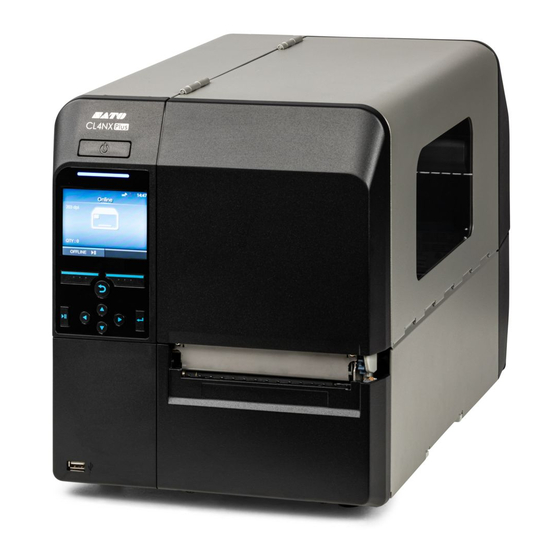
- Page 1 CL4NX-J/CL6NX-J...
-
Page 2: Table Of Contents
Table of Contents Before You Start......................8 About This Manual..........................8 Features of the Product........................9 Safety Precautions........................... 10 Precautions for Installation and Handling..................16 Select a Safe Location........................16 Power Supply..........................17 Printing............................18 Regulatory Approval......................... 19 Environmentally Hazardous Materials....................22 Copyrights/Limitation of Liability/Trademarks...................23 Copyrights............................23 Limitation of Liability........................24 Trademarks.......................... - Page 3 Connecting the Power Cord......................65 Powering On the Product......................67 Powering Off the Product......................68 Initial Setup (Startup Guide)......................70 Overview of the Startup Guide....................71 Startup Screen..........................75 Language Selection........................76 Region Setting with Optional RTC Kit..................77 City Setting with Optional RTC Kit....................78 Date Setting with Optional RTC Kit.................... 79 Time Setting with Optional RTC Kit....................
- Page 4 Loading the Media........................168 Precautions for Loading the Media..................168 Loading the Media Roll......................168 Loading the Fan-fold Media....................172 Loading the Media with the Optional Cutter Unit..............173 Loading the Media with the Optional Dispenser Unit and Liner Discharge Outlet....179 Loading the Media with the Optional Dispenser Unit and Liner Discharge Rewinder..183 Removing the Liner from the Rewinder................188 Loading Ribbon..........................
- Page 5 [AEP].............................436 [System] Menu...........................439 [Regional]..........................440 [Notifications]........................446 [Sound]..........................453 [Energy Saving]........................455 [LCD Brightness]........................456 [Show Total Count].......................456 [Password]..........................457 [Start on AC]........................461 [Tools] Menu..........................462 [Test Print]..........................463 [HEX-Dump]..........................474 [Reset]..........................482 [Profiles]..........................486 [Certificates]..........................489 [Barcode Checker]........................491 [Clone]..........................503 [Support Info]........................504 [Logging Function]........................505 [Startup Guide]........................
- Page 6 Replacing Consumable Parts......................688 Replacing the Print Head......................688 Replacing the Platen Roller...................... 690 Operating the Notification Screen of SOS (SATO Online Services) (SOS users only)....693 Operating the Notification Screen of the SOS (SATO Online Services) On-Demand Mode (SOS users only)..........................693...
- Page 7 Operating the Date and Time Settings Notification Screen of SOS (SATO Online Services) (SOS users only)..........................695 SOS (SATO Online Services) Application (SOS users only)............697 When You Are in Trouble..................698 When an Error Message Appears....................698 Error Message Indication and Operating Procedure When the SOS (SATO Online Services) Is Enabled (SOS users only)......................
-
Page 8: Before You Start
Thank you for purchasing the SATO CL4NX Plus (hereafter referred to as "the product"). This manual supplies basic information on how to operate the CL4NX Plus. Read the manual carefully to understand each function of the CL4NX Plus before operation. -
Page 9: Features Of The Product
Features of the Product CL4NX Plus is a high-performance labeling printer with engineered with a robust die-cast metal and equipped with versatile features for ZERO downtime. The main features of CL4NX Plus are as follows: • High accuracy and high quality printing, with resolutions of 203, 305 and 609 dpi •... -
Page 10: Safety Precautions
Safety Precautions Safety Precautions This topic describes how to use the product safely. Be sure to read the following information carefully before using the product. Pictographic Symbols This operator manual and the product labels use a variety of pictographic symbols. These symbols emphasize the safe and correct use of the product and to prevent injury to others and property damage. - Page 11 • If the product is dropped or breaks, immediately power it off, unplug the power cord from the outlet, and contact your SATO reseller or technical support. Using the product in one of these conditions could result in a fire or electric shock.
- Page 12 Doing so could result in a fire or electric shock. Immediately power off the product, unplug the power cord from the outlet, and contact your SATO reseller or technical support for repairs. Do not use the product...
- Page 13 Do not operate with wet hands • Do not disassemble or modify the product. Doing so could result in a fire or electric shock. Ask your SATO reseller or technical support to conduct internal inspections, adjustments, and repairs. Do not disassemble the product •...
- Page 14 • To replace the print head, follow the procedure in the Operator Manual. If the Operator Manual does not contain this procedure, avoid trying to replace it on your own terms, and contact your SATO reseller or technical support. •...
- Page 15 Print head • When opening and closing the print head, make sure that objects other than media do not get caught. Otherwise, it could result in injury or damage. • When opening and closing the cover, be careful not to get your fingers trapped in between.
-
Page 16: Precautions For Installation And Handling
Select a Safe Location Precautions for Installation and Handling Select a Safe Location Product operations can be affected by the product's environment. Refer to the following instructions regarding how to install and handle the product. • Place the product on a surface that is flat and level. If the surface is not flat and level, this may cause bad print quality. -
Page 17: Power Supply
Power Supply Product operations can be affected by the product's environment. Refer to the following instructions regarding how to install and handle the product. The product requires an AC power supply. • Be sure to connect the product to an AC power supply. •... -
Page 18: Printing
(the combination of media and ribbon), and the product settings (the print speed, the print darkness, etc.). Please sufficiently test the product in your usage environment, and use it with the optimal combination. If anything is unclear, or if you have any questions, contact your SATO sales representative or reseller. -
Page 19: Regulatory Approval
Regulatory Approval FCC Warning You are cautioned that changes or modifications not expressly approved by the party responsible for compliance could void your authority to operate the equipment. This device complies with Part 15 of the FCC Rules. Operation is subject to the following two conditions: (1) this device may not cause harmful interference, and (2) this device must accept any interference received, including interference that may cause undesired operation. - Page 20 Regulatory Approval installed and operated keeping the radiator at least 20 cm or more away from person’s body (excluding extremities: hands, wrists, feet and ankles). Le présent appareil est conforme aux CNR d’Industrie Canada applicables aux appareils radio exempts de licence. L’exploitation est autorisée aux deux conditions suivantes : •...
- Page 21 Disposal of Old Electrical & Electronic Equipment (Applicable in the European Union and other European countries with separate collection systems) A product marked with this symbol on itself or on its packaging shall not be treated as household waste. Instead it shall be handed over to an appropriate collection point for the recycling of electrical and electronic equipment in accordance with local regulations.
-
Page 22: Environmentally Hazardous Materials
Environmentally Hazardous Materials Environmentally Hazardous Materials RoHS Directive This product is in conformity with RoHS Directive 2011/65/EU on the Restriction of the Use of Certain Hazardous Substances in Electrical and Electronic Equipment. Compliance Status of REACH Regulation (1) Status of registered chemical substances No chemical substances are intentionally emitted, nor are there any chemical substances that are registered with the European Chemicals Agency. -
Page 23: Copyrights/Limitation Of Liability/Trademarks
Copyrights/Limitation of Liability/Trademarks Copyrights Any unauthorized reproduction of the contents of this document, in part or whole, is strictly prohibited. © 2019 SATO Corporation. All rights reserved. -
Page 24: Limitation Of Liability
Specifications and contents in this document are subject to change without notice. • Be sure to perform a virus check on the USB memory before connecting it to the product. SATO Corporation cannot be held responsible for any product malfunctions caused by a virus spread... -
Page 25: Trademarks
Trademarks • SATO is a registered trademark of SATO Holdings Corporation and its subsidiaries in Japan, the U.S. and other countries. • NiceLabel is a trademark or registered trademark of Euro Plus d.o.o. in the U.S.A and other countries. •... -
Page 26: Basic Information
Bundled Accessories After unpacking the product, make sure that you have all the bundled accessories. If there are any missing items, contact the SATO reseller where you purchased the product. • User documents (Quick Guide, Safety Instructions, and Global Warranty Program leaflet) •... -
Page 27: Optional Devices
Optional Devices The optional devices for the product are as follows. The optional devices can be factory installed or installed by the customer engineer. Contact your SATO reseller or technical support center. Optional Devices Description Available or Cutter unit Automatically cuts the media in the Available designated number of pages. -
Page 28: Parts Identification
Also, other devices like a barcode checker, barcode scanner or keyboard can be connected. • Be sure to perform a virus check on the USB memory before connecting it to the product. SATO Corporation cannot be held responsible for any product malfunctions caused by a virus spread via USB memory. -
Page 29: Rear View
Also, other devices like a barcode checker, barcode scanner or keyboard can be connected. • Be sure to perform a virus check on the USB memory before connecting it to the product. SATO Corporation cannot be held responsible for any product malfunctions caused by a virus spread via USB memory. (7) LAN connector... -
Page 30: Internal View
Internal View (8) AC input terminal Supplies power to the product through the inserted power cord. Before connecting, make sure that the AC voltage of your region is in the range of AC 100 to 240 V, 50 to 60 Hz. Internal View (1) Ribbon supply spindle (2) Ribbon rewind spindle... -
Page 31: Parts Identification For The Operator Panel
Parts Identification for the Operator Panel Power button To power on the product, press the power button until the LED lights up in blue. To power off the product, press the power button for more than two seconds. (2) LED indicator (3) Color LCD Soft buttons The functions change depending on the screen. - Page 32 Parts Identification for the Operator Panel Example 2: The numerical value input screen of the Settings menu left soft button: Delete one character, right soft button: Save Back button Returns to the previous screen. Line button Toggle between Online/Offline mode or playback/pause the video. Enter button Confirm the selected item or setting value.
-
Page 33: Using The Operator Panel
Using the Operator Panel Display and Operation of the Operator Panel LED Indicator The LED indicator lights up or flashes to show the current status of the product. The product statuses which the LED indicator shows are as follows: LED Indicator Color/Status Description Blue/Lights on... - Page 34 Operations in Online/Offline Mode In Online mode, you can execute the print job. (1) Change to Offline mode. Offline Mode In Offline mode, the print job will stop. You can adjust the print settings, cancel the print job or feed the media. After you complete or cancel the print job, you can show the Settings mode.
-
Page 35: Status Icon
Status Icon The icons on the status bar of the display show the product's status. (1) Status bar Communication Interface Status Icon Description Bluetooth is enabled but not connected. Bluetooth is enabled and connected. Network link is enabled but not connected. Network link is enabled and connected. - Page 36 Status Icon Icon Description NFC is enabled and connected. Not connected to the NTP time server. Wi-Fi is authenticated, but not connected. Wi-Fi is connected. Signal Level: 1 Wi-Fi is connected. Signal Level: 2 Wi-Fi is connected. Signal Level: 3 Wi-Fi is connected.
- Page 37 Product is connected to USB host. Waiting for external input/output signal. Standard code is disabled. The On-Demand mode of the SOS (SATO Online Services) is enabled. The Real Time mode of the SOS is enabled. The product is connected to the SOS cloud.
- Page 38 Status Icon Icon Description Time period set for periodic notification for On-Demand mode for SOS has been reached. Scan the QR code and send the information to the SOS cloud. IP address could not be acquired. Or a communication error has occurred. USB Memory Status Icon Description...
- Page 39 Print Job Status Icon Description Waiting for media removal. Remove the media. Ribbon is near the end. The rest of the ribbon is decreased. Prepare a new ribbon. Label is near the end. The rest of the media is decreased. Prepare new media. Command error detected.
-
Page 40: Operations When Errors Occur
Cancel the error. • Feed the media. • Change to Settings mode. • Change to guidance video. • Change to the SOS error screen on which the QR code and phone number are displayed if the SOS (SATO Online Services) is enabled. - Page 41 • The available operations vary, depending on the situation. (1) Error Icon (2) Error number (3) Clear the error if allowed for the active error. (4) Change to Offline mode if allowed for the active error. (5) The icon appears when the Settings mode or guidance video is available. The SOS icon appears when the SOS is enabled.
- Page 42 Operations When Errors Occur Icon Description Print data is larger than the media size. Sensor error is detected. Print head is unlocked. Print head error is detected. • Communication error is detected. • BCC error is detected. • CRC error is detected. Receive buffer overflow.
- Page 43 Icon Description • Wireless LAN setting error is detected. • Authentication with the server failed. • Authentication with the server timed out. • No print head installed or head resolution was changed. • Product error was detected. The temperature of the print head has exceeded the tolerance range. Bluetooth module is defective.
-
Page 44: Guidance Videos
Guidance Videos Guidance Videos The product contains guidance videos that are shown on the display for visual reference of the product's operations. List of the Guidance Videos The product contains the following guidance videos for visual reference of product operations. The onboard guidance videos are as follows: Guidance Videos Show video from... - Page 45 Guidance Videos Show video from Error screen Startup Guide [Information] Menu Fan-fold media Possible Possible replacement (Cutter) Ribbon replacement Possible Possible Print head replacement Possible Platen roller replacement Possible Cleaning Possible Playing the Guidance Video from the Error Screen Play the guidance video from the error screen and resolve the error by following the procedure of the video.
- Page 46 Guidance Videos 1. Press the button in Online mode. The product changes to Offline mode. 2. Press the button. The product changes to Settings mode. 3. Select [Information] using the buttons.
- Page 47 4. Press the button. The item list appears. 5. Select [Help] using the buttons. 6. Press the button. The guidance video list appears. 7. Select the video for playback using the buttons, and then press the button. The guidance video starts.
-
Page 48: Adjusting The Print Settings During Printing
Adjusting the Print Settings During Printing Operating the Guidance Video (1) Indication panel appears again when one of the buttons is pressed. (2) Stop the playback of the video and return to menu. (3) Playback the video from the start. (4) Playback or pause the video. -
Page 49: Canceling The Print Job
2. Press the button. The Adjustments mode appears. 3. Select an item and adjust the setting. 4. Press the button to return to Offline mode. 5. Press the button to change to Online mode. The print job resumes with the adjusted settings. •... - Page 50 Canceling the Print Job 1. Press the button to change the product to Offline mode. 2. Press the button. A message appears, confirming that you want to cancel the print job. 3. Press the button. The print job is canceled.
-
Page 51: Settings Mode
Settings Mode In the Settings mode, you can set the product's various settings. The topics here explain how to operate the Settings mode. Settings Mode Menus There are six main menus in the Settings mode and each menu contains many layers of submenus. Frequently used settings are also listed in the [Shortcut] menu so that you can directly access them. - Page 52 Changing to the Settings Mode 1. Press the button in Online mode. The product changes to Offline mode. 2. Press the button. The product changes to Settings mode.
-
Page 53: Logging In To/Logging Out Of The Settings Mode
• To exit the Settings mode, press the button. Logging In to/Logging Out of the Settings Mode The Settings mode logs in and logs out by the following procedure, if the password is enabled. • If the password is enabled, input the password after entering the Settings mode. When logged in to the Settings mode, [LOG OUT] appears on the bottom left of the screen. - Page 54 Item Selection 1. Select menu using the buttons. 2. Press the button. The item list appears. 3. Select an item using the buttons. 4. Press the button. If the selected item is a setting item, the setting screen appears. If the selected item is a handling item such as the auto calibration, copy, or delete, the starting screen or confirmation screen appears.
-
Page 55: Setting Value Input Or Selection
(1) There are more items in the next layer. (2) Return to the previous screen. Setting Value Input or Selection This topic describes the character and number input on the setting screen and how to select an item from the list. •... - Page 56 Setting Value Input or Selection • Character Input (1) Text box (2) Selection area (3) Delete the character displayed to the left of the cursor in the text box. (4) Select the character for input using the arrow buttons. The selected character will be highlighted in the selection area.
- Page 57 (2) Selection area (3) Delete the number displayed to the left of the cursor in the text box. (4) Select the number for input using the arrow buttons. The selected number will be highlighted in the selection area. (5) Change the input mode. (6) Save the number you enter in the text box and return to the item list.
- Page 58 Setting Value Input or Selection • Selection from the Box (1) Change the value in the selection box using the buttons. (2) Selection box (3) Perform the function as shown on the screen above. (4) Return to the previous screen. (5) Select an item using the buttons.
- Page 59 (4) Cancel the IP address you enter in the text box and return to the item list. (5) Select the number to input using the buttons.
-
Page 60: Product Memory And Usb Memory
Get the support information • Be sure to perform a virus check on the USB memory before connecting it to the product. SATO Corporation cannot be held responsible for any product malfunctions caused by a virus spread via USB memory. •... -
Page 61: Getting Started
Getting Started Installation Installation Precautions Install the product in a location as follows: • A location that is horizontal and stable. • A location that has sufficient space for operating the product. Do not install the product in a location as follows. Doing so could cause the product to malfunction. •... - Page 62 Installation Precautions • A location with a lot of electrical noise. • A location with a large fluctuation in power. • A location with an explosive atmosphere (flammable gas or vapor).
-
Page 63: Installation Space
Make sure that there is sufficient space around the product so that the top cover can be fully opened when operating or cleaning the product, or replacing consumables. The dimensions of the front view of the product are as follows: CL4NX Plus • The image above is the standard model. -
Page 64: Bottom View
The dimensions of the side view of the product are as follows: • The arrow indicates the front of the product. Bottom View The bottom surface dimensions of the product are as follows: CL4NX Plus • The arrow indicates the front of the product. -
Page 65: Powering On/Off The Product
Make sure that the AC voltage of your region is in the range of AC 100 - 240 V, 50 - 60 Hz. If your local voltage is not in the stated range, contact your SATO reseller or technical support center. - Page 66 Connecting the Power Cord • This product is also designed for IT power distribution system with phase-to-phase voltage 230 V.
-
Page 67: Powering On The Product
Powering On the Product • Do not power on or off the product, connect or disconnect the power cord while your hands are wet. Doing so could cause an electric shock. • You can power on/off the product from the main power source by enabling [Start on AC] under the [System] menu. -
Page 68: Powering Off The Product
Powering Off the Product Powering Off the Product • Do not power on or off the product, connect or disconnect the power cord while your hands are wet. Doing so could cause an electric shock. • Do not power off the product during operation, such as when printing or updating. Doing so could cause a malfunction of the product. - Page 69 2. Press the power button for more than two seconds to power off the product.
-
Page 70: Initial Setup (Startup Guide)
Initial Setup (Startup Guide) Initial Setup (Startup Guide) The topics here explain how to complete the startup guide that appears when you power on the product for the first time after purchase. -
Page 71: Overview Of The Startup Guide
Overview of the Startup Guide When you power on the product for the first time after purchase, the display shows the startup guide. The startup guide is a function to help you through the initial product settings, such as setting date and time, and loading the ribbon and media. - Page 72 Overview of the Startup Guide 4. City Setting with Optional RTC Kit Set the city (time zone). 5. Date Setting with Optional RTC Kit Set the date. 6. Time Setting with Optional RTC Kit Set the time. 7. Print Method Setting Set whether to use the ribbon or direct thermal media to print.
- Page 73 8. Ribbon Setting Load the ribbon. Appears if you have selected [Use Ribbon] in the print method setting. 9. Media Sensor Type Setting Set the sensor type for detecting the media. 10. Media Setting Load the media. 11. Completion of Initial Setup Screen Finish the startup guide.
- Page 74 Overview of the Startup Guide Select whether or not to show the startup guide during the next startup, and press the button to confirm.
-
Page 75: Startup Screen
Startup Screen When you power on the product for the first time after purchase, the display shows the startup guide. 1. Press the power button of the operator panel until the LED lights blue to power on the product. The startup screen appears. -
Page 76: Language Selection
Language Selection Language Selection Select the display language. 1. Select the language name using the buttons. 2. Press the button or button to confirm. -
Page 77: Region Setting With Optional Rtc Kit
Region Setting with Optional RTC Kit Set the region (time zone). 1. Select the region using the buttons. 2. Press the button or button to confirm. -
Page 78: City Setting With Optional Rtc Kit
City Setting with Optional RTC Kit City Setting with Optional RTC Kit Set the city (time zone). 1. Select the city using the buttons. 2. Press the button or button to confirm. -
Page 79: Date Setting With Optional Rtc Kit
Date Setting with Optional RTC Kit Set the date. 1. Select the current value using the buttons, and move the cursor using the buttons. 2. When you have completed the date setting, press the button or button. The confirmation screen appears. 3. -
Page 80: Time Setting With Optional Rtc Kit
Time Setting with Optional RTC Kit Time Setting with Optional RTC Kit Set the time. 1. Select the current value using the buttons, and move the cursor using the buttons. 2. When you have completed the time setting, press the button or button. -
Page 81: Print Method Setting
Print Method Setting Set whether to use the ribbon or direct thermal media to print. 1. Select the print method using the buttons. [Use Ribbon] Print using a ribbon. [Direct Thermal] Print using direct thermal media. 2. Press the button or button to confirm. -
Page 82: Ribbon Setting
Ribbon Setting Ribbon Setting Load the ribbon. You can check the loading method of the ribbon through the video. • Appears if you have selected [Use Ribbon] in the print method setting. 1. Press the button to play the video. The video starts. -
Page 83: Media Sensor Type Setting
Media Sensor Type Setting Set the sensor type for detecting the media. 1. Select the media sensor type using the buttons. [None] Disable the media sensor. [Gap] Select this option when using gap type media. Use the transmissive type sensor. [I-Mark] Select this option when using I-mark type media. -
Page 84: Media Setting
Load the media. You can check the loading method of the media through the video. 1. Press the button. For the models other than the CL4NX Plus linerless model, the selection screen of the video for playback appears. Proceed to step 2. For the CL4NX Plus linerless model, the video appears immediately after the button is pressed. - Page 85 For Dispenser Model [Dispenser] Shows the video on how to eject the liner out of the product. [Rewinder] Shows the video on how to rewind the liner in the product. 3. Press the button or button. The video starts. 4. Load the media while checking the video. 5.
-
Page 86: Completion Of Initial Setup Screen
Completion of Initial Setup Screen Completion of Initial Setup Screen When the startup guide completes, the completion of initial setup screen appears. 1. If you want the startup guide to show the next time you start up, press the button. If not, press the button. -
Page 87: Startup Guide Cancelation
Startup Guide Cancelation You can cancel the startup guide at any time. 1. Press the button while configuring the startup guide. The screen to confirm whether or not to show the startup guide again appears. 2. Select whether or not to show the startup guide during the next startup using the buttons, and press the button to confirm. -
Page 88: Configuring The Product According To Media And Options
Configuring the Product According to Media and Options Configuring the Product According to Media and Options Before starting to print with the product, configure the product according to the media to be used and the installed options. -
Page 89: Print Method
Print Method The product supports two types of print methods, thermal transfer and direct thermal. Thermal transfer Prints using a ribbon. Direct thermal Prints using direct thermal media. • Ribbon is not necessary if you are using direct thermal media. Change the print method according to the following procedure: 1. - Page 90 Print Method 2. Press the button. The product changes to Settings mode. 3. Select [Printing] using the buttons. 4. Press the button. The item list appears.
- Page 91 5. Select [Printing Mode] using the buttons. 6. Press the button. The [Printing Mode] screen appears. 7. Select the print method using the buttons. [Use Ribbon] Prints using a ribbon. [Direct Thermal] Prints using direct thermal media. 8. Press the button to confirm.
-
Page 92: Media Sensor Type
Media Sensor Type Media Sensor Type The product adjusts the print position precisely by detecting I-marks or gaps on the media (label) using media sensors. The I-marks or gaps on each type of media are as follows: I-mark label Gap label I-mark journal paper/ linerless label (1) Media feed direction... - Page 93 2. Press the button. The product changes to Settings mode. 3. Select [Printing] using the buttons. 4. Press the button. The item list appears.
- Page 94 Media Sensor Type 5. Select [Sensor Type] using the buttons. 6. Press the button. The [Sensor Type] screen appears. 7. Select the sensor type to detect the print position using the buttons. [None] Disables the media sensor. [Gap] Select when using gap type media. Use the transmissive type sensor. [I-Mark] Select when using I-mark type media.
- Page 95 8. Press the button to confirm.
-
Page 96: Print Mode
Print Mode Print Mode You can change the print mode of the product according to its usage and installed options. The product has the following print modes: [Continuous] Prints the specified number of media. The media remains in position for printing at all times. [Tear-Off] (Feeding media to the position for manual cutting) After printing the specified number of media, the product feeds the last printed media so that it is fully extended out of the product’s front for removal. - Page 97 1. Press the button in Online mode. The product changes to Offline mode. 2. Press the button. The product changes to Settings mode. 3. Select [Printing] using the buttons.
- Page 98 Print Mode 4. Press the button. The item list appears. 5. Select [Print Mode] using the buttons. 6. Press the button. The [Print Mode] screen appears.
- Page 99 7. Select the print mode using the buttons. • If no option is installed, [Continuous] and [Tear-Off] are available. • If the optional cutter unit is installed, [Continuous], [Tear-Off], [Cutter], and [Cut & Print] are available. • If the optional dispenser unit is installed, [Continuous], [Tear-Off], and [Dispenser] are available.
-
Page 100: Connecting The Product To A Computer
Connecting the Product to a Computer Connecting the Product to a Computer This section explains how to connect the product to a computer, and how to install the printer driver and the All-In-One Tool. -
Page 101: Procedure For Connecting The Product To A Computer
Procedure for Connecting the Product to a Computer The product supports various interfaces and can be connected to a computer in an optimum way for your environment. When you have installed the printer driver to the computer, the data created with the computer (documents and illustrations) can be printed to a label through easy operations. -
Page 102: Connecting Interfaces
Available Interfaces Connecting Interfaces Available Interfaces The product supports the following interfaces. • A product connected with multiple interface cables can continue to operate when receiving data. However, you cannot receive data from more than one interface at a time. Normally, do not use multiple interfaces at a time. •... -
Page 103: Usb Interface Connection (Standard)
• Do not connect or disconnect the interface cables (or use a switch box) while power is supplied to either the product or computer. This may cause damage to the interface circuitry in the product or computer and is not covered by warranty. USB Interface Connection (Standard) Connect the interface cable when the product is powered off. -
Page 104: Bluetooth Interface Connection (Standard)
NFC Interface Connection (Standard) The communication condition settings must be configured according to your network environment. Set the IP address of the product. The IP address of the product can be set through the product's [Interface] menu or the All-In-One Tool. •... -
Page 105: Rs-232C Interface Connection (Standard)
• If it does not communicate well, shift the Android device to the front, back, left and right, and then hold it up again. • For the operation of the NFC for the Android device, refer to the user manual for the Android device. -
Page 106: Ieee1284 Interface Connection (Standard)
IEEE1284 Interface Connection (Standard) • To use the RS-232C interface to connect with the computer, the product's [Tools] > [Barcode Checker] > [Test] > [Interface] menu must be set to [RS-232C]. • The interface settings of the computer can be confirmed by the following. In the Device Manager, right-click [Ports] >... -
Page 107: Wireless Lan Interface Connection (Optional)
• If the product is powered on without installing the printer driver, Windows' Plug & Play runs. When you use the printer driver, do not power on the product while the cable is connected, until instructed in the procedure for installing the printer driver. •... - Page 108 Wireless LAN Interface Connection (Optional) The printer driver performs data communication using the dedicated SOCKET interfaces. The communication condition settings must be configured according to your network environment. Set the IP address of the product. The IP address of the product can be set through the product's [Interface] menu or the All-In-One Tool. •...
-
Page 109: Configuring The Interface Settings
Configuring the Interface Settings Interface Setting Methods Configure the interface settings of the product according to the communication conditions of the connected network and computer. You can set the interface settings of the product doing either of the following. • Set from the [Interface] menu of the product •... - Page 110 Configuring the Interface Settings from the Interface Menu of the Product 2. Press the button. The product changes to Settings mode. 3. Select [Interface] using the buttons. 4. Press the button. The item list appears.
- Page 111 5. Select the interface using the buttons. [Network] Sets the LAN connection and wireless LAN connection. [IEEE1284] Sets the IEEE1284 connection. Appears only if the combo interface board is installed. [RS-232C] Sets the RS-232C connection. Appears only if the combo interface board is installed. [USB] Sets the USB connection.
-
Page 112: Configuring The Interface Settings Using The All-In-One Tool
Installing the All-In-One Tool When you use the All-In-One Tool, you can easily set and manage the product. Download the All-In-One Tool and All-In-One Tool Manual from the SATO All-In-One Tool download site http://www.satoworldwide.com/software/all-in-one-tool.aspx, and install the software to a computer. -
Page 113: Installing The Printer Driver
The printer driver is software that can send data created on the computer (documents and illustrations) to the product and print it to a label. For information about the printer driver, refer to "CL4NX Plus Printer Driver Manual". Installing the Printer Driver (USB) When the computer is connected to the Internet, the printer driver is automatically installed after connecting the USB cable between the computer and the product and powering on the product. - Page 114 Installing the Printer Driver (USB) 7. Click [Next]. 8. Click [Install Printer Driver].
- Page 115 9. Click [USB Port]. 10. Follow the instructions on the screen to power on the product. Windows' Plug & Play runs, and the [Printer Options] screen appears.
- Page 116 Installing the Printer Driver (USB) 11. Click [Install]. 12. When the security warning screen appears, click [Install]. The printer driver is installed. • The warning screen above may not appear, depending on the version of the printer driver or your computer environment. •...
-
Page 117: Installing The Printer Driver (Lan/Wireless Lan)
13. Click [Exit] to complete the installation. 14. In [Devices and Printers], confirm that the product is added to [Printers]. • The settings of the printer driver should be performed by the Administrator Privilege. Installing the Printer Driver (LAN/Wireless LAN) Do the following procedures to install the printer driver using a LAN/Wireless LAN. - Page 118 1. Power on the product, and confirm that the product is connected to the network. 2. Start Windows. 3. Download the printer driver from the SATO printer driver download site. http:// www.satoworldwide.com/software/gallerydriver.aspx 4. Extract the downloaded compressed file of the printer driver.
- Page 119 8. Click [Install Printer Driver]. 9. Click [Network Port]. A list of the printers found on the network appears.
- Page 120 Installing the Printer Driver (LAN/Wireless LAN) 10. Select the printer to add and click [Add]. If the product is not shown on the list, click [Refresh]. If the product is still not shown on the list, add the product using the following procedures. a.
- Page 121 b. Select the model of the product and click [Next]. • Select the model which is compatible with the resolution of the product. The resolution of the product is displayed on the upper left of the Online/Offline screen.
- Page 122 Installing the Printer Driver (LAN/Wireless LAN) c. Select the network port, and click [Next]. If you have selected [Create a new network port], proceed to step d. If you have selected [Use an existing port] and then selected a port from the list, proceed to step 11.
- Page 123 11. Click [Install]. 12. When the security warning screen appears, click [Install]. The printer driver is installed. • The warning screen above may not appear, depending on the version of the printer driver or your computer environment. • If a security warning screen indicating that another process is blocking access appears, follow the steps on the screen, and click [Next].
-
Page 124: Installing The Printer Driver (Bluetooth)
Installing the Printer Driver (Bluetooth) 13. Click [Exit] to complete the installation. 14. Open [Devices and Printers] and confirm that the printer driver is installed. • The settings of the printer driver should be performed by the Administrator Privilege. Installing the Printer Driver (Bluetooth) To use the printer driver with the Bluetooth interface connection, add the product to the computer as a Bluetooth device, and then install the printer driver. - Page 125 The procedure for adding (pairing) the Bluetooth device varies depending on the environment of your computer. The following procedure is an example of Windows 10. For details, refer to the user manual of your computer. • Before starting the installation, close all applications. •...
- Page 126 5. Select the product from the search device list and click [Pair]. • The initial value of the device name for the product is "SATO PRINTER_xxxxxxxxxxxx (BD address)". You can check and change it on the [Bluetooth] > [Name] on the [Interface] menu of the product.
- Page 127 The product is added as a Bluetooth device. 7. Open [Devices and Printers], right-click the product added as a Bluetooth device, and select [Properties].
- Page 128 8. Confirm the port assigned as the [Serial port (SPP)] in the [Services] tab, and click [OK]. Note down this information as it will be necessary for the printer driver installation. 9. Download the printer driver from the SATO printer driver download site. http:// www.satoworldwide.com/software/gallerydriver.aspx 10.
- Page 129 13. Click [Next]. 14. Click [Install Printer Driver].
- Page 130 Installing the Printer Driver (Bluetooth) 15. Click [Other]. 16. Select the model of the product and click [Next].
- Page 131 • Select the model which is compatible with the resolution of the product. The resolution of the product is displayed on the upper left of the Online/Offline screen. 17. Click [Add] and add a port manually. 18. Select [SERIAL (COM)] from the [Select port type] drop down list and click [OK].
- Page 132 Installing the Printer Driver (Bluetooth) 19. Configure the port setting. a. Enter the port name. b. In [Serial port], select the port of the Bluetooth device checked in step 8. c. In [Flow control], select [None]. d. Click [OK]. 20. Click [Next].
- Page 133 21. Click [Install]. 22. When the security warning screen appears, click [Install]. The printer driver is installed. • The warning screen above may not appear, depending on the version of the printer driver or your computer environment. • If a security warning screen indicating that another process is blocking access appears, follow the steps on the screen, and click [Next].
- Page 134 Installing the Printer Driver (Bluetooth) 23. Click [Exit] to complete the installation. 24. Open [Devices and Printers] and confirm that the printer driver is installed. The printer driver can be used with the Bluetooth interface connection. When printing, use the product added when the printer driver was installed, not the product added as the Bluetooth device.
-
Page 135: Installing The Printer Driver (Rs-232C)
1. Connect the product and computer with the RS-232C cable, and power on the product. 2. Start Windows. 3. Download the printer driver from the SATO printer driver download site. http:// www.satoworldwide.com/software/gallerydriver.aspx 4. Extract the downloaded compressed file of the printer driver. - Page 136 Installing the Printer Driver (RS-232C) 7. Click [Next]. 8. Click [Install Printer Driver].
- Page 137 9. Click [Local Port]. 10. Select the model of the product and click [Next].
- Page 138 Installing the Printer Driver (RS-232C) • Select the model which is compatible with the resolution of the product. The resolution of the product is displayed on the upper left of the Online/Offline screen. 11. Select a serial (COM) port and click [Next].
- Page 139 12. Click [Install]. 13. When the security warning screen appears, click [Install]. The printer driver is installed. • The warning screen above may not appear, depending on the version of the printer driver or your computer environment. • If a security warning screen indicating that another process is blocking access appears, follow the steps on the screen, and click [Next].
-
Page 140: Installing The Printer Driver (Ieee1284)
Installing the Printer Driver (IEEE1284) 14. Click [Exit] to complete the installation. 15. Open [Devices and Printers] and confirm that the printer driver is installed. • The settings of the printer driver should be performed by the Administrator Privilege. Installing the Printer Driver (IEEE1284) When the computer is connected to the Internet, the printer driver is automatically installed after connecting the IEEE1284 compliant cable between the computer and the product and powering on the product. - Page 141 [General] tab. 1. Power off the product and connect the IEEE1284 compliant cable to a computer. 2. Start Windows. 3. Download the printer driver from the SATO printer driver download site. http:// www.satoworldwide.com/software/gallerydriver.aspx 4. Extract the downloaded compressed file of the printer driver.
- Page 142 Installing the Printer Driver (IEEE1284) 7. Click [Next]. 8. Click [Install Printer Driver].
- Page 143 9. Click [Local Port]. 10. Select the model of the product and click [Next].
- Page 144 Installing the Printer Driver (IEEE1284) • Select the model which is compatible with the resolution of the product. The resolution of the product is displayed on the upper left of the Online/Offline screen. 11. Select a printer port (LPT) and click [Next].
- Page 145 12. Click [Install]. 13. When the security warning screen appears, click [Install]. The printer driver is installed. • The warning screen above may not appear, depending on the version of the printer driver or your computer environment. • If a security warning screen indicating that another process is blocking access appears, follow the steps on the screen, and click [Next].
- Page 146 Installing the Printer Driver (IEEE1284) 14. Click [Exit] to complete the installation. 15. Power on the product. Windows' Plug & Play runs. 16. Open [Devices and Printers] and confirm that the printer driver is installed. • The settings of the printer driver should be performed by the Administrator Privilege.
-
Page 147: Uninstalling The Printer Driver
When you do the printer driver setup, the properties settings, or the print settings, log in with Administrator Privilege. 1. Power off the product. 2. Start Windows. 3. Download the printer driver from the SATO printer driver download site. http:// www.satoworldwide.com/software/gallerydriver.aspx 4. Extract the downloaded compressed file of the printer driver. - Page 148 Uninstalling the Printer Driver 8. Click [Uninstall Printer Drivers]. 9. Check the check box of the printer you want to uninstall and click [Next]. You can select multiple printers. The printer driver is uninstalled. • When the multiple printers are shown, as long as you do not remove all of the printers, the files related to the installed printer drivers are not removed.
- Page 149 10. Click [Exit].
-
Page 150: Printer Driver Features
Configuring the Printer Driver Settings as an Administrator Printer Driver Features The topics here explain how to open the printer driver setting screens and provide an overview of the printer driver features. Configuring the Printer Driver Settings as an Administrator Configuring the Printer Driver Settings as an Administrator (Windows 7 or Later) When printing a layout created by an application software, configure the printer driver settings first. - Page 151 3. Open the [Sharing] tab.
- Page 152 Configuring the Printer Driver Settings as an Administrator 4. Click [Change Sharing Options].
- Page 153 If [Change Sharing Options] is not shown, do the following procedures. a. Open the [Control Panel] and select [Network and Sharing Center].
- Page 154 Configuring the Printer Driver Settings as an Administrator b. Select [Change advanced sharing settings]. c. In [File and printer sharing], select [Turn off file and printer sharing] and click the [Save changes] button. Configuring the Printer Driver Settings as an Administrator (Windows Server 2008) When printing a layout created by an application software, configure the printer driver settings first.
-
Page 155: Configuring The Driver Settings
The settings of the printer driver should be done by the administrator. If you change a setting value or add a printer port through someone other than the administrator, an error screen appears and the processes you operated are not reflected. In Windows Server 2008, open the properties screen of the printer driver as an administrator with the following procedures. - Page 156 Outputs the current driver settings to a file and reads the settings. (7) [International] Sets the display language of the printer driver. • Be sure to manage the master data for fonts by customer. SATO do not take responsibility for data stored on the product.
-
Page 157: Configuring The Printer Settings
Configuring the Printer Settings [Printing Defaults] and [Printing Preferences] These functions can configure the media settings and printing modes of the product from the printer driver and send them to the product. Use [Printing Defaults] or [Printing Preferences] from the properties screen of the product's printer driver. - Page 158 Configuring the Printer Settings • When you right-click the product in [Devices and Printers] and select [Printing preferences], the same screen as the settings screen for the [Printing Preferences] appears. Overview of the Printer Settings The product settings can be configured from the printer settings screen of [Printing Defaults] or [Printing Preferences].
-
Page 159: Outputting A Label From An Application Software
Selects the unit to be used. (9) [About] Shows the version of the printer driver and provides access to the SATO homepage. Outputting a Label from an Application Software The method for starting a print job varies depending on application software. In general, print jobs begin when you click [Print] button in the dialog that is displayed after selecting [Print] from the [File] menu. - Page 160 Outputting a Label from an Application Software Before starting the print job, confirm that the printer driver to be used in the application software is set to the appropriate printer driver for the product you are using. The method for setting the printer driver varies depending on the application software. In general, select the item you want from the list that is displayed when you select [Print] from the [File] menu, or when you click [▼] in [Printer Name] in the dialog.
-
Page 161: Printer Driver Sharing Function
The following shows how to set the printer driver when using the printer driver with sharing settings. 1. In both the print server and clients, download and install the printer driver from the SATO printer driver download site. http://www.satoworldwide.com/software/ gallerydriver.aspx •... - Page 162 Printer Driver Sharing Function Environment Setting Method Windows Server 2008 In the printer driver, open [Properties] > [Ports], and uncheck [Enable bidirectional support]. Windows 7 or later In the printer driver, open [Printer properties] > [Ports], and uncheck [Enable bidirectional support]. Restrictions When Using the Printer Driver with Sharing Settings When you use the printer driver with sharing settings, the following restrictions occur because bi- directional communication is disabled in the client.
-
Page 163: All-In-One Tool Features
When you add the product to the All-In-One Tool, you can easily set and manage the product. • For details of the All-In-One Tool, download and read the All-In-One Tool Manual from the SATO All-In-One Tool download site. http://www.satoworldwide.com/software/all-in- one-tool.aspx... -
Page 164: Loading Media And Ribbon
Media, Ribbon and Print Methods Loading Media and Ribbon Media, Ribbon and Print Methods The product supports two types of print methods, thermal transfer and direct thermal. The media or ribbon to be used varies depending on the print method. Thermal transfer Prints using a ribbon. -
Page 165: Loading Media
Loading Media The topics here explain how to load the media. -
Page 166: Usable Media
Usable Media Usable Media The product can print on the following two types of media. • Media roll • Fan-fold media The product uses media sensors to detect I-marks or gaps on the media in order to precisely print the content. -
Page 167: Adjusting The Position Of The Media Sensor
Adjusting the Position of the Media Sensor When you use nonstandard media (for example, media with printing on the underside, or media with a special shape), the media sensor cannot detect the I-mark or gap of the media correctly. In such a case, adjust the position of the media sensor to detect the I-mark or gap correctly. -
Page 168: Loading The Media
Loading the Media Roll Loading the Media Precautions for Loading the Media Use genuine SATO media and ribbons for the product, for optimum print quality. • The print head and its surroundings are hot after printing. Be careful not to touch it, to avoid being burned. - Page 169 • Open the top cover fully to prevent accidental drop of the cover. 2. Push the head lock lever (2) towards the rear.
- Page 170 Loading the Media Roll 3. Pull the media holder guide (3) and media guide (4) away from the product. Turn the knob (5) counterclockwise to release the media guide. 4. Load the media in the media holder (6). Make sure that the media roll is all the way in towards the inside of the product. 5.
- Page 171 6. Pass the media below the media damper (7) and the media sensor guide (8) while pushing the media to inside of the product. Make sure that the end of the media extends out the front of the product. 7. Press the print head down until the head lock lever is locked. 8.
-
Page 172: Loading The Fan-Fold Media
Loading the Fan-fold Media • When closing the top cover, be careful not to pinch your fingers. 10. Perform a test print to make sure that the media is loaded correctly. • You need to load the ribbon when printing using thermal transfer. Loading the Fan-fold Media 1. -
Page 173: Loading The Media With The Optional Cutter Unit
3. Place the fan-fold media on a flat location, and load the media from the media slot on the rear or the bottom of the product. The routing path of the media is shown in the below picture. Load the media from the rear of the product Load the media from the bottom of the product. - Page 174 Loading the Media with the Optional Cutter Unit • Open the top cover fully to prevent accidental drop of the cover. 2. Push the head lock lever (2) towards the rear.
- Page 175 3. Pull the media holder guide (3) and media guide (4) away from the product. Turn the knob (5) counterclockwise to release the media guide. 4. Load the media roll or the fan-fold media. For Media Roll The routing path of the media is shown in the below picture. Face-in media Face-out media...
- Page 176 Loading the Media with the Optional Cutter Unit a. Load the media in the media holder (6). Make sure that the media roll is all the way in towards the inside of the product. b. Push the media holder guide (3) lightly against the media roll. For Fan-fold Media a.
- Page 177 Load the media from the rear of the product Load the media from the bottom of the product. • When loading the media, make sure that the print side faces up. 5. Pull the tab (7) of the cutter unit in the direction A, and then open up the cutter- open lever to (B).
- Page 178 Loading the Media with the Optional Cutter Unit 7. Press the print head down until the head lock lever is locked. 8. Close the cutter and then push the tab (7) in the reverse direction to lock it. 9. Press the media guide (4) lightly against the end of the media, and then turn the knob (5) to lock the media guide.
-
Page 179: Loading The Media With The Optional Dispenser Unit And Liner Discharge Outlet
• You need to load the ribbon when printing using thermal transfer. Loading the Media with the Optional Dispenser Unit and Liner Discharge Outlet The below topic describes the procedure to dispense the label and eject the liner out of the product. 1. - Page 180 Loading the Media with the Optional Dispenser Unit and Liner Discharge Outlet 3. Pull the media holder guide (3) and media guide (4) away from the product. Turn the knob (5) counterclockwise to release the media guide. 4. Load the media in the media holder (6). Make sure that the media roll is all the way in to inside of the product.
- Page 181 6. Pass the media below the media damper (7) and the media sensor guide (8) while pushing the media to inside of the product. Make sure that the end of the media extends out the front of the product. 7. Press the tab (9) at the front of the product to open the dispenser unit (10). 8.
- Page 182 Loading the Media with the Optional Dispenser Unit and Liner Discharge Outlet 9. Pass the liner (12) through the gap of the dispenser unit to the outside of the product. 10. Adjust the dispenser roller (13) to the center of the label. 11.
-
Page 183: Loading The Media With The Optional Dispenser Unit And Liner Discharge Rewinder
Loading the Media with the Optional Dispenser Unit and Liner Discharge Rewinder The below topic describes the procedure to dispense the label and rewind the liner in the product. • The maximum diameter of the liner that can be rewound in the product is φ120 mm (4.72"). - Page 184 Loading the Media with the Optional Dispenser Unit and Liner Discharge Rewinder • Open the top cover fully to prevent accidental drop of the cover. 2. Push the head lock lever (2) towards the rear.
- Page 185 3. Pull the media holder guide (3) and media guide (4) away from the product. Turn the knob (5) counterclockwise to release the media guide. 4. Load the media in the media holder (6). Make sure that the media roll is all the way in to inside of the product. 5.
- Page 186 Loading the Media with the Optional Dispenser Unit and Liner Discharge Rewinder 6. Pass the media below the media damper (7) and the media sensor guide (8) while pushing the media to inside of the product. Make sure that the end of the media extends out the front of the product. 7.
- Page 187 9. Pass the liner (12) through the gap of the dispenser unit to the inside of the product. 10. Adjust the dispenser roller (13) to the center of the label. 11. Pass the liner (12) below the liner rewinder (14), and attach it with the clip (15). 12.
-
Page 188: Removing The Liner From The Rewinder
Removing the Liner from the Rewinder 13. Close the print head. 14. Close the dispenser unit. 15. Press the media guide lightly against the end of the media, and then turn the knob to lock the media guide. 16. Close the top cover. •... -
Page 189: Loading Ribbon
Loading Ribbon You need to load the ribbon when printing using thermal transfer. The topics here explain how to load and replace the ribbon. -
Page 190: Checking The Ink Side Of The Ribbon
Checking the Ink Side of the Ribbon Checking the Ink Side of the Ribbon There are two wind directions for the ribbon. Face-out means the ink is on the outer side and Face-in means the ink is on the inner side. The product supports both wind directions. You can examine the ink side of the ribbon using the following procedure. -
Page 191: Loading The Ribbon
Touching the edge of the print head with your bare hand could cause injury. • Use genuine SATO media and ribbons for the product, for optimum print quality. • The routing path of the ribbon is shown in the below picture. - Page 192 Loading the Ribbon • Open the top cover fully to prevent accidental drop of the cover. 2. Push the ribbon rewind spindle (2) all the way in. If there is any ribbon on the ribbon rewind spindle, remove it from the spindle before installing new ribbon.
- Page 193 4. Load the ribbon (4) onto the ribbon supply spindle (5). While taking note of the wind direction, insert the ribbon all the way in. 5. From the ribbon supply spindle (5), pass the ribbon below the print head (6). 6.
- Page 194 Loading the Ribbon 7. If the media is already loaded, press the print head down until the head lock lever is locked. If the media is not loaded, load the media. 8. Close the top cover. • When closing the top cover, be careful not to pinch your fingers.
-
Page 195: Replacing The Ribbon
Replacing the Ribbon 1. Open the top cover (1). • Open the top cover fully to prevent accidental drop of the cover. 2. Push the head lock lever (2) towards the rear. - Page 196 Replacing the Ribbon 3. Press the tab (3) on the tip of the ribbon rewind spindle to pull it out. 4. Pull to remove the used ribbon from the ribbon rewind spindle. 5. Push the ribbon rewind spindle (4) all the way in. 6.
- Page 197 7. Load the ribbon (5) onto the ribbon supply spindle (6). While taking note of the wind direction, insert the ribbon all the way in. 8. From the ribbon supply spindle (6), pass the ribbon below the print head (7). 9.
- Page 198 Replacing the Ribbon 10. Press the print head down until the head lock lever is locked. 11. Close the top cover. • When closing the top cover, be careful not to pinch your fingers. 12. Press the button (FEED) to feed the media. 13.
-
Page 199: When To Replace Media And Ribbon
When to Replace Media and Ribbon Checking the Remaining Amount of Media and Ribbon You can check the remaining amount of media and ribbon according to the following procedure. • Checking through the window on the right side of the product You can visually check the remaining amount of media and ribbon in the product through the window on the right side of the product (1). -
Page 200: Conditions That Trigger Paper End, Label Near End, Ribbon End And Ribbon Near End
Conditions That Trigger Paper End Conditions That Trigger Paper End, Label Near End, Ribbon End and Ribbon Near End Conditions That Trigger Paper End The conditions that trigger paper end vary depending on the operation of the product. Conditions That Trigger Paper End in the Feeding Operation A paper-end occurs if the no-paper condition persists even after the paper-end sensor detects the no- paper condition when 15 mm (0.59") continues to be fed. - Page 201 2. If the amount of printing remaining is less than the distance between the print head position and paper end sensor -15 mm (-0.59"), a paper end error occurs after completing the output of 1. If the amount of media remaining is more than the distance between the print head position and paper end sensor -15 mm (-0.59"), a paper end error occurs right after detecting the paper end, and the product will reprint after clearing the paper end error.
- Page 202 Conditions That Trigger Paper End • When the Amount of Printing Remaining Is More Than the Amount of Media Remaining If the amount of printing remaining is more than the amount of media remaining when a paper end error is detected, the product cannot finish the print job. Printing stops immediately and a paper end error occurs.
-
Page 203: Conditions That Trigger Label Near End
If there are multiple sheets between the print head and paper end sensor when a paper end error is detected, a paper end error will occur only after finishing the label currently being printed. (1) Print head position (2) Paper end sensor (3) Amount of media remaining (4) Amount of printing remaining Conditions That Trigger Label Near End... -
Page 204: Various Settings Of The Product
[Shortcut] Menu Various Settings of the Product The Product's [Settings] Menu [Shortcut] Menu Frequently used settings are listed in the [Shortcut] menu. -
Page 205: [Printing] Menu
[Printing] Menu The following settings are available in the [Printing] menu: Label Length Set the length of the media. Label Width Set the width of the media. Auto Measure Automatically measure the length of the media. Printing Mode Set whether to print using a ribbon or direct thermal media. Ribbon Near End Enable or disable the warning when the ribbon is about to run out. -
Page 206: [Label Length]
Set the length of the media. The setting range varies depending on the print resolution of the product. The setting range of the label length is as follows: Resolution CL4NX Plus 203 dpi 1 to 20000 dots (1 dot = 0.125 mm (0.0049")) -
Page 207: [Label Width]
Resolution CL4NX Plus (1 dot = 0.042 mm (0.0017")) • Set the label size to a value that includes the liner. [Label Width] Set the width of the media. The setting range varies depending on the print resolution of the product. -
Page 208: [Auto Measure]
[Auto Measure] [Auto Measure] The product automatically measures the length of the media. The measured length of the media will be automatically saved in [Label Length]. The Auto Measure function can be performed when [Sensor Type] is set to [Gap] or [I-Mark]. The setting procedure of the label length using the Auto Measure function is as follows: 1. -
Page 209: [Printing Mode]
[Printing Mode] Set whether to print using a ribbon or direct thermal media. The options are as follows: Use Ribbon Print using a ribbon. Direct Thermal Print using direct thermal media. [Ribbon Near End] Shows or does not show the warning icon when the ribbon is about to run out. Printing does not stop even if the warning icon shows up. -
Page 210: [Speed]
609 dpi (24 dots/mm) 2 to 6 ips (inches/sec) (50.8 to 152 mm/sec) • If the optional linerless cutter kit is installed to CL4NX Plus, the setting range is as follows: ◦ The setting range is 2 to 6 ips (inches/sec) (50.8 to 152 mm/sec) regardless of the printing resolution. -
Page 211: [Sensor Type]
[Sensor Type] Set the sensor type for detecting the media. The options are as follows: None Disable the media sensor. Select when using gap type media. Use the transmissive type sensor. I-Mark Select when using I-mark type media. Use the reflective type sensor. •... - Page 212 [Micro Label Print Mode] Set the micro label print mode operation. Micro Label Print Mode is a mode to provide high accuracy printing for small sized labels. • The improved accuracy provided by micro label print mode is for labels sizes of less than 53 mm (incl.
- Page 213 Enable or disable the use of Micro Label Print Mode. The options are as follows: Enabled Enable Micro Label Print Mode. Disabled Disable Micro Label Print Mode. [Auto Label Length Detection] Enable or disable automatic measurement of label length when the [Micro Label Print Mode] is set to [Enabled].
- Page 214 Label Length Detection] is set to [Disabled]. The setting range varies depending on the print resolution of the product. The setting range of the label length is as follows: Resolution CL4NX Plus 203 dpi 72 to 424 dots (1 dot = 0.125 mm (0.0049"))
-
Page 215: [Auto-Mode]
Resolution CL4NX Plus (1 dot = 0.042 mm (0.0017")) • Set the label size to a value that includes the liner. [Auto-mode] When using [Auto-mode], the print mode changes automatically according to the status of the installed option unit. The options are as follows: Enabled The print mode changes automatically. -
Page 216: [Print Mode]
[Print Mode] [Print Mode] Set the print mode. The options are as follows: Continuous Continuously print the specified number of the media. The media remains in position for printing at all times. Tear-Off (Feeding media to the position for manual cutting) After continuously printing the specified number of the media, feed the media to the point to remove the media. -
Page 217: [Backfeed]
• If no option is installed, [Continuous] and [Tear-Off] are available. • If the optional cutter unit is installed, [Continuous], [Tear-Off], [Cutter], and [Cut & Print] are available. • If the optional dispenser unit is installed, [Continuous], [Tear-Off], and [Dispenser] are available. -
Page 218: [Eject Cut]
[Darkness Range] [Eject Cut] Set the Eject cut motion for the last printed media. Cut the last media after the specified timing. Appears if you have selected [Cut & Print] in the [Print Mode] menu. The setting range is Off, or from 1 to 5 (sec). [Darkness Range] Set the range of the print darkness. -
Page 219: [Darkness]
[Darkness] Specify the print darkness from 10 steps. The setting range is from 1 to 10. 1 is the lightest and 10 is the darkest. • To further fine tune the print darkness, set [Printing] > [Advanced] > [Adjustments] > [Darkness Adjust]. - Page 220 [Imaging] Adjusting direction of the print reference position and base reference point (1) Feed direction (2) Liner (3) Label (4) Gap between labels (5) Adjustment of vertical base reference point (6) Base reference point after adjustment (7) Adjustment of horizontal base reference point (8) Print reference position [Vertical] Set the print position in the vertical direction.
- Page 221 (1) Feed direction The setting range varies depending on the print resolution of the product. The setting range is as follows: Resolution CL4NX Plus 203 dpi -19999 to 0 to 19999 dots (1 dot = 0.125 mm (0.0049")) 305 dpi -17999 to 0 to 17999 dots (1 dot = 0.083 mm (0.0033"))
-
Page 222: [Advanced]
(1) Feed direction The setting range varies depending on the print resolution of the product. The setting range is as follows: Resolution CL4NX Plus 203 dpi -831 to 0 to 831 dots (1 dot = 0.125 mm (0.0049")) 305 dpi -1247 to 0 to 1247 dots (1 dot = 0.083 mm (0.0033")) - Page 223 The setting items are as follows: Calibrate Adjust the media sensor. Head Check Check if there is a broken element of the print head. Head Check Mode Set the mode for head check. ◦ Appears if you have selected [All] or [Barcode] in the [Head Check] menu. Every Page Set the interval for head check.
- Page 224 [Advanced] Label Near End Enable or disable the warning when the media is about to run out. [Calibrate] Adjust the media sensor level. In instances of media detection malfunction, adjust the media sensor level (Gap and I-mark sensors). The setting items are as follows: Auto-calibration Automatically adjust the sensor level.
- Page 225 7. The result of the sensor adjustment is shown. To exit the adjustment, press the button. 8. Set to Offline mode. Press the button to confirm that the media is fed correctly. • If the media is not fed correctly after doing [Auto-calibration], contact your SATO reseller or technical support center.
- Page 226 [Advanced] [GAP Levels] Manually set the Gap sensor level. The setting procedure is as follows: First, adjust the "Low" level (voltage) of the Gap sensor. 1. Remove the label from the liner. 2. Pass the liner through the media sensor. Align it so that the media sensor does not detect the I- mark (black mark).
- Page 227 ◦ Low (with only liner) ≤ 0.5 (V) ◦ High (media attached with liner) - Low ≥ 1.0 (V) [GAP Slice Level] Set the Gap sensor slice level. The setting procedure is as follows: 1. Use the following formula to calculate the slice level: (High level - Low level) x 0.3 + Low level = slice level 2.
- Page 228 [Advanced] [I-Mark Levels] Manually set the I-mark sensor level. The setting procedure is as follows: First, adjust the "Low" level (voltage) of the I-mark sensor. 1. Pass the media (attached with liner) between the media sensors. Align it so that the media sensor does not detect the I-mark (black mark).
- Page 229 [I-Mark Slice Level] Set the I-mark sensor slice level. The setting procedure is as follows: 1. Use the following formula to calculate the slice level: (High level - Low level) x 0.7 + Low level = slice level 2. Select the [I-Mark Slice Level] in the [Calibrate] menu and press the button.
- Page 230 [Advanced] The options are as follows: Disable the Head Check. Check the entire print area. Barcode Check only the area for printing a barcode. Head check is not applicable for barcodes printed as graphic data. • Head check is a reference for checking for a broken element of the print head. This function does not guarantee barcode readability.
- Page 231 [Every Page] Perform the head check for each specified number of media. Appears if you have selected [Every Page] in the [Head Check Mode] menu. The setting range is from 1 to 999999. [Check Media Size] Enable or disable media size check. Appears if you have selected [Gap] or [I-Mark] in the [Sensor Type] menu.
- Page 232 [Advanced] Disabled Disable media size check. [Adjustments] Correct the offset position, print position and print darkness. The setting items are as follows: Offset Adjusts the backfeed/stop position for Tear-off/Cut/Dispense operation. Pitch Adjusts the print start position thus effects the vertical print position placement. Pitch Offset Adjusts the offset position and the pitch position at the same time.
- Page 233 The setting range varies depending on the print resolution of the product. The setting range is as follows: Resolution CL4NX Plus 203 dpi -30 to 0 to 30 dots (1 dot = 0.125 mm (0.0049"))
- Page 234 (1) Feed direction The setting range varies depending on the print resolution of the product. The setting range is as follows: Resolution CL4NX Plus 203 dpi -30 to 0 to 30 dots (1 dot = 0.125 mm (0.0049")) 305 dpi -45 to 0 to 45 dots (1 dot = 0.083 mm (0.0033"))
- Page 235 (3) Pitch position (leading edge of media position that decides the vertical print position) The setting range varies depending on the print resolution of the product. The setting range is as follows: Resolution CL4NX Plus 203 dpi -392 to 0 to 392 dots (1 dot = 0.125 mm (0.0049"))
- Page 236 [Advanced] Fine tune the print darkness. The setting range is from 0 to 99. 0 is the lightest and 99 is the darkest. [Start Online] Select default mode when the product is powered on. The options are as follows: Enabled The product powers on in Online mode.
- Page 237 Enabled Feed the media when changing to Online mode after recovering from an error. Disabled Do not feed the media when changing to Online mode after recovering from an error. However, if [Feed At Power On] is set to [Enabled], the product feeds the media when it is powered on and changes to Online mode.
- Page 238 The actual media feed amount is the value of [Offset] + [Finisher Feed]. The setting range varies depending on the print resolution of the product. The setting range is as follows: Resolution CL4NX Plus 203 dpi 0 to 2040 dots (1 dot = 0.125 mm (0.0049"))
- Page 239 [Head Base Position] Set the position used for the base reference point for printing. The options are as follows: Item CL4NX Plus [Standard] Print with a standard base reference point. [Left-justify] Move the base reference point 2 mm (0.08") to the left...
- Page 240 [Advanced] • A message prompting you to restart the product will appear on the Online/Offline screen if you have made any changes. In such a case, reboot the product to apply the settings. [Prioritize] For product settings, set whether to prioritize the settings that are done through the product or through commands.
- Page 241 The setting range varies depending on the print resolution of the product. The setting range is as follows: Resolution CL4NX Plus 203 dpi 0 to 20000 dots (1 dot = 0.125 mm (0.0049"))
- Page 242 [Advanced] [Label Near End] Shows or does not show the warning icon when the media is about to run out. Printing does not stop even if the warning icon shows up. The options are as follows: Enabled Shows the warning icon. Disabled Does not show the warning icon.
-
Page 243: [Interface] Menu
[Interface] Menu The following settings are available in the [Interface] menu: Network Set the LAN connection and wireless LAN connection. IEEE1284 Set the IEEE1284 connection. ◦ Appears only if the combo interface board is installed. RS-232C Set the RS-232C connection. ◦... -
Page 244: [Network]
The setting items are as follows: Settings Set LAN or wireless LAN, or select an interface. Services Set the TCP/IP port number, NTP, LPD, FTP, SNMP, or SOS (SATO Online Services). Advanced Set the advanced function for the interface. [Settings] Set the LAN or wireless LAN, or select the interface. - Page 245 Set the LAN. Wi-Fi Set the wireless LAN. ◦ Appears only if you have installed the optional wireless LAN. Interface Select the network interface. ◦ This item is to select the network interface from LAN or wireless LAN when you have installed the optional wireless LAN.
- Page 246 [Network] [IPv4] Set IPv4 for the LAN. The setting items are as follows: Mode Select the IP address assignment method. DHCP / Renew Lease Update the lease time and get the IP address from the DHCP server again. ◦ Appears only if you have selected [DHCP] in the [Mode] menu and LAN is the active interface. ◦...
- Page 247 Set and check DNS server addresses. If you have selected [Static] in the [Mode] menu, select this to set and check DNS server addresses. • After doing the settings, press the button to enable the new settings. Press button to cancel the new settings and return to the previous settings. •...
- Page 248 [Network] [IP Address] If you have selected [Static] in the [Mode] menu, set the IP address. The setting range is as follows: 000.000.000.000 to 255.255.255.255 [Netmask] If you have selected [Static] in the [Mode] menu, set the subnet mask address. Each group of the address can be set cyclically among 0, 128, 192, 224, 240, 248, 252, 254 and 255.
- Page 249 [Gateway] If you have selected [Static] in the [Mode] menu, set the default gateway address. The setting range is as follows: 000.000.000.000 to 255.255.255.255 [DNS] If you have selected [Static] in the [Mode] menu, set and check DNS server addresses. The setting range is as follows: 000.000.000.000 to 255.255.255.255 •...
- Page 250 [Network] [IPv6] Set the IPv6 for the LAN. The setting items are as follows: Mode Select the IP address assignment method or disable IPv6. DHCP / Renew Lease Update the lease time and get the IP address from the DHCP server again. ◦...
- Page 251 • After doing the settings, press the button to enable the new settings. Press button to cancel the new settings and return to the previous settings. • You cannot change [IP Address], [Prefix Length], [Gateway], or [DNS] if [Mode] is anything other than [Static].
- Page 252 [Network] [IP Address] If you have selected [Static] in the [Mode] menu, set the IP address. The setting range is as follows: 0:0:0:0:0:0:0:1 to ffff:ffff:ffff:ffff:ffff:ffff:ffff:ffff [Prefix Length] If you have selected [Static] in the [Mode] menu, set the prefix. The setting range is from 1 to 128.
- Page 253 [Gateway] If you have selected [Static] in the [Mode] menu, set the default gateway address. The setting range is as follows: 0:0:0:0:0:0:0:0 to ffff:ffff:ffff:ffff:ffff:ffff:ffff:ffff [DNS] If you have selected [Static] in the [Mode] menu, set the primary address of the DNS server. The setting range is as follows: 0:0:0:0:0:0:0:0 to ffff:ffff:ffff:ffff:ffff:ffff:ffff:ffff •...
- Page 254 [Network] [Proxy] Set the proxy for the LAN. The setting items are as follows: Enabled Enable or disable use of proxy. Server Set the proxy server address. Exclude Exclude the proxy from usage. [Enabled] Enable or disable use of proxy. The options are as follows: Enabled Enable proxy server usage.
- Page 255 Disabled Disable proxy server usage. • To enable the proxy, [Server] should be set and [Exclude] must contain at least 127.0.0.1 and localhost. [Server] Set the name or IP address of the proxy server. Example of input) 172.128.1.100:8080 • Server should be set with a valid name or IP address and port number. •...
- Page 256 [Network] [Wi-Fi] Set the wireless LAN. Appears only if you have installed the optional wireless LAN. The setting items are as follows: IPv4 Configure IPv4 for Wi-Fi. IPv6 Configure IPv6 for Wi-Fi. Proxy Configure the proxy for Wi-Fi. Wi-Fi Protected Setup Set the wireless LAN connection with the Wi-Fi Protected Setup (WPS) function.
- Page 257 WEP Conf. Set the WEP key. ◦ Appears only if you have selected [WEP] in the [Security] menu. WPA Conf. Set the WPA authentication. ◦ Appears only if you have selected [WPA2/WPA] or [WPA2] in the [Security] menu. EAP Conf. Set the EAP authentication.
- Page 258 [Network] IP Address Set and check the IP address. If you have selected [DHCP] in the [Mode] menu, the screen shows the IP address you received from the DHCP server. If you have selected [Static] in the [Mode] menu, select to set the IP address. Netmask Set and check the subnet mask address.
- Page 259 DHCP Automatically retrieve the IP address, gateway and subnet mask from the DHCP server. Static Manually set the IP address, gateway and subnet mask. [IP Address] If you have selected [Static] in the [Mode] menu, set the IP address. The setting range is as follows: 000.000.000.000 to 255.255.255.255 [Netmask] If you have selected [Static] in the [Mode] menu, set the subnet mask address.
- Page 260 [Network] [Gateway] If you have selected [Static] in the [Mode] menu, set the default gateway address. The setting range is as follows: 000.000.000.000 to 255.255.255.255 [DNS] If you have selected [Static] in the [Mode] menu, set and check DNS server addresses. The setting range is as follows: 000.000.000.000 to 255.255.255.255 •...
- Page 261 [IPv6] Configure IPv6 for Wi-Fi. The setting items are as follows: Mode Select the IP address assignment method or disable IPv6. DHCP / Renew Lease Update the lease time and get the IP address from the DHCP server again. ◦ Appears only if you have selected [DHCP] in the [Mode] menu.
- Page 262 [Network] • After doing the settings, return to the [Wi-Fi] screen by pressing the button, and then press the button to enable the new settings. Press the button to cancel the new settings and return to the previous settings. • When [Wi-Fi Direct] is active, this [IPv6] screen does not appear.
- Page 263 [IP Address] If you have selected [Static] in the [Mode] menu, set the IP address. The setting range is as follows: 0:0:0:0:0:0:0:1 to ffff:ffff:ffff:ffff:ffff:ffff:ffff:ffff [Prefix Length] If you have selected [Static] in the [Mode] menu, set the prefix. The setting range is from 1 to 128.
- Page 264 [Network] [Gateway] If you have selected [Static] in the [Mode] menu, set the default gateway address. The setting range is as follows: 0:0:0:0:0:0:0:0 to ffff:ffff:ffff:ffff:ffff:ffff:ffff:ffff [DNS] If you have selected [Static] in the [Mode] menu, set the primary address of the DNS server. The setting range is as follows: 0:0:0:0:0:0:0:0 to ffff:ffff:ffff:ffff:ffff:ffff:ffff:ffff •...
- Page 265 [Proxy] Configure the proxy for Wi-Fi. The setting items are as follows: Enabled Enable or disable use of proxy. Server Set the proxy server address. Exclude Exclude the proxy from usage. [Enabled] Enable or disable use of proxy. The options are as follows: Enabled Enable proxy server usage.
- Page 266 [Network] Disabled Disable proxy server usage. • To enable the proxy, [Server] should be set and [Exclude] must contain at least 127.0.0.1 and localhost. [Server] Set the name or IP address of the proxy server. Example of input) 172.128.1.100:8080 • Server should be set with a valid name or IP address and port number.
- Page 267 [Wi-Fi Protected Setup] Set the wireless LAN connection using the push button or PIN code method. The setting items are as follows: Button (PBC) Set the wireless LAN connection using the push button method. Set the wireless LAN connection using the PIN code method. •...
- Page 268 [Network] 3. When the connection to the access point is established, [Successfully configured.] appears on the screen. [PIN] Set the wireless LAN connection using the PIN code method. 1. Select [PIN] in the [Wi-Fi Protected Setup] menu and press the button.
- Page 269 3. When the connection to the access point is established, [Successfully configured.] appears on the screen. [Wi-Fi Direct] Connect without group Connect with group Set the Wi-Fi Direct function.
- Page 270 [Network] The Wi-Fi Direct function is enabled if you have selected [Infrastructure] in the [Mode] menu. If you have changed the setting from [Ad-hoc] to [Infrastructure] in the [Mode] menu, reboot the product before setting the Wi-Fi Direct function. The setting procedure is as follows: 1.
- Page 271 • You can connect a maximum of 10 devices. • When Wi-Fi Direct is active, [Device Name] cannot be changed. • [Start Group] and [Remove Group] are shown only if Wi-Fi is active and the product is not connected to a Wi-Fi Direct network. •...
- Page 272 [Network] [Hidden SSID] Set the hidden SSID (stealth function). Appears if you have selected [Infrastructure] in the [Mode] menu. The options are as follows: Enabled Enable the hidden SSID. Disabled Disable the hidden SSID. [Mode] Set the communication method of the wireless LAN. The options are as follows: •...
- Page 273 [Channel] Set the communication channel. [Channel] can be set only if you have selected [Ad-hoc] in the [Mode] menu. The number of channels you can set varies depending on the region of the product. [Security] Set the security method of the network. Set the security methods so that the product, host and network devices match.
- Page 274 [Network] [WEP Conf.] Set the WEP key. Appears if you have selected [WEP] in the [Security] menu. The setting items are as follows: Authentication Set the WEP authentication method. Key Index Set the key index. Key #1 to Key #4 Set the WEP key1 - key4.
- Page 275 [Key Index] Set the key index. Set the key index (WEP key) according to the access point of the wireless LAN you connect. The setting range is from 1 to 4. • Depending on the connecting device, the range of the key index may be 0 to 3. In such a case, if you have set the product to 1, set the connecting device to 0.
- Page 276 [Network] [WPA Conf.] Set the WPA authentication. Appears only if you have selected [WPA2/WPA] or [WPA2] in the [Security] menu. The setting items are as follows: WPA Authentication Set the WPA authentication method. Set the PSK shared key. ◦ Appears only if you have selected [Personal (PSK)] in the [WPA Authentication] menu. EAP Conf.
- Page 277 Set the WPA authentication method. The options are as follows: • [Personal (PSK)] • [Enterprise (802.1x)] • [CCKM] [PSK] Set the PSK shared key. Appears only if you have selected [Personal (PSK)] in the [WPA Authentication] menu. You can enter 8 to 63 ASCll characters or 64 hexadecimal digits. Alphabets, numbers and symbols can be used.
- Page 278 [Network] Inner Method Set the inner method. ◦ Appears only if you have selected [FAST], [PEAP], or [TTLS] in the [EAP Mode] menu. Username Set the user name. Password Set the password. Anon. Outer ID Set the external ID. ◦ Appears only if you have selected [FAST], [PEAP], or [TTLS] in the [EAP Mode] menu.
- Page 279 [EAP Mode] Set the EAP Mode (authentication mode). The options are as follows: • [FAST] • [LEAP] • [PEAP] • [TLS] • [TTLS] [Inner Method] Set the inner method. Appears only if you have selected [FAST], [PEAP], or [TTLS] in the [EAP Mode] menu. •...
- Page 280 [Network] [Username] Set the user name. You can enter 0 to 63 characters. Alphabets, numbers and symbols can be used. [Password] Set the password. You can enter 0 to 32 characters. Alphabets, numbers and symbols can be used.
- Page 281 [Anon. Outer ID] Set the external ID. Appears if you have selected [FAST], [PEAP], or [TTLS] in the [EAP Mode] menu. You can enter 0 to 63 characters. Alphabets, numbers and symbols can be used. [Verify Server Cert.] Enable or disable server certificate validation. Appears if you have selected anything other than [LEAP] in the [EAP Mode] menu.
- Page 282 [Network] [Private Key P/W] Set the Private Key password. Appears only if you have selected [TLS] in either the [EAP Mode] menu or [Inner Method] menu. You can enter 0 to 64 characters. Alphabets, numbers and symbols can be used. [PAC Auto Provisioning] Enable or disable PAC auto provisioning.
- Page 283 [PAC P/W] Set the PAC password. Appears only if you have selected [FAST] in the [EAP Mode] menu and if you have selected [Disabled] in [PAC Auto Provisioning]. You can enter 0 to 64 characters. Alphabets, numbers and symbols can be used. [Interface] Select the network interface.
- Page 284 In such a case, reboot the product to apply the settings. [Services] Set the TCP/IP port number, NTP, LPD, FTP, SNMP, or SOS (SATO Online Services). The setting items are as follows: Ports Set the TCP/IP port number.
- Page 285 [Ports] Set the TCP/IP port number. The setting items are as follows: Port1 Set the port number of Port1. For the two-port connection of Status4, this port is used for receiving print data. For the one-port connection of Status3/Status5, this port is used for both receiving print data and returning the product status.
- Page 286 [Network] Status4 Cyclic Response Set the interval for the cyclic status response. ◦ Available only if you have selected [Status4] in the [Flow Control] menu. Set the BCC check function. ◦ Appears only if you have selected [Status5] in the [Flow Control] menu. Roles of Port1 to Port3 In the socket server function of TCP/IP, either of the following connection methods can be used.
- Page 287 [Port1] Set the port number of Port1. For the two-port connection of Status4, this port is used for receiving print data. For the one-port connection of Status3/Status5, this port is used for both receiving print data and returning the product status.
- Page 288 [Network] • This setting is disabled when AEP mode is enabled. [Port3] Set the port number of Port3. For the one-port connection of Status3/Status4/Status5, this port is used for both receiving print data and returning the product status. The setting range is from 1 to 65535. •...
- Page 289 • [Status4 ENQ] • [Status3] • [Status5] • [None] [TCP Connection Queue] Set whether to allow queuing for connection when multiple hosts or applications are sending connection requests to the product. The options are as follows: Enabled While connecting with one host or application, the product can receive connection requests from other hosts or applications.
- Page 290 [Network] [Legacy Status for Port 9100] Set whether to change the return status format of port3 to legacy status. Does not appear if you have selected [None] in the [Flow Control] menu. The options are as follows: Enabled Change the return status format of port3 to legacy status. Disabled Do not change the return status format of port3 to legacy status.
- Page 291 Mode Data format Normal ([Legacy Status for Port 9100] is [Disabled]) Legacy status ([Legacy Status for Port 9100] is [Enabled]) Status5 Mode Data format Normal ([Legacy Status for Port 9100] is [Disabled]) Legacy status ([Legacy Status for Port 9100] is [Enabled])
- Page 292 [Network] [ENQ Reply Delay] Set the period to delay status reply to status request ENQ. The target interfaces are LAN and Wireless LAN. The target statuses are Status3, Status4 ENQ reply, and Status5. The setting range is from 0 to 9999 ms. •...
- Page 293 [BCC] Enable or disable the BCC check function. Appears only if you have selected [Status5] in the [Flow Control] menu. The options are as follows: Enabled Enable the BCC check function. Disabled Disable the BCC check function. [NTP] Set the functions for NTP. The NTP function gets the time information from the NTP server through the network and sets the time of the product.
- Page 294 [Network] Error Set to show the NTP error message if detected. Time Server IP Set the IP address of the NTP server. [Enable] Enable or disable the functions for NTP. The options are as follows: Enabled Enable the NTP function. Disabled Disable the NTP function.
- Page 295 Enabled Shows the error message. Disabled Does not show the error message. [Time Server IP] Set the IP address of the NTP server. The setting range is as follows: 0.0.0.0 to 255.255.255.255 The IP address should normally be set to 0.0.0.0 (the default value). For the default value, the global NTP servers are assigned automatically.
- Page 296 [Network] Enable Enable or disable the LPD function. DNS Lookup Enable or disable the DNS Lookup function. [Enable] Enable or disable the LPD function. The options are as follows: Enabled Enable the LPD function. Disabled Disable the LPD function. [DNS Lookup] Enable or disable the DNS Lookup function.
- Page 297 Enabled Enable the DNS Lookup function. Disabled Disable the DNS Lookup function. [FTP] Set the functions for FTP. The setting items are as follows: Enable Enable or disable the functions for FTP. FTP Timeout Set the connection timeout period between the product's FTP server and clients. [Enable] Enable or disable the functions for FTP.
- Page 298 [Network] Enabled Enable the FTP function. Disabled Disable the FTP function. [FTP Timeout] Set the connection timeout period between the product's FTP server and clients. Specify the maximum number of seconds that the product's FTP server will allow clients to stay connected without receiving any data on either the control or data connection.
- Page 299 sysName Set the name information. sysLocation Set the location information. prtMarkerCounterUnit Set the unit to use for reporting counter values for subunits. Agent Set the Agent function. Traps Set the Traps function. [sysContact] Set the contact information. You can enter 0 to 255 characters. Alphabets, numbers and symbols can be used. [sysName] Set the name information.
- Page 300 [Network] [sysLocation] Set the location information. You can enter 0 to 255 characters. Alphabets, numbers and symbols can be used. [prtMarkerCounterUnit] Set the unit to use for reporting counter values for subunits. The options are as follows: impressions Report the number of printed labels. meters Report the length of printed labels in meters.
- Page 301 [Agent] Set the Agent function. The setting items are as follows: Enable Use the Agent function. Read-Only Set the read-only function. Read-Write Set the read-write function. [Enable] Enable or disable the functions for Agent. The options are as follows: Enabled Enable the functions for Agent.
- Page 302 [Network] Disabled Disable the functions for Agent. [Read-Only] Set the read-only function. The setting items are as follows: SNMP Version Set the SNMP version. Community Set the read-only community name. ◦ Appears only if you have selected [1|2c|3] or [1|2c] in the [SNMP Version] menu. User Set the read-only user name.
- Page 303 Privacy Protocol Set the privacy protocol. ◦ Appears only if you have selected [Privacy] in the [User Security] menu. Privacy Passphrase Set the privacy passphrase. ◦ Appears only if you have selected [Privacy] in the [User Security] menu. [SNMP Version] Set the SNMP version.
- Page 304 [Network] Set the read-only community name. Appears only if you have selected [1|2c|3] or [1|2c] in the [SNMP Version] menu. You can enter 1 to 32 characters. Alphabets, numbers and symbols can be used. Initial setting: public [User] Set the read-only user name. Appears only if you have selected [1|2c|3] or [3] in the [SNMP Version] menu.
- Page 305 [Authentication Protocol] Set the authentication protocol. Appears only if you have selected [Authentication] or [Privacy] in the [User Security] menu. The options are as follows: • [MD5] • [SHA] [Authentication Passphrase] Set the authentication passphrase. Appears only if you have selected [Authentication] or [Privacy] in the [User Security] menu. You can enter 8 to 32 characters.
- Page 306 [Network] [Privacy Protocol] Set the privacy protocol. Appears only if you have selected [Privacy] in the [User Security] menu. The options are as follows: • [DES] • [AES] [Privacy Passphrase] Set the privacy passphrase. Appears only if you have selected [Privacy] in the [User Security] menu. You can enter 8 to 32 characters.
- Page 307 [Read-Write] Set the read-write function. The setting items are as follows: SNMP Version Set the SNMP version. Community Set the read-write community name. ◦ Appears only if you have selected [1|2c|3] or [1|2c] in the [SNMP Version] menu. User Set the read-write user name. ◦...
- Page 308 [Network] Privacy Passphrase Set the privacy passphrase. ◦ Appears only if you have selected [Privacy] in the [User Security] menu. [SNMP Version] Set the SNMP version. The options are as follows: • [1|2c|3] • [1|2c] • • [Disabled] [Community] Set the read-write community name. Appears only if you have selected [1|2c|3] or [1|2c] in the [SNMP Version] menu.
- Page 309 Initial setting: private [User] Set the read-write user name. Appears only if you have selected [1|2c|3] or [3] in the [SNMP Version] menu. You can enter 1 to 32 characters. Alphabets, numbers and symbols can be used. Initial setting: rwuser [User Security] Set the read-write security level.
- Page 310 [Network] [Authentication Protocol] Set the authentication protocol. Appears only if you have selected [Authentication] or [Privacy] in the [User Security] menu. The options are as follows: • [MD5] • [SHA] [Authentication Passphrase] Set the authentication passphrase. Appears only if you have selected [Authentication] or [Privacy] in the [User Security] menu. You can enter 8 to 32 characters.
- Page 311 [Privacy Protocol] Set the privacy protocol. Appears only if you have selected [Privacy] in the [User Security] menu. The options are as follows: • [DES] • [AES] [Privacy Passphrase] Set the privacy passphrase. Appears only if you have selected [Privacy] in the [User Security] menu. You can enter 8 to 32 characters.
- Page 312 [Network] [Traps] If [SNMP Version] is [1] If [SNMP Version] is [3] If [Security] is [Privacy] Set the Traps function. The setting items are as follows:...
- Page 313 Enable Enable the Traps function. SNMP Version Set the SNMP version. IP Version Set the IP version to use for trap destinations. Destinations Set the number of trap destinations. Destination 1 Set address 1 for the trap destination. Destination 2 Set address 2 for the trap destination.
- Page 314 [Network] Authentication Passphrase Set the authentication passphrase. ◦ Appears only if you have selected [Authentication] or [Privacy] in the [Security] menu. Privacy Protocol Set the privacy protocol. ◦ Appears only if you have selected [Privacy] in the [Security] menu. Privacy Passphrase Set the privacy passphrase.
- Page 315 [SNMP Version] Set the SNMP version. The options are as follows: • • [2c] • [IP Version] Set the IP version to use for trap destinations. The options are as follows: Set the IP version to IPv4. Set the IP version to IPv6.
- Page 316 [Network] [Destinations] Set the number of trap destinations. The setting range is from 1 to 3. [Destination 1] Set address 1 for the trap destination. The displayed IP version differs depending on the [IP Version] setting.
- Page 317 [Destination 2] Set address 2 for the trap destination. The displayed IP version differs depending on the [IP Version] setting. Appears only if you have selected [2] or [3] in the [Destinations] menu. [Destination 3] Set address 3 for the trap destination. The displayed IP version differs depending on the [IP Version] setting.
- Page 318 [Network] [Community] Set the Traps community name. Appears only if you have selected [1] or [2c] in the [SNMP Version] menu. You can enter 1 to 32 characters. Alphabets, numbers and symbols can be used. Initial setting: trapcom [User] Set the Traps user name. Appears only if you have selected [3] in the [SNMP Version] menu.
- Page 319 [Engine ID] Set the engine ID. Appears only if you have selected [3] in the [SNMP Version] menu. Initial setting: Created from the MAC address. Hexadecimal characters are allowed and the range is from 10 to 64 characters. (Only an even number of characters is allowed.) [Security] Set the security level.
- Page 320 [Network] [Authentication Protocol] Set the authentication protocol. Appears only if you have selected [Authentication] or [Privacy] in the [Security] menu. The options are as follows: • [MD5] • [SHA] [Authentication Passphrase] Set the authentication passphrase. Appears only if you have selected [Authentication] or [Privacy] in the [Security] menu. You can enter 8 to 32 characters.
- Page 321 [Privacy Protocol] Set the privacy protocol. Appears only if you have selected [Privacy] in the [Security] menu. The options are as follows: • [DES] • [AES] [Privacy Passphrase] Set the privacy passphrase. Appears only if you have selected [Privacy] in the [Security] menu. You can enter 8 to 32 characters.
- Page 322 [Network] [Online Services] (SOS users only) Set the functions for SOS (SATO Online Services). To use SOS Real-Time and On-Demand periodic notification, it is necessary to first create an SOS account and add the product. The setting items are as follows: SOS Mode Selects the mode for SOS or disable SOS.
- Page 323 A specialized application is required to scan the QR code or acquire the product's information with NFC connection. ◦ Appears only if you have selected [On-Demand] in the [SOS Mode] menu. [SOS Mode] (SOS users only) Select or disable the SOS (SATO Online Services) mode. The options are as follows:...
- Page 324 This connection allows you to check the product's operating information via SOS Web. [Allow Remote Control] (SOS users only) Set whether to allow setting the product (remote control) from SOS (SATO Online Services). Appears only if you have selected [Real-Time] in the [SOS Mode] menu. The options are as follows: Deny Does not allow remote control from SOS.
- Page 325 [Add Device] (SOS users only) Shows the serial number and association code that are necessary when adding the product to SOS (SATO Online Services). Appears if you have selected other than [Disabled] in the [SOS Mode] menu. • To add a product to SOS, refer to the Printer setup manual.
- Page 326 • Be sure to perform a virus check on the USB memory before connecting it to the product. SATO Corporation cannot be held responsible for any product malfunctions caused by a virus spread via USB memory. The procedure to copy the log file is as follows: 1.
- Page 327 [Phone Number] (SOS users only) Sets the phone number that is displayed on the SOS error screen when you select the SOS (SATO Online Services) icon on an error message screen. Up to 20 characters can be set.
- Page 328 [Network] A specialized application is required to scan the QR code. The setting items are as follows: Type Select the timing to perform the periodic notification or disable this function. Counter You can select the counter for the print head, cutter, or both for the timing to perform the periodic notification.
- Page 329 ◦ Appears only if you have enabled the NTP function or installed the optional RTC kit, and if you have selected [Daily] in the [Type] menu and have set more than two times for [Notifications]. Time 3 Specifies the time to perform the third periodic notification. ◦...
- Page 330 [Network] Monthly Displays the notification screen every month at the specified day and time. ◦ Appears only if you have enabled the NTP function or installed the optional RTC kit. Counter Displays the notification screen when the counter of a consumable reaches to the specified value. Offline Displays the notification screen when the product is changed to Offline mode.
- Page 331 [Head] (SOS users only) You can specify or check the print distance of the print head for the timing to perform the periodic notification. Appears only if you have selected [Head] or [Head+Cutter] for [Counter] in the [Type] menu. The setting items are as follows: Meters Specifies the print distance of the print head for the timing to perform the periodic notification.
- Page 332 [Network] The setting range is from 1 to 100,000. [Cutter] (SOS users only) You can specify or check the number of cut times of the cutter for the timing to perform the periodic notification. Appears only if you have selected [Cutter] or [Head+Cutter] for [Counter] in the [Type] menu. The setting items are as follows: Cuts Specifies the number of cut times of the cutter for the timing to perform the periodic notification.
- Page 333 Specifies the number of cut times of the cutter for the timing to perform the periodic notification. You will be notified for each number of cut times you specify. The setting range is from 1 to 1000000. [Notifications] (SOS users only) Specifies the number of periodic notifications to be sent per day.
- Page 334 [Network] [Day] (SOS users only) Sets the date to perform the periodic notification. Appears only if you have enabled the NTP function or installed the optional RTC kit, and if you have selected [Monthly] in the [Type] menu. The setting range is from 1 to 28. [Time 1] (SOS users only) Specifies the time to perform the first periodic notification.
- Page 335 [Time 2] (SOS users only) Specifies the time to perform the second periodic notification. Appears only if you have enabled the NTP function or installed the optional RTC kit, and if you have selected [Daily] in the [Type] menu and have set more than two times for [Notifications]. [Time 3] (SOS users only) Specifies the time to perform the third periodic notification.
- Page 336 [Weekly] or [Monthly] in the [Type] menu. [Update Screen] (SOS users only) Sets whether to print a QR code displayed with SOS (SATO Online Services) periodic notification or SOS update. Appears only if you have selected [On-Demand] in the [SOS Mode] menu.
- Page 337 [QR code offset] (SOS users only) Adjust the print position for printing a QR code displayed on the notification screen for SOS (SATO Online Services). Appears only if you have selected [On-Demand] in the [SOS Mode] menu. Available only if you have selected [Print] in the [Update Screen] menu.
- Page 338 305 dpi : 1 dot = 0.083 mm (0.0033") ◦ 609 dpi : 1 dot = 0.042 mm (0.0017") [Horizontal] (SOS users only) Adjust the print position of the QR code for SOS (SATO Online Services) in the horizontal direction.
- Page 339 Set the correction value from the standard printing position when facing the product as "+" to adjust to the left side and "-" to adjust to the right side. (1) Feed direction The setting range is from -792 to +792 dots. •...
- Page 340 [Network] If you have selected [Print] in the [Update Screen], press the button to print the QR code. To print the QR code, use media of more than 33 mm (1.3") in length and more than 33 mm (1.3") in width (not including the liner).
- Page 341 Additional Enable or disable the additional ARP announcement. Periodic Set the periodic timing for ARP announcement. [Additional] Set the additional ARP announcement. The options are as follows: Enabled Enable the additional ARP announcement. The ARP is sent at 1, 2, 4, 8 and 16 seconds after the link up/DHCP assignment.
- Page 342 [Network] Initial setting: 0 [Firewall] Set the functions for the firewall. A firewall can improve security. It prevents unauthorized access from external computers or malicious programs. When the firewall is enabled, only the services and ports that are allowed will be able to access the product.
- Page 343 [Enable] Enable or disable the firewall function. The options are as follows: Enabled Enable the firewall function. Disabled Disable the firewall function. [Allow Services And Ports] Set the service or port to allow communication. Available only if you have selected [Enabled] in the [Enable] menu. •...
- Page 344 The setting changes in conjunction with [SOS Mode]. PING Enable or disable PING access. SATO All-In-One Tool Enable or disable the access from SATO All-In-One Tool. When using the AEP (Application Enabled Printing) function, enable or disable port access for the SCP client function. SNMP Agent Enable or disable the SNMP Agent function.
- Page 345 80,443,8080 [WebConfig] 80,443 *The values may vary depending on other settings. [Online Services] (SOS users only) Select or disable the SOS (SATO Online Services) mode. The options are as follows: Disabled Disable SOS. On-Demand Shows the product information with a QR code. Scan the displayed QR code with a tablet or smartphone, and send the information to the SOS cloud.
- Page 346 [Network] Real-Time Sends the product information to the SOS cloud in real-time using a LAN/wireless LAN connection. This connection allows you to check the product's operating information and to check or modify the product's settings via SOS Web. A confirmation screen appears if you select [Real-Time]. To agree with the Terms of Use and enable the Real-Time mode, press the button.
- Page 347 [TCP Source Port] Existing Port No. The port number of the items enabled in [Allow Services And Ports] are shown. Additional Port No. Register the TCP source port number to allow communication. [Additional Port No.] Register the TCP source port number to allow communication. The acceptable input values are as follows: Active port number An integer from 1 to 65535...
- Page 348 [Network] No setting Blank Input Example Port number Comments 10000 10000,10001,10002,10003 This results in the same ports in both settings to be allowed. 10000:10003 10000,10001,10002,10003,20000 This results in the same ports in both settings to be allowed. 10000:10003,20000 Blank Keep it blank when no setting is needed [TCP Destination Port] Existing Port No.
- Page 349 [Additional Port No.] Register the TCP destination port number to allow communication. The acceptable input values are as follows: Active port number An integer from 1 to 65535 Specifying multiple values Delimit active port numbers using a comma “,” Specifying a range Create a range of active port numbers using a colon “:”...
- Page 350 [Network] [UDP Source Port] Existing Port No. The port number of the items enabled in [Allow Services And Ports] are shown. Additional Port No. Register the UDP source port number to allow communication. [Additional Port No.] Register the UDP source port number to allow communication. The acceptable input values are as follows: Active port number An integer from 1 to 65535...
- Page 351 No setting Blank Input Example Port number Comments 10000 10000,10001,10002,10003 This results in the same ports in both settings to be allowed. 10000:10003 10000,10001,10002,10003,20000 This results in the same ports in both settings to be allowed. 10000:10003,20000 Blank Keep it blank when no setting is needed [UDP Destination Port] Existing Port No.
- Page 352 [Network] [Additional Port No.] Register the UDP destination port number to allow communication. The acceptable input values are as follows: Active port number An integer from 1 to 65535 Specifying multiple values Delimit active port numbers using a comma “,” Specifying a range Create a range of active port numbers using a colon “:”...
- Page 353 [ICMP Type] Existing ICMP Type The ICMP type number of the items enabled in [Allow Services And Ports] are shown. Additional ICMP Type Register the ICMP type number to allow communication. [Additional ICMP Type] Register the ICMP type number to allow communication. The acceptable input values are as follows: Active ICMP type An integer from 0 to 43...
-
Page 354: [Ieee1284]
[IEEE1284] Input Example ICMP type Comments 0,1,2,3 Blank Keep it blank when no setting is needed [IEEE1284] Set the IEEE1284 connection. Appears only if the combo interface board is installed. The setting items are as follows: Flow Control Set the communication protocol. Set the BCC check function. - Page 355 [Flow Control] Set the communication protocol. The options are as follows: • [Status4 Multi] • [Status5] • [None] [BCC] Enable or disable the BCC check function. Appears only if you have selected [Status5] in the [Flow Control] menu. The options are as follows: Enabled Enable the BCC check function.
-
Page 356: Rs-232C]
[RS-232C] [RS-232C] Set the RS-232C connection. Appears only if the combo interface board is installed. The setting items are as follows: Baudrate Set the communication speed. Parameters Set the data parameters. Flow Control Set the communication protocol. Set the BCC check function. ◦... - Page 357 [Baudrate] Set the baudrate (bps). Available to change only if you have selected [RS-232C] in the [Tools] > [Barcode Checker] > [Test] > [Interface] menu. The options are as follows: • [2400] • [4800] • [9600] • [19200] • [38400] •...
- Page 358 [RS-232C] Refer to the table below for the parameter configurations. • [8-N-1] • [8-O-1] • [8-E-1] • [8-N-2] • [8-O-2] • [8-E-2] • [7-N-1] • [7-O-1] • [7-E-1] • [7-N-2] • [7-O-2] • [7-E-2] Parameter Configurations List Parameters Data length Parity Stop bit (bit)
- Page 359 [Flow Control] Set the communication protocol. Available to change only if you have selected [RS-232C] in the [Tools] > [Barcode Checker] > [Test] > [Interface] menu. The options are as follows: • [READY/BUSY Multi] • [XON/XOFF Multi] • [STATUS4] • [STATUS3] •...
-
Page 360: [Usb]
[USB] Enabled Enable the BCC check function. Disabled Disable the BCC check function. [USB] Set the USB connection. The setting items are as follows: Flow Control Set the communication protocol. Set the BCC check function. ◦ Appears only if you have selected [Status5] in the [Flow Control] menu. Change USB Serial Set the type of the USB serial number that the product returns. - Page 361 [Flow Control] Set the communication protocol. The options are as follows: • [Status4] • [Status5] • [None] [BCC] Enable or disable the BCC check function. Appears only if you have selected [Status5] in the [Flow Control] menu. The options are as follows: Enabled Enable the BCC check function.
-
Page 362: [Bluetooth]
[Bluetooth] [Change USB Serial] Set the type of the USB serial number that the product returns. The options are as follows: Enabled Returns the USB serial number (00000000). This option is suitable when you want to replace the product without adding a new printer driver. To do so, you need to set this setting to enabled before installing the product. - Page 363 The setting items are as follows: Enable Enable or disable the functions for Bluetooth. Name Set the device name for the product. PIN Code Set the PIN code. BD Address Shows the BD address of the product. (You cannot change this address.) Firm Version Shows the firmware version of the Bluetooth.
- Page 364 [Bluetooth] [Enable] Enable or disable the functions for Bluetooth. The options are as follows: Enabled Enable the Bluetooth function. Disabled Disable the Bluetooth function. [Name] Set the device name for the product. You can enter 1 to 53 characters. Alphabets (capital and small letters), numbers and symbols can be used.
- Page 365 [PIN Code] Set the PIN code. You can enter 4 to 16 characters for the PIN code. Alphabets (capital and small letters), numbers and symbols can be used. [Authentication] Set the authentication level. The options are as follows: None None Level 2-1 PIN code authentication, service level, no encryption Level 2-2...
- Page 366 [Bluetooth] Level 4 Secure Simple Pairing compatible, service level, encryption (Can be communicated with devices that are not compatible with Secure Simple Pairing) [ISI] Set the ISI communication parameter. The setting range is from 18 to 4096. Set to a value that is higher than the ISW communication parameter setting value. [ISW] Set the ISW communication parameter.
- Page 367 [PSI] Set the PSI communication parameter. The setting range is from 18 to 4096. Set to a value that is higher than the PSW communication parameter setting value. [PSW] Set the PSW communication parameter. The setting range is from 17 to 4096. The setting range varies depending on the PSI communication parameter setting value.
- Page 368 [Bluetooth] [CRC Mode] Enable or disable the CRC check function. The options are as follows: Enabled Enable the CRC check function. Disabled Disable the CRC check function. [Flow Control] Set the communication protocol. The options are as follows: • [Status3] •...
-
Page 369: [Nfc]
[NFC] Sets the NFC connection. The setting item is as follows: I/F Enable Enables or disables the NFC interface. [I/F Enable] Enables or disables the NFC interface. The options are as follows: Enabled Enables the NFC interface. Disabled Disables the NFC interface. -
Page 370: [Ignore Cr/Lf]
[Ignore CAN/DLE] [Ignore CR/LF] Set whether to ignore the CR/LF code (0x0D / 0x0A) in the received data. The options are as follows: Enabled Ignore the CR/LF code. Disabled Do not ignore the CR/LF code. [Ignore CAN/DLE] Set whether to ignore the CAN/DLE code (0x18 / 0x10) in the received data. The options are as follows: Enabled Ignore the CAN/DLE code. -
Page 371: [External I/O]
Disabled Do not ignore the CAN/DLE code. [External I/O] Use the external (EXT) terminal as an interface between the external device and the product. Appears if the combo interface board is installed. The setting items are as follows: Print Start Signal Enable or disable the Print Start signal. - Page 372 [External I/O] [Print Start Signal] Enable or disable the Print Start signal. The options are as follows: Enabled Enable the Print Start signal. Disabled Disable the Print Start signal. [Signals] Set the input/output signals. Appears only if you have selected [Enabled] in the [Print Start Signal] menu. The setting items are as follows: EXT 9PIN Set the function of the EXT 9PIN output.
- Page 373 Inputs Assign the pin No. to the input signals Print Start and Reprint. Outputs Assign the pin No. to output signals. [EXT 9PIN] Set the function of the EXT 9PIN output. The options are as follows: MODE1 The output signal becomes "Active" only when there is data in print buffer and product is ONLINE. MODE2 The output signal becomes "Active"...
- Page 374 [External I/O] TYPE1 20 ms "LOW" pulse will be provided after the completion of print and dispense for the Print End signal (PREND). TYPE2 20 ms "HIGH" pulse will be provided after the completion of print and dispense for the Print End signal (PREND).
- Page 375 Reprint Assign the pin No. for the Reprint signal input. The options are as follows: [PIN 5] Assign Pin 5 to the Reprint signal. [PIN 7] Assign Pin 7 to the Reprint signal. • You cannot set any inputs using the same pin number. If you attempt to set the same number, the settings will be shown in red and you cannot save the settings.
- Page 376 [External I/O] Offline [Qty] is shown if [MODE1] is selected in the [EXT 9PIN] menu. [Offline] is shown if [MODE2] is selected in the [EXT 9PIN] menu. Assign the pin No. for the Qty/Offline signal output. Ribbon Near End Assign the pin No. for the Ribbon Near End signal output. Dispenser Assign the pin No.
- Page 377 Set the reprint function that uses the external terminal. The options are as follows: Enabled Enable the reprint function. Disabled Disable the reprint function.
-
Page 378: [Applications] Menu
[Applications] Menu [Applications] Menu The following settings are available in the [Applications] menu: Protocol Set the printer language. SBPL Set the SBPL printer command. SZPL Set the SZPL printer command. SIPL Set the SIPL printer command. STCL Set the STCL printer command. SDPL Set the SDPL printer command. -
Page 379: [Protocol]
[Protocol] Set the printer language. The options are as follows: AUTO Automatically analyze the received print data and set the printer language. In [AUTO] mode, the product can change the language after startup by receiving another language. SBPL Set when you use the SBPL printer language or XML. SZPL Set when you use the SZPL printer language. -
Page 380: [Sbpl]
When [SBPL] > [Standard Code] in the [Applications] menu is disabled, the [Protocol] setting will be changed to [SBPL]. [SBPL] SBPL (SATO Barcode Printer Language) is the common command that controls SATO barcode label printers. To use SBPL as a printer command, set the following items: Show Error Enable or disable the command error indication. - Page 381 Orientation Set the layout for printing. Font Settings Set the font. Compatible Set the compatible code. [Show Error] Enable or disable the command error indication when incorrect command or parameter is detected in the print data. The options are as follows: Enabled The error screen is displayed.
- Page 382 [SBPL] [Standard Code] Set the protocol code. The options are as follows: Enabled Use a standard code. Disabled Use a non-standard code. • A message prompting you to restart the product will appear on the Online/Offline screen if you have made any changes. In such a case, reboot the product to apply the settings.
- Page 383 Landscape Use a landscape layout. (90-degree rotation) Inv. Portrait Use an inverse portrait layout. (180-degree rotation) Inv. Landscape Use an inverse landscape layout. (270-degree rotation) [Font Settings] Set the font. The setting items are as follows: Zero Slash Set the type for printing zero. Kanji Set the kanji code to be used.
- Page 384 [SBPL] [Zero Slash] Set whether to print the number zero (0) with or without a slash (/). This setting is applied to the following bitmap fonts: U, S, M, WB, WL, XU, XS, XM, XL, X20, X21, X22, X23, X24 The options are as follows: Enabled Print zero with a slash.
- Page 385 Kanji Style Set the font to be used. [Kanji Set] Set the kanji code to be used. The options are as follows: • [JP-COMPATIBLE] • [JP-JISX0208] • [JP-JISX0213] • [GB18030] • [BIG5] • [KSC5601] [Character Code] Set the character code to be used. The options vary depending on the kanji code set in the [Kanji Set]: •...
- Page 386 [SBPL] ◦ [SJIS] ◦ [UTF-16] ◦ [UTF-8] When set to [JP-JISX0213] • ◦ [SJIS] ◦ [UTF-16] ◦ [UTF-8] When set to [GB18030] • ◦ [GB18030] ◦ [UTF-8] • When set to [BIG5] ◦ [BIG5] ◦ [UTF-8] • When set to [KSC5601] ◦...
- Page 387 [Proportional] Set whether to print each character using a proportional pitch or fixed pitch. The options are as follows: Enabled Print each character with a proportional pitch. Disabled Print all characters with a fixed pitch. [Code Page] Select the code page to be used from the list.
- Page 388 [SBPL] [€] Set the European currency symbol to the ASCII code. The setting range is from 00 to ff (hexadecimal). [Compatible] Set the compatible code for SBPL. The setting items are as follows: M-8400 Compatibility Enable or disable the M-8400 printer compatibility function. CODE128(C) Zero Fill Set whether to allow odd digits and print the barcode with zero-filling at the end of the data when start code C is used in CODE128.
- Page 389 Enable the M-8400 printer compatibility function. Disabled Disable the M-8400 printer compatibility function. • Contact your SATO sales representative for more information about the M-8400 printer compatibility function. • If [M-8400 Compatibility] is set to [Enabled], [CODE128(C) Zero Fill] is automatically...
- Page 390 [SBPL] [CODE128(C) Zero Fill] Set whether to allow odd digits and print the barcode with zero-filling at the end of the data when start code C is used in CODE128. If [M-8400 Compatibility] is set to [Enabled], this setting is automatically enabled and does not appear. The options are as follows: Enabled Allow odd digits and print the barcode with zero-filling.
- Page 391 ◦ ESC+K6: 24x24 dots Kanji in horizontal line with one-byte character ◦ ESC+K7: 22x22 dots Kanji in horizontal line Disabled Do not change the Kanji commands ESC+K5, ESC+K6 and ESC+K7 in the received data. The product behavior when it receives these commands is as follows: ◦...
- Page 392 [SBPL] [A3 Command Save(S-type)] Set whether to save all values (with or without +/- sign) specified by the Base Reference Point command ESC+A3 to the product's [Imaging] menu. The options are as follows: Enabled All values (with or without +/- sign) specified by the command ESC+A3 are saved to the product's [Imaging] menu.
-
Page 393: [Szpl]
Disabled Print the PDF417 code with the security level specified by the PDF417 (or higher) printing command. [SZPL] To use SZPL as a printer command, set the following items: Label Set the print position. Label Rotation Set the page orientation for label printing. Caret Set the caret (^) code. - Page 394 Set the shift offset position of the label. The setting range varies depending on the print resolution of the product. The setting range is as follows: Resolution CL4NX Plus 203 dpi -832 to 0 to 832 dots (1 dot = 0.125 mm (0.0049"))
- Page 395 Resolution CL4NX Plus 305 dpi -1248 to 0 to 1248 dots (1 dot = 0.083 mm (0.0033")) 609 dpi -2496 to 0 to 2496 dots (1 dot = 0.042 mm (0.0017")) [Top] Set the top offset position of the label.
- Page 396 [SZPL] The label size set in the product is used as a reference for rotation. The options are as follows: 0 degree Labels are printed in a portrait orientation. 180 degree Labels are printed in an inverse-portrait orientation. [Caret] Set the caret (^) code. The setting range is from 0 to 255.
- Page 397 [Tilde] Set the tilde (~) code. The setting range is from 0 to 255. [Clock Format] Set the date format. The options are as follows (January 24, 2017, at 1:45 pm, for example): • [(none)] • [MM/DD/YY (24-hour clock)] (Example: 01/24/17 (13:45)) •...
-
Page 398: [Sipl]
[SIPL] [Default Font] Select a default font from the list for when printing using a multilingual font contained in the product. [SIPL] To use SIPL as a printer command, set the following items: Font Settings Set the font. Format Save Set whether to save the user format data registered at printing in the product. - Page 399 [Font Settings] Set the font. The setting items are as follows: Code Page Set the code page to be used. New Font Encoding Enable or disable new font encoding. c20 Proportional Pitch Set the character pitch for printing. Zero Slash Set the type for printing zero.
- Page 400 Enable new font encoding. Disabled Disable new font encoding. • Contact your SATO sales representative for more information about the new font. [c20 Proportional Pitch] Set whether to print each character using a proportional pitch or fixed pitch. The options are as follows: Enabled Print each character with a proportional pitch.
- Page 401 Disabled Print all characters with a fixed pitch. [Zero Slash] Set whether to print the number zero (0) with or without a slash (/). The options are as follows: Enabled Print zero with a slash. Disabled Print zero without a slash. [Format Save] Set whether to save the user format data registered at printing in the product.
-
Page 402: [Stcl]
[STCL] Disabled Do not save the user format data registered at printing in the product. The user format data remains in the product memory after printing until the product is powered off. You need to register a user format again after reboot. [STCL] To use STCL as a printer command, set the following items: Command Head... - Page 403 [Command Head] Set the command head. The setting items are as follows: Control Code Set the control code. 1st Byte Code Set the first byte code. 2nd Byte Code Set the second byte code. 3rd Byte Code Set the third byte code. [Control Code] Set the control code.
- Page 404 [STCL] Auto Perform the protocol detection automatically. ESC|LF|NUL Set the control code to ESC|LF|NUL. 7B|7C|7D Set the control code to 7B|7C|7D. Custom Change the first to third byte codes. [1st Byte Code] Set the first byte code. You can change this only if you have selected [Custom] in the [Control Code] menu. The setting range is from 0 to 255.
- Page 405 [3rd Byte Code] Set the third byte code. You can change this only if you have selected [Custom] in the [Control Code] menu. The setting range is from 0 to 255. [Font Settings] Set the font. The setting items are as follows: Zero Slash Set the type for printing zero.
- Page 406 [STCL] [Zero Slash] Set whether to print the number zero (0) with or without a slash (/). The options are as follows: Enabled Print zero with a slash. Disabled Print zero without a slash. [€] Set the European currency symbol to the ASCII code. The setting range is from 00 to ff (hexadecimal).
- Page 407 [Code Page] Select the code page to be used from the list. [Half-width Symbol] Set whether to print symbols with half-width characters. The options are as follows: Enabled Print symbols with half-width characters. Disabled Do not print symbols with half-width characters.
- Page 408 [STCL] [Rotation] Set the page orientation for label printing. The options are as follows: 0 degree Labels are printed in portrait orientation. 90 degree Labels are printed in landscape orientation. [Ignore Paper Size Command] Set whether to ignore a paper size command in the print data. The options are as follows: Enabled Ignore a paper size command in the print data.
-
Page 409: [Sdpl]
[300DPI Head Compatibility] When you are using the product with 305 dpi resolution, enable or disable 300DPI Head Compatibility. The options are as follows: Enabled Enable 300DPI Head Compatibility. Print data for a head density of 300 dpi is printed in 305 dpi. Disabled Disable 300DPI Head Compatibility. - Page 410 [SDPL] SOP Emulation Set the SOP emulation. Compatible Mode Set the compatible mode for SDPL. Right-to-Left print Set the Right-to-Left printing function. Receive TimeOut Set a period of time the product stays in binary data receiving mode. Blank Item Feed Set whether to feed a label with nothing printed on it when the product receives label formatting commands that do not generate any printable image.
- Page 411 [Control Code] Set the control code. The setting items are as follows: Code Type Set the type of the control code. Set the SOH code. Set the STX code. Set the CR code. CNTBY Set the CNTBY code. [Code Type] Set the type of the control code.
- Page 412 [SDPL] The options are as follows: • [Standard] • [Alternate 1] • [Alternate 2] • [Custom] [SOH] Set the SOH code. You can change this if you have selected [Custom] in the [Code Type] menu. The setting range is from 00 to ff (hexadecimal). [STX] Set the STX code.
- Page 413 [CR] Set the CR code. You can change this if you have selected [Custom] in the [Code Type] menu. The setting range is from 00 to ff (hexadecimal). [CNTBY] Set the CNTBY code. You can change this if you have selected [Custom] in the [Code Type] menu. The setting range is from 00 to ff (hexadecimal).
- Page 414 [SDPL] [Label Rotation] Set the page orientation for label printing. The label size set in the product is used as a reference for rotation. The options are as follows: 0 degree Labels are printed in a portrait orientation. 90 degree Labels are printed in a landscape orientation.
- Page 415 • [Disabled] • [Prodigy Plus - 110] • [Allegro - 220] • [Prodigy - 250] • [Auto] [Compatible Mode] Set the compatible mode for SDPL. The setting items are as follows: Enable or disable TrueType font compatible mode. Graphics Set whether to allow the registration of graphic data even if a line feed code is omitted. Compression Set whether to accept graphic data created by a unique compression method.
- Page 416 [SDPL] Enable or disable TrueType font compatible mode. The options are as follows: Enabled Enable TrueType font compatible mode. The bold TrueType fonts are printed in smaller pitch. Disabled Disable TrueType font compatible mode. [Graphics] Set whether to allow the registration of graphic data even if a line feed code is omitted. The options are as follows: Enabled Allow the registration of graphic data even when a line feed code is omitted.
- Page 417 The options are as follows: Enabled Accepts graphic data created by a unique compression method. Disabled Does not accept graphic data created by a unique compression method. [Right-to-Left print] Set the Right-to-Left printing function. The options are as follows: Disabled All texts are printed from left to right.
- Page 418 [SDPL] When the specified period of type passes, the product exits from binary receiving mode and scans for SDPL commands. The setting range is from 0 (off) to 9999 ms. [Blank Item Feed] Set whether to feed a label with nothing printed on it when the product receives label formatting commands that do not generate any printable image.
- Page 419 The setting items are as follows: Format Attribute Select the setting to be prioritized for the format attribute. Pause Mode Select the setting to be prioritized for pause mode. 1 Byte Codepage Select the setting to be prioritized for the 1 byte code page. SDPL Measure Unit Select the setting to be prioritized for the measurement unit.
- Page 420 [SDPL] Set whether to prioritize the settings that are done through the product or through commands for the format attribute setting. The options are as follows: Commands Prioritize the settings through commands. Settings Prioritize the settings that are done through the product. [Pause Mode] Set whether to prioritize the settings that are done through the product or through commands for the pause mode setting.
- Page 421 [1 Byte Codepage] Set whether to prioritize the settings that are done through the product or through commands for the 1 byte code page setting. The options are as follows: Commands Prioritize the settings through commands. Settings Prioritize the settings that are done through the product. [SDPL Measure Unit] Set whether to prioritize the settings that are done through the product or through commands for the measurement unit setting.
- Page 422 [SDPL] [Scalable Font Style] Set whether to prioritize the settings that are done through the product or through commands for the scalable font style settings. The options are as follows: Commands Prioritize the settings through commands. Settings Prioritize the settings that are done through the product. [Sensor Type] Set whether to prioritize the settings that are done through the product or through commands for the sensor type setting.
- Page 423 [Feedback Character] Set whether to prioritize the settings that are done through the product or through commands for the feedback character setting. The options are as follows: Commands Prioritize the settings through commands. Settings Prioritize the settings that are done through the product. [SOH Commands] Set whether to prioritize the settings that are done through the product or through commands for the SOH Commands settings.
- Page 424 [SDPL] [Module Selection] Set whether to prioritize the settings that are done through the product or through commands for the module selection setting. The options are as follows: Commands Prioritize the settings through commands. Settings Prioritize the settings that are done through the product. •...
- Page 425 • [Transparent] • [Opaque] • [Inverse] [Pause Mode] Enable or disable the pause mode. You can change this setting if you have selected [Settings] in the [Prioritize] > [Pause Mode] menu. The options are as follows: Enabled Enable the pause mode. Disabled Disable the pause mode.
- Page 426 [SDPL] [SDPL Measure Unit] Set the measurement unit. You can change this setting if you have selected [Settings] in the [Prioritize] > [SDPL Measure Unit] menu. The options are as follows: • [Inch] • [Millimeter] [Scalable Font Style] Set the style of the scalable fonts. You can change this setting if you have selected [Settings] in the [Prioritize] >...
- Page 427 [Bold] Set whether to use bold for the scalable fonts. The options are as follows: Enabled Use bold. Disabled Do not use bold. [Italic] Set whether to use italics for the scalable fonts. The options are as follows: Enabled Use italics. Disabled Do not use italics.
- Page 428 [SDPL] [Feedback Character] Enable or disable the <STX>a command. You can change this setting if you have selected [Settings] in the [Prioritize] > [Feedback Character] menu. The options are as follows: Enabled Enable the <STX>a command. Disabled Disable the <STX>a command. [SOH Commands] Set the SOH commands.
- Page 429 SOH-B Command Enable or disable the SOH-B command. ◦ Available only if you have selected [Custom] in the [All Commands] menu. SOH-C Command Enable or disable the SOH-C command. ◦ Available only if you have selected [Custom] in the [All Commands] menu. Others Enable or disable the SOH commands other than the SOH-B and SOH-C commands.
- Page 430 [SDPL] [SOH-B Command] Enable or disable the SOH-B command. Available if you have selected [Custom] in the [All Commands] menu. The options are as follows: Enabled Enable the SOH-B command. Disabled Disable the SOH-B command. [SOH-C Command] Enable or disable the SOH-C command. Available if you have selected [Custom] in the [All Commands] menu.
-
Page 431: [Sepl]
Disabled Disable the SOH-C command. [Others] Enable or disable the SOH commands other than the SOH-B and SOH-C commands. Available if you have selected [Custom] in the [All Commands] menu. The options are as follows: Enabled Enable the SOH commands other than the SOH-B and SOH-C commands. Disabled Disable the SOH commands other than the SOH-B and SOH-C commands. - Page 432 [SEPL] Home Reference Adjust the print reference position by specifying the offset position in the horizontal and vertical directions. Label Rotation Set the page orientation for label printing. Memory Device Select the product's memory space in which to store forms, graphics and fonts. Sim.
- Page 433 [Horz. Offset] Specify the offset position in the horizontal direction. The setting range is from 0 to 400 dots. • The length of 1 dot varies depending on the print resolution of the product. ◦ 203 dpi : 1 dot = 0.125 mm (0.0049") ◦...
- Page 434 [SEPL] • The length of 1 dot varies depending on the print resolution of the product. ◦ 203 dpi : 1 dot = 0.125 mm (0.0049") ◦ 305 dpi : 1 dot = 0.083 mm (0.0033") ◦ 609 dpi : 1 dot = 0.042 mm (0.0017") [Label Rotation] Set the page orientation for label printing.
- Page 435 • Be sure to perform a virus check on the USB memory before connecting it to the product. SATO Corporation cannot be held responsible for any product malfunctions caused by a virus spread via USB memory. [Sim. 300 DPI Head] When you are using the product with 305 dpi resolution, enable or disable 300 dpi simulation mode.
-
Page 436: [Aep]
Select the application to start at product startup in AEP mode. Delete Application Delete installed applications. Label Rotation Set whether to rotate the page orientation for label printing. • Contact your SATO sales representative for more information about the use of AEP mode. - Page 437 [Enable] Enable or disable AEP (Application Enabled Printing) mode. The options are as follows: Enabled Enable AEP mode. Disabled Disable AEP mode. • A message prompting you to restart the product will appear on the Online/Offline screen if you have made any changes. In such a case, reboot the product to apply the settings.
- Page 438 [AEP] [Delete Application] Delete installed applications from the list. Select the application to be deleted using the buttons and press the button to confirm. [Label Rotation] Set whether to rotate the page orientation for label printing. The options are as follows: Enabled Rotates the page orientation 180 degrees.
-
Page 439: [System] Menu
[System] Menu The following settings are available in the [System] menu: Regional Set the display language, time zone, calendar (option) and unit. Notifications Set the function to notify when to clean and replace parts. Sound Set the buzzer sound. Energy Saving Set the period before the product enters sleep mode. -
Page 440: [Regional]
[Regional] [Regional] Set the display language, time zone, calendar (option) and unit. The setting items are as follows: Messages Set the display language of the LCD. USB Keyboard Set the language for the USB keyboard connected to the product. Locale Set the locale to be used in AEP (Application Enabled Printing) mode. - Page 441 [Messages] Set the display language of the LCD. Select the display language from the list. [USB Keyboard] Set the language for the USB keyboard connected to the product. Select the USB keyboard layout from Western and Eastern European languages, Japanese, Chinese and Korean.
- Page 442 [Regional] [Locale] Set the locale to be used in AEP (Application Enabled Printing) mode. This setting determines the format of time, dates, numbers, prices, names of weekdays, months, etc. in AEP applications. Select the locale from the list. [Unit] Set the unit of length for indication. The options are as follows: •...
- Page 443 [Time] Set the time. You can set the time only if you have installed the optional RTC kit. After setting the time and pressing the button, the confirmation screen appears. Press the button to cancel, or press the button to confirm the setting.
- Page 444 [Regional] [Date] Set the date. You can set the date only if you have installed the optional RTC kit. The setting range is as follows: 2000-01-01 to 2035-12-31 • The date format is Year - Month - Date. After setting the date and pressing the button, the confirmation screen appears.
- Page 445 [Time Zone] Set the time zone. First select the region from the [Region] list. Then select the city from the [City] list. [Display Language Icon]...
-
Page 446: [Notifications]
[Notifications] Set whether to display the [Language] icon on the top screen of the [Settings] menu. The options are as follows: Enabled Display the [Language] icon. Disabled Do not display the [Language] icon. If this function is enabled, the [Language] icon is added to the [Settings] menu screen as below. You can directly access the display language setting screen. - Page 447 Change Cutter Notify when the cutter unit needs to be replaced. Change Platen Notify when the platen roller needs to be replaced. [Clean Printhead] Notify when the print head needs to be cleaned. The setting items are as follows: Clean Printhead Enable or disable the notification function about when the print head needs to be cleaned.
- Page 448 [Notifications] The options are as follows: Enabled Enable the notification function. Disabled Disable the notification function. [Cleaning Interval] Set the notification interval about when the print head needs to be cleaned. You can change this setting if you have selected [Enabled] in the [Clean Printhead] menu. The product shows the print distance as a set value.
- Page 449 Printhead Interval Set the notification interval about when the print head needs to be replaced. Printhead Count Shows the current print distance. [Change Printhead] Enable or disable the notification function about when the print head needs to be replaced. The options are as follows: Enabled Enable the notification function.
- Page 450 [Notifications] [Change Cutter] Notify when the cutter unit needs to be replaced. The setting items are as follows: Change Cutter Enable or disable the notification function about when the cutter unit needs to be replaced. Cutter Life Set the notification interval about when the cutter unit needs to be replaced. Cutter Count Shows the current number of cuts by the cutter.
- Page 451 Disabled Disable the notification function. [Cutter Life] Set the notification interval about when the cutter unit needs to be replaced. You can change this setting if you have selected [Enabled] in the [Change Cutter] menu. The product shows the cutter count as a set value. The setting range is from 10,000 to 1,000,000 cuts. [Change Platen] Notify when the platen roller needs to be replaced.
- Page 452 [Notifications] [Change Platen] Enable or disable the notification function about when the platen roller needs to be replaced. The options are as follows: Enabled Enable the notification function. Disabled Disable the notification function. [Platen Interval] Set the notification interval about when the platen roller needs to be replaced. You can change this setting if you have selected [Enabled] in the [Change Platen] menu.
-
Page 453: [Sound]
[Sound] Set the buzzer sound. The setting item is as follows: Error Sound Set the buzzer volume for the error sound. Power Off Sound Set the buzzer volume when powering off the product. [Error Sound] Set the buzzer volume for the error sound. The options are as follows: Mute the sound. - Page 454 [Sound] Low volume. Medium Medium volume. High High volume. [Power Off Sound] Set the buzzer volume when powering off the product. The options are as follows: Mute the sound. Low volume. Medium Medium volume. High High volume.
-
Page 455: [Energy Saving]
[Energy Saving] The setting item is as follows: Sleep Timeout Set the period before the product enters sleep mode. [Sleep Timeout] Set the period before the product enters sleep mode. The setting range is from 0 to 60 minutes. • The sleep function is disabled if you set to 0. -
Page 456: [Lcd Brightness]
[Show Total Count] [LCD Brightness] Set the brightness of the screen. The setting range is from 0 to 9. 0 is the darkest and 9 is the brightest. Press the button to complete the setting. • The product has a built-in energy saving function, which will decrease the brightness of the screen when you have not operated the product for a period. -
Page 457: [Password]
Enabled Enable the indication of the total print count. Disabled Disable the indication of the total print count. • Shows the total print count from the time the product is on until it is off. When you power off the product, the count is reset to [0]. [Password] The setting items are as follows: Password Enable... - Page 458 [Password] [Password Enable] Enable or disable the password setting. If you have set the password to [Enabled], the product requires you to enter the password set in the [Password] screen before you enter the [Settings] menu. The options are as follows: Enabled Enable the password setting.
- Page 459 • The password used for installing a pkg file can be any passwords set in the [System] > [Password]. Contact your SATO reseller or technical support center for more information of the pkg file. [NFC Security] Set whether to show the confirmation message or enable the password input before settings are written to the product from an Android device with the NFC interface.
- Page 460 The password for accessing the [Settings] menu. rfid This is the setting item for factory. Strictly for SATO authorized service personnel use. • The [admin], [manager] and [rfid] passwords are for factory and maintenance personnel. You cannot change these passwords.
-
Page 461: [Start On Ac]
[Start on AC] Set whether to power on/off the product by powering on/off the main power source. The options are as follows: Enabled Power on/off the product by powering on/off the main power source. Disabled Power on/off the product by pressing the power button of the product. -
Page 462: [Tools] Menu
Save the product's settings as a profile to be loaded as needed. Service These are the setting items for service. Strictly for SATO authorized service personnel use. Factory These are the setting items for factory. Strictly for SATO authorized service personnel use. -
Page 463: [Test Print]
◦ Available only if you have installed the USB memory. Support Info Save various information about the product in a text file to the USB memory. ◦ Available only if you have installed the USB memory. Logging Function Save the log data. Startup Guide Enable or disable the startup guide. - Page 464 Set the print position in the vertical direction. The setting range varies depending on the print resolution of the product. The setting range is as follows: Resolution CL4NX Plus 203dpi -30 to 0 to 30 dots (1 dot = 0.125 mm (0.0049"))
- Page 465 Resolution CL4NX Plus (1 dot = 0.042 mm (0.0017")) When you decrease the setting value, the print position moves in the feed direction (toward the front part of the media). When you increase the setting value, the print position moves opposite the feed direction (toward the end part of the media).
- Page 466 Set the length of one piece of the media used for the test print. The setting range varies depending on the print resolution of the product. The setting range is as follows: Resolution CL4NX Plus 203 dpi 400 to 1600 dots (1 dot = 0.125 mm (0.0049"))
- Page 467 Set the print position in the vertical direction. The setting range varies depending on the print resolution of the product. The setting range is as follows: Resolution CL4NX Plus 203 dpi -30 to 0 to 30 dots (1 dot = 0.125 mm (0.0049"))
- Page 468 Set the length of one piece of the media used for the test print. The setting range varies depending on the print resolution of the product. The setting range is as follows: Resolution CL4NX Plus 203 dpi 400 to 1600 dots (1 dot = 0.125 mm (0.0049"))
- Page 469 Resolution CL4NX Plus (1 dot = 0.042 mm (0.0017")) Pitch Set the print position in the vertical direction. The setting range varies depending on the print resolution of the product. The setting range is as follows: Resolution CL4NX Plus 203 dpi -30 to 0 to 30 dots (1 dot = 0.125 mm (0.0049"))
- Page 470 Set the length of one piece of the media used for the test print. The setting range varies depending on the print resolution of the product. The setting range is as follows: Resolution CL4NX Plus 203 dpi 400 to 1600 dots (1 dot = 0.125 mm (0.0049"))
- Page 471 Resolution CL4NX Plus 305 dpi 600 to 2400 dots (1 dot = 0.083 mm (0.0033")) 609 dpi 1200 to 4800 dots (1 dot = 0.042 mm (0.0017")) Pitch Set the print position in the vertical direction. The setting range varies depending on the print resolution of the product.
- Page 472 [Test Print] Resolution CL4NX Plus (1 dot = 0.042 mm (0.0017")) When you decrease the setting value, the stop position moves in the feed direction (toward the front part of the media). When you increase the setting value, the stop position moves opposite the feed direction (toward the end part of the media).
- Page 473 Resolution CL4NX Plus 203 dpi 320 to 832 dots (1 dot = 0.125 mm (0.0049")) 305 dpi 480 to 1248 dots (1 dot = 0.083 mm (0.0033")) 609 dpi 960 to 2496 dots (1 dot = 0.042 mm (0.0017")) Label Length Set the length of one piece of the media used for the head check print.
-
Page 474: [Hex-Dump]
Set the stop position of the media. The setting range varies depending on the print resolution of the product. The setting range is as follows: Resolution CL4NX Plus 203 dpi -30 to 0 to 30 dots (1 dot = 0.125 mm (0.0049")) - Page 475 Hex Dump Mode Enable or disable the Hex Dump mode. Buffer Dump Save the receive buffer data to the product. Log Files Manage the log files of the product. [Hex Dump Mode] Enable or disable the Hex Dump mode. If you set [Hex Dump Mode] to [Enabled], the product prints the received data and at the same time creates a file of the received data inside "hexdump/".
- Page 476 [HEX-Dump] • If you set [Hex Dump Mode] to [Enabled], the icon on the Online/Offline screen changes. Hex Dump Mode: Disabled Hex Dump Mode: Enabled • You can save a maximum of 10 received data files for each type of interface. Depending on the file size, the number of files you can save will be less than 10.
- Page 477 [Buffer Dump] Save the receive buffer data to the product. Available if you have set to [Disabled] in the [Hex Dump Mode] menu. Press the [START] button ( button) on the startup screen to save the data to the product. Save the receive buffer data to "buff/"...
- Page 478 [HEX-Dump] [Log Files] The setting items are as follows: Copy Copy the log files of the product to the USB memory. ◦ Available only if you have installed the USB memory. Remove Delete the log files of the product. Print Print a hex dump of the log files of the product.
- Page 479 • Be sure to perform a virus check on the USB memory before connecting it to the product. SATO Corporation cannot be held responsible for any product malfunctions caused by a virus spread via USB memory. The procedure to copy the log files is as follows: 1.
- Page 480 [HEX-Dump] [Remove] Delete the log files of the product. The procedure to delete the log files is as follows: 1. Select the file type to delete and press the button. ◦ buff/ The buffer data saved when you perform the [Buffer Dump]. ◦...
- Page 481 [Print] Print a hex dump of the log files of the product. The procedure to print the log files is as follows: 1. Select the file type to print and press the button. buff/ ◦ The buffer data saved when you perform the [Buffer Dump]. ◦...
-
Page 482: [Reset]
[Reset] [Reset] Initialize the setting values and data saved on the product. Press button to show the [Select] menu. [Select] Select the items to be initialized. The items are as follows: Data Initialize the data saved on the product. Data & Settings Initialize the data and setting values on the product. - Page 483 [Data] Initialize the data saved on the product. The data to be initialized are the fonts and graphics registered in the product. When you select [Data], the confirmation screen appears. Press the button to cancel or button to perform the initialization. The product will reboot after the initialization.
- Page 484 [Reset] Factory Reset Initialize to the status after factory shipment. Factory Reset (-Interface) Initialize the items that are not included in the [Interface] menu to the status after factory shipment. Interface Initialize the data and setting values in the [Interface] menu. Printing Initialize the data and setting values in the [Printing] menu.
- Page 485 Select the setting items to be initialized. The options are as follows: User Reset Initialize the setting values. User Reset (-Interface) Initialize the setting values that are not included in the [Interface] menu. Factory Reset Initialize to the status after factory shipment. Factory Reset (-Interface) Initialize the items that are not included in the [Interface] menu to the status after factory shipment.
-
Page 486: [Profiles]
[Profiles] [Profiles] Maintain the customized profile of the product settings. The name of the last loaded profile appears in the parentheses. The setting items are as follows: Delete Delete the profile of the product. ◦ Not available if no profile is saved. Load Load the profile of the product. - Page 487 [Delete] Delete the profile of the product. The procedure to delete the profile is as follows: 1. Select the profile to be deleted using the buttons. 2. Press the button or press the button to confirm. The profile name is deleted from the list. [Load] Load the profile of the product.
- Page 488 [Profiles] [Save] Save the current product settings as a new profile. The screen shows a list of the profiles saved in the product. If no profile is saved, the screen shows an empty list. To save the current product settings as a new profile, press the button and enter the name of the profile.
-
Page 489: [Certificates]
• Be sure to perform a virus check on the USB memory before connecting it to the product. SATO Corporation cannot be held responsible for any product malfunctions caused by a virus spread via USB memory. The setting items are as follows:... - Page 490 [Certificates] HTTPS Installs the HTTPS certificates from the USB memory. Wi-Fi Root CA Installs the Wi-Fi Root CA certificates from the USB memory. Wi-Fi Client Installs the Wi-Fi client certificates from the USB memory. Wi-Fi Private Key Installs the Wi-Fi private key from the USB memory. EAP-FAST PAC File Installs the EAP-FAST PAC file from the USB memory.
-
Page 491: [Barcode Checker]
[Barcode Checker] Set the barcode check function. By connecting a barcode checker to the product, you can check the barcodes after printing. The setting items are as follows: Test Set up the barcode checker. ◦ Available only if you have connected the barcode checker. Settings Set the barcode check function. - Page 492 [Barcode Checker] [Test] Set up the barcode checker. Available only if you have connected the barcode checker. The setting items are as follows: Reader Name Shows the barcode checker connected to the product. Reading Test Perform a test read with the connected barcode checker. Interface Set the RS-232C interface usage.
- Page 493 If reading is successful, the code type and read data are displayed. The data is displayed only up to 23 bytes from the beginning. If the reading is unsuccessful, or if the displayed read result is not correct, adjust the position of the barcode checker by operating the barcode checker stand.
- Page 494 [Barcode Checker] [Settings] Set the barcode check function. The setting items are as follows: Mode Select the check mode or disable the barcode check function. Set No. of Barcodes Select the method to specify the number of barcodes per label. ◦...
- Page 495 Logs Manage the barcode check log data saved in the product. [Mode] Select the check mode or disable the barcode check function. The options are as follows: Disabled Disable the barcode check function. Readable Check if the printed barcodes are readable. To include barcodes that are not created by barcode commands (such as graphic data or preprinted barcodes) as the target of the barcode readability check, select [Settings] in [Set No.
- Page 496 [Barcode Checker] [Set No. of Barcodes] Select the method to specify the number of barcodes per label. Appears only if you have selected [Readable] in the [Mode] menu. The options are as follows: Commands Set barcodes created by barcode commands as the target of the barcode readability check. Settings Include barcodes that are not created by barcode commands (such as graphic data or preprinted barcodes) as the target of the barcode readability check.
- Page 497 This setting can be used to exclude first barcode(s) from the check target when multiple barcodes are printed on each media. The setting range varies depending on the print resolution of the product. The setting range is as follows: Resolution CL4NX Plus 203 dpi 10 to 20000 dots (1 dot = 0.125 mm (0.0049")) 305 dpi 15 to 18000 dots (1 dot = 0.083 mm (0.0033"))
- Page 498 [Barcode Checker] [VOID Print] Set whether to print error marks on the media when a barcode reading error or barcode comparison error occurs. 6 x 6 mm (0.24" x 0.24") error marks are printed within the width of the print data image and in a length of up to 30 mm (1.18") from the trailing end of the label.
- Page 499 • The VOID Print function is not supported in dispenser and linerless modes. • The VOID Print function is not available when the length of the print data is less than 8 mm (0.31"). • The VOID printing length becomes 4 mm (0.16") shorter when the media sensor type is set to [Gap].
- Page 500 [Barcode Checker] [Host Notification] Set whether to return the barcode check results to the host from which the print data is sent. The options are as follows: Enabled Return the barcode check result of each label to the host as follows: ◦...
- Page 501 The setting items are as follows: Copy Copy the barcode check log data to the USB memory. ◦ Available only if you have installed the USB memory. Remove Remove the barcode check log data. Format and Contents of the Barcode Check Log Data The barcode check log data is created in the following format: Format ID Description...
- Page 502 • Be sure to perform a virus check on the USB memory before connecting it to the product. SATO Corporation cannot be held responsible for any product malfunctions caused by a virus spread via USB memory. Press the button to copy the log data to the USB memory.
-
Page 503: [Clone]
• Be sure to perform a virus check on the USB memory before connecting it to the product. SATO Corporation cannot be held responsible for any product malfunctions caused by a virus spread via USB memory. This function is useful to transfer the settings of a product you are replacing to continue using them in a new product, or if you are setting up multiple products with the same settings. -
Page 504: [Support Info]
• Be sure to perform a virus check on the USB memory before connecting it to the product. SATO Corporation cannot be held responsible for any product malfunctions caused by a virus spread via USB memory. By selecting [Support Info] and pressing the button, the support information is saved to the USB memory. -
Page 505: [Logging Function]
After saving is complete, the saved location is displayed. Press the button to complete. [Logging Function] Save the log data. The setting items are as follows: Enabled Enable or disable the logging function. Save Save the log data to the USB memory. Remove Delete the log data. - Page 506 [Logging Function] [Enabled] Enable or disable the logging function. The options are as follows: Enabled Enable the logging function. When this function is enabled, the log data is saved when powering off the product. Disabled Disable the logging function. • When this function is enabled, log data is saved when powering off, so it may take some time to power off the product.
- Page 507 USB memory. Press the button to copy the log data to the USB memory. • The saved log data is strictly for the use of SATO authorized service personnel. [Remove] Press the button to delete the log data.
-
Page 508: [Startup Guide]
[Startup Guide] [Startup Guide] The startup guide is a function to help you through the initial product settings (such as setting date and time, and loading the ribbon and media). Enable or disable the startup guide. The options are as follows: Enabled Enable the startup guide. -
Page 509: [Information] Menu
[Information] Menu The following settings are available in the [Information] menu: Help Shows the guidance video. Build Version Shows the firmware version. Applications Shows various application versions. Installation Log Shows the installation log data. ◦ Appears only if there is log data in the product. Print Module Shows the print module information. -
Page 510: [Help]
[Help] ◦ Appears only if the LAN interface is selected. Wi-Fi MAC Shows the MAC address of the wireless LAN. ◦ Appears only if the optional wireless LAN is installed and the Wi-Fi interface is selected. Wi-Fi Region Shows the region information of the wireless LAN. ◦... - Page 511 The list of videos are as follows: Install Paper Shows the video for loading the media. Install Ribbon Shows the video for loading the ribbon. Replace Paper Shows the video for replacing the media. Replace Ribbon Shows the video for replacing the ribbon. Replace Head Shows the video for replacing the print head.
- Page 512 [Help] [Roll] Shows the video for loading the media roll. The items are as follows: Standard Shows the video for loading the media roll to a standard product. Cutter Shows the video for loading the media roll to a product installed with a cutter. Linerless Shows the video for loading the media roll to a product installed with a linerless cutter kit.
- Page 513 The items are as follows: Standard Shows the video for loading the fan-fold media to a standard product. Cutter Shows the video for loading the fan-fold media to a product installed with a cutter. [Replace Paper] Shows the video for replacing the media. The items are as follows: Roll Shows the video for replacing the media roll.
- Page 514 [Help] The items are as follows: Standard Shows the video for replacing the media roll in a standard product. Cutter Shows the video for replacing the media roll in a product installed with a cutter. Linerless Shows the video for replacing the media roll in a product installed with a linerless cutter kit. Dispenser Shows the video for replacing the media roll in a product installed with a dispenser.
-
Page 515: [Build Version]
[Build Version] Shows the information and version of the product. Name Shows the name of the build version. Date Shows the build date. Checksum Shows the checksum of the build version. Kernel Version Shows the kernel version. Boot Version Shows the boot version. [Kernel Version] Shows the kernel version of the product. -
Page 516: [Applications]
[Applications] [Boot Version] Shows the boot version of the product. The items are as follows: Disks Shows the Disks. Warp!!-mode A checked box means enabled. An unchecked box means disabled. Date Shows the build date of the boot version. [Applications] Shows the versions of the applications installed in the product, such as printer languages. -
Page 517: [Installation Log]
[Installation Log] Show or clear the installation log data in the product. The setting items are as follows: RPM log Shows the RPM log data. System Restore Shows the system restore log data. Press the button (CLEAR) to clear the selected log data. •... -
Page 518: [Print Module]
[Print Module] [System Restore] Shows the system restore log. The system restore log file is created after installing a pkg-file that caused a state in which the product's operator panel cannot be operated. [Print Module] Shows information about the print module on the product. The items are as follows: Boot Shows the Boot firmware version. - Page 519 [Boot] Name Shows the Boot firmware version. Release Date Shows the Boot firmware release date. Checksum Shows the Boot firmware checksum. [Main] Name Shows the Main firmware version. Release Date Shows the Main firmware release date. Checksum Shows the Main firmware checksum.
-
Page 520: [Counters]
Shows information about the head counter on the product. Cutter Shows the current number of cuts. • Only SATO authorized service personnel are permitted to clear the counter. [Head] Shows information about the head counter on the product. Life Shows the current print distance. -
Page 521: [Ipv4 Address]
Head 2 Head 3 The current print distance is shown in [Head 1]. When you replace the print head and the counter is cleared, the value of [Head 2] appears in [Head 3] and the value of [Head 1] appears in [Head 2]. -
Page 522: [Lan Mac]
[Wi-Fi MAC] [LAN MAC] Shows the MAC address of the LAN. Appears only if LAN is the active interface. [Wi-Fi MAC] Shows the MAC address of the wireless LAN. Appears only if you have installed the optional wireless LAN and Wi-Fi is the active interface. -
Page 523: [Wi-Fi Region]
[Wi-Fi Region] Shows the region information of the wireless LAN. Appears only if you have installed the optional wireless LAN and Wi-Fi is the active interface. [Wi-Fi Status] Shows the status of the wireless LAN. Appears only if you have installed the optional wireless LAN and Wi-Fi is the active interface. -
Page 524: [Wi-Fi Direct]
[Wi-Fi Versions] [Wi-Fi Direct] Shows the connection information of Wi-Fi Direct. Appears only if Wi-Fi Direct is the active interface and you are connected using Wi-Fi Direct. [Wi-Fi Versions] Shows the version of the wireless LAN. Appears only if you have installed the optional wireless LAN and Wi-Fi is the active interface. -
Page 525: Configuring The Product Settings From A Web Browser
Configuring the Product Settings from a Web Browser Accessing to the Web Configuration Page The product can be operated through a web configuration page using any browser. With an Ethernet LAN or WLAN connection, users can remotely get information from the product or configure the product's settings. - Page 526 Accessing to the Web Configuration Page b. Select [settings] for the user, enter the password, and click [Login]. The default user is [settings], and the default password is "0310". 3. Click on the page (3) you want to view.
-
Page 527: Dashboard
Dashboard [Dashboard] is the initial page for the web configuration page. Each section shows specific information or the current status of the product. • You can view the [Dashboard] page without logging in. (1) [Printer Status] Shows the current state (online, offline, error) and current status icons. (2) [Printing] Shows the print speed, darkness, sensor, print mode and backfeed setting. - Page 528 Dashboard (7) [Wi-Fi Strength] Shows the current Wi-Fi communication strength. • If the product is P2P GO, the Wi-Fi Strength will not be shown.
-
Page 529: Settings
Settings Settings equivalent to the product's Settings mode can be done on the browser. • Login is required to view the [Settings] page. Click [Login] to log in before opening the [Settings] page. The default user is [settings], and the default password is "0310". (1) [Printing] You can do the settings equivalent to [Settings] >... - Page 530 Settings The screen below is the example of [Printing] page. • If a message prompting you to restart the product appears at the top of the page, click [Reboot printer] to reboot the product to apply the settings.
-
Page 531: Tools
You can do the setting equivalent to [Settings] > [Tools] > [Clone] in the Settings mode. Copy the current product settings and the installed data. (3) [Install Package] Refer to "Section 2.5 Downloading Firmware" of the CL4NX Plus service manual. (4) [Logs] List all log files in the log directory. Users can click to download the file. - Page 532 Tools (7) [Test Print] You can do the setting equivalent to [Settings] > [Tools] > [Test Print] in the Settings mode. Perform a test print. (8) [Support Info] You can do the setting equivalent to [Settings] > [Tools] > [Support Info] in the Settings mode. You can also get screenshots of the current product display and an image of the last label printed.
-
Page 533: Certificates
Certificates Shows the root certificate authority and client certificates installed on the product. • The client certificate that is a PFX (PKCS #12) file will not be shown. -
Page 534: Various Ways To Output
Labels can be easily output by using software, such as the NiceLabel series. • NiceLabel series This software has multiple functions and is easy to operate so you can create and print labels with richly versatile layouts. • For details of the products, contact your SATO sales representative. -
Page 535: Outputting And Controlling With Dedicated Command
In addition, you can print characters, barcodes, and graphics in various styles by combining multiple SBPL commands. There are many functions for modifying the printed items, such as enlarging fonts, specifying a print direction, ruled line, and black and white reverse printing. For programming references, contact your SATO sales representative or technical support center. -
Page 536: Controlling The Product With External Signal
Controlling the Product with External Signal Controlling the Product with External Signal By using the external signal (EXT) interface, you can connect the product to an external device and print. With the control signal, you can control print operations; such as monitoring the condition of the product, starting printing, and reprinting. -
Page 537: Adjusting The Product
Adjusting the Product Printable Area The printable area of the product is as follows: (1) Frame (2) Print head (3) Media feed direction (4) Printable area (Standard) (5) Printable area (Left-justify) -
Page 538: Media Sensor Positions And Media Stop Positions
Media Sensor Positions and Media Stop Positions Media Sensor Positions and Media Stop Positions The media stop positions with the media sensor and various operation modes are as follows: (1) Media stop position in dispenser mode (2) Media stop position in cutter mode (3) Media stop position in tear-off mode (4) Print head (5) Media feed direction... - Page 539 (8) Frame...
-
Page 540: Flow Of Printing Operations
Printing Operations Flow of Printing Operations Printing Operations Printing operations vary depending on the combination of the following settings. • Print Mode • Enabled/disabled media sensor • With/without pulse input (from external signal (EXT) interface) • Enabled/disabled head check... -
Page 541: Operations In Continuous Mode
Operations in Continuous Mode Operation 1: Continuous Mode Without Pulse Input (Head Check Disabled) Operation • The figure above shows the reference position when the Gap sensor is used. Timing Chart... - Page 542 Operation 2: Continuous Mode Without Pulse Input (Head Check Enabled) Operation • The figure above shows the reference position when the Gap sensor is used. Timing Chart...
- Page 543 Operation 3: Continuous Mode with Pulse Input (Head Check Disabled) Operation • The figure above shows the reference position when the Gap sensor is used. Timing Chart *1 Keep the PRIN signal until the PREND signal is outputted.
- Page 544 Operation 4: Continuous Mode with Pulse Input (Head Check Enabled) Operation • The figure above shows the reference position when the Gap sensor is used. Timing Chart *1 Keep the PRIN signal until the PREND signal is outputted.
-
Page 545: Operations In Tear-Off Mode
Operations in Tear-Off Mode Operation 5: Tear-Off Mode Without Pulse Input (Head Check Disabled) Operation *1 After printing, if the period specified in Option Waiting Time <TW> (initial value: 0 ms) has passed and if there is no print data remaining, the product will feed the media to the position for manual cutting. - Page 546 Operations in Tear-Off Mode Timing Chart (When <TW> is 0) Timing Chart (When <TW> is 500)
- Page 547 Operation 6: Tear-Off Mode Without Pulse Input (Head Check Enabled) Operation *1 After printing, if the period specified in Option Waiting Time <TW> (initial value: 0 ms) has passed and if there is no print data remaining, the product will feed the media to the position for manual cutting.
- Page 548 Timing Chart (When <TW> is 0) Timing Chart (When <TW> is 500)
- Page 549 Operation 7: Tear-Off Mode with Pulse Input (Head Check Disabled) Operation • The figure above shows the reference position when the Gap sensor is used. Timing Chart *1 Keep the PRIN signal until the PREND signal is outputted.
- Page 550 Operation 8: Tear-Off Mode with Pulse Input (Head Check Enabled) Operation • The figure above shows the reference position when the Gap sensor is used. Timing Chart *1 Keep the PRIN signal until the PREND signal is outputted.
-
Page 551: Operations In Cutter Mode
Operations in Cutter Mode Operation 9: Cutter Mode, No Backfeed, and Without Pulse Input (Head Check Disabled) Operation *1 Because backfeeding is not done, the media in the head area becomes non-printable. • The figure above shows the reference position when the Gap sensor is used. - Page 552 Operations in Cutter Mode Timing Chart...
- Page 553 Operation 10: Cutter Mode, No Backfeed, and Without Pulse Input (Head Check Enabled) Operation *1 Because backfeeding is not done, the media in the head area becomes non-printable. • The figure above shows the reference position when the Gap sensor is used. Timing Chart...
- Page 554 Operation 11: Cutter Mode, Backfeed After Printing, and Without Pulse Input (Head Check Disabled) Operation • The figure above shows the reference position when the Gap sensor is used. Timing Chart...
- Page 555 Operation 12: Cutter Mode, Backfeed After Printing, and Without Pulse Input (Head Check Enabled) Operation • The figure above shows the reference position when the Gap sensor is used. Timing Chart...
- Page 556 Operation 13: Cutter Mode, Backfeed Before Printing, and Without Pulse Input (Head Check Disabled) Operation • The figure above shows the reference position when the Gap sensor is used. Timing Chart...
- Page 557 Operation 14: Cutter Mode, Backfeed Before Printing, and Without Pulse Input (Head Check Enabled) Operation • The figure above shows the reference position when the Gap sensor is used. Timing Chart...
- Page 558 Operation 15: Cut & Print Mode Without Pulse Input (Head Check Disabled) Operation *1 After printing, if the next data is received, printing will be done and the media will be cut on the cut position. *2 After printing, if the next data is not received and the waiting period for Eject Cut has passed, Eject Cut will be performed.
- Page 559 Timing Chart...
- Page 560 Operation 16: Cut & Print Mode Without Pulse Input (Head Check Enabled) Operation *1 After printing, if the next data is received, printing will be done and the media will be cut on the cut position. *2 After printing, if the next data is not received and the waiting period for Eject Cut has passed, Eject Cut will be performed.
- Page 561 Timing Chart...
- Page 562 Operation 17: Cutter Mode, No Backfeed, and with Pulse Input (Head Check Disabled) Operation *1 Because backfeeding is not done, the media in this area is not printable. • The figure above shows the reference position when the Gap sensor is used. Timing Chart *1 Keep the PRIN signal until the PREND signal is outputted.
- Page 563 Operation 18: Cutter Mode, No Backfeed, and with Pulse Input (Head Check Enabled) Operation *1 Because backfeeding is not done, the media in this area is not printable. • The figure above shows the reference position when the Gap sensor is used. Timing Chart *1 Keep the PRIN signal until the PREND signal is outputted.
- Page 564 Operation 19: Cutter Mode, Backfeed After Printing, and with Pulse Input (Head Check Disabled) Operation • The figure above shows the reference position when the Gap sensor is used. Timing Chart *1 Keep the PRIN signal until the PREND signal is outputted.
- Page 565 Operation 20: Cutter Mode, Backfeed After Printing, and with Pulse Input (Head Check Enabled) Operation • The figure above shows the reference position when the Gap sensor is used. Timing Chart *1 Keep the PRIN signal until the PREND signal is outputted.
- Page 566 Operation 21: Cutter Mode, Backfeed Before Printing, and with Pulse Input (Head Check Disabled) Operation • The figure above shows the reference position when the Gap sensor is used. Timing Chart *1 Keep the PRIN signal until the PREND signal is outputted.
- Page 567 Operation 22: Cutter Mode, Backfeed Before Printing, and with Pulse Input (Head Check Enabled) Operation • The figure above shows the reference position when the Gap sensor is used. Timing Chart *1 Keep the PRIN signal until the PREND signal is outputted.
-
Page 568: Operations In Dispenser Mode
Operations in Dispenser Mode Operations in Dispenser Mode Operation 23: Dispenser Mode, No Backfeed, and with Sensor Input (Head Check Disabled) Operation *1 The dispenser sensor confirms the dispensing condition and the product does not perform the next operation until the label is dispensed. *2 Because backfeeding is not done, the media in this area is non-printable. - Page 569 Operation 24: Dispenser Mode, No Backfeed, and with Sensor Input (Head Check Enabled) Operation *1 The dispenser sensor confirms the dispensing condition and the product does not perform the next operation until the label is dispensed. *2 Because backfeeding is not done, the media in this area is non-printable. •...
- Page 570 Operation 25: Dispenser Mode, Backfeed After Printing, and Without Pulse Input (Head Check Disabled) Operation *1 The dispenser sensor confirms the dispensing condition and the product does not perform the next operation until the label is dispensed. • The figure above shows the reference position when the Gap sensor is used. Timing Chart...
- Page 571 Operation 26: Dispenser Mode, Backfeed After Printing, and Without Pulse Input (Head Check Enabled) Operation *1 The dispenser sensor confirms the dispensing condition and the product does not perform the next operation until the label is dispensed. • The figure above shows the reference position when the Gap sensor is used. Timing Chart...
- Page 572 Operation 27: Dispenser Mode, Backfeed Before Printing, and Without Pulse Input (Head Check Disabled) Operation *1 The dispenser sensor confirms the dispensing condition and the product does not perform the next operation until the label is dispensed. • The figure above shows the reference position when the Gap sensor is used. Timing Chart...
- Page 573 Operation 28: Dispenser Mode, Backfeed Before Printing, and Without Pulse Input (Head Check Enabled) Operation *1 The dispenser sensor confirms the dispensing condition and the product does not perform the next operation until the label is dispensed. • The figure above shows the reference position when the Gap sensor is used. Timing Chart...
- Page 574 Operation 29: Dispenser Mode, No Backfeed, and with Pulse Input (Head Check Disabled) Operation *1 Because backfeeding is not done, the media in this area is non-printable. • The figure above shows the reference position when the Gap sensor is used. Timing Chart *1 Keep the PRIN signal until the PREND signal is outputted.
- Page 575 Operation 30: Dispenser Mode, No Backfeed, and with Pulse Input (Head Check Enabled) Operation *1 Because backfeeding is not done, the media in this area is non-printable. • The figure above shows the reference position when the Gap sensor is used. Timing Chart *1 Keep the PRIN signal until the PREND signal is outputted.
- Page 576 Operation 31: Dispenser Mode, Backfeed After Printing, and with Pulse Input (Head Check Disabled) Operation • The figure above shows the reference position when the Gap sensor is used. Timing Chart *1 Keep the PRIN signal until the PREND signal is outputted.
- Page 577 Operation 32: Dispenser Mode, Backfeed After Printing, and with Pulse Input (Head Check Enabled) Operation • The figure above shows the reference position when the Gap sensor is used. Timing Chart *1 Keep the PRIN signal until the PREND signal is outputted.
- Page 578 Operation 33: Dispenser Mode, Backfeed Before Printing, and with Pulse Input (Head Check Disabled) Operation Timing Chart *1 Keep the PRIN signal until the PREND signal is outputted.
- Page 579 Operation 34: Dispenser Mode, Backfeed Before Printing, and with Pulse Input (Head Check Enabled) Operation Timing Chart *1 Keep the PRIN signal until the PREND signal is outputted.
- Page 580 Operation 35: Dispenser Mode, Backfeed After Printing, with Pulse Input, and with the Dispenser Completion Signal (Head Check Disabled) Operation *1 The dispenser sensor confirms the dispensing condition and the product does not perform the next operation until the label is dispensed. Timing Chart...
- Page 581 *1 Keep the PRIN signal until the PREND signal is outputted. *2 After backfeed, the PREND signal is outputted.
- Page 582 Operation 36: Dispenser Mode, Backfeed After Printing, with Pulse Input, and with the Dispenser Completion Signal (Head Check Enabled) Operation *1 The dispenser sensor confirms the dispensing condition and the product does not perform the next operation until the label is dispensed. Timing Chart *1 Keep the PRIN signal until the PREND signal is outputted.
- Page 583 *2 After backfeed, the PREND signal is outputted.
- Page 584 Operation 37: Dispenser Mode, Backfeed Before Printing, with Pulse Input, and with the Dispenser Completion Signal (Head Check Disabled) Operation *1 The dispenser sensor confirms the dispensing condition and the product does not perform the next operation until the label is dispensed. Timing Chart *1 Keep the PRIN signal until the PREND signal is outputted.
- Page 585 Operation 38: Dispenser Mode, Backfeed Before Printing, with Pulse Input, and with the Dispenser Completion Signal (Head Check Enabled) Operation *1 The dispenser sensor confirms the dispensing condition and the product does not perform the next operation until the label is dispensed. Timing Chart *1 Keep the PRIN signal until the PREND signal is outputted.
-
Page 586: Operations In Linerless Mode
Operations in Linerless Mode Operations in Linerless Mode Operation 39: Linerless Mode, Backfeed Before Printing, and Without Pulse Input (Head Check Disabled) Operation *1 The dispenser sensor confirms the dispensing condition and the product does not perform the next operation until the label is dispensed. *2 The backfeed speed becomes 2 inches/sec immediately after powering on the product, immediately after backing from the sleep mode, or after 60 minutes or more from the last printing. - Page 587 Timing Chart...
- Page 588 Operation 40: Linerless Mode, Backfeed Before Printing, and Without Pulse Input (Head Check Enabled) Operation *1 The dispenser sensor confirms the dispensing condition and the product does not perform the next operation until the label is dispensed. *2 The backfeed speed becomes 2 inches/sec immediately after powering on the product, immediately after backing from the sleep mode, or after 60 minutes or more from the last printing.
- Page 589 Timing Chart...
- Page 590 Operation 41: Linerless Mode, Backfeed Before Printing, and with Pulse Input (Head Check Disabled) Operation • The figure above shows the reference position when the I-mark sensor is used. Timing Chart *1 Keep the PRIN signal until the PREND signal is outputted.
- Page 591 Operation 42: Linerless Mode, Backfeed Before Printing, and with Pulse Input (Head Check Enabled) Operation • The figure above shows the reference position when the I-mark sensor is used. Timing Chart *1 Keep the PRIN signal until the PREND signal is outputted.
-
Page 592: Operations When The Barcode Check Function Is Enabled
Operations When the Barcode Check Function Is Enabled Operations When the Barcode Check Function Is Enabled Operation 50: Continuous Mode When the Barcode Check Function Is Enabled... - Page 593 Operation 51: Cutter Mode (Cutting Every Label) When the Barcode Check Function Is Enabled...
- Page 594 Operation 52: Cutter Mode (Cutting According to the Specified Number of Labels, No Cutting) When the Barcode Check Function Is Enabled...
- Page 595 Operation 53: Cut & Print Mode When the Barcode Check Function Is Enabled *1 Do not print barcodes/2D codes on the area between the print head and the cut position.
- Page 596 Operation 54: Dispenser Mode When the Barcode Check Function Is Enabled...
-
Page 597: Operations When The Media Sensor Is Disabled
Operations When the Media Sensor Is Disabled Operation 55: Media Sensor Disabled When the media sensor is disabled, media stops at the specified print end line. -
Page 598: Adjusting The Base Reference Point
About the Base Reference Point Adjusting the Base Reference Point About the Base Reference Point The base reference point is the point at which one determines the print position and stop/cut/ dispensing position. The base reference point differs depending on the operation mode or media sensor you use. Continuous Mode/Tear-off Mode I-mark Label Gap Label... - Page 599 Dispenser Mode I-mark Label Gap Label (1) Feed direction (1) Feed direction (2) Dispensing position (2) Print and dispensing position (3) Print position Linerless Mode I-mark Linerless Label (1) Feed direction (2) Cut position (3) Print position (4) Non-printable zone (5 mm / 0.2")
-
Page 600: Adjusting The Print Position
Adjusting the Print Position Adjusting the Print Position Set the [Pitch] in the [Printing] > [Advanced] > [Adjustments] menu to adjust the print position. • The above reference position (print position) is the stop position when the media sensor type is set to Gap. 1. - Page 601 The setting range is as follows: Resolution CL4NX Plus 203 dpi -30 to +30 dots (1 dot = 0.125 mm (0.0049")) 305 dpi -45 to +45 dots (1 dot = 0.083 mm (0.0033"))
- Page 602 Adjusting the Print Position 6. Press the button to save the setting value. 7. Press the button to change to Offline mode. 8. Press the button again to change to Online mode. You can print to check the adjusted print position.
-
Page 603: Adjusting The Media Stop Position
Adjusting the Media Stop Position Set the [Offset] in the [Printing] > [Advanced] > [Adjustments] menu to adjust the media stop position. • The above cut reference position for printing indicates the stop position when the media sensor type is set to Gap. •... - Page 604 The setting range is as follows: Resolution CL4NX Plus 203 dpi -30 to +30 dots (1 dot = 0.125 mm (0.0049")) 305 dpi -45 to +45 dots (1 dot = 0.083 mm (0.0033"))
- Page 605 6. Press the button to save the setting value. 7. Press the button to change to Offline mode. 8. Press the button again to change to Online mode. You can print to check the adjusted stop position.
-
Page 606: Notes On The Stop/Cut Position Of Different Media
Notes on the Stop/Cut Position of Different Media Notes on the Stop/Cut Position of Different Media Stop Position of the Label in Dispenser Mode The regular position is to let the label stay about 2 ± 1 mm (0.08" ± 0.04") on the liner. (1) Feed direction (2) Dispenser bar (3) Stop position... - Page 607 Cut Position When Using the Media with Perforated Line in Cutter Mode Adjust the cut position so as not to cut the media on the perforated line and on the area near side from the perforated line (the area is shown in the figure below). When the media is cut on the area not to be cut, it could cause a paper jam or damage.
-
Page 608: Adjusting The Print Quality
Adjusting the Print Darkness Adjusting the Print Quality Adjusting the Print Darkness The adjustment procedure for the print darkness is as follows: • You can fine tune the print darkness by setting the [Darkness Adjust] in the [Printing] > [Advanced] > [Adjustments] menu. •... - Page 609 3. Press the buttons to select [Printing], and then press the button. 4. Press the buttons to select [Darkness], and then press the button. The [Darkness] screen appears. 5. Press the buttons to select a value. The setting range is from 1 to 10. 1 is the lightest and 10 is the darkest.
- Page 610 Adjusting the Print Darkness 6. Press the button or button to save the setting value. 7. Press the button to change to Offline mode. 8. Press the button again to change to Online mode. You can print to check the print quality.
-
Page 611: Adjusting The Print Speed
[Settings] menu and you can adjust the print speed. • If the optional linerless cutter kit is installed to CL4NX Plus, the setting range is 2 to 6 (inches/sec) (50.8 to 152 mm/sec) regardless of the printing resolution. 1. When the product is in Online mode, press the button to change to Offline mode. - Page 612 Adjusting the Print Speed 3. Press the buttons to select [Printing], and then press the button. 4. Press the buttons to select [Speed], and then press the button. The [Speed] screen appears. 5. Press the buttons to select a value. 6.
- Page 613 7. Press the button to change to Offline mode. 8. Press the button again to change to Online mode. You can print to check the print quality.
-
Page 614: Adjusting The Product's Buzzer Volume
Adjusting the Product's Buzzer Volume Adjusting the Product's Buzzer Volume The adjustment procedure for the buzzer volume when an error occurs is as follows: 1. When the product is in Online mode, press the button to change to Offline mode. 2. - Page 615 4. Press the buttons to select [Sound] > [Error Sound], and then press the button. The [Error Sound] screen appears. 5. Press the buttons to set the volume. The options are as follows: [Off] Mute the sound. [Low] Low volume. [Medium] Medium volume.
-
Page 616: Adjusting The Head Pressure Balance
Print Head Balance Adjusting the Head Pressure Balance Print Head Balance Print head balance refers to the equalization of pressure between the print head and the platen roller. If the print head balance is out of adjustment, the printed image will be darker on one side of the media than the other and the media will be prone to travel in the direction of greater pressure. -
Page 617: Head Pressure Setting
Head Pressure Setting Set the head pressure according to the media thickness, including the liner. 1. Open the top cover of the product. 2. Find the adjustment dials (1) on the top of the print head assembly. 3. Turn the adjustment dials (1) according to the media thickness and set the head pressure. -
Page 618: Pressure Balance Setting
Pressure Balance Setting Pressure Balance Setting After adjusting the head pressure, if media feeding starts to shift to the right side when facing the product, adjust the pressure balance referring to this procedure. Set the pressure balance according to the media width to be used. 1. -
Page 619: Configuring Optional Barcode Check Function
Configuring Optional Barcode Check Function Basic Specifications of the Barcode Check Function The barcode check function does a reading check of a barcode printed by this product to prevent the distribution of labels with defective barcodes. You can use this function by installing the supported barcode checkers to the product. - Page 620 Basic Specifications of the Barcode Check Function Item Specification Continuous mode Barcodes printed within the range of 11 mm (0.43") from the trailing end of the label cannot be read because it is blocked by the print head and ribbon adjustment plate. (1) Media feed direction (2) Ribbon adjustment plate (3) Print head...
- Page 621 Item Specification (1) Media feed direction (2) Cutter cover (3) Cut position (4) Print head (5) Readable area (for the minimum media pitch) (6) Unreadable area (7) Minimum media pitch Cut & Print mode Do not print a 2D code or serial barcode (90° or 270° orientation in relation to the media feed direction) within the following area as it may cause a white void.
- Page 622 Basic Specifications of the Barcode Check Function Item Specification Linerless mode Barcodes printed within a range of 25 mm (0.98") from the trailing end of the label cannot be read as it is blocked by the cutter cover. (1) Media feed direction (2) Cutter cover (3) Cut position (4) Print head...
- Page 623 Item Specification ◦ 203 dpi: 54 to 2497 mm (2.13" to 98.30") (with liner: 57 to 2500 mm (2.24" to 98.42")) ◦ 305 dpi: 54 to 1497 mm (2.13" to 58.94") (with liner: 57 to 1500 mm (2.24" to 59.05")) ◦...
- Page 624 Basic Specifications of the Barcode Check Function Item Specification Recommended Narrow bar: 0.25 mm (0.01") or greater Barcode Sizes Barcode • 203 dpi: 2 dots or more • 305 dpi: 3 dots or more • 609 dpi: 6 dots or more Refer to the specifications of each barcode checker.
- Page 625 Code Type Available code formats Micro PDF417 Maxi Code QR Code Micro QR Code Data Matrix Aztec Code Combined Symbols JAN/EAN-13/8(CC-A/CC-B) UPC-A/UPC-E(CC-A/CC-B) GS1-128(CC-A/CC-B/CC-C) GS1 DataBar(CC-A/CC-B) • To use the comparison mode, create barcodes by using barcode commands. If a barcode such as graphic data (BMP image, etc.) or a preprinted barcode is placed within the barcode readable area, this mode may not function correctly.
-
Page 626: Setting Up The Barcode Checker
Operational Settings for the Barcode Checker and Installation Setting Up the Barcode Checker Operational Settings for the Barcode Checker and Installation To use the barcode check function, perform necessary operational settings for the supported barcode checker and then install it to the product. Operational Settings for the Barcode Checker Set up the barcode checker either by using the application software provided by its manufacturer or by reading the barcodes for setting changes printed on the barcode checker's manual. -
Page 627: Changing How The Rs-232C Interface Is Used
For details on how to install the barcode checker, refer to the Barcode Checker Stand Kit Installation Manual that came with the barcode checker stand kit. • Because the KEYENCE barcode checkers (BL-1301, SR-710) use an RS-232C connection, an optional scanner connection cable is required. •... - Page 628 Changing How the RS-232C Interface is Used (When Using the KEYENCE Barcode Checkers) 4. Press the buttons to select [Tools], and then press the button. 5. Press the buttons to select [Barcode Checker] > [Test] > [Interface], and then press the button.
-
Page 629: Doing A Test Read With The Barcode Checker
8. Press the button to change to Offline mode. 9. Power the product off, and then on again. When the product is powered on, the barcode checker is also powered on automatically. • When the barcode checker is powered on, it emits a laser light. Be sure to keep the laser away from your eyes. - Page 630 Doing a Test Read with the Barcode Checker • When the barcode checker is powered on, it emits a laser light. Be sure to keep the laser away from your eyes. • When using GFS4170, it keeps emitting a laser light while the product is powered on. To turn off the laser light, power off the product.
- Page 631 4. Press the buttons to select [Tools], and then press the button. 5. Press the buttons to select [Barcode Checker] > [Test], and then press the button. 6. Confirm that the type of connected barcode checker is displayed on the right side of [Reader Name].
- Page 632 Doing a Test Read with the Barcode Checker 7. Press the buttons to select [Reading Test], and then press the button. 8. Set a label with barcodes within the scanning range of the barcode checker. 9. Press the button to start reading the barcodes. If reading is successful, the barcode type and data read are displayed on the screen.
-
Page 633: Enabling The Barcode Check
Enabling the Barcode Check Selecting the Barcode Check Mode The barcode check function has a readable mode and a comparison mode. You can switch the mode or disable the function from the product's [Settings] menu. 1. When the product is in Online mode, press the button on the operator panel to change to Offline mode. - Page 634 Selecting the Barcode Check Mode 4. Press the buttons to select [Barcode Checker] > [Settings] > [Mode], and then press the button. 5. Press the buttons to select the mode for the barcode check function. [Disabled] Disable the barcode check function. [Readable] Enable readable mode.
-
Page 635: Contents Of The Check For Readable Mode And Comparison Mode
• When the readable mode or comparison mode is set, a barcode reader connection error occurs if the barcode checker is not connected at product startup or at the start of printing. • Even if the readable mode or comparison mode is set, the barcode check is not done for print data that does not include any barcode data. - Page 636 Contents of the Check for Readable Mode and Comparison Mode • The reading is considered to be successful if the number of barcodes the barcode checker reads reaches the number of barcodes in the print data. The product prints the next label. *1 Even if the number of barcodes the barcode checker reads exceeds the number of barcodes in the print data, it is considered to be successful.
- Page 637 • A comparison error occurs if the read results of the printed barcodes do not match the barcode data in the print data. • A reading error occurs if the number of barcodes in the print data is not read within the printing period from start to finish and the timeout period (up to 2 seconds), even if the read results of the printed barcodes do not match the barcode data in the print data.
-
Page 638: Restrictions For The Barcode Check Function
Restrictions for the Barcode Check Function Restrictions for the Barcode Check Function Common Restrictions for the Barcode Check Function • When the product is powered on while the barcode checker is connected, the barcode checker is also powered on and emits a laser light. Be sure to keep the laser away from your eyes. - Page 639 Print modes Ranges to be avoided Cutting according to the specified number of labels Approximately 44 mm (1.73") from the print end position Cut & Print Approximately 44 mm (1.73") from the print end position Dispenser No restriction Linerless Approximately 25 mm (0.98") from the print end position •...
- Page 640 Restrictions for the Barcode Check Function • When NUL (0x00) is included in CODE128 print data, only the data before NUL is recognized as reading data, and NUL and the data after NUL are ignored. A comparison error occurs in comparison mode.
-
Page 641: Initializing The Product
Initializing the Product Procedures for Initializing Initializing the Data Saved on the Product Initialize the data saved on the product. The data to be initialized are the fonts and graphics registered in the product. • It is generally not necessary to perform the initialization. Doing so could change the print conditions. - Page 642 Initializing the Data Saved on the Product 2. Press the button. The product changes to Settings mode. 3. Select [Tools] using the buttons. 4. Press the button. The item list appears.
- Page 643 5. Select [Reset] using the buttons. 6. Press the button. The [Select] screen appears. 7. Select [Data] using the buttons. 8. Press the button. The confirmation screen appears.
-
Page 644: Initializing The Setting Values And Data On The Product
Initializing the Setting Values and Data on the Product 9. Press the button to perform the initialization. Press the button to cancel the initialization. The initialization is performed. When the initialization is complete, the product reboots. Initializing the Setting Values and Data on the Product Initialize the data and setting values on the product. - Page 645 2. Press the button. The product changes to Settings mode. 3. Select [Tools] using the buttons. 4. Press the button. The item list appears.
- Page 646 Initializing the Setting Values and Data on the Product 5. Select [Reset] using the buttons. 6. Press the button. The [Select] screen appears. 7. Select [Data & Settings] using the buttons. 8. Press the button. The item list appears.
- Page 647 9. Select the setting items to be initialized using the buttons. [User Reset] Initialize the data and setting values. [User Reset (-Interface)] Initialize the data and setting values that are not included in the [Interface] menu. [Factory Reset] Initialize to the status after factory shipment. [Factory Reset (-Interface)] Initialize the items that are not included in the [Interface] menu to the status after factory shipment.
-
Page 648: Initializing The Setting Values On The Product
Initializing the Setting Values on the Product 11. Press the button to perform the initialization. Press the button to cancel the initialization. The initialization is performed. When the initialization is complete, the product reboots. Initializing the Setting Values on the Product Initialize the setting values on the product. - Page 649 2. Press the button. The product changes to Settings mode. 3. Select [Tools] using the buttons. 4. Press the button. The item list appears.
- Page 650 Initializing the Setting Values on the Product 5. Select [Reset] using the buttons. 6. Press the button. The [Select] screen appears. 7. Select [Settings] using the buttons. 8. Press the button. The item list appears.
- Page 651 9. Select the setting items to be initialized using the buttons. [User Reset] Initialize the setting values. [User Reset (-Interface)] Initialize the setting values that are not included in the [Interface] menu. [Factory Reset] Initialize to the status after factory shipment. [Factory Reset (-Interface)] Initialize the items that are not included in the [Interface] menu to the status after factory shipment.
- Page 652 Initializing the Setting Values on the Product 11. Press the button to perform the initialization. Press the button to cancel the initialization. The initialization is performed. If a message prompting you to restart the product appears on the Online/Offline screen, reboot the product to apply the settings.
-
Page 653: List Of Initial Values
List of Initial Values [Printing] Menu The initial value refers to the setting value of the product when it was shipped from the factory. If you reset the product, the setting values of the product will change back to the factory default values. The table below shows the initial value of each setting item and type of reset that changes the value back to the initial value. - Page 654 [Printing] Menu Setting Item Initial Value User Factory Reset Reset Linerless mode 4 ips [Sensor Type] None (When [Print Mode] is [Linerless]) [Micro Label Print Mode] [Micro Label Print Mode] Disable [Auto Label Length Detection] Enable [Label Length Averaging Count] 203 dpi [Label Length] 320 dots...
- Page 655 Setting Item Initial Value User Factory Reset Reset [Vertical] 0 dot [Horizontal] 0 dot [Advanced] [Calibrate] Gap + I-Mark [Auto-calibration] [GAP Levels] Value adjusted by the factory. [GAP Slice Level] Auto [I-Mark Levels] Value adjusted by the factory. [I-Mark Slice Level] Auto [Head Check] [Head Check Mode]...
-
Page 656: [Interface] Menu
[Interface] Menu Setting Item Initial Value User Factory Reset Reset [Label Near End] Disabled Auto-calibration is not available for linerless models. [Interface] Menu The initial value refers to the setting value of the product when it was shipped from the factory. If you reset the product, the setting values of the product will change back to the factory default values. - Page 657 Setting Item Initial User Factory Value Reset Reset [Prefix Length] Yes/ Yes/ Interface Interface [Gateway] Yes/ Yes/ Interface Interface [DNS] Yes/ Yes/ Interface Interface [Proxy] [Enabled] Disabled Yes/ Yes/ Interface Interface [Server] Yes/ Yes/ Interface Interface [Exclude] Yes/ Yes/ Interface Interface [Wi-Fi] [IPv4]...
- Page 658 [Interface] Menu Setting Item Initial User Factory Value Reset Reset [Gateway] Yes/ Yes/ Interface Interface [DNS] Yes/ Yes/ Interface Interface [Proxy] [Enabled] Disabled Yes/ Yes/ Interface Interface [Server] Yes/ Yes/ Interface Interface [Exclude] Yes/ Yes/ Interface Interface [Wi-Fi Protected Setup] [Button (PBC)] [PIN] [Wi-Fi Direct]...
- Page 659 Setting Item Initial User Factory Value Reset Reset [Channel] Yes/ Yes/ Interface Interface [Security] None Yes/ Yes/ Interface Interface [WEP Conf.] [Authentication] Open Yes/ Yes/ System Interface Interface [Key Index] Yes/ Yes/ Interface Interface [Key #1]-[Key #4] Yes/ Yes/ Interface Interface [WPA Conf.] [WPA Authentication]...
- Page 660 [Interface] Menu Setting Item Initial User Factory Value Reset Reset [PAC P/W] Yes/ Yes/ Interface Interface [Interface] Auto Yes/ Yes/ Interface Interface [Services] [Ports] [Port1] 1024 Yes/ Yes/ Interface Interface [Port2] 1025 Yes/ Yes/ Interface Interface [Port3] 9100 Yes/ Yes/ Interface Interface [Flow Control]...
- Page 661 Setting Item Initial User Factory Value Reset Reset [FTP] [Enable] Disabled Yes/ Yes/ Interface Interface [FTP Timeout] 300 sec Yes/ Yes/ Interface Interface [SNMP] [sysContact] Yes/ Yes/ Interface Interface [sysName] Yes/ Yes/ Interface Interface [sysLocation] Yes/ Yes/ Interface Interface [prtMarkerCounterUnit] meters Yes/ Yes/...
- Page 662 [Interface] Menu Setting Item Initial User Factory Value Reset Reset [SNMP Version] Disabled Yes/ Yes/ Interface Interface [Community] private Yes/ Yes/ Interface Interface [User] rwuser Yes/ Yes/ Interface Interface [User Security] None Yes/ Yes/ Interface Interface [Authentication Protocol] Yes/ Yes/ Interface Interface [Authentication Passphrase]...
- Page 663 Setting Item Initial User Factory Value Reset Reset [Engine ID] Yes/ Yes/ string Interface Interface generated from address [Security] None Yes/ Yes/ Interface Interface [Authentication Protocol] Yes/ Yes/ Interface Interface [Authentication Passphrase] mypasswordYes/ Yes/ Interface Interface [Privacy Protocol] Yes/ Yes/ Interface Interface [Privacy Passphrase]...
- Page 664 [Interface] Menu Setting Item Initial User Factory Value Reset Reset [Cutter] [Cuts] 100,000 [Last Update] [Next Update] 100,000 [Current Value] [Notifications] [Weekday] Monday [Day] [Time 1] 00:00 [Time 2] 00:00 [Time 3] 00:00 [Time] 00:00 [Update Screen] Normal [QR code offset] [Vertical] [Horizontal] [Daily Checkup]...
- Page 665 Interface Interface [MAILC] Enabled Yes/ Yes/ Interface Interface [NTP] Disabled [Online Services] Disabled [PING] Enabled Yes/ Yes/ Interface Interface [SATO All-In-One Tool] Enabled Yes/ Yes/ Interface Interface [SCP] Enabled Yes/ Yes/ Interface Interface [SNMP Agent] Enabled Yes/ Yes/ Interface Interface...
- Page 666 [BCC] Disabled Yes/ Yes/ Interface Interface [USB] [Flow Control] Status4 Yes/ Yes/ Interface Interface [BCC] Disabled Yes/ Yes/ Interface Interface [Change USB Serial] Disabled Yes/ Interface [Bluetooth] [Enable] Enabled Yes/ Yes/ Interface Interface SATO [Name] Yes/ Yes/ PRINTER_xxxxxxxxxxxx Interface Interface...
- Page 667 Setting Item Initial User Factory Value Reset Reset address) [PIN Code] 0000 Yes/ Yes/ Interface Interface [BD Address] xxxxxxxxxxxx Y es/ Yes/ Interface Interface [Firm Version] spp3_vX.YYYes/ Yes/ Interface Interface [Host BD Addr] Yes/ Yes/ Interface Interface [Authentication] None Yes/ Yes/ Interface Interface...
-
Page 668: [Applications] Menu
[Applications] Menu Setting Item Initial User Factory Value Reset Reset [EXT 9PIN] MODE1 Yes/ Yes/ Interface Interface [EXT Mode] TYPE4 Yes/ Yes/ Interface Interface [Inputs] [Start Print] PIN 5 Yes/ Yes/ Interface Interface [Reprint] PIN 7 Yes/ Yes/ Interface Interface [Outputs] [Paper End] PIN 1... - Page 669 Setting Item Initial Value User Factory Reset Reset [Protocol] AUTO [SBPL] [Show Error] Disabled [Standard Code] Enabled [Orientation] Portrait [Font Settings] [Zero Slash] Enabled [Kanji] [Kanji Set] GB18030 [Character Code] GB18030 [Kanji Style] Gothic [Proportional] Enabled [Code Page] [€] [Compatible] [M-8400 Compatibility] Disabled [CODE128(C) Zero Fill]...
- Page 670 [Applications] Menu Setting Item Initial Value User Factory Reset Reset [Delimiter] 44 (,) [Tilde] 126 (~) [Clock Format] (none) [Default Font] (none) [SIPL] [Font Settings] [Code Page] 1252 [New Font Encoding] Disabled [c20 Proportional Pitch] Disabled [Zero Slash] Disabled [Format Save] Enabled [STCL] [Command Head]...
- Page 671 Setting Item Initial Value User Factory Reset Reset [Code Type] Standard [SOH] [STX] [CR] [CNTBY] [Label Rotation] 0 degree [SOP Emulation] Auto [Compatible Mode] [TTF] Disabled [Graphics] Disabled [Compression] Disabled [Right-to-Left print] Auto [Receive TimeOut] 0 (Off) [Blank Item Feed] Enabled [Prioritize] [Format Attribute]...
- Page 672 [Applications] Menu Setting Item Initial Value User Factory Reset Reset [Format Attribute] [Pause Mode] Disabled [1 Byte Codepage] CP 850 [SDPL Measure Unit] Inch [Scalable Font Style] [Bold] Disabled [Italic] Disabled [Feedback Character] Enabled [SOH Commands] [All Commands] Enabled [SOH-B Command] Enabled [SOH-C Command] Enabled...
-
Page 673: [System] Menu
[System] Menu The initial value refers to the setting value of the product when it was shipped from the factory. If you reset the product, the setting values of the product will change back to the factory default values. The table below shows the initial value of each setting item and type of reset that changes the value back to the initial value. -
Page 674: [Tools] Menu
[Tools] Menu Setting Item Initial Value User Factory Reset Reset [Change Platen] [Change Platen] Disabled [Platen Interval] 100 km [Sound] [Error Sound] Medium [Power Off Sound] Medium [Energy Saving] [Sleep Timeout] 60 min [LCD Brightness] [Show Total Count] Disabled [Password] [Password Enable] Disabled [Install Security]... - Page 675 Setting Item Initial Value User Factory Reset Reset [Test Print] [Factory] [Label Width] Large [Pitch] 0 dot [Offset] 0 dot [Darkness Adjust] [Configure List] [Label Width] Small 203 dpi [Label Length] 800 dots 305 dpi 1200 dots 609 dpi 2400 dots [Pitch] 0 dot [Offset]...
- Page 676 [Tools] Menu Setting Item Initial Value User Factory Reset Reset [Label Width] Small 203 dpi [Label Length] 800 dots 305 dpi 1200 dots 609 dpi 2400 dots [Pitch] 0 dot [Offset] 0 dot [Darkness Adjust] [Head Check] 203 dpi [Label Width] 832 dots 305 dpi 1248 dots...
- Page 677 Setting Item Initial Value User Factory Reset Reset [Delete] [Load] [Save] [Start with] [Certificates] Yes/ Interface [Barcode Checker] [Test] [Reader Name] [Reading Test] [Interface] RS-232C Yes/ Yes/ Interface Interface [Settings] [Mode] Disabled [Set No. of Barcodes] Command [Barcodes per Label] 203 dpi [Start Position] 72 dots...
-
Page 678: [Information] Menu
[Information] Menu Setting Item Initial Value User Factory Reset Reset [Support Info] [Logging Function] [Enabled] Disabled [Save] [Remove] [Startup Guide] Enabled [Information] Menu The initial value refers to the setting value of the product when it was shipped from the factory. If you reset the product, the setting values of the product will change back to the factory default values. - Page 679 Setting Item Initial Value User Factory Reset Reset [IPv6 Address] 0:0:0:0:0:0:0:0...
-
Page 680: Maintenance
When loading linerless label, make sure that the front end of the media extends about 3 cm (1.18") out the media discharge outlet. • The cleaning kit and cleaning sheet are optional. Contact your SATO reseller or technical support center to purchase the options. -
Page 681: Cleaning The Print Head And Platen Roller
Cleaning the Print Head and Platen Roller Cleaning Intervals Clean the product at the following regular intervals. • The below cleaning intervals are only for reference. Clean the product when necessary even if you are not at a regular interval. •... - Page 682 Cleaning Using the Cleaning Kit • Never use organic solvents, such as thinner and benzine to clean the product. • For details on the cleaning kit, refer to the manual attached to the cleaning kit. 1. Make sure that the product is powered off, and disconnect the power cord from the AC outlet.
- Page 683 5. Clean the dirt on the print head (2), platen roller (3) and ribbon roller (4) using a cotton swab dabbed with cleaning liquid. 6. Tilt the sensor guide lock (5) down and pull out the media sensor guide (6). 7.
-
Page 684: Cleaning The Optional Linerless Cutter Kit
Cleaning the Optional Linerless Cutter Kit 8. Clean the media sensor (7) using the cotton cloth dabbed with cleaning liquid. 9. Return the media sensor guide to its original position and tilt the sensor guide lock up to the locked position. Cleaning the Optional Linerless Cutter Kit If the optional linerless cutter kit is installed, follow the procedure below to clean the product: 1. -
Page 685: Cleaning Using The Cleaning Sheet
2. Clean the guide rollers (3) using the cotton cloth dabbed with cleaning liquid. Rotate the guide rollers to clean the whole areas of them. Cleaning Using the Cleaning Sheet The cleaning procedure using the cleaning sheet is as follows: 1. - Page 686 Cleaning Using the Cleaning Sheet 4. Remove the media and ribbon if they are already loaded. 5. Place the cleaning sheet (2) between the print head and the platen roller. • Align the rough side of the cleaning sheet adjacent to the print head. 6.
- Page 687 8. After you pull out the cleaning sheet, repeat steps 5 through 7, two or three more times. When no more dirt appears on the cleaning sheet after you have pulled it out, stop repeating these steps. 9. Push the head lock lever (1) towards the rear to unlock the print head. 10.
-
Page 688: Replacing Consumable Parts
Replacing the Print Head Replacing Consumable Parts Replacing the Print Head You can easily remove and replace a damaged or worn print head. • Do not power on or off the product, connect or disconnect the power cord while your hands are wet. - Page 689 5. Press the lever (2) to remove the print head (3). 6. Disconnect all the connectors (4) from the defective print head (3). In total, there are two connectors for CL4NX Plus. 7. Connect all the connectors (4) to the new print head.
-
Page 690: Replacing The Platen Roller
Replacing the Platen Roller Replacing the Platen Roller You can easily remove and replace a damaged or worn platen roller. • Do not power on or off the product, connect or disconnect the power cord while your hands are wet. Doing so could cause an electric shock. •... - Page 691 4. Lift the lever (2) in the direction A to unlock the platen roller (3), and then pull out the platen roller (3) in the direction B. 5. Install the new platen roller. a. Make sure that the tab (4) on the left driving end of the platen roller is pointing upward. Push the platen roller in the direction C so that the tab (4) is fixed in the groove (5) at the driving side.
- Page 692 Replacing the Platen Roller b. Next, make sure that the tab (6) on the right driven end of the platen roller is pointing upward. Push the platen roller again in the direction C so that the tab (6) is fixed in the groove (7) at the driven side.
-
Page 693: Operating The Notification Screen Of Sos (Sato Online Services) (Sos Users Only)
Services) (SOS users only) Operating the Notification Screen of the SOS (SATO Online Services) On-Demand Mode (SOS users only) In the SOS (SATO Online Services) function, the product information is sent to the SOS cloud and monitored and managed. The status icon and the notification screen appear at the time specified when [SOS Mode] is set to [On-Demand] in the [Interface] >... - Page 694 Operating the Notification Screen of the SOS (SATO Online Services) On-Demand Mode (SOS users only) When [Update Screen] Is Set to [Print] By pressing the button, the QR code for periodic notification is reset and the display returns to the Offline screen.
-
Page 695: Operating The Date And Time Settings Notification Screen Of Sos (Sato Online Services) (Sos Users Only)
Online Services) (SOS users only) To use the SOS (SATO Online Services) function, date and time settings of the product and the SOS server must be matched. A notification screen appears when there is a problem with the date and time settings and the product cannot connect to SOS. - Page 696 Operating the Date and Time Settings Notification Screen of SOS (SATO Online Services) (SOS users only) 3. Set the correct time and press the button. Select the digit for input using the buttons and select the number to input using the buttons.
-
Page 697: Sos (Sato Online Services) Application (Sos Users Only)
SOS (SATO Online Services) Application (SOS users only) When the SOS (SATO Online Services) mode is enabled on the product, a QR code is displayed on the screen at the time of the error outbreak or the timing that is set to perform periodic notification. By scanning the QR code with a tablet or a smartphone, you can check how to clear the error according to the current product information in the QR code. -
Page 698: When You Are In Trouble
A defect has occurred in the product. Countermeasure Power the product off and then on again. Powering On/Off the Product Contact your SATO technical support center if the error cannot be resolved. Contact Information for When You Are in Trouble... - Page 699 Power off the product, connect the RS-232C cable correctly, and then power on the product again. Powering On/Off the Product RS-232C Interface Connection (Standard) Contact your SATO technical support center if the error cannot be resolved. Contact Information for When You Are in Trouble...
- Page 700 Power off the product, connect the RS-232C cable correctly, and then power on the product again. Powering On/Off the Product RS-232C Interface Connection (Standard) Contact your SATO technical support center if the error cannot be resolved. Contact Information for When You Are in Trouble...
- Page 701 Power off the product, connect the RS-232C cable correctly, and then power on the product again. Powering On/Off the Product RS-232C Interface Connection (Standard) Contact your SATO technical support center if the error cannot be resolved. Contact Information for When You Are in Trouble...
- Page 702 The interface settings between the product and the host are incorrect. Countermeasure (2) Set the interface settings of the product and host again. Interface Menu Contact your SATO technical support center if the error cannot be resolved. Contact Information for When You Are in Trouble...
- Page 703 Error Message 1007 (Head Open) When there is an error with the product, the error message appears on the screen. Check the cause and countermeasure, and then take appropriate action. To clear the error: Lock the print head. Cause and Countermeasure Cause ◦...
- Page 704 Cause and Countermeasure Contact your SATO technical support center if the error cannot be resolved. Contact Information for When You Are in Trouble...
- Page 705 Error Message 1008 (Out of Paper) When there is an error with the product, the error message appears on the screen. Check the cause and countermeasure, and then take appropriate action. To clear the error: Load the media and open/close the print head, or press the button (OFFLINE) or the button.
- Page 706 The media sensor is dirty, or there is a label attached to it. ◦ The media sensor has poor sensitivity. Countermeasure (5) Clean the media sensor. Cleaning Using the Cleaning Kit Contact your SATO technical support center if the error cannot be resolved. Contact Information for When You Are in Trouble...
- Page 707 Error Message 1009 (Ribbon End) When there is an error with the product, the error message appears on the screen. Check the cause and countermeasure, and then take appropriate action. To clear the error: Load the ribbon correctly and close the print head, or press the button (OFFLINE) or button.
- Page 708 The ribbon sensor has poor sensitivity. Countermeasure (4) Power the product off and then on again. Powering On/Off the Product Contact your SATO technical support center if the error cannot be resolved. Contact Information for When You Are in Trouble...
- Page 709 Error Message 1010 (Media Error) When there is an error with the product, the error message appears on the screen. Check the cause and countermeasure, and then take appropriate action. To clear the error: Open/close the print head, or press the button (OFFLINE) or the button.
- Page 710 The media error appears when [Check Media Size] in [Advanced] under the [Printing] menu is set to [Enabled]. Check Media Size Contact your SATO technical support center if the error cannot be resolved. Contact Information for When You Are in Trouble...
- Page 711 Countermeasure (2) Replace the print head. Replacing the Print Head Contact your SATO technical support center if the error cannot be resolved. Contact Information for When You Are in Trouble • Regarding labels output after a head error, use your own barcode scanner to read and...
- Page 712 Writing to the USB memory fails. Countermeasure (3) Replace the USB memory. Cause (4) The USB memory is not formatted. Countermeasure (4) Format the USB memory to a FAT32 format. Contact your SATO technical support center if the error cannot be resolved.
- Page 713 Contact Information for When You Are in Trouble...
- Page 714 Cause and Countermeasure Cause The space in the USB memory is not sufficient. Countermeasure Delete unwanted data from the USB memory. Contact your SATO technical support center if the error cannot be resolved. Contact Information for When You Are in Trouble...
- Page 715 (FEED) to move the cutter blade back to the specified position. If the error is not solved, power the product off and then on again. Contact your SATO technical support center if the error cannot be resolved. Contact Information for When You Are in Trouble...
- Page 716 Cause (2) The cutter unit is defective. Countermeasure (2) Power the product off and then on again. Powering On/Off the Product Contact your SATO technical support center if the error cannot be resolved. Contact Information for When You Are in Trouble...
- Page 717 • The command error appears when [Show Error] in [SBPL] under the [Applications] menu is set to [Enabled]. Show Error Contact your SATO technical support center if the error cannot be resolved. Contact Information for When You Are in Trouble...
- Page 718 How to See the Command Error Information • Location of error occurrence "Caaa" in the command error message shows the location of command error. The number of ESC commands from ESC+A is shown in "aaa". Note that the ESC+A command is not included in the number of ESC commands, which can be shown up to 999.
- Page 719 Description ("cc") Cause Printing position is out The specified print start position is outside the printable area. of printable area Barcode image is out The printing image is outside the printable area. (Barcode only) of printable area...
- Page 720 Powering On/Off the Product If that does not resolve the problem, check whether the RTC kit is attached properly, or if the RTC PCB needs to be replaced. Contact your SATO technical support center. Contact Information for When You Are in Trouble...
- Page 721 Send the CAN command: Cancel the print data where the BCC error occurred and continue printing from the next item. Contact your SATO technical support center if the error cannot be resolved. Contact Information for When You Are in Trouble...
- Page 722 The temperature of the product has exceeded its allowed value. Countermeasure Stop the operation of the product and wait for the temperature to fall. Contact your SATO technical support center if the error cannot be resolved. Contact Information for When You Are in Trouble...
- Page 723 If RTC kit is attached, the date and time can be set manually and operation resumed without NTP functionality. Regional Contact your SATO technical support center if the error cannot be resolved. Contact Information for When You Are in Trouble...
- Page 724 A new print head with a different resolution has been installed. Countermeasure (2) Install a print head with the same resolution as the old print head. Replacing the Print Head Contact your SATO technical support center if the error cannot be resolved. Contact Information for When You Are in Trouble...
- Page 725 Error Message 1028 (Gap Not Found) When there is an error with the product, the error message appears on the screen. Check the cause and countermeasure, and then take appropriate action. To clear the error: Press the button (OFFLINE) or open/close the print head. Cause and Countermeasure Cause (1) Meandering media.
- Page 726 Cause and Countermeasure Calibrate Contact your SATO technical support center if the error cannot be resolved. Contact Information for When You Are in Trouble...
- Page 727 Error Message 1035 (I-mark Not Found) When there is an error with the product, the error message appears on the screen. Check the cause and countermeasure, and then take appropriate action. To clear the error: Press the button (OFFLINE) or open/close the print head. Cause and Countermeasure Cause (1) Meandering media.
- Page 728 Cause and Countermeasure Calibrate Contact your SATO technical support center if the error cannot be resolved. Contact Information for When You Are in Trouble...
- Page 729 Change the Wi-Fi settings or press the button (OFFLINE). Cause and Countermeasure Cause EAP Authentication failure. Countermeasure Use the correct Wi-Fi settings. EAP Conf. Contact your SATO technical support center if the error cannot be resolved. Contact Information for When You Are in Trouble...
- Page 730 Cause and Countermeasure Cause EAP Authentication failure. Countermeasure Use the correct Access Point (AP) and authentication server settings. EAP Conf. Contact your SATO technical support center if the error cannot be resolved. Contact Information for When You Are in Trouble...
- Page 731 To clear the error: Check the message that appeared on the screen. Cause and Countermeasure Cause Bluetooth module is defective. Countermeasure Repair of the Bluetooth module is required. Contact your SATO technical support center. Contact Information for When You Are in Trouble...
- Page 732 (PRINT): Continue printing from the print data where the CRC error occurred. ◦ button (CANCEL): Cancel the print data where the CRC error occurred and continue printing from the next item. Contact your SATO technical support center if the error cannot be resolved. Contact Information for When You Are in Trouble...
- Page 733 Loading the Media Cause (2) The media is not loaded correctly. Countermeasure (2) Load the media correctly. Loading the Media Contact your SATO technical support center if the error cannot be resolved. Contact Information for When You Are in Trouble...
- Page 734 To clear the error: Press the button (OFFLINE). Cause and Countermeasure Cause The NFC module is not operating correctly. Countermeasure A replacement of the NFC module is required. Contact your SATO technical support center. Contact Information for When You Are in Trouble...
- Page 735 (OFFLINE). Cause and Countermeasure Cause A command error occurs and the settings are not saved correctly. Countermeasure Check the command. Contact your SATO technical support center if the error cannot be resolved. Contact Information for When You Are in Trouble...
- Page 736 Check the barcode checker, and connect it correctly. If you do not use the barcode check function, disable the barcode check mode. Mode Contact your SATO technical support center if the error cannot be resolved. Contact Information for When You Are in Trouble...
- Page 737 ◦ Check the layout for printing. ◦ Check the barcode checker position and its settings. Configuring Optional Barcode Check Function Contact your SATO technical support center if the error cannot be resolved. Contact Information for When You Are in Trouble...
- Page 738 Check the layout for printing. ◦ Set a value smaller than the loaded media length for checking start position. Start Position Contact your SATO technical support center if the error cannot be resolved. Contact Information for When You Are in Trouble...
- Page 739 ◦ Check the layout for printing. ◦ Check the barcode checker position and its settings. Configuring Optional Barcode Check Function Contact your SATO technical support center if the error cannot be resolved. Contact Information for When You Are in Trouble...
-
Page 740: Error Message Indication And Operating Procedure When The Sos (Sato Online Services) Is Enabled (Sos Users Only)
Error Message Indication and Operating Procedure When the SOS (SATO Online Services) Is Enabled (SOS users only) Error Message Indication and Operating Procedure When the SOS (SATO Online Services) Is Enabled (SOS users only) The SOS (SATO Online Services) icon appears in the error message when SOS is enabled. - Page 741 The menu for the specialized application for SOS appears after scanning the QR code with a tablet device or smartphone. NFC connection can be used for Android device to acquire the product's information. A specialized SOS application is required to scan the QR code or acquire the product's information with NFC connection.
-
Page 742: Contact Information For When You Are In Trouble
Contact Information for When You Are in Trouble Contact Information for When You Are in Trouble Service and Support Page of Your Nearest SATO Office Access the following site and select your country from the list. Check the information on the displayed page. -
Page 743: Product Specifications
Product Specifications Specifications Hardware Dimensions and Weight Item CL4NX Plus Width 271 mm (10.67") (Excludes projection) Height 321 mm (12.64") (Excludes projection) Depth 457 mm (18.00") (Excludes projection) Weight Approximately 15.1 kg (33.28 lbs.) (Excludes media, ribbon and options) Power Supply... - Page 744 Hardware Item CL4NX Plus CPU2 64 MB User Registration Area Maximum 679 MB Buffer full Receive Buffer 2.95 MB Buffer near full Occurrence: 2MB, Release: 1 MB Operation Item CL4NX Plus TFT color 3.5-inch (88.9 mm) STATUS Blue/Red Display Language...
- Page 745 Item CL4NX Plus Storage Humidity 30 to 90% RH (Non-condensing) Print Item CL4NX Plus Print Method Direct thermal and thermal transfer 203/305 dpi Print Speed 2 to 14 inches/sec (50.8 to 355.6 mm/sec) * Maximum is 10 inches/sec (254 mm/sec) in dispenser mode.
- Page 746 Hardware Item CL4NX Plus 609 dpi Length 400 mm (15.75") x Width 104 mm (4.09") 203 dpi (1 dot = 0.125 mm (0.0049")) Print End Position 1 to 20000 dots 305 dpi (1 dot = 0.083 mm (0.0033")) 1 to 18000 dots 609 dpi (1 dot = 0.042 mm (0.0017"))
- Page 747 • Specifications are subject to change without notice.
-
Page 748: Interface
USB Interface Interface Supported Interfaces For data communication with the host, the product supports the following interfaces. Standard • USB Interface (Type B) • LAN Interface (Ethernet) • Bluetooth Interface • NFC Interface • USB Interface (Type A) x 2 •... -
Page 749: Lan Interface
Basic Specifications Power Supply BUS Power through cable Pin Assignments Pin No. Description VBus -Data +Data Cable Specifications Cable Connector USB Type B connector Cable Length 5 m (16.4 feet) or less • Specifications are subject to change without notice. LAN Interface Basic Specifications Connector... -
Page 750: Bluetooth Interface
NFC Interface Basic Specifications • IPv6 Cable Specifications Cable 10BASE-T/100BASE-TX Category 5 Cable Length 100 m (328 feet) or less Software Specifications Supported Protocol TCP/IP Network Layer IP, ICMP Session Layer Application Layer LPD, FTP, DHCP, HTTP/HTTPS, SNMP, NTP • Specifications are subject to change without notice. -
Page 751: Rs-232C Interface
• Specifications are subject to change without notice. RS-232C Interface This interface complies with the RS-232C standard. Basic Specifications Asynchronous ASCII Half-duplex communication Bi-directional communication Data Transmission Rate 2400, 4800, 9600, 19200, 38400, 57600, 115200 bps Transmission Form Start, b1, b2, b3, b4, b5, b6, b7, b8, Stop •... -
Page 752: Ieee1284 Interface
IEEE1284 Interface Connector Pin Specifications Description Data Carrier Detect Input Receive Data Output Transmit Data Output Data Terminal Ready Reference Signal Ground Input Data Set Ready Output Request To Send Input Clear To Send Not connected Cable Specifications Cable Connector DB-9 Male or equivalent Cable Length 5 m (16.4 feet) or less... - Page 753 Basic Specifications Receive Mode Single-item buffer, Multi-item buffer Connector Pin Specifications Description Input STROBE 2 - 9 Input DATA 1 - DATA 8 DATA1 DATA8 Output Output BUSY Output PAPER EMPTY/PAPER ERROR Output SELECT Input AUTO FEED Not in use LOGIC Ground Frame Ground +5 V...
-
Page 754: External Signal (Ext) Interface
External Signal (EXT) Interface Connector Pin Specifications Description PAPER EMPTY RETURN Input INITIALIZE Output FAULT 33-35 Not in use Input SELECT INPUT Cable Specifications Cable Connector Amphenol 36 pins, male Cable Length 1.5 m (5 feet) or less • Specifications are subject to change without notice. External Signal (EXT) Interface Basic Specifications of External Signal (EXT) Interface This interface is designed to connect the product with other peripherals. - Page 755 Connector Pin Specifications of External Signal (EXT) Interface Description Electric Conditions (Voltage, Current (Max)) Paper End Output Withstand voltage 50 V Outputs a low signal when the paper end is Sink current 50 mA detected. Reference Signal Ground Ribbon End Output Withstand voltage 50 V Outputs a low signal when the ribbon end...
- Page 756 External Signal (EXT) Interface Description Electric Conditions (Voltage, Current (Max)) Offline Output Withstand voltage 50 V Outputs a low signal when the product is in Sink current 50 mA Offline mode. Ribbon Near End Output Withstand voltage 50 V Outputs a high signal when the ribbon near Sink current 50 mA end is detected.
- Page 757 Timing Chart of the EXT Input Signal Item Input Waveform Print Start Reprint (No Print Start Signal) Reprint (With Print Start Signal) • Keep the print start signal (PRIN) to "Low" until the print end signal (Print done) is outputted. For maintaining the print start signal (PRIN), refer to the Maintaining the Print Start Signal (PRIN).
- Page 758 External Signal (EXT) Interface Maintaining the Print Start Signal (PRIN) Item Input Waveform Print Start Print End (PREND) Signal • Rise or fall time (T1) of Print Done signal is less than 150 ns. You have to consider the time when outputting the signal from the connected devices.
- Page 759 Item Output Waveform Basic Operation Paper End Ribbon End...
- Page 760 External Signal (EXT) Interface Item Output Waveform Machine Error Ribbon Near End/ Label Near Offline...
-
Page 761: Wireless Lan Interface
Timing Chart of the Wait Signal for Dispense Completion Item Output Waveform Backfeed After Print Backfeed Before Print 1. When the wait signal for dispense completion is enabled, note that the output timing of the print end signal (print done) differs between Backfeed After Print and Backfeed Before Print. a. - Page 762 Wireless LAN Interface Basic Specifications Protocol Status3, Status4, Status5 IP Address • IPv4 • IPv6 Subnet Mask / Prefix Length • IPv4 • IPv6 Gateway Address • IPv4 • IPv6 802.11a Data Transfer Method Max 54 Mbps 802.11n Max 135 Mbps 802.11b Max 11 Mbps 802.11g...
- Page 763 Basic Specifications • Ad Hoc Software Specifications Supported Protocol TCP/IP Network Layer IP, ICMP Session Layer Application Layer LPD, FTP, DHCP, HTTP/HTTPS, SNMP, NTP • Specifications are subject to change without notice.
-
Page 764: Built-In Functions
Built-in Functions Built-in Functions Item CL4NX Plus Built-in Functions • Status return • Graphic • Sequential number • Form overlay • Character modification • Black/white inversion • Ruled line • Dump list • Format registration • Outline font • Outline modification •... - Page 765 Item CL4NX Plus • Ribbon end detection • Ribbon near end detection • Test print • Cutter open check (If cutter unit is installed) • Label detection at dispensing (If dispenser unit is installed) Adjustment Functions • Print darkness •...
-
Page 766: Printer Languages
Printer Languages Printer Languages • SBPL (Includes XML support) • SZPL • SDPL • SIPL • STCL • SEPL... -
Page 767: Usable Media And Ribbon
Usable Media and Ribbon Media • Use only the supply products specified by SATO. Type • Media roll (Face-in wound/face-out wound) • Fan-fold media Size • Continuous Item CL4NX Plus 203 dpi Media Length 6 to 2497 mm (0.24" to 98.30") 305 dpi 6 to 1497 mm (0.24"... - Page 768 Media Item CL4NX Plus 203 dpi Media Length 17 to 2497 mm (0.67" to 98.30") 305 dpi 17 to 1497 mm (0.67" to 58.94") 609 dpi 17 to 397 mm (0.67" to 15.63") 203 dpi Media Length (With Liner) 20 to 2500 mm (0.79" to 98.42") 305 dpi 20 to 1500 mm (0.79"...
- Page 769 Item CL4NX Plus Media Length • 10 to 397 mm (0.39" to 15.63") * 10 to 27 mm are available only for thermal transfer. Media Length (With • 13 to 400 mm (0.51" to 15.75") Liner) * 13 to 30 mm are available only for thermal transfer.
- Page 770 Media • When the product and media are configured to the same height. Thickness • 60 to 268 μm (0.060 to 0.268 mm (0.0024" to 0.011"))
-
Page 771: Ribbon
Ribbon • Use only the supply products specified by SATO. Item CL4NX Plus Length Size Maximum 600 m (1968.5 feet) Width 39.5 to 128 mm (1.55" to 5.04") • When the width of the ribbon is 39.5 mm (1.55"), the maximum length is 450 m (1476.4 feet). -
Page 772: Usable Fonts And Barcodes
Fonts Usable Fonts and Barcodes Fonts Bitmap Fonts Item CL4NX Plus 9 dots H x 5 dots W 15 dots H x 8 dots W 20 dots H x 13 dots W 30 dots H x 18 dots W 52 dots H x 28 dots W... - Page 773 Item CL4NX Plus Rasterized Font • SATO CG Sleek • SATO CG Stream • SATO 0 • SATO Alpha Bold Condensed • SATO Beta Bold Italic • SATO Folio Bold • SATO Futura Medium Condensed • SATO Gamma • SATO OCR-A •...
- Page 774 SATO Symbol Set • SATO WingBats Rasterized Font • SATO Vica (Multilingual) • SATO Hebe Sans • SATO Hebe Sans Arabic • SATO Hebe Sans Thai • SATO Hebe Sans Hebrew • SATO Hebe Sans Hindi • SATO Gothic Traditional Chinese •...
- Page 775 X20 Font The X20 font is a bitmap font with a basic size of 9 dots H x 5 dots W. This supports the fixed pitch only. A font sample is shown in the figure below.
- Page 776 X21 Font The X21 font is a bitmap font with a basic size of 17 dots H x 17 dots W. You can select fixed pitch or proportional pitch. A font sample is shown in the figure below. • To select proportional pitch, enable [SBPL] > [Font Settings] > [Proportional] in the [Applications] menu, or specify with the command.
- Page 777 X22 Font The X22 font is a bitmap font with a basic size of 24 dots H x 24 dots W. You can select fixed pitch or proportional pitch. A font sample is shown in the figure below. • To select proportional pitch, enable [SBPL] > [Font Settings] > [Proportional] in the [Applications] menu, or specify with the command.
- Page 778 X23 Font The X23 font is a bitmap font with a basic size of 48 dots H x 48 dots W. You can select fixed pitch or proportional pitch. A font sample is shown in the figure below. • To select proportional pitch, enable [SBPL] > [Font Settings] > [Proportional] in the [Applications] menu, or specify with the command.
- Page 779 X24 Font The X24 font is a bitmap font with a basic size of 48 dots H x 48 dots W. You can select fixed pitch or proportional pitch. A font sample is shown in the figure below. • To select proportional pitch, enable [SBPL] > [Font Settings] > [Proportional] in the [Applications] menu, or specify with the command.
- Page 780 U Font The U font is a bitmap font with a basic size of 9 dots H x 5 dots W. This supports the fixed pitch only. The figure below is a font sample when the code page 858 is used. •...
- Page 781 S Font The S font is a bitmap font with a basic size of 15 dots H x 8 dots W. This supports the fixed pitch only. The figure below is a font sample when the code page 858 is used. •...
- Page 782 M Font The M font is a bitmap font with a basic size of 20 dots H x 13 dots W. This supports the fixed pitch only. The figure below is a font sample when the code page 858 is used. •...
- Page 783 WB Font The WB font is a bitmap font with a basic size of 30 dots H x 18 dots W. This supports the fixed pitch only. The figure below is a font sample when the code page 858 is used. •...
- Page 784 WL Font The WL font is a bitmap font with a basic size of 52 dots H x 28 dots W. This supports the fixed pitch only. The figure below is a font sample when the code page 858 is used. •...
- Page 785 XU Font The XU font is a bitmap font with a basic size of 9 dots H x 5 dots W. You can select fixed pitch or proportional pitch. The figure below is a font sample when the code page 858 is used. •...
- Page 786 XS Font The XS font is a bitmap font with a basic size of 17 dots H x 17 dots W. You can select fixed pitch or proportional pitch. The figure below is a font sample when the code page 858 is used. •...
- Page 787 XM Font The XM font is a bitmap font with a basic size of 24 dots H x 24 dots W. You can select fixed pitch or proportional pitch. The figure below is a font sample when the code page 858 is used. •...
- Page 788 XB Font The XB font is a bitmap font with a basic size of 48 dots H x 48 dots W. You can select fixed pitch or proportional pitch. The figure below is a font sample when the code page 858 is used. •...
- Page 789 XL Font The XL font is a bitmap font with a basic size of 48 dots H x 48 dots W. You can select fixed pitch or proportional pitch. The figure below is a font sample when the code page 858 is used. •...
- Page 790 OCR-A Font The OCR-A font is a bitmap font. The basic size varies depending on the print resolutions as follows: Print Resolution Basic Font Size 203 dpi (8 dots/mm) 22 dots H x 15 dots W 305 dpi (12 dots/mm) 33 dots H x 22 dots W 609 dpi (24 dots/mm) 66 dots H x 44 dots W...
- Page 791 OCR-B Font The OCR-B font is a bitmap font. The basic size varies depending on the print resolutions as follows: Print Resolution Basic Font Size 203 dpi (8 dots/mm) 24 dots H x 20 dots W 305 dpi (12 dots/mm) 36 dots H x 30 dots W 609 dpi (24 dots/mm) 72 dots H x 60 dots W...
- Page 792 Outline Fonts The font type, font size and font shape can be specified for the outline fonts. For the font type, you can select fixed pitch or proportional pitch. You can also specify kanji, but kanji supports fixed pitch only. The figure below is a sample of some font shapes.
- Page 793 The figure below is a font sample with the standard font. • The font size can be specified from 1 to 999 dots, but if the font size is too small for the font shape, it cannot be recognized as a font. Please be careful. Also, if the specified font size is too small, it may collapse, depending on the font.
- Page 794 Multilingual Font The product contains various multilingual fonts. The figure below is a sample of some of the multilingual fonts.
- Page 795 Scalable Fonts The product contains various scalable fonts. The figure below is a sample of some scalable fonts.
-
Page 796: Barcodes
Barcodes Barcodes Code Type CL4NX Plus Barcodes • UPC-A/UPC-E • JAN/EAN-13/8 • CODE39, CODE93, CODE128 • GS1-128(UCC/EAN128) • CODABAR(NW-7) • • Industrial 2 of 5 • Matrix 2 of 5 • • POSTNET • UPC add-on code • BOOKLAND •... - Page 797 Code Type CL4NX Plus • GS1 DataBar Truncated Composite (CC-A/CC-B) • GS1 DataBar Stacked Composite (CC-A/CC-B) • GS1 DataBar Expanded Stacked Composite (CC-A/CC-B) • GS1 DataBar Expanded Composite (CC-A/CC-B) • GS1 DataBar Stacked Omnidirectional Composite (CC-A/CC-B) • GS1 DataBar Limited Composite (CC-A/CC-B) •...
-
Page 798: Support And Warranty
SOS (SATO Online Services) (SOS users only) The SOS (SATO Online Services) is a remote maintenance service that monitors your product status for 24 hours and supports its stable operation. To use this service, create an SOS account and add your product. -
Page 799: Maintenance Support
Maintenance Support SATO provides maintenance support to ensure reliable operation of your product. Access the following site and select your country from the list. Check the information on the displayed page. http://www.satoworldwide.com/service-and-support.aspx... -
Page 800: Warranty Period For Consumables
Warranty Period for Consumables Warranty Period for Consumables For information on the warranty period for print heads, platen rollers and cutters, refer to the SATO Global Warranty Program. http://www.satoworldwide.com/global-warranty-program.aspx... - Page 801 Back Cover August 2019 Version 1...
Need help?
Do you have a question about the CL4NX Plus and is the answer not in the manual?
Questions and answers
I cannot get the darkness setting to stay, as soon as I get out of setting it goes back to 1
To fix the darkness setting on the SATO CL4NX Plus so it stays set, avoid performing a factory reset. A factory reset will revert all settings, including darkness, back to the initial value of 50. Set the desired darkness level manually through the menu, and ensure no reset operation is performed afterward.
This answer is automatically generated