SATO WS408DT Technical Manual
Hide thumbs
Also See for WS408DT:
- Operator's manual (91 pages) ,
- Interface manual (72 pages) ,
- Service manual (25 pages)
Table of Contents
Advertisement
Advertisement
Table of Contents

Related Manuals for SATO WS408DT


Summary of Contents for SATO WS408DT
-
Page 1: Technical Manual
WS4 DT SERIES Printer Technical Manual WS408DT / WS412DT WS4-DT-r01-30-12-16TM... -
Page 2: Table Of Contents
4.2.2 Toolbar ........................46 4.2.3 Navigation Pane ....................49 5 Update Firmware ........................83 5.1 Update Firmware in SATO WS4 Printer Utility ............83 5.1.1 Update via the USB or COM Port ................ 83 5.1.2 Update via the LAN Port ..................88 5.2 Update Firmware via the USB host ................ - Page 3 6.1 Cutter and Dispenser Issues ..................98 6.2 Internal Errors ........................ 99 7 Network ........................101 7.1 Network Architecture ....................101 7.2 Ethernet Status Indicators ................... 103 8 Specifications ......................... 104 8.1 Printer ........................104 8.2 Media ........................106 8.3 Bar Codes ........................ 107 8.4 Wireless LAN ......................
-
Page 4: Preface
1 Understand Your Printer Preface Preface This manual describes technical information about WS4 DT printers, including installation guides, operating guides, printer setting tool help, network architecture overview and technical drawings. It doesn’t contain programming examples. For more information about printer programming, see related documents. -
Page 5: Understand Your Printer
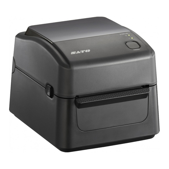
Understand Your Printer Perspective View 1 Understand Your Printer This chapter provides an overview of your printer. 1.1 Perspective View LED 2 LED 1 Feed Button Cover Open Latch WS4-DT-r01-30-12-16TM... -
Page 6: Back View
Understand Your Printer Back View 1.2 Back View Standard Model Paper Slot Power Switch RS232 USB A USB B Power Jack Caution The areas indicated by the ellipse have sharp edges. To avoid injury, be careful not to touch them when handling the printer. Caution To avoid injury, be careful not to trap your fingers in the paper slot while opening or closing the top cover. -
Page 7: Interior View
Understand Your Printer Interior View 1.3 Interior View Thermal Printhead Transmissive Sensor Core Holders Media Roll Holders Media Guides Thumbscrew Reflective Sensor Platen Roller Warning The printhead becomes very hot during printing. Do not touch the printhead or touch around it directly after printing. By doing so you may get burnt. -
Page 8: Printer Button And Lights
1 Understand Your Printer Printer Button and Lights 1.4 Printer Button and Lights This section describes the functions of your printer button and lights. 1.4.1 Feed Button The FEED button is not simply for feeding label. It is able to act as a feed, pause, resume, restore and run button. - Page 9 Understand Your Printer Printer Button and Lights LED indicate LED 2 LED 1 Description Label Green Green The printer is ready to print. Green ** Green The printer is transmitting data. * Green * Green In pause. * Green The printer is writing data to the flash or USB memory. Green * The USB memory is being initialized.
-
Page 10: Accessories Installation
2 Accessories Installation Cutter 2 Accessories Installation This chapter describes how to install accessories on your printer. 2.1 Cutter A cutter is used to cut the label after it is printed out. Full cutter cuts a label off from a media roll. To install a full cutter: Step 1. - Page 11 Accessories Installation Cutter 6. Lift the base and unplug all the cables. 7. Remove the base and the middle frame. Step 2. Connect the cutter to the main board This part describes how to thread the cutter cable and wire and connect them to the main board.
- Page 12 2 Accessories Installation Cutter 1. Locate two clasps on both sides of the platen roller. Slightly press them inward and rotate them 90 degrees, so the handles of the clasps point up. 2. Lift the platen roller. 3. Align the two screw holes of the cutter with the screw holes on both sides of the platen roller and fit the cutter dowel (at the bottom of the cutter) into the square hole on the middle frame.
-
Page 13: Dispenser
2 Accessories Installation Dispenser 2.2 Dispenser A dispenser automatically removes the liner from the printed label. The dispenser sensor detects if a peeled label is taken away. To install a dispenser: Step 1. Remove the base and the middle frame This part describes how to dismantle your printer. - Page 14 Accessories Installation Dispenser 1. Thread the dispenser cable into the square hole beside the right side of the platen roller and slightly push the right dowel into the hole. 2. On the left side, gently press the dispenser to the right to give some space for the left dowel and slightly push the left dowel into the hole.
- Page 15 Accessories Installation Dispenser 4. Close the dispenser and thread the cable into the lower square hole. 5. Turn over your printer. 6. Reinstall the middle frame. 7. Plug the dispenser connector to J14, which is the red port located to the right of the main board.
-
Page 16: Wireless Lan Module
Accessories Installation Wireless LAN Module 2.3 Wireless LAN Module The Wireless LAN module provides Wireless LAN connectivity for your printer. To install a Wireless LAN module: Step 1. Remove the base and the middle frame This part describes how to dismantle your printer. 1. - Page 17 Accessories Installation Wireless LAN Module 3. On the right side of your printer, find two screw holes under the top cover switch, align the two holes on the Wireless LAN card with them and secure the card with two screws. 4.
- Page 18 Accessories Installation Wireless LAN Module 6. Paste the foam pad to the surface behind the Wireless LAN antenna card. 7. Use the clip to fasten the Wireless LAN antenna card and the foam pad. 8. Attach the antenna to the Antenna port. The figures below show the correct (left) and incorrect (right) wiring.
- Page 19 2 Accessories Installation Wireless LAN Module ✔ ✘ 9. Reinstall the middle frame. 10. Plug the Wireless LAN cable 1 (white connector) to J13, which is the white port located to the lower-right of the main board. 11. Plug the Wireless LAN cable 2 (black connector) to J15, which is the black port located to the lower-right of the main board.
-
Page 20: Bluetooth Module
Accessories Installation Bluetooth Module 2.4 Bluetooth Module The Bluetooth module provides Bluetooth connectivity for your printer. To install a Bluetooth module: Step 1. Dismantle your printer This part describes how to remove the base and the middle frame. 1. Open the top cover. 2. - Page 21 Accessories Installation Bluetooth Module 3. Reinstall the middle frame. 4. Plug the Bluetooth cable to J15, which is the black port located to the lower-right of the main board. Step 3. Reinstall the base and the tear bar This part describes how to reinstall the parts you took off. 1.
-
Page 22: External Unwinder
2 Accessories Installation External Unwinder 2.5 External Unwinder An external unwinder can hold up to 8-inch outer diameter media roll. It allows you to print labels without frequently replacing media rolls. To install an external Unwinder: 1. Slide the Unwinder Holders into the Holder Slots, until the holders snap into the place. - Page 23 2 Accessories Installation External Unwinder If the inside diameter of the media roll is 1-inch, make sure the Core Holders ● are facing inward, and then insert the Roll Stops into each end of the Holder Shaft. If the inside diameter of the media roll is 3-inch, make sure the Core Holders ●...
-
Page 24: System Mode
3 System Mode 3 System Mode The system mode consists of status light color combinations. It contains a list of commands for you to select and run. To enter the system mode and run the command, do the following: 1. Turn off your printer. 2. -
Page 25: Media Sensor Calibration
Each type of media roll has its own label separators, such as gaps, holes, notches or black marks. Those separators need to be detected by media sensors, so the label can be printed in correct position. SATO WS4 DT printers provide transmissive and reflective sensor calibration for media detection. Do the following to use them. -
Page 26: Reset Your Printer
System Mode Reset Your Printer 3.2 Reset Your Printer By resetting your printer, you can return your printer to the state it was in when you receive it. This can help you solve some problems caused by settings changed during the printing. Do the following to reset your printer: 1. -
Page 27: Self-Test And Dump Mode
Self-Test and Dump 3 System Mode mode 3.3 Self-Test and Dump Mode Your printer can run a self-test to print a configuration label, which helps you understand the current settings of your printer. 3.3.1 Self-Test 1. Turn off your printer. 2. - Page 28 System Mode Self-Test and Dump mode SBPL ■ WS4-DT-r01-30-12-16TM...
- Page 29 Self-Test and Dump 3 System Mode mode 1. Version Information The firmware version and its build date. 2. Standard RAM Total SDRAM size. 3. Available RAM RAM is able to be used. 4. Flash Type The flash memory type and size. 5.
- Page 30 Self-Test and Dump 3 System Mode mode 19. Cut Count It counts the times the cutter cuts. 20. RS232 Protocol It lists RS-232C settings in the following order: baud rate, data length, parity check, stop bit and flow control. 21. Media The media type in use.
- Page 31 Self-Test and Dump 3 System Mode mode 34. SNMP When it is enabled, the host gets or sets parameters registered as SNMP entities. 35. Socket Communication When it is enabled, the host communicates with your printer via the socket. 36. Socket Port The socket number of your printer.
- Page 32 System Mode Self-Test and Dump mode If your printer has a Wireless LAN module, your SBPL configuration label will contain the following entries: 1. FW Version and Date Wireless LAN card firmware version and date. 2. IP Address The IP address of your printer. When DHCP is enabled, it shows the automatically assigned IP address;...
- Page 33 System Mode Self-Test and Dump mode 9. SSID Short for service set identifier. It is the name of a wireless local area network. 10. Mode It determines how you connect your printer to a network. Infrastructure: If you connect through an access point, select this. Ad hoc: if you connect through a device which has connected to a network, select this.
- Page 34 System Mode Self-Test and Dump mode SZPL ■ WS4-DT-r01-30-12-16TM...
- Page 35 Self-Test and Dump 3 System Mode mode 1. Version Information The firmware version and its build date. 2. Standard RAM Total SDRAM size. 3. Available RAM RAM is able to be used. 4. Flash Type The flash memory type and size. 5.
- Page 36 Self-Test and Dump 3 System Mode mode 18. Print Method It is direct thermal printing. 19. Print Length The total print length. 20. Cut Count It counts the times the cutter cuts. 21. RS232 Protocol It lists RS-232C settings in the following order: baud rate, data length, parity check, stop bit and flow control.
- Page 37 Self-Test and Dump 3 System Mode mode The unique address assigned to your printer that connects to the internet. 36. DHCP When DHCP is enabled, it assigns an IP address to your printer automatically. 37. DHCP Client ID It is an arbitrary value sent to the DHCP server to reserve an IP address for your printer.
- Page 38 System Mode Self-Test and Dump mode 53. Reflective Sensor Offset For developers to debug. 54. See-Through Sensor Offset For developers to debug. 55-63. Font Image You can use them as the reference to check your label font. 64-69. TPH Test Pattern You can use them to check broken pins on the printhead.
- Page 39 Self-Test and Dump 3 System Mode mode Short for service set identifier. It is the name of a wireless local area network. 7. Country Code The country or region. 8. Channel The Wireless LAN channel. 9. Join It determines how you connect your printer to a network. It’s either AP (Access Point) or Ad hoc.
- Page 40 System Mode Self-Test and Dump mode SDPL ■ WS4-DT-r01-30-12-16TM...
- Page 41 System Mode Self-Test and Dump mode SEPL ■ WS4-DT-r01-30-12-16TM...
- Page 42 System Mode Self-Test and Dump mode SIPL ■ WS4-DT-r01-30-12-16TM...
-
Page 43: Dump Mode
To return to the online mode: Turn off your printer and turn it on again. ■ In SATO WS4 Printer Utility, in the Navigation pane, click Tool. In the ■ Properties pane, click Reboot Printer and click Send. This is applicable for SZPL, SDPL and SEPL. -
Page 44: Sato Ws4 Printer Utility
You can define properties, update firmware and send commands in SATO WS4 Printer Utility. 4.1 Install SATO WS4 Printer Utility 1. Download the SATO WS4 Settings utility from your local SATO Resources website and start the installation process. 2. Locate the installation file on the CD and click it. - Page 45 4 SATO WS4 Printer Utility Install SATO WS4 Printer Utility 4. In this dialog box, follow the instructions to choose the installation path and then click Next. 5. In this dialog box, click Next.
- Page 46 4 SATO WS4 Printer Utility Install SATO WS4 Printer Utility 6. After the installation of SATO WS4 Printer Utility is complete, click Close.
-
Page 47: Work With Sato Ws4 Printer Utility
4 SATO WS4 Printer Utility Work with SATO WS4 Printer Utility 4.2 Work with SATO WS4 Printer Utility Start SATO WS4 Printer Utility. Its interface looks like this: Menu bar It includes SATO WS4 Printer Utility menus. ■ Toolbar It provides ports, port settings, emulation languages, printer dpi and ■... - Page 48 Auto Detect USB When you connect your printer ■ to a computer with a USB cable, SATO WS4 Printer Utility automatically detects it and shows the USB information in the Port Name and Port Information. By default, it is enabled.
-
Page 49: Toolbar
4 SATO WS4 Printer Utility Work with SATO WS4 Printer Utility Language ■ It is the language of SATO WS4 Printer Utility interface. You can select Windows’s System Default, English or Simplified Chinese. By default, it uses your system default. Help Contents The help content of SATO WS4 Printer Utility. - Page 50 4 SATO WS4 Printer Utility Work with SATO WS4 Printer Utility ■ It shows the USB information in the Port Name and Port Information as soon as the computer detects your printer. By default, the computer automatically detects the USB port.
-
Page 51: Printer Status
4 SATO WS4 Printer Utility Work with SATO WS4 Printer Utility connection Set up WLAN connection. The second row of the toolbar includes six items. Printer Model Printer models. ■ Printer Emulation The emulation language of your printer. The emulation ■... -
Page 52: Navigation Pane
SATO WS4 Printer Utility Work with SATO WS4 Printer Utility Description CUTTER ERROR The cutter is experiencing issues. NO PAPER The label has run out. HEAD OPEN Attempt to feed or issue the label with the top cover (head) ERROR open. - Page 53 (Some of them only have Send). Send is to send your settings to your 4 SATO WS4 Printer Utility Work with SATO WS4 Printer Utility printer; Get is to get the current settings of your printer; Add is to add file to the...
-
Page 54: Parameter Setting
SATO WS4 Printer Utility Work with SATO WS4 Printer Utility list object; Delete is to delete file from the list object. You can also right-click in the Properties pane and select Send, Get, Add or Delete in the shortcut menu. - Page 55 4 SATO WS4 Printer Utility Work with SATO WS4 Printer Utility Property Name Description Sensor Type It is the media sensor you are using. It includes I-MARK, GAP and None. When you perform media calibration, the sensor is set to the one you select.
- Page 56 4 SATO WS4 Printer Utility Work with SATO WS4 Printer Utility Property Name Description ON (Power on and Head close) Your printer automatically calibrates media using a media sensor after power on and every time you close the print module when the printer is turned on.
- Page 57 4 SATO WS4 Printer Utility Work with SATO WS4 Printer Utility Property Name Description Inch Change the unit of Position Adjustment to inch. dots Change the unit of Position Adjustment to dots. Horizontal Offset Move the print position horizontally. The positive number is left, and the negative number is right.
- Page 58 4 SATO WS4 Printer Utility Work with SATO WS4 Printer Utility SDPL, SEPL, SIPL, SZPL and AUTO ■ SDPL, SEPL, SIPL, SZPL and AUTO provides settings grouped in the Supply, Control, Action, Label and Position Adjustment area. Property Name Description Sensor Type It is the media sensor you are using.
- Page 59 4 SATO WS4 Printer Utility Work with SATO WS4 Printer Utility Property Name Description media using a media sensor every time you close the print module when the printer is turned on. ON (Power on and Head close) Your printer...
- Page 60 4 SATO WS4 Printer Utility Work with SATO WS4 Printer Utility mm/inch/dot conversion process in Position Adjustment is as follows; Input to the form in Setting Tool Unit Value Setting condition The value is adjustable in increments of ± 0.1 mm and rounded to the 1st decimal place.
- Page 61 4 SATO WS4 Printer Utility Work with SATO WS4 Printer Utility The COM tab provides the settings of the RS-232C port. When you use COM as your port, make sure the settings in the COM tab are the same as the port settings, or your printer won’t work properly.
- Page 62 4 SATO WS4 Printer Utility Work with SATO WS4 Printer Utility sends an XOFF signal to tell the computer to stop sending data; once your printer is able to accept data, it sends an XON signal to notify the computer to resume sending data.
- Page 63 4 SATO WS4 Printer Utility Work with SATO WS4 Printer Utility The LAN tab provides network settings, including TCP/IP, Current TCP/IP, Protocol, Server and SNMP Trap. Property Name Description IP Address (TCP/IP) The static IP address of your printer. Subnet Mask (TCP/IP) The manually specified subnet mask of your printer.
- Page 64 4 SATO WS4 Printer Utility Work with SATO WS4 Printer Utility Property Name Description manually. Host Name It is the name of a DHCP client. The host name allows up to 32 alphanumeric characters. You can leave it blank or type a name you want. By default, there is no host name.
- Page 65 4 SATO WS4 Printer Utility Work with SATO WS4 Printer Utility Set up LAN connection If you want to use the LAN port to transfer data, you need to set up the network connection in the LAN tab. 1. Connect your printer and computer to a network device (hub, switch or router) with Ethernet cables.
- Page 66 4 SATO WS4 Printer Utility Work with SATO WS4 Printer Utility If you don’t have a static IP address, make sure DHCP is enabled and click ● Send. 5. After your printer restarts, click Get to get the TCP/IP information of your printer.
- Page 67 SATO WS4 Printer Utility Work with SATO WS4 Printer Utility If you are using a dynamic IP ● address provided by DHCP, in the IP Address box, enter the IP address under Current TCP/IP in the LAN tab, and then click OK.
- Page 68 4 SATO WS4 Printer Utility Work with SATO WS4 Printer Utility IPv6 The IPv6 tab provides IPv6 settings, including IPv6 and Current IPv6. Property Name Description Mode It determines how you get the IPv6 address of your printer. MANUAL Specify an IPv6 address manually.
- Page 69 4 SATO WS4 Printer Utility Work with SATO WS4 Printer Utility Property Name Description that generates the second half of a unicast IPv6 address (last 64 bits) from a MAC address. You can also specify the second half of the address by entering the interface ID.
- Page 70 4 SATO WS4 Printer Utility Work with SATO WS4 Printer Utility 2. After your printer restarts, click Get to get its IPv6 information. If you are using a static IPv6 address, you’ll get the same settings as it is in the previous step; if you are using DHCPv6, the DHCPv6 server will automatically populate the IP Address and Link-Local Address boxes under Current IPv6.
- Page 71 SATO WS4 Printer Utility Work with SATO WS4 Printer Utility If you are using a dynamic IP address ● provided by DHCPv6, in the IP Address box, enter the IP address under Current IPv6 in the IPv6 tab and click...
- Page 72 4 SATO WS4 Printer Utility Work with SATO WS4 Printer Utility Property Name Description IP Address (IPv4) The static IPv4 address of your printer. The manually specified IPv4 subnet mask of Subnet Mask (IPv4) your printer. The manually specified IPv4 gateway of your Gateway (IPv4) printer.
- Page 73 4 SATO WS4 Printer Utility Work with SATO WS4 Printer Utility Property Name Description WPA2-Enterprise WPA2-Enterprise includes all features of WPA-Enterprise, but it uses AES encryption to enhance security. Turn on WEP encryption. Turn off WEP encryption. WEP Key Index The default key of WEP.
- Page 74 4 SATO WS4 Printer Utility Work with SATO WS4 Printer Utility Property Name Description characters excluding double quotation marks (“). Pre-shared key authentication is for home or small offices. Module Restore Default It resets all values in the Wireless LAN module.
- Page 75 4 SATO WS4 Printer Utility Work with SATO WS4 Printer Utility Property Name Description the WEP key for each session, preventing attackers retrieving data by cracking the key. EAP-TLS TLS stands for Transport Layer Security. EAP-TLS requires both a client and a server to exchange digital certificates to authenticate each other.
- Page 76 4 SATO WS4 Printer Utility Work with SATO WS4 Printer Utility Set Up WLAN Connection Before you set up a wireless LAN connection, make sure your computer has connected to a wireless network. 1. In the Input/Output Port list, click USB or COM.
- Page 77 4 SATO WS4 Printer Utility Work with SATO WS4 Printer Utility If you’re using Open and WEP is on, choose your WEP password type in the WEP ● Input Type list. Next, enter your WEP password in one of the WEP Key box, and select the key you want to use from the WEP Key Index list.
- Page 78 4 SATO WS4 Printer Utility Work with SATO WS4 Printer Utility 4. Do one of the following to configure your IPv4 settings: If you have a static IP address, fill the IP Address, Subnet Mask and Gateway ● box under IPv4 according to your network settings, make sure DHCP is disabled and click Send.
- Page 79 4 SATO WS4 Printer Utility Work with SATO WS4 Printer Utility 6. In the Input/Output Port list, click LAN, and click Setting. 7. In the Setting LAN dialog box, do one of the following to configure your IP address: If you are using a static IP address, in ●...
- Page 80 4 SATO WS4 Printer Utility Work with SATO WS4 Printer Utility Bluetooth The Bluetooth tab provides Bluetooth settings. Property Name Description Pin Code The Bluetooth PIN code of your printer. The new PIN code takes effect when you reconnect your printer to your computer.
- Page 81 4 SATO WS4 Printer Utility Work with SATO WS4 Printer Utility Reset Parameter Setting If you want to reset Parameter Setting, do this: 1. In Parameter Setting, right-click in the blank area in any tab. 2. In the shortcut menu, do one of the following...
- Page 82 Set up IPv6 connection Set up WLAN connection. Firmware The Firmware tab displays in all emulation modes. It is used to update firmware. For information about update firmware in SATO WS4 Printer Utility, see Update firmware in SATO WS4 Printer Utility. General The General tab displays in all emulation modes.
- Page 83 4 SATO WS4 Printer Utility Work with SATO WS4 Printer Utility 4. Click Download in the Navigation pane. 5. Under the General tab, right-click in the blank area and click Add.
- Page 84 4 SATO WS4 Printer Utility Work with SATO WS4 Printer Utility 6. In the Open dialog box, browse to the folder that contains command files, select them and click Open. The command files you select must correspond to the emulation language you use.
- Page 85 SATO WS4 Printer Utility Work with SATO WS4 Printer Utility 8. Click Send to run the command on your printer. Note If you send a command file and your printer doesn’t respond, it is possible that the emulation language is not set correctly. Click Sync to get the current setting of Printer Emulation.
- Page 86 4 SATO WS4 Printer Utility Work with SATO WS4 Printer Utility Turn on Ribbon Calibration. Enter the height of your label in the scale • box. For example, if the height of your label is 100 mm, enter 100 in the...
-
Page 87: Update Firmware
5.1 Update Firmware in SATO WS4 Printer Utility This section describes how to update printer firmware in SATO WS4 Printer Utility. 5.1.1 Update via the USB or COM Port 1. Connect your printer and the computer with a USB or a serial cable. - Page 88 5 Update Firmware Update Firmware in SATO WS4 Printer Utility 5. In the Navigation pane, click Download and click the Firmware tab.
- Page 89 5 Update Firmware Update Firmware in SATO WS4 Printer Utility 6. Right-click in the blank area and click Add. 7. In the Open dialog box, browse to the folder that contains the firmware files. Select all of them and click Open.
- Page 90 5 Update Firmware Update Firmware in SATO WS4 Printer Utility 8. If you want to update specific files, select the check boxes of those files; if you want to update all of the firmware files, right-click in the blank area in the list, and click Select All.
- Page 91 5 Update Firmware Update Firmware in SATO WS4 Printer Utility 10. When the data transmission is complete, your printer starts to update its firmware. During the update, LED 2 turns to red and orange alternatively, while LED 1 turns to solid green. In the Download Firmware dialog box, the message shows that your printer is updating the firmware.
-
Page 92: Update Via The Lan Port
1. Make sure the print module is closed. 2. Turn on your printer, and start SATO WS4 Printer Utility. 3. In the Input/Output Port list, click LAN, and do one of the following: If you are using the LAN port, the Port Name and Port Information will show ●... - Page 93 5 Update Firmware Update Firmware in SATO WS4 Printer Utility IPv6 WLAN 4. In the Navigation pane, click Download and click the Firmware tab. 5. Right-click in the blank area and click Add.
- Page 94 5 Update Firmware Update Firmware in SATO WS4 Printer Utility 6. In the Open dialog box, browse to the folder that contains the firmware files. Select all of them and click Open. 7. If you want to update specific files, select the check boxes of those files; if you want to update all of the firmware files, right-click in the blank area in the list, and click Select All.
- Page 95 5 Update Firmware Update Firmware in SATO WS4 Printer Utility 8. Click Send to send the firmware files to your printer. During the transmission, LED 1 blinks green. In the Download Firmware dialog box, the message shows the file your printer is downloading, and the progress bar indicates the progress of downloading.
- Page 96 5 Update Firmware Update Firmware in SATO WS4 Printer Utility 10. Printer will restart automatically after the message “Firmware Update, Succeed” appears. 11. When the update is complete, the message “Firmware Update Complete” appears. At the same time, your printer restarts itself. Click Close to close the...
-
Page 97: Update Firmware Via The Usb Host
5 Update Firmware SATO WS4 Printer Utility 5.2 Update Firmware via the USB Host The USB host is a USB type A port for a USB flash drive, which can be used to quickly update the firmware. 1. Create a folder named “Firmware” in your USB flash drive, and copy the firmware files to it. -
Page 98: Update Firmware In Atmel Mode
Service Engineer only Typically, firmware can be updated in SATO WS4 Printer Utility without problems, but there are rare cases SATO WS4 Printer Utility cannot handle. If any unexpected conditions keep you from update firmware in SATO WS4 Printer Utility, you need to update it in Atmel mode. - Page 99 5 Update Firmware Update Firmware in Atmel Mode 3. Start SATO WS4 Printer Utility. In the Navigation pane, click Download and click the Firmware tab. 4. Right-click in the blank area and click Add.
- Page 100 5 Update Firmware Update Firmware in Atmel Mode 5. In the Open dialog box, browse to the folder that contains WS4 firmware files. Select all of them and click Open. 6. Right-click in the blank area in the list and click Select All to select all of the check boxes.
- Page 101 5 Update Firmware Update Firmware in Atmel Mode 7. Click Send to send the firmware files to your printer. When the update is complete, the message “Done” appears. Click Close to close the dialog box or click Save Log to save the firmware update log. Step 3.
-
Page 102: Troubleshooting
6 Troubleshooting Cutter and Dispenser Issues 6 Troubleshooting This chapter provides the information about accessories issues, internal errors and their possible solutions. 6.1 Cutter and Dispenser Issues Issue Solution If there is a paper jam, clear it. ■ The cutter has become loose. Fix the ■... -
Page 103: Internal Errors
Make sure the serial cable is connected ■ properly and the computer is turned on. In SATO WS4 Printer Utility, the settings ■ Communication error (RS-232C). of the COM port need to be the same as those in the COM tab in Parameter. - Page 104 6 Troubleshooting Internal Errors Error Solution than the boundary of the long word data. An undefined command in a place other than the delay slot has been decoded. An undefined command in the delay slot has been decoded. A command which rewrites the data in the delay slot has been decoded.
-
Page 105: Network
Network Network Architecture 7 Network This chapter provides the information about your printer networking. 7.1 Network Architecture As the figure shows, the network architecture includes several layers, and each layer corresponds to the layer in the Open Systems Interconnection (OSI) model. The print engine is on the application layer. - Page 106 7 Network Network Architecture IP is the commonly used protocol in the network layer. It defines an address system and provides end-to-end communication for data transmission. The packet is delivered based on the IP address in the IP header, which is attached to the packet.
-
Page 107: Ethernet Status Indicators
Network Ethernet Status Indicators 7.2 Ethernet Status Indicators Indicator Status Description Note Green Speed 100 Mbps When both LEDs are off, there is no Ethernet 10 Mbps connection. Amber Link Link Up Activity Link Down Blink Activity Green LED Amber LED... -
Page 108: Specifications
8 Specifications Printer 8 Specifications This chapter provides specifications of your printer. Specifications are subject to change without notice. 8.1 Printer Model WS408DT WS412DT Print method Direct Thermal Resolution 203 dpi (8 dots/mm) 300 dpi (12 dots/mm) Media Alignment Centered... - Page 109 Specifications Printer WS412DT Standard Memory (Flash ROM): 16 MB User Memory: 3 MB Onboard Memory Standard Memory (SDRAM): 32 MB External Memory USB: Max 16 GB Panel 2 LED, 1 Button LED: Red and Green (Various Combinations: Orange) LED: Red and Green (Various Combinations: Orange) Bitmap: XS, XU, XM, XB, XL, OCR-A, OCR-B Font Scalable: CG Times, CG Triumvirate...
-
Page 110: Media
8 Specifications Bar Code 8.2 Media Properties Description Media Size Continuous Mode Length: 8 mm ~ 996 mm (including liner 11mm~999mm) Width: 22.4 mm ~ 115 mm (including liner 25.4 ~ 118 mm) Tear-Off Mode Length: 30 mm ~ 996 mm (including liner 33mm~999mm) Width: 22.4 mm ~ 115 mm (including liner 25.4 ~ 118mm) Dispenser Mode Length: 35 mm ~ 150.4 mm (including liner 38mm~153.4mm) -
Page 111: Bar Codes
8 Specifications Bar Code 8.3 Bar Codes Programming Language SZPL\SDPL\SEPL One Dimensional Bar UPC-A Code UPC-E JAN/EAN CODE39 CODE93 CODE128 GS1-128 (UCC/EAN128) CODABAR (NW-7) Industrial 2of5 UPC add-on code POSTNET GS1 DataBar Omnidirectional GS1 DataBar Truncated GS1 DataBar Stacked GS1 DataBar Stacked Omnidirectional GS1 DataBar Limited GS1 DataBar Expanded GS1 DataBar Expanded Stacked... - Page 112 Specifications Bar Code Programming Language SZPL\SDPL\SEPL GS1 DataBar Expanded Composite (CC-A/CC-B) GS1 DataBar Stacked Omnidirectional Composite (CC-A/CC-B) GS1 DataBar Limited Composite (CC-A/CC-B) GS1-128 Composite (CC-A/CC-B/CC-C)
-
Page 113: Wireless Lan
Specifications Wireless LAN 8.4 Wireless LAN Wireless LAN I/F Protocol Hardware IEEE802.11b/g/n Enabled Device WS4 Series Operating -4 degF (-20 degC) ~ 185 degF (+85 degC) Temperature Destination Europe Frequency 2412 ~ 2462 MHz 2412 ~ 2472 MHz (Center Channel) Channel 1 ~ 11 ch 1 ~ 13 ch... - Page 114 39M / 43.3M / 52M / 57.8M / 58.5M / 65M / 8 Specifications Wireless LAN...
- Page 115 Specifications Wireless LAN Wireless LAN I/F 72.2M(Auto-sensing) Antenna External antenna Aerial power 802.11b Max +15 dBm 802.11g Max +17 dBm 802.11n Max +17 dBm Softw are Connection mode Infrastructure, Adhoc Default IP Address 192.168.1.1 Default Subnet Mask 255.255.255.0 Default ESSID SATO_PRINTER Default DHCP Enable...
-
Page 116: Bluetooth
8 Specifications Bluetooth 8.5 Bluetooth Properties Bluetooth I/F Standard Bluetooth 2.1 + EDR or later Enable Device WS4 Series Operating Temperature 41°F (5°C) ~ 104°F (40°C) Storage Temperature -4°F (-20°C) ~ 140°F (60°C) Operating Humidity 25 ~ 85 % Non-condensing R.H Storage Humidity 10 ~ 90 % Non-condensing R.H Connection Form... -
Page 117: Ethernet
8 Specifications Ethernet 8.6 Ethernet Properties Description Port RJ-45 Speed 10Base-T/100Base-T (Auto Detecting) Protocol ARP, IP, ICMP, UDP, TCP, HTTP, DHCP, Socket, LPR, IPv4, SNMPv2 Mode TCP Server/Client, UDP Client Technology HP Auto-MDIX, Auto-Negotiation 8.7 Electrical and Operating Environment Properties Range Power Supply Voltage: AC 100 V ~ 240 V ±... -
Page 118: Interfaces
Technical Drawings Technical Drawings 8.9 Interfaces This section provides information about IO port specifications for your printer. 8.9.1 USB Your printer has two USB ports: type A and type B. Typically, type A is found on computers and hubs; type B is found on devices and hubs. The figure below shows their pinouts. -
Page 119: Ethernet
Technical Drawings Technical Drawings 8.9.2 Ethernet The Ethernet uses RJ-45 cable, which is 8P8C (8-Position 8-Contact). The figure below shows its pinout. 1 2 3 4 5 6 7 8 Signal Transmit+ Transmit- Receive+ Reserved Reserved Receive- Reserved Reserved... -
Page 120: Rs-232C
Technical Drawings Technical Drawings 8.9.3 RS-232C The RS-232C on your printer is DB9 female. It transmits data bit by bit in asynchronous start-stop mode. The figure below shows its pinout. 9 8 7 6 Signal Description Provide 5V Power Receive Transmit No Connection Ground... - Page 121 9 Technical Drawings Technical Drawings Host (DB9) Printer (DB9) Signal Description Description Signal Carrier Detect Provide 5V Power Receive Receive Transmit Transmit Data Terminal Ready No Connection Ground Ground Data Set Ready Pull High Request to Send Request to Send Clear to Send Clear to Send Pull High...
-
Page 122: Technical Drawings
9 Technical Drawings Technical Drawings 9 Technical Drawings This chapter provides technical drawings of your printer. 9.1 Main Board Diagram Main Board A printed circuit board assembly (PCBA) consists of a microcontroller, flash memory, SDRAM and more. Panel A two-layer PCBA consists of one button and two LEDs. Media Sensor A two-layer PCBA consists of a reflective and a transmissive sensor, which is designed for media detection. - Page 123 9 Technical Drawings Technical Drawings Thermal Printhead (TPH) It consists of a line of tiny resistors that is electronically controlled to produce heat for printing. For direct thermal printing, a TPH directly heats up an area of the thermal paper to produce an image. Stepper Motor A stepper motor rotates certain degrees in each step-in response to an electronic pulse.
-
Page 124: System Diagram
System Diagram System Diagram 9.2 System Diagram Communication Port RS232 / USB Host USB Device / LAN / BT / Wireless LAN Power System 24V, 5V, 3V3, 1V8 Sensor System Memory System Transmissive Sensor Flash ROM Reflective Sensor SDRAM KEYPAD Printhead System LED MARTIX MOTOR Driver... - Page 125 9 System Diagram System Diagram Microcontroller (U11) The microcontroller (MCU) is AT91SAM9260. The MCU is like a microcomputer which integrates CPU, memory, I/O ports, timers and other components. The CPU it uses is ARM926-based processor. Flash memory (U18) The flash memory stores firmware, graphics, label formats, soft fonts and BASIC files.
-
Page 126: Wiring Diagram
Wiring Diagram Wiring Diagram 9.3 Wiring Diagram... -
Page 127: Appendix A: Dip Switch
Appendix A DIP switch Appendix A: DIP Switch DIP Switch Description Description Default Switch between the ON: Firmware mode. It firmware mode and boots your printer from Atmel mode. the flash memory. OFF: Atmel mode. It boots your printer from CPU ROM.
Need help?
Do you have a question about the WS408DT and is the answer not in the manual?
Questions and answers
The green lever with a spring came undone and we are trying to get it back together, but can't seem to find anything that shows how it goes together.
How do I make my SATO WS 408DT unit wireless please?
How do get it to print one side, instead of two in a tiny ticket