
Related Manuals for Keithley SourceMeter 2790


Summary of Contents for Keithley SourceMeter 2790
- Page 1 Model 2790 SourceMeter ® Switch System Reference Manual 2790-901-01 Rev. E / August 2011...
- Page 2 ® Model 2790 SourceMeter Switch System Reference Manual ©2011, Keithley Instruments, Inc. All rights reserved. Cleveland, Ohio, U.S.A. Document Number: 2790-901-01 Rev. E...
- Page 4 Service personnel are trained to work on live circuits, perform safe installations, and repair products. Only properly trained service personnel may perform installation and service procedures. Keithley Instruments products are designed for use with electrical signals that are rated Measurement Category I and Measurement Category II, as described in the International Electrotechnical Commission (IEC) Standard IEC 60664.
- Page 5 themselves from the risk of electric shock. If the circuit is capable of operating at or above 1000V, no conductive part of the circuit may be exposed. Do not connect switching cards directly to unlimited power circuits. They are intended to be used with impedance- limited sources.
- Page 6 (note that selected parts should be purchased only through Keithley Instruments to maintain accuracy and functionality of the product). If you are unsure about the applicability of a replacement component, call a Keithley Instruments office for information.
-
Page 8: Table Of Contents
Table of Contents Getting Started General information ..............Contact information ............Safety symbols and terms ........... Inspection ................Options and accessories ............Model 2790 features ..............Plug-in switching modules ............Pseudocards ................ Identifying installed switching modules ......Power supply restrictions with the 7753 module ....Front and rear panel familiarization (QS1) ........ - Page 9 Channel assignments ..............System channel operation (7702 only) ........2-wire functions ..............4-wire functions (paired channels) ........Controlling the system channel ........... Multiple channel operation ............2-13 Controlling multiple channels ........... 2-14 Multiple channel operation anomalies (7702 only) ... 2-19 Dual independent multiplexers (7702 only) ......
- Page 10 Low level considerations ........... 3-12 Current measurements (DCI and ACI) ........3-13 Connections ..............3-14 Amps measurement procedure .......... 3-15 AMPS fuse replacement (front panel AMPS input) ..3-16 Resistance measurements (Ω2 and Ω4) ........3-16 Connections ..............3-17 Standard resistance measurements ........3-19 Offset-compensated ohms ..........
- Page 11 Rate and bandwidth ..............Rate ..................Bandwidth ................. 4-10 Scanning (7702 only) ............4-10 Remote programming — rate and bandwidth ....4-10 Filter ..................4-13 Filter characteristics ............4-13 Remote programming — filter .......... 4-18 Relative, Math, Ratio, Channel Average, and dB Relative ..................
- Page 12 Scan configuration (7702 only) ..........7-11 Scan reset ................7-13 Simple scan ............... 7-14 Advanced scan ..............7-15 Setting delay ..............7-18 Monitor channel ..............7-18 Auto channel configuration ..........7-20 Saving setup ..............7-20 Auto scan ................7-21 Scan operation (7702 only) ............7-21 Basic scan .................
- Page 13 Limits ..................Front panel scanning (7702 only) ........Remote scanning ..............Basic limits operation ............Digital I/O ................... Digital input (trigger link input) .......... Digital outputs ..............Setting digital output ............9-11 Scanning ................9-12 Remote programing — limits and digital output ...... 9-13 Limits and digital output commands .........
- Page 14 Case sensitivity ............... 10-13 Long-form and short-form versions ........ 10-13 Short-form rules .............. 10-13 Program messages ............10-14 Response messages ............10-16 Message exchange protocol ..........10-17 RS-232 interface operation ............ 10-17 Sending and receiving data ..........10-17 Baud rate ................. 10-17 Signal handshaking (flow control) ........
- Page 15 READ? ..................13-7 MEASure:<function>? [<rang>], [<res>], [<clist>] ....13-8 FORMat and Miscellaneous SYSTem Commands FORMat commands ..............14-2 FORMat[:DATA] <type>[,<length>] ....... 14-2 FORMat:ELEMents <item list> ........14-6 FORMat:BORDer <name> ..........14-7 Miscellaneous SYSTem commands ......... 14-8 SYSTem:PRESet ............... 14-8 SYSTem:VERSion ............14-8 SYSTem:KEY <NRf>...
- Page 16 Verifying AC current ............16-23 Verifying resistance ............16-24 Verifying temperature ............. 16-26 Verifying frequency ............16-27 Verifying ratio and average ..........16-28 Model 7751, 7752, and 7753 verification ......16-28 Recommended test equipment ........16-29 Verifying the current source ..........16-30 Verifying the voltage source (Model 7751 and 7753 only) 16-31...
- Page 17 Replacing Model 7702 plug-in module amps fuses ....18-5 Replacing Model 7751/7752/7753 plug-in module fuses ..18-6 Replacing non-volatile RAM battery ........18-8 Plug-in module relay closure count .......... 18-9 Closure count commands ..........18-9 Reading relay closure count ..........18-10 Resetting relay closure count ..........
- Page 18 Radio frequency interference ..........Ground loops ..............Shielding ................Meter loading ..............D-10 Thermistor equation ..............RTD equation ................Introduction ................Bus description ................Bus lines ..................Data lines ................Bus management lines ............Handshake lines ..............Bus commands ................Uniline commands ..............
- Page 19 :STEP10 ................G-11 :STEP11 ................G-12 :STEP12 ................G-12 AC calibration commands ............G-13 :AC:STEP<n> ..............G-14 Manufacturing calibration commands ........G-15 :AC:STEP<14|15> ............G-15 :DC:STEP0 ............... G-15 Model 7751, 7752, and 7753 calibration commands ....G-16 :CODE ................G-17 :COUNt? ................
-
Page 20: Getting Started
• Model 2790 features — Summarizes the features of Model 2790. • Plug-in switching modules — Summarizes the capabilities of the Keithley Models 7702, 7751, 7752, and 7753 switching modules. QS1 • Front and rear panel familiarization — Summarizes the controls and connectors of the instrument. -
Page 21: General Information
Contact information Worldwide phone numbers are listed at the front of this manual. If you have any questions, please contact your local Keithley representative or call a Keithley Application Engineer at 1-800-348-3735 (U.S. and Canada only). Safety symbols and terms... -
Page 22: Options And Accessories
® Model 2790 SourceMeter Switch System Reference Manual If an additional manual is required, order the appropriate manual package. The manual packages include a manual and any pertinent addenda. Options and accessories Plug-in switching modules klqb The Model 2790 User’s Manual provides information specific to airbag module testing using the Models 7751, 7752, 7753, and 7702 switching modules. -
Page 23: Model 2790 Features
Section 5 of the Model 2790 User’s Manual. The Keithley 7702 is a multiplexing switching module. Each system channel that is closed or scanned is measured by the Model 2790 DMM. For scanning, each channel can have its... - Page 24 ® Model 2790 SourceMeter Switch System Reference Manual More information on the measurement capabilities of the Model 2790 is provided in “DMM measurement capabilities,” page 3-2. Specifications for the Model 2790 and the 7751, 7752, 7753, and 7702 switching modules are provided in Appendix Additional features of Model 2790 include: •...
-
Page 25: Plug-In Switching Modules
® Model 2790 SourceMeter Switch System Reference Manual Plug-in switching modules Up to two Keithley switching modules can be installed in the Model 2790. A side-by-side comparison of the switching modules is provided in Table 1-1. Basic close/open operation for switching module channels is provided in... -
Page 26: Pseudocards
Model 2790. This feature allows you to configure your system without having the actual switching module installed in the unit. There is a pseudocard for the Keithley Models 7751, 7752, 7753, and 7702 switching modules. For details, see “Pseudocards,” page 2-6. -
Page 27: Front And Rear Panel Familiarization (Qs1)
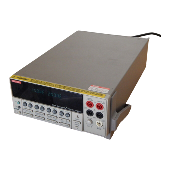
® Model 2790 SourceMeter Switch System Reference Manual Front and rear panel familiarization (QS1) Front panel summary The front panel of Model 2790 is shown in Figure 1-1. Figure 1-1 Model 2790 front panel SENSE INPUT Ω 4 WIRE 350V 1000V PEAK PEAK... - Page 28 ® Model 2790 SourceMeter Switch System Reference Manual 2 Function and operation keys: Top Row Unshifted Selects DC voltage measurement function. Selects AC voltage measurement function. Selects DC current measurement function. Selects AC current measurement function. Ω Selects 2-wire resistance measurement function. Ω...
- Page 29 ® 1-10 Model 2790 SourceMeter Switch System Reference Manual Shifted SAVE Saves up to four instrument setups for future recall and selects power-on setup. SETUP Restores a default setup (factory or *RST) or a saved setup. Enables/disables buffer auto clear, auto scan, and auto channel configuration. Sets timestamp, date, and time.
- Page 30 ® Model 2790 SourceMeter Switch System Reference Manual 1-11 5 INPUTS switch: Use to select front panel inputs (out; F) position or switching module inputs (in; R) position. klqb For remote programming, the following command queries the INPUTS switch position: SYSTem:FRSWitch? ' Query INPUTS switch;...
-
Page 31: Rear Panel Summary
100V/120V/220V/240VAC at line frequencies of 50 or 60Hz. 6 Slot 1 and Slot 2 Two slots to accommodate Keithley Model 7751, 7752, 7753, and 7702 switching modules. The Model 2790 is shipped from the factory with slot covers installed. Please note additional slot covers can be requested from Keithley Instruments. -
Page 32: Power-Up (Qs2)
NO INTERNAL OPERATOR SERVICABLE PARTS,SERVICE BY QUALIFIED PERSONNEL ONLY. DIGITAL I/O TRIG. LINK RS232 IEEE-488 MADE IN U.S.A. Fuse Line KEITHLEY Voltage SLOT COVER Selector CAUTION: FOR CONTINUED PROTECTION AGAINST FIRE HAZARD,REPLACE FUSE WITH SAME TYPE AND RATING. Spring Window Fuse Holder Assembly Connect the female end of the supplied power cord to the AC receptacle on the rear panel. -
Page 33: Line Frequency
® 1-14 Model 2790 SourceMeter Switch System Reference Manual t^okfkd The power cord supplied with the Model 2790 contains a separate ground wire for use with grounded outlets. When proper connections are made, instrument chassis is connected to power line ground through the ground wire in the power cord. -
Page 34: Power-Up Sequence
Appendix klqb If a problem develops while the instrument is under warranty, return it to Keithley Instruments, Inc., for repair. If the instrument passes the self-tests, the firmware revision levels are displayed. An example of this display is: REV: A01 A01 where: First A01 is the main board ROM revision. -
Page 35: Keyclick
® 1-16 Model 2790 SourceMeter Switch System Reference Manual Keyclick With keyclick enabled, an audible click will sound when a front panel key is pressed. Per- form the following steps to disable or enable keyclick: Press SHIFT and then LOCAL to display the present state of KEYCLICK (ON or OFF). - Page 36 ® Model 2790 SourceMeter Switch System Reference Manual 1-17 klqb Optional command words and queries are not included in Table 1-3. Table 15-2 provides an unabridged list of all display commands. Table 1-3 Display commands Command Description Default* DISPlay:TEXT:DATA <a> Define message (<a> = ASCII characters, (none) up to 12).
-
Page 37: Defaults And User Setups
® 1-18 Model 2790 SourceMeter Switch System Reference Manual Defaults and user setups Model 2790 can be restored to one of two default setup configurations (FACTory or *RST). The four user-saved setups (SAV0, SAV1, SAV2, or SAV3) can not be set as power on default settings. -
Page 38: Saving And Restoring Setups
® Model 2790 SourceMeter Switch System Reference Manual 1-19 Saving and restoring setups Saving a user setup Configure Model 2790 for the desired measurement application. Press SHIFT and then SAVE to access the save setup menu. Press to place the cursor on the present setup (SAV0, SAV1, SAV2, SAV3). Use the key to display the desired setup and press ENTER. - Page 39 ® 1-20 Model 2790 SourceMeter Switch System Reference Manual Table 1-4 Default settings Setting Factory *RST Set Diff ✓ Auto channel configuration No (off) No effect Autozero Buffer No effect No effect ✓ Auto clear Yes (on) No effect Channel Average Closed channels None None...
- Page 40 ® Model 2790 SourceMeter Switch System Reference Manual 1-21 Table 1-4 (cont.) Default settings Setting Factory *RST Set Diff Limits LO Limit 1 HI Limit 1 LO Limit 2 HI Limit 2 Line Synchronization Math mX+b and m/X+b Scale Factor Scale Factor Tracking Offset Units...
- Page 41 ® 1-22 Model 2790 SourceMeter Switch System Reference Manual Table 1-4 (cont.) Default settings Setting Factory *RST Set Diff RS-232 Baud rate No effect No effect Flow control XonXoFF XonXoFF Terminator No effect No effect Scanning Disabled Disabled ✓ Auto scan No (off) No effect Type (Simple or Advanced)
-
Page 42: Remote Programming - Default And User Setups
® Model 2790 SourceMeter Switch System Reference Manual 1-23 Table 1-4 (cont.) Default settings Setting Factory *RST Set Diff Voltage (AC and DC) Reference Digits (AC) 5 digits 5 digits Digits (DC) 6 digits 6 digits ✓ Filter Window 0.1% 0.1% Count ✓... -
Page 43: Remote Programming Information
® 1-24 Model 2790 SourceMeter Switch System Reference Manual Remote programming information Remote programming information is integrated with front panel operation throughout this manual. Programming commands are listed in tables, and additional information that pertains exclusively to remote operation is provided after each table. The tables may reference you to other sections of this manual. -
Page 44: Basic Dmm Measurements - Front Panel Inputs
® Model 2790 SourceMeter Switch System Reference Manual 1-25 Basic DMM measurements — front panel inputs klqb Section 3 for details on basic DMM operation. The Model 2790 is shipped from the factory to power-up to factory defaults. The instru- ment powers up to a setup that continuously measures DC volts. - Page 45 ® 1-26 Model 2790 SourceMeter Switch System Reference Manual Exercise 1 — Basic DMM measurements The exercise in Table 1-6 measures 2-wire resistance on the 100Ω range and stores 15 readings in the buffer. Table 1-6 Exercise 1—Measure resistance - store readings in buffer Command Front panel operation sequence...
-
Page 46: Closing And Opening Channels
® Model 2790 SourceMeter Switch System Reference Manual 1-27 Closing and opening channels klqb The following discussion assumes a 7751, 7752, or 7753 module installed in slot 1, and a 7702 module is installed in slot 2 of the mainframe. Switching module installation is covered in Section An alternative to installing switching modules is to assign the slots as... - Page 47 ® 1-28 Model 2790 SourceMeter Switch System Reference Manual Figure 1-4 shows the front panel keys used to close and open system channels. Figure 1-4 Front panel keys to close and open channels – system channel operation (7702) Close next measurement channel Press OPEN key...
- Page 48 ® Model 2790 SourceMeter Switch System Reference Manual 1-29 Exercise 2 — Closing and opening 7702 channels (system channel operation) The exercise in Table 1-7 demonstrates a sequence to close and open channels of a Model 7702 installed in slot 2 of the mainframe. Table 1-7 Exercise 2 —...
- Page 49 1-30 Model 2790 SourceMeter Switch System Reference Manual Multiple channel operation Keithley 7751, 7752 and 7753 switching module channels can only be controlled using multiple channel operation. This allows individual control of all module channels (switches). Close/open channels The following points on operation pertain to multiple channel operation only: •...
- Page 50 ® Model 2790 SourceMeter Switch System Reference Manual 1-31 Exercise 3 — Closing and opening 7751/7752/7753 channels (multiple channel operation) The exercise in Table 1-8 demonstrates a sequence to close and open channels of a Model 7751/7752/7753 installed in slot 1 of the mainframe. Table 1-8 Exercise 3 —...
-
Page 51: Simple Scanning (7702)
® 1-32 Model 2790 SourceMeter Switch System Reference Manual Simple scanning (7702) klqb Section 7 for details on scanning. With a Model 7702 installed in the mainframe, the instrument can scan channels that are valid for the selected function. For front panel operation, Figure 1-6 shows the three basic steps to configure and run a simple scan. - Page 52 ® Model 2790 SourceMeter Switch System Reference Manual 1-33 Figure 1-6 Simple scan operation Step 1. Configure simple scan: Step 2. Run simple scan: Press SHIFT CONFIG Press STEP or SCAN to start Press CONFIG (STEP) SHIFT STEP SCAN STEP SCAN scan Timer interval specifies time...
- Page 53 ® 1-34 Model 2790 SourceMeter Switch System Reference Manual Exercise 4 — Simple scanning The scanning example in Table 1-9 assumes a Model 7702 installed in slot 2 of the mainframe. The scan will use default settings (DCV) to scan eight channels and store the readings in the buffer.
-
Page 54: Trigger And Return Readings - Remote Programming
® Model 2790 SourceMeter Switch System Reference Manual 1-35 Trigger and return readings — remote programming There are several commands used to trigger and return readings. The proper commands and sequence to use depend on the trigger state (continuous or non-continuous) and what you are trying to accomplish. - Page 55 ® 1-36 Model 2790 SourceMeter Switch System Reference Manual Exercise 5 — Trigger and return a single reading Exercise 6 — Trigger and return multiple readings Trigger controlled measurements — The instrument is typically used in a non- continuous trigger mode. In this mode, commands are used to trigger one or more read- ings.
- Page 56 ® Model 2790 SourceMeter Switch System Reference Manual 1-37 Figure 1-8 Exercise 6 — Trigger and return multiple readings TRAC:CLE Clear buffer Place 2790 in non-continuous INIT:CONT OFF trigger state TRIG:COUN 1 Trigger Configuration Set 2790 to perform “x” SAMP:COUN x number of measurements (x = 2 to 55,000) INIT...
- Page 57 ® 1-38 Model 2790 SourceMeter Switch System Reference Manual Exercise 7 — Return a single reading (continuous triggering) Readings can be returned while the instrument is in the continuous measurement (trigger) mode. Each time a read command is sent, the latest reading is returned. Exercise 7 in Figure 1-9 provides a command sequence to return a single reading while in the continuous trigger state.
-
Page 58: Closing And Opening Switching Module Channels
Closing and Opening Switching Module Channels • Test system safety precautions — Summarizes the system’s safety precautions. • Close/open overview — Summarizes the two operating modes to control switch- ing modules; multiple channel operation and system channel operation. • Switching module installation and connections — Explains how to install a switching module (or pseudocard) into the Model 2790 mainframe. -
Page 59: Test System Safety Precautions
7751/7753 derived) above 300V DC peak. Since the Model 2790 was designed for a number of sensitive device applications, reasonable precautions were taken in the designs of all Keithley mainframes and modules. However, addition of external equipment cannot be 100% anticipated by... - Page 60 ® Model 2790 SourceMeter Switch System Reference Manual t^okfkd NEVER connect an external source to the Model 7751, 7752, or 7753 module. Not only can an external source cause damage to the module, but there is the possibility of igniting an inflator under test if the wrong channel(s) is closed.
-
Page 61: Switching Module Installation And Connections
® Model 2790 SourceMeter Switch System Reference Manual Switching module installation and connections In order to exercise close/open operations explained in this section, a switching module (or pseudocard) must be installed in the mainframe. A switching module can be installed by the user, however external connections to the switching module are only to be performed by qualified service personnel. -
Page 62: Connections
® Model 2790 SourceMeter Switch System Reference Manual Connections t^okfkd Connection information for switching modules is intended for quali- fied service personnel. Do not attempt to connect DUT or external cir- cuitry to a switching module unless qualified to do so. t^okfkd To prevent electric shock that could result in serious injury or death, adhere to the following safety precaution:... -
Page 63: Pseudocards
® Model 2790 SourceMeter Switch System Reference Manual Pseudocards Using remote programming, you can assign a pseudocard to an empty switching module slot. With a pseudocard installed, the Model 2790 will operate as if the switching module is installed in the Model 2790. This feature allows you to exercise open/close/scan opera- tions, or configure your system without having the actual switching module installed in the unit. -
Page 64: System Channel Operation (7702 Only)
® Model 2790 SourceMeter Switch System Reference Manual System channel operation (7702 only) klqb System channel operation only applies to the Model 7702 switching module. If not using a 7702 in your test system, you can skip this topic. The system channel is a closed measurement channel that is internally connected to the internal DMM Input of the Model 2790. -
Page 65: 4-Wire Functions (Paired Channels)
® Model 2790 SourceMeter Switch System Reference Manual Figure 2-1 7702 2-wire system channel connections to Model 2790 DMM Model 2790 Slot 2 Model 7702 Switching Module Channel 1 Channel 45 Relay Channel 1 Input Backplane Isolation System channel operation: Relay Close channel 201 4-wire functions (paired channels) -
Page 66: Controlling The System Channel
® Model 2790 SourceMeter Switch System Reference Manual Figure 2-2 7702 4-wire system channel connections to Model 2790 DMM Model 2790 Slot 2 Model 7702 Switching Module Channel 1 Relay Channel 45 Channel 1 Input Backplane Isolation Relay System channel operation: Close channel 201 Channel 2-Pole/4-Pole... - Page 67 ® 2-10 Model 2790 SourceMeter Switch System Reference Manual klqb keys can also be used to open all channels in the mainframe. Simply increment or decrement the channel number until there is no channel displayed. Figure 2-3 System channel operation — closing next or previous 7702 measurement channel Close previous Close next...
- Page 68 ® Model 2790 SourceMeter Switch System Reference Manual 2-11 TOO SMALL or TOO LARGE — These messages also indicate an invalid channel. TOO SMALL indicates that the specified channel and any other lower numbered channel is invalid. TOO LARGE indicates that the specified channel and any other higher numbered channel is invalid.
- Page 69 ® 2-12 Model 2790 SourceMeter Switch System Reference Manual Remote programming — system channel control commands The commands to close and open the system channel are listed in Table 2-1. When a sys- tem channel reading is returned, the system channel number will be included in the data string if the CHANnel data element is selected.
-
Page 70: Multiple Channel Operation
® Model 2790 SourceMeter Switch System Reference Manual 2-13 ROUTe:CLOSe? This query command returns a <clist> of closed measurement channels, including paired channels for 4-wire functions. This query command will not return non-measurement channels, such as backplane isolation channels and the pole-mode channel. ROUTe:OPEN:ALL This command functions the same as the front panel OPEN key (ALL menu option). -
Page 71: Controlling Multiple Channels
® 2-14 Model 2790 SourceMeter Switch System Reference Manual Some other key points for multiple channel operation include the following: • Closing a channel using multiple channel operation has no affect on other closed channels. Whatever channels were previously closed, remain closed. •... - Page 72 ® Model 2790 SourceMeter Switch System Reference Manual 2-15 CLOSE key (MULTI menu option) The MULTI menu option for the CLOSE key can be used to close any individual channel in the mainframe (Figure 2-6). Perform the following steps to close a channel: klqb Channels closed by the MULTI option of the CLOSE key are not displayed.
- Page 73 ® 2-16 Model 2790 SourceMeter Switch System Reference Manual OPEN key The OPEN key has two options to open channels: ALL and MULTI. The ALL option simply opens all channels in the mainframe. The MULTI option opens only the specified channel. All other closed channels remain closed.
- Page 74 ® Model 2790 SourceMeter Switch System Reference Manual 2-17 Remote programming — Multiple channel control commands The commands to close and open the system channel are listed in Table 2-2 Table 2-2 Multiple channel control commands Commands Description ROUTe:MULTiple:CLOSe <clist> Specify one or more channels to close.
- Page 75 ® 2-18 Model 2790 SourceMeter Switch System Reference Manual ROUTe:MULTiple:CLOSe? This query command returns a <clist> of all closed channels, including non-measurement channels and paired channels for 4-wire functions. ROUTe:MULTiple:CLOSe:STATe? <clist> This query returns a “0” (open) or “1” (closed) for every channel specified in the <clist>.
-
Page 76: Multiple Channel Operation Anomalies (7702 Only)
® Model 2790 SourceMeter Switch System Reference Manual 2-19 Multiple channel operation anomalies (7702 only) klqb The following anomalies only apply to the 7702 switching module. If not using a 7702 in your test system, you can skip this topic. Anomaly #1 —... - Page 77 ® 2-20 Model 2790 SourceMeter Switch System Reference Manual Anomaly #2 example — opening the paired channel Assume 4-wire connections to a 1kΩ resistor using channels 1 and 21 of the 7702 switch- ing module (in slot 2). Also assume the Ω4 function is selected. The following procedure demonstrates how careless multiple channel operation can cause an overflow reading even though everything else from the front panel “looks right.”...
-
Page 78: Dual Independent Multiplexers (7702 Only)
® Model 2790 SourceMeter Switch System Reference Manual 2-21 Dual independent multiplexers (7702 only) klqb The following discussion only applies to the 7702 switching module. If not using a 7702 in your test system, you can skip this topic. Using multiple channel operation, the 7702 module can be configured as two independent multiplexers. - Page 79 ® 2-22 Model 2790 SourceMeter Switch System Reference Manual Dual multiplexer application This application demonstrates how to use the Model 7702 as a dual multiplexer to bias and measure 20 DUT. An external source powers DUT, while the DMM of the Model 2790 measures the output of the DUT.
- Page 80 ® Model 2790 SourceMeter Switch System Reference Manual 2-23 Figure 2-9 Dual multiplexer application connections (7702) Model 2790 Model 7702 Switching Module Sense Source* Ch 1 Ch 2 Ch 20 Input Ch 45 Ch 43 (Closed) Ch 21 Sense Ch 44 Ch 22 Ch 40 * The source could be the I-source or V-source of the...
- Page 81 ® 2-24 Model 2790 SourceMeter Switch System Reference Manual Test procedure: klqbp The following test procedure assumes a Model 7702 switching module installed in slot 2 of the mainframe. The procedure assumes that the instrument is operating in the continuous measurement (triggering) mode (see “Defaults and user setups,”...
- Page 82 ® Model 2790 SourceMeter Switch System Reference Manual 2-25 Figure 2-10 Testing DUT 1 Model 2790 Model 7702 Switching Module External Sense Source Slot 2 Ch 45 Input Ch 1 Ch 43 (Closed) Ch 44 Sense Ch 21 Mutliple channel operation: Open all channels External Close channel 243...
-
Page 83: Identifying Installed Modules And Viewing Closed Channels
® 2-26 Model 2790 SourceMeter Switch System Reference Manual Identifying installed modules and viewing closed channels On power-up, the model numbers of installed switching modules are displayed briefly. If a switching module is removed while the Model 2790 is on, the instrument will operate as if the module is installed. - Page 84 ® Model 2790 SourceMeter Switch System Reference Manual 2-27 Figure 2-11 CARD menu tree SHIFT CARD VIEW CONFIG SLOT1: 77XX SLOT2: 77XX SLOT1: 77XX SLOT2: 77XX 7751 7751 Scrolls Scrolls 7752 7752 I-C27:01.00 mA I-C27:01.00 mA Channels Channels 7753 7753* 7751 7751 V-C28:050.0 V...
-
Page 85: Switching Module Queries (Remote Operation)
® 2-28 Model 2790 SourceMeter Switch System Reference Manual Switching module queries (remote operation) For remote operation, there are commands to identify installed switching modules and channels that are closed. There are also commands to acquire general information about the installed modules. *OPT? For remote operation, the *OPT? command can be used to determine which switching modules (or pseudocards) are installed in the Model 2790. -
Page 86: Relay Closure Count
® Model 2790 SourceMeter Switch System Reference Manual 2-29 Relay closure count The Model 2790 keeps an internal count of the number of times each module relay has been closed. The total number of relay closures are stored in EEPROM on the card. This count will help you determine if and when any relays require replacement (see module contact life specifications). -
Page 87: Reading Relay Closure Count
® 2-30 Model 2790 SourceMeter Switch System Reference Manual Reading relay closure count To determine the closure count of specific channels, send this query via remote: ROUTe:CLOSe:COUNt? <clist> Here, <clist> is the summary of channels. For example, to determine the closure count of channels 1 and 4 of a module in slot 1, the following query would be sent: ROUT:CLOS:COUN? (@101,104) The following query would determine the closure count of slot 1 module channels 1... -
Page 88: Models 7751, 7752, And 7753 Switching Modules
® Model 2790 SourceMeter Switch System Reference Manual 2-31 Models 7751, 7752, and 7753 switching modules The simplified schematic diagram of the 7751/7752/7753 module is shown in Figure 2-12. klqb Connection and wiring procedures for the 7751, 7752, and 7753 are to be performed by qualified service personnel. - Page 89 ® 2-32 Model 2790 SourceMeter Switch System Reference Manual Figure 2-12 Model 7751/7752/7753 simplified schematic Ch. 25 Ch. 13 Source Ch. 1 Ch. 14 Sense Bank 1 J101 Source Ch. 2 Ch. 15 Sense Ch. 3 Ch. 16 Ch. 18 Input To Model 2790...
-
Page 90: Model 7702 Switching Module
® Model 2790 SourceMeter Switch System Reference Manual 2-33 Model 7702 switching module klqb Connection and wiring procedures for the Model 7702 are to be performed by qualified service personnel. This information is provided in the packing list pro- vided with the module. Switching module capabilities Channels 1 through 40 —... -
Page 91: Schematic Diagram
® 2-34 Model 2790 SourceMeter Switch System Reference Manual The Model 7702 can accommodate 4-wire measurements by using channel pairs. Primary channels 1 through 20 become paired to channels 21 through 40. For example, with the Ω4 function selected, channel 1 becomes paired to channel 21. For example, when you close channel 1, channel 21 will also close. - Page 92 ® Model 2790 SourceMeter Switch System Reference Manual 2-35 Figure 2-13 Model 7702 simplified schematic Card Input Card Sense Channel 1 Channel 45 (see Note) (Channels 2–19) Backplane Isolation Channel 20 Input Channel 43 2-Pole (Open) Channel 44 4-Pole (Closed) (see Note) (see Note) Backplane...
-
Page 93: Memory Patterns
® 2-36 Model 2790 SourceMeter Switch System Reference Manual Memory patterns klqb Memory patterns are supported in Model 2790 units with firmware A04 and higher. The firmware revision level is displayed as part of the power-up cycle. Description Most Model 2790 tests follow the same basic procedure: select a source and set its level, configure the Model 2790 measurement, close the necessary relays, and take a reading. -
Page 94: Memory Pattern Commands
® Model 2790 SourceMeter Switch System Reference Manual 2-37 Memory pattern commands Memory patterns commands are summarized in Table 2-4 and described below. Table 2-4 Memory pattern commands Command Description :ROUTe ROUTe subsystem: :MEMory Path to memory pattern commands: [:CHANnels] <n>, <clist> Define channel pattern for memory <n>. - Page 95 ® 2-38 Model 2790 SourceMeter Switch System Reference Manual klqb The Model 2790 cannot respond to any GPIB commands or front panel key- presses while executing a memory delay. If the delay is longer than 3 seconds, the display will read “MEMORY DELAY” to indicate that the 2790 is busy. ROUTe:MEMory:RECall <n>...
-
Page 96: Memory Pattern Command Options
® Model 2790 SourceMeter Switch System Reference Manual 2-39 Memory pattern command options All CALCulate, SENSe, and UNIT subsystem commands with a <clist> (channel list) parameter associated with Model 2790 DC volts, 2-wire ohms, and 4-wire ohms measure- ment functions can include a memory pattern optional <clist> parameter (@Mn) that allows you to assign those functions to specific memory pattern locations. - Page 97 ® 2-40 Model 2790 SourceMeter Switch System Reference Manual Table 2-5 Command sequence for memory patterns test example Command sequence Description Initial Setup – perform initial setup of instrument, including setting global parameters that apply to all tests to be executed. *RST Reset 2790;...
- Page 98 ® Model 2790 SourceMeter Switch System Reference Manual 2-41 Table 2-5 (cont.) Command sequence for memory patterns test example Command sequence Description Setup Test Current Verification – Memory Pattern Location 2: :ROUT:MEM:CHAN 2,(@101,102,118,125,121) Specify relays to close. :ROUT:MEM:SOUR:LEV 2,0.05,(@127) Set Isrc to 50mA for M2; since this source level is the same as that set in the Initial Setup subroutine, this command can be left out.
- Page 99 ® 2-42 Model 2790 SourceMeter Switch System Reference Manual Table 2-5 (cont.) Command sequence for memory patterns test example Command sequence Description Setup Bridgewire B Test – Memory Pattern Location 4: :ROUT:MEM:CHAN 4,(@104,105,117,118,121) Specify relays to close. :ROUT:MEM:SOUR:LEV 4,0.05,(@127) Set Isrc to 50mA for M4; since this source level is the same as that set in the Initial Setup subroutine, this command can be left out.
- Page 100 ® Model 2790 SourceMeter Switch System Reference Manual 2-43 Table 2-5 (cont.) Command sequence for memory patterns test example Command sequence Description Setup Shunt Bar B Test – Memory Pattern Location 6: :ROUT:MEM:CHAN 6, Specify relays to close. (@104,105,117,118,121) :ROUT:MEM:SOUR:LEV 6,0.05,(@127) Set Isrc to 50mA for M6.
- Page 101 ® 2-44 Model 2790 SourceMeter Switch System Reference Manual Table 2-5 (cont.) Command sequence for memory patterns test example Command sequence Description Setup Insulation Resistance Test for Leakage Path A – Memory Location 8: ROUT:MEM:CHAN 8, Specify relays to close (109 and 112 are shunt bars). (@101,108,109,112,122,116,118,123,121) :ROUT:MEM:SOUR:LEV 8,500,(@128) Set Vsrc to 500V for M8.
- Page 102 ® Model 2790 SourceMeter Switch System Reference Manual 2-45 Table 2-5 (cont.) Command sequence for memory patterns test example Command sequence Description :ROUT:MEM:READ:STAT 9,ON Enable measurement during scan; during a scan the measurement is initiated automatically. This does not apply when a memory pattern is recalled as shown below.
- Page 103 ® 2-46 Model 2790 SourceMeter Switch System Reference Manual Table 2-5 (cont.) Command sequence for memory patterns test example Command sequence Description :FORM:ELEM READ Send READINGS only when data is requested. Since this is same as specified in the Initial Setup, this command can be left out.
- Page 104 ® Model 2790 SourceMeter Switch System Reference Manual 2-47 Figure 2-14 Test setup for memory pattern test example 2790 Mainframe Bank 1 SRC HI Ch 1 SEN HI SRC LO Ch 2 SEN LO Ch 3 Dual Stage Inflator 7751/7753 Module Bank 2 SRC HI...
- Page 105 ® 2-48 Model 2790 SourceMeter Switch System Reference Manual...
-
Page 106: Basic Dmm Operation
Basic DMM Operation • DMM measurement capabilities — Summarizes the measurement capabilities of the Model 2790 and covers maximum signal levels for switching modules. • High energy circuit safety precautions — Provides safety information when per- forming measurements in high energy circuits. •... -
Page 107: Dmm Measurement Capabilities
® Model 2790 SourceMeter Swich System Reference Manual DMM measurement capabilities klqb Accuracy specifications for all measurement functions are provided in Appendix The DMM of the Model 2790 can make the following measurements: DCV — DC voltage measurements from 0.1µV to 1000V. ACV —... -
Page 108: High Energy Circuit Safety Precautions
® Model 2790 SourceMeter Switch System Reference Manual klqb The 7702 module is safe to use with the 500V source of the 7751/7753 module. The V-source is energy limited and classified as a non-hazardous source per EN61010. High energy circuit safety precautions To optimize safety when measuring voltage in high energy distribution circuits, read and use the directions in the following warning. -
Page 109: Performance Considerations
® Model 2790 SourceMeter Swich System Reference Manual Attach the test leads to the circuit under test. Use appropriate safety rated test leads for this application. If over 42V, use double insulated test leads or add an additional insulation barrier for the operator. Set the multimeter to the proper function and range. -
Page 110: Lsync (Line Cycle Synchronization)
® Model 2790 SourceMeter Switch System Reference Manual LSYNC (line cycle synchronization) Synchronizing A/D conversions with the frequency of the power line increases common mode and normal mode noise rejection. When line cycle synchronization is enabled, the measurement is initiated at the first positive-going zero crossing of the power line cycle after the trigger. -
Page 111: Remote Programming - Autozero And Lsync
® Model 2790 SourceMeter Swich System Reference Manual Remote programming — autozero and LSYNC Autozero and LSYNC commands The commands to control display resolution (digits) are listed in Table 3-1. Table 3-1 Autozero and LSYNC commands Commands Description Default Autozero command* SYSTem:AZERo[:STATe] <b>... -
Page 112: Memory Pattern Scanning
® Model 2790 SourceMeter Switch System Reference Manual Throughout this manual, you will encounter commands that can use the <clist> parameter. The <clist> simply indicates that the associated command can be used to configure a scan channel of a 7702 module. For example: SENSe:FUNCtion 'VOLTage:DC' ' Select DCV function. -
Page 113: Voltage Measurements (Dcv And Acv)
® Model 2790 SourceMeter Swich System Reference Manual Voltage measurements (DCV and ACV) The Model 2790 can make DCV measurements from 0.1µV to 1000V and ACV measure- ments from 0.1µV to 750V RMS, 1000V peak. DCV input resistance: 100V and 1000V ranges: 10MΩ 100mV, 1V, and 10V ranges: >10GΩ... - Page 114 ® Model 2790 SourceMeter Switch System Reference Manual Figure 3-2 DCV and ACV connections using front panel inputs Model 2790 SENSE INPUT Ω 4 WIRE Voltage 350V 1000V PEAK PEAK Source 500V PEAK INPUTS FRONT/REAR 3A 250V AMPS Input Resistance = 10MΩ on 1000V and 100V ranges; >10GΩ...
- Page 115 ® 3-10 Model 2790 SourceMeter Swich System Reference Manual Model 7702 switching module Connections for the 7702 switching module are shown in Figure 3-3. For basic DCV and ACV measurements (Figure 3-3A and B), channels 1 through 40 can be used. Ratio and channel average calculations —...
-
Page 116: Volts Measurement Procedure
® Model 2790 SourceMeter Switch System Reference Manual 3-11 Volts measurement procedure klqb Make sure the INPUTS switch is in the correct position. To use front panel inputs, it must be in the “F” (out) position. For switching modules, it must be in the “R”... -
Page 117: Crest Factor
® 3-12 Model 2790 SourceMeter Swich System Reference Manual Crest factor AC voltage (and current) accuracies are affected by the crest factor of the waveform, which is the ratio of the peak value to the RMS value. The maximum crest factor for the Model 2790 is 5 at full scale. -
Page 118: Current Measurements (Dci And Aci)
® Model 2790 SourceMeter Switch System Reference Manual 3-13 For front panel inputs, a banana plug generates a few microvolts. A clean copper conduc- tor such as #10 bus wire is ideal for this application. For switching modules, use #20 AWG copper wire to make connections. -
Page 119: Connections
® 3-14 Model 2790 SourceMeter Swich System Reference Manual Connections klqb Switching module connections shown in this section are specifically for the 7702 module. Test connections for the 7751, 7752, and 7753 modules are provided in the Model 2790 User’s Manual. klqb When using the front panel inputs, the INPUTS switch must be in the “F”... -
Page 120: Amps Measurement Procedure
® Model 2790 SourceMeter Switch System Reference Manual 3-15 Model 7702 switching module Connections for the 7702 switching module are shown in Figure 3-5. Note that only channels 41 and 42 can be used for current measurements. Figure 3-5 DCI and ACI connections using Model 7702 switching module CAUTION Maximum input: 60VDC or 30V RMS, 3A switched, 60W, 125VA maximum... -
Page 121: Amps Fuse Replacement (Front Panel Amps Input)
Remove the fuse and replace it with the same type (3A, 250V, fast-blow, 5 × 20mm). The Keithley part number is FU-99-1. `^rqflk Do not use a fuse with a higher current rating than specified or instrument damage may occur. -
Page 122: Connections
® Model 2790 SourceMeter Switch System Reference Manual 3-17 Connections klqb Switching module connections shown in this section are specifically for the 7702 module. Test connections for the 7751, 7752, and 7753 modules are provided in the Model 2790 User’s Manual. klqb When using the front panel inputs, the INPUTS switch must be in the “F”... - Page 123 ® 3-18 Model 2790 SourceMeter Swich System Reference Manual Model 7702 switching module Connections for the switching module are shown in Figure 3-7. As shown in Figure 3-7A, each of the 40 channels can be used to perform Ω2 measurements. For Ω4 measurements, a channel pair is used for each 4-wire measurement as shown in Figure 3-7B.
-
Page 124: Standard Resistance Measurements
® Model 2790 SourceMeter Switch System Reference Manual 3-19 Cable leakage For high resistance measurements in a high humidity environment, use Teflon™ insulated cables to minimize errors due to cable leakage. Standard resistance measurements klqb Make sure the INPUTS switch is in the correct position. To use front panel inputs, it must be in the “F”... -
Page 125: Offset-Compensated Ohms
® 3-20 Model 2790 SourceMeter Swich System Reference Manual Observe the displayed reading. If the “OVERFLOW” message is displayed, select a higher range until a normal reading is displayed (or press AUTO for autorang- ing). For manual ranging, use the lowest possible range for the best resolution. To measure other switching channels, repeat steps 5 and 6. - Page 126 ® Model 2790 SourceMeter Switch System Reference Manual 3-21 Performing offset-compensated ohms measurements Offset-compensated ohms can only be performed on the Ω4 function using the 100Ω, 1kΩ, or 10kΩ range. Make sure you use 4-wire connections to the DUT (see “Connections,”...
-
Page 127: Temperature Measurements
® 3-22 Model 2790 SourceMeter Swich System Reference Manual Temperature measurements The Model 2790 can measure temperature using thermistors and 4-wire RTDs. When deciding which temperature sensor to use, keep in mind that the thermistor is the most sensitive, and the 4-wire RTD is the most stable. Thermistors For thermistors, the temperature measurement range is -80°C to 150°C (0.01°C resolu- tion). -
Page 128: Connections
® Model 2790 SourceMeter Switch System Reference Manual 3-23 Connections klqb Switching module connections shown in this section are specifically for the 7702 module. Test connections for the 7751, 7752, and 7753 modules are provided in the Model 2790 User’s Manual. klqb When using the front panel inputs, the INPUTS switch must be in the “F”... -
Page 129: Temperature Measurement Configuration
® 3-24 Model 2790 SourceMeter Swich System Reference Manual 4-wire RTD connections Shown in Figure 3-9 are 4-wire RTD connections to the Model 2790. For the 7702 switch- ing module, paired channels are used to perform the 4-wire measurement. The two input leads of the RTD are connected to a primary channel (1 through 20), while the two sense leads are connected to its paired channel (21 through 40). - Page 130 ® Model 2790 SourceMeter Switch System Reference Manual 3-25 Thermistor temperature measurement configuration The steps to configure thermistor measurements are provided in Table 3-2. After pressing SHIFT and then SENSOR, the menu starts at step 1 to select measurement units. Each time you press ENTER to make a selection, the menu will automatically go to the next selection.
-
Page 131: Temperature Measurement Procedure
® 3-26 Model 2790 SourceMeter Swich System Reference Manual The steps to configure 4-wire RTD measurements are provided in Table 3-4. After press- ing SHIFT and then SENSOR, the menu starts at step 1 to select measurement units. Each time you press ENTER to make a selection, the menu will automatically go to the next selection. -
Page 132: Frequency And Period Measurements
® Model 2790 SourceMeter Switch System Reference Manual 3-27 klqb While in the normal measurement state, you can use the keys to close channels. In general, each key press will open the presently closed channel and then close the next higher or lower channel. Observe the displayed reading. -
Page 133: Connections
® 3-28 Model 2790 SourceMeter Swich System Reference Manual Connections klqb Switching module connections shown in this section are specifically for the 7702 module. Test connections for the 7751 and 7752 modules are provided in the Model 2790 User’s Manual. klqb When using the front panel inputs, the INPUTS switch must be in the “F”... -
Page 134: Frequency And Period Measurement Procedure
® Model 2790 SourceMeter Switch System Reference Manual 3-29 Model 7702 switching module Connections for the Model 7702 switching module are shown in Figure 3-11. For this 2-wire measurement, channels 1 through 40 can be used. Figure 3-11 FREQ and PERIOD connections using Model 7702 switching module Model 7702 Switching... -
Page 135: Continuity Testing
® 3-30 Model 2790 SourceMeter Swich System Reference Manual klqb While in the normal measurement state, you can use the keys to close channels. In general, each key press will open the presently closed channel and then close the next higher or lower channel. Observe the displayed reading. -
Page 136: Continuity Testing Procedure
® Model 2790 SourceMeter Switch System Reference Manual 3-31 Figure 3-12 Continuity connections A. Front panel connections Input HI Resistance Under Test Input LO B. Model 7702 connections Model 7702 Resistance CH 1-40 Switching Under Test Module NOTE Source current flows from input high to input low. Continuity testing procedure klqb Make sure the INPUTS switch is in the correct position. -
Page 137: Remote Programming For Basic Measurements
® 3-32 Model 2790 SourceMeter Swich System Reference Manual Remote programming for basic measurements Basic measurement commands klqb When measurements are performed, the readings are fed to other enabled pro- cessing operations. Appendix C explains “Data flow (remote operation)” the commands used to return the various processed readings. Commands to perform basic measurements are listed in Table 3-5. - Page 138 ® Model 2790 SourceMeter Switch System Reference Manual 3-33 Table 3-5 (cont.) Basic measurement commands Commands Description Default Ref TEMP function [SENSe[1]] Optional root command. :TEMPerature:TRANsducer <name> Select temperature transducer; <name> = THER [, <clist>] FRTD or THERmistor. :TEMPerature:THERmistor <NRf> Set thermistor type in ohms;...
- Page 139 ® 3-34 Model 2790 SourceMeter Swich System Reference Manual Table 3-5 (cont.) Basic measurement commands Commands Description Default Ref CONT function [SENSe[1]] Optional root command. :CONTinuity:THReshold <NRf> Set continuity threshold in ohms; <NRf> = 1 to 1000. SYSTem:BEEPer <b> Enable/disable beeper; <b> = ON or OFF. Set temperature measurement units UNIT:TEMPerature <name>...
- Page 140 ® Model 2790 SourceMeter Switch System Reference Manual 3-35 Reference FUNCtion <name> [, <clist>] Note that the <name> parameters in the table are enclosed in single quotes (‘ ’). However, double quotes (“ ”) can instead be used. For example: FUNC ‘VOLT:AC’...
- Page 141 ® 3-36 Model 2790 SourceMeter Swich System Reference Manual FREQuency:APERture <NRf> [, <clist>] PERiod:APERture <NRf> [, <clist>] The rate annunciators indicate the following aperture settings: SLOW = 1 sec MED = 0.1 sec FAST = 0.01 sec For all other aperture times, the rate annunciators are turned off. UNIT:TEMPerature <name>...
- Page 142 ® Model 2790 SourceMeter Switch System Reference Manual 3-37 FETCh? READ? FETCh? is similar to DATA[:LATest]? in that it can be used to return the last reading. However, it can also be used to return more than one reading. When returning more than one reading, the readings are automatically stored in the buffer.
-
Page 143: Basic Measurement Programming Examples
® 3-38 Model 2790 SourceMeter Swich System Reference Manual Basic measurement programming examples Example #1 — continuous triggering The following command sequence places the Model 2790 in a continuous trigger mode to measure ACV. Whenever DATA? is sent, the last measured reading will be sent to the computer when the Model 2790 is addressed to talk. -
Page 144: Measurement Queries
® Model 2790 SourceMeter Switch System Reference Manual 3-39 Measurement queries klqb For more information on read commands, see Section 8 (Triggering), Section 13 (SCPI Signal Oriented Measurement Commands) and Appendix C (Signal Pro- cessing Sequence & Data Flow). :FETCh? Actions This command will simply return the latest available reading from an instrument. -
Page 145: Read
® 3-40 Model 2790 SourceMeter Swich System Reference Manual :READ? Actions This command performs three actions. It will reset the trigger model to the idle layer (equivalent to the :ABORt command), take the trigger model out of idle (equivalent to the :INIT command), and return a reading (equivalent to a “:FETCh?”... -
Page 146: [:Sense[1]]:Data:fresh
® Model 2790 SourceMeter Switch System Reference Manual 3-41 [:SENSe[1]]:DATA:FRESh? Actions This query is similar to the “:FETCh?” in that it returns the latest reading from the instrument, but has the advantage of making sure that it does not return the same reading twice. Limitations Like the “:FETCh?”... -
Page 147: Examples
® 3-42 Model 2790 SourceMeter Swich System Reference Manual Examples One-shot reading, DC volts, no trigger, fastest rate *RST :INITiate:CONTinuous OFF;:ABORt :SENSe:FUNCtion ‘VOLTage:DC’ :SENSe:VOLTage:DC:RANGe 10 // Use fixed range for fastest readings. :SENSe:VOLTage:DC:NPLC 0.01 // Use lowest NPLC setting for fastest // readings. -
Page 148: Range, Digits, Rate, Bandwidth, & Filter
Range, Digits, Rate, Bandwidth, & Filter • Range — Provides details on measurement range selection. Includes the com- mands for remote programming. • Digits — Provides details on selecting display resolution. Includes the commands for remote programming. • Rate and bandwidth — Provides details on integration rate and bandwidth (for AC measurements). -
Page 149: Range
® Model 2790 SourceMeter Switch System Reference Manual Range The range setting is “remembered” by each measurement function. When you select a function, the instrument will return to the last range setting for that function. Measurement ranges and maximum readings The selected range affects both accuracy of the measurement as well as the maximum level that can be measured. -
Page 150: Manual Ranging
® Model 2790 SourceMeter Switch System Reference Manual Manual ranging To change range, press the RANGE key. The instrument changes one range per key press. The selected range is displayed for one second. Note that the manual range keys have no effect on temperature (TEMP). If the instrument displays the “OVERFLOW”... -
Page 151: Remote Programming - Range
® Model 2790 SourceMeter Switch System Reference Manual Remote programming — range Range commands The commands to set range are listed in Table 4-2. Additional information on these com- mands follow the table. klqb Query commands and some optional command words are not included in Table 4-2. - Page 152 ® Model 2790 SourceMeter Switch System Reference Manual Manual ranging The range is selected by specifying the expected reading as an absolute value using the <n> parameter for the appropriate :RANGe command. The Model 2790 will then go to the most sensitive range for that expected reading.
-
Page 153: Digits
® Model 2790 SourceMeter Switch System Reference Manual Digits The DIGITS key sets display resolution for the Model 2790 from 3 to 6 digits. From the front panel, setting digits for one function affects all the other functions. For example if you set DCV for 3 digits, the other functions will also set to 3 digits. - Page 154 ® Model 2790 SourceMeter Switch System Reference Manual Table 4-3 Digits commands Commands* Description Default [SENSe[1]] Optional root command. :VOLTage[:DC]:DIGits <n> [, <clist>] Set # of digits for DCV; <n> = 4 to 7. :VOLTage:AC:DIGits <n> [, <clist>] Set # of digits for ACV; <n> = 4 to 7. :CURRent[:DC]:DIGits <n>...
-
Page 155: Rate And Bandwidth
® Model 2790 SourceMeter Switch System Reference Manual Rate and bandwidth Rate The RATE key sets the integration time (measurement speed) of the A/D converter; the period of time the input signal is measured (also known as aperture). The integration time affects the amount of reading noise, as well as the ultimate reading rate of the instrument. - Page 156 ® Model 2790 SourceMeter Switch System Reference Manual The front panel RATE settings for all but the AC functions are explained as follow: • FAST sets integration time to 0.1 PLC. Use FAST if speed is of primary impor- tance (at the expense of increased reading noise and fewer usable digits). •...
-
Page 157: Bandwidth
® 4-10 Model 2790 SourceMeter Switch System Reference Manual Bandwidth Bandwidth specifies the lowest frequency of interest for AC measurements. The RATE setting determines the bandwidth setting: • SLOW — 3Hz to 300kHz • MEDium — 30Hz to 300kHz • FAST —... - Page 158 ® Model 2790 SourceMeter Switch System Reference Manual 4-11 Table 4-5 Rate and bandwidth commands 1, 7 Commands Description Default Integration rate commands [SENSe[1]] Optional root command. :VOLTage[:DC]:NPLCycles <n> [, <clist>] Set rate for DCV in PLCs; <n> = 0.01 to x :VOLTage[:DC]:APERture <NRf>...
- Page 159 ® 4-12 Model 2790 SourceMeter Switch System Reference Manual Aperture Aperture is a different way to specify the integration rate. As previously explained, 1 PLC sets the integration rate to 16.67msec (assuming 60Hz line power). You can instead use an APERture command as follows to set the same integration rate: :APERture 16.67e-3 Bandwidth...
-
Page 160: Filter
® Model 2790 SourceMeter Switch System Reference Manual 4-13 klqb VOLT:AC:DET:BAND must be set to 300 before the VOLT:AC:NPLC command can be sent. Example #2 — The following command sequence configures channels 101 and 103 of the Model 7702 to set integration rate to 6 PLC when they are scanned. FUNC 'VOLT' (@101, 103) ' Select DCV function. - Page 161 ® 4-14 Model 2790 SourceMeter Switch System Reference Manual Filter window — The digital filter uses a window to control filter threshold. As long as the input signal remains within the selected window, A/D conversions continue to be placed in the stack.
- Page 162 ® Model 2790 SourceMeter Switch System Reference Manual 4-15 Figure 4-2 Moving and repeating filters A. Type - Moving Average, Readings = 10 Conversion Conversion Conversion Average Average Average Reading Reading Reading Conversion Conversion Conversion B. Type - Repeating, Readings = 10 Conversion Conversion Conversion...
- Page 163 ® 4-16 Model 2790 SourceMeter Switch System Reference Manual Filter control and configuration The FILTER key toggles the state of the Filter. When the Filter is enabled, the FILT annunciator is on. The FILT annunciator will flash when the filter is not settled. When disabled, the FILT annunciator is off.
- Page 164 ® Model 2790 SourceMeter Switch System Reference Manual 4-17 Figure 4-3 Filter configuration flow chart SHIFT TYPE 0.01% 0.1% WINDOW NONE 001 to 100 RDGS REPEAT TYPE MOVNG AV Scanning The moving filter cannot be used when scanning. A scan channel cannot be configured to use the moving filter.
-
Page 165: Remote Programming - Filter
® 4-18 Model 2790 SourceMeter Switch System Reference Manual Remote programming — filter Filter commands The filter commands are listed in Table 4-6. Additional information on these commands follow the table. klqb Query commands are not included in Table 4-6. All commands for the SENSe subsystem are provided in Table 15-5. - Page 166 ® Model 2790 SourceMeter Switch System Reference Manual 4-19 Table 4-6 (cont.) Filter commands 1, 4 Commands Description Default Ω2 filter commands [SENSe[1]] Optional root command. :RESistance:AVERage:TCONtrol <name> Select filter type; <name> = MOVing or (Note 2) REPeat. :RESistance:AVERage:WINDow <NRf> Set filter window in %;...
- Page 167 ® 4-20 Model 2790 SourceMeter Switch System Reference Manual Filter programming examples Example #1 — The following command sequence configures filtering for the DCI function: CURR:TCON MOV ' Select the moving filter. CURR:AVER:WIND 0.01 ' Set filter window to 0.01%. CURR:AVER:COUN 10 ' Set to filter 10 readings.
-
Page 168: Relative, Math, Ratio, Channel Average, And Db Relative
Relative, Math, Ratio, Channel Average, and dB • Relative — Explains how to null an offset or establish a baseline value. Includes the commands for remote programming. • Math — Covers the three basic math operations: mX+b, m/X + b, and percent. Includes the commands for remote programming. -
Page 169: Basic Operation
® Model 2790 SourceMeter Switch System Reference Manual Relative The rel (relative) function can be used to null offsets or subtract a baseline reading from present and future readings. When rel is enabled, the instrument uses the present reading as a relative value. Subsequent readings will be the difference between the actual input value and the rel value. - Page 170 ® Model 2790 SourceMeter Switch System Reference Manual Front panel scanning (7702 only) When a simple scan using the 7702 module is configured, the present rel setting will apply to all channels in the scan. When an advanced scan is configured, each channel can have its own unique rel setting.
-
Page 171: Remote Programming - Rel
® Model 2790 SourceMeter Switch System Reference Manual Remote programming — rel Rel commands The rel commands to set range are listed in Table 5-1. Additional information on these commands follow the table. klqb Query commands are not included in Table 5-1. - Page 172 ® Model 2790 SourceMeter Switch System Reference Manual Table 5-1 (cont.) Rel commands Commands Description Default Rel commands for Ω2 [SENSe[1]] Optional root command. :RESistance:REFerence <n> [, <clist>] Specify rel value; <n> = 0 to 120e6 (Ω). :RESistance:REFerence:STATe <b> [, <clist>] Enable/disable rel;...
- Page 173 ® Model 2790 SourceMeter Switch System Reference Manual “Pressing REL” using rel commands When the front panel REL key is pressed, the displayed reading is used as the rel value. Subsequent readings are then the result of the actual input value and the rel value. The :REFerence:ACQuire and :REFerence:STATe ON commands (in that order) can be used to “press”...
-
Page 174: Math
® Model 2790 SourceMeter Switch System Reference Manual Math The Model 2790 has built-in math calculations that are accessed from the MATH menu. The basic math functions include mX+b, percent, and m/X + b. With a 7751, 7752, or 7753 installed, the following calculations are available: S1Iohms With a 7751, 7752, or 7753 installed in slot 1, the low ohms calculation is available. -
Page 175: Mx+B
® Model 2790 SourceMeter Switch System Reference Manual mX+b This math operation lets you manipulate normal display readings (X) mathematically according to the following calculation. Y = mX + b where: X is the normal display reading. m and b are the user-entered constants for scale factor and offset. Y is the displayed result. -
Page 176: M/X + B (Reciprocal)
® Model 2790 SourceMeter Switch System Reference Manual mX+b rel The mX+b function can be used to manually establish a rel value. To do this, set the scale factor (m) to 1 and set the offset (b) to the rel value. Each subsequent reading will be the difference between the actual input and the rel value (offset). - Page 177 ® 5-10 Model 2790 SourceMeter Switch System Reference Manual For remote programming, the value +9.9e+37 is returned for an “OVRFLW” reading. The value -9.9e+37 is returned for an “UDRFLW” reading. m/X + b configuration Press SHIFT and then MATH to display the math menu. Press the RANGE key to display “mX + B”...
-
Page 178: Percent
® Model 2790 SourceMeter Switch System Reference Manual 5-11 Percent This math function determines percent deviation from a specified reference value. The percent calculation is performed as follows: Input Reference – × ------------------------------------------ - Percent 100% Reference where: Input is the normal display reading. Reference is the user entered constant. -
Page 179: Sxiohms
® 5-12 Model 2790 SourceMeter Switch System Reference Manual SxIohms Calculates and displays low resistance reading for 7751/7752/7753 module in slot x (where x =1 or 2). This math function is a shortcut for the mX+b calculation. When selected, the following “m” and “b” factors are used: m = 1 / I SOUR b = 0... -
Page 180: Sxvohms
® Model 2790 SourceMeter Switch System Reference Manual 5-13 SxVohms Calculates and displays the high resistance reading for 7751/7753 module in slot x (where x =1 or 2). This ohms function is a shortcut for the m/X+b calculation. When selected, the following “m”... -
Page 181: Basic Operation
® 5-14 Model 2790 SourceMeter Switch System Reference Manual Basic operation klqb If using switching module inputs, make sure the front panel INPUTS switch is set to the REAR position (in). If using the front panel inputs, the switch must be in the FRONT position (out). -
Page 182: Remote Programming - Math
® Model 2790 SourceMeter Switch System Reference Manual 5-15 Remote programming — math Math commands klqb When measurements are performed, the readings are fed to other enabled processing operations, including Math. Appendix C explains data flow and the commands used to return Math results. The commands to perform math calculations are listed in Table 5-2. - Page 183 ® 5-16 Model 2790 SourceMeter Switch System Reference Manual Setting mX+b and m/X+b units The <char> parameter for CALCulate:KMATh:MUNits must be one character enclosed in single or double quotes. It can be any letter of the alphabet, the degrees symbol (°), or the ohms symbol (Ω).
- Page 184 ® Model 2790 SourceMeter Switch System Reference Manual 5-17 Source tracking The Model 2790 provides source tracking to ensure that the most recently set source amplitude is used in the selected ohms calculation. If the source output level changes, the “m”...
-
Page 185: Ratio And Channel Average (7702 Only)
® 5-18 Model 2790 SourceMeter Switch System Reference Manual Ratio and channel average (7702 only) klqb Ratio or channel average can only be performed with a 7702 module installed. You can skip this topic if not using a 7702 module in your test system. With a 7702 switching module installed in the Model 2790, the ratio or average of two channels can be calculated and displayed. -
Page 186: Basic Operation
® Model 2790 SourceMeter Switch System Reference Manual 5-19 Basic operation klqb Make sure the INPUTS switch is set to the REAR position (in). Select and configure (range, filter, rel, etc.) a valid measurement function. For ratio, the only valid function is DCV. For channel average, the only valid functions are DCV and TEMP (TCs only). - Page 187 ® 5-20 Model 2790 SourceMeter Switch System Reference Manual Scanning Ratio and channel average can be used in an advanced scan. The 2-channel scan for the calculation is performed for every primary channel that is scanned. For example, assume the Model 7702 is installed in slot 1 and is configured to perform the ratio calculation for 10 channels.
-
Page 188: Remote Programming - Ratio And Channel Average
® Model 2790 SourceMeter Switch System Reference Manual 5-21 Remote programming — ratio and channel average Ratio and channel average commands The ratio and channel average commands are listed in Table 5-3. Details on these com- mands follow the table. klqb Queries are not included in Table... - Page 189 ® 5-22 Model 2790 SourceMeter Switch System Reference Manual Ratio and channel average programming examples Example #1 — The following command sequence performs the ratio calculation using primary channel 102 of the Model 7702. After READ? is sent, the Model 2790 must be addressed to talk to return the result of the calculation.
-
Page 190: Remote Programming - Db
® Model 2790 SourceMeter Switch System Reference Manual 5-23 Front panel scanning (7702 only) Typically a 7702 scan using dB is configured and run using remote programming. However, once dB is selected using remote programming, a simple dB scan can be configured and run from the front panel. - Page 191 ® 5-24 Model 2790 SourceMeter Switch System Reference Manual Programming examples — dB Example #1 — The following command sequence configures the Model 2790 to perform DCV dB measurements. A 1V input will be measured as 0dB. FUNC 'VOLT' ' Select DCV function. UNIT:VOLT DB ' Select DCV dB.
-
Page 192: Buffer
Buffer • Buffer overview — Summarizes basic buffer (data store) capabilities. • Front panel buffer — Explains how to store and recall readings and discusses the various statistics available on buffer data including minimum and maximum values, average (mean), standard deviation, and peak-to-peak values. •... -
Page 193: Buffer Overview
® Model 2790 SourceMeter Switch System Reference manual Buffer overview The Model 2790 has a data store (buffer) to store from 2 to 55,000 readings. The instru- ment stores the readings that are displayed during the storage process. Each timestamped reading includes the buffer location number and a timestamp. - Page 194 ® Model 2790 SourceMeter Switch System Reference Manual klqb If the buffer is empty when the Model 2790 is turned off, buffer auto clear will enable when it is turned back on. If the buffer is not empty, the instrument will power up to the last auto clear set- ting.
-
Page 195: Timestamps
® Model 2790 SourceMeter Switch System Reference manual Timestamps Each stored reading is referenced to either a real-time clock timestamp or to a relative timestamp. Relative timestamp — With relative selected, there are two timestamp types for each reading: absolute and delta. The absolute timestamp (S) references each stored reading to zero seconds. -
Page 196: Storing Readings
® Model 2790 SourceMeter Switch System Reference Manual Perform the following steps to set the date: Press SHIFT and then SETUP. Use the keys to display SET DATE and press ENTER to display the date in the month/day/year format. Use the edit keys ( , and to set the date (month/day/year) and press ENTER. -
Page 197: Recalling Readings
® Model 2790 SourceMeter Switch System Reference manual Recalling readings Readings stored in the buffer are displayed by pressing the RECALL key. The readings are positioned at the left side of the display, while the buffer location number (reading num- ber) and timestamps are positioned at the right side. -
Page 198: Buffer Statistics
® Model 2790 SourceMeter Switch System Reference Manual Figure 6-2 Recalling buffer data — real-time clock timestamp Reading Value Time Date Reading Value Time Date Reading Value Time Date Reading Value Time Date Reading Value Time Date Reading Value Time Date Reading Value Time... -
Page 199: Remote Programming - Buffer
® Model 2790 SourceMeter Switch System Reference manual Standard deviation This mode displays the standard deviation of buffered readings. The following equation is used to calculate standard deviation: ⎛ ⎛ ⎞ ⎞ ⎜ ⎜ ⎟ ⎟ ∑ ∑ -- - –... - Page 200 ® Model 2790 SourceMeter Switch System Reference Manual Table 6-1 Buffer commands Command Description Default SYSTem:TIME <hr, min, sec> Set clock time in 24-hour format. SYSTem:DATE <yr, mo, day> Set clock date; yr specified as 20xx. SYSTem:TSTamp:TYPE Select timestamp; <name> = RELative or RTCLock. <name>...
- Page 201 ® 6-10 Model 2790 SourceMeter Switch System Reference manual SYSTem:TIME <hr, min, sec> Set clock time Use to set the clock time in the 24-hour format (hr/min/sec). Seconds can be set to 0.01 sec resolution. Examples: SYST:TIME 13, 23, 36 'Set time to 1:23:36 PM.
- Page 202 ® Model 2790 SourceMeter Switch System Reference Manual 6-11 TRACe:POINts 2 to 55000 Set buffer size With buffer auto-clear enabled, you can set the buffer to store from 2 to 55,000 readings. A buffer size of zero or one is not valid (error -222). With buffer auto-clear disabled, you cannot use this command to set buffer size (error -221) because it is fixed at 55,000.
- Page 203 ® 6-12 Model 2790 SourceMeter Switch System Reference manual TRACe:DATA:SELected? <start>, <count> Specify readings to return TRACe:NEXT? Query location of last buffer reading Use the TRACe:DATA:SELected? command to specify which stored readings to return. The <start> parameter specifies the first stored reading to return. Note that the first stored read- ing in the buffer is #0.
- Page 204 ® Model 2790 SourceMeter Switch System Reference Manual 6-13 FORMat:ELEMents <item list> Select elements for TRACe:DATA? <item list> = READing, CHANnel, UNITs, RNUMber, TSTamp The data returned by TRACe:DATA? can include from one to all five data elements shown in the above item list. For example, if you want the units and reading number included with the reading, you would send this command: FORMat:ELEMents READing, UNITs, RNUMber.
-
Page 205: Programming Example
® 6-14 Model 2790 SourceMeter Switch System Reference manual m. CALCulate2:FORMat <name> Select buffer statistic CALCulate2:STATe ON | OFF Control (on/off) buffer statistic CALCulate2:IMMediate Calculate data in buffer CALCulate2:IMMediate? Calculate and read result CALCulate2:DATA? Read result of statistic calculation <name> = MINimum | MAXimum | MEAN | SDEViation | PKPK | NONE After the selected buffer statistic is enabled, IMMediate or IMMediate? must be sent to cal- culate the statistic from the data in the buffer. -
Page 206: Scanning
Scanning t^okfkd The 7702 module is designed to handle DC peak voltages up to 300V generated by external and potentially unlimited energy type sources. When the 7702 module is used in conjunction with the 7751/7753 mod- ule, it can be used safely up to the full output voltage capability of the 7751/7753 V-source (500V DC peak). -
Page 207: Scanning Fundamentals
Scanning fundamentals 7702 module scanning The Model 2790 can scan the channels of up to two installed Keithley Model 7702 switching modules. Each scan channel can have its own unique setup. Aspects of operation that can be uniquely set for each channel include function, range, rate, AC bandwidth, rel, filter, digits, math, Ω... - Page 208 ® Model 2790 SourceMeter Switch System Reference Manual ber of the switching module. This is accomplished by using a 3-digit channel number for the mainframe. The first digit (1 or 2) indicates the slot number, and the next two digits indicate the channel number of the switching module.
- Page 209 ® Model 2790 SourceMeter Switch System Reference Manual Scan process Basic scan — For functions that use 2-wire measurements, the basic scan process is to (1) open any closed channel, (2) close a channel, and then (3) perform the measurement. This 3-step process is repeated for each channel in the scan.
- Page 210 ® Model 2790 SourceMeter Switch System Reference Manual klqb The trigger model in Figure 7-2 also applies for bus operation. See “Remote programming — scanning” page 7-26, for differences between front panel and remote scanning. For the following discussion, refer to Figure 7-1 for STEP operation and Figure 7-2...
- Page 211 ® Model 2790 SourceMeter Switch System Reference Manual Figure 7-2 Trigger model with SCAN function (7702 module) Enable Scan Close First Chan in List Trigger Another Counter Scan? Event Control Detection Source Immediate External Timer Manual* Timer Output Enabled Bus* Trigger Timer Bypass...
- Page 212 ® Model 2790 SourceMeter Switch System Reference Manual STEP operation overview — When the STEP key is pressed, the Model 2790 leaves the idle state, closes the first channel, and waits for the programmed trigger event. After the trigger is detected, the instrument may be subjected to one or more delays before perform- ing the measurement.
- Page 213 ® Model 2790 SourceMeter Switch System Reference Manual Immediate control source With immediate triggering, event detection is immediate allowing channels to be scanned. Timer control source With the timer source enabled (selected), event detection is immediately satisfied. On the initial pass through the loop, the Timer Bypass is enabled allowing operation to bypass the Timer and continue to the Delay block.
- Page 214 ® Model 2790 SourceMeter Switch System Reference Manual The auto delay period cannot be adjusted by the user. It is a fixed delay for the selected function and range (Table 8-1). klqb When scanning, the auto delay times in Table 8-1 are valid for all control sources (Immediate, External, Timer, Manual, or Bus).
-
Page 215: 7751/7752/7753 Module Scanning
7751/7752/7753 module scanning The Model 2790 can scan through the memory pattern locations for up to two installed Keithley Model 7751/7752/7753 modules. Each memory pattern can include source level, measurement function (DCV, Ω2, and Ω4 only), and channels to close. -
Page 216: Scan Configuration (7702 Only)
® Model 2790 SourceMeter Switch System Reference Manual 7-11 Memory pattern locations A total of 40 memory pattern locations are available, M0 through M40. Each location can store source levels, measurement functions (DCV, Ω2, Ω4 functions only), math function, units, and channels to close when that memory location is scanned. Scanning memory pattern locations Memory pattern locations are scanned in the order that they are listed in the scan list. - Page 217 ® 7-12 Model 2790 SourceMeter Switch System Reference Manual Figure 7-3 Scan configuration flowchart SHIFT CONFIG Simple Advanced Reset Setup Min Chan Max Chan Imm Scan? Timer? Timer? Rdg Cnt Rdg Cnt klqb The instrument is always configured to run a scan. On power-up, each available channel uses the power-on default setup.
-
Page 218: Scan Reset
® Model 2790 SourceMeter Switch System Reference Manual 7-13 Hold — Reading hold cannot be used with scanning. Do not set up a scan channel to use hold and do not run a scan with hold enabled. klqb When in the scan setup menu, use the edit keys ( , and ) to make selections and set values. -
Page 219: Simple Scan
® 7-14 Model 2790 SourceMeter Switch System Reference Manual When the scan is run by pressing STEP or SCAN, channels 1 through 40 will be scanned and the 40 DCV readings will be stored in the buffer. Perform the following steps to reset the scan configuration: Press SHIFT and then CONFIG to enter the scan configuration menu. -
Page 220: Advanced Scan
® Model 2790 SourceMeter Switch System Reference Manual 7-15 Advanced scan For an advanced scan, each enabled channel can have its own unique setup. Channels that are disabled are excluded from the scan list. When you enter the channel setup menu, the displayed information indicates the present setup for the selected channel. - Page 221 ® 7-16 Model 2790 SourceMeter Switch System Reference Manual Ω 4 function key for a primary channel, the subsequently paired When you press the Ω 4 for channel channels will be displayed briefly. Model 7702 example: If you press Ω 4 function and the message 108, channels 109 through 120 will also assume the “128-140 PRD”...
- Page 222 ® Model 2790 SourceMeter Switch System Reference Manual 7-17 If you did not disable the channel, make your setup changes (if any) for the selected function. These changes do not affect the following channels. Using the key or the CLOSE key to select the channel, repeat steps 2-2 and 2-3 to set other channels.
-
Page 223: Setting Delay
® 7-18 Model 2790 SourceMeter Switch System Reference Manual Setting delay As shown in Figure 7-1 Figure 7-2, a delay (auto or manual) can be set by the user. With auto delay selected, the delay period depends on function and range (Table 8-1). - Page 224 ® Model 2790 SourceMeter Switch System Reference Manual 7-19 klqb An overflow reading (“OVRFLW” message displayed) is interpreted by the Model 2790 as a positive reading, even if the input signal is negative. This could inadvertently trigger a monitor scan (see “Scan operation (7702 only) —...
-
Page 225: Auto Channel Configuration
® 7-20 Model 2790 SourceMeter Switch System Reference Manual Auto channel configuration Auto channel configuration allows you to recall scan list setups. With auto channel config- uration enabled, a closed channel assumes the scan list setup. With this feature, you can inspect the channel setups of the scan or manually scan channels. -
Page 226: Auto Scan
® Model 2790 SourceMeter Switch System Reference Manual 7-21 Auto scan When auto scan is enabled, the scan operation is saved in memory. If power to the Model 2790 is interrupted, the scan will resume when power is restored. With auto scan enabled, the last scan setup becomes the power-on setup. -
Page 227: Manual/External Trigger Scan
® 7-22 Model 2790 SourceMeter Switch System Reference Manual With reading count set to infinite, the scan will keep repeating. klqb While the scan is enabled (STEP or SCAN annunciator on), most front panel keys are inoperative and will cause the message “HALT SCANNER” to be displayed. - Page 228 ® Model 2790 SourceMeter Switch System Reference Manual 7-23 The TRIG key or input triggers control the scan as follows: STEP operation — In general, each time the Model 2790 is triggered, one channel is scanned. When the STEP key is pressed to enable the scan, the first channel in the scan list closes.
-
Page 229: Monitor Scan (Analog Trigger)
® 7-24 Model 2790 SourceMeter Switch System Reference Manual Monitor scan (analog trigger) A channel can be assigned as a monitor channel. When the monitor channel detects that a reading limit has been reached, the scan will be triggered to start. There are four reading limits that can be used to trigger the start of the scan: low limit 1 (LLIM1), high limit 1 (HLIM1), low limit 2 (LLIM2), and high limit 2 (HLIM2). - Page 230 ® Model 2790 SourceMeter Switch System Reference Manual 7-25 Press the key to display IMM SCAN: N and press ENTER. Press the key to enable or disable low limit 1 (LLIM1 SCAN:N/Y) and press ENTER. Press the key to enable or disable high limit 1 (HLIM1 SCAN:N/Y) and press ENTER.
-
Page 231: Remote Programming - Scanning
® 7-26 Model 2790 SourceMeter Switch System Reference Manual Remote programming — scanning klqb Scanning examples (remote programming and front panel operation) are pro- vided at the end of this section. 7702 module scanning Trigger model The trigger model for bus operation is shown in Figure 7-2. -
Page 232: 7751/7752/7753 Module Scanning
® Model 2790 SourceMeter Switch System Reference Manual 7-27 Channel setup The <clist> parameter is used to set up scan channels. For example, the following exam- ples show how to set up scan channel 101: FUNC 'VOLT', (@101) ' Set 101 for DCV. VOLT:RANG 10, (@101) ' Set 101 for 10V range. - Page 233 ® 7-28 Model 2790 SourceMeter Switch System Reference Manual Figure 7-4 Trigger model (memory pattern scanning) Enable Scan Trigger Another Counter Scan? Event Control Detection Source Immediate External Timer Timer Manual Output Enabled Trigger Timer Bypass Timer > Delay Another Sample Location? Counter...
-
Page 234: Scanning Commands
® Model 2790 SourceMeter Switch System Reference Manual 7-29 Scanning commands Scanning commands are listed in Table 7-1. Additional information on these commands follow the table. klqb Memory pattern commands, queries, and optional command words are not included in Table 7-1. - Page 235 ® 7-30 Model 2790 SourceMeter Switch System Reference Manual Table 7-1 (cont.) Scanning commands Commands Description Default Ref Trigger commands TRIGger:SOURce <name> Select control source; <name> = IMMediate, TIMer, MANual, BUS, or EXTernal. TRIGger:TIMer <n> Set timer interval in sec; <n> = 0.001 to 999999.999. TRIGger:COUNt <NRf>...
- Page 236 ® Model 2790 SourceMeter Switch System Reference Manual 7-31 For the above scan list, the scan will run starting with the lowest numbered channel (101) and then sequence up (forward) to the highest numbered channel (206). The following example shows the proper format for specifying memory pattern locations for a scan: ROUT:SCAN (@M1, M4, M3) For the above scan list, the scan will scan through locations in order (M1, M4, M3).
- Page 237 ® 7-32 Model 2790 SourceMeter Switch System Reference Manual (@101:110) Now assume the scan is returned to DCV function as follows: SENS:FUNC 'VOLT',(@101:120) The above command sets channels 101 through 120 for DCV. However, it will NOT affect the scan list. ROUT:SCAN? still returns a 10 channel scan list: (@101:110) The following command will set the scan list for 20 channels: ROUT:SCAN (@101:120)
-
Page 238: Scanning Programming Example
® Model 2790 SourceMeter Switch System Reference Manual 7-33 Continuous initiation must be disabled in order to set the sample counter >1 (see Reference c). INITiate:CONTinuous, INITiate, and READ? — In order to initiate a single scan cycle using INITiate or READ?, continuous initiation must be disabled. If you send INIT or READ? with continuous initiation enabled, error -213 (Init ignored) will occur. -
Page 239: External Trigger Scan
® 7-34 Model 2790 SourceMeter Switch System Reference Manual External trigger scan For this example, an external instrument is used to trigger the start of the 2-channel scan. Trigger pulse requirements and trigger cable connections are covered in Section klqb For this example, the front panel TRIG key can be used in place of an external input trigger. - Page 240 ® Model 2790 SourceMeter Switch System Reference Manual 7-35 Figure 7-5 External trigger scan example Enable Scan Close Chan 101 Wait For Trigger Measurements Open Last Chan Close Next Chan Measure...
- Page 241 ® 7-36 Model 2790 SourceMeter Switch System Reference Manual Table 7-2 External trigger scan example Front panel operation Remote programming Restore defaults: *RST Restore defaults (SHIFT SETUP > RESTORE: FACT). For front panel operation, proceed to step 3. TRAC:CLE For remote programming, clear buffer and disable TRAC:CLE:AUTO OFF buffer auto clear.
-
Page 242: Monitor Scan
® Model 2790 SourceMeter Switch System Reference Manual 7-37 Monitor scan For this example, channel 101 of the Model 7702 is used to monitor temperature. When the temperature reading reaches 30°C, it will start the scan. For this 4-channel scan, chan- nel 101 measures temperature, while channels 102, 103, and 104 measure DCV. - Page 243 ® 7-38 Model 2790 SourceMeter Switch System Reference Manual Figure 7-6 Monitor scan example Monitor Mode: Close Monitor Channel (101) ≥30•C SCAN Measure TEMP Scan Mode: Close First Return to Channel Monitor Mode Measurements Open Last Chan Close Next Chan Measure...
- Page 244 ® Model 2790 SourceMeter Switch System Reference Manual 7-39 Table 7-3 Monitor scan example Front panel operation Remote programming SYST:PRES Restore defaults (SHIFT SETUP > RESTORE: FACT). For front panel operation, proceed to step 3. TRAC:CLE For remote programming, clear the buffer. Configure advanced scan: SHIFT CONFIG >...
- Page 245 ® 7-40 Model 2790 SourceMeter Switch System Reference Manual...
-
Page 246: Triggering
Triggering • Trigger model — Explains the various components of the front panel trigger model, which controls the triggering operations of the instrument. • Reading hold (autosettle) — Explains the Reading Hold feature which is used to screen out readings that are not within a specified reading window. •... -
Page 247: Trigger Model
® Model 2790 SourceMeter Switch System Reference Manual Trigger model The flow chart in Figure 8-1 summarizes triggering as viewed from the front panel. It is called a trigger model because it is modeled after the SCPI commands used to control triggering. -
Page 248: Control Source And Event Detection
® Model 2790 SourceMeter Switch System Reference Manual Control source and event detection The control source holds up operation until the programmed event occurs and is detected. The control sources are described as follows: • Immediate — With this control source, event detection is immediately satisfied allowing operation to continue. - Page 249 ® Model 2790 SourceMeter Switch System Reference Manual Table 8-1 Auto delay settings Function Range and delay 100mV 100V 1000V 100mV 100V 750V 400ms 400ms 400ms 400ms 400ms FREQ and 100mV 100V 750V PERIOD 20mA 100mA 400ms 400ms Ω2, Ω4 100Ω...
-
Page 250: Device Action
® Model 2790 SourceMeter Switch System Reference Manual Device action The primary device action is a measurement. However, the device action block could include the following additional actions (Figure 8-2): Figure 8-2 Device action To Output Trigger From Delay Block of Figure 8-1 Block of Figure 8-1 Hold... -
Page 251: Reading Hold (Autosettle)
® Model 2790 SourceMeter Switch System Reference Manual Reading hold (autosettle) With hold enabled (HOLD annunciator on), the first processed reading becomes the “seed” reading and operation loops back within the device action block. After the next reading is processed, it is checked to see if it is within the selected hold window (0.01%, 0.1%, 1%, or 10%) of the “seed”... -
Page 252: External Triggering
® Model 2790 SourceMeter Switch System Reference Manual Beeper control The beeper for Hold can be enabled or disabled from the OUTPUT menu as follows: Press SHIFT and then OUTPUT. Use the key to display the present beeper (BEEP) state: NEVER, OUT- SIDE, or INSIDE. -
Page 253: Digital I/O
® Model 2790 SourceMeter Switch System Reference Manual Digital I/O Pin 6 (Ext Trig) of the Digital I/O can also be used as the external trigger input for the Model 2790. Line 2 of the TRIG LINK is physically connected to pin 6 of the Digital I/O connector. -
Page 254: Voltmeter Complete
® Model 2790 SourceMeter Switch System Reference Manual Voltmeter complete The VMC output provides a TTL-compatible output pulse that can be used to trigger other instruments. The specifications for this trigger pulse are shown in Figure 8-5. Typically, you would want the Model 2790 to output a trigger after the settling time of each measurement. -
Page 255: External Triggering Example
For a test system that requires a large number of switching channels, the Model 2790 can be used with external scanners such as the Keithley Models 7001 and 7002. For example, 10 Model 7011s installed in the Model 7002 can provide up to 400 2-pole channels, as... - Page 256 NO INTERNAL OPERA TOR SERVICEABLE P ARTS, SERVICE BY QUALIFIED PERSONNEL ONL Y . Trigger Link WARNING: NO INTERNAL OPERATOR SERVICABLE PARTS,SERVICE BY QUALIFIED PERSONNEL ONLY. DIGITAL I/O TRIG. LINK RS232 IEEE-488 MADE IN U.S.A. KEITHLEY SLOT COVER CAUTION: FOR CONTINUED PROTECTION AGAINST FIRE HAZARD,REPLACE FUSE WITH SAME TYPE AND RATING. Model 2790...
- Page 257 ® 8-12 Model 2790 SourceMeter Switch System Reference Manual Press EX TRIG to place the Model 2790 in the external trigger mode. Press STEP on the Model 7002 to take it out of idle and start the scan. The scan- ner’s output pulse triggers the Model 2790 to take a reading, store it, and send a trigger pulse.
-
Page 258: External Triggering With Bnc Connections
VMC (trigger line 1) and EXT TRIG (trigger line 2). Figure 8-9 shows how a Keithley Model 220 Current Source can be connected to the Trig- ger Link of the Model 2790 using the adapter cable. When used with the STEP mode of the Model 220, you can perform synchronized source-measure operations without the use of a computer. - Page 259 OUTPUT Trigger Link WARNING: NO INTERNAL OPERATOR SERVICABLE PARTS,SERVICE BY QUALIFIED PERSONNEL ONLY. RS232 IEEE-488 DIGITAL I/O TRIG. LINK MADE IN U.S.A. KEITHLEY SLOT COVER CAUTION: FOR CONTINUED PROTECTION AGAINST FIRE HAZARD,REPLACE FUSE WITH SAME TYPE AND RATING. Model 2790...
-
Page 260: Remote Programming - Triggering
® Model 2790 SourceMeter Switch System Reference Manual 8-15 Remote programming — triggering Trigger model (remote operation) The following paragraphs describe how the Model 2790 operates for remote operation. The flow chart in Figure 8-10 summarizes operation over the bus. The flow chart is called the trigger model because operation is controlled by SCPI commands from the Trigger subsystem. - Page 261 ® 8-16 Model 2790 SourceMeter Switch System Reference Manual Figure 8-10 Trigger model (remote operation) :ABOrt *RCL 0 START :SYST:PRES *RST :INIT (:IMM) Idle :INIT:CONT ON Initiate :INIT (:IMM) :INIT:CONT ON :Trigger:Signal Another Trigger Event Control Detection Source :Trigger:Count<n> | INFinity :Trigger:Source Immediate :Trigger:Source External :Trigger:Source Timer...
-
Page 262: Trigger Model Operation
® Model 2790 SourceMeter Switch System Reference Manual 8-17 Trigger model operation Once the instrument is taken out of idle, operation proceeds through the trigger model down to the device action. In general, the device action includes a measurement and, when scanning, closes the next channel. -
Page 263: Triggering Commands
® 8-18 Model 2790 SourceMeter Switch System Reference Manual Output Trigger — The Model 2790 will send one or more output triggers. The output trigger is applied to the Trigger Link connector on the rear panel. It can be used to trigger an external instrument to perform an operation. -
Page 264: Programming Example
® Model 2790 SourceMeter Switch System Reference Manual 8-19 Reference ABORt — With continuous initiation disabled, the Model 2790 goes into the idle state. With continuous initiation enabled, operation continues at the top of the trig- ger model. INITiate [:IMMediate]— Whenever the instrument is operating within the trigger model, sending this command causes an error and will be ignored. - Page 265 ® 8-20 Model 2790 SourceMeter Switch System Reference Manual...
-
Page 266: Limits And Digital I/O
Limits and Digital I/O • Limits — Explains how to perform limit tests on measured readings. • Digital I/O — Covers the digital I/O port. Explains how the five digital outputs respond to the results of limit tests. • Remote programming — limits and digital output — Summarizes the com- mands to perform limit tests and control the digital I/O port. -
Page 267: Limits
® 2790 SourceMeter Switch System Reference Manual Limits klqb Limits cannot be used with the CONT function. When using limits, you can set and control the values that determine the HIGH/IN/LOW status of subsequent measurements. The limit test is performed on the result of an enabled Rel, Math, Ratio, or Channel Average operation. - Page 268 Model 2790 SourceMeter Switch System Reference Manual Overflow readings — A reading that exceeds the present measurement range causes the “OVRFLW” message to be displayed. The “IN,” “1,” and “2” messages are not displayed while in the overflow condition. The HIGH annunciator will turn on to indicate an out of limits reading.
-
Page 269: Front Panel Scanning (7702 Only)
® 2790 SourceMeter Switch System Reference Manual Front panel scanning (7702 only) When a simple scan using the 7702 module is configured, the present limit values and state will apply to all channels in the scan. When an advanced scan is configured, each channel can have its own unique limits configuration. -
Page 270: Digital I/O
TRIG. LINK RS232 IEEE-488 MADE IN U.S.A. KEITHLEY SLOT COVER CAUTION: FOR CONTINUED PROTECTION AGAINST FIRE HAZARD,REPLACE FUSE WITH SAME TYPE AND RATING. 1 = Digital Output # 1 (low limit 1) 2 = Digital Output # 2 (high limit 1) -
Page 271: Digital Outputs
® 2790 SourceMeter Switch System Reference Manual Digital outputs The digital I/O port has five digital outputs. Each digital output can be used as a sink to control devices (e.g., relays) or as a source to provide input to external logic (TTL or CMOS) circuitry. - Page 272 Model 2790 SourceMeter Switch System Reference Manual klqb When the reading is taken and a limit has been reached, there is a short delay before the digital output line is active. As measured from the output trigger (TLINK), the delay is about 10msec when closing a channel and about 2msec without a channel closure.
- Page 273 ® 2790 SourceMeter Switch System Reference Manual As shown in Figure 9-3, each of the digital, open-collector outputs includes a built-in pull up resistor connected to +5V. The output transistor is capable of sinking 250mA from voltages up to +33V. Each output channel contains a fly-back diode for protection when switching inductive loads (such as a low power solenoid or relay coils).
- Page 274 Model 2790 SourceMeter Switch System Reference Manual Figure 9-4 Controlling externally powered relays Model 2790 Pin 7 - Diode Clamp Relay Coil Digital Output #1 4.75kΩ Flyback Diode External Power Pull Up Resistor (+5V to +33V) Digital Output Control Line Pin 9 - Digital Ground Equivalent Circuit External Power...
- Page 275 ® 9-10 2790 SourceMeter Switch System Reference Manual `^rqflk Each output line can source up to 200µA. Exceeding 200µA may cause damage to Model 2790 that is not covered by the warranty. Figure 9-5 shows how to connect a logic device to one of the output lines. When the out- put line is pulled high, the transistor will turn off (transistor switch open) to provide a reli- able logic high output (>3.75V).
-
Page 276: Setting Digital Output
Model 2790 SourceMeter Switch System Reference Manual 9-11 Setting digital output The OUTPUT menu (shown in Table 9-1) is used to control and configure digital outputs. Menu items for the digital output include: • DOUTPUT — Use to enable (ON) or disable (OFF) the digital outputs. •... -
Page 277: Scanning
® 9-12 2790 SourceMeter Switch System Reference Manual Use the key to display the present logic sense (LSENSE) setting: HIGH or LOW. If you want to retain the present logic sense setting, proceed to step 7. Otherwise, press to move the cursor to the right, press the key to display “HIGH”... -
Page 278: Remote Programing - Limits And Digital Output
Model 2790 SourceMeter Switch System Reference Manual 9-13 Remote programing — limits and digital output Limits and digital output commands The limits and digital output commands are provided in Table 9-2. Table 9-2 Limits and digital I/O commands Commands Description Limit 1 commands CALCulate3:LIMit1:UPPer <NRf>... - Page 279 ® 9-14 2790 SourceMeter Switch System Reference Manual Table 9-2 (cont.) Limits and digital I/O commands Commands Description Digital output commands CALCulate3:OUTPut:LSENse <name> Set logic sense; <name> = AHIGh or ALOW. AHIGh CALCulate3:OUTPut:[STATe] <b> Enable/disable digital outputs; <b> = ON or OFF.
-
Page 280: Limits And Digital Outputs Programming Example
Model 2790 SourceMeter Switch System Reference Manual 9-15 CALCulate3:LIMit1:FAIL? CALCulate3:LIMit2:FAIL? These commands are used to query the results of Limit 1 and Limit 2: 0 = Passing (reading within the high and low limits) 1 = Failing (reading has reached or exceeded the high or low limit) The “1”... -
Page 281: Application - Sorting Resistors
® 9-16 2790 SourceMeter Switch System Reference Manual Application — sorting resistors For this application, the idea is to sort a batch of 100Ω resistors into three bins. Bin 1 is for resistors that are within 1% of the nominal value. Bin 2 is for resistors that exceed 1% tol- erance, but are within 5%. - Page 282 Model 2790 SourceMeter Switch System Reference Manual 9-17 Limit 1 will be used to test for the 1% tolerance and Limit 2 will be used to test for the 5% tolerance. The resistance values for the 1% and 5% tolerances are calculated as follows: = 100Ω...
-
Page 283: Digital Outputs
® 9-18 2790 SourceMeter Switch System Reference Manual Remote Operation — For remote operation, make sure both Limit 1 and Limit 2 are enabled. The following table evaluates the three possible pass/fail combinations for this example. Limit 1 result Limit 2 result Resistor tolerance Bin assignment Pass... -
Page 284: Remote Operations
Remote Operations • Operation enhancements — Summarizes some of the more important operations that can only be performed using remote operation. • GPIB setup — Covers GPIB bus standards, selecting the GPIB, primary address selection, and bus connections. • General bus commands — Describes general bus commands used for fundamental GPIB control. -
Page 285: Operation Enhancements
® 10-2 Model 2790 SourceMeter Switch System Reference Manual Operation enhancements There are some operations you can do over the IEEE-488 bus and RS-232 interface that you cannot do from the front panel. The more important ones are summarized below. Pseudocards Using remote operation, you can assign a pseudocard to an empty switching module slot. -
Page 286: Dcv Input Divider
Model 2790 SourceMeter Switch System Reference Manual 10-3 Global settings from the front panel that can be set separately using remote programming include digits, rate, and filter configuration (except on/off, which can be set separately). klqb Do not confuse function setups with 7702 scan channel setups. For scan chan- nels, separate settings for digits, rate, and filter configuration can be set from either the front panel or remote programming. -
Page 287: Selecting Gpib And Setting Primary Address
® 10-4 Model 2790 SourceMeter Switch System Reference Manual Selecting GPIB and setting primary address The Model 2790 is shipped from the factory with the GPIB selected and the primary address set to 16. You can set the address to a value from 0 to 30, but do not assign the same address to another device or to a controller that is on the same GPIB bus (controller addresses are usually 0 or 21). - Page 288 Instrument Controller To avoid possible mechanical damage, stack no more than three connectors on any one unit. klqb To minimize interference caused by electromagnetic radiation, use only shielded IEEE-488 cables. Available shielded cables from Keithley are Models 7007-1 and 7007-2.
- Page 289 IEEE-488 connector location Model 2790 WARNING: NO INTERNAL OPERATOR SERVICABLE PARTS,SERVICE BY QUALIFIED PERSONNEL ONLY. DIGITAL I/O TRIG. LINK RS232 IEEE-488 MADE IN U.S.A. KEITHLEY SLOT COVER CAUTION: FOR CONTINUED PROTECTION AGAINST FIRE HAZARD,REPLACE FUSE WITH SAME TYPE AND RATING. IEEE-488...
-
Page 290: General Bus Commands
Model 2790 SourceMeter Switch System Reference Manual 10-7 General bus commands General commands are those commands, such as DCL, that have the same general mean- ing regardless of the instrument. Table 10-1 lists the general bus commands. Table 10-1 General bus commands Command Effect on Model 2790 Goes into effect when next addressed to listen. -
Page 291: Ifc (Interface Clear)
® 10-8 Model 2790 SourceMeter Switch System Reference Manual IFC (interface clear) The IFC command is sent by the controller to place the Model 2790 in the local, talker, lis- tener idle states. The unit responds to the IFC command by canceling front panel TALK or LSTN lights, if the instrument was previously placed in one of these states. -
Page 292: Get (Group Execute Trigger)
Model 2790 SourceMeter Switch System Reference Manual 10-9 GET (group execute trigger) GET is a GPIB trigger that is used as a trigger event to control operation. The Model 2790 reacts to this trigger if it is the programmed trigger control source. The following com- mand selects the GPIB trigger control source: TRIGger:SOURce When a GPIB trigger is sent to the Model 2790, operation will continue in the trigger... -
Page 293: Local Key
® 10-10 Model 2790 SourceMeter Switch System Reference Manual klqb If LLO is in effect, LOCAL will be locked out. If TRIGger:SOURce is set to man- ual, the TRIG key will be active in remote. TALK This indicator is on when the instrument is in the talker active state. Place the unit in the talk state by addressing it to talk with the correct MTA (My Talk Address) command. - Page 294 Model 2790 SourceMeter Switch System Reference Manual 10-11 Commands and command parameters Common commands and SCPI commands may or may not use a parameter. The following are some examples: *SAV <NRf> Parameter <NRf> required *RST No parameter used SYSTem:BEEPer <b> Parameter <b>...
-
Page 295: Query Commands
® 10-12 Model 2790 SourceMeter Switch System Reference Manual <n> Numeric value — A numeric value parameter can consist of an NRf num- ber or one of the following name parameters; DEFault, MINimum, MAXimum. When the DEFault parameter is used, the instrument is pro- grammed to the *RST default value. -
Page 296: Case Sensitivity
Model 2790 SourceMeter Switch System Reference Manual 10-13 Case sensitivity Common commands and SCPI commands are not case sensitive. You can use upper or lower case and any case combination. Examples: *RST *rst DATA? data? SYSTem:PRESet system:preset klqb Using all upper case will result in slightly faster command response times. Long-form and short-form versions A SCPI command word can be sent in its long-form or short-form version. -
Page 297: Program Messages
® 10-14 Model 2790 SourceMeter Switch System Reference Manual • If the command contains a question mark (?; query) or a non-optional number included in the command word, you must include it in the short-form version. Example: :delay? = :del? •... - Page 298 Model 2790 SourceMeter Switch System Reference Manual 10-15 When the above is sent, the first command word is recognized as the root command (stat). When the next colon is detected, the path pointer moves down to the next command level and executes the command.
-
Page 299: Response Messages
® 10-16 Model 2790 SourceMeter Switch System Reference Manual Command execution rules • Commands execute in the order that they are presented in the program message. • An invalid command generates an error and, of course, is not executed. • Valid commands that precede an invalid command in a multiple command program message are executed. -
Page 300: Message Exchange Protocol
Model 2790 SourceMeter Switch System Reference Manual 10-17 Message exchange protocol Two rules summarize the message exchange protocol: Rule 1. You must always tell the Model 2790 what to send to the computer. The following two steps must always be performed to send information from the instru- ment to the computer: Send the appropriate query command(s) in a program message. -
Page 301: Signal Handshaking (Flow Control)
® 10-18 Model 2790 SourceMeter Switch System Reference Manual Signal handshaking (flow control) Signal handshaking between the controller and the instrument allows the two devices to communicate to each other regarding being ready or not ready to receive data. The Model 2790 does not support hardware handshaking (flow control). -
Page 302: Terminator
Model 2790 SourceMeter Switch System Reference Manual 10-19 Terminator The Model 2790 can be configured to terminate each program message that it transmits to the controller with any of the following combinations of <CR> and <LF>. <CR> Carriage return <CR+LF> Carriage return and line feed <LF>... -
Page 303: Rs-232 Connections
® 10-20 Model 2790 SourceMeter Switch System Reference Manual RS-232 connections The RS-232 serial port is connected to the serial port of a computer using a straight- through RS-232 cable terminated with DB-9 connectors. Do not use a null modem cable. The serial port uses the transmit (TXD), receive (RXD), and signal ground (GND) lines of the RS-232 standard. -
Page 304: Error Messages
Model 2790 SourceMeter Switch System Reference Manual 10-21 Table 10-3 provides pinout identification for the 9-pin (DB-9) or 25-pin (DB-25) serial port connector on the computer (PC). Table 10-3 PC serial port pinout DB-9 pin DB-25 pin Signal number number DCD, data carrier detect RXD, receive data TXD, transmit data... - Page 305 ® 10-22 Model 2790 SourceMeter Switch System Reference Manual...
-
Page 306: Status Structure
Status Structure • Overview — Provides an operational overview of the status structure for the Model 2790. • Clearing registers and queues — Covers the actions that clear (reset) registers and queues. • Programming and reading registers — Explains how to program enable registers and read any register in the status structure. -
Page 307: Overview
® 11-2 Model 2790 SourceMeter Switch System Reference Manual Overview The Model 2790 provides a series of status registers and queues allowing the operator to monitor and manipulate the various instrument events. The status structure is shown in Figure 11-1. The heart of the status structure is the Status Byte Register. This register can be read by the user’s test program to determine if a service request (SRQ) has occurred and what event caused it. - Page 308 ® Model 2790 SourceMeter Switch System Reference Manual 11-3 Figure 11-1 Model 2790 status register structure Questionable Questionable Questionable Condition Event Event Enable Register Register Register & & & & Temperature Summary Temp Temp Temp & & & Logical & Calibration Summary &...
-
Page 309: Clearing Registers And Queues
® 11-4 Model 2790 SourceMeter Switch System Reference Manual Clearing registers and queues When the Model 2790 is turned on, the bits of all registers in the status structure are cleared (reset to 0), and the two queues are empty. Commands to reset the event register and event enable register and the Error Queue are listed in Table 11-1. -
Page 310: Programming And Reading Registers
® Model 2790 SourceMeter Switch System Reference Manual 11-5 Programming and reading registers Programming enable registers The only registers that can be programmed by the user are the enable registers. All other registers in the status structure are read-only registers. The following explains how to ascertain the parameter values for the various commands used to program enable registers. -
Page 311: Reading Registers
® 11-6 Model 2790 SourceMeter Switch System Reference Manual Reading registers Any register in the status structure can be read by using the appropriate query (?) com- mand. The following explains how to interpret the returned value (response message). The actual query commands are covered later in this section (Table 11-2 through... -
Page 312: Status Byte Register
® Model 2790 SourceMeter Switch System Reference Manual 11-7 Status byte register The summary messages from the status registers and queues are used to set or clear the appropriate bits (B0, B2, B3, B4, B5, and B7) of the Status Byte Register. These summary bits do not latch and their states (0 or 1) are solely dependent on the summary messages (0 or 1). -
Page 313: Service Request Enable Register
® 11-8 Model 2790 SourceMeter Switch System Reference Manual Service request enable register The generation of a service request is controlled by the Service Request Enable Register. This register is programmed by you and is used to enable or disable the setting of bit B6 (RQS/MSS) by the Status Summary Message bits (B0, B2, B3, B4, B5, and B7) of the Sta- tus Byte Register. -
Page 314: Status Byte And Service Request Commands
® Model 2790 SourceMeter Switch System Reference Manual 11-9 Status byte and service request commands The commands to program and read the Status Byte Register and Service Request Enable Register are listed in Table 11-2. For details on programming and reading registers, see “Programming enable registers,”... -
Page 315: Serial Poll Programming Example
® 11-10 Model 2790 SourceMeter Switch System Reference Manual Serial poll programming example This example is written specifically for the KPCI-488.2 GPIB card and QuickBasic/ VisualBasic with the appropriate IEEE libraries. Other types of cards and/or languages may have different function calls that are equivalent to the initialize(), transmit(), send(), srq, and spoll() calls used below. - Page 316 ® Model 2790 SourceMeter Switch System Reference Manual 11-11 ' $INCLUDE: 'ieeeqb.bi' ' Clear PC output screen. CONST addr = 16 ' Set instrument address. ' Init GPIB. CALL initialize(21, 0) CALL transmit("unt unl listen " + STR$(addr) + " sdc unl", status%)' Send Device Clear. CALL send(addr, "*rst", status%) ' Restore *rst defaults.
-
Page 317: Status Register Sets
® 11-12 Model 2790 SourceMeter Switch System Reference Manual Status register sets As shown in Figure 11-1, there are four status register sets in the status structure of the Model 2790: Standard Event Status, Operation Event Status, Measurement Event Status, and Questionable Event Status. - Page 318 ® Model 2790 SourceMeter Switch System Reference Manual 11-13 Bit B1 — Not used. • • Bit B2, Query Error (QYE) — Set bit indicates that you attempted to read data from an empty Output Queue. • Bit B3, Device-Dependent Error (DDE) — Set bit indicates that an instrument operation did not execute properly.
- Page 319 ® 11-14 Model 2790 SourceMeter Switch System Reference Manual Operation event register The bits of the Operation Event Register (Figure 11-5) are described as follows: • Bits B0 through B3 — Not used. • Bit B4, Measuring (Meas) — Set bit indicates that the instrument is performing a measurement.
- Page 320 ® Model 2790 SourceMeter Switch System Reference Manual 11-15 Measurement event register The used bits of the Measurement Event Register (Figure 11-6) are described as follows: • Bit B0, Reading Overflow (ROF) — Set bit indicates that the reading exceeds the measurement range of the instrument.
- Page 321 ® 11-16 Model 2790 SourceMeter Switch System Reference Manual Figure 11-6 Measurement event register Measurement Condition Register (B15) (B14) (B13) (B12) (B11) (B10) (B9) (B8) (B7) (B6) (B5) (B4) (B3) (B2) (B1) (B0) Measurement Event Register (B15) (B14) (B13) (B12) (B11) (B10) (B9)
- Page 322 ® Model 2790 SourceMeter Switch System Reference Manual 11-17 Questionable event register The used bits of the Questionable Event Register (Figure 11-7) are described as follows: • Bits B0 through B3 — Not used. • Bit B4, Temperature Summary (Temp) — Temperature summary bit. Bits B5 through B7 —...
-
Page 323: Condition Registers
® 11-18 Model 2790 SourceMeter Switch System Reference Manual Figure 11-7 Questionable event register Questionable Warn Int2 Int1 Temp Condition (B15) (B14) (B13 - B11) (B10) (B9) (B8) (B7 - B5) (B4) (B3 - B0) Register Questionable Warn Int2 Int1 Temp Event Register... -
Page 324: Event Registers
® Model 2790 SourceMeter Switch System Reference Manual 11-19 Event registers Figure 11-1 shows, each status register set has an event register. When an event occurs, the appropriate event register bit sets to 1. The bit remains latched to 1 until the register is reset. -
Page 325: Event Enable Registers
® 11-20 Model 2790 SourceMeter Switch System Reference Manual Event enable registers Figure 11-1 shows, each status register set has an enable register. Each event register bit is logically ANDed (&) to a corresponding enable bit of an enable register. Therefore, when an event bit is set and the corresponding enable bit is set (as programmed by the user), the output (summary) of the register will set to 1, which in turn sets the summary bit of the Status Byte Register. -
Page 326: Queues
Messages in the Error Queue are preceded by a code number. Negative (-) numbers are used for SCPI-defined messages and positive (+) numbers are used for Keithley-defined messages. The messages are listed in the appendices at the end of this manual. - Page 327 ® 11-22 Model 2790 SourceMeter Switch System Reference Manual On power-up, all error messages are enabled and will go into the Error Queue as they occur. Status messages are not enabled and will not go into the queue. As listed in Table 11-6, there are commands to enable and/or disable messages.
-
Page 328: Common Commands
Common Commands... - Page 329 ® 12-2 Model 2790 SourceMeter Switch System Reference Manual Common commands (summarized in Table 12-1) are device commands that are common to all devices on the bus. These commands are designated and defined by the IEEE-488.2 standard. Table 12-1 IEEE-488.2 common commands and queries Mnemonic Name Description...
- Page 330 Reads identification code The identification code includes the manufacturer, model number, serial number, and firm- ware revision levels and is sent in the following format: KEITHLEY INSTRUMENTS INC., Model 2790, xxxxxxx, yyyyy/zzz Where: xxxxxxx is the serial number. yyyyy/zzzzz is the firmware revision levels of the digital board ROM and display board ROM.
- Page 331 ® 12-4 Model 2790 SourceMeter Switch System Reference Manual After addressing the Model 2790 to talk, the returned value of 1 denotes that the bit (bit 1) is set indicating that the :INITiate operation is now complete. SYST:PRES ‘ Returns 2790 to default setup. klqb The following commands take a long time to process and may benefit from using *OPC or *OPC?:...
- Page 332 ® Model 2790 SourceMeter Switch System Reference Manual 12-5 After all five measurements are performed and the instrument returns to the idle state, an ASCII ‘1’ will be placed in the Output Queue. After addressing the Model 2790 to talk, the ‘1’...
- Page 333 ® 12-6 Model 2790 SourceMeter Switch System Reference Manual E *SAV <NRf> — save Save present setup in memory *RCL <NRf> — recall Return to setup stored in memory Parameters 0 = Memory location 0 1 = Memory location 1 2 = Memory location 2 3 = Memory location 3 Use the *SAV command to save the present instrument setup configuration in memory for...
- Page 334 ® Model 2790 SourceMeter Switch System Reference Manual 12-7 G *TRG — trigger Send bus trigger to Model 2790 Use the *TRG command to issue a GPIB trigger to Model 2790. It has the same effect as a group execute trigger (GET). Use the *TRG command as an event to control operation.
- Page 335 ® 12-8 Model 2790 SourceMeter Switch System Reference Manual *WAI — Wait-to-Continue Prevent execution of commands until previous commands are completed Description Two types of device commands exist: Sequential commands – A command whose operations are allowed to finish • before the next command is executed.
-
Page 336: Scpi Signal Oriented Measurement Commands
SCPI Signal Oriented Measurement Commands... - Page 337 ® 13-2 Model 2790 SourceMeter Switch System Reference Manual The signal oriented measurement commands are used to acquire readings. You can use these high level instructions to control the measurement process. These commands are summarized in Table 13-1. klqb When measurements are performed, the readings are fed to other enabled operations.
- Page 338 ® Model 2790 SourceMeter Switch System Reference Manual 13-3 klqb The CONFigure:<function> and MEASure:<function>? commands can be sent without any of the optional parameters (<rang>, <res>, <clist>). For details, see the “Description” for the CONFigure and MEASure commands. When using the <clist> parameter, it is interpreted as the last parameter. Any parameter after <clist>...
-
Page 339: Configure:
® 13-4 Model 2790 SourceMeter Switch System Reference Manual CONFigure:<function> [<rang>], [<res>], [<clist>] CONFigure:VOLTage[:DC] [<rang>], [<res>], [<clist>] Configure DCV CONFigure:VOLTage:AC [<rang>], [<res>], [<clist>] Configure ACV CONFigure:CURRent[:DC] [<rang>], [<res>], [<clist>] Configure DCI CONFigure:CURRent:AC [<rang>], [<res>], [<clist>] Configure ACI Configure Ω2 CONFigure:RESistance [<rang>], [<res>], [<clist>] Configure Ω4 CONFigure:FRESistance [<rang>], [<res>], [<clist>] CONFigure:FREQuency [<rang>], [<res>], [<clist>]...[ ], [ ], [ ] - Page 340 ® Model 2790 SourceMeter Switch System Reference Manual 13-5 Query CONFigure? Query the selected function. Description <clist> included — When the <clist> parameter is included with CONFigure command, the specified channel(s) for the 7702 scanlist assumes the *RST default settings for the specified function. Range can also be set for the channel(s) by including the <rang>...
-
Page 341: Fetch
® 13-6 Model 2790 SourceMeter Switch System Reference Manual FETCh? Description This command requests the latest post-processed reading. After sending this command and addressing the Model 2790 to talk, the reading is sent to the computer. This command does not affect the instrument setup. This command does not trigger a measurement. -
Page 342: Read
® Model 2790 SourceMeter Switch System Reference Manual 13-7 READ? Description This command is typically used with the instrument in the “one-shot” measurement mode to trigger and acquire a specified number of read- ings. The SAMPle:COUNt command is used to specify the number of readings (see Trigger Subsystem). -
Page 343: Measure:
® 13-8 Model 2790 SourceMeter Switch System Reference Manual MEASure:<function>? [<rang>], [<res>], [<clist>] MEASure:VOLTage[:DC]? [<rang>], [<res>], [<clist>] Measure DCV MEASure:VOLTage:AC? [<rang>], [<res>], [<clist>] Measure ACV MEASure:CURRent[:DC]? [<rang>], [<res>], [<clist>] Measure DCI MEASure:CURRent:AC? [<rang>], [<res>], [<clist>] Measure ACI Measure Ω2 MEASure:RESistance? [<rang>], [<res>], [<clist>] Measure Ω4 MEASure:FRESistance? [<rang>], [<res>], [<clist>] MEASure:FREQuency? [<rang>], [<res>], [<clist>]...? [ ], [ ], [ ] - Page 344 ® Model 2790 SourceMeter Switch System Reference Manual 13-9 Description The MEASure? command combines all of the other signal oriented measurement commands to perform a “one-shot” measurement and acquire the reading. If the <clist> parameter is included, the specified channel will close before performing the measurement. When a MEASure? command is sent, the specified function is selected.
- Page 345 ® 13-10 Model 2790 SourceMeter Switch System Reference Manual...
-
Page 346: Format And Miscellaneous System Commands
FORMat and Miscellaneous SYSTem Commands • FORMat commands — Covers the SCPI commands to configure the format for readings that are sent over the bus. • Miscellaneous SYSTem commands — Covers miscellaneous SYSTem commands. -
Page 347: Format Commands
® 14-2 Model 2790 SourceMeter Switch System Reference Manual FORMat commands The commands in this subsystem are used to select the format for transferring data Table 14-1 ) over the bus. Table 14-1 SCPI commands — data format Command Description Default FORMat[:DATA] <type>[,<length>] Specify data format;... - Page 348 ® Model 2790 SourceMeter Switch System Reference Manual 14-3 ASCII data format The ASCII data format is in a direct readable form for the operator. Most programming languages easily convert ASCII mantissa and exponent to other formats. However, some speed is compromised to accommodate the conversion. Figure 14-1 shows an example ASCII string that includes all the data elements.
- Page 349 ® 14-4 Model 2790 SourceMeter Switch System Reference Manual IEEE-754 single precision format REAL, 32, or SREal will select the binary IEEE-754 single precision data format. Figure 14-2A shows the normal byte order format for each data element. For example, if three data elements are selected, the data string for each reading conversion is made up of three 4-byte data blocks.
- Page 350 ® Model 2790 SourceMeter Switch System Reference Manual 14-5 Figure 14-2 IEEE-754 data formats Header Byte 1 Byte 2 Byte 3 Byte 4 s = sign bit (0 = positive, 1 = negative) e = exponent bits (8) f = fraction bits (23) Normal byte order shown.
-
Page 351: Format:elements
® 14-6 Model 2790 SourceMeter Switch System Reference Manual FORMat:ELEMents <item list> Parameters READing = DMM reading* UNITs = Units* TSTamp = Timestamp* RNUMber = Reading number CHANnel = Channel number* LIMits = Limits reading *Included as factory default selections. The specified elements are included in the data string in response to FETCh?, READ?, MEASure?, and TRACe:DATA?. -
Page 352: Format:border
® Model 2790 SourceMeter Switch System Reference Manual 14-7 Channel number — The channel number indicates the switching module channel for the reading. Channel number 000 indicates that no system channel was closed. Limits — For the ASCII data format, limit test results are returned as a 4-bit binary num- ber “abcd”... -
Page 353: Miscellaneous System Commands
® 14-8 Model 2790 SourceMeter Switch System Reference Manual Miscellaneous SYSTem commands SYSTem commands not covered in other sections of the manual are documented here. Table 15-8 lists all SYSTem commands and provides references on where to find more information. SYSTem:PRESet Returns the instrument to states optimized for front panel operation. -
Page 354: System:beeper[:State]
® Model 2790 SourceMeter Switch System Reference Manual 14-9 This command is used to simulate front panel key presses. For example, to select the volts measurement function, send the following command to simulate pressing the “DCV” key: SYSTem:KEY 2. The key-press codes are also shown in Figure 14-3. - Page 355 ® 14-10 Model 2790 SourceMeter Switch System Reference Manual...
-
Page 356: Scpi Reference Tables
SCPI Reference Tables... -
Page 357: Reference Tables
® 15-2 Model 2790 SourceMeter Switch System Reference Manual Reference tables Table 15-1 through Table 15-11 summarize the commands to operate the Model 2790 and Model 7751, 7752, and 7702 switching modules. klqb The <clist> parameters listed in the following tables are used to configure scan channels of a 7702 switching module. - Page 358 Model 2790 SourceMeter® Switch System Reference Manual 15-3 Table 15-1 CALCulate command summary Default Command Description parameter SCPI ✓ CALCulate[1] Subsystem to control CALC 1: Sec 5 ✓ :FORMat <name> Select math format; NONE, MXB (mX+b), PERCent [<, clist>] RECiprocal (m/X+b), PERCent, S1Iohms, S2Iohms, S1Vohms, or S2Vohms.
- Page 359 ® 15-4 Model 2790 SourceMeter Switch System Reference Manual Table 15-1 (cont.) CALCulate command summary Default Command Description parameter SCPI ✓ CALCulate2 Subsystem to control CALC 2: Sec 6 ✓ :FORMat <name> Select math format: (MEAN, SDEViation, NONE MAXimum, MINimum, PKPK, or NONE). ✓...
- Page 360 Model 2790 SourceMeter® Switch System Reference Manual 15-5 Table 15-1 (cont.) CALCulate command summary Default Command Description parameter SCPI CALCulate3 :LIMit1 ✓ :CLEAR Path to clear events: ✓ [:IMMediate] Clear high and low events. ✓ :AUTO <b> Enable or disable auto-clear. ✓...
- Page 361 ® 15-6 Model 2790 SourceMeter Switch System Reference Manual Table 15-2 DISPlay command summary Default Command Description parameter SCPI DISPlay (see Note) Sec 1 ✓ [:WINDow[1]] ✓ :TEXT Path to control user text messages. ✓ :DATA <a> ASCII message “a” (up to 12 characters). (none) ✓...
- Page 362 Model 2790 SourceMeter® Switch System Reference Manual 15-7 Table 15-4 ROUTe command summary Default Command Description parameter SCPI ROUTe :MONitor <clist> Specify one channel to be monitored Sec 7 (7702 only). :STATe <b> Enable or disable channel monitoring. :STATe? Query state of channel monitoring. :DATA? Returns the most recent monitor reading.
- Page 363 ® 15-8 Model 2790 SourceMeter Switch System Reference Manual Table 15-4 (cont.) ROUTe command summary Default Command Description parameter SCPI ROUTe subsystem (continued): :ROUTe ✓ :SCAN Path to configure scan (7702 only): Sec 7 ✓ [:INTernal] <clist> Specify list of channels to be scanned. ✓...
- Page 364 Model 2790 SourceMeter® Switch System Reference Manual 15-9 Table 15-5 SENSe command summary Default Command Description parameter SCPI [SENSe[1]] ✓ :FUNCtion <name> [, <clist>] Select function: ‘VOLTage[:DC]’, VOLT:DC Sec 3 ‘VOLTage :AC’, ‘CURRent[:DC]’, ‘CURRent:AC’, ‘RESistance’, ‘FRESistance’, ‘TEMPerature’, ‘FREQuency’, ‘PERiod’, ‘CONTinuity’. ✓...
- Page 365 ® 15-10 Model 2790 SourceMeter Switch System Reference Manual Table 15-5 (cont.) SENSe command summary Default Command Description parameter SCPI [SENSe[1]] ✓ :VOLTage[:DC] Path to configure DC voltage. Sec 3 :APERture <NRf> Set integration rate in seconds (60Hz; (Note 2) Sec 4 [, <clist>] 1.67e-4 to 1, 50Hz;...
- Page 366 Model 2790 SourceMeter® Switch System Reference Manual 15-11 Table 15-5 (cont.) SENSe command summary Default Command Description parameter SCPI [SENSe[1]] ✓ :VOLTage:AC Path to configure AC voltage. Sec 3 :APERture <NRf> Set integration rate in seconds (60Hz; (Note 2) Sec 4 [, <clist>] 1.67e-4 to 1, 50Hz;...
- Page 367 ® 15-12 Model 2790 SourceMeter Switch System Reference Manual Table 15-5 (cont.) SENSe command summary Default Command Description parameter SCPI [SENSe[1]] ✓ :CURRent[:DC] Path to configure DC current. Sec 3 :APERture <NRf> Set integration rate in seconds (60Hz; (Note 2) Sec 4 [, <clist>] 1.67e-4 to 1, 50Hz;...
- Page 368 Model 2790 SourceMeter® Switch System Reference Manual 15-13 Table 15-5 (cont.) SENSe command summary Default Command Description parameter SCPI [SENSe[1]] ✓ :CURRent:AC Path to configure AC current. Sec 3 :APERture <NRf> Set integration rate in seconds (60Hz; (Note 2) Sec 4 [, <clist>] 1.67e-4 to 1, 50Hz;...
- Page 369 ® 15-14 Model 2790 SourceMeter Switch System Reference Manual Table 15-5 (cont.) SENSe command summary Default Command Description parameter SCPI [SENSe[1]] ✓ :RESistance Path to configure resistance. Sec 3 :APERture <NRf> Set integration rate in seconds (60Hz; (Note 2) Sec 4 [, <clist>] 1.67e-4 to 1, 50Hz;...
- Page 370 Model 2790 SourceMeter® Switch System Reference Manual 15-15 Table 15-5 (cont.) SENSe command summary Default Command Description parameter SCPI [SENSe[1]] ✓ :FRESistance Path to configure four-wire resistance. Sec 3 :APERture <NRf> Set integration rate in seconds (60Hz; (Note 2) Sec 4 [, <clist>] 1.67e-4 to 1, 50Hz;...
- Page 371 ® 15-16 Model 2790 SourceMeter Switch System Reference Manual Table 15-5 (cont.) SENSe command summary Default Command Description parameter SCPI [SENSe[1]] ✓ :TEMPerature Path to configure temperature: Sec 3 :APERture <NRf> Set integration rate in seconds (60Hz; (Note 2) Sec 4 [, <clist>] 1.67e-4 to 1, 50Hz;...
- Page 372 Model 2790 SourceMeter® Switch System Reference Manual 15-17 Table 15-5 (cont.) SENSe command summary Default Command Description parameter SCPI [SENSe[1]] :TEMPerature :THERmistor Path to configure thermistor: Sec 3 [:TYPE] <NRf> Set thermistor type in ohms (1950 to 5000 [, <clist>] 10050).
- Page 373 ® 15-18 Model 2790 SourceMeter Switch System Reference Manual Table 15-5 (cont.) SENSe command summary Default Command Description parameter SCPI [SENSe[1]] :PERiod Path to configure period: Sec 3 :APERture <NRf> Sets gate time for period measurements in Sec 4 [, <clist>] seconds (0.01 to 1.0).
- Page 374 Model 2790 SourceMeter® Switch System Reference Manual 15-19 Table 15-6 SOURce command summary Default Command Description parameter SCPI SOURce :VOLTage[:LEVel][:IMMediate] [:AMPLitude] <NRf>, <clist> Set V-source output; 50 to 500 (V). <clist> = (@128) Slot 1 = (@228) Slot 2 [:AMPLitude]? <clist> Query V-source output level.
- Page 375 ® 15-20 Model 2790 SourceMeter Switch System Reference Manual Table 15-7 STATus command summary Default Command Description parameter SCPI ✓ STATus (Note 1) Sec 11 :MEASurement Path to control measurement event registers: [:EVENt]? Read the event register. (Note 2) :ENABle <NRf> Program the enable register.
- Page 376 Model 2790 SourceMeter® Switch System Reference Manual 15-21 Table 15-8 SYSTem command summary Default Command Description parameter SCPI SYSTem ✓ :PRESet Return to :SYST:PRES defaults. Sec 1 :POSetup <name> Select power-on setup (RST, PRESet). PRES Sec 1 :POSetup? Query power-on setup. :FRSWitch? Query INPUTS switch (0=rear, 1=front).
- Page 377 ® 15-22 Model 2790 SourceMeter Switch System Reference Manual Table 15-8 (cont.) SYSTem command summary Default Command Description parameter SCPI SYSTem :CARDX :ACHannel Path to query amps channels [:STARt]? Request lowest numbered amps channel; 0 = amps measurements not supported. :END? Request highest numbered amps channel;...
- Page 378 Model 2790 SourceMeter® Switch System Reference Manual 15-23 Table 15-8 (cont.) SYSTem command summary Default Command Description parameter SCPI SYSTem :TIME <hr, min, Set system time using 24-hour format. Sec 6 sec> :TIME? Query system time. :DATE <yr, mo, Set system date (yr = 2002 to 2101). Sec 6 day>...
- Page 379 ® 15-24 Model 2790 SourceMeter Switch System Reference Manual Table 15-9 TRACe command summary Default Command Description parameter* SCPI TRACe|:DATA Use TRACe or DATA as root command. Sec 6 :CLEar Path to clear the buffer. [:IMMediate] Clear the buffer. :AUTO <b> Enable or disable buffer auto-clear.
- Page 380 Model 2790 SourceMeter® Switch System Reference Manual 15-25 Table 15-10 Trigger command summary Default Command Description parameter SCPI ✓ INITiate Subsystem command path: Sec 8 ✓ [:IMMediate] Initiate one trigger cycle. ✓ :CONTinuous <b> Enable or disable continuous initiation. (Note 1) ✓...
- Page 381 ® 15-26 Model 2790 SourceMeter Switch System Reference Manual Table 15-11 UNIT command summary Default Command Description parameter SCPI UNIT ✓ :TEMPerature <name> Select temperature units (C, CEL, F, Sec 3 FAR, or K). ✓ :TEMPerature? Query temperature units. :VOLTage Path to configure voltage units.
-
Page 382: Performance Verification
Performance Verification • Verification test requirements — Covers environmental conditions, warm-up period, and line power requirements. • Recommended test equipment — Lists all the equipment necessary to perform the verification tests. • Restoring factory defaults — Provides procedures to restore factory defaults. •... -
Page 383: Introduction
If the instrument is still under warranty and its performance is outside specified limits, contact your Keithley representative or the factory to determine the correct course of action. If the unit is not under warranty and it fails to meet specified... -
Page 384: Warm-Up Period
® Model 2790 SourceMeter Switch System Reference Manual 16-3 Warm-up period Allow the Model 2790 to warm up for at least two hours before conducting the verification procedures. If the instrument has been subjected to temperature extremes (those outside the ranges stated above), allow additional time for the instrument’s internal temperature to stabilize. -
Page 385: Recommended Test Equipment
® 16-4 Model 2790 SourceMeter Switch System Reference Manual Recommended test equipment Table 16-1 summarizes recommended verification equipment. You can use alternate equipment as long as that equipment has specifications equivalent to or better than those listed in Table 16-1. In general, equipment uncertainty should be at least four times better than corresponding Model 2790 specifications. -
Page 386: Verification Limits
® Model 2790 SourceMeter Switch System Reference Manual 16-5 Verification limits The verification limits stated in this section have been calculated using only the Model 2790 one-year accuracy specifications, and they do not include test equipment uncertainty. If a particular measurement falls slightly outside the allowable range, recalcu- late new limits based on both Model 2790 specifications and pertinent calibration equip- ment specifications. -
Page 387: Performing The Verification Test Procedures
® 16-6 Model 2790 SourceMeter Switch System Reference Manual Performing the verification test procedures Verification test summary This section contains the following procedures: • Model 2790 verification: Use this procedure to test Model 2790 accuracy through the front panel terminals. •... -
Page 388: Test Considerations
® Model 2790 SourceMeter Switch System Reference Manual 16-7 Test considerations When performing the verification procedures: • Be sure to restore factory defaults as outlined above. • Make sure that the equipment is properly warmed up and connected to the correct input terminals. -
Page 389: Model 2790 Verification
® 16-8 Model 2790 SourceMeter Switch System Reference Manual Model 2790 verification Perform these tests to verify accuracy using the Model 2790 front panel terminals. Verifying DC voltage Check DC voltage accuracy by applying accurate voltages from the DC voltage calibrator to the Model 2790 INPUT jacks and verifying that the displayed readings fall within spec- ified limits. - Page 390 ® Model 2790 SourceMeter Switch System Reference Manual 16-9 Select the DC volts function by pressing the DCV key and set the Model 2790 to the 100mV range. Set the calibrator output to 0.00000mV DC and allow the reading to settle. Enable the Model 2790 REL mode.
-
Page 391: Verifying Ac Voltage
® 16-10 Model 2790 SourceMeter Switch System Reference Manual Verifying AC voltage Check AC voltage accuracy by applying accurate AC voltages at specific frequencies from the AC voltage calibrator to the Model 2790 inputs and verifying that the displayed read- ings fall within specified ranges. - Page 392 ® Model 2790 SourceMeter Switch System Reference Manual 16-11 Figure 16-2 Connections for Model 2790 AC volts verification Amplifier (Connect to calibrator) NOTE Amplifier required only for 700V, 50kHz output. INPUT HI Model 2790 OUTPUT HI SENSE INPUT Ω 4 WIRE 350V 1000V PEAK...
-
Page 393: Verifying Dc Current
® 16-12 Model 2790 SourceMeter Switch System Reference Manual Verifying DC current Check DC current accuracy by applying accurate DC currents from the DC current cali- brator to the AMPS input of the Model 2790 and verifying that the displayed readings fall within specified limits. -
Page 394: Verifying Ac Current
® Model 2790 SourceMeter Switch System Reference Manual 16-13 Verifying AC current Check AC current accuracy by applying accurate AC voltage current at specific frequencies from the AC current calibrator to the Model 2790 input and verifying that the displayed readings fall within specified limits. -
Page 395: Verifying Resistance
® 16-14 Model 2790 SourceMeter Switch System Reference Manual Verifying resistance Check the resistance function by connecting accurate resistance values to the Model 2790 and verifying that its resistance readings are within the specified limits. `^rqflk Do not apply more than 1000V peak between front terminals INPUT HI and LO or more than 350V peak between SENSE HI and LO, or instrument damage could occur. - Page 396 ® Model 2790 SourceMeter Switch System Reference Manual 16-15 Disable external sense on the calibrator. Set the Model 2790 for the 100MΩ range. Source a nominal 100MΩ resistance value, and verify that the reading is within calculated limits for the 100MΩ range. Figure 16-6 Ω...
-
Page 397: Verifying Temperature
® 16-16 Model 2790 SourceMeter Switch System Reference Manual Verifying temperature Thermistor and RTD temperature readings are derived from resistance measurements respectively. For that reason, it is not necessary to independently verify the accuracy of temperature measurements. As long as the resistance function meets or exceeds specifications, temperature function accuracy is automatically verified. -
Page 398: Verifying Frequency
® Model 2790 SourceMeter Switch System Reference Manual 16-17 Verifying frequency Follow the steps below to verify the Model 2790 frequency function: Connect the function generator to the Model 2790 INPUT jacks (See Figure 16-7). Be sure the INPUTS switch is in the FRONT position. Set the function generator to output a 1kHz, 1V RMS sine wave. -
Page 399: Model 7702 Verification
® 16-18 Model 2790 SourceMeter Switch System Reference Manual Model 7702 verification Use these procedures to verify measurement accuracy through the Model 7702 40-Channel Multiplexer Card. Verifying DC voltage Check DC voltage accuracy by applying accurate voltages from the DC voltage calibrator to the Model 7702 input terminals and verifying that the displayed readings fall within specified limits. - Page 400 ® Model 2790 SourceMeter Switch System Reference Manual 16-19 Select the DC volts function by pressing the DCV key and set the Model 2790 to the 100mV range. Close Channel 1 by pressing the CLOSE key and then keying in 101.
-
Page 401: Verifying Ac Voltage
® 16-20 Model 2790 SourceMeter Switch System Reference Manual Verifying AC voltage Check AC voltage accuracy by applying accurate AC voltages at specific frequencies from the AC voltage calibrator to the Model 7702 inputs. Verify that the displayed readings fall within specified ranges. -
Page 402: Verifying Dc Current
® Model 2790 SourceMeter Switch System Reference Manual 16-21 Source 1kHz and 50kHz AC voltages for each of the ranges summarized in Table 16-9 and make sure that the respective Model 2790 readings fall within stated limits. Press the OPEN key to open Channel 1. Table 16-9 Model 7702 ACV reading limits Applied AC... - Page 403 ® 16-22 Model 2790 SourceMeter Switch System Reference Manual Install the Model 7702 in Slot 1 of the Model 2790, then turn on the power and allow the unit to warm up for two hours before proceeding. Be sure the front panel INPUTS switch is set to the REAR position.
-
Page 404: Verifying Ac Current
® Model 2790 SourceMeter Switch System Reference Manual 16-23 Verifying AC current Check AC current accuracy by applying accurate AC voltage current at specific frequen- cies from the AC current calibrator to the Model 7702 input terminals and verifying that the displayed readings fall within specified limits. -
Page 405: Verifying Resistance
® 16-24 Model 2790 SourceMeter Switch System Reference Manual Verifying resistance Check normal resistance by connecting accurate resistance values to the Model 7702 and verifying that its resistance readings are within the specified limits. `^rqflk Do not apply more than 300V between Model 7702 INPUT or SENSE H and L terminal or between any adjacent channels, or module dam- age could occur. - Page 406 ® Model 2790 SourceMeter Switch System Reference Manual 16-25 Table 16-12 Limits for Model 7702 resistance verification Nominal Nominal reading limits Ω Range resistance (1 year, 18°C to 28°C) Recalculated limits** __________ to __________ Ω 100Ω∗ 100Ω 99.9880 to 100.0120Ω 1kΩ...
-
Page 407: Verifying Temperature
® 16-26 Model 2790 SourceMeter Switch System Reference Manual Verifying temperature Thermistor and RTD temperature readings are derived from resistance measurements. For that reason, it is not necessary to independently verify the accuracy of temperature measurements. As long as the resistance function meets or exceeds specifications, temperature function accuracy is automatically verified. -
Page 408: Verifying Frequency
® Model 2790 SourceMeter Switch System Reference Manual 16-27 Verifying frequency Follow the steps below to verify the Model 2790 frequency function: Connect the function generator to the Model 7702 CH1 H and L INPUT terminals (see Figure 16-14.) Install the Model 7702 in Slot 1 of the Model 2790, then turn on the power and allow the unit to warm up for two hours before proceeding. -
Page 409: Verifying Ratio And Average
® 16-28 Model 2790 SourceMeter Switch System Reference Manual Verifying ratio and average Follow the procedure below to verify ratio and average. `^rqflk Exceeding 300V between Model 7702 INPUT or SENSE H and L terminals may cause instrument damage. Connect the Model 7702 CH1 and CH21 H and L terminals to the DC calibrator, as shown in Figure 16-15. -
Page 410: Recommended Test Equipment
In order to verify Model 7751/7752/7753 accuracy, you will need the equipment summa- rized in Table 16-14. Table 16-14 Recommended equipment for Model 7751/7752/7753 verification Keithley Model 2001 Digital Multimeter: 500V: ±47ppm HP3458A Digital Multimeter: 50mA: ±35ppm Fluke 5700A Calibrator: 50μA: ±250ppm Characterized Resistors: Source I ohms: 10Ω... -
Page 411: Verifying The Current Source
® 16-30 Model 2790 SourceMeter Switch System Reference Manual Verifying the current source Check the Model 7751/7752/7753 current source accuracy by setting the current source to a specific value and then measuring the current with a DMM. Follow these steps to verify current source accuracy: Connect the Model 7751/7752/7753 current source terminals to the DMM, as shown in Figure... -
Page 412: Verifying The Voltage Source (Model 7751 And 7753 Only)
® Model 2790 SourceMeter Switch System Reference Manual 16-31 Verifying the voltage source (Model 7751 and 7753 only) Check the Model 7751/7753 voltage source accuracy by setting the voltage source to a specific value and then measuring the voltage with a DMM. Follow these steps to verify voltage source accuracy: Connect the Model 7751/7753 voltage source terminals to the DMM as shown in Figure... -
Page 413: Verifying The Current Measure Input (Model 7751/7753 Only)
® 16-32 Model 2790 SourceMeter Switch System Reference Manual Verifying the current measure input (Model 7751/7753 only) Check the Model 7751/7753 current measure input accuracy by applying an input current and then measuring the voltage with the Model 2790. Follow these steps to verify current measure input accuracy: Connect the Model 7751/7753 current measure input terminals to the current calibrator as shown in Figure... -
Page 414: Verifying Source-Current Resistance
® Model 2790 SourceMeter Switch System Reference Manual 16-33 Verifying source-current resistance Check source-current resistance accuracy by connecting accurate resistance values to the Model 7751/7752/7753 and verifying that Model 2790 resistance readings are within the specified limits. Follow these steps to verify resistance accuracy: Using shielded Teflon or equivalent cables in a 4-wire configuration, connect the Model 7751/7752/7753 Bank 1 terminals to the characterized resistor as shown in Figure... - Page 415 ® 16-34 Model 2790 SourceMeter Switch System Reference Manual Set the Model 7751/7752/7753 source current to 50mA as follows: Press SHIFT, CARD, then CONFIG. Select SLOT1: 7751, SLOT1: 7752, or SLOT1: 7753, then press ENTER. Select the I-C submenu, then set the current source to 50mA. Press EXIT to return to normal display.
-
Page 416: Verifying Source-Voltage Resistance (Model 7751/7753 Only)
® Model 2790 SourceMeter Switch System Reference Manual 16-35 Verifying source-voltage resistance (Model 7751/7753 only) Check source-voltage resistance accuracy by connecting accurate resistance values to the Model 7751/7753 and verifying that Model 2790 resistance readings are within the speci- fied limits. Follow these steps to verify resistance accuracy: Using shielded Teflon or equivalent cables in a 2-wire configuration, connect the Model 7751/7753 Bank 1 terminals to the characterized resistor as shown in... - Page 417 ® 16-36 Model 2790 SourceMeter Switch System Reference Manual Set the Model 7751/7753 source voltage to 500V as follows: Press SHIFT, CARD, then CONFIG. Select SLOT1: 7751 or SLOT1: 7753, then press ENTER. Select the V-C submenu, then set the source to 500V. Press EXIT to return to normal display.
- Page 418 ® Model 2790 SourceMeter Switch System Reference Manual 16-37 Table 16-17 Limits for Model 7753 source-voltage resistance verification Source Nominal Nominal reading limits current resistance (1 year, 18°C to 28°C) Recalculated limits* __________ to __________ Ω 500V 1GΩ 0.92282 to 1.07717GΩ __________ to __________ Ω...
- Page 419 ® 16-38 Model 2790 SourceMeter Switch System Reference Manual...
-
Page 420: Calibration
Calibration • Environmental conditions — Covers environmental conditions, warm-up period, and line power requirements. • Calibration considerations — Covers both considerations and safety precautions that should be observed when performing calibration. • Calibration code — Discusses how to unlock calibration, both from the front panel and via remote, using the calibration code. -
Page 421: Introduction
® 17-2 Model 2790 SourceMeter Switch System Reference Manual Introduction Use the procedures in this section to calibrate the Model 2790. Calibration procedures include: • Comprehensive calibration: Usually the only calibration required in the field. • Manufacturing calibration: Usually only performed at the factory (unless the unit has been repaired). -
Page 422: Calibration Considerations
® Model 2790 SourceMeter Switch System Reference Manual 17-3 Calibration considerations When performing the calibration procedures: • Make sure that the equipment is properly warmed up and connected to the appro- priate input jacks. Also make sure that the correct front or rear terminals are selected with the INPUTS switch. -
Page 423: Calibration Code
® 17-4 Model 2790 SourceMeter Switch System Reference Manual Calibration code Before performing comprehensive calibration, you must first unlock calibration by enter- ing the appropriate calibration code. Front panel calibration code For front panel calibration, follow these steps: Access the calibration menu by pressing SHIFT then TEST, then use the up or down range key to display TEST: CALIB. -
Page 424: Comprehensive Calibration
100V:±90ppm 700V:±85ppm Miscellaneous equipment: Keithley 8610 low-thermal shorting plug Double banana plug to double banana plug shielded cable BNC to double banana plug shielded cable *1kHz specifications. 10mV and 700V points require 1kHz only. All calibrator specifications are 90-day, 23°C ±5°C specifications and... -
Page 425: Aborting Calibration
® 17-6 Model 2790 SourceMeter Switch System Reference Manual Aborting calibration You can abort the front panel calibration process at any time by pressing EXIT. The instrument will then ask you to confirm your decision to abort with the following message: ABORT CAL? Press EXIT to abort calibration at this point or press any other key to return to the calibra- tion process. - Page 426 ® Model 2790 SourceMeter Switch System Reference Manual 17-7 Choose which of the calibration tests summarized in Table 17-2 you want to run at the CAL: RUN prompt. Use the up and down range keys to scroll through the options; select your choice by pressing ENTER. Table 17-2 Comprehensive calibration procedures Menu...
- Page 427 ® 17-8 Model 2790 SourceMeter Switch System Reference Manual When the unit is finished with short-circuit calibration, it will display the following prompt: OPEN CIRCUIT Remove the calibration short and press ENTER. During this phase, the CALIBRATING message will be displayed. klqb Be sure to minimize movement near front input terminals.
- Page 428 ® Model 2790 SourceMeter Switch System Reference Manual 17-9 Set the calibrator to output DC volts and turn external sense off. Perform the steps listed in Table 17-3 to complete DC volts calibration. For each calibration step: • Set the calibrator to the indicated value and make sure it is in OPERATE. •...
- Page 429 ® 17-10 Model 2790 SourceMeter Switch System Reference Manual Resistance calibration Completing the 100V DC calibration step ends the DC voltage calibration procedure. The Model 2790 will then prompt you to connect 1kΩ. Follow these steps for resistance cali- bration: Set the calibrator output for resistance, and turn on external sense.
- Page 430 ® Model 2790 SourceMeter Switch System Reference Manual 17-11 Figure 17-3 Connections for DC and AC amps calibration DC and AC Current Calibrator INPUT OUTPUT Model 2790 SENSE INPUT Ω 4 WIRE 350V 1000V PEAK PEAK Model 2790 SourceMeter Switch System 500V MATH O U T P U T RATIO...
- Page 431 ® 17-12 Model 2790 SourceMeter Switch System Reference Manual AC voltage calibration Follow these steps for AC voltage calibration: Connect the calibrator to the Model 2790 INPUT HI and LO terminals as shown in Figure 17-4. Figure 17-4 Connections for AC volts calibration INPUT HI AC Voltage Calibrator Model 2790...
- Page 432 ® Model 2790 SourceMeter Switch System Reference Manual 17-13 AC current calibration After the 700VAC at 1kHz point has been calibrated, the unit will prompt you for 100mA at 1kHz. Follow these steps for AC current calibration: Connect the calibrator to the AMPS and INPUT LO terminals of the Model 2790 as shown in Figure 17-3.
-
Page 433: Remote Calibration
Connect the Model 2790 to the IEEE-488 bus of the computer using a shielded IEEE-488 cable, such as the Keithley Model 7007, or connect the unit to a com- puter through the RS-232 port using a straight-through 9-pin to 9-pin cable (use a 9-25-pin adapter if necessary). - Page 434 ® Model 2790 SourceMeter Switch System Reference Manual 17-15 Unlock the calibration function by sending this command: :CAL:PROT:CODE 'KI002790' (The above command shows the default code, KI002790. Substitute the correct code if changed.) Send the following command to initiate calibration: :CAL:PROT:INIT Short and open calibration Connect the Model 8610 low-thermal short to the instrument INPUT and SENSE...
- Page 435 ® 17-16 Model 2790 SourceMeter Switch System Reference Manual DC volts calibration After the front panel short and open steps, do the following: Connect the calibrator to the Model 2790 as shown in Figure 17-2. Allow three minutes for thermal equilibrium. klqb Although 4-wire connections are shown, the sense leads are connected and dis- connected at various points in this procedure by turning calibrator external...
- Page 436 ® Model 2790 SourceMeter Switch System Reference Manual 17-17 Resistance calibration Follow these steps for resistance calibration: Set the calibrator to the resistance mode and turn on external sensing. Use external sense (4-wire Ω) when calibrating all resistance ranges. Be sure klqb that the calibrator external sense mode is turned on.
- Page 437 ® 17-18 Model 2790 SourceMeter Switch System Reference Manual DC current calibration After the 1MΩ resistance point has been calibrated, follow these steps for DC current calibration: Connect the calibrator to the AMPS and INPUT LO terminals of the Model 2790 as shown in Figure 17-3.
- Page 438 ® Model 2790 SourceMeter Switch System Reference Manual 17-19 Table 17-11 AC voltage calibration programming steps Calibrator voltage, Calibration step frequency Calibration command 10mV AC at 1kHz 10.00000mV, 1kHz :CAL:PROT:AC:STEP1 100mV AC at 1kHz 100.0000mV, 1kHZ :CAL:PROT:AC:STEP2 100mV AC at 50kHz 100.0000mV, 50kHz :CAL:PROT:AC:STEP3 1VAC at 1kHz...
-
Page 439: Manufacturing Calibration
® 17-20 Model 2790 SourceMeter Switch System Reference Manual Programming calibration dates Program the present calibration date and calibration due date by sending the following commands: :CAL:PROT:DATE <yyyy>, <mm>, <dd> :CAL:PROT:NDUE <yyyy>, <mm>, <dd> For example, the following commands assume calibration dates of 3/15/2002 and 3/15/2003 respectively: :CAL:PROT:DATE 2002, 3, 15 :CAL:PROT:NDUE 2003, 3, 15... -
Page 440: Recommended Test Equipment
Extender board preparation Before performing manufacturing calibration, short the output HI, LO, SHI, and SLO terminals of the Keithley 7797 Calibration/Extender/Test Board together using clean, solid copper wires. These connections will form a low-thermal short necessary for the manufacturing calibration procedure. The Calibration Extender Test Board should then be installed in scanner Slot #1. -
Page 441: Calibration For Firmware Revision A04 And Higher
® 17-22 Model 2790 SourceMeter Switch System Reference Manual Figure 17-5 Calibrator connections for manufacturing calibration INPUT HI AC Voltage Calibrator Model 2790 OUTPUT SENSE Ω 4 WIRE INPUT 350V 1000V PEAK PEAK Model 2790 SourceMeter Switch System 500V MATH O U T P U T RATIO CH AVG CONT... - Page 442 ® Model 2790 SourceMeter Switch System Reference Manual 17-23 Press SHIFT then TEST, then display CALIB: TEST with the up or down range key. Press ENTER, select RUN, then enter the appropriate calibration code (default: 002790). Select ALL at the CAL:RUN prompt. Press ENTER to perform the first manufacturing calibration step.
-
Page 443: Calibration For Firmware Revision A03 And Lower
® 17-24 Model 2790 SourceMeter Switch System Reference Manual Calibrate step 0 with the following command: :CAL:PROT:DC:STEP0 Perform the entire remote comprehensive calibration procedure. See “Comprehensive calibration” earlier in this section. Connect the calibrator to the Model 2790 INPUT jacks as shown in Figure 17-5. - Page 444 ® Model 2790 SourceMeter Switch System Reference Manual 17-25 Press in and hold the OPEN key while turning on the power. Press SHIFT then TEST, then display CALIB: TEST with the up or down range key. Press ENTER, select RUN, then enter the appropriate calibration code (default: 002790).
-
Page 445: Model 7751, 7752, And 7753 Calibration
® 17-26 Model 2790 SourceMeter Switch System Reference Manual Set the generator to output a 1V RMS, 1kHz sine wave, then send the following command: :CAL:PROT:AC:STEP15 1E3 Send the following commands to set calibration dates, save calibration, and lock out calibration: :CAL:PROT:DATE <yyyy>, <mm>, <dd>... -
Page 446: Model 7751/7752/7753 Calibration
® Model 2790 SourceMeter Switch System Reference Manual 17-27 Model 7751/7752/7753 calibration Connect the Model 7751/7752/7753 current source output terminals (ISOURCE HI and ISOURCE LO) to the DMM AMPS and INPUT LO terminals, as shown in Figure 17-7. Turn on the DMM and allow the unit to warm up for the period specified by the manufacturer. - Page 447 ® 17-28 Model 2790 SourceMeter Switch System Reference Manual Figure 17-7 Connections for Model 7751/7752/7753 current source calibration Model 7751, 7752, or 7753 BANK 1 SOURCE SENSE GUARD BANK 2 BANK 4 I / V / INTERLOCK VSOURCE ISOURCE GUARD I / V BANK 3 7751, 7752, or 7753...
-
Page 448: Routine Maintenance
Routine Maintenance • Setting the line voltage and replacing the line fuse — Includes procedures for setting the line voltage and replacing the line fuse located in the power module on the rear panel. • Replacing the AMPS fuse — Covers replacing the front panel AMPS fuse. •... -
Page 449: Introduction
® 18-2 Model 2790 SourceMeter Switch System Reference Manual Introduction The information in this section deals with routine type maintenance and includes proce- dures for setting the line voltage, replacing the Model 2790 line and front terminal AMPS fuses, and replacing the amps fuses for the Model 7702 plug-in module. Replacement of the Model 2790 non-volatile RAM battery. - Page 450 NO INTERNAL OPERATOR SERVICABLE PARTS,SERVICE BY QUALIFIED PERSONNEL ONLY. DIGITAL I/O TRIG. LINK RS232 IEEE-488 MADE IN U.S.A. KEITHLEY SLOT COVER Line Voltage Selector CAUTION: FOR CONTINUED PROTECTION AGAINST FIRE HAZARD,REPLACE FUSE WITH SAME TYPE AND RATING. Fuse Spring Window...
-
Page 451: Replacing The Amps Fuse
18-2.) Release pressure on the jack and its internal spring will push the fuse carrier out of the socket. Remove the fuse and replace it with the same type: 3A, 250V, fast-blow, Keithley part number FU-99-1. `^rqflk Do not use a fuse with a higher current rating than specified or instru- ment damage may occur. -
Page 452: Replacing Model 7702 Plug-In Module Amps Fuses
® Model 2790 SourceMeter Switch System Reference Manual 18-5 Replacing Model 7702 plug-in module amps fuses t^okfkd The information in this section is intended only for qualified service personnel. Do not perform these procedures unless you are qualified to do so. Make sure that all plug-in module connections are de-energized and disconnected before replacing module amps fuses. -
Page 453: Replacing Model 7751/7752/7753 Plug-In Module Fuses
De-solder the blown CH41 or CH42 fuse as required, taking care not to damage the circuit board or spread solder flux around the board. Install a new 3A, 250V fast-blow fuse, Keithley part number FU-107-1. `^rqflk Do not use a fuse with a higher current rating than specified or module damage may occur. - Page 454 ® Model 2790 SourceMeter Switch System Reference Manual 18-7 t^okfkd Do not use a fuse with a higher current rating than specified or inadvertent detonation of the airbag being tested may occur. Solder the new fuse in place using organic (OA based) flux solder, again taking care not to damage the circuit board or spread solder flux around the board.
-
Page 455: Replacing Non-Volatile Ram Battery
® 18-8 Model 2790 SourceMeter Switch System Reference Manual Replacing non-volatile RAM battery The Model 2790 has a three-year lithium battery for non-volatile RAM. Use the procedure below to replace the battery, if required. t^okfkd There is a danger of explosion if the battery is incorrectly replaced. Replace only with the same or equivalent type recommended by the manufacturer. -
Page 456: Plug-In Module Relay Closure Count
Locate battery BT100. De-solder the battery from the top side of the circuit board. Install a new battery, Keithley part number BA-51, taking care to observe proper polarity. Solder the battery connection to the circuit board using organic (OA-based) flux solder. -
Page 457: Reading Relay Closure Count
® 18-10 Model 2790 SourceMeter Switch System Reference Manual Reading relay closure count To determine the closure count of specific channels, send this query via remote: :ROUTe:CLOSe:COUNt? (@clist) Here, clist is the summary of channels. For example, to determine the closure count of channels 1 and 4 of a module in slot 1, the following query would be sent: :ROUT:CLOS:COUN? (@101,104) The following query would determine the closure count of slot 1 module channels 1... -
Page 458: Setting Count Update Interval
® Model 2790 SourceMeter Switch System Reference Manual 18-11 Setting count update interval Relay closure counts are updated in temporary RAM every time a channel is closed, regard- less of how it was closed: by a SCPI command, front panel control, or during a scan. These counts are permanently written to the EEPROM on the card only at a user-settable time interval (which has a factory default of 15 minutes) or whenever the counts are queried. -
Page 459: Disp Test
® 18-12 Model 2790 SourceMeter Switch System Reference Manual DISP test The display test allows you to verify that each segment and annunciator in the vacuum fluorescent display is working properly. Perform the following steps to run the display test: Press SHIFT and then TEST to access the self-test options. -
Page 460: (Models 2790, 7751, 7752, 7753, And 7702
Specifications (Models 2790, 7751, 7752, 7753, and 7702) • Models 2790/7751/7752/7753 specifications — Provides the complete instrument specifications for the Model 2790 SourceMeter Switch System, including the specifications for the Models 7751, 7752, and 7753 modules. • Ohms specification calculations (7751/7752/7753) — Provides equations to calculate ohms specifications for source levels not specified in the 7751/7752/7753 module specifications. - Page 461 Specifications Model 2790 SourceMeter Switch System Reference Manual...
- Page 462 Model 2790 SourceMeter Switch System Reference Manual Specifications...
- Page 463 Specifications Model 2790 SourceMeter Switch System Reference Manual...
- Page 464 Model 2790 SourceMeter Switch System Reference Manual Specifications...
- Page 465 Specifications Model 2790 SourceMeter Switch System Reference Manual...
- Page 466 Model 2790 SourceMeter Switch System Reference Manual Specifications...
-
Page 467: Ohms Specification Calculations (7751/7752/7753
Specifications Model 2790 SourceMeter Switch System Reference Manual Ohms specification calculations (7751/7752/7753) Ohms specifications for the 7751/7752/7753 module provide the ohms accuracy and tem- perature coefficient data for specific I-source and V-source output values. The following formulas can be used to determine the ohms specification for any valid I-source or V-source output setting not published in the specification sheet. -
Page 468: 7751/7753 V-Source
Model 2790 SourceMeter Switch System Reference Manual Specifications Ohms temperature coefficient TC % of reading = (0.001 + 0.025/ISOURCE) % / °C TC ohms offset = (0.001/ISOURCE) Ω / °C where: I is the current output setting in mA SOURCE Example –... - Page 469 A-10 Specifications Model 2790 SourceMeter Switch System Reference Manual Figure A-1 Model 7751 measurement uncertainty for various voltage source settings 10.0% Voltage Source Setting 200V 400V 300V 500V 1.0% 0.1% 1GΩ 1MΩ 10MΩ 100MΩ Resistance Under Test Figure A-2 Model 7753 measurement uncertainty for various voltage source settings 10.0% Voltage Source Setting 200V...
- Page 470 Model 2790 SourceMeter Switch System Reference Manual Specifications A-11 Ohms temperature coefficients For measurements 1MΩ to 10MΩ TC % of reading = (0.02 + 1/V ) % / °C SOURCE TC ohms offset = 200Ω / °C where: V is the voltage output setting in volts SOURCE Example –...
- Page 471 A-12 Specifications Model 2790 SourceMeter Switch System Reference Manual...
- Page 472 Status and Error Messages...
- Page 473 ® Model 2790 SourceMeter Switch System Reference Manual Table B-1 Status and error messages Number Description Event -440 Query unterminated after indefinite response -430 Query deadlocked -420 Query unterminated -410 Query interrupted -363 Input buffer overrun -350 Queue overflow -330 Self-test failed -315 Configuration memory lost...
- Page 474 ® Model 2790 SourceMeter Switch System Reference Manual Table B-1 (cont.) Status and error messages Number Description Event -148 Character data not allowed -144 Character data too long -141 Invalid character data -140 Character data error -128 Numeric data not allowed -124 Too many digits -123...
- Page 475 ® Model 2790 SourceMeter Switch System Reference Manual Table B-1 (cont.) Status and error messages Number Description Event +101 Operation complete +121 Device calibrating +122 Device settling +123 Device ranging +124 Device sweeping +125 Device measuring +126 Device calculating +161 Program running +171 Waiting in trigger layer...
- Page 476 ® Model 2790 SourceMeter Switch System Reference Manual Table B-1 (cont.) Status and error messages Number Description Event Calibration messages: +400 10vdc zero error +401 100vdc zero error +402 10vdc full scale error +403 -10vdc full scale error +404 100vdc full scale error +405 -100vdc full scale error +406...
- Page 477 ® Model 2790 SourceMeter Switch System Reference Manual Table B-1 (cont.) Status and error messages Number Description Event +456 1 vac zero error +457 1 vac full scale error +458 1 vac noise error +459 10 vac zero error +460 10 vac full scale error +461 10 vac noise error...
- Page 478 ® Model 2790 SourceMeter Switch System Reference Manual Table B-1 (cont.) Status and error messages Number Description Event +522 GPIB communication language lost +523 Card hardware error +524 Unsupported card detected +525 Scancard memory pattern mismatch +610 Questionable calibration +611 Questionable temperature +700 Invalid function in chanlist...
- Page 479 ® Model 2790 SourceMeter Switch System Reference Manual...
- Page 480 Signal Processing Sequence & Data Flow • Signal processing sequence — Provides basic signal processing information, instrument features, and defines processing using Ratio or Channel Average. • Data flow (remote operation) — Defines data flow for remote operation. Defines specific commands. Provides information on SENSe and sample buffer, continuous measurement mode, and scanning.
-
Page 481: Signal Processing Sequence
® Model 2790 SourceMeter Switch System Reference Manaul Signal processing sequence Basic signal processing The signal is applied to the multimeter input via front panel input terminals or a switching module. When a channel is closed or scanned, the signal connected to that channel (or channel-pair for 4-wire measurements) is connected to the input. -
Page 482: Signal Processing Using Instrument Features
® Model 2790 SourceMeter Switch System Reference Manual Signal processing using instrument features Figure C-2 shows the processing sequence for an input signal with various instrument features enabled. If a feature is not enabled, the reading simply falls through to the next enabled feature or to the display. - Page 483 ® Model 2790 SourceMeter Switch System Reference Manaul OComp (offset-compensated ohms) The Model 2790 performs a normal ohms measurement by sourcing a known current (I), measuring the voltage (V), and then calculating the resistance (R = V/I). Offset- compensated ohms cancels the effects of thermal EMFs which can adversely affect low- resistance measurements.
- Page 484 ® Model 2790 SourceMeter Switch System Reference Manual Math Next in the signal processing sequence is a Math operation (mX+b, Percent, or Recipro- cal). These math operations allow you to mathematically manipulate the reading (X) that is applied to this block in the flowchart. With one of the Math functions enabled, the math result is calculated as shown in Figure C-2.
-
Page 485: Signal Processing Using Ratio Or Ch Avg
® Model 2790 SourceMeter Switch System Reference Manaul Signal processing using Ratio or Ch Avg With a switching module installed, the ratio or average of two channels can be calculated. Figure C-3 shows where Ratio or Ch Avg is calculated in the signal processing sequence. Figure C-3 Signal processing using Ratio or Channel Average Input Signals... -
Page 486: Data Flow (Remote Operation
® Model 2790 SourceMeter Switch System Reference Manual Data flow (remote operation) Remote operation can be used with triggering configured to perform a specified number of measurements and then stop. The various read commands (SENS:DATA?, FETCh?, READ?, MEAS?, CALC2:DATA?, TRACe:DATA?, and CALC1:DATA?) return the data array(s) acquired during the measurement cycle. -
Page 487: Sense And Sample Buffer
® Model 2790 SourceMeter Switch System Reference Manaul klqb For the following discussion, a “data array” is defined as the group of data elements that are included with each measured reading. Each data array includes the reading as well as the channel, reading number, units, timestamp, and limits result (see “FORMat:ELEMents <item list>,”... -
Page 488: [Sens[1]]:Data[Latest]
® Model 2790 SourceMeter Switch System Reference Manual [SENS[1]]:DATA[LATest]? [SENS[1]]:DATA:FRESh? These commands are used to return (read) the last processed data array stored in the sample buffer. [SENS[1]]:DATA[:LATest]? This command returns (reads) one data array. It returns the last processed data array stored in the sample buffer. -
Page 489: Fetch
® C-10 Model 2790 SourceMeter Switch System Reference Manaul FETCh? READ? MEASure? CALC[1]:DATA[LATest]? CALC[1]:DATA:FRESh? As shown in Figure C-4, these commands are used to read data arrays output from the CALC1 Math block. However, if there is no math function enabled, these commands read the data arrays in the sample buffer. -
Page 490: Calc3:Lim1:Fail
® Model 2790 SourceMeter Switch System Reference Manual C-11 MEASure? The MEASure? command places the instrument in a “one-shot” measurement mode (which places one data array in the sample buffer) and then performs a READ?. With no math function enabled, the one data array in the sample buffer is read. With a math func- tion enabled, the reading is the result of the math calculation. -
Page 491: Calc2:Imm
® C-12 Model 2790 SourceMeter Switch System Reference Manaul CALC2:IMM? CALC2:IMM CALC2:DATA? Statistical information (minimum, maximum, mean, standard deviation, and peak-to-peak) is available for the readings stored in the buffer (data store). When the desired calculation is selected (using the CALC2:FORMat command) and CALC2 is enabled (CALC2:STATe ON), use the CALC2:IMM? or CALC2:IMM command to perform the calculation: •... -
Page 492: Scanning
® Model 2790 SourceMeter Switch System Reference Manual C-13 Scanning For remote operation, scanning is normally performed with continuous initiation disabled (INIT:CONT OFF). The sample count (SAMP:COUNt) specifies the number of channels to scan and store in the buffers (sample buffer and data store) and the trigger count (TRIG:COUNt) specifies the number of scans to perform. - Page 493 ® C-14 Model 2790 SourceMeter Switch System Reference Manaul...
-
Page 494: Measurement Considerations
Measurement Considerations • Measurement considerations — Provides information on thermoelectric poten- tials, thermoelectric generation, minimizing thermal EMFs, source resistance noise, magnetic fields, radio frequency interference, ground loops, shielding, and meter loading. -
Page 495: Thermoelectric Potentials
For comprehensive information on low-level measurements, see the “Low Level Measurements” handbook, which is available from Keithley. Thermoelectric potentials Thermoelectric potentials (thermal EMFs) are small electric potentials generated by differences in temperature at the junction of dissimilar metals. The following paragraphs discuss how such thermals are generated and ways to minimize their effects. -
Page 496: Thermoelectric Generation
® Model 2790 SourceMeter Switch System Reference Manual Thermoelectric generation Figure D-1 shows a representation of how thermal EMFs are generated. The test leads are made of the A material, while the source under test is the B material. The temperatures between the junctions are shown as T and T . -
Page 497: Minimizing Thermal Emfs
® Model 2790 SourceMeter Switch System Reference Manual Minimizing thermal EMFs To minimize thermal EMFs, use only copper wires, lugs, and test leads for the entire test setup. Also, it is imperative that all connecting surfaces are kept clean and free of oxides. As noted in Table D-1, copper-to-copper oxide junctions can result in thermal EMFs as... -
Page 498: Source Resistance Noise
® Model 2790 SourceMeter Switch System Reference Manual Source resistance noise Noise present in the source resistance is often the limiting factor in the ultimate resolution and accuracy of Model 2790 measurements. The following paragraphs discuss the genera- tion of Johnson noise as well as ways to minimize such noise. Johnson noise equation The amount of noise present in a given resistance is defined by the Johnson noise equation as follows:... -
Page 499: Magnetic Fields
® Model 2790 SourceMeter Switch System Reference Manual Magnetic fields When a conductor loop cuts through magnetic lines of force, a very small current is gener- ated. This phenomenon will frequently cause unwanted signals to occur in the test leads of a test system. - Page 500 ® Model 2790 SourceMeter Switch System Reference Manual Ground loops When two or more instruments are connected together, care must be taken to avoid unwanted signals caused by ground loops. Ground loops usually occur when sensitive instrumentation is connected to other instrumentation with more than one signal return path, such as power line ground.
- Page 501 ® Model 2790 SourceMeter Switch System Reference Manual Figure D-3 shows how to connect several instruments together to eliminate this type of ground loop problem. Here, only one instrument is connected to power line ground. Ground loops are not normally a problem with instruments like the Model 2790 that have isolated LO terminals.
-
Page 502: Shielding
® Model 2790 SourceMeter Switch System Reference Manual Shielding t^okfkd Do not float input LO more than 30V rms, 42.4V peak above earth ground with an exposed shield connected to input LO. To avoid a pos- sible shock hazard, surround the LO shield with a second safety shield that is insulated from the inner shield. -
Page 503: Meter Loading
® D-10 Model 2790 SourceMeter Switch System Reference Manual Meter loading Loading of the voltage source by the Model 2790 becomes a consideration for high source resistance values. As the source resistance increases, the error caused by meter loading increases. Figure D-5 shows the method used to determine the percent error due to meter loading. - Page 504 Temperature Equations • Thermistor equation — Documents the Steinhart-Hart equation which is used to calculate thermistor temperature. • RTD equation — Documents the Callendar-Van Dusen equation which is used to calculate the temperature vs. resistance readings listed in the RTD reference tables.
-
Page 505: Thermistor Equation
® Model 2790 SourceMeter Switch System Reference Manual Thermistor equation Temperature (in Kelvin) is calculated using the Steinhart-Hart equation as follows: ----------------------------------------------------------- BlnR C lnR where: T is the calculated temperature in Kelvin. lnR is the natural log of the measured resistance of the thermistor. A, B, and C are the curve fitting constants. - Page 506 Model 2790 SourceMeter® Switch System Reference Manual Converting K to °C — The temperature in Kelvin can be converted to °C as follows: - 273.15 °C where: T is the temperature in °C. °C is the calculated Kelvin temperature. Example — Calculate the temperature for a Series 44007 thermistor that measures 5kΩ (R): lnR = ln(5000) = 8.5172 A = 0.001288...
-
Page 507: Rtd Equation
® Model 2790 SourceMeter Switch System Reference Manual RTD equation The temperature vs. resistance readings listed in the RTD reference tables are calculated using the Callendar-Van Dusen equation: [1 + AT + BT + CT (T-100)] where: R is the calculated resistance of the RTD is the known RTD resistance at 0°C T is the temperature in °C A = alpha [1 + (delta/100)]... - Page 508 Model 2790 SourceMeter® Switch System Reference Manual The resistance of the RTD at 100°C (R ) is then calculated as follows: [1 + AT + BT + CT (T-100)] = 100 {1 + [(0.00391)(100)] + [(-5.77e-7)(100 )]+ [(-4.18e-12)(100 )(100-100)]} = 100 [1 + 0.391 + (-0.006) + 0] = 100 (1.385) = 138.5Ω...
- Page 509 ® Model 2790 SourceMeter Switch System Reference Manual...
- Page 510 IEEE-488 Bus Overview...
-
Page 511: Introduction
® Model 2790 SourceMeter Switch System Reference Manual Introduction The IEEE-488 bus is a communication system between two or more electronic devices. A device can be either an instrument or a computer. When a computer is used on the bus, it serves as a supervisor of the communication exchange between all the devices and is known as the controller. - Page 512 ® Model 2790 SourceMeter Switch System Reference Manual A typical setup for controlled operation is shown in Figure F-1. Generally, a system will contain one controller and a number of other instruments to which the commands are given. Device operation is categorized into three operators: controller, talker, and listener. The controller controls the instruments on the bus.
-
Page 513: Bus Lines
® Model 2790 SourceMeter Switch System Reference Manual There are two categories of controllers: system controller and basic controller. Both are able to control other instruments, but only the system controller has the absolute authority in the system. In a system with more than one controller, only one controller may be active at any given time. -
Page 514: Bus Management Lines
® Model 2790 SourceMeter Switch System Reference Manual Bus management lines The five bus management lines help to ensure proper interface control and management. These lines are used to send the uniline commands. ATN (Attention) — The ATN state determines how information on the data bus is to be interpreted. -
Page 515: Bus Commands
® Model 2790 SourceMeter Switch System Reference Manual Once all NDAC and NRFD are properly set, the source sets DAV low, indicating to accept- ing devices that the byte on the data lines is now valid. NRFD will then go low and NDAC will go high once all devices have accepted the data. -
Page 516: Uniline Commands
® Model 2790 SourceMeter Switch System Reference Manual Table F-1 IEEE-488 bus command summary State of Command type Command ATN line Comments Uniline REN (Remote Enable) Set up devices for remote operation. EOI (End or Identify) Marks end of transmission. IFC (Interface Clear) Clears interface. -
Page 517: Universal Multiline Commands
® Model 2790 SourceMeter Switch System Reference Manual ATN (Attention) — The controller sends ATN while transmitting addresses or multiline commands. SRQ (Service Request) — SRQ is asserted by a device when it requires service from a controller. Universal multiline commands Universal commands are those multiline commands that require no addressing. -
Page 518: Address Commands
® Model 2790 SourceMeter Switch System Reference Manual Address commands Addressed commands include two primary command groups and a secondary address group. ATN is true when these commands are asserted. The commands include: LAG (Listen Address Group) — These listen commands are derived from an instru- ment’s primary address and are used to address devices to listen. - Page 519 ® F-10 Model 2790 SourceMeter Switch System Reference Manual Command codes Command codes for the various commands that use the data lines are summarized in Figure F-3. Hexadecimal and the decimal values for the various commands are listed in Table F-2.
-
Page 520: Command Codes
® Model 2790 SourceMeter Switch System Reference Manual F-11 Figure F-3 Command codes... -
Page 521: Typical Command Sequences
® F-12 Model 2790 SourceMeter Switch System Reference Manual Typical command sequences For the various multiline commands, a specific bus sequence must take place to properly send the command. In particular, the correct listen address must be sent to the instrument before it will respond to addressed commands. -
Page 522: Ieee Command Groups
® Model 2790 SourceMeter Switch System Reference Manual F-13 IEEE command groups Command groups supported by the Model 2790 are listed in Table F-5. Common com- mands and SCPI commands are not included in this list. Table F-5 IEEE command groups HANDSHAKE COMMAND GROUP NDAC = NOT DATA ACCEPTED NRFD = NOT READY FOR DATA... -
Page 523: Interface Function Codes
® F-14 Model 2790 SourceMeter Switch System Reference Manual Interface function codes The interface function codes, which are part of the IEEE-488 standards, define an instrument’s ability to support various interface functions and should not be confused with programming commands found elsewhere in this manual. The interface function codes for the Model 2790 are listed in Table F-6. - Page 524 ® Model 2790 SourceMeter Switch System Reference Manual F-15 PP (Parallel Poll Function) — The instrument does not have parallel polling capabilities (PP0). DC (Device Clear Function) — DC1 defines the ability of the instrument to be cleared (initialized). DT (Device Trigger Function) — DTI defines the ability of the Model 2790 to have readings triggered.
- Page 525 ® F-16 Model 2790 SourceMeter Switch System Reference Manual...
- Page 526 Calibration Reference...
-
Page 527: Introduction
Model 2790 SourceMeter® Switch System Reference Manual Introduction This appendix contains detailed information about the various Model 2790 remote calibration commands and also includes a sample calibration program. Section 17 of this manual covers detailed calibration procedures. For information about additional commands to control other instrument functions, refer to SCPI command reference section of this manual. - Page 528 Model 2790 SourceMeter® Switch System Reference Manual Table G-1 (cont.) Remote calibration command summary Command Description :CALibration :PROTected :STEP8 <NRf> 100kΩ 4-wire step. :STEP9 <NRf> 1MΩ 4-wire step. :STEP10 <NRf> 10mA DC step. :STEP11 <NRf> 100mA DC step. :STEP12 <NRf> 1A DC step.
-
Page 529: Miscellaneous Calibration Commands
Model 2790 SourceMeter® Switch System Reference Manual Miscellaneous calibration commands Miscellaneous commands perform various calibration functions such as programming the calibration code and date. These commands are discussed in detail in the following paragraphs. :CODE (:CALibration:PROTected:CODE) Purpose To program the calibration code or password so that you can perform the calibration procedures. -
Page 530: Init
Model 2790 SourceMeter® Switch System Reference Manual :INIT (:CALibration:PROTected:INITiate) Purpose To initiate comprehensive and factory calibration procedures. :cal:prot:init Format Parameters None The :INIT command enables Model 2790 calibration when perform- Description ing these procedures over the bus. This command must be sent to the unit after sending the :CODE command, but before sending any other calibration command. -
Page 531: Lock
Model 2790 SourceMeter® Switch System Reference Manual :LOCK? (:CALibration:PROTected:LOCK?) Purpose To read comprehensive calibration lock status. :cal:prot:lock? Format Response Comprehensive calibration locked. Comprehensive calibration unlocked. The :LOCK? query requests status from the Model 2790 on calibration Description locked/unlocked state. Calibration must be enabled sending the :CODE command before calibration can be performed. -
Page 532: Date
Model 2790 SourceMeter® Switch System Reference Manual :DATE (:CALibration:PROTected:DATE) Purpose To send the calibration date to the instrument. :cal:prot:date <yyyy>, <mm>, <dd> Format Parameters <yyyy> = 2000 to 2099 <mm> = 1 to 12 <dd> = 1 to 31 :cal:prot:date? Query Response <yyyy>, <mm>, <dd>... -
Page 533: Dc Calibration Commands
Model 2790 SourceMeter® Switch System Reference Manual DC calibration commands The :DC commands perform calibration of the DCV, DCI, and ohms functions. Table G-2 summarizes these calibration commands along with parameter limits. Table G-2 DC calibration commands Command Description Parameter limits :CALibration :PROTected :STEP1... -
Page 534: Step2
Model 2790 SourceMeter® Switch System Reference Manual :STEP2 (:CALibration:PROTected:DC:STEP2) Purpose To perform front terminal open-circuit calibration. :cal:prot:dc:step2 Format Parameters None :STEP2 performs the open-circuit calibration step in the comprehen- Description sive calibration procedure. Disconnect all cables and accessories from the input jacks before sending this command. :CAL:PROT:DC:STEP2 Example Perform open circuit calibration. -
Page 535: Step5
G-10 Model 2790 SourceMeter® Switch System Reference Manual :STEP5 (:CALibration:PROTected:DC:STEP5) Purpose To program the 100V DC comprehensive calibration step. :cal:prot:dc:step5 <Cal_voltage> Format Parameters <Cal_voltage> = 90 to 110 [V] :STEP5 programs the 100V DC comprehensive calibration step. The Description allowable range of the calibration voltage parameter is from 90 to 110, but 100 is recommended for best results. -
Page 536: Step8
Model 2790 SourceMeter® Switch System Reference Manual G-11 :STEP8 (:CALibration:PROTected:DC:STEP8) Purpose To program the 100kΩ 4-wire comprehensive calibration step. :cal:prot:dc:step8 <Cal_resistance> Format Parameters <Cal_resistance> = 90E3 to 110E3 [Ω] :STEP8 programs the 100kΩ 4-wire resistance comprehensive calibra- Description tion step. The allowable range of the calibration resistance parameter is from 90E3 to 110E3, but 100E3 is recommended for best results. -
Page 537: Step11
G-12 Model 2790 SourceMeter® Switch System Reference Manual :STEP11 (:CALibration:PROTected:DC:STEP11) Purpose To program the 100mA comprehensive calibration step. :cal:prot:dc:step11 <Cal_current> Format Parameters <Cal_current> = 90E-3 to 110E-3 [A] :STEP11 programs the 100mA comprehensive calibration step. The Description allowable range of the calibration current parameter is from 90E-3 to 110E-3. -
Page 538: Ac Calibration Commands
Model 2790 SourceMeter® Switch System Reference Manual G-13 AC calibration commands The :AC commands perform comprehensive (user) calibration of the ACV and ACI func- tions. Table G-3 summarizes these calibration commands. Table G-3 AC calibration commands Command Description :CALibration :PROTected :STEP1 10mV AC at 1kHz calibration step. -
Page 539: Ac:step
G-14 Model 2790 SourceMeter® Switch System Reference Manual :AC:STEP<n> (CALibration:PROTected:AC:STEP<n>) Purpose To program individual AC calibration steps. :cal:prot:ac:step<n> Format Parameters 10mV AC at 1kHz calibration step. 100mV AC at 1kHZ calibration step. 100mV AC at 50kHz calibration step. 1V AC at 1kHz calibration step. 1V AC at 50kHz calibration step. -
Page 540: Manufacturing Calibration Commands
Model 2790 SourceMeter® Switch System Reference Manual G-15 Manufacturing calibration commands Three calibration steps are only performed at the factory or when the unit has been repaired: :CALibration:PROTected:AC:STEP14 1V AC at 10Hz :CALibration:PROTected:AC:STEP15 1V AC at 1kHz :CALibration:PROTected:DC:STEP0 Rear scanner terminal short circuit :AC:STEP<14|15>... -
Page 541: Model 7751, 7752, And 7753 Calibration Commands
G-16 Model 2790 SourceMeter® Switch System Reference Manual Model 7751, 7752, and 7753 calibration commands Table G-4 summarizes calibration commands for the Model 7751, 7752, and 7753 plug-in modules. Note that CARD1 commands calibrate the card in Slot 1, while CARD2 com- mands request calibration count and date information from a card in Slot 2. -
Page 542: Code
Model 2790 SourceMeter® Switch System Reference Manual G-17 :CODE (:CALibration:PROTected:CODE) Purpose To program the calibration code or password so that you can perform the Model 7751/7752/7753 calibration procedures. :cal:prot:code '<char_string>' Format Parameters Up to a 8-character string including letters and numbers. The :CODE command enables the Model 2790 calibration procedures Description when performing these procedures over the bus. -
Page 543: Date
G-18 Model 2790 SourceMeter® Switch System Reference Manual :DATE? (:CALibration:PROTected:CARD1:DATE? (:CALibration:PROTected:CARD2:DATE? Purpose To request the Model 7751/7752/7753 calibration date. :cal:prot:card1:date? Format :cal:prot:card2:date? Response <yyyy>, <mm>, <dd> The CARD1:DATE? and CARD2:DATE? queries allow you to read back Description the calibration date from a Model 7751/7752/7753 in Slot 1 or Slot 2, respectively. -
Page 544: Lock
Model 2790 SourceMeter® Switch System Reference Manual G-19 :LOCK (:CALibration:PROTected:CARD1:LOCK) Purpose To lock out Model 7751/7752/7753 calibration. :cal:prot:card1:lock Format Parameters None The :LOCK command allows you to lock out Model 7751/7752/7753 Description calibration after completing the procedure. Thus, :LOCK performs the opposite of enabling calibration with the :CODE command. -
Page 545: Current Source Calibration Commands
G-20 Model 2790 SourceMeter® Switch System Reference Manual Current source calibration commands (:CALibration:PROTected:CARD1:ISOurce:STEP0) (:CALibration:PROTected:CARD1:ISOurce:STEP1) (:CALibration:PROTected:CARD1:ISOurce:DATA <NRf>, <NRf>) Purpose To calibrate the Model 7751/7752/7753 current source. :cal:prot:card1:iso:step0 Format :cal:prot:card1:iso:step1 :cal:prot:card1:iso:data <low>, <high> :STEP0 turns on the Isource low point, which on a Model 7751/7752/ Description 7753 is about 1mA. -
Page 546: Save
Model 2790 SourceMeter® Switch System Reference Manual G-21 :SAVE (:CALibration:PROTected:CARD1:SAVE) Purpose To save calibration constants in card EEROM after the calibration procedure. :cal:prot:card1:save Format Parameters None The :SAVE command stores calculated calibration constants derived Description during Model 7751/7752/7753 calibration in card EEROM. (EEROM is non-volatile memory.) Calibration constants will be retained indefinitely once saved. -
Page 547: Remote Error Reporting
G-22 Model 2790 SourceMeter® Switch System Reference Manual Remote error reporting Methods to detect and determine the nature of calibration errors are discussed in the fol- lowing paragraphs. Error summary Table G-5 summarizes Model 2790 calibration errors, including error numbers and error messages. - Page 548 Model 2790 SourceMeter® Switch System Reference Manual G-23 Table G-5 (cont.) Calibration errors Error number Error message +425 “1 adc full scale error” +438 “Date of calibration not set” +439 “Next date of calibration not set” +450 “100m vac dac error” +451 “1 vac dac error”...
-
Page 549: Error Queue
G-24 Model 2790 SourceMeter® Switch System Reference Manual Error queue As with other Model 2790 errors, any calibration error will be reported in the bus error queue. You can read this queue by using the :SYST:ERR? query. The Model 2790 will respond with the appropriate error number and message, as summarized in Table G-5. -
Page 550: Using The *Opc Command
Model 2790 SourceMeter® Switch System Reference Manual G-25 Using the *OPC command The *OPC (operation complete) command can also be used to detect the completion of each calibration step. To use *OPC to detect the end of each calibration step, you must do the following: Enable operation complete by sending *ESE 1. -
Page 551: Calibration Program
The following computer hardware is required to run the calibration program: • IBM PC, AT, or compatible computer. • Keithley KPC-488.2, KPS-488.2, KPC-488.2AT, or CEC PC-488 IEEE-488 inter- face for the computer. • Two shielded IEEE-488 connecting cables (Keithley Model 7007). -
Page 552: General Program Instructions
Model 2790 SourceMeter® Switch System Reference Manual G-27 General program instructions With the power off, connect the Model 2790 and the calibrator to the IEEE-488 interface of the computer. Be sure to use shielded IEEE-488 cables for bus connections. Turn on the computer, the Model 2790, and the calibrator. Allow the Model 2790 and the calibrator to warm up for at least two hours before performing calibration. - Page 553 G-28 Model 2790 SourceMeter® Switch System Reference Manual Program G-1 Model 2790 calibration program ' Model 2790 calibration program. ' Rev. 1.0, 2/15/2002 OPEN "IEEE" FOR OUTPUT AS #1 ' Open IEEE-488 output path. OPEN "IEEE" FOR INPUT AS #2 ' Open IEEE-488 input path.
- Page 554 Model 2790 SourceMeter® Switch System Reference Manual G-29 CASE 10, 13, 23 J$ = "AMPS" IF I = 13 THEN J$ = "INPUT HI" PRINT #1, "OUTPUT 4;STBY" PRINT "Connect calibrator to "; J$; " and INPUT LO jacks." GOSUB KeyCheck PRINT #1, "OUTPUT 4;";...
- Page 555 G-30 Model 2790 SourceMeter® Switch System Reference Manual Settle: ' Calibrator settling routine. DO: PRINT #1, "OUTPUT 4;ISR?" ' Query status register. PRINT #1, "ENTER 4" INPUT #2, s LOOP UNTIL (s AND &H1000) ' Test settle bit. RETURN EndProg: ' Close files, end program.
- Page 556 Index 7751 and 7752 switching modules 2-31 schematic 2-32 Switching module capabilities 2-31 STEP G-14, G-15 AC calibration commands G-13 CODE G-4, G-17 AC current COUNt? G-4, G-17 verifying, Model 2790 16-13 DATE AC voltage DATE? G-18, G-20 verifying, Model 2790 16-10 verifying, Model 7702 16-20...
- Page 557 Auto clear Model 7751/7752 17-27 Clear 6-11 preparing the Model 2790 17-6 Commands recommended equipment 17-5 CALCulate2:DATA? 6-14 resistance 17-10 CALCulate2:FORMat 6-14 setting dates and saving 17-13 CALCulate2:IMMediate 6-14 step completion G-24 CALCulate2:IMMediate? 6-14 calibration code CALCulate2:STATe 6-14 front panel 17-4 FORMat:ELEMents 6-13...
- Page 558 Setup 7-27 *ESR? 11-19 Setup considerations 7-12 *IDN? 12-3 System see System channel *OPT? 12-5 channels 1-27 *RCL 12-6 Close/open 7702 channels 1-27 *RST 12-6 System channel operation (7702 only) *SAV 12-6 1-27 *SRE 11-9 CLOSE key 2-10, 2-15 *SRE? 11-9 CLOSE:MULTI 2-10...
- Page 559 Model 7751 voltage source verification DC voltage 16-31 Verifying, Model 2790 16-8 Model 7751/7752 current source verifying, Model 7702 16-18 verification 16-30 DCI and ACI connections Model 7751/7752 source-current Using front panel inputs 3-14 resistance verification 16-33 Using Model 7702 switching module Resistance measurements 3-17 3-15...
- Page 560 Sytem channel remote programming example 2-13 Exercise — Basic measurements 1-26 Triggering programming example 8-19 Exercise 2 — Closing and opening 7702 Extender board connections 17-27 channels (system channel operation) External triggering 1-29 Example 8-10 Exercise 3 — Closing and opening With BNC connections 8-13 7751/7752 channels (multiple...
- Page 561 Summary Bus overview Trigger model Connector 1-12, 10-4 Front terminal AMPS fuse 18-4 IEEE-488.2 common commands see Common commands Fuse IEEE-754 single precision format 14-4 front terminal, replacing 18-4 Inputs plug-in module, replacing 18-5, 18-6 Front panel 1-11, 1-25 Power line 18-3 INPUTs switch 1-11...
- Page 562 Basic operation 5-14 Commands 5-15 Limits mX+b 5-8, 5-9 Basic operation Percent 5-11 Beeper settings Percent reference 5-16 Commands 9-13 Programming examples 5-17 Default Remote programming 5-15 Enabling/disabling Scanning 5-14 Programming example 9-15 Setting mX+b units 5-16 Remote programming 9-13 Math commands Scanning Reading math result...
- Page 563 Switching module capabilities 2-33 Configuration 5-11 Model 7751 and 7752 calibration commands Reference 5-16 G-16 Performance considerations Model 7751/7752 Plug-in switching modules 1-3, 1-6 simplified schematic 2-32 Power Model 7751/7752 amps fuse 18-7 Power module 1-12, 1-13 Models 7751 and 7752 Power switch Switching modules 2-31...
- Page 564 Channel pairing 5-18 Relative Commands 5-21 Basic operation 5-19 commands Delay 5-21 Pressing REL using rel commands Enabling/disabling 5-21 Programming examples Programming examples 5-22 Remote programming Remote programming 5-21 Scanning Scanning 5-20 Setting rel values Ratio (7702 only) 5-18 Relative, Math, Ratio, Channel Average, and dB ratio and average Relay closure count 2-29...
- Page 565 verifying, Model 2790 16-14 5-23 verifying, Model 7702 16-24 Digital outputs 9-12 Resistance measurements (¾2 and ¾4) 3-16 Digits Connections 3-17 Examples 7-33 Cable leakage 3-19 External trigger scan example 7-34 Front panel inputs 3-17 Filter 4-17 Model 7702 switching module 3-18 Fundamentals Shielding...
- Page 566 Default 1-18, 1-20 Setups 1-18 Temperature Commands 1-23 Best temperature sensor 3-22 Remote programming 1-23 Equations Restoring 1-19 Measurements see Temperature Saving 1-19, 7-20 measurements Shielding 3-12, 3-18, D-9 temperature Signal handshaking 10-18 RTD, Model 2790 16-16 Signal processing sequence RTD, Model 7702 16-26 Slot numbering...
- Page 567 Operation 8-17 Remote operation 8-15 With SCAN function Trigger models With STEP function Triggering Commands 8-18 External see External triggering Programming example 8-19 Remote programming 8-15 User setups see Setups verification Model 2790 16-8 Model 7702 16-18 Model 7751 and 7752 16-28 Verification limits 16-5...
- Page 568 M E A S U R E C O N F I D E N C E Keithley Instruments, Inc. Corporate Headquarters • 28775 Aurora Road • Cleveland, Ohio 44139 • 440-248-0400 • Fax: 440-248-6168 • 1-888-KEITHLEY • www.keithley.com 12/06...
Need help?
Do you have a question about the SourceMeter 2790 and is the answer not in the manual?
Questions and answers