Sign In
Upload
Manuals
Brands
Keithley Manuals
Switch
2790
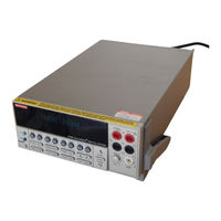
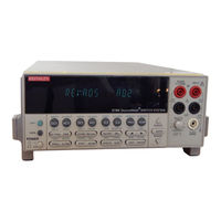
User Manuals: Keithley 2790 SourceMeter Switch System
Manuals and User Guides for Keithley 2790 SourceMeter Switch System. We have
2
Keithley 2790 SourceMeter Switch System manuals available for free PDF download: Reference Manual, User Manual
Keithley 2790 Reference Manual (568 pages)
Brand:
Keithley
| Category:
Switch
| Size: 3 MB
Table of Contents
Table of Contents
8
Getting Started
20
General Information
21
Contact Information
21
Safety Symbols and Terms
21
Inspection
21
Options and Accessories
22
Model 2790 Features
23
Plug-In Switching Modules
25
Pseudocards
26
Identifying Installed Switching Modules
26
Power Supply Restrictions with the 7753 Module
26
Front and Rear Panel Familiarization (QS1)
27
Front Panel Summary
27
Rear Panel Summary
31
Power-Up (QS2)
32
Line Power Connection
32
Line Frequency
33
Setting Line Voltage and Replacing Fuse
33
Power-Up Sequence
34
Keyclick
35
Display
35
Status and Error Messages
35
Remote Programming - Display
35
Defaults and User Setups
37
Saving and Restoring Setups
38
Remote Programming - Default and User Setups
42
Remote Programming Information
43
Quick Start Exercises (QS3)
43
Basic DMM Measurements - Front Panel Inputs
44
Closing and Opening Channels
46
Simple Scanning (7702)
51
Trigger and Return Readings - Remote Programming
54
Closing and Opening Switching Module Channels
58
Test System Safety Precautions
59
Close/Open Overview
59
Switching Module Installation and Connections
61
Module Installation
61
Connections
62
Pseudocards
63
Channel Assignments
63
System Channel Operation (7702 Only)
64
2-Wire Functions
64
4-Wire Functions (Paired Channels)
65
Controlling the System Channel
66
Multiple Channel Operation
70
Controlling Multiple Channels
71
Multiple Channel Operation Anomalies (7702 Only)
76
Dual Independent Multiplexers (7702 Only)
78
Identifying Installed Modules and Viewing Closed Channels
83
CARD Menu
83
Switching Module Queries (Remote Operation)
85
Relay Closure Count
86
Reading Relay Closure Count
87
Setting Count Update Interval
87
Models 7751, 7752, and 7753 Switching Modules
88
Switching Module Capabilities
88
Model 7702 Switching Module
90
Switching Module Capabilities
90
Schematic Diagram
91
Memory Patterns
93
Description
93
Recalling Memory Patterns from the Front Panel
93
Memory Pattern Commands
94
Memory Pattern Command Options
96
Memory Pattern Scanning
96
Memory Patterns Program Example
96
Basic DMM Operation
106
DMM Measurement Capabilities
107
High Energy Circuit Safety Precautions
108
Performance Considerations
109
Warm-Up
109
Autozero
109
LSYNC (Line Cycle Synchronization)
110
Remote Programming - Autozero and LSYNC
111
Channel Scan List Parameter
111
7702 Module Scanning
111
Memory Pattern Scanning
112
Voltage Measurements (DCV and ACV)
113
DCV Input Divider
113
Connections
113
Volts Measurement Procedure
116
Crest Factor
117
Low Level Considerations
117
Current Measurements (DCI and ACI)
118
Connections
119
Amps Measurement Procedure
120
AMPS Fuse Replacement (Front Panel AMPS Input)
121
Resistance Measurements (Ω2 and Ω4)
121
Connections
122
Standard Resistance Measurements
124
Offset-Compensated Ohms
125
Temperature Measurements
127
Thermistors
127
4-Wire Rtds
127
Connections
128
Temperature Measurement Configuration
129
Temperature Measurement Procedure
131
Frequency and Period Measurements
132
Trigger Level
132
Gate Time
132
Connections
133
Frequency and Period Measurement Procedure
134
Continuity Testing
135
Connections
135
Continuity Testing Procedure
136
Remote Programming for Basic Measurements
137
Basic Measurement Commands
137
Basic Measurement Programming Examples
143
Measurement Queries
144
Fetch
144
Read
145
Measure[:<Function>]
145
[:Sense[1]]:Data:fresh
146
[:Sense[1]]:Data[:Latest]
146
Examples
147
Range, Digits, Rate, Bandwidth, & Filter
148
Range
149
Measurement Ranges and Maximum Readings
149
Manual Ranging
150
Auto Ranging
150
Scanning (7702 Only)
150
Remote Programming - Range
151
Digits
153
Scanning (7702 Only)
153
Remote Programming - Digits
153
Rate and Bandwidth
155
Rate
155
Bandwidth
157
Scanning (7702 Only)
157
Remote Programming - Rate and Bandwidth
157
Filter
160
Filter Characteristics
160
Remote Programming - Filter
165
Relative, Math, Ratio, Channel Average, and Db Relative
168
Basic Operation
169
Remote Programming - Rel
171
Math
174
MX+B
175
M/X + B (Reciprocal)
176
Percent
178
Sxiohms
179
Sxvohms
180
Basic Operation
181
Remote Programming - Math
182
Ratio and Channel Average (7702 Only)
185
Basic Operation
186
Remote Programming - Ratio and Channel Average
188
Remote Programming - Db
190
Buffer
192
Buffer Overview
193
Front Panel Buffer
193
Auto Clear
193
Timestamps
195
Storing Readings
196
Recalling Readings
197
Buffer Statistics
198
Remote Programming - Buffer
199
Buffer Commands
199
Programming Example
205
Scanning
206
Scanning Fundamentals
207
7702 Module Scanning
207
7751/7752/7753 Module Scanning
215
Scan Configuration (7702 Only)
216
Scan Reset
218
Simple Scan
219
Advanced Scan
220
Setting Delay
223
Monitor Channel
223
Auto Channel Configuration
225
Saving Setup
225
Auto Scan
226
Scan Operation (7702 Only)
226
Basic Scan
226
Manual/External Trigger Scan
227
Monitor Scan (Analog Trigger)
229
Remote Programming - Scanning
231
7702 Module Scanning
231
7751/7752/7753 Module Scanning
232
Scanning Commands
234
Scanning Programming Example
238
Scanning Examples
238
External Trigger Scan
239
Monitor Scan
242
Triggering
246
Trigger Model
247
Idle
247
Control Source and Event Detection
248
Delay (Auto or Manual)
248
Device Action
250
Output Trigger
250
Reading Hold (Autosettle)
251
Hold Example
251
External Triggering
252
Digital I/O
253
External Trigger
253
Voltmeter Complete
254
External Triggering Example
255
External Triggering with BNC Connections
258
Remote Programming - Triggering
260
Trigger Model (Remote Operation)
260
Trigger Model Operation
262
Triggering Commands
263
Programming Example
264
Limits and Digital I/O
266
Limits
267
Front Panel Scanning (7702 Only)
269
Remote Scanning
269
Basic Limits Operation
269
Digital I/O
270
Digital Input (Trigger Link Input)
270
Digital Outputs
271
Setting Digital Output
276
Scanning
277
Remote Programing - Limits and Digital Output
278
Limits and Digital Output Commands
278
Limits and Digital Outputs Programming Example
280
Application - Sorting Resistors
281
Limits
281
Digital Outputs
283
Remote Operations
284
Operation Enhancements
285
Pseudocards
285
Autozero
285
Db Calculation
285
Separate Function Setups
285
DCV Input Divider
286
Multiple Channel Operation
286
GPIB Setup
286
GPIB Standards
286
Selecting GPIB and Setting Primary Address
287
GPIB Connections
287
General Bus Commands
290
REN (Remote Enable)
290
IFC (Interface Clear)
291
LLO (Local Lockout)
291
GTL (Go to Local)
291
DCL (Device Clear)
291
SDC (Selective Device Clear)
291
GET (Group Execute Trigger)
292
SPE, SPD (Serial Polling)
292
Front Panel GPIB Operation
292
Error and Status Messages
292
GPIB Status Indicators
292
LOCAL Key
293
Programming Syntax
293
Command Words
293
Query Commands
295
Case Sensitivity
296
Long-Form and Short-Form Versions
296
Short-Form Rules
296
Program Messages
297
Response Messages
299
Message Exchange Protocol
300
RS-232 Interface Operation
300
Sending and Receiving Data
300
Baud Rate
300
Signal Handshaking (Flow Control)
301
Terminator
302
Selecting and Configuring RS-232 Interface
302
RS-232 Connections
303
Error Messages
304
Status Structure
306
Overview
307
Status Byte and SRQ
307
Status Register Sets
307
Queues
307
Clearing Registers and Queues
309
Programming and Reading Registers
310
Programming Enable Registers
310
Reading Registers
311
Status Byte and Service Request (SRQ)
311
Status Byte Register
312
Service Request Enable Register
313
Serial Polling and SRQ
313
Status Byte and Service Request Commands
314
Serial Poll Programming Example
315
Status Register Sets
317
Register Bit Descriptions
317
Condition Registers
323
Event Registers
324
Event Enable Registers
325
Queues
326
Output Queue
326
Error Queue
326
Common Commands
328
SCPI Signal Oriented Measurement Commands
336
Configure:<Function> [<Rang>], [<Res>], [<Clist>]
339
Fetch
341
Read
342
Measure:<Function>? [<Rang>], [<Res>], [<Clist>]
343
Format and Miscellaneous System Commands
346
Format Commands
347
Format[:Data] <Type>[,<Length>]
347
Format:elements <Item List
351
Format:border <Name
352
Miscellaneous System Commands
353
System:preset
353
System:version
353
System:key <Nrf
353
System:beeper[:State] <B
354
SCPI Reference Tables
356
Reference Tables
357
Performance Verification
382
Introduction
383
Verification Test Requirements
383
Environmental Conditions
383
Warm-Up Period
384
Line Power
384
Recommended Test Equipment
385
Verification Limits
386
Example Reading Limit Calculation
386
Calculating Resistance Reading Limits
386
Restoring Factory Defaults
386
Performing the Verification Test Procedures
387
Verification Test Summary
387
Test Considerations
388
Model 2790 Verification
389
Verifying DC Voltage
389
Verifying AC Voltage
391
Verifying DC Current
393
Verifying AC Current
394
Verifying Resistance
395
Verifying Temperature
397
Verifying Frequency
398
Model 7702 Verification
399
Verifying DC Voltage
399
Verifying AC Voltage
401
Verifying DC Current
402
Verifying AC Current
404
Verifying Resistance
405
Verifying Temperature
407
Verifying Frequency
408
Verifying Ratio and Average
409
Model 7751, 7752, and 7753 Verification
409
Recommended Test Equipment
410
Verifying the Current Source
411
Verifying the Voltage Source (Model 7751 and 7753 Only)
412
Verifying the Current Measure Input (Model 7751/7753 Only)
413
Verifying Source-Current Resistance
414
Verifying Source-Voltage Resistance (Model 7751/7753 Only)
416
Calibration
420
Introduction
421
Environmental Conditions
421
Warm-Up Period
421
Line Power
421
Calibration Considerations
422
Calibration Code
423
Front Panel Calibration Code
423
Remote Calibration Code
423
Comprehensive Calibration
424
Calibration Cycle
424
Recommended Equipment
424
Aborting Calibration
425
Front Panel Calibration
425
Remote Calibration
433
Manufacturing Calibration
439
Firmware Revision Level
439
Recommended Test Equipment
440
Extender Board Preparation
440
Test Equipment Connections
440
Unlocking Manufacturing Calibration
440
Calibration for Firmware Revision A04 and Higher
441
Calibration for Firmware Revision A03 and Lower
443
Model 7751, 7752, and 7753 Calibration
445
Recommended Test Equipment
445
Model 7751/7752/7753 Calibration
446
Routine Maintenance
448
Introduction
449
Setting the Line Voltage and Replacing the Line Fuse
449
Replacing the AMPS Fuse
451
Replacing Model 7702 Plug-In Module Amps Fuses
452
Replacing Model 7751/7752/7753 Plug-In Module Fuses
453
Replacing Non-Volatile RAM Battery
455
Plug-In Module Relay Closure Count
456
Closure Count Commands
456
Reading Relay Closure Count
457
Resetting Relay Closure Count
457
Setting Count Update Interval
458
Front Panel Tests
458
KEY Test
458
DISP Test
459
(Models 2790, 7751, 7752, 7753, and 7702
460
Ohms Specification Calculations (7751/7752/7753
467
7751/7752/7753 I-Source
467
7751/7753 V-Source
468
Signal Processing Sequence
481
Basic Signal Processing
481
Signal Processing Using Instrument Features
482
Signal Processing Using Ratio or Ch Avg
485
Data Flow (Remote Operation
486
Sense and Sample Buffer
487
[Sens[1]]:Data[Latest]
488
[Sens[1]]:Data:fresh
488
Fetch
489
Read
489
Measure
489
Calc[1]:Data[Latest
489
Calc[1]:Data:fresh
489
Calc3:Lim1:Fail
490
Calc3:Lim2:Fail
490
Trace:data
490
Calc2:IMM
491
Calc2:Data
491
Continuous Measurement Mode
491
Scanning
492
Measurement Considerations
494
Thermoelectric Potentials
495
Thermoelectric Generation
496
Minimizing Thermal Emfs
497
Source Resistance Noise
498
Magnetic Fields
499
Radio Frequency Interference
499
Shielding
502
Meter Loading
503
Thermistor Equation
505
RTD Equation
507
Introduction
511
Bus Description
511
Bus Lines
513
Data Lines
513
Bus Management Lines
514
Handshake Lines
514
Bus Commands
515
Uniline Commands
516
Universal Multiline Commands
517
Addressed Multiline Commands
517
Address Commands
518
Unaddress Commands
518
Common Commands
518
SCPI Commands
518
Command Codes
520
Typical Command Sequences
521
IEEE Command Groups
522
Interface Function Codes
523
Introduction
527
Command Summary
527
Miscellaneous Calibration Commands
529
Code
529
Count
529
Init
530
Lock
530
Lock
531
Save
531
Date
532
Ndue
532
DC Calibration Commands
533
Step1
533
Step2
534
Step3
534
Step4
534
Step5
535
Step6
535
Step7
535
Step8
536
Step9
536
Step10
536
Step11
537
Step12
537
AC Calibration Commands
538
Ac:step<N
539
Manufacturing Calibration Commands
540
Ac:step<14|15
540
DC:step0
540
Model 7751, 7752, and 7753 Calibration Commands
541
Code
542
Count
542
Date
543
Init
543
Lock
544
Rcount
544
Current Source Calibration Commands
545
Data
545
Save
546
Remote Error Reporting
547
Error Summary
547
Error Queue
549
Status Byte EAV (Error Available) Bit
549
Generating an SRQ on Error
549
Detecting Calibration Step Completion
549
Using the *OPC? Query
549
Using the *OPC Command
550
Generating an SRQ on Calibration Complete
550
Calibration Program
551
Computer Hardware Requirements
551
Software Requirements
551
Calibration Equipment
551
General Program Instructions
552
Advertisement
Keithley 2790 User Manual (130 pages)
sourcemeter switch system
Brand:
Keithley
| Category:
Switch
| Size: 1 MB
Table of Contents
Table of Contents
6
Test System Overview
12
Introduction
13
Key Features
13
Technical Terms
14
Model 2790 Configurations
15
1 Test System Overview
16
Test System
16
Figure 1-1 System Connections
16
Inflator Tests
17
Shunt Bar Test
17
Figure 1-2 Shunt Bar Testing
18
Bridgewire Test
19
Figure 1-3 Bridgewire Testing
19
Insulation Resistance (HIPOT) Test (7751 and 7753 Only)
20
Keithley 7751, 7752, and 7753 Switching Modules
22
Card Configuration
23
2 Keithley 7751, 7752, and 7753 Switching Modules
24
Figure 2-1 Simplified Schematic of Keithley 7751, 7752, and 7753 Switching Modules
24
I-Source - Channels 21, 22, 24, and 27
25
V-Source and I/V Amplifier (7751/7753 Only) - Channels
25
Cable Discharge (7751/7753 Only) - Channel 20
25
Source Readback - Channels 13 and 25
26
Interlock - J106
26
General Purpose Terminal Blocks - J105, J107, and J108
26
Safety Warnings
27
Setting Source Output Levels
27
Figure 2-2 Setting I-Source and V-Source Output Levels
28
Remote Programming
29
Math
30
Front Panel Operation
32
Remote Programming
32
Table 2-2 Commands to Select Ohms Calculations
33
Opening and Closing Channels
34
Front Panel Operation
34
Remote Programming
35
Viewing Closed Channels
36
Open Interlock Errors
37
Cable Discharge Circuit (7751 and 7753)
38
Figure 2-6 Cable Discharge Circuit
39
Connection Log
40
Using Memory Patterns
41
Firmware Revision Level
41
Overview
41
Front Panel Operation
41
Memory Pattern Commands
42
Setting up and Executing Memory Patterns
42
Memory Pattern Command Options
43
Memory Pattern Scanning
43
Memory Pattern Log
44
Keithley 7702 Switching Module
46
Safety Precautions
47
Card Configuration
48
3 Keithley 7702 Switching Module
49
Figure 3-1 Simplified Schematic of Keithley 7702 Switching Module
49
Typical Connections
50
Figure 3-3 Ω4 and RTD TEMP Connections
51
Figure 3-4 Current Connections (DCI and ACI)
51
Connection Log
52
Table 3-1 Connection Log Model 7702
53
Opening and Closing 7702 Channels
54
Channel Assignments
54
Front Panel Operation
55
Figure 3-6 Andkeys
55
Figure 3-7 CLOSE Key
55
Remote Programming
56
Figure 3-8 OPEN Key
56
Viewing Closed Channels
57
Using 7751/7753 V-Source with 7702 Module
58
Switching Module Wiring and Installation
60
Connections and Wiring
61
Screw Terminals
61
Cabling Requirements
62
Wiring Procedure
63
Figure 4-2 Model 7751/7752/7753 Screw Terminal Channel Designations
64
Figure 4-3 Model 7702 Screw Terminal Channel Designations
65
Figure 4-4 Wire Dressing (7751/7752/7753)
66
Zippertubing® Shield
67
Guarding
68
Switching Module Installation
69
Module Slot Considerations
69
Power Supply Restrictions with the 7753 Module
69
Installation Procedure
69
Inflator Testing
70
Introduction
71
Test Procedures
71
Closed Channels for Test Circuits
72
5 Inflator Testing
72
Test System
72
Figure 5-1 System Connections
72
GPIB (PC Only)
73
Interface (PLC or PC)
73
Test Signal Connections
74
Figure 5-3 Test Connections – Shunt Bar, HIPOT, and Bridgewire Testing – Single Stage Inflator
75
Figure 5-4 Test Connections – Shunt Bar and Bridgewire Bar Testing – Dual Stage Inflator
76
Figure 5-5 Test Connections – Shunt Bar, HIPOT, and Bridgewire Testing – Dual Stage Inflator
77
Interlock
78
Shunt Bar Test
79
Test Circuit
80
Figure 5-7 Test Circuit - Shunt Bar
80
Test Procedure
81
I-Source Readback
81
Table 5-1 Test Procedure – Shunt Bar
82
Bridgewire Tests
83
Test Circuit
83
Test Procedure
84
I-Source Readback
85
Insulation Resistance (HIPOT) Tests (7751/7753 Only)
86
Contact Checks
87
Figure 5-10 Test Circuits - Contact Check - Dual Stage Inflator
88
Figure 5-9 Test Circuits - Contact Check - Single Stage Inflator
88
Table 5-3 Test Procedure – Contact Checks for Single Stage Inflator
89
Table 5-4 Test Procedure – Contact Checks for Dual Stage Inflator
90
V-Source Readback
91
Figure 5-11 V-Source Readback Circuit
91
Cable Discharge
92
HIPOT Test
93
Figure 5-12 Test Circuit - HIPOT
94
Test Procedure - HIPOT
95
I-Source Readback
97
Figure 5-13 I-Source Readback Circuit
98
Memory Patterns Test
99
Test Circuit
99
Figure 5-14 Test Circuits - Memory Patterns - Dual Stage Inflator Contact Test
99
Test Procedure
100
Table 5-8 Command Sequence for Memory Patterns Test Example Using Individual Memory Pattern Recall
102
Model 2790 DMM Ohms Functions
104
Introduction
105
Low Ohms Measurements
105
Fuse Resistance Considerations
105
High Ohms Measurements
106
4-Wire Ohms
106
Offset Compensated Ohms
108
Keithley 7702 Module
109
Keithley 7751, 7752, and 7753 Modules
111
Figure 6-6 Using Model 2790 2-Wire Ohms with 7751/7752/7753 Module (High Ohms Measurements)
112
Specifications
114
(Models 2790, 7751, 7752, 7753, and 7702
114
Ohms Specification Calculations (7751/7752/7753
121
7751/7752/7753 I-Source
121
7751/7753 V-Source
122
Advertisement
Related Products
Keithley 2750
Keithley 2308-3Y-EW
Keithley 2701
Keithley 2700
Keithley Integra 27 Series
Keithley 2502
Keithley Interactive SourceMeter 2450
Keithley 2651A
Keithley 244
Keithley 2230-60-3
Keithley Categories
Measuring Instruments
Multimeter
Test Equipment
Power Supply
Switch
More Keithley Manuals
Login
Sign In
OR
Sign in with Facebook
Sign in with Google
Upload manual
Upload from disk
Upload from URL