Table of Contents
Advertisement
Quick Links
Advertisement
Chapters
Table of Contents

Related Manuals for Keithley 7002


Summary of Contents for Keithley 7002
-
Page 1: Instruction Manual
® Advanced Test Equipment Rentals www.atecorp.com 800-404-ATEC (2832) Model 7002 Switch System Instruction Manual A G R E A T E R M E A S U R E O F C O N F I D E N C E... - Page 2 WARRANTY Keithley Instruments, Inc. warrants this product to be free from defects in material and workmanship for a period of 1 year from date of shipment. Keithley Instruments, Inc. warrants the following items for 90 days from the date of shipment: probes, cables, rechargeable batteries, diskettes, and documentation.
- Page 3 Model 7002 Switch System Instruction Manual ©1993, Keithley Instruments, Inc. All rights reserved. Cleveland, Ohio, U.S.A. January 2002, Fourth Printing Document Number: 7002-901-01 Rev. D...
- Page 4 Revision C (Document Number 7002-901-01) ................September 1998 Revision D (Document Number 7002-901-01) ................January 2002 All Keithley product names are trademarks or registered trademarks of Keithley Instruments, Inc. Other brand and product names are trademarks or registered trademarks of their respective holders.
-
Page 5: Safety Precautions
Do not touch any object that could provide a current path to the com- Keithley products are designed for use with electrical signals that mon side of the circuit under test or power line (earth) ground. Always... - Page 6 Safe operation requires the use of a components in mains circuits, including the power transformer, test lid interlock. leads, and input jacks, must be purchased from Keithley Instru- ments. Standard fuses, with applicable national safety approvals, If a screw is present, connect it to safety earth ground using the may be used if the rating and type are the same.
- Page 7 SWITCH SETTLING TIME: Automatically selected by the LIGHT PEN OPTION: Provides interactive programming Break-Before-Make OFF 300 mainframe. For different switchcards, 7002 will be set to of channels, cross points, scan lists, and memory. the slowest relay settling time. Additional time from 0 to ON 270 REAR PANEL CONNECTORS: 99999.999 seconds can be added in 1ms increments.
-
Page 8: Table Of Contents
Table of Contents General Information Introduction ..............................1-1 Features ................................1-1 Warranty information ............................1-1 Manual addenda .............................. 1-2 Safety symbols and terms ..........................1-2 Specifications ..............................1-2 Inspection ................................ 1-2 Optional accessories ............................1-2 Card Installation Introduction ..............................2-1 Model 701X series card installation ........................ - Page 9 3.8.2 Installing switching cards ........................3-13 3.8.3 Card type ............................. 3-13 Front panel operation summary ........................3-14 3.9.1 Create channel list and/or scan list ...................... 3-14 3.9.2 Close and Open channels ........................3-15 3.9.3 Scan channels ............................3-15 3.10 Introduction to IEEE-488.2 and SCPI ......................3-16 3.10.1 Bus connections ...........................
- Page 10 4.10.3 Scanning examples ..........................4-26 4.11 Channel patterns (STORE and RECALL) ....................4-27 4.11.1 Storing channel patterns (STORE) ...................... 4-28 4.11.2 Recalling channel patterns (RECALL) ....................4-29 4.12 MENU ................................4-29 4.12.1 SAVESETUP ............................4-31 4.12.2 GPIB ..............................4-33 4.12.3 DIGITAL-I/O ............................
- Page 11 Status structure ..............................5-6 5.6.1 Standard event status ..........................5-8 5.6.2 Operation event status ........................... 5-9 5.6.3 Arm event status ..........................5-12 5.6.4 Sequence event status .......................... 5-14 5.6.5 Trigger event status ..........................5-16 5.6.6 Questionable event status ........................5-19 5.6.7 Queues ..............................
- Page 12 5.13.4 :FCHannels <list> ..........................5-85 5.13.5 :INTerlock:LIST Commands ....................... 5-86 5.13.6 :BBMake <b> ........................... 5-88 5.13.7 :SCHannel <b> ..........................5-88 5.13.8 :CPAirX <b> where; X=[1] to 5 ....................... 5-89 5.13.9 :CTYPe <name> ..........................5-91 5.13.10 :POLE <NRf> ............................5-92 5.13.11 :STIMe <n>...
- Page 13 Relay control circuitry ............................ 6-5 6.4.1 Backplane interface ..........................6-5 6.4.2 Switch card interface ..........................6-6 6.4.3 ID data circuits ............................6-6 6.4.4 Relay control ............................6-8 6.4.5 Power-on safeguard ..........................6-8 VFD display board circuitry ........................... 6-8 LED display board circuitry ........................... 6-9 External control signals ..........................
- Page 14 7.7.8 Display test — char set ........................7-13 Test descriptions and notes ........................... 7-13 7.8.1 Initial power-up test ..........................7-13 7.8.2 Non-volatile memory tests ........................7-13 7.8.3 Built-in-tests ............................7-13 Troubleshooting ............................7-16 7.9.1 Digital board ............................7-16 7.9.2 Display boards ............................. 7-16 7.9.3 Power supply ............................
- Page 15 List of Illustrations Card Installation Figure 2-1 Card installation ........................... 2-3 Getting Started Figure 3-1 Model 7002 front panel ........................3-2 Figure 3-2 Model 7002 rear panel ......................... 3-3 Figure 3-3 Optional light pen ..........................3-4 Figure 3-4 Relay status display mode ........................3-4 Figure 3-5 List display modes ..........................
- Page 16 IEEE-488 connections ......................... 5-2 Figure 5-3 IEEE-488 connector location ......................5-3 Figure 5-4 Contact configuration .......................... 5-3 Figure 5-5 Model 7002 status register structure ....................5-7 Figure 5-6 Standard event status ........................... 5-8 Figure 5-7 Operation event status ........................5-10 Figure 5-8 Arm event status ..........................
- Page 17 Theory of Operation Figure 6-1 Model 7002 system block diagram ...................... 6-2 Figure 6-2 Block diagram — digital circuitry and memory .................. 6-4 Figure 6-3 Backplane interface simplified schematic ................... 6-6 Figure 6-4 Block diagram — backplane interface (one slot) ................6-7 Figure 6-5 Timing diagram, IDCLK and IDDATA ....................
- Page 18 List of Tables Getting Started Table 3-1 Abbreviated common command summary ..................3-17 Table 3-2 Abbreviated SCPI command summary ..................... 3-18 Front Panel Operation Table 4-1 Error and status messages ........................4-3 Table 4-2 Significance of channel LEDs ......................4-12 Table 4-3 MENU structure ..........................
- Page 19 Table E-1 IEEE-488 documentation requirements ....................E-1 SCPI Conformance Information Table F-1 Syntax of SCPI confirmed commands implemented by Model 7002 ..........F-2 Table F-2 Syntax of non-SCPI commands implemented by Model 7002 ............F-5 SCPI Command Subsystems Table H-1 DISPlay command summary ......................
-
Page 20: General Information
Model 701X series 7002 Switch System. cards installed in the other slots. • Close/Open or Scan The Model 7002 can simply Features close and/or open one or more channels, or scan Warranty Information through a specified list of channels. -
Page 21: Manual Addenda
Use standard safety pre- cautions to avoid personal contact with these voltages. Model 7002-RMK-2 Slide Rack Mount Kit: Similar to the Model 7002-RMK-1 except the unit can slide in and out of the rack. The WARNING heading used in this manual explains dan- gers that might result in personal injury or death. -
Page 22: Card Installation
Introduction WARNING Turn off power from all instrumentation The Model 7002 is designed to be used with the Model 701X (including the Model 7002 mainframe) series switch cards (i.e. Model 7011, 7012, 7013, and 7014), and disconnect their line cords. Make... -
Page 23: Non-701X Series Cards
2. Facing the rear panel of the Model 7002, select the slot nal circuitry is wired to the card (as ex- (CARD 1 through CARD 10) that you wish to install the plained in the instruction manual for the card in. -
Page 24: Figure 2-1 Card Installation
To remove the card, first unlock it by pulling the ejector arms NOTE outward, then pull the card out of the mainframe. Remember The Model 7002 cannot automatically to handle the card by the edges to avoid contamination that identify non-701X cards. After the main- could degrade performance. -
Page 25: Getting Started
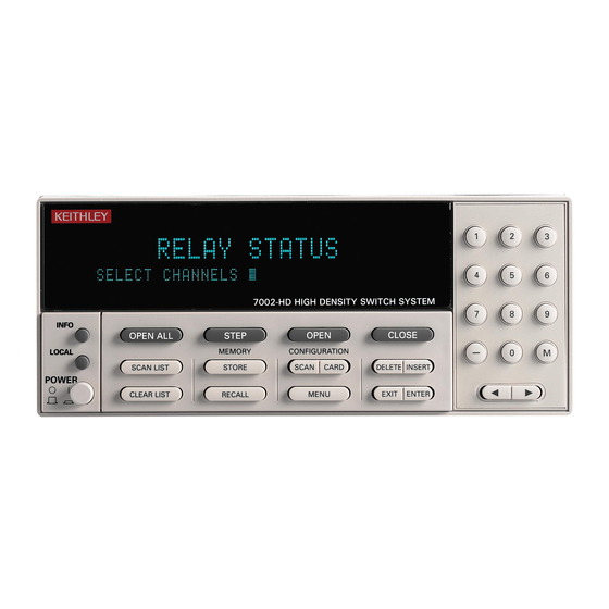
3.2.1 Front panel Display modes: Covers the two basic display modes The front panel of the Model 7002 is shown in Figure 3-1. and explains how to toggle from one display mode to This figure includes important abbreviated information that the other. -
Page 26: Figure 3-1 Model 7002 Front Panel
Insert an entry at selected Move cursor to end of STEP location in Channel List or Scan selected list. Takes 7002 out of idle state and can be List. Same as - key used to step through the Scan List. SHOW LIST... -
Page 27: Light Pen Option
Use standard IEEE-488 cables. units that do not have front panel controls. Figure 3-2 Model 7002 rear panel Display modes Light pen option Point and click programming using the light pen provides an There are two basic display modes; the relay status display mode and the list display mode. -
Page 28: Figure 3-3 Optional Light Pen
Getting Started CL OS E 9 10 SL OT 7 CO LU MN ST EP SL OT 1 CO LU MN 9 10 RO W SL OT 6 SC AN LIS CO LU MN RO W CO LU MN IN SE RT DE LE TE RO W 9 10... -
Page 29: Changing The Display Mode (Keypad Method)
Getting Started Channel assignments COLUMN SLOT 1 9 10 Channel assignment format depends on the type of card in- stalled in the mainframe. A matrix card uses a three integer format to specify slot, row, and column, while a non-matrix type card uses a two integer format to specify slot and chan- nel. -
Page 30: Figure 3-8 Channel Assignment Formats
Getting Started For a matrix card, each channel LED in the array corre- For a non-matrix type card, each channel LED in the array sponds to a row/column crosspoint. The channel assign- corresponds to one of up to 40 channels. The channel assign- ments for matrix cards are shown in Figure 3-8A. -
Page 31: Overview Of Scan Process
Getting Started Overview of scan process When the Model 7002 is taken out of the idle state by press- ing STEP (or sending the :INIT or :INIT:CONT ON com- The following overview is intended to acquaint you with the mand over the IEEE-488 bus), the ARM indicator turns on basic scan fundamentals without the details of enhanced ca- and operation proceeds into the arm layer. -
Page 32: Operation Demo
40-channel multiplexer. 5. Press EXIT twice to exit from the MAIN MENU. Step 1 of the following procedure will RESET the Model 7002 to a default configuration that is required for the dem-... -
Page 33: Close And Open Channels
Getting Started 3.7.2 Close and open channels 3. Individual Channel Entry – Enter channels 2 and 4 into the channel list: The following procedures assume that the initial configura- tion procedure in paragraph 3.7.1 has been performed. This Keypad method initialization will assign the 40-channel multiplexer simula- tor to slot 9. - Page 34 Getting Started Light pen method b. Press OPEN (or OPEN ALL) to open the channels specified in the channel list. Note that OPEN ALL a. Click channel 6 of slot 9. also opens channels not specified in the list. SELECT CHANNELS 9!2, 9!4, 9!6, Light pen method b.
-
Page 35: Scan Channels
(Channel 1). Light pen method 1. Press STEP to take the Model 7002 out of the idle state. a. Click the LED that corresponds to channel 1 of slot The ARM indicator will turn on. - Page 36 Getting Started 5. When finished, press OPEN ALL to abort the scan and 12. Press EXIT twice to back out of the menu structure. open all channels. The instrument goes into the idle state 13. To start the scan, simply press STEP. The instrument (ARM indicator turns off).
-
Page 37: Switching Card Considerations
Instrument operation can be performed without any switch- SET CARD TYPE 7012 ing cards installed in the Model 7002 by using the switching SLOT-#1 #2 #3 #4 #5 card simulators. By selecting the appropriate switching card simulator, the Model 7002 will operate as if a 40-channel In the above example, if #3 flashes, it indicates that the... -
Page 38: Front Panel Operation Summary
S!C (Non-matrix card) WARNING where; S = slot S = slot Before turning the Model 7002 on, make R = row C = channel sure it is connected to a grounded power C = column receptacle using the supplied power cord or equivalent. -
Page 39: Close And Open Channels
Getting Started 3.9.2 Close and Open channels Step 1. Make sure the RELAY STATUS display mode is selected Perform the following steps to control (close/open) the chan- If the instrument is not in the RELAY STATUS display nels defined in the channel list. mode, perform the following to select it: Keypad Method Step 1. -
Page 40: Introduction To Ieee-488.2 And Scpi
Getting Started 5. Use the keypad to key in the desired scan count and 3. Place the cursor on CHANNEL SPACING and press press ENTER. ENTER to select the SELECT CHAN SPACING menu. 6. Use EXIT to back out of the menu structure. 4. -
Page 41: Bus Connections
An instrument that uses the IEEE-488.2 standard and SCPI does not have special hardware requirements. The IEEE-488 The primary address of the Model 7002 must agree with the interface that you used with the old standard will work with primary address you intend to specify in the controller’s pro- the new standard. -
Page 42: Abbreviated Scpi Command Summary
:TRIGger:SOURce? query command is used to request the commands necessary to perform some basic operations. currently selected control source. After the query command is sent and the Model 7002 is addressed to talk, a message identifying the selected control source will be sent to the computer. -
Page 43: Abbreviated Syntax Rules
:CLOSe:STATe? Queries the channels that are closed. (:OPEN) and the parameter (ALL). Whenever a query command is sent, the Model 7002 must be The general form for Common Commands is shown in Table addressed to talk in order to send the response message to the 3-1. -
Page 44: Programming Examples
Take 7002 out of idle state. The following programming examples are written in Hewlett-Packard BASIC 4.0 programming language. The programs assume that the Model 7002 is set to primary ad- When the above program is run, the scan will arm (ARM in- dress 7. - Page 45 Set scan layer timer for 10 second interval. 40 END Line 25 Program channel control source for timer. Line 26 Set channel layer timer for 0.5 second interval. Line 30 Take 7002 out of idle state to start the scan. 3-21...
- Page 46 Getting Started 3-22...
-
Page 47: Front Panel Operation
Channel list and Scan list: Explains how to create a channel list (for open/close operations) and a scan list The Model 7002 can be operated from line voltages from (for scanning operations). 100-240VAC at line frequencies of 50 or 60Hz. -
Page 48: Line Power Connections
Front panel displays 4.2.3 Power-up sequence The Model 7002 uses two displays. The vacuum fluorescent On power-up, the Model 7002 will go through the following display (VFD) provides alphanumeric information while the sequence: LED array display provides status information for each channel. -
Page 49: Table 4-1 Error And Status Messages
“Invalid Character” (EE) -102 “Syntax Error” (EE) with operation of the light pen option. Error and status mes- sages for the Model 7002 are summarized in Table 4-1. Light -103 “Invalid Separator” (EE) pen messages are covered in paragraph 4.5.3. -
Page 50: Led Display
Register allows you to control which conditions will gener- Code ate an SRQ (see Section 5). number Description REM — Turns on to indicate that the Model 7002 is in re- -168 “Block data not allowed” (EE) mote when used over the IEEE-488 bus. The Model 7002 can -170 “Expression error”... -
Page 51: Analog Backplane
Figure 4-4 provides more detail by showing how each slot is Analog backplane connected to the backplane. The Model 7002 has a three-pole (High, Low and Guard) an- alog backplane that allows the rows (or banks) of a Model NOTE... -
Page 52: Figure 4-4 Analog Backplane (Detail For Each Slot)
Matrix Row (1 of 4) H = High Slot L = Low (1 of 10) G = Guard 7002 Analog Backplane 7012 Matrix Card Figure 4-4 Analog backplane (detail for each slot) Figure 4-5 Matrix row connections to analog backplane... -
Page 53: Light Pen Option
Not all Model 701X series cards can be connected to the an- pen. An LED that is clicked blinks for a couple of seconds alog backplane of the Model 7002. The Model 7013 relay and then assumes the appropriate state. Note that the associ- card is made up of 20 individual IN/OUT relay channels. -
Page 54: Light Pen Messages
BACKSPACE deletes that channel entry. This is analogous to pressing the key and then the There are two basic display modes for the Model 7002: DELETE key. Relay status display mode — Use this display mode when opening/closing or scanning channels. -
Page 55: List Display Modes
VFD which also includes the currently selected list. The following table summarizes the various display messages When programming the Model 7002, the and LED annunciators for the relay status display mode: slot number must be included with the ba- sic channel designation. -
Page 56: Changing The Display Mode
The significance of each channel LED while in a list display mode is summarized in Table 4-2. NOTE When programming the Model 7002, the A channel LED that is brightly lit indicates that it is included slot number must be included with the ba- in the selected list. -
Page 57: Led Graticule Control
Incorrect software revision 4.6.4 LED graticule control If this error should occur, contact Keithley LED Graticule control allows you to increase contrast be- to resolve the firmware incompatibility. tween on and off LEDs by eliminating the dimly lit state for LEDs. -
Page 58: Channel Assignments
4-7A and Figure 4-9A. When programming the Model (row/column) provides the CHANNEL assignment for the 7002, you need to designate the slot in which the card is in- mainframe. Slot, row, and column are separated by exclama- stalled. Thus, combining the slot number with the card chan- tion points (!). -
Page 59: Figure 4-10 Channel Assignments (Non-Matrix Type Cards)
Front Panel Operation Slot 1 1!10 1!15 1!16 1!17 1!18 1!19 1!20 1!11 1!12 1!13 1!14 1!21 1!22 1!23 1!24 1!25 1!26 1!27 1!28 1!29 1!30 1!31 1!32 1!33 1!34 1!35 1!36 1!37 1!38 1!39 1!40 Slot 2 2!10 2!11 2!12 2!13 2!14... -
Page 60: Figure 4-11 Channel Assignments (Matrix Cards)
Front Panel Operation Column Slot 1 1!1!1 1!1!2 1!1!3 1!1!4 1!1!5 1!1!6 1!1!7 1!1!8 1!1!9 1!1!10 1!2!1 1!2!2 1!2!3 1!2!4 1!2!5 1!2!6 1!2!7 1!2!8 1!2!9 1!2!10 1!3!7 1!3!8 1!3!9 1!3!10 1!3!1 1!3!2 1!3!3 1!3!4 1!3!5 1!3!6 1!4!1 1!4!2 1!4!3 1!4!4 1!4!5 1!4!6 1!4!7... -
Page 61: Channel List And Scan List
1 to 4-pole operation makes channel 1!21 unavailable and clears the entire Scan List. The Model 7002 can perform two basic operations; it can 4. Assume Channel Pattern M1 is included in the Scan List close and open a list of channels, and it can scan through a and M1 includes channel 1!1 as a closed channel. -
Page 62: Keypad Entry Method
SCAN CHANNELS 2!3!6 NOTE Step 1: Make sure appropriate list is selected. The Model 7002 can store up to 500 chan- Open/close operations use the channel list, and scan opera- nel patterns in memory locations M1 tions use the scan list. The SCAN LIST key toggles between through M500. - Page 63 Front Panel Operation 1. Changing a channel Perform the following steps to Step 3. Enter channel separator or terminator. change a channel: Channel separators are required for multiple channel entries, a. Use the cursor keys to place the cursor at the begin- and a terminator should be used after the last entered chan- ning of the channel entry to be changed.
-
Page 64: Light Pen Entry Method
Front Panel Operation 4.8.2 Light pen entry method range, the range entry will be cancelled and the last clicked channel will be added to the list. Perform the following steps to create a channel list or scan list using the optional light pen: NOTE Channel patterns from memory must be entered using the front panel keys. -
Page 65: Closing And Opening Channels
Note that a channel pattern cannot be entered into the list us- ing the light pen. One of the basic operations of the Model 7002 is to close (or open) one or more channels specified by the user. All the specified channels will either close or open at the same time. -
Page 66: Scanning Channels
ERROR: ID CODE = +350 cannot perform a scan. Too many channels closed From the front panel, the Model 7002 is taken out of the idle Summary of Close/Open keys and LEDs: state by pressing the STEP key. When not in the idle state (ARM indicator on) the scanning function is considered to CLOSE —... -
Page 67: Figure 4-12 Trigger Model (Front Panel Scan Process)
Front Panel Operation OPEN ALL Idle Idle STEP Another Arm Count Arm Trigger Control = Source (Source Bypass Enabled*) Output Trigger Arm Event Arm Layer Spacing Detection Manual Immediate Source GPIB Bypass External Enabled Triglink Hold Scan Trigger Control = Source Another Number of Scans (Source Bypass Enabled*) - Page 68 After all other trigger model operations are completed, the graph 4.14.3). Model 7002 can be returned to the arm layer by program- ming the instrument for additional arms. Arm Count can be In general, the instrument requires an arm event to allow op- set to infinity or to a finite value (1 to 9999).
-
Page 69: Scan Procedure
OPEN ALL (or clicking the OPEN ALL LED). This will stop any scan that is currently in process, open all channels, and place the Model 7002 in The Source Bypass (if enabled) will reset (be in effect) after the idle state. - Page 70 GPIB With this selection, bus triggers (GET or *TRG) control channel spacing. Each bus trigger re- SCAN CHANNELS 1!1, 4!1-4!10, M1, ceived by the Model 7002 will select the next chan- nel of the scan. The above scan list includes channel 1 of slot 1, and channels d.
- Page 71 IMMEDIATE With this selection, events are not *TRG) control scan spacing. A bus trigger received used to control arm spacing. Operation will proceed by the Model 7002 will allow operation to proceed immediately to the scan layer. to the channel layer.
-
Page 72: Scanning Examples
Step 7. Start the scan Model 7002 in the idle state. NOTE 2. Press STEP to take the 7002 out of the idle state (ARM indicator turns on). Make sure the relay status display mode is selected in order to monitor the real-time 3. -
Page 73: Channel Patterns (Store And Recall)
9. The next channel spacing event will scan the second place the Model 7002 in the scan idle state. channel and disarm (idle) the scanner. STEP Use to take the Model 7002 out of the idle state; and also, use to manually step through a scan. Example 4: ARM SPACING = MANUAL, GPIB, EXTERNAL or TRIGLINK 4.11 Channel patterns (STORE and RECALL) -
Page 74: Storing Channel Patterns (Store)
Front Panel Operation 4.11.1 Storing channel patterns (STORE) 3. Two or more closed channels in the Channel Pattern be- come interlocked. Channels become interlocked by There are two methods to store a channel pattern. One meth- specifying them in the Interlock lists. od is to actually close and open the desired channels and then save that pattern into memory. -
Page 75: Recalling Channel Patterns (Recall)
SELECT CHANNELS 1!1, 1!4, M10, RECALL. The open/close channel pattern will be reinstated by the Model 7002. The other way is to specify the memory location (i.e. M1) of the channel pattern in the channel list When CLOSE is pressed with the above channel list dis- and/or scan list. -
Page 76: Table 4-3 Menu Structure
Description SAVESETUP Setup Menu: SAVE Save setup at a memory location (up to 10). RESTORE Return 7002 to setup stored at a memory location. PWRON Power-on Menu: FACTORY DEFAULT Power-on to factory default setup conditions. USER SETUP Power-on to setup stored at a memory location. -
Page 77: Savesetup
Front Panel Operation 8. The INFO key can be used anywhere in the menu struc- 2. To save the current setup to a different memory location, ture to display helpful information messages concerning key in a value (0 to 9) and press ENTER. The instrument operation. -
Page 78: Table 4-4 Default Conditions
Front Panel Operation 1. To power-on to the setup conditions stored at the dis- Press ENTER to confirm or EXIT to abort. Pressing ENTER played memory location, press ENTER. The instrument will display the following message: will return to the SETUP MENU. RESET COMPLETE 2. -
Page 79: Gpib
The DIGITAL-I/O menu is used to configure the Model but it can be changed to any value from 0 to 30. To select AD- 7002’s digital I/O port (refer to paragraph 4.15). Perform the DRESS, place the cursor on ADDRESS and press ENTER. -
Page 80: Test
The TEST menu is to be used as a diagnostic tool to isolate SELECT OUTPUT LINE problems with the Model 7002. Refer to Section 7 Mainte- TTL1 TTL2 TTL3 TTL4 nance for information on using these test procedures. -
Page 81: General
The GENERAL MENU is used for the following operations: are performed. Place the cursor on STATUS-MESSAGES and press ENTER. The following message will be displayed: • Read the serial # of the Model 7002. STATUS MESSAGES • Read the SCPI version control number. - Page 82 CURRENT LIST selects the list display mode. Incorrect software revision 2. Place the cursor on the appropriate selection and press If this error should occur, contact Keithley to resolve the ENTER. The display returns to the LED DISPLAY firmware incompatibility.
-
Page 83: Card Configuration
1. The CARD CONFIG MENU is displayed by pressing the CARD CONFIGURATION key. The CARD CON- The TYPE menu selection displays an assignment message FIG MENU selections are shown as follows: for each slot. In general, the Model 7002 mainframe detects 4-37... -
Page 84: Table 4-6 Type Assignments
Front Panel Operation Table 4-6 (continued) (on power-up) Model 701X series cards that are installed. All TYPE assignments other type cards are not detected and thus, the slot must be assigned the appropriate model number by the user. This user Assignment message Interpretation* assigned model number is “remembered”... -
Page 85: Of-Poles
Front Panel Operation The message indicates that slot 5 is assigned as an more of those unavailable channels were included in the empty slot. Scan List and/or in a Channel Pattern, then the entire Scan List and/or the affected Channel Pattern will be lost b. -
Page 86: Delay
SET CARD PAIR 1&6 This menu selection is used to identify if there are any I/O OFF ON cards installed in the Model 7002. The cursor position indicates the state (on or off) of CARD PAIR for the two channels. -
Page 87: Scan Configuration
Front Panel Operation 4.14 Scan configuration 4. A displayed arrow ( ) indicates that there is more information or additional menu items to select Various operations to configure a scan are performed from from. When “ ” is displayed, use the cursor key to the CONFIGURE SCAN menu. -
Page 88: Table 4-7 Configure Scan Menu Structure
Front Panel Operation Table 4-7 CONFIGURE SCAN menu structure Menu item Description CHAN-CONTROL Configure Channel Layer: CHANNEL-SPACING Select channel spacing: TIMER Use a timer to select each channel in the scan. EXTERNAL Use an external trigger to select each channel. GPIB Use a bus trigger to select each channel. -
Page 89: Chan-Control
Each trigger stimulus played, select this menu item by placing the cursor on applied to the Model 7002 will open the current channel and CHANNEL-SPACING and pressing ENTER. The following close the next channel of the scan. The external trigger is ap- menu will be displayed: plied to the rear panel “EXTERNAL TRIGGER”... - Page 90 2. To select a trigger input line for the Model 7002, place next channel will close. the cursor on the desired line number and press ENTER.
- Page 91 (count) of channels to scan. The user programmed 2. To select a trigger line for the Model 7002, place the cur- count can be smaller, equal to, or larger than the number of sor on the desired line number and press ENTER. The channels in the scan list.
-
Page 92: Scan Control
NOTE pletion of a scan will start the next scan (assuming the Model When finished with the channel layer, use 7002 is programmed for another scan; see NUMBER OF EXIT to back out of the MENU structure. SCANS). Perform the following steps to use the timer: 4.14.2 SCAN CONTROL... - Page 93 Triglink — With this selection, scan spacing is controlled by 7002 will pass operation into the channel layer. The external the Trigger Link of the Model 7002. Trigger Link is an en- trigger is applied to the rear panel “EXTERNAL TRIGGER”...
-
Page 94: Arm Control
Front Panel Operation To select a trigger output line for the Model 7002, place the The above scan count indicates that the Model 7002 will cursor on a different line number and press ENTER. Note perform one scan. A value of “0000” indicates that the that you cannot use the same trigger line for both input and scan count is set to infinite. - Page 95 Triglink — With this selection, arm spacing is controlled by press ENTER. The instrument will return to the SETUP the Trigger Link of the Model 7002. Trigger Link is an en- ARM CONTROL menu. hanced trigger system that uses up to six lines to direct trig- ger pulses to and from other instruments.
- Page 96 #1 #2 #3 #4 #5 #6 mines the number of times operation returns to the arm layer. You can program the Model 7002 to arm up to 9999 times. Perform the following steps to enter the arm count: The position of the cursor indicates the currently selected in- put line.
-
Page 97: Channel Restrictions
Front Panel Operation 4.14.4 Channel restrictions Operating notes: The Model 7002 can be programmed for the following chan- 1. With Single Channel enabled and more than one chan- nel restrictions: nel assigned to the channel list, only the lowest num- bered channel in the lowest numbered slot will close •... - Page 98 4.8 and 4.11 for more information. INTERLOCK #1 LIST-A SELECT CHANNELS INTERLOCK — The Model 7002 has five channel inter- The above message shows an empty list. Unwanted locks. An interlock is a safety feature that prevents inter- channels can be cleared by pressing CLEAR LIST.
-
Page 99: Digital I/O Port
Front Panel Operation 3. Interlocked channels can be scanned as long as only one The Model 7002’s Digital I/O port can be used to control ex- channel is closed at a time. However, if a scan is per- ternal circuitry. The port provides four output lines and one formed while a channel is left closed, any channels in input line. -
Page 100: Controlling Digital Circuitry
Do not apply more than 100mA maxi- mum current or exceed +30V maximum voltage on pin 4 of J1006 (the digital I/O Early versions of the Model 7002 have an additional 10kΩ port). Applying current or voltage ex- resistor connected between the collector and the internal ceeding these limits may damage the in- built-in test circuitry. - Page 101 TTL, or CMOS inputs: A +5V output is available at pin 2 of the digital I/O connector (J1006). An internal 22Ω resistor is in series with the connec- 1. Connect the Model 7002 digital outputs to the logic in- tor pin. puts.
-
Page 102: Digital Input Channel
The Model 7002 has BNC connectors on the rear panel (see Figure 4-16) associated with external triggering. The EX- The Model 7002 has one digital input channel that is used to TERNAL TRIGGER input jack allows the Model 7002 to be read a TTL input level. -
Page 103: External Trigger
In general, external triggers can be used as events to control cludes the internally set relay settle time and the user scan operation. In order for the Model 7002 to respond to ex- programmed DELAY period; see paragraph 4.13.4). An out-... -
Page 104: External Triggering Example
7002 is connected to External Trigger Input of the Model then measure the DUT connected to that channel with a 196, and External Trigger (input) of the Model 7002 is con- DMM such as the Keithley Model 196. Such a test system is nected to Voltmeter Complete Output of the Model 196. -
Page 105: Trigger Link
DUT #2. When the measurement is completed, a ate layers of the scan must be properly programmed. For ex- trigger is sent to the Model 7002 to close the next channel. ample, if you want Trigger Link input triggers to control the... -
Page 106: Asynchronous Operation
The Trigger Link connections for this test system are shown lines, but they cannot use the same line. For example, if you in Figure 4-23. Trigger Link of the Model 7002 is connected select line #1 for input triggers, then output triggers must use to Trigger Link of the meter. -
Page 107: Figure 4-22 Dut Test System
Front Panel Operation OUTPUT 2001 Multimeter Card 1 7011 MUX Card Figure 4-22 DUT test system 2001 Multimeter Trigger Link Trigger Link 7002 Switch System Trigger Link Cable (8501) Figure 4-23 Trigger link connections (asynchronous example) 4-61... - Page 108 Arm Layer: Arm Spacing = Immediate* Arm Count = 1* To run the test simply press STEP on the Model 7002. The following explanation on operation is referenced to the oper- Arm Trigger Control = Acceptor* ation model shown in Figure 4-24.
-
Page 109: Figure 4-24 Operation Model For Asynchronous Trigger Link Example #1
Operation model for asynchronous Trigger Link example #1 External Triggering and Trigger Link — As previously el 7002 using a trigger link cable. The BNC connectors mate mentioned, the trigger pulses for the asynchronous Trigger directly to the External Triggering BNC connectors on other Link are identical to the trigger pulses used for External Trig- instruments using standard male BNC to BNC cables. -
Page 110: Figure 4-25 Connections Using Trigger Link Adapter
For this example, the Models 196 and 230 are programmed Channel Spacing = TrigLink for External Triggering and the Model 230 is set to source the first voltage level. The Model 7002 is configured as follows: Trigger Link Mode = Asynchronous Input Line = #4... -
Page 111: Figure 4-26 Dut Test System (Asynchronous Example #2)
OUTPUT COM OUT 196 DMM Voltage Source Card 1 7011 MUX Card Figure 4-26 DUT test system (asynchronous example #2) Trigger Link Cable (8501) 7002 Switch System Trigger Link 8502 Trigger Link Adapter BNC to BNC Cables (4) (7501) Voltage... - Page 112 Front Panel Operation To run the test, simple press STEP on the Model 7002. The The trigger applied to the Model 7002 from the DMM closes following explanation on operation is referenced to the oper- the next channel in the scan which in turn triggers the meter ation model shown in Figure 4-28.
-
Page 113: Figure 4-28 Operation Model For Asynchronous Trigger Link Example #2
Front Panel Operation 7002 Press STEP Idle Bypass Wait for Trigger Link Trigger Bypass Wait for Trigger Link Trigger Scan Channel Trigger Trigger Output Trigger 196 Trigger to Make 7002 Measurement and Output Trigger Scanned Channels Trigger Trigger Trigger 230... -
Page 114: Semi-Synchronous Operation
While the Model 7002s are in the process are ready. of closing a channel, they will hold the trigger line low. Ten milliseconds after switch closure, the first Model 7002 will release the trigger line. However, the second Model 7002 Trigger on Trigger on will continue to hold the line low since it is not finished. -
Page 115: Figure 4-31 Trigger Link Connections (Semi-Synchronous Example)
Trigger Control = Source* Number of Channels = Use Scanlist Length* To run the test, simply press STEP on the Model 7002. The * Indicates that the setting is the RESET (and factory) default condition following explanation on operation is referenced to the oper- ation model shown in Figure 4-32. -
Page 116: Figure 4-32 Operation Model For Semi-Synchronous Trigger Link Example
Immediate Source, operation drops down to the measure lay- er at point A where it waits for a Trigger Link trigger. After the relay settles, the Model 7002 will pull down the Trigger Link trigger line (point D). Since the instrument... - Page 117 When the 2001 releases the trigger line, the leading positive- the trigger line low. After the measurement has completed, going edge triggers the Model 7002 to close the next channel the 2001 will release the trigger line (point F) and then loop in the scan, which in turn pulls the trigger line low triggering back to point A where it will wait for another input trigger.
- Page 118 Front Panel Operation 4-72...
-
Page 119: Ieee-488 Reference
5.10 Common commands: Covers the IEEE-488.2 com- mon commands used by the Model 7002. This section contains reference information on programming the Model 7002 over the IEEE-488 bus and is organized as 5.11 SCPI command subsystems: Covers the SCPI com- follows: mands used by the Model 7002. -
Page 120: Ieee-488 Bus Connections
Instrument turned by the instruments. IEEE-488 bus connections The Model 7002 can be connected to the IEEE-488 bus through a cable equipped with standard IEEE-488 connec- tors, an example is shown in Figure 5-1. The connector can be stacked to allow a number of parallel connections to one instrument. -
Page 121: Figure 5-3 Ieee-488 Connector Location
IEEE-488 Reference Table 5-1 IEEE contact designations IEEE-488 Contact IEEE-488 number designation Type DIO1 Data DIO2 Data DIO3 Data Figure 5-3 IEEE-488 connector location DIO4 Data EOI (24)* Management Handshake NRFD Handshake Custom cables may be constructed by using the information in Table 5-1 and Figure 5-4. -
Page 122: Primary Address Selection
Rear panel address switches On the rear panel (just above the IEEE-488 connector) are The Model 7002 must receive a listen command before re- IEEE-488 address switches. These switches are used for spe- sponding to addressed commands. Similarly, the unit must cial order units that do not have front panel controls. -
Page 123: Error And Status Messages
Serial poll device 07. SPOLL (707) Send local lockout. LOCAL LOCKOUT 7 LSTN This indicator is on when the Model 7002 is in the Send GET to device 07. TRIGGER 707 listener active state, which is activated by addressing the in- Send IFC. -
Page 124: Local Key
5.5.3 LOCAL key Status structure The LOCAL key cancels the remote state and restores local The status register structure of the Model 7002 is shown in operation of the instrument. Figure 5-5. The following information will explain the vari- ous registers and queues that make up this structure. -
Page 125: Figure 5-5 Model 7002 Status Register Structure
IEEE-488 Reference Figure 5-5 Model 7002 status register structure... -
Page 126: Standard Event Status
IEEE-488 Reference 5.6.1 Standard event status In general, the occurrence of a standard event sets the appro- priate bit in the Standard Event Status Register. This register The reporting of standard events is controlled by two 16-bit can be read at any time to determine which, if any, standard registers;... -
Page 127: Operation Event Status
IEEE-488 Reference Standard Event Status Register — This is a latched read corresponding set bit in the Standard Event Status Enable only register that is used to record the occurrence of standard Register. The logic “1” output of the AND gate is applied to events. -
Page 128: Figure 5-7 Operation Event Status
Operation Event Register. The rent operating conditions of the Model 7002. For example, Transition Filter is discussed next. when the instrument is in idle, bit B10 (Idle) of this register will be set. - Page 129 IEEE-488 Reference The filter can be programmed for positive transitions (PTR), Reading this register using the above SCPI command clears negative transitions (NTR) or both. When an event bit is pro- the register. The following list summarizes all operations that grammed for a positive transition, the event bit in the Opera- will clear the Operation Event Register: tion Event Register will set when the corresponding bit in the...
-
Page 130: Arm Event Status
(B15) (B14 - B2) (B1) (B0) Seq 1 = Sequence 1 (Set bit indicates that the 7002 is in an arm layer) & = Logical AND OR = Logical OR PTR = Positive Transition Register NTR = Negative Transition Register... - Page 131 IEEE-488 Reference Arm Condition Register — This is a real-time 16-bit read- 1. Cycling power. only register that constantly updates to reflect the ORed sum- 2. Sending the :STATus:PRESet command. mary of the sequence event register set. In general, if bit B1 3.
-
Page 132: Sequence Event Status
The transition filter registers can be set or cleared by using the following SCPI commands: Two bits of this register set are used by the Model 7002 to re- :STATus:OPERation:ARM:SEQuence:PTRansition <NRf> port sequence events. Bit B1 (In Arm Layer 1) is set when in- :STATus:OPERation:ARM:SEQuence:NTRansition <NRf>... -
Page 133: Figure 5-9 Sequence Event Status
Enable Register (B15) (B14 - B3) (B2) (B1) (B0) Lay1 = Layer 1 (Set bit indicates that 7002 is in Arm Layer 1) Lay2 = Layer 2 (Set bit indicates that 7002 is in Arm Layer 2) & = Logical AND... -
Page 134: Trigger Event Status
(In Trigger Layer). In general, Bit B1 sets when the instru- ment is in (or has exited) the measure layer of operation. An explanation of the Model 7002 operation process is provided A bit in the Sequence Event Register is masked when the in paragraph 5.7. -
Page 135: Figure 5-10 Trigger Event Status
(B15) (B14 - B2) (B1) (B0) Seq 1 = Sequence 1 (Set bit indicates that the 7002 is in the Trigger Layer) & = Logical AND OR = Logical OR PTR = Positive Transition Register NTR = Negative Transition Register... - Page 136 IEEE-488 Reference Trigger Event Enable Register — This register is pro- The transition filter register can be read at any time by using the following SCPI query commands: grammed by the user and serves as a mask for the Trigger Event Register.
-
Page 137: Questionable Event Status
Questionable Condition Register — This is a real time 16- bit read-only register that constantly updates to reflect the current operating conditions of the Model 7002. For exam- ple, when too many channels are closed, bit B9 (Chan) will set. After the channels open, bit B9 will clear. - Page 138 IEEE-488 Reference The filter can be programmed for positive transitions (PTR), Reading this register using the above SCPI command clears negative transitions (NTR) or both. When an event bit is pro- the register. The following list summarizes all operations that grammed for a positive transition, the event bit in the Ques- will clear the Questionable Event Registers: tionable Event Register will set when the corresponding bit...
-
Page 139: Queues
5.6.7 Queues An error message from the Error Queue is read by sending The Model 7002 uses two queues; the Output Queue and the either of the following SCPI query commands and then ad- Error/Status Queue. The queues are first-in first-out (FIFO) dressing the Model 7002 to talk: registers. -
Page 140: Figure 5-12 Status Byte And Service Request (Srq)
IEEE-488 Reference Status Summary Messages * STB ? Status Byte Register Serial Poll (B15 - B8) (B7) (B6) (B5) (B4) (B3) (B2) (B1) (B0) & & & & & * SRE Service Request Enable Register (B15 - B8) (B7) (B6) (B5) (B4) (B3) - Page 141 Typically, service requests (SRQs) are man- summary bit in the Status Byte Register will set bit B6. aged by the serial poll sequence of the Model 7002. If an SRQ does not occur, bit B6 (RQS) of the Status Byte Regis-...
-
Page 142: Trigger Model (Ieee-488 Operation)
SRQ. The following information describes the operation process of 60 WAIT 1 the Model 7002 over the IEEE-488 bus. The flowchart in Figure 5-13, which summarizes operation over the bus, is 70 S=SPOLL (707) ! Serial poll 7002. -
Page 143: Figure 5-13 Trigger Model (Ieee-488 Bus Operation)
IEEE-488 Reference :ABORt *RST :SYST:PRES :INIT :INIT:CONT ON Idle :INIT:CONT ON Initiate :ARM:TCONfigure:DIRection SOURce (Source Bypass Enabled) Another Arm Layer 1 :ARM:COUNt <n> :ARM:IMMediate :ARM:SIGNal (Arm Layer) Output Arm Event Trigger Source Detection :ARM:SOURce IMMediate :ARM:SOURce MANual Source :ARM:SOURce BUS Bypass :ARM:SOURce EXTernal Enabled... - Page 144 MANual), the instrument will wait until the front panel lected). STEP key is pressed. Note that the Model 7002 must be tak- en out of remote (press LOCAL key or send LOCAL 707 over bus) before it will respond to the STEP key. With the...
- Page 145 SOURce MANual), the instrument will wait until the front for a programmed scan event to occur (or when the Hold panel STEP key is pressed. Note that the Model 7002 must control source is selected). be taken out of remote (press LOCAL key or send LOCAL 3.
- Page 146 :SOURce MANual), the instrument will wait until the front trol source is selected). panel STEP key is pressed. Note that the Model 7002 must 3. Each time the :TRIGger:SIGNal command is sent, oper- be taken out of remote (press LOCAL key or send LOCAL ation will loop around the channel control source.
-
Page 147: General Bus Commands
07, and check to see that the bus connections are properly made. The remote enable command is sent to the Model 7002 by the controller to set up the instrument for remote operation. Generally, the instrument should be placed in the remote Note that all front panel controls except for LOCAL (and, of mode before you attempt to program it over the bus. -
Page 148: Ifc (Interface Clear)
LOCAL key. The IFC command is sent by the controller to place the Mod- el 7002 in the local, talker, and listener idle states. The unit responds to the IFC command by cancelling front panel... -
Page 149: Sdc (Selective Device Clear)
The Model polling sequence. After the second statement is executed, the 7002 will react to this trigger if it is the programmed control decimal value of the serial poll byte is displayed on the con- source. - Page 150 IEEE-488 Reference 5-32...
-
Page 151: Programming Syntax
IEEE-488 Reference Programming syntax The following programming syntax information covers both common commands and SCPI commands. For information not covered here, refer to the documentation for the IEEE-488.2 standard and SCPI. Command words One or more command words make up the program message that is sent to the computer to per- form one or more operations. - Page 152 Numeric representation format: This parameter is a number that can be expressed as an integer (e.g., 8), a real number (e.g., 23.6) or an ex- ponent (2.3E6) When necessary, the Model 7002 will round real and exponential parameter values to an integer. Example: :SAV 36 Save setup in memory location 36.
- Page 153 IEEE-488 Reference The <b> indicates that a Boolean type parameter is required. Thus, to set digital input line #2 true, you must send the command with the ON or 1 parameter as follows: :SOURce:TTL2 ON or :SOURce:TTL2 1 2. Query commands: This type of command requests (queries) the currently programmed status.
- Page 154 IEEE-488 Reference :open = :open :line = :line b. The following rules apply to command words that exceed four letters: a. If the fourth letter of the command word is a vowel, delete it and all the letters after it. Examples: :immediate = :imm :timer...
- Page 155 IEEE-488 Reference as command paths. The following command paths are contained in the :STATus subsystem and are used to help explain how command words are structured to formulate program messages. :STATus Path (Root) :OPERation Path :PTRansition <NRf> Command and parameter :NTRansition <NRf>...
- Page 156 IEEE-488 Reference 3. Command path rules: a. Each new program message must begin with the root command, unless it is optional (e.g., [:SENSe]). If the root is optional, simply treat a command word on the next level as the root. b.
-
Page 157: Response Messages
(see Multiple command messages), the multiple response message for all the queries will be sent to the computer when the Model 7002 is addressed to talk. The respons- es are sent in the order that the query commands were sent and will be separated by semi- colons (;). - Page 158 The message exchange protocol can be summarized by the two following rules: Rule 1. You must always tell the Model 7002 what to send to the computer. The following two steps must always be performed, in this order, to send information from the instrument to the computer: 1.
-
Page 159: Common Commands
Common commands are device commands that are common to all devices on the bus. These commands are designated and defined by the IEEE-488.2 standard. Table 5-4 summarizes the common commands used by the Model 7002 and are presented in al- phabetical order. The following detailed descriptions include programming examples using HP BASIC 4.0. -
Page 160: Table 5-4 Ieee-488.2 Common Commands And Queries
This command issues a bus trigger which has the same 5.10.15 effect as group execute trigger (GET) command. *TST? Self-test query When this query is sent, the Model 7002 will perform a 5.10.16 checksum test on ROM and return the results. *WAI Wait-to-continue Wait until all previous commands are executed. -
Page 161: Cls Clear Status
To clear status registers and error queue. Purpose Format *CLS Description The *CLS command is used to clear (reset to 0) the bits of the following registers in the Model 7002: Standard Event Status Register Operation Event Register Questionable Event Register Error Queue Trigger Event Register... -
Page 162: Ese Event Status Enable
IEEE-488 Reference *ESE event status enable 5.10.2 To set the contents of the Standard Event Status Enable Register. Purpose Format *ESE <NRf> Parameters <NRf> = 0 Clear (reset) register Set OPC (B0) of enable register Set QYE (B2) of enable register Set DDE (B3) of enable register = 16 Set EXE (B4) of enable register... -
Page 163: Figure 5-14 Standard Event Status Enable Register
IEEE-488 Reference where; CME (bit B5) = Decimal QYE (bit B2) = Decimal parameter = If a command error (CME) occurs, bit B5 of the Standard Event Status Register will set. If a query error (QYE) occurs, bit B2 of the Standard Event Status Register will set. Since both of these events are unmasked (enabled), the occurrence of any one of them will cause the ESB bit in the Status Byte Register to set. -
Page 164: Ese? Event Status Enable Query
Register. The binary equivalent of the decimal value determines which bits in the register are set. When the *ESE? query command is sent, the decimal value is placed in the Output Queue. When the Model 7002 is addressed to talk, the value is sent from the Output Queue to the computer. -
Page 165: Esr? Event Status Register Query
Bit B0, Operation Complete (OPC) Set bit indicates that all pending selected device oper- ations are completed and the Model 7002 is ready to accept new commands. This bit will only set in response to the *OPC? query command (see paragraph 5.10.7). -
Page 166: Figure 5-15 Standard Event Status Register
IEEE-488.2 command that is not implemented. 3. The instrument received a Group Execute Trigger (GET) inside a program message. Bit B6, User Request (URQ) Set bit indicates that the LOCAL key on the Model 7002 front panel was pressed. -
Page 167: Idn? Identification Query
Description The *IDN? query command places the identification code of the Model 7002 in the Output Queue. When the Model 7002 is addressed to talk, the identification code will be sent to the computer. The identification code includes the manufacturer, model number, serial number, and firmware revision levels, and is sent in the following format: KEITHLEY INSTRUMENTS INC., MODEL 7002, wwwwwww, xxxxx,/yyyyy/zzzzz... -
Page 168: Opc Operation Complete
When used with the :INITiate or :INITiate:CONTinuous ON command, the OPC bit of the Stan- dard Event Status Register will not set until the Model 7002 goes back into the idle state. The initiate operations are not considered finished until the instrument goes into the idle state. - Page 169 Enables automatic scan-list-length for channel count. Line 50 Sets a 0.5 second delay between each channel. Line 60 Starts the scan (takes 7002 out of idle state). Line 70 Set OPC bit after the scan ends. Line 80 Request value of Standard Event Status Register.
-
Page 170: Opc? Operation Complete Query
When used with the :INITiate or :INITiate:CONTinuous ON command, an ASCII “1” will not be sent to the Output Queue and the MAV bit will not set until the Model 7002 goes back into the idle state. The initiate operations are not considered finished until the instrument goes into the idle state. - Page 171 IEEE-488 Reference After *OPC? is executed, additional commands cannot be sent to the Model 7002 until the pend- ing overlapped commands have finished. For example, :INITiate:CONTinuous ON followed by *OPC? will lock up the instrument and will require a device clear (DCL or SDC) before it will accept any more commands.
-
Page 172: Opt? Option Identification Query
The *OPT? query command places the option identification code in the Output Queue. When the Model 7002 is addressed to talk, the code is sent from the Output Queue to the computer. The option identification code indicates the assigned model number for each slot of the main- frame. -
Page 173: Rcl Recall
<NRf> = 0 to 9 Memory location Description The Model 7002 can store up to 10 setup configurations in memory locations 0 to 9. Over the bus, the *SAV command is used to save setup configurations (see paragraph 5.10.11). The *RCL command is used to return the Model 7002 to a setup configuration stored at one of the memory locations. -
Page 174: Rst Reset
Format *RST Description When the *RST command is sent, the Model 7002 performs the following operations: 1. Returns the Model 7002 to the *RST default conditions (see Table 5-5). 2. Cancels all pending commands. 3. Cancels response to any previously received *OPC and *OPC? commands. -
Page 175: Table 5-5 Default Conditions
IEEE-488 Reference Table 5-5 Default conditions Command name *RST value :SYSTem:PRESet value :INITiate :CONTinuous :ARM :SEQuence[1] :LAYer[1] :COUNt :SOURce IMMediate IMMediate :TCONfigure :DIRection ACCeptor ACCeptor :ASYNchronous :ILINe :OLINe :LAYer2 :COUNt INFinite :DELay :SOURce IMMediate IMMediate :TIMer 0.001 0.001 :TCONfigure :DIRection ACCeptor ACCeptor :ASYNchronous... -
Page 176: Sav Save
<NRf> = 0 to 9 Memory location Description The Model 7002 can store up to 10 setup configurations at memory locations 0 to 9 by using the *SAV command. For example, to store the current setup configuration at memory location 6,... -
Page 177: Sre Service Request Enable
IEEE-488 Reference *SRE service request enable 5.10.12 To set the contents of the Service Request Enable Register. Purpose Format *SRE <NRf> Parameters <NRf> = 0 Clears enable register Set EAV bit (Bit 2) Set QSB bit (Bit 3) = 16 Set MAV bit (Bit 4) = 32 Set ESB bit (Bit 5) -
Page 178: Figure 5-16 Service Request Enable Register
IEEE-488 Reference OUTPUT 707; “*SRE 32” ! Set ESB bit Programming example Bit Position Event ESB MAV QSB EAV Decimal Weighting (2 ) (2 ) (2 ) (2 ) (2 ) Value Value : 1 = Enable Service Request Event 0 = Disable (Mask) Service Request Event Events : OSB = Operation Summary Bit ESB = Event Summary Bit... -
Page 179: Sre? Service Request Enable Query
Register. The binary equivalent of the decimal value determines which bits in the register are set. When the *SRE? query command is sent, the decimal value is placed in the Output Queue. When the Model 7002 is addressed to talk, the value is sent from the Output Queue to the com- puter. -
Page 180: Stb? Status Byte Query
Model 7002. When the *STB? query command is sent, the decimal value is placed in the Output Queue. When the Model 7002 is addressed to talk, the value is sent from the Output Queue to the com- puter. -
Page 181: Figure 5-17 Status Byte Register
:STATus:OPERation? See paragraph 5.16 for details. Programming OUTPUT 707; “*SRE?” ! Request contents of register example ENTER 707; A$ ! Address 7002 to talk PRINT A$ ! Display value of register Bit Position MSS, Event ESB MAV QSB EAV Decimal Weighting... -
Page 182: Trg Trigger
*TRG Description The *TRG command is used to issue a GPIB trigger to the Model 7002. It has the same effect as a group execute trigger (GET). The *TRG command is an overlapped command, while GET is not. See *OPC, *OPC? and *WAI for more information. -
Page 183: Tst? Self-Test Query
The *TST? query command is used to perform a checksum test on ROM and place the coded result (0 or 1) in the Output Queue. When the Model 7002 is addressed to talk, the coded result is sent from the Output Queue to the computer. -
Page 184: Wai Wait-To-Continue
See *OPC, *OPC? and *TRG for more information. The :INIT command takes the Model 7002 out of the idle state to enable the scan function. The device operations of the :INIT command are not considered complete until the Model 7002 goes back into the idle state. - Page 185 IEEE-488 Reference Line 70 Wait until scan is finished. Line 80 Close channels 11 through 20. When the above program is run, channels 1 through 10 will be scanned and then, at the end of the scan, channels 11 through 20 will close. Without the *WAI command (Line 70), channels 11 through 20 will close at the same time that the scan starts.
- Page 186 IEEE-488 Reference 5-68...
- Page 187 Model 7002. 5.17 :SYSTem subsystem — Covers miscellaneous commands used to read the software revision level of the Model 7002, read the error queue, and set the power-on setup configuration. 5.18 Trigger subsystem — Covers commands used to scan.
- Page 188 IEEE-488 Reference 5-70...
-
Page 189: Display Subsystem
IEEE-488 Reference :DISPlay subsystem 5.11 The display subsystem controls the display circuitry of the Model 7002 and is summarized in Table 5-6. Table 5-6 DISPlay command summary Command Description :DISPlay [:WINDow[1]] Path to locate message to top display. :TEXT Path to control user text messages. - Page 190 A string message must be enclosed in single quotes or double quotes. Both of the following sting messages are valid: ‘Keithley Model 7002’ or “Keithley Model 7002” An indefinite block message must be the only command in the program message or the last com- mand in the program message.
- Page 191 Description (see previous command) will be shown on the top or bottom portion of the display. When dis- abled, the message will be removed from the display, and the Model 7002 will resume normal operation. A user defined text message remains displayed only as long as the instrument is in remote. Tak- ing the instrument out of remote (by pressing the LOCAL key or sending LOCAL 707), cancels the message and disables the text message mode.
- Page 192 LED Grat- icule. ERROR:ID CODE = +551 Incorrect software revision If this error should occur, contact Keithley to resolve the firmware incom- patibility. Programming 10 OUTPUT 707; “:disp:wind3:grat on; grat?”...
- Page 193 Response message: 1 (on) or 0 (off) This command is used to enable/disable the status message mode for the Model 7002. The status Description message mode is a diagnostic tool that provides real-time messages that relate to the current op- erating state of the instrument.
- Page 194 ENTER 707; A$ PRINT A$ Line 10 Disables the display, and then queries the state of the display. Line 20 Addresses the 7002 to talk. Line 30 Displays (on the CRT) the programmed state of the display (0; off). 5-76...
-
Page 195: Output Subsystem
IEEE-488 Reference :OUTPut subsystem 5.12 The OUTPut subsystem is used to set polarities for the digital output port. Commands in this subsystem are summarized in Table 5-7. Table 5-7 OUTPut command summary Command Description :OUTPut :TTL[1] Path to set polarity of digital output line 1: :LSENse <name>... - Page 196 Programming OUTPUT 707; “:outp:ttl:lsen alow; lsen?” example ENTER 707; A$ PRINT A$ Line 10 Sets the polarity of line #1 to active low. Line 20 Addresses the 7002 to talk. Line 30 Displays the polarity of line #1 (ALOW). 5-78...
-
Page 197: Route] Subsystem
IEEE-488 Reference [:ROUTe] subsystem 5.13 The ROUTe subsystem is used to control signal routing through the switch system and is summarized in Table 5-8. The brackets indicate that :ROUTe is optional and need not be included in the command message. Table 5-8 ROUTe command summary Command... -
Page 198: Close
The :CLOSe? <list> query command is used to determine the state (closed or not closed) of each specified channel. After sending this command and addressing the Model 7002 to talk, the val- ues for the specified channels will be sent to the computer. A value of “1” indicates that the chan- nel is closed, and a “0”... - Page 199 [:ROUTe] subsystem IEEE-488 Reference After addressing the Model 7002 to talk, the following response message will be sent to the computer: 0,1,1,0,0,1,0,0,0,0 Programming This example assumes that all channels are initially open. example OUTPUT 707; “:clos (@ 1!2, 1!3, 1!6); clos? (@ 1!1:1!10)”...
-
Page 200: Open
Channel pattern stored at memory location M36. The :OPEN? <list> query command is used to determine the state (open or not open) of each specified channel. After sending this command and addressing the Model 7002 to talk, the val- 5-82...- |All
-
Page 201: Scan
“0” indicates that the channel is not open (closed). For example, assume channels 2, 3 and 6 are open and the following query command is sent: :open? (@ 1:10) After addressing the Model 7002 to talk, the following response message will be sent to the computer: 0,1,1,0,0,1,0,0,0,0 Programming This example assumes that all channels are closed. - Page 202 (i.e. M1) in the scan list is counted as one channel. For example, assume the following scan list: (@ 1!1:1!5, 1!10, M2) After the POINt? command is sent and the Model 7002 is addressed to talk, the following mes- sage will be sent to the computer: The “7”...
-
Page 203: Fchannels
Pattern, then the entire Scan List and/or Channel Pattern is cleared (lost). Programming OUTPUT 707; “:fch (@ 1!1, 1!4); fch?” example ENTER 707; A$ PRINT A$ Line 10 Define the “forbidden” channel list and query the list. Line 20 Address the Model 7002 to talk. Line 30 Display the list. 5-85... -
Page 204: Interlock:list Commands
[:ROUTe] subsystem IEEE-488 Reference :INTerlock:LIST Commands 5.13.5 :LIST[1] <list> :LIST2 <list> :[ROUTe]:INTerlock[1]:LIST[1] <list> Define List 1 for Interlock #1 :[ROUTe]:INTerlock[1]:LIST2 <list> Define List 2 for Interlock #1 :[ROUTe]:INTerlock2:LIST[1] <list> Define List 1 for Interlock #2 :[ROUTe]:INTerlock2:LIST2 <list> Define List 2 for Interlock #2 :[ROUTe]:INTerlock3:LIST[1] <list>... - Page 205 (Interlock #5, List 2) Response message: List of channels These commands are used to define the lists for the interlocks. The Model 7002 has five channel Description interlocks. Each interlock is made up of two user-defined lists of channels. Each channel in one list is interlocked to each channel in the other list.
-
Page 206: Bbmake
OUTPUT 707; “:conf:bbm off; bbm?” example ENTER 707; A$ PRINT A$ Line 10 Disables Break-Before-Make and then queries its status. Line 20 Addresses the 7002 to talk. Line 30 Displays the status of Break-Before-Make (0; off). :SCHannel <b> 5.13.7 [:ROUTe]:CONFigure:SCHannel <b>... - Page 207 ENTER 707; A$ PRINT A$ Line 10 Enables Single Channel and then queries its status. Line 20 Addresses the 7002 to talk. Line 30 Displays the status of Single Channel (1; on). :CPAirX <b> where; X = [1] to 5 5.13.8...
- Page 208 OUTPUT 707; “:conf:cpa2 on; cpa2?” example ENTER 707; A$ PRINT A$ Line 10 Enables Card Pair 2 and then queries its status. Line 20 Addresses the 7002 to talk. Line 30 Displays the status of Card Pair 2 (1; on). 5-90...
-
Page 209: Ctype
[:ROUTe] subsystem IEEE-488 Reference 5.13.9 :CTYPe <name> [:ROUTe]:CONFigure:SLOT[1]:CTYPe <name> Assign card ID number for SLOT 1 [:ROUTe]:CONFigure:SLOT2:CTYPe <name> Assign card ID number for SLOT 2 [:ROUTe]:CONFigure:SLOT3:CTYPe <name> Assign card ID number for SLOT 3 [:ROUTe]:CONFigure:SLOT4:CTYPe <name> Assign card ID number for SLOT 4 [:ROUTe]:CONFigure:SLOT5:CTYPe <name>... -
Page 210: Pole
ENTER 707; A$ PRINT A$ Line 10 Assigns simulator C9990 to Slot 1 and then queries the model number. Line 20 Addresses the 7002 to talk. Line 30 Displays the card ID number assigned to Slot 1 (C9990). :POLE <NRf>... - Page 211 [:ROUTe] subsystem IEEE-488 Reference :conf:slot:pole <NRf> :conf:slot6:pole <NRf> Short-form :conf:slot2:pole <NRf> :conf:slot7:pole <NRf> formats :conf:slot3:pole <NRf> :conf:slot8:pole <NRf> :conf:slot4:pole <NRf> :conf:slot9:pole <NRf> :conf:slot5:pole <NRf> :conf:slot10:pole <NRf> Power-up Last selected pole mode for each slot Defaults *RST No effect :SYSTem:PRESet No effect Query :POLE? Query pole mode for specified slot...
-
Page 212: Stime
ENTER 707; A$ PRINT A$ Line 10 Selects the 4-pole mode for Slot 1 and then queries the pole mode. Line 20 Addresses the 7002 to talk. Line 30 Displays the pole mode for Slot 1 (4). :STIMe <n> 5.13.11 [:ROUTe]:CONFigure:SLOT[1]:STIMe <n>... - Page 213 OUTPUT 707; “:conf:slot1:stim 10; stim?” example ENTER 707; A$ PRINT A$ Line 10 Sets a 10 second delay for Slot 1 and then queries the delay period. Line 20 Addresses the 7002 to talk. Line 30 Displays the delay period (10). 5-95...
-
Page 214: Save[:Relays] M
[:ROUTe] subsystem IEEE-488 Reference :MEMory Commands: :SAVE[:RELays] M<num> 5.13.12 [:ROUTe]:MEMory:SAVE[:RELays] M<num> Save current channel pattern at specified memory location Parameter <num> = a whole number from 1 to 500 Specify memory location Short-form :mem:save M<num> formats Power-up No effect Defaults *RST No effect :SYSTem PRESet... - Page 215 [:ROUTe] subsystem IEEE-488 Reference :mem:save:list <list>, M<num> Short-form formats Power-up No effect Defaults *RST No effect :SYSTem PRESet No effect This command is used to define and save (store) a channel pattern at a memory location. The Description <NRf> parameter specifies the memory location for the channel pattern. The <list> parameter defines the channel pattern.
-
Page 216: Ieee-488 Reference
The Model 7002 is shipped from the factory with blank channel patterns stored in all 500 mem- ory locations. A blank channel pattern has no closed channels. All channels for all slots will open. -
Page 217: Sense Subsystems
This command is used to read the single line of the digital input port. After sending this com- Description mand and addressing the Model 7002 to talk, a value indicating the status of the port will be sent to the computer. - Page 218 For example, the following program message is valid: :sens2:data? <list>; :sens3:data? <list> Sending three or more of these queries in the same program message will cause the Model 7002 to lock up and will require that you send an IFC and then a DCL to restore operation.
-
Page 219: Source Subsystem
IEEE-488 Reference :SOURce subsystem 5.15 This subsystem is used to set the logic level (true or false) of each digital output line. The commands for this subsystem are summarized in Table 5-10. Table 5-10 SOURce command summary Command Description :SOURce :TTL[1] Digital output line #1. - Page 220 ENTER 707; A$ PRINT A$ Line 10 Sets output line #1 to true, and then queries the state of the output line. Line 20 Addresses the 7002 to talk. Line 30 Displays the state of output line #1 (1; on). 5-102...
-
Page 221: Status Subsystem
IEEE-488 Reference :STATus subsystem 5.16 The status subsystem is used to control the status registers of the Model 7002. These registers and the overall status structure are explained in paragraph 5.6. The commands in this subsystem are summarized in Table 5-11. -
Page 222: Event]?
These query commands are used to query the event registers. After sending one of these com- Description mands and addressing the Model 7002 to talk, a decimal value is sent to the computer. The bi- nary equivalent of this value determines which bits in the appropriate register are set. The event registers are shown in Figure 5-18 through Figure 5-22. - Page 223 :STATus Subsystem IEEE-488 Reference For example, assume that querying the Operation Event Register results in an acquired decimal value of 34. The binary equivalent is 0000 0000 0010 0010. For this binary value, bits B5 and B1 of the Operation Event Register are set. The significance of a set bit in these registers depend on how the transition filter is programmed (see :PTRansition and :NTRansition commands).
-
Page 224: Figure 5-18 Operation Event Register
(2 ) Value Value : 1 = Operation Event Set 0 = Operation Event Cleared Events : Idle = Idle state of the 7002 Arm = Waiting for Arm Trig = Waiting for Trigger Set = Settling Figure 5-18 Operation Event Register Trigger Event Register: Bit B0 —... -
Page 225: Figure 5-20 Arm Event Register
:STATus Subsystem IEEE-488 Reference Arm Event Register: Bit B0 — Not used. Bit B1, Sequence 1 (Seq1) — Set bit indicates that the instrument is in an arm layer (PTR), or that the instrument has exited from the arm layers (NTR). Bits B2 through B15 —... -
Page 226: Figure 5-21 Sequence Event Register
:STATus Subsystem IEEE-488 Reference Bit Position B15 - B3 Event Lay2 Lay1 Decimal Weighting (2 ) (2 ) Value Value : 1 = Event Bit Set 0 = Event Bit Cleared Event : Lay1 = Layer 1 Lay2 = Layer 2 Figure 5-21 Sequence Event Register Questionable Event Register:... -
Page 227: Enable
20 ENTER 707; A$ example 30 PRINT A$ 40 END Line 10 Queries the register. Line 20 Addresses the 7002 to talk. Line 30 Displays the decimal value that defines which bits in the register are set. :ENABle <NRf> 5.16.2 :STATus:OPERation:ENABle <NRf>... - Page 228 Line 10 Sets Bits B5 and B6 of the Operation Event Enable Register, and then queries the reg- ister. Line 20 Addresses the 7002 to talk. Line 30 Displays the decimal value that defines which bits in the register are set (96).
-
Page 229: Figure 5-23 Operation Event Enable Register
(2 ) Value Value : 1 = Enable Operation Event 0 = Disable (Mask) Operation Event Events : Idle = Idle state of the 7002 Arm = Waiting for Arm Trig = Waiting for Trigger Set = Settling Figure 5-23... -
Page 230: Figure 5-25 Arm Event Enable Register
:STATus Subsystem IEEE-488 Reference Bit Position (B15 - B2) Event Seq1 Decimal Weighting (2 ) Value Value : 1 = Enable Arm Event 0 = Disable (Mask) Arm Event Event : Seq 1 = Sequence 1 Figure 5-25 Arm Event Enable Register Bit Position (B15 - B3) Event... -
Page 231: Ptransition
:STATus Subsystem IEEE-488 Reference Bit Position (B15 - B10) (B8 - B0) Event Chan Decimal Weighting (2 ) Value Value : 1 = Enable Questionable Event 0 = Disable (Mask) Questionable Event Event : Chan = Too many channels closed. Figure 5-27 Questionable Event Enable Register :PTRansition <NRf>... - Page 232 :STATus Subsystem IEEE-488 Reference *CLS No effect :STATus:PRESet Sets (1) all bits Query :PTRansition? Query PTR register commands Short-form formats: :stat:oper:ptr? :stat:oper:trig:ptr? :stat:oper:arm:ptr? :stat:oper:arm:seq:ptr? :stat:ques:ptr? Response message: Decimal value (see Note) Note: The binary equivalent of this decimal value indicates which bits in the register are set. For example, for an acquired decimal value of 96, the binary equivalent is 0000 0010 0110 0000.
-
Page 233: Figure 5-28 Operation Transition Filter
:STATus Subsystem IEEE-488 Reference Effects of positive transitions on the Operation Event Register: Positive Transition Effect On Operation Event Operation Event Register Settling Sets B1 at the start of the settling period. Trigger Layer Sets B5 when waiting in the Trigger Layer. Arm Layer Sets B6 when waiting in an Arm Layer. -
Page 234: Figure 5-29 Trigger Transition Filter
:STATus Subsystem IEEE-488 Reference Effects of positive transitions on the Trigger Event Register: Positive Transition Effect On Trigger Event Trigger Event Register Sequence 1 Sets B1 when waiting in Trigger Layer. Bit Position (B15 - B2) Event Seq1 Decimal Weighting (2 ) Value Value : 1 = Enable Positive Transition... -
Page 235: Figure 5-30 Arm Transition Filter
:STATus Subsystem IEEE-488 Reference Effects of positive transitions on the Arm Event Register: Positive Transition Effect On Arm Event Arm Event Register Sequence 1 Sets B1 when in an Arm Layer. Bit Position (B15 - B2) Event Seq1 Decimal Weighting (2 ) Value Value : 1 = Enable Positive Transition... -
Page 236: Figure 5-31 Sequence Transition Filter
:STATus Subsystem IEEE-488 Reference Effects of positive transitions on the Sequence Event Register: Positive Transition Effect On Sequence Event Sequence Event Register Layer 1 Sets B1 when in Arm Layer 1. Layer 2 Sets B2 when in Arm Layer 2. Bit Position (B15 - B3) Event... -
Page 237: Figure 5-32 Questionable Transition Filter
:STATus Subsystem IEEE-488 Reference Effects of positive transitions on the Questionable Event Register: Positive Transition Effect On Questionable Event Questionable Event Register Chan Sets B9 when too many channels have closed. Bit Position (B15 - B10) (B8 - B0) Event Chan Decimal Weighting (2 ) -
Page 238: Ntransition
Line 10 Sets Bits B1 and B10 of the PTR Operation Transition Filter, and then queries the reg- ister. Line 20 Addresses the 7002 to talk. Line 30 Displays the decimal value that defines which bits in the register are set (1026). - Page 239 :STATus Subsystem IEEE-488 Reference Note: The binary equivalent of this decimal value indicates which bits in the register are set. For example, for an acquired decimal value of 96, the binary equivalent is 0000 0000 0110 0000. For this binary value, bits B6 and B5 are set. Description These commands are used to program the negative transition (NTR) registers.
-
Page 240: Condition?
Line 10 Sets Bits B1 and B10 of the NTR Operation Transition Filter, and then queries the reg- ister. Line 20 Addresses the 7002 to talk. Line 30 Displays the decimal value that defines which bits in the register are set (1026). -
Page 241: Preset
filters. Thus, only the PTR descriptions apply to the condition registers. After sending one of these commands and addressing the Model 7002 to talk, a decimal value is sent to the computer. The binary equivalent of this decimal value indicates which bits in the register are set. -
Page 242: Queue Commands
(+) numbers are used for Keithley defined messages. The mes- sages are listed in Table 4-1. After this command is sent and the Model 7002 is addressed to talk, the “oldest” message in the queue is sent to the computer. - Page 243 Range entry and single entry separated by a comma. Note: To disable all messages from entering the Error Queue, send the following command: :stat:que:enab () To enable all Model 7002 messages, send the following command: :stat:que:enab (-150: +550) Programming 10 OUTPUT 707; “:stat:que:enab (0:-999); enab?”...
- Page 244 :STATus Subsystem IEEE-488 Reference Line 10 Enables all SCPI defined messages. Line 20 Addresses the Model 7002 to talk. Line 30 Displays the enable messages (0:-999). :DISable <list> :STATus:QUEue:DISable <list> Disable messages for Error Queue Parameters <list> = (numlist) where; numlist is a specified list of messages that you wish to disable for the Error Queue.
-
Page 245: System Subsystem
This command returns the instrument to states optimized for front panel operation. Table 5-5 Description defines the default conditions for this command. Programming OUTPUT 707; “:syst:pres” ! Return 7002 to default states example :POSetup <name> 5.17.2 :SYSTem:POSetup <name> Program power-on defaults Parameters <name>... -
Page 246: Version?
This query command is used to read the version of the SCPI standard being used by the Model Description 7002. After sending this command and addressing the Model 7002 to talk, the version code will be sent to the computer. Example code: 1991.0... -
Page 247: Error?
(+) numbers are used for Keithley defined messages. Table 4-1 lists the messages. After this command is sent and the Model 7002 is addressed to talk, the “oldest” message in the queue is sent to the computer. - Page 248 IEEE-488 Reference 5-130...
-
Page 249: Trigger Subsystem
IEEE-488 Reference Trigger subsystem 5.18 The Trigger Subsystem is made up of a series of commands and subsystems to configure the three layers of the Trigger Model (see Figure 5-13). These commands and subsystems are summarized in Table 5-13. Table 5-13 Trigger command summary Command Description... - Page 250 Trigger subsystem IEEE-488 Reference Table 5-13 (continued) Trigger command summary Command Description Reference :ARM[:SEQuence[1]] :LAYer2 :TCONfigure Path to configure Triggers: 5.18.9 :DIRection <name> Enable (SOURce) or disable (ACCeptor) Bypass. :DIRection? Query direction. :ASYNchronous Path to configure asynchronous Trigger Link: :ILINe <NRf> Select input line (1 to 6).
-
Page 251: Initiate Commands
Short-form :init format This command takes the Model 7002 out of the idle state. After the completion of a scan, the Description instrument will return to the idle state (if continuous initiation is disabled; see next command). This is an overlapped command (see *OPC, *OPC?, *TRG and *WAI).` Programming OUTPUT 707;... -
Page 252: Abort
Short-form :abor format When this action command is sent, the Model 7002 will abort its current operations and return Description to the top of the Trigger Model (idle state). If the *OPC command has been sent, the OPC bit in the Standard Event Status Register will set. -
Page 253: Count
Trigger subsystem IEEE-488 Reference These action commands are used to bypass the specified layer of the Trigger Model. They are Description used when you do not wish to wait for the programmed event. Note from the Trigger Model (Figure 5-13) that :arm:lay2:imm and :trig:imm also bypass the Delay. The instrument must be waiting for the appropriate event when the command is sent. - Page 254 30 PRINT A$ 40 END Line 10 Sets the channel count to 10, and then queries the programmed arm count. Line 20 Addresses the 7002 to talk. Line 30 Displays the programmed channel count (10). :AUTO <b> :TRIGger[:SEQuence[1]]:COUNt:AUTO <b> Control auto-count for Trigger Layer Parameters <b>...
-
Page 255: Delay
Line 10 Defines a scan list (channels 1-10 of Slot 1). Line 20 Enables auto-count, queries the state of auto-count and then queries the channel count. Line 30 Addresses the 7002 to talk. Line 40 Displays the state of auto-count and the channel count (1; 10). :DELay <n>... -
Page 256: Source
20 ENTER 707; A$ 30 PRINT A$ 40 END Line 10 Sets a one second delay for the Trigger Layer, and then queries the programmed delay. Line 20 Addresses the 7002 to talk. Line 30 Displays the programmed delay (l). :SOURce <name> 5.18.6 :ARM[:SEQuence[1]][:LAYer[1]]:SOURce <name>... - Page 257 20 ENTER 707; A$ 30 PRINT A$ 40 END Line 10 Sets the channel control source to immediate, and then queries the programmed con- trol source. Line 20 Addresses the 7002 to talk. Line 30 Displays the programmed channel control source (IMM). 5-139...
-
Page 258: Timer
30 PRINT A$ 40 END Line 10 Sets the Trigger Layer timer for a 1/4 second interval, and then queries the pro- grammed timer interval. Line 20 Addresses the 7002 to talk. Line 30 Displays the timer interval (.25). 5-140... -
Page 259: Signal
Trigger subsystem IEEE-488 Reference 5.18.8 :SIGNal :ARM[:SEQuence[1]][:LAYer[1]]:SIGNal Bypass arm control source :ARM[:SEQuence[1]]:LAYer2:SIGNal Bypass scan control source :TRIGger[:SEQuence[1]]:SIGNal Bypass channel control source Short-form :arm:sign format These action commands are used to bypass the specified control source and are used when you Description do not wish to wait for the programmed event. - Page 260 30 PRINT A$ 40 END Line 10 Selects semi-synchronous Trigger Link protocol, and then queries the selected proto- col. Line 20 Addresses the 7002 to talk. Line 30 Displays the Trigger Link protocol (SSYN). :DIRection <name> :ARM[:SEQuence[1]][:LAYer[1]]:TCONfigure:DIRection <name> Control arm Source Bypass ARM[:SEQuence[1]]:LAYer2:TCONfigure:DIRection <name>...
- Page 261 40 END Line 10 Enables the Source Bypass for the Trigger Layer and then queries the state of the Source Bypass. Line 20 Addresses the 7002 to talk. Line 30 Displays the state of the Source Bypass (SOUR; enabled). :ASYNchronous:ILINe <NRf>...
- Page 262 Line 10 Assigns the asynchronous Trigger Link input of the Trigger Layer to line #3, and then queries the programmed input line. Line 20 Addresses the 7002 to talk. Line 30 Displays the programmed input line # (3). :ASYNchronous:OLINe <NRf>...
- Page 263 Line 10 Assigns the asynchronous Trigger Link output of the Trigger Layer to line #4, and then queries the programmed output line. Line 20 Addresses the 7002 to talk. Line 30 Displays the programmed output line # (4). :SSYNchronous:LINE <NRf>...
- Page 264 20 ENTER 707; A$ 30 PRINT A$ 40 END Line 10 Selects line #6 for the Trigger Link, and then queries the programmed line #. Line 20 Addresses the 7002 to talk. Line 30 Displays selected line # (6). 5-146...
-
Page 265: Introduction
This section supplies a functional description of the Model into the Model 7002 card slots. 7002 in block diagram form, as well as details of the various circuit board assemblies and functional blocks within the in- VFD Display board includes the vacuum fluorescent dis- strument. -
Page 266: Figure 6-1 Model 7002 System Block Diagram
Logic Control Micro- Display Controller Data +6V2 Main Processor Supply Matrix IEEE-488 IEEE Interface Glue +5VBP +60V +6V2 Logic 5V AC Filament +6V1 +14.6V Backplane +5VBP Relay Drivers Digital/Analog Card Card Analog Bus Figure 6-1 Model 7002 system block diagram... -
Page 267: Control Function
For the following discussion, also refer to digital board sche- matic 7002-106. The VFD display microcontroller and associated compo- The Model 7002’s operating software is stored in U105, a nents consist of the following: 23C2048 EPROM memory. The revision level of the soft- ware is displayed by the instrument upon power-up. -
Page 268: Figure 6-2 Block Diagram — Digital Circuitry And Memory
Theory of Operation Battery Backup DS1236 U115 16MHz Oscillator Display Interface 32K X 8 32K X 8 68302 EPROM PROM U110 2K X 8 RESET $000000 $800000 $80FFFF (U112) U105 U107 U108 Address/Data Control Display IEEE-488 Bus Interface 9914 Drivers GPIA 4MHz CLK Glue... -
Page 269: Relay Control Circuitry
As each slot is addressed, identification data is into the Model 7002 mainframe. serially transmitted to the main CPU via the IDDATA line. The backplane board acts as a conduit for: During the course of normal operation, relay control data is sent to the switch cards. -
Page 270: Switch Card Interface
Theory of Operation DATA16 U224, STRB1-10 U225 Shift Reg One Slot Non-701X Card Address Bus DATA1-10 Drivers U223 DATA CLK16 CLK1-10 U221 From Digital Board 701X U220 Card CS1-10 IDCLK1-10 U222 IDCLOCK IDDATA To Digital Board Figure 6-3 Backplane interface simplified schematic 6.4.2 Switch card interface lay driver communication, a 2-line serial bus for card identi- fication, a 3-line serial bus for I/O data communication, and... -
Page 271: Figure 6-4 Block Diagram — Backplane Interface (One Slot)
Theory of Operation ID data is contained within an EEPROM which is located on acknowledge signal back to the mainframe, and then the relay card. The system performs the following sequence transmits data at that location back to the mainframe (re- of operations at power-up in order to read the information: fer back to Figure 6-4). -
Page 272: Relay Control
Theory of Operation ID CLK IDDATA (Data output from mainframe or ROM) IDDATA (Data output from mainframe or ROM) Start Acknowledge Figure 6-5 Timing diagram, IDCLK and IDDATA 6.4.5 Power-on safeguard ID CLK A power-on safeguard ensures that relays do not randomly energize on power-up and power-down. -
Page 273: Led Display Board Circuitry
Theory of Operation +60V From Digital Filament Board 5VAC Grid 5812 5818 Drivers Drivers Switch Pad Matrix 4MHz Microcontroller To/From TXD 3 Digital 68HC05 Board RXD 3 Reset Figure 6-7 Display board block diagram Note that the 4MHz display clock is generated on the digital The front panel keys are organized into a row-column matrix board. -
Page 274: External Control Signals
LED display board block diagram External control signals CHANNEL READY and EXTERNAL TRIGGER are TTL- As shown in the schematic (drawing 7002-156), the LEDs compatible, and support communication with existing in- are arranged in five matrices (two slots per matrix). A matrix... -
Page 275: Ieee-488 Interface
Power supplies µ DIN Connector The Model 7002 uses two identical AC-input switching pow- Trigger er supplies. Each supply can provide regulated +6VDC and Link +14.6VDC. Each supply has an internal line fuse and auto- matically adjusts to the voltage of the AC line power. -
Page 276: Introduction
Service options: Suggests courses of action for obtaining service. You have several options for maintenance and repair of the Model 7002. The choice will depend upon your ability to Handling and cleaning of backplane boards: Covers diagnose the problems, as well as your repair facilities: general precautions to take when handling and cleaning the backplane PC boards. -
Page 277: Handling And Cleaning Of Backplane Boards
Thus, Many CMOS devices are installed in the a contaminated backplane will degrade card isolation speci- Model 7002. Generally, all ICs and fications. If an isolation problem is due to a contaminated transistors should be handled as static- backplane, then the two backplane boards will have to be sensitive devices. -
Page 278: Routine Maintenance
5. Snap the new fuse into the clips. Be sure to use only the The Model 7002 uses two identical power supplies. The cir- specified type fuse. cuit board for each power supply has a single fuse installed in a pair of fuse clips. -
Page 279: Changing The Battery
Recheck previously stored settings and re-enter the fore changing the battery. configuration as necessary. The volatile memories in the Model 7002 are protected by a NOTE replaceable battery when power is off. Typical life for the Proper operation of RAM requires that a battery is approximately ten years. -
Page 280: Figure 7-1 Backplane Extender Board
CPU and display CPU are displayed briefly on the front pan- can be found in paragraph 7.3. el when the Model 7002 is switched on. 1. Remove the backplane extender card as explained in The firmware for the main CPU is located in EPROM U105, paragraph 7.6.7. -
Page 281: Instrument Disassembly
Maintenance Instrument disassembly Backplane Boards Removal — Use the procedure in para- graph 7.6.7. The following disassembly procedures are taken to the level that will allow routine maintenance and removal of the PC Display Boards — Use the procedure in paragraph 7.6.8. boards. -
Page 282: Top Cover Removal
7.6.1 Top cover removal c. Return the instrument to the upright position. 2. Position the unit so that you are facing the left side Reference Drawing: 7002-056. panel. 3. Locate the two decorative strips located along the top 1. While facing the rear panel, locate the two screws secur- and bottom edges of the side panel. -
Page 283: Power Supplies Removal
Carefully pull cleaning precautions are contained in each board off of the fasteners. paragraph 7.3. Reference Drawings: 7002-051 and 7002-050. 7.6.6 Digital board removal 1. Remove the digital board as explained in paragraph Reference Drawing: 7002-054. -
Page 284: Display Boards Removal
2. The Vacuum Fluorescent Display (VFD) board is secured to the front panel by four screws. Remove the Install a line cord and apply power. The Model 7002 should four screws and lift the VFD display out of the front sequence through ROM revision levels, and IEEE-488 panel assembly. -
Page 285: Built-In-Tests
SCAN CHANNELS 1!1, All tests complete If the Model 7002 does not retain the settings, one of the Press any key to continue following problems may exist: • Failure to retain the card number 9990 indicates a If a test fails, an asterisk “*”... -
Page 286: Display Test — Keys
Maintenance • 100 EPROM test If a test fails, an asterisk “*” will appear in the top line of the display, and the second line will advise on further steps: • 101 RAM test • 102 EEPROM test All tests complete * Press ENTER to review or EXIT •... -
Page 287: Display Test — Led Board
Maintenance EDIT REAR FILT MATH AUTO TRIG SMPL TALK LSTN Figure 7-2 First pattern for display test Pattern screen 2 6. Verify all five patterns, then press EXIT to return to the SELF-TEST MENU. The alternate checkerboard pattern of 17 dots appears for all 20 characters in top row and 32 characters in the bottom row. -
Page 288: Display Test — Char Set
Configuration data is stored such that 2. While all LEDs are dimly lit or brightly lit, individual the Model 7002 may determine if it is valid. When a Model LEDs can be tested by clicking them with the light pen. - Page 289 (See paragraph 4.15.1). not guarantee functionality. A failure may be caused by a de- fective component or a short circuit. Digital I/O on the Model 7002 consists of four open- collector outputs, and one TTL-level input. Outputs originate Test 104 (IEEE-488 Test) from the 68302 microprocessor PA4-PA7 (U110).
- Page 290 EXTERNAL TRIGGER and CHANNEL READY. This fact may be used Triggers in the Model 7002 are controlled by circuitry in the to test the external BNC connectors. By shorting CHANNEL 5064 ASIC (U103). This part has seven trigger outputs READY to EXTERNAL TRIGGER with a BNC cable, Test (STO1-STO7) and eight trigger inputs (STI1-STI8).
-
Page 291: Troubleshooting
7.9.1 Digital board communication and power for the display boards (including 60VDC) are transmitted over the display cables. The digital board contains most of the logic in the Model 7002, and is tested extensively by the BIT. If the BIT runs, 7-16... -
Page 292: Power Supply
If not, suspect the relay card. 7.9.3 Power supply Symptom Test circuit configurations not functioning The Model 7002 power supplies will resist problems affect- ing conventional power supplies. The power supplies auto- properly: matically adjust to a broad range of mains voltage (90- •... - Page 293 Maintenance 7-18...
- Page 294 Maintenance 7-19...
- Page 295 Maintenance 7-20...
- Page 296 Maintenance 7-21...
- Page 297 Maintenance 7-22...
- Page 298 Maintenance 7-23...
- Page 299 Maintenance 7-24...
- Page 300 Maintenance 7-25...
- Page 301 Maintenance 7-26...
-
Page 302: Introduction
• Keithley part number Parts lists Factory service The following parts lists for the Model 7002 are integrated If the instrument is to be returned to Keithley Instruments for with the component layouts and schematic diagrams: repair, perform the following: Digital board parts list 1. - Page 303 Replaceable Parts...
- Page 304 Replaceable Parts Table 8-1 Backplane board, parts list Circuit designation Description Keithley part number C200 CAP, 10µF, -20+100%, 25V, ALUM ELEC C-314-10 C201-265 CAP, .1µF, 20%, 50V, CERAMIC C-365-.1 CR200-239 DIODE, SILICON, IN4148 (DO-35) RF-28 E200-201 BEAD, FERRITE CT-9 FA200-209...
- Page 305 Replaceable Parts...
- Page 306 Artisan Scientific - Quality Instrumentation ... Guaranteed | (888) 88-SOURCE | www.artisan-scientific.com...
- Page 310 Replaceable Parts Table 8-2 Digital board, parts list Circuit designation Description Keithley part number DIGITAL BOARD SURFACE TOP 7002-DIG-4T 4-40 PEM NUT FA-131 DIGITAL BOARD ASSEMBLY 7002-100 DIGITAL BOARD ASSEMBLY V-7002-100 VENDOR PC BOARD ASSY WITH F/WARE REVS 7002-VENPC-8 BAR CODE S/N LABEL...
- Page 311 Replaceable Parts Table 8-2 (continued) Digital board, parts list Circuit designation Description Keithley part number R100,109,111,113,115,116, RES, 10K, 5%, 125MW, METAL FILM (1206) R-375-10K 119,127 R101,102,104-107 RES, 39, 5%, 125MW, METAL FILM (1206) R-375-39 R103 RES NET, 10K, 2%, 1.875W (SOMIC)
- Page 312 Artisan Scientific - Quality Instrumentation ... Guaranteed | (888) 88-SOURCE | www.artisan-scientific.com...
- Page 313 (+5V) TABLE (+5V) ( ) = FOR SYS41 ** - NOT INSTALLED FOR SYS41 SCHEMATIC DESIGNATOR 7002 SYS41 R159 R-375- 10K R-391- 7.5K R160 R-375- 9.1K R-391- 4.42K (+5V) 23047 5/17/01...
- Page 314 (+5V) (+5V) (+5V) (+5V) ( ) = FOR SYS41 * * - NOT INSTALLED FOR SYS41 JUMPER INSTALLED AT LOCATIONS C127, C126 23047 5/17/01...
- Page 315 NOT INSTALLED CR100, CR101, VR101, VR102 C161,C162 23047 5/17/01...
- Page 316 J1009 (NC) RELAY BOARD 7002-182 (NC) (NC) (+5V) (+5V) * = NOT INSTALLED ** - NOT INSTALLED FOR SYS 41 ( ) - FOR SYS 41 23047 5/17/01...
- Page 317 Replaceable Parts Table 8-3 VFD display board, parts list Circuit designation Description Keithley part number C401 CAP, 22µF, 20%, 6.3, TANTALUM (C6032) C-417-22 C402,404,407,408,410 CAP, .1µF, 20%,100V, CERAMIC (1812) C-436-.1 C403,405,406,409,411 CAP, .1µF, 20%, 50V, CERAMIC (1206) C-418-.1 DS401 VACUUM FLUORESCENT DISPLAY...
- Page 318 Replaceable Parts...
- Page 321 Replaceable Parts Table 8-4 Backplane extender board, parts list Circuit designation Description Keithley part number P2002-2011 CONNECTOR, 16-PIN, 2 ROWS CS-794-1 W300-311 JUMPER J-15...
- Page 322 Replaceable Parts...
- Page 323 Artisan Scientific - Quality Instrumentation ... Guaranteed | (888) 88-SOURCE | www.artisan-scientific.com...
- Page 325 Replaceable Parts Table 8-5 LED display board, parts list Circuit designation Description Keithley part number CAP, 33 ρ F, 10%, 100V, CERAMIC (1206) C501,502 C-451-33P C503-505, 509-515 CAP, .1µF, 20%, 50V, CERAMIC (1206) C-418-.1 C516 CAP, 10µF, 20%, 25V, TANTALUM (D7243)
- Page 326 Replaceable Parts...
- Page 327 Artisan Scientific - Quality Instrumentation ... Guaranteed | (888) 88-SOURCE | www.artisan-scientific.com...
- Page 330 Replaceable Parts Table 8-6 Miscellaneous parts list Circuit designation Description Keithley part number DIGITAL SHIELD, BOTTOM 7002-310B POWER SUPPLY PS-30-1B REAR FOOT FE-21A SHIELD 706-312 DECORATIVE STRIP 7002-318A MOUNTING RAIL 7002-316A CHOKE CH-54 BOTTOM COVER 7002-314A LENS 7002-305-2A SWITCHPAD 7002-312B...
- Page 331 RL (Remote-Local Function) — RL1 defines the ability of The interface function codes for the Model 7002 are listed in the instrument to be placed in the remote or local modes. Table A-1. The codes define Model 7002 capabilities as follows: PP (Parallel Poll Function) —...
-
Page 332: Table A-1 Model 7002 Interface Function Codes
Interface Function Codes Table A-1 Model 7002 interface function codes Code Interface function Source Handshake capability Acceptor Handshake capability Talker (basic talker, serial poll, unaddressed to talk on LAG) Listener (basic listener, unaddressed to listen on TAG) Service Request capability... - Page 333 Series 200/300 computer. ment for query commands. • A program written with the ASYST software package (available from Keithley Instruments) for an IBM PC/ Programs for the following controllers are included: XT/AT with a Capital Equipment Corporation PC<>488 Interface.
-
Page 334: Example Program
(IFC) to the other devices on the bus. 2. With the power off, connect the Model 7002 to the IEEE-488 interface card installed in the IBM computer. After booting up the IBM using DOS and entering BASICA, 3. -
Page 335: Table B-1 Basic Statements Necessary To Send Bus Commands
Controller Programs Table B-1 BASIC statements necessary to send bus commands Action PC<>488 statements Transmit command string SEND =9 (CMD$) to device 7. ADDRESS%=7 CALL SEND(ADDRESS%,CMD$,STATUS%) Obtain string from device 7. ENTER=21 ADDRESS%=7 RESPONSE$=SPACE$(50) CALL ENTER(RESPONSE$,LENGTH%,ADDRESS%,STATUS%) Send GTL to device 7. TRANSMIT=3 CMD$=”LISTEN 7 GTL”... - Page 336 THEN GOTO 80 query, goto 80. 110 RESPONSE$=SPACE$(80) ‘ Make room for data. 120 CALL ENTER (RESPONSE$,LENGTH%, ‘ Get response to query from 7002. INST.ADDRESS%,STATUS%) 130 PRINT RESPONSE$ ‘ Display response to query. 140 GOTO 80 ‘ Display response to query.
- Page 337 1. Using the front panel MENU key and the GPIB menu compatible computers. When combined with an IEEE-488 item, set the primary address of the Model 7002 to 7. interface board, the package can control devices from lan- guages including BASIC, Pascal, Fortran, and C. Driver488 2.
- Page 338 IEEE-488 address of the Model 7002 to 7. Series 200/300 2. With the power off, connect the Model 7002 to the IEEE-488 interface card installed in the HP computer. Introduction 3. Enter the lines in the program below, using the ENTER/ The following program sends a command message to the RETURN key after each line.
- Page 339 The ASYST program listed here sends a command string channels, type in :CLOS (@1!1:1!5) and press the from an IBM computer to the Model 7002 and displays the return key. The Model 7002 will show closed channels response for queries on the computer’s CRT.
- Page 340 \ If query, make 7002 current device COMMAND GPIB.WRITE \ Send commands to 7002 GET.OUTPUT \ Get response from 7002 ELSE 7002 \ If not query, make 7002 current device COMMAND GPIB.WRITE \ Send commands to 7002 THEN : MAIN \ Definition for main program...
- Page 341 Controller Programs IBM PC/XT/AT with National 2. With the power off, connect the Model 7002 to the IEEE-488 interface installed in the IBM computer. GPIB PC Interface 3. Type in BASICA on the computer keyboard to get into the IBM interpretive BASIC language.
- Page 342 ASCII Character Codes and IEEE-488 Multiline Interface Command Messages IEEE-488 IEEE-488 Decimal Hexadecimal ASCII Messages* Decimal Hexadecimal ASCII Messages* * Message sent or received with ATN true.
- Page 343 ASCII Character Codes and IEEE-488 Multiline Interface Command Messages IEEE-488 IEEE-488 Decimal Hexadecimal ASCII Messages* Decimal Hexadecimal ASCII Messages* MLA 0 MTA 0 MLA 1 MTA 1 ” MLA 2 MTA 2 MLA 3 MTA 3 MLA 4 MTA 4 MLA 5 MTA 5 &...
- Page 344 ASCII Character Codes and IEEE-488 Multiline Interface Command Messages IEEE-488 IEEE-488 Decimal Hexadecimal ASCII Messages* Decimal Hexadecimal ASCII Messages* « MSA 0, PPE MSA 16, PPD MSA 1, PPE MSA 17, PPD MSA 2, PPE MSA 18, PPD MSA 3, PPE MSA 19, PPD MSA 4, PPE MSA 20, PPD...
- Page 345 IEEE-488 Bus Overview Introduction 1. The listener indicates that it is ready to listen. 2. The talker places the byte of data on the bus and indi- Basically, the IEEE-488 bus is simply a communication sys- cates that the data is available to the listener. tem between two or more electronic devices.
- Page 346 LISTEN in the range of $60-$7F. Note, however, that many devices, DATA BYTE 7002 TRANSFER including the Model 7002, do not use secondary addressing. CONTROL DEVICE 3 Once a device is addressed to talk or listen, the appropriate ONLY ABLE TO LISTEN bus transactions take place.
-
Page 347: Figure D-2 Ieee-488 Handshake Sequence
IEEE-488 Bus Overview Data lines DAV (DATA VALID) — The source controls the state of the DAV line to indicate to any listening devices whether or not The IEEE-488 bus uses eight data lines that transfer data one data bus information is valid. byte at a time. -
Page 348: Table D-1 Ieee-488 Bus Command Summary
IEEE-488 Bus Overview device will release NDAC at its own rate, but NDAC will not describes the purpose of the bus commands which are be released to go high until all devices have accepted the data grouped into the following three categories. byte. - Page 349 IEEE-488 Bus Overview Uniline commands DCL (Device Clear) — DCL is used to return instruments to some default state. Usually, instruments return to their pow- ATN, IFC and REN are asserted only by the controller. SRQ er-up conditions. is asserted by an external device. EOI may be asserted either by the controller or other devices depending on the direction of data transfer.
- Page 350 ATN is false when the commands are transmitted. SCG (Secondary Command Group) — Commands in this group provide additional addressing capabilities. Many devices (including the Model 7002) do not use these SCPI commands commands. SCPI commands are commands that are particular to each device on the bus.
-
Page 351: Figure D-3 Command Codes
IEEE-488 Bus Overview Figure D-3 Command codes... -
Page 352: Table D-2 Hexadecimal And Decimal Command Code
IEEE command groups Command groups supported by the Model 7002 are listed in Table D-5. Common commands and SCPI commands are not included in this list. Table D-3... -
Page 353: Table D-4 Typical Common Command Sequence
IEEE-488 Bus Overview Table D-4 Typical common command sequence Data bus Step Command ATN state ASCII Decimal Set low Stays low Õ LAG* Set high Data Stays high Data Stays high Data Stays high Data Assumes primary address = 7. Table D-5 IEEE command groups HANDSHAKE COMMAND GROUP... -
Page 354: Table E-1 Ieee-488 Documentation Requirements
IEEE-488 Conformance Information Information The IEEE-488.2 standard requires specific information about how the Model 7002 implements the standard. Paragraph 4.9 of the IEEE-488.2 standard (Std 488.2-1987) lists the documentation requirements. Table E-1 provides a summary of the require- ments, and provides the information or references the manual for that information. - Page 355 Device-to-device message transfer that does not fol- None. low rules of the standard. (11) Block data response size. None. (12) Common Commands implemented by 7002. See paragraph 5.10. (13) Calibration query information. Not applicable. (14) Trigger macro for *DDT. Not applicable.
-
Page 356: F Scpi Conformance Information
SCPI Conformance Information Introduction The Model 7002 complies with SCPI version 1991.0. Table F-1 lists the SCPI confirmed commands and Table F-2 lists the non- SCPI commands. - Page 357 SCPI Conformance Information Table F-1 Syntax of SCPI confirmed commands implemented by Model 7002 Command Description :DISPlay [:WINDow[1]] Path to locate message to top display. :TEXT Path to control user text messages. :DATA <a> Define ASCII message “a” using up to 20 characters.
- Page 358 SCPI Conformance Information Table F-1 (continued) Syntax of SCPI confirmed commands implemented by Model 7002 Command Description :STATus :OPERation :ARM :PTRansition <NRf> Program the positive transition register. :PTRansition? Query positive transition register. :NTRansition <NRf> Program the negative transition register. :NTRansition? Query negative transition register.
- Page 359 SCPI Conformance Information Table F-1 (continued) Syntax of SCPI confirmed commands implemented by Model 7002 Command Description :INITiate Subsystem command path: [:IMMediate] Initiate one trigger cycle. :CONTinuous <b> Enable (1 or ON) or disable (0 or OFF) continuous initiation of trigger system.
-
Page 360: Table F-2 Syntax Of Non-Scpi Commands Implemented By Model 7002
SCPI Conformance Information Table F-2 Syntax of non-SCPI commands implemented by Model 7002 Command Description :DISPlay :SMESsage <b> Enable (1 or ON) or disable (0 or OFF) status message mode. :SMESsage? Query status message mode (0 or 1). :WINDow3 Path to control LED Graticule :GRATicule <b>... - Page 361 SCPI Conformance Information Table F-2 (continued) Syntax of non-SCPI commands implemented by Model 7002 Command Description :SENSe[1] :TTL1 Command path to read internal input line. :DATA? Read internal digital input line. :SENSeX Specify slot; X=2 (slot 1) through 11 (slot 10).
- Page 362 SCPI Conformance Information Table F-2 (continued) Syntax of non-SCPI commands implemented by Model 7002 Command Description :TRIGger[:SEQuence[1]] Path to program trigger layer: :SOURce TLINK Select control source: HOLD, IMMediate, TIMer, MANual, BUS, TLINk, EXTernal. :TCONfigure Path to configure Triggers: :PROTocol <name>...
- Page 363 Option identification query Request the assigned model number for all slots. *RCL <NRf> Recall command Returns the Model 7002 to the setup configuration stored in the designated memory location. *RST Reset command Returns the Model 7002 to the *RST default conditions.
- Page 364 This command issues a bus trigger which has the same effect as group execute trigger (GET) command. *TST? Self-test query When this query is sent, the Model 7002 will perform a checksum test on ROM and return the results. *WAI Wait-to-continue command Wait until all previous commands are executed.
- Page 365 SCPI Command Subsystems Notes: 1. Brackets ([ ]) are used to denote optional character sets. These optional characters do not have to be included in the program message. Do not use brackets ([ ]) in the program message. 2. Angle brackets (< >) are used to indicate parameter type. Do not use angle brackets (< >) in the program message.
-
Page 366: Table H-1 Display Command Summary
SCPI Command Subsystem Table H-1 DISPlay command summary Command Description :DISPlay [:WINDow[1]] Path to locate message to top display. :TEXT Path to control user text messages. :DATA <a> Define ASCII message “a” using up to 20 characters. :DATA? Query text message. :STATe <b>... -
Page 367: Table H-3 Route Command Summary
SCPI Command Subsystem Table H-3 ROUTe command summary Command Description [:ROUTe] :CLOSe <list> Close specified channels. :STATe? Query list of closed channels. :CLOSe? <list> Query state of specified channels (1 = closed, 0 = open). :OPEN <list>|ALL Open specified (or all) channels. :OPEN? <list>... -
Page 368: Table H-4 Sense Command Summary
SCPI Command Subsystem Table H-4 SENSe command summary Command Description :SENSe[1] :TTL1 Command path to read internal input line. :DATA? Read internal digital input line. :SENSeX Specify slot; X=2 (slot 1) through 11 (slot 10). :DATA? <list> Read specified input channels for the specified slot. Table H-5 SOURce command summary Command... -
Page 369: Table H-6 Status Command Summary
SCPI Command Subsystem Table H-6 STATus command summary Command Description :STATus :OPERation Path to control operation event registers: [:EVENt]? Query event register. :ENABle <NRf> Program the enable register. :ENABle? Query enable register. :PTRansition <NRf> Program the positive transition register. :PTRansition? Query positive transition register. -
Page 370: Table H-7 System Command Summary
SCPI Command Subsystem Table H-6 (continued) STATus command summary Command Description :STATus :QUEStionable :PTRansition <NRf> Program the positive transition register. :PTRansition? Query the positive transition register. :NTRansition <NRf> Program the negative transition register. :NTRansition? Query the negative transition register. :CONDition? Query the condition register. - Page 371 SCPI Command Subsystem Table H-8 (continued) Trigger command summary Command Description :ARM[:SEQuence[1]] [:LAYer[1]] :SOURce <name> Select control source: HOLD, IMMediate, MANual, BUS, TLINk, EXTernal. :SOURce? Query control source. :SIGNal Loop around control source. :TCONfigure Path to configure Triggers: :DIRection <name> Enable (SOURce) or disable (ACCeptor) Bypass: :DIRection? Query direction.
- Page 372 SCPI Command Subsystem Table H-8 (continued) Trigger command summary Command Description :TRIGger[:SEQuence[1]] :TCONfigure Path to configure Triggers: :PROTocol <name> Select protocol: ASYNchronous, SSYNchronous. :PROTocol? Query protocol. :DIRection <name> Enable (SOURce) or disable (ACCeptor) Bypass. :DIRection? Query direction. :ASYNchronous Path to configure asynchronous Trigger Link: :ILINe <NRf>...
- Page 373 The following two programs demonstate simple scans using two popular programming languages; Microsoft QuickBasic and QuickC. Both programs use the Keithley Model KPC-488.2AT IEEE- 488 Interface Card installed in a PC or PC-compatible computer. The QuickBasic program performs a 40 channel scan twenty...
- Page 374 The following program will scan 40 channels twenty times using the trigger layer (channel layer) timer to control the scan rate (8 channels per second). Requirements: • Keithley Model KPC-488.2AT IEEE-488 Interface Card installed in a PC or PC-compatible computer. • Model 7011 Multiplexer Card installed in slot 1 of the Model 7002. NOTE In the absense of a Model 7011 switch card, this program can be run by assigning slot 1 of the Model 7002 as a multiplexer simulator (9990).
- Page 375 = “:Trig:Count 40”: GOSUB send7002 cmd$ = “:Arm:Lay2:Delay 0”: GOSUB send7002 cmd$ = “:Trig:Delay 0”: GOSUB send7002 cmd$ = “:Trig:Tcon:Dir ACC”: GOSUB send7002 ‘ Arm 7002 cmd$ = “:INIT”: GOSUB send7002 ‘ Start test cmd$ = “*TRG”: GOSUB send7002...
- Page 376 The following program will continuously scan 160 channels using Group Execute Trigger (GET) as the channel control event. Requirements: • Keithley Model KPC-488.2AT IEEE-488 Interface Card installed in a PC or PC-compatible computer. • Model 7011 Multiplexer Card installed in slot 1 of the Model 7002.
- Page 377 QuickBasic and QuickC Programs /*** Set the 7002 for the 7011 in slot 1 and the C9990 in slots 8,9,10 Set the 7002 to set the ARM Layer 1 & 2 for immediate triggering, the Trigger layer set for bus triggering. Set the Operation Event Register to enable the Settling bit.
- Page 378 Index *ESR? event status register query 5-47 :ABORt 5-134 *IDN? identification query 5-49 :BBMake <b> 5-88 *OPC operation complete 5-50 :CLOSe <list> 5-80 Card configuration 4-37 *OPC? operation complete query 5-52 :CONDition? 5-122 Card installation 2-1 *OPT? ...
- Page 379 Display test keys 7-11 Initial configuration 3-8 Optional accessories 1-2 Display test patterns 7-11 Initial power-up test 7-9, 7-13 Ordering information 8-1 Inspection 1-2 Overall functional description 6-1 Installing switching cards 3-13 Overview of scan process 3-7 Instrument disassembly 7-6 Interface function codes A-1 Introduction 1-1, 2-1, 3-1, 4-1, 5-1, 6-1, 7- Error and status messages 5-5...
- Page 380 Scanning channels 4-20 Scanning examples 4-26 SCPI command subsystems H-1 TCONfigure commands 5-141 VFD display board circuitry 6-8 SCPI conformance information F-1 Test descriptions and notes 7-13 Vacuum fluorescent display (VFD) 4-2 SDC (selective device clear) 5-31 TEST 4-34 Semi-synchronous operation 4-68 Top cover removal 7-7 Sense subsystems 5-99 Trigger event status 5-16...
- Page 381 Service Form Model No. Serial No. Date Name and Telephone No. Company List all control settings, describe problem and check boxes that apply to problem. Intermittent Analog output follows display Particular range or function bad; specify IEEE failure Obvious problem on power-up Batteries and fuses are OK Front panel operational All ranges or functions are bad...
- Page 382 Specifications are subject to change without notice. All Keithley trademarks and trade names are the property of Keithley Instruments, Inc. All other trademarks and trade names are the property of their respective companies. Keithley Instruments, Inc. 28775 Aurora Road • Cleveland, Ohio 44139 • 440-248-0400 • Fax: 440-248-6168 1-888-KEITHLEY (534-8453) •...
Need help?
Do you have a question about the 7002 and is the answer not in the manual?
Questions and answers