Keithley 3720 User Manual
Switch/multimeter
series 3700
Hide thumbs
Also See for 3720:
- Reference manual (186 pages) ,
- Reference manual (936 pages) ,
- Firmware release notes (17 pages)

Related Manuals for Keithley 3720


Summary of Contents for Keithley 3720
- Page 1 Series 3700 System Switch/Multimeter User’s Manual 3700S-900-01 Rev. A / August 2007 G R E A T E R M E A S U R E C O N F I D E N C E...
- Page 3 WARRANTY Keithley Instruments, Inc. warrants this product to be free from defects in material and workmanship for a period of one (1) year from date of shipment. Keithley Instruments, Inc. warrants the following items for 90 days from the date of shipment: probes, cables, software, rechargeable batteries, diskettes, and documentation.
- Page 5 Series 3700 System Switch/Multimeter User's Manual ©2007, Keithley Instruments, Inc. All rights reserved. Cleveland, Ohio, U.S.A. Document Number: 3700S-900-01 Rev. A / August 2007...
- Page 6 Revision includes a revised copy of this print history page. Document Number: 3700S-900-01 Rev. A ........August 2007 All Keithley Instruments product names are trademarks or registered trademarks of Keithley Instruments, Inc. Other brand names are trademarks or registered trademarks of their respective holders.
- Page 7 Keithley Instruments products are designed for use with electrical signals that are rated Measurement Category I and Measurement Category II, as described in the International Electrotechnical Commission (IEC) Standard IEC 60664. Most measurement, control, and data I/O signals are Measurement Category I and must not be directly connected to mains voltage or to voltage sources with high transient over-voltages.
- Page 8 To maintain protection from electric shock and fire, replacement components in mains circuits - including the power transformer, test leads, and input jacks - must be purchased from Keithley Instruments. Standard fuses with applicable national safety approvals may be used if the rating and type are the same.
-
Page 9: Table Of Contents
Table of Contents Introduction Overview ........................1-1 Measure and switching capabilities ................. 1-2 Reference manual content ....................1-2 Warranty information ....................1-3 Displaying the unit's serial number .................. 1-3 Safety symbols and terms .................... 1-4 Specifications ....................... 1-4 Using the Front Panel Front panel introduction .................... - Page 10 Contents System Switch/Multimeter User's Manual Closing and Opening Switching Module Channels Close/open overview ....................4-1 Channel operation (non-channel pattern operation) ............4-2 Channel pattern operation ....................4-2 Close/open commands and operation ................4-5 Close/open bus operation ....................4-6 Close/open key operation ....................4-7 Channel attributes ......................
- Page 11 System Switch/Multimeter User's Manual Contents Open lead detection ..................... 5-30 Temperature measurements ..................5-35 Thermocouples ......................5-35 Thermistors ........................5-41 RTDs (Resistance Temperature Detector) ..............5-43 Temperature measurement configuration ..............5-46 Temperature measurement procedure ................5-47 Frequency and period measurements ................ 5-48 Trigger level .........................
- Page 12 Maximum power usage with Series 3700 cards ............9-1 Power budgeting and calculation ..................9-2 Power budgeting examples ..................... 9-4 Model 3720 dual 1x30 multiplexer card ................ 9-8 Available accessories: Model 3720 ................. 9-8 Connection information: Model 3720 ................9-9 Schematics: Model 3720....................
- Page 13 Model 3740 Connection log ..................9-46 Specifications Series 3700 System Switch/Multimeter Specifications ..........A-2 Model 3720 Dual 1x30 Multiplexer Card Specifications ..........A-8 Model 3721 Dual 1x20 Multiplexer Card ..............A-9 Model 3722 Dual 1x48 High density Multiplexer Card ..........A-10 Model 3723 Dual 1×30 High-speed Multiplexer Card ..........
- Page 15 List of Figures Figure 1-1: DMM measurement capabilities ................. 1-2 Figure 2-1: Model 3706 System Switch/Multimeter .............. 2-1 Figure 2-2: Model 3706-S System Switch (no DMM)............2-2 Figure 2-3: Model 3706-NFP System Switch/Multimeter ............2-3 Figure 2-4: Model 3706-SNFP System Switch (no DMM) ............. 2-3 Figure 2-5: Active channel display example .................
- Page 16 List of Figures System Switch/Multimeter User's Manual Figure 5-9: Two-wire switching module resistance connection ..........5-19 Figure 5-10: Four-wire switching module resistance connection ........... 5-19 Figure 5-11: Enabling offset-compensated ohms ..............5-21 Figure 5-12: Four-wire Ohm ATTR MENU: OFFSETCOMP ..........5-22 Figure 5-13: Enabling dry-circuit ohms ................
- Page 17 Figure 9-2: D-sub connection information for the Model 3720 ..........9-9 Figure 9-3: Schematic of the Model 3720 ................9-10 Figure 9-4: Sample Model 3720 connection log (1 of 2) ............9-11 Figure 9-5: Sample Model 3720 connection log ..............9-12 Figure 9-6: Model 3721 .......................
- Page 18 List of Figures System Switch/Multimeter User's Manual Figure 9-23: Schematic: Model 3723 in one-pole mode ............9-31 Figure 9-24: Sample Model 3723 connection log (60 channel)(1 of 2) ........9-32 Figure 9-25: Sample Model 3723 connection log (60 channel)(2 of 2) ........9-33 Figure 9-26: Sample Model 3723 connection log (120 channel)(1 of 4) ........
-
Page 19: Introduction
Section 1 Introduction If you have any questions after reviewing this information, please contact your local Keithley Instruments representative or call one of our Applications Engineers at 1-888-KEITHLEY (1-888-534-8453). You can also contact us through our website at www.keithley.com. In this section: Overview ...................... -
Page 20: Measure And Switching Capabilities
Section 1: Introduction Series 3700 System Switch/Multimeter User's Manual Measure and switching capabilities The basic measurement capabilities of Series 3700 systems are summarized in the following figure. Figure 1-1: DMM measurement capabilities Reference manual content Refer to the Series 3700 Reference Manual for specific listing of advanced operation including: Range Digits Rate Bandwidth... -
Page 21: Warranty Information
Detailed warranty information is located at the front of this manual. Should your Series 3700 require warranty service, contact the Keithley Instruments representative or authorized repair facility in your area for further information. When returning the instrument for repair, be sure to complete the service form at the back of this manual and give it to the repair facility with all relevant information. -
Page 22: Safety Symbols And Terms
Specifications Full specifications can be found in Appendix A of this manual. Also, refer to the product data sheet for System Switch/Multimeter specifications. Check the Keithley Instruments website at www.keithley.com for the latest updates to the specifications. Document Number: 3700S-900-01 Rev. A / August 2007... -
Page 23: Using The Front Panel
Section 2 Using the Front Panel In this section: Front panel introduction ................... 2-1 Display ......................2-3 Front panel keys ..................... 2-6 Front panel introduction Typical Series 3700 front panels are shown below. NOTE Not all models will have a DMM installed. All DMM related documentation is not applicable to those models. -
Page 24: Figure 2-2: Model 3706-S System Switch (No Dmm)
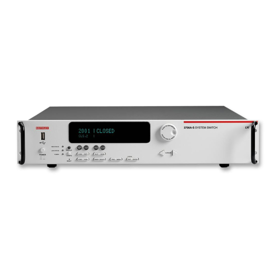
Section 2: Using the Front Panel Series 3700 System Switch/Multimeter User's Manual Figure 2-2: Model 3706-S System Switch (no DMM) NOTE If your model does not have a front panel, please refer to the reference manual for information on how to change: 1. -
Page 25: Display
Series 3700 System Switch/Multimeter User's Manual Section 2: Using the Front Panel Figure 2-3: Model 3706-NFP System Switch/Multimeter Figure 2-4: Model 3706-SNFP System Switch (no DMM) Display The Series 3700 display provides visual information on the present active channel. The display, with the wheel, provides a means to change the active channel or channel ranges, as well as access to view and edit the various menus and menu items. -
Page 26: Figure 2-5: Active Channel Display Example
Section 2: Using the Front Panel Series 3700 System Switch/Multimeter User's Manual NOTE Attribute lists, as well as menu lists, that are larger than the display, can be accessed by turning the wheel (6). Displayed arrows (5) indicate additional attributes (or menu items, as applicable) are available for access by turning the wheel (6) in the direction the arrow points. - Page 27 Series 3700 System Switch/Multimeter User's Manual Section 2: Using the Front Panel The bottom line of the display (4) contains the attribute symbols. The symbols that appear are dependent on whether the attribute exists for the selected function. If the symbol has also contains a value, the third column in the table indicates the value definition.
-
Page 28: Front Panel Keys
Section 2: Using the Front Panel Series 3700 System Switch/Multimeter User's Manual See the following figure for a menu example. In the example, the MAIN MENU is displayed. Turn the wheel (6) or press the cursor keys, to scroll through the available menu items. In the following figure's first display, there is a right arrow indicator. -
Page 29: Operation Keys
Series 3700 System Switch/Multimeter User's Manual Section 2: Using the Front Panel CONFIG key Use this key to access the an attribute menu that enables you to configure channels, channel patterns, DMM functions, or settings, reading buffer, scans, and other operations. Refer to the following for additional information: CHAN key configuration (on page 2-8) - Page 30 Section 2: Using the Front Panel Series 3700 System Switch/Multimeter User's Manual CHAN key configuration Pressing the CONFIG key and then the CHAN key opens the CHANNEL ATTRibute MENU. This menu contains: LABEL: This menu item sets the label associated with the channels specified. Related ICL command: channel.setlabel.
- Page 31 Series 3700 System Switch/Multimeter User's Manual Section 2: Using the Front Panel VIEW: This menu item shows the channels associated with the pattern. Note that if no patterns exist in the system when the PATT key is pressed, then this will be the only menu item displayed in the PATTERN ACTION MENU.
- Page 32 Section 2: Using the Front Panel Series 3700 System Switch/Multimeter User's Manual SCAN key configuration Pressing the CONFIG key and then the SCAN key opens the "SCAN ATTR MENU" that contains: ADD: This menu item instructs how to add an additional list of channels and/or channel patterns to scan.
- Page 33 Series 3700 System Switch/Multimeter User's Manual Section 2: Using the Front Panel DMM key configuration Pressing the CONFIG key and then the DMM key opens a DMM attribute menu for the active function. For example, if the DCV function is active, pressing the CONFIG key and then the DMM key opens the DC VOLT ATTR MENU.
- Page 34 Section 2: Using the Front Panel Series 3700 System Switch/Multimeter User's Manual INPUTDIV Enables or disables the 10M ohm input divider. Related ICL command: dmm.inputdivider LIMIT Opens the LIMIT MENU for the selected DMM function. See LIMIT key configuration (on page 2- 14).
- Page 35 Series 3700 System Switch/Multimeter User's Manual Section 2: Using the Front Panel OPENDETECT Configures the state of the thermocouple or four-wire ohms open detector being used. Related ICL command: dmm.opendetector RANGE Configures the range of DMM for the selected function. Related ICL command: dmm.range Opens the REL MENU for the selected DMM function.
- Page 36 Section 2: Using the Front Panel Series 3700 System Switch/Multimeter User's Manual LIMIT key Pressing this key will cycle through the four combinations of limit state settings (Limit1 and Limit2 off, Limit1 on and Limit2 off, Limit1 off and Limit2 on, Limit1 and Limit2 on). LIMIT key configuration Pressing the CONFIG key and then the LIMIT key opens the LIMIT MENU.
- Page 37 Series 3700 System Switch/Multimeter User's Manual Section 2: Using the Front Panel FILTER key Pressing this key enables/disables filter for selected function. When the filter is enabled, the FILT annunciator will light. Also see Filter in the reference manual. FILTER key configuration Pressing the CONFIG key and then the FILTER key opens the FILTER MENU.
- Page 38 Section 2: Using the Front Panel Series 3700 System Switch/Multimeter User's Manual INSERT key Pressing this key appends the present channel to the scan list. DELETE key Pressing this key deletes the present channel (including function) from the scan list. If the present channel is not contained in the scan list, no error is reported.
-
Page 39: Range, Multifunction Keys, And Wheel
Series 3700 System Switch/Multimeter User's Manual Section 2: Using the Front Panel Range, multifunction keys, and wheel Range keys ▲▼ Selects the next higher or lower measurement range for the selected function when on measurement display. To set the range, use the RANGE keys ▲ or ▼. If the Series 3700 displays the overflow message on a particular range, select a higher range until an on-range reading is displayed. - Page 40 Section 2: Using the Front Panel Series 3700 System Switch/Multimeter User's Manual OPEN key Opens selected channels or channel pattern. CLOSE Key Closes specified channels or channel pattern. STORE key Opens the RD BUFF ACTION MENU. This menu contains: CREATE: Allows creation of a reading buffer, or allows you to select a previously created reading buffer.
- Page 41 Series 3700 System Switch/Multimeter User's Manual Section 2: Using the Front Panel FUNCtion key This key select the active function by cycling through the following list as listed. Each press of the FUNC key has the DMM and configured to the next function in the list: dcvolts: DC voltage acvolts: AC voltage dccurrent: DC current...
-
Page 43: Rear Panel
Section 3 Rear Panel In this section: Rear panel summary ..................3-1 Rear panel connections ................... 3-2 Switching module installation and connections ..........3-6 Module installation ..................3-6 Bus operation ....................3-10 Power-up ......................3-11 Rear panel summary Figure 3-1: Rear panel features Item Description Analog backplane fuse... -
Page 44: Rear Panel Connections
(on page 8-1) for details. Slots Use any of the six slots of the Keithley Instruments Series 3700 for the switching modules. When a module is not installed, make sure to cover the slot with a slot cover. For additional... -
Page 45: Digital I/O Port
NOTE High Current Pins (10-14) can be used for binning applications or for external relays. Connecting cables Use a cable equipped with a standard male DB-25 connector (Keithley Instruments part number CA-126-1). Document Number: 3700S-900-01 Rev. A / August 2007... -
Page 46: Gpib Connector
600mA. This line is protected by a self-resetting fuse (one hour recovery time). GPIB connector For GPIB communication, connect to GPIB port of computer using an IEEE-488 cable (Keithley Instruments Model 7007). Ethernet connector (RJ-45) For Ethernet communication, connect to Ethernet port of a computer, or to a hub or receptacle of an Ethernet system. -
Page 47: Analog Backplane Connector
Series 3700 System Switch/Multimeter User's Manual Section 3: Rear Panel Figure 3-3: USB connectors Analog backplane connector Refer to the following figure for analog backplane connector information. See Connections page 3-8) before making any connections. Figure 3-4: Analog backplane connector The table below contains pin numbers and descriptions for the analog backplane connector. -
Page 48: Switching Module Installation And Connections
Section 3: Rear Panel Series 3700 System Switch/Multimeter User's Manual Switching module installation and connections In order to exercise close/open operations explained in this section, a switching module (or pseudocard) must be installed in the mainframe. A switching module can be installed by the user, however external connections to the switching module are only to be performed by qualified service personnel. -
Page 49: Figure 3-5: Typical Module Installation
Series 3700 System Switch/Multimeter User's Manual Section 3: Rear Panel 7. Press the SLOT (on page 2-9) to see the model numbers, description, and the firmware revision of the installed switching module(s), along with the mainframe firmware and DMM (if present). -
Page 50: Connections
Section 3: Rear Panel Series 3700 System Switch/Multimeter User's Manual Connections WARNING Connection information for switching modules is intended for qualified service personnel. Do not attempt to connect DUT or external circuitry to a switching module unless qualified to do so. To prevent electric shock that could result in serious injury or death, comply with these safety precautions: Before making or breaking any connections to the switching module,... -
Page 51: Pseudocards
This allows a saved setup to be recalled provided the installed card (or pseudocard) matches the model number for the slot in the saved setup. Pseudocards programming example Use the following command line to set the pseudocard of Slot 6 for 3720 Dual 1 x 30 Multiplexer card simulation: slot[6].pseudocard = slot.PSEUDO_3720 Channel assignments Each switching module has a certain number of channels. -
Page 52: Bus Operation
Section 3: Rear Panel Series 3700 System Switch/Multimeter User's Manual Bus operation The Series 3700 supports bus operation over USB, Ethernet and GPIB. The GPIB settings may be set from the front panel, or once controlled by the bus, over the bus. 1. -
Page 53: Power-Up
Series 3700 System Switch/Multimeter User's Manual Section 3: Rear Panel 2. rawsocket is 5025 (ICL: lan.status.port.rawsocket) 3. vxi11 is 1024 (ICL: lan.status.port.vxi11) 4. dead socket termination is 5030 (ICL: lan.status.port.dst) When changing between the various bus interfaces, send the abort command to have that interface become the active one for receiving and processing bus commands. -
Page 54: Power-Up Sequence
Error and status messages contained in the Reference manual.) NOTE If a problem develops while the instrument is under warranty, return it to Keithley Instruments, Inc., for repair. Assuming no errors occur, the Series 3700 will power-up as follows: 1. -
Page 55: System Identification
Series 3700 System Switch/Multimeter User's Manual Section 3: Rear Panel System identification Serial number, firmware revision, and calibration dates can be displayed by selecting the SYSTEM-INFO item of the main menu (press MENU > SYSTEM-INFO). Select FIRMWARE, SERIAL#, or CAL as desired. For remote programming, use the *IDN? query to read system information. -
Page 57: Closing And Opening Switching Module Channels
Section 4 Closing and Opening Switching Module Channels In this section: Close/open overview ..................4-1 Channel operation ................... 4-13 Identifying installed modules and viewing closed channels ....... 4-15 Break Before Make and connecting sequentially ..........4-16 Relay closure count ..................4-17 Close/open overview NOTE This section provides basic close/open information for switching module channels. -
Page 58: Channel Operation (Non-Channel Pattern Operation)
Section 4: Closing and Opening Switching Module Channels Series 3700 System Switch/Multimeter User's Manual Channel pattern operation: This mode of operation provides additional flexibility by providing individual control of each switching module and backplane channel. Careless operation in this mode could create a safety hazard and/or damage the switching module and other equipment. Channel pattern operation should only be used by experienced test engineers. - Page 59 Series 3700 System Switch/Multimeter User's Manual Section 4: Closing and Opening Switching Module Channels NOTE Matrix and multiplexer channels, along with backplane relays, may be part of a channel pattern image. A channel pattern is comprised of multiple channels and/or backplane relays (minimum of two). The channels may be mux (multiplexer), matrix, or analog backplane relay channels and is created by the user.
- Page 60 Therefore, the paired channel does not need to be specified in the channel image manually. For example, assume Slot 1 has a 3720 card installed and all channels are set to 4-pole operation. With all channels configured for 4-pole, the available channels are 1001 to 1030.
-
Page 61: Close/Open Commands And Operation
Series 3700 System Switch/Multimeter User's Manual Section 4: Closing and Opening Switching Module Channels To see the image associated with a channel pattern, use the channel.pattern.getimage command. For example to see the image of the pattern just created called 'one4wire': print(channel.pattern.getimage('one4wire')) o 1001(1031),1911,1922 NOTE Paired channel are indicated in parenthesis... -
Page 62: Close/Open Bus Operation
Section 4: Closing and Opening Switching Module Channels Series 3700 System Switch/Multimeter User's Manual Available commands for measuring: dmm.close dmm.open scanning (only with function of DMM configuration set to anything other than 'nofunction') Action performed dmm.close Equivalent of channel.exclusiveslotclose except it also prepares the DMM for taking a measurement on the function associated with the item. -
Page 63: Close/Open Key Operation
Series 3700 System Switch/Multimeter User's Manual Section 4: Closing and Opening Switching Module Channels Close/open key operation The front panel CLOSE and OPEN keys operate in the same manner as one of the following: channel.close and channel.open commands dmm.close and dmm.open commands The operation of the keys depend on the selected channel or channel patterns function association. -
Page 64: Duality With Example
Section 4: Closing and Opening Switching Module Channels Series 3700 System Switch/Multimeter User's Manual close count: indicates how many times the relay for a channel has closed. A backplane relay has a close count associated with it as well. DMM configuration: indicates the DMM function tied to a mux channel along with that function's pertinent attributes. - Page 65 Series 3700 System Switch/Multimeter User's Manual Section 4: Closing and Opening Switching Module Channels Assume the following channel attributes: Channel Backplane relays Pole setting DMM configuration 3001 none 'fourwireohms' 3002 3915 'fourwireohms' 3031 3921 N/A (paired channel) 3032 3921 N/A (paired channel) NOTE The reason that 3031 and 3032 are paired channels (in this is example) is that the channels 3001 and 3002 are configured with a DMM setting of "fourwireohms"...
-
Page 66: Channel And Backplane Notation
Section 4: Closing and Opening Switching Module Channels Series 3700 System Switch/Multimeter User's Manual 7. dmm close 3002 open 3001, 3031 keep 3911, 3922 close close 3002, 3032 When creating a channel pattern, make sure to: include all of the channels and backplane relays that are needed for that channel pattern image. -
Page 67: Figure 4-1: Multiplexer Card Display
Series 3700 System Switch/Multimeter User's Manual Section 4: Closing and Opening Switching Module Channels Analog backplane relays (bank 2 of Slot 1) examples: Reference Analog backplane relay 1921 analog backplane relay 1 1922 analog backplane relay 2 1923 analog backplane relay 3 1924 analog backplane relay 4 1925... -
Page 68: Channel List Parameter
Section 4: Closing and Opening Switching Module Channels Series 3700 System Switch/Multimeter User's Manual Matrix card notation To control channels using matrix card notation, use SRCC where: S: Slot number R: Row number CC: Column number (always use 2 digits) Matrix channel examples: Reference Slot... -
Page 69: Channel Operation
Series 3700 System Switch/Multimeter User's Manual Section 4: Closing and Opening Switching Module Channels Enclose the contents of the channel list in either single (') or double (") quotes, but the quote style must match. Use a comma or semicolon to separate the channel list or channel patterns. The string may contain a single channel, channel pattern or analog backplane relay as well as multiple ones that are indicated by a range or comma separated. -
Page 70: 2-Wire Functions
Section 4: Closing and Opening Switching Module Channels Series 3700 System Switch/Multimeter User's Manual 2-wire functions The following figure shows an example of how the channel is connected to the DMM Input of the Series 3700 with regards to a 2-wire function, such as DC volts. Assume a switching module with 20 channels is installed in Slot 1 of the mainframe. -
Page 71: Identifying Installed Modules And Viewing Closed Channels
Series 3700 System Switch/Multimeter User's Manual Section 4: Closing and Opening Switching Module Channels Assume a switching module is installed in Slot 1 of the mainframe, and a 4-wire function, such as Ω4, is selected. When Channel 1001 is closed using the Close key, the Channel 1 relay and the input backplane isolation relay (Channel 1911) closes to connect the channel to DMM Input. -
Page 72: Break Before Make And Connecting Sequentially
Section 4: Closing and Opening Switching Module Channels Series 3700 System Switch/Multimeter User's Manual Example Assume a Model 3722 is installed in Slot 1, a Model 3721 is installed in Slot 2 and the other 4 slots are empty. Sending the following command line over the bus: for x=1,6 do print (slot[x].idn) end The response would be: 3722, Dual 1x48 Multiplexer, 01.00a, <Module Serial Number>... -
Page 73: Relay Closure Count
Series 3700 System Switch/Multimeter User's Manual Section 4: Closing and Opening Switching Module Channels 4. From this menu, select one of the following: RULE: Use this menu item to set the rule to BBM, MBB, or OFF. SEQUENTIAL. Use this menu item connect sequentially (ON or OFF setting). 5. - Page 74 Section 4: Closing and Opening Switching Module Channels Series 3700 System Switch/Multimeter User's Manual 2. Press the CONFIG key. 3. Press the CHAN key. 4. Use the wheel (3) to scroll to the "COUNT" menu item. 5. Press the ENTER key (or the wheel) to display the close counts for Channel 1003 through 1005.
-
Page 75: Basic Digital Multimeter (Dmm) Operation
Section 5 Basic Digital Multimeter (DMM) Operation In this section: DMM measurement capabilities ............... 5-1 High-energy circuit safety precautions .............. 5-2 Performance considerations ................5-3 Voltage measurements (DCV and ACV)............5-4 Current measurements (DCI and ACI) ............. 5-15 AMPS analog backplane fuse replacement ............5-16 Resistance measurements ................ -
Page 76: High-Energy Circuit Safety Precautions
Section 5: Basic Digital Multimeter (DMM) Operation Series 3700 System Switch/Multimeter User's Manual High-energy circuit safety precautions To optimize safety when measuring voltage in high-energy distribution circuits, read and use the directions in the following warning: WARNING Dangerous arcs of an explosive nature in a high-energy circuit can cause severe personal injury or death. -
Page 77: Performance Considerations
Series 3700 System Switch/Multimeter User's Manual Section 5: Basic Digital Multimeter (DMM) Operation Performance considerations Warm-up After the Series 3700 is turned on, it must be allowed to warm up for at least two hours to allow the internal temperature to stabilize. If the instrument has been exposed to extreme temperatures, allow extra warm-up time. -
Page 78: Line Cycle Synchronization
Section 5: Basic Digital Multimeter (DMM) Operation Series 3700 System Switch/Multimeter User's Manual Line cycle synchronization Synchronizing A/D conversions with the frequency of the power line increases common mode and normal mode noise rejection. When line cycle synchronization is enabled, the measurement is initiated at the first positive-going zero crossing of the power line cycle after the trigger. -
Page 79: Dcv Input Divider
Series 3700 System Switch/Multimeter User's Manual Section 5: Basic Digital Multimeter (DMM) Operation DCV input divider Normally, the input resistance for the 100mVDC, 1VDC, and 10VDC ranges is >10GΩ, while the input resistance of the 100VDC and 300VDC ranges is 10MΩ. However, the input resistance for the three lower DCV ranges can also be set to 10MΩ... -
Page 80: Figure 5-2: Dcv Connection
Section 5: Basic Digital Multimeter (DMM) Operation Series 3700 System Switch/Multimeter User's Manual WARNING Make sure the insulation and wire sizes used are appropriate for the voltages and current being applied to the Series 3700 analog backplane connector. Use supplementary insulation as needed. Exceeding the voltage rating of a wiring may cause damage and create a safety hazard. -
Page 81: Schematic
Series 3700 System Switch/Multimeter User's Manual Section 5: Basic Digital Multimeter (DMM) Operation Schematic Refer to the following figure for a schematic of the rear panel, backplane, and DMM connect relays with a typical card. Figure 5-4: Rear panel to backplane to DMM connect relays schematic Document Number: 3700S-900-01 Rev. -
Page 82: Voltage Measurement Procedure
Section 5: Basic Digital Multimeter (DMM) Operation Series 3700 System Switch/Multimeter User's Manual Voltage measurement procedure WARNING If both the analog backplane connector and a switching module's terminals are connected at the same time, all wiring and connections must be rated to the highest voltage that is connected. For example, if 300V is connected to the analog backplane connector, the test lead insulation for the switching module must also be rated for 300V. -
Page 83: Ac Voltage Measurements And Crest Factor
Series 3700 System Switch/Multimeter User's Manual Section 5: Basic Digital Multimeter (DMM) Operation AC voltage measurements and crest factor The root-mean-square (RMS) value of any periodic voltage or current is equal to the value of the DC voltage or current which delivers the same power to a resistance as the periodic waveform does. -
Page 84: Figure 5-6: Acv Measurements: Square, Pulse, And Sawtooth Waves
Section 5: Basic Digital Multimeter (DMM) Operation Series 3700 System Switch/Multimeter User's Manual Figure 5-6: ACV measurements: square, pulse, and sawtooth waves The Series 3700 is an AC-coupled RMS meter. For an AC waveform with DC content, the DC component is removed before the RMS is calculated. This affects the crest factor because the peak value for the DC-coupled waveform is different than the peak value for the AC-coupled waveform. -
Page 85: Speed, Accuracy, And Settling Times For Ac Current And Voltage
Series 3700 System Switch/Multimeter User's Manual Section 5: Basic Digital Multimeter (DMM) Operation The reason to consider crest factor in accuracy of RMS measurements is because the meter has a limited bandwidth. Theoretically, a sine wave can be measured with a finite bandwidth because all of its energy is contained in a single frequency. - Page 86 Section 5: Basic Digital Multimeter (DMM) Operation Series 3700 System Switch/Multimeter User's Manual When detectorbandwidth = 300 For dmm.detectorbandwidth=300, the Series 3700 DMM is optimized for inputs from 300kHz, (FAST). For ACI or ACV inputs t300Hz, the RMS converter is | DC output. The A/D takes a single measurement to determine the RMS measurement.
- Page 87 Series 3700 System Switch/Multimeter User's Manual Section 5: Basic Digital Multimeter (DMM) Operation Function Range and delays Ranges 10mA 100mA Autodelay 200ms 200ms 200ms 200ms 200ms Auto Range 300ms 300ms 300ms 300ms 300ms Ranges 1- 100: 10k: 100k: 10M: 100M: :2 and :4 Autodelay 13ms...
-
Page 88: Low Level Considerations
Section 5: Basic Digital Multimeter (DMM) Operation Series 3700 System Switch/Multimeter User's Manual Low level considerations For sensitive measurements, external considerations beyond the Series 3700 affect the accuracy. Effects not noticeable when working with higher voltages are significant in microvolt signals. -
Page 89: Current Measurements (Dci And Aci)
Series 3700 System Switch/Multimeter User's Manual Section 5: Basic Digital Multimeter (DMM) Operation AC voltage offset The Series 3700, at 5½ digits resolution, will typically display 100 counts of offset on AC volts with the input shorted. This offset is caused by the offset of the TRMS converter. This offset will not affect reading accuracy and should not be zeroed out using the REL feature. -
Page 90: Amps Analog Backplane Fuse Replacement
3. Remove the fuse and replace it with the same type (3A, 250V, fast-blow, 5 × 20mm). The Keithley Instruments part number is FU-99-1. 4. Install the new fuse by reversing the procedure above. -
Page 91: Resistance Measurements
Series 3700 System Switch/Multimeter User's Manual Section 5: Basic Digital Multimeter (DMM) Operation Resistance measurements The Series 3700 uses the constant-current method to measure resistance ranges from 1: to 1M:. The Series 3700 sources a constant current (I) to the resistance and measures the voltage (V). -
Page 92: Figure 5-7: Two-Wire Resistance Measurements
Section 5: Basic Digital Multimeter (DMM) Operation Series 3700 System Switch/Multimeter User's Manual For 2-wire resistance measurements (:2), connect the leads to INPUT HI and LO. Figure 5-7: Two-wire resistance measurements For 4-wire resistance (:4), connect the leads to INPUT HI and LO, and sense :4 HI and LO. Figure 5-8: Four-wire resistance measurement 5-18 Document Number: 3700S-900-01 Rev. -
Page 93: Figure 5-9: Two-Wire Switching Module Resistance Connection
Series 3700 System Switch/Multimeter User's Manual Section 5: Basic Digital Multimeter (DMM) Operation Switching module Connections for the switching module are shown below. As shown, each of the 40 channels can be used to perform 2W: measurements. Figure 5-9: Two-wire switching module resistance connection For 4W: measurements, a channel pair is used for each 4-wire measurement as shown. -
Page 94: Standard Resistance Measurements
Section 5: Basic Digital Multimeter (DMM) Operation Series 3700 System Switch/Multimeter User's Manual Standard resistance measurements CAUTION Inputs: Do not apply more than 425V peak between INPUT HI and LO, or instrument damage may occur. CAUTION Switching cards: Do not apply more than 300V DC or 300V RMS (425V peak) for AC waveforms between any two pins, or switching module damage may occur. -
Page 95: Figure 5-11: Enabling Offset-Compensated Ohms
Series 3700 System Switch/Multimeter User's Manual Section 5: Basic Digital Multimeter (DMM) Operation NOTE The various instrument operations, including OCOMP, are performed on the input signal in a sequential manner. For a normal resistance measurement, the Series 3700 sources a current (I) and measures the voltage (V). -
Page 96: Figure 5-12: Four-Wire Ohm Attr Menu: Offsetcomp
Section 5: Basic Digital Multimeter (DMM) Operation Series 3700 System Switch/Multimeter User's Manual 1. Press the CONFIG key (1). 2. Press the DMM key (2). 3. Turn the wheel (3) to scroll to the "OFFSETCOMP" menu item and press the wheel to select. -
Page 97: Dry Circuit Ohms (Dry+)
Series 3700 System Switch/Multimeter User's Manual Section 5: Basic Digital Multimeter (DMM) Operation With offset-compensated ohms enabled, it will be “remembered” by the 4W: function after you change measurement functions (i.e., DCV). When 4W: is again selected, offset-compensated ohms will be enabled. dmm.offsetcompensation is a common ICL command and is shared with fourwireohms, dryciruit, threertd and fourrtd. -
Page 98: Figure 5-13: Enabling Dry-Circuit Ohms
Section 5: Basic Digital Multimeter (DMM) Operation Series 3700 System Switch/Multimeter User's Manual NOTE When dry circuit ohms is enabled, offset-compensated ohms is automatically enabled (OC+ annunciator). If you do not wish to use offset-compensated ohms, after setting dry circuit ohms, disable offset-compensated ohms using the information in Enabling/disabling offset-compensated ohms (see "Enabling/disabling offset- compensated ohms"... - Page 99 Series 3700 System Switch/Multimeter User's Manual Section 5: Basic Digital Multimeter (DMM) Operation NOTE When enabled, the dry circuit ohms annunciator is on (DRY+). Performing dry circuit ohms measurements Dry circuit ohms can only be performed on the 4W: function using the 1:, 10:, 100:, 1k: or 10k: ranges (maximum resistance of 2.4k:).
-
Page 100: Measurement Methods
Section 5: Basic Digital Multimeter (DMM) Operation Series 3700 System Switch/Multimeter User's Manual Dry circuit ohms measurement considerations Dry circuit ohms uses a constant current source with voltage monitoring that is used to clamp the current source voltage. The current source will remain constant as long as the monitoring voltage is <20mV. -
Page 101: Figure 5-15: Two-Wire Constant-Current Source Method
Series 3700 System Switch/Multimeter User's Manual Section 5: Basic Digital Multimeter (DMM) Operation The two-wire constant-current method is shown below. Figure 5-15: Two-wire constant-current source method The four-wire constant-current method is shown below. Figure 5-16: Four-wire constant-current source method Ratiometric method For the 10M: and 100M: ranges, the ratiometric method is used to measure resistance. -
Page 102: Figure 5-17: Two-Wire Ratiometric Method
Section 5: Basic Digital Multimeter (DMM) Operation Series 3700 System Switch/Multimeter User's Manual Basic circuit theory dictates that I is equal to the I . Since the voltmeter of the Series 3700 ) has very high input impedance (>10G:), current through the voltmeter branch is MEAS insignificant and can be discounted. -
Page 103: Figure 5-18: Four-Wire Ratiometric Method
Series 3700 System Switch/Multimeter User's Manual Section 5: Basic Digital Multimeter (DMM) Operation Keep in mind that V includes the voltage drops of the input test leads (Input HI and Input LO). MEAS Therefore, the actual voltage drop across the DUT is V minus the two voltage drops in the MEAS test leads. -
Page 104: Open Lead Detection
Section 5: Basic Digital Multimeter (DMM) Operation Series 3700 System Switch/Multimeter User's Manual Open lead detection The Series 3700 has four methods to detect open lead conditions: ISOUR open voltage VMEAS open voltage Calculated measurement dmm.opendetector The following figures contains open lead detection schematics for various measurements. Figure 5-19: Simplified Dry-Circuit open lead detection schematic 5-30 Document Number: 3700S-900-01 Rev. -
Page 105: Figure 5-20: Simplified Normal Four-Wire Open Lead Detection Schematic
Series 3700 System Switch/Multimeter User's Manual Section 5: Basic Digital Multimeter (DMM) Operation Figure 5-20: Simplified normal four-wire open lead detection schematic ISOUR open voltage 1: through 1M: ranges: A hardware detector is used to detect an open input lead. The hardware detector uses a comparator circuit to monitor the voltage on the ohm I SOUR OPEN-HI-LEAD... - Page 106 Section 5: Basic Digital Multimeter (DMM) Operation Series 3700 System Switch/Multimeter User's Manual Calculated measurement open voltage A calculated measurement, which exceed 120% of the range, will return an overflow reading. dmm.opendetector open voltage With dmm.opendetector = dmm.ON, a separate -1.5 A I SHI and a separate SLO current OPENLEAD source, will pulse on and off before the start of each measurement while I...
- Page 107 1.0. OPENLEAD 4. Additional cable and 3700 card capacitance can increase settle times, resulting additional measurement uncertainty. Keithley Instruments recommend the use of Teflon or other low- dielectric absorption wire insulation for these measurements. Four-wire dry-circuit open lead detection...
-
Page 108: Figure 5-21: Simplified Dry-Circuit Open V-Clamp Feedback Loop Schematic
Section 5: Basic Digital Multimeter (DMM) Operation Series 3700 System Switch/Multimeter User's Manual The follow schematic provides a simplified view of the Series 3700 four-wire dry-circuit open lead detection. Figure 5-21: Simplified Dry-Circuit open V-clamp feedback loop schematic Dry-clamp open lead detector (dry-circuit) A hardware detector is used to detect an open input lead. -
Page 109: Temperature Measurements
Series 3700 System Switch/Multimeter User's Manual Section 5: Basic Digital Multimeter (DMM) Operation NOTE 1. INPUT Sense HI is internally connector to INPUT HI. The connection allows proper open circuit voltage, even with Sense HI disconnected. With INPUT Sense HI disconnected, and the other inputs properly connected, the measurement will read the and R drop. - Page 110 Section 5: Basic Digital Multimeter (DMM) Operation Series 3700 System Switch/Multimeter User's Manual Reference junctions A reference junction is the cold junction in a thermocouple circuit that is held at a stable, known temperature. The cold junction is where dissimilar wire connections must be made. As long as the temperature of the cold junction is known, the Series 3700 can factor in the reference temperature to calculate the actual temperature reading at the thermocouple.
- Page 111 Series 3700 System Switch/Multimeter User's Manual Section 5: Basic Digital Multimeter (DMM) Operation Open thermocouple detection Long lengths of thermocouple wire can have a large amount of capacitance that is seen at the input of the DMM. If an intermittent open occurs in the thermocouple circuit, the capacitance can cause an erroneous on-scale reading.
-
Page 112: Figure 5-22: Simplified T/C Open Lead Detection Schematic
Section 5: Basic Digital Multimeter (DMM) Operation Series 3700 System Switch/Multimeter User's Manual The thermocouple open detection times are listed in the following table. Ioff IOPENL Phase Internal Source Source Internal DMM Line Settle Settle Measure Comm. Freq Measurement Comm. (msec) (msec) (msec) - Page 113 Series 3700 System Switch/Multimeter User's Manual Section 5: Basic Digital Multimeter (DMM) Operation Thermocouple connections Connections for thermocouples are shown below. Thermocouples are color coded to identify the positive (+) and negative (-) leads (see the table). Note that the negative (-) lead for U.S. type T/Cs is red.
-
Page 114: Figure 5-23: Simulated Reference Junction
Section 5: Basic Digital Multimeter (DMM) Operation Series 3700 System Switch/Multimeter User's Manual When using the Series 3700 analog backplane connector, use a simulated reference junction for thermocouple temperature measurements. An ice bath, as shown below, serves as an excellent cold junction since it is relatively easy to hold the temperature to 0°C. -
Page 115: Thermistors
Series 3700 System Switch/Multimeter User's Manual Section 5: Basic Digital Multimeter (DMM) Operation Thermocouple temperature measurement configuration To configure temperature measurements from the front panel: 1. If needed, change to the temperature function ("TMP" is displayed) by pressing the FUNC key. -
Page 116: Figure 5-26: Thermistor Analog Backplane Connection
Section 5: Basic Digital Multimeter (DMM) Operation Series 3700 System Switch/Multimeter User's Manual Of all the temperature transducers, the thermistor is the most sensitive. It can detect minute changes in temperature. It is a good choice when measuring slight changes in temperature. The downside for this increased sensitivity is the loss of linearity. -
Page 117: Rtds (Resistance Temperature Detector)
Series 3700 System Switch/Multimeter User's Manual Section 5: Basic Digital Multimeter (DMM) Operation 4. Set THERMO device attributes: Turn the wheel to scroll to the "THERMO" menu item and press the ENTER key. Turn the wheel to scroll to the "THERMISTOR" temperature connection and press the ENTER key. -
Page 118: Figure 5-28: Three-Wire Rtd Connections
Section 5: Basic Digital Multimeter (DMM) Operation Series 3700 System Switch/Multimeter User's Manual NOTE dmm.offsetcompensation is a common command, shared with fourwireohms and drycircuit. To enable or disable RTD offset compensation, first select the temperature function, next the transducer, and lastly, the offset compensation state. Figure 5-28: Three-wire RTD connections Figure 5-29: Three-wire RTD switching module connections 5-44... -
Page 119: Figure 5-30: Four-Wire Rtd Connections
Series 3700 System Switch/Multimeter User's Manual Section 5: Basic Digital Multimeter (DMM) Operation 4-wire RTD connections Shown below are 4-wire RTD connections to the Series 3700. For a 4-wire RTD capable 40- channel switching module, paired channels are used to perform the 4-wire measurement. For example, the two input leads of the RTD are connected to a primary channel (1 through 20), while the two sense leads are connected to its paired channel (21 through 40). -
Page 120: Temperature Measurement Configuration
Section 5: Basic Digital Multimeter (DMM) Operation Series 3700 System Switch/Multimeter User's Manual Type Standard Alpha Beta Delta Ω at 0°C PT100 ITS-90 0.00385055 0.10863 1.49990 100Ω D100 ITS-90 0.003920 0.10630 1.49710 100Ω F100 ITS-90 0.003900 0.11000 1.49589 100Ω PT385 IPTS-68 0.003850 0.11100... -
Page 121: Temperature Measurement Procedure
Series 3700 System Switch/Multimeter User's Manual Section 5: Basic Digital Multimeter (DMM) Operation The temperature measurement can be configured from the front panel when the present function is "TMP" by pressing the CONFIG key, then the DMM key. Front panel cursor position is indicated by a flashing menu item or parameter and is controlled by the◄... -
Page 122: Frequency And Period Measurements
Section 5: Basic Digital Multimeter (DMM) Operation Series 3700 System Switch/Multimeter User's Manual 5. If using a switching module, perform the following steps to close the desired channel. Keep in mind, that for 3 or 4-wire RTD measurements, you will close the primary (INPUT) channel (1 through 10). -
Page 123: Frequency Connections
Series 3700 System Switch/Multimeter User's Manual Section 5: Basic Digital Multimeter (DMM) Operation The Series 3700 completes a reading when it receives its first positive zero-crossing after the gate time expires. For example, for any arbitrary frequency, you may wait up to the gate time plus two times the period of the input waveform before the Series 3700 returns a reading. -
Page 124: Continuity Testing
Section 5: Basic Digital Multimeter (DMM) Operation Series 3700 System Switch/Multimeter User's Manual 3. Press the CONFIG key and then the DMM key. The "CONT ATTR MENU" will open. 4. Set threshold voltage: Turn the wheel to scroll to the "THRESHOLD" menu item (right most menu item) and press the ENTER key. -
Page 125: Continuity Testing Connections
Series 3700 System Switch/Multimeter User's Manual Section 5: Basic Digital Multimeter (DMM) Operation Continuity testing connections When using the rear analog backplane connector, connect the test leads to the INPUT HI and LO terminals as shown below. Figure 5-34: Continuity connections Connections to test continuity using a switching module are shown below. - Page 126 Section 5: Basic Digital Multimeter (DMM) Operation Series 3700 System Switch/Multimeter User's Manual 4. Set threshold resistance: Turn the wheel to scroll to the "THRESHOLD" menu item (right most menu item) and press the ENTER key. Using the wheel, dial in the desired resistance to be used as a threshold (1:–1000: . Press the ENTER key to set.
-
Page 127: Icl Command List
Section 6 ICL Command List This section provides a listing of Instrument Control Library commands, descriptions, and usage. Refer to the reference manual for complete ICL usage information. In this section: beeper ......................6-2 bit functions ....................6-2 channel functions and attributes ..............6-2 delay function.................... -
Page 128: Beeper
Section 6: ICL Command List Series 3700 System Switch/Multimeter User's Manual beeper The beeper generates a beep tone. It is typically used to announce the start and/or completion of a test or operation. Available commands: beeper.enable beeper.beep() bit functions The bit functions are used to perform bitwise logic operations on two given numbers, and bit operations on one given number. - Page 129 Series 3700 System Switch/Multimeter User's Manual Section 6: ICL Command List channel.connectsequential channel.exclusiveclose() channel.exclusiveslotclose() channel.getbackplane() channel.getclose() channel.getcount() channel.getdelay() channel.getforbidden() channel.getimage() channel.getlabel() channel.getpole() channel.getstate() channel.open() channel.pattern.catalog() channel.pattern.delete() channel.pattern.getimage() channel.pattern.setimage() channel.pattern.snapshot() channel.reset() channel.setbackplane() channel.setdelay() channel.setforbidden() channel.setlabel() channel.setpole() Document Number: 3700S-900-01 Rev. A / August 2007...
-
Page 130: Delay Function
Section 6: ICL Command List Series 3700 System Switch/Multimeter User's Manual delay function This function is used to postpone system operation for a specified period of time. Available command: delay() digio functions and attributes Use the functions and attributes in this group to control read/write and trigger operations for the digital I/O Port. -
Page 131: Dmm Functions
Series 3700 System Switch/Multimeter User's Manual Section 6: ICL Command List display.getcursor() display.getlastkey() display.gettext() display.inputvalue() display.loadmenu.add display.loadmenu.delete() display.locallockout display.menu() display.prompt() display.screen display.sendkey() display.setcursor() display.settext() display.waitkey() dmm functions Use the functions and attributes in this group to control DMM operation, set limits, and perform calibration. - Page 132 Section 6: ICL Command List Series 3700 System Switch/Multimeter User's Manual dmm.calibration.dc() dmm.calibration.lock() dmm.calibration.password dmm.calibration.save() dmm.calibration.unlock() dmm.calibration.verifydate dmm.close() dmm.configure.catalog() dmm.configure.delete() dmm.configure.query() dmm.configure.recall() dmm.configure.set() dmm.connect dmm.dbreference dmm.detectorbandwidth dmm.displaydigits dmm.drycircuit dmm.filter.count dmm.filter.enable dmm.filter.type dmm.filter.window dmm.fourrtd dmm.func dmm.getconfig() dmm.inputdivider dmm.limit[Y].autoclear dmm.limit[Y].enable Document Number: 3700S-900-01 Rev. A / August 2007...
- Page 133 Series 3700 System Switch/Multimeter User's Manual Section 6: ICL Command List dmm.limit[Y].high.fail dmm.limit[Y].high.value dmm.limit[Y].low.fail dmm.limit[Y].low.value dmm.linesync dmm.makebuffer() dmm.math.enable dmm.math.format dmm.math.mxb.bfactor dmm.math.mxb.mfactor dmm.math.mxb.units dmm.math.percent dmm.measure() dmm.measurecount dmm.measurewithtime() dmm.nplc dmm.offsetcompensation dmm.open() dmm.opendetector dmm.range dmm.refjunction dmm.rel.acquire() dmm.rel.enable dmm.rel.level dmm.reset() dmm.rtdalpha dmm.rtdbeta Document Number: 3700S-900-01 Rev. A / August 2007...
-
Page 134: Eventlog Functions And Attributes
Section 6: ICL Command List Series 3700 System Switch/Multimeter User's Manual dmm.rtddelta dmm.rtdzero dmm.savebuffer() dmm.setconfig() dmm.simreftemperature dmm.thermistor dmm.thermocouple dmm.threertd dmm.threshold dmm.transducer dmm.units eventlog functions and attributes Use the functions and attributes in this group to control (read, write, enable, count, etc.,) the event log. -
Page 135: Exit Function
Series 3700 System Switch/Multimeter User's Manual Section 6: ICL Command List exit function Use this function to terminate a script that is presently running. Available command: exit() format attributes Use the format attributes to configure the output formats used by the printnumber and printbuffer functions. - Page 136 Section 6: ICL Command List Series 3700 System Switch/Multimeter User's Manual lan.config.dns.address[N] lan.config.dns.domain lan.config.dns.dynamic lan.config.dns.verify lan.config.duplex lan.config.gateway lan.config.ipaddress lan.config.method lan.config.speed lan.config.subnetmask lan.status.dns.address[index] lan.status.dns.hostname lan.status.duplex lan.status.gateway lan.status.ipaddress lan.status.macaddress lan.status.port.dst lan.status.port.rawsocket lan.status.port.telnet lan.status.port.vxi11 lan.status.reset() lan.status.speed lan.status.subnetmask lan.trigger[N].assert() lan.trigger[N].clear() lan.trigger[N].overrun lan.trigger[N].stimulus 6-10 Document Number: 3700S-900-01 Rev. A / August 2007...
-
Page 137: Localnode Attributes
Series 3700 System Switch/Multimeter User's Manual Section 6: ICL Command List lan.trigger[N].wait() localnode attributes Use the attributes in this group to set the power line frequency, control (on/off) prompting, control (hide/show) error messages on the display, to save/recall setup and other related local node capabilities. -
Page 138: Reset Function
Section 6: ICL Command List Series 3700 System Switch/Multimeter User's Manual reset function Use this function to return all logical instruments to the default settings. reset() scan functions Use the functions in this group to specify and configure channels and/or channel patterns to scan, as well as associated buffers, triggers, or other scanning aspects. -
Page 139: Setup Functions And Attribute
Series 3700 System Switch/Multimeter User's Manual Section 6: ICL Command List scan.trigger.channel.set() scan.trigger.channel.stimulus scan.trigger.clear() scan.trigger.measure.clear() scan.trigger.measure.set() scan.trigger.measure.stimulus scan.trigger.sequence.clear() scan.trigger.sequence.set() scan.trigger.sequence.stimulus setup functions and attribute Use the functions and attributes in this group to save and recall setups, and to set the power-on setup. -
Page 140: Status Function And Attributes
Section 6: ICL Command List Series 3700 System Switch/Multimeter User's Manual slot[X].endchannel.isolated slot[X].endchannel.voltage slot[X].idn slot[X].interlock.override slot[X].interlock.state slot[X].isolated slot[X].matrix slot[X].maxsettlingtime slot[X].maxvoltage slot[X].multiplexer slot[X].poles.four slot[X].poles.one slot[X].poles.two slot[X].pseudocard slot[X].startchannel.amps slot[X].startchannel.isolated slot[X].startchannel.voltage slot[X].tempsensor slot[X].thermal.state status function and attributes Refer to the reference manual for complete status ICL command information. Available commands: status.condition status.measurement.condition... - Page 141 Series 3700 System Switch/Multimeter User's Manual Section 6: ICL Command List status.measurement.ntr status.measurement.ptr status.node_enable status.node_event status.operation.condition status.operation..enable status.operation.event status.operation.ntr status.operation.ptr status.operation.user.condition status.operation.user.enable status.operation.user.event status.operation.user.ntr status.operation.user.ptr status.questionable.condition status.questionable.enable status.questionable.event status.questionable.ntr status.questionable.ptr status.request_enable status.request_event status.reset() status.standard.condition status.standard.enable status.standard.event status.system.condition status.system.enable Document Number: 3700S-900-01 Rev. A / August 2007 6-15...
-
Page 142: Timer Functions
Section 6: ICL Command List Series 3700 System Switch/Multimeter User's Manual status.system.event status.system2.condition status.system2.enable status.system2.event status.system3.condition status.system3.enable status.system3.event status.system4.condition status.system4.enable status.system4.event status.system5.condition status.system5.enable status.system5.event timer functions Use the functions in this group to control the trigger timer. Available commands: trigger.timer[N].clear() trigger.timer[N].count trigger.timer[N].delay trigger.timer[N].overrun... -
Page 143: Tsplink Functions And Attributes
Series 3700 System Switch/Multimeter User's Manual Section 6: ICL Command List trigger.blender[N].orenable trigger.blender[N].overrun trigger.blender[N].stimulus[M] trigger.blender[N].wait() trigger.clear() trigger.wait() tsplink functions and attributes Use the functions and attributes in this group to assign node numbers to Series 3700 instruments and initialize the TSP-Link system, and to control the TSP-link's trigger event detector. -
Page 144: Userstring Functions
Section 6: ICL Command List Series 3700 System Switch/Multimeter User's Manual userstring functions Use the functions in this group to store and retrieve user-defined strings in nonvolatile memory. Available commands: userstring.add() userstring.catalog() userstring.delete() userstring.get() waitcomplete function This function waits for all overlapped commands to complete. waitcomplete() 6-18 Document Number: 3700S-900-01 Rev. -
Page 145: Upgrade Procedure Using Usb Flash Drive
Section 7 Upgrade Procedure Using USB Flash Drive Use this procedure to upgrade the Series 3700 firmware directly from a USB flash drive using a *.cab file. The upgrade process should take approximately 5 minutes. CAUTION Do not turn off unit or remove flash drive during the upgrade procedure unless specifically instructed to do so. -
Page 147: Maintenance
Section 8 Maintenance In this section: Introduction ..................... 8-1 Fuse replacement ................... 8-1 Front panel tests ..................... 8-3 Introduction The information in this section deals with routine maintenance that can be performed by the operator. Fuse replacement The analog backplane AMPS fuse (see item 1, in Fuse location figure) is accessible from the rear panel, just below the Analog Backplane Connector. -
Page 148: Figure 8-1: Fuse Location
2. Pull out the fuse holder and replace the fuse with the correct type (see table). 3. Reinstall the fuse holder. If the fuse continues to blow, a circuit malfunction exists and must be corrected. Return the unit to Keithley Instruments for repair. Document Number: 3700S-900-01 Rev. A / August 2007... -
Page 149: Front Panel Tests
Series 3700 System Switch/Multimeter User's Manual Section 8: Maintenance Front panel tests There are two front panel tests: one to test the functionality of the front panel keys and one to test the display. Test procedure The keys test lets you check the functionality of each front panel key. To run the test: 1. -
Page 151: Model 3721 Dual 1X20 Multiplexer Card
This section provides information on the following: In this section: Maximum power usage with Series 3700 cards ..........9-1 Model 3720 dual 1x30 multiplexer card ............9-8 Model 3721 dual 1x20 multiplexer card ............9-13 Model 3722 dual 1x48 high density multiplexer card ......... 9-22 Model 3723 dual 1×30 high-speed multiplexer card .......... -
Page 152: Series 3700 Module Schematics And Connections
Series 3700 plug-in cards. The quiescent power is also shown. For latching type relays an "NA" is shown. Quiescent Channel Relay Power Backplane Relay Power Power Consumption Consumption Model (Milliwatts) (Milliwatts) Each (Milliwatts) Each 3720 3721 1350 3722 3723 100 (2 Pole) 50 (1 Pole) 3730 3740 1000 NA (Independent) 200 (High Current) - Page 153 Series 3700 System Switch/Multimeter User's Manual Section 9: Series 3700 Module Schematics and Connections In order to determine whether or not a given quantity of relay operations can be performed, the tables above must be used to calculate the total power required by applying the example equations given below: To check power consumption, each slot power must be computed.
-
Page 154: Power Budgeting Examples
Section 9: Series 3700 Module Schematics and Connections Series 3700 System Switch/Multimeter User's Manual Power budgeting examples Example 1 This example is for a fully loaded Model 3706-S with Model 3723 cards (all 2 pole mode). Channel relays Backplane relays Slot # Card closed... - Page 155 Series 3700 System Switch/Multimeter User's Manual Section 9: Series 3700 Module Schematics and Connections Example 2 This example is for a partially loaded Model 3706 with Model 3723 cards (all 1 pole mode). Channel relays Backplane relays Slot # Card closed closed SLOT 1...
- Page 156 Section 9: Series 3700 Module Schematics and Connections Series 3700 System Switch/Multimeter User's Manual Example 3 This example is for a fully loaded Model 3706-S with Model 3723 cards (all 2 pole mode). Channel relays Backplane relays Slot # Card closed closed SLOT 1...
- Page 157 Example 4 This example is for a fully loaded 3706-S with mix of cards. Channel relays Backplane relays Slot # Card closed closed SLOT 1 3720 SLOT 2 3721 SLOT 3 3722 15 (2-pole) SLOT 4 3723 25 (HI Current)
-
Page 158: Model 3720 Dual 1X30 Multiplexer Card
Series 3700 System Switch/Multimeter User's Manual Model 3720 dual 1x30 multiplexer card The Model 3720 offers two independent banks of 1×30 two-pole multiplexers. It is ideal for general-purpose switching, including temperature measurements. The two banks can automatically be connected to the Series 3700 mainframe backplane and optional DMM through the analog backplane connection relays. -
Page 159: Connection Information: Model 3720
Section 9: Series 3700 Module Schematics and Connections Connection information: Model 3720 Refer to the following figure for Model 3720 D-sub connection information. Figure 9-2: D-sub connection information for the Model 3720 Document Number: 3700S-900-01 Rev. A / August 2007... -
Page 160: Schematics: Model 3720
Section 9: Series 3700 Module Schematics and Connections Series 3700 System Switch/Multimeter User's Manual Schematics: Model 3720 The following figure provides a switching schematic for the Model 3720. Figure 9-3: Schematic of the Model 3720 9-10 Document Number: 3700S-900-01 Rev. A / August 2007... -
Page 161: Model 3720 Connection Log
The following figures provides a sample of a connection log that can be used to record the wiring scheme for this module. Figure 9-4: Sample Model 3720 connection log (1 of 2) Document Number: 3700S-900-01 Rev. A / August 2007... -
Page 162: Figure 9-5: Sample Model 3720 Connection Log
Section 9: Series 3700 Module Schematics and Connections Series 3700 System Switch/Multimeter User's Manual Figure 9-5: Sample Model 3720 connection log 9-12 Document Number: 3700S-900-01 Rev. A / August 2007... -
Page 163: Model 3721 Dual 1X20 Multiplexer Card
Series 3700 System Switch/Multimeter User's Manual Section 9: Series 3700 Module Schematics and Connections Model 3721 dual 1x20 multiplexer card The Model 3721 provides 40 differential channels and automatic CJC with 3721-ST accessory. The Model 3721 has two independent banks of 1x20 two-pole multiplexers that are ideal for general-purpose switching, including temperature measurements. -
Page 164: Model 3721-St Accessory Board Channel List
Section 9: Series 3700 Module Schematics and Connections Series 3700 System Switch/Multimeter User's Manual Model 3721-ST accessory board channel list The following table shows the association between the Model 3721-ST accessory and each channel on the Model 3721. Channel 3721-ST Terminal Board Silkscreen Label Multiplexer # 1 Output MUX 1 OUT 1 ... -
Page 165: Connection Information: Model 3721
Series 3700 System Switch/Multimeter User's Manual Section 9: Series 3700 Module Schematics and Connections Connection information: Model 3721 Refer to the following figure for Model 3721 D-sub connection information. Figure 9-7: D-sub connection information for the Model 3721 Document Number: 3700S-900-01 Rev. A / August 2007 9-15... -
Page 166: Schematics: Model 3721
Section 9: Series 3700 Module Schematics and Connections Series 3700 System Switch/Multimeter User's Manual Schematics: Model 3721 The following figure provides a switching schematic for the Model 3721 in two-pole mode. Figure 9-8: Schematic of the Model 3721 in two-pole mode 9-16 Document Number: 3700S-900-01 Rev. -
Page 167: Model 3721: Amps Channels Fuse Replacement
Series 3700 System Switch/Multimeter User's Manual Section 9: Series 3700 Module Schematics and Connections The following figure provides a switching schematic for the Model 3721 in four-wire common side ohm mode. Figure 9-9: Schematic of the Model 3721 in four-wire common side ohm mode Model 3721: AMPS channels fuse replacement Channels 41 and 42 are protected by series fuses. -
Page 168: Amps Channel Fuse Replacement Procedure
Section 9: Series 3700 Module Schematics and Connections Series 3700 System Switch/Multimeter User's Manual Amps channel fuse replacement procedure WARNING Disconnect all external power from the equipment and the line cord before performing any maintenance on the Series 3700. Make sure 3721 card is removed from the system before replacing the AMPS fuse. -
Page 169: Figure 9-10: Model 3721 Shield Removal
Section 9: Series 3700 Module Schematics and Connections Figure 9-10: Model 3721 shield removal Figure 9-11: Model 3721 fuse location Rating Type Size Keithley Instruments part number 250V, 3A Fast blow 5 x 20mm FU-99-1 Document Number: 3700S-900-01 Rev. A / August 2007... -
Page 170: Model 3721 Connection Log
Section 9: Series 3700 Module Schematics and Connections Series 3700 System Switch/Multimeter User's Manual Model 3721 connection log The following figures provides a sample of a connection log that can be used to record the wiring scheme for this module. Figure 9-12: Sample Model 3721 connection log (1 of 2) 9-20 Document Number: 3700S-900-01 Rev. -
Page 171: Figure 9-13: Sample Model 3721 Connection Log (2 Of 2)
Series 3700 System Switch/Multimeter User's Manual Section 9: Series 3700 Module Schematics and Connections Figure 9-13: Sample Model 3721 connection log (2 of 2) Document Number: 3700S-900-01 Rev. A / August 2007 9-21... -
Page 172: Model 3722 Dual 1X48 High Density Multiplexer Card
Section 9: Series 3700 Module Schematics and Connections Series 3700 System Switch/Multimeter User's Manual Model 3722 dual 1x48 high density multiplexer card The Model 3722 has two independent banks of 1x48 two-pole multiplexers, which is ideal for applications that require a high channel count. The two banks can automatically be connected to the Series 3700 mainframe backplane and optional DMM through the analog backplane connection relays. -
Page 173: Connection Information: Model 3722
Series 3700 System Switch/Multimeter User's Manual Section 9: Series 3700 Module Schematics and Connections Connection information: Model 3722 Refer to the following figure for Model 3722 D-sub connection information. Figure 9-15: D-sub connection information the Model 3722 Document Number: 3700S-900-01 Rev. A / August 2007 9-23... -
Page 174: Schematics: Model 3722
Section 9: Series 3700 Module Schematics and Connections Series 3700 System Switch/Multimeter User's Manual Schematics: Model 3722 The following figure provides a switching schematic for the Model 3722. Figure 9-16: Schematic for the Model 3722 9-24 Document Number: 3700S-900-01 Rev. A / August 2007... -
Page 175: Model 3722 Connection Log
Series 3700 System Switch/Multimeter User's Manual Section 9: Series 3700 Module Schematics and Connections Model 3722 connection log The following figures provides a sample of a connection log that can be used to record the wiring scheme for this module. Figure 9-17: Sample Model 3722 connection log (1 of 3) Document Number: 3700S-900-01 Rev. -
Page 176: Figure 9-18: Sample Model 3722 Connection Log (2 Of 3)
Section 9: Series 3700 Module Schematics and Connections Series 3700 System Switch/Multimeter User's Manual Figure 9-18: Sample Model 3722 connection log (2 of 3) 9-26 Document Number: 3700S-900-01 Rev. A / August 2007... -
Page 177: Figure 9-19: Sample Model 3722 Connection Log (3 Of 3)
Series 3700 System Switch/Multimeter User's Manual Section 9: Series 3700 Module Schematics and Connections Figure 9-19: Sample Model 3722 connection log (3 of 3) Document Number: 3700S-900-01 Rev. A / August 2007 9-27... -
Page 178: Model 3723 Dual 1×30 High-Speed Multiplexer Card
Model 3723-ST for two and four-pole configurations or the Model 37230- ST-1 for single-wire applications. Figure 9-20: Model 3723 Available accessories: Model 3723 3720-MTC-1.5: 78-pin, female-to-male, D-sub cable assembly, 1.5m (4.9ft) 3720-MTC-3: 78-pin, female-to-male, D-sub cable assembly, 3m (9.8ft) -
Page 179: Connection Information: Model 3723
Series 3700 System Switch/Multimeter User's Manual Section 9: Series 3700 Module Schematics and Connections Connection information: Model 3723 Refer to the following figure for Model 3723 D-sub connection information. Figure 9-21: D-sub connection information for the Model 3723 Document Number: 3700S-900-01 Rev. A / August 2007 9-29... -
Page 180: Schematics: Model 3723
Section 9: Series 3700 Module Schematics and Connections Series 3700 System Switch/Multimeter User's Manual Schematics: Model 3723 The following figure provides a switching schematic for the Model 3723 in two-pole mode. Figure 9-22: Schematic for the Model 3723 in two-pole mode 9-30 Document Number: 3700S-900-01 Rev. -
Page 181: Figure 9-23: Schematic: Model 3723 In One-Pole Mode
Series 3700 System Switch/Multimeter User's Manual Section 9: Series 3700 Module Schematics and Connections The following figure provides a switching schematic for the Model 3723 in single-pole mode. Figure 9-23: Schematic: Model 3723 in one-pole mode Document Number: 3700S-900-01 Rev. A / August 2007 9-31... -
Page 182: Model 3723 Connection Log (60 Channel)
Section 9: Series 3700 Module Schematics and Connections Series 3700 System Switch/Multimeter User's Manual Model 3723 connection log (60 channel) The following figures provides a sample of a connection log that can be used to record the wiring scheme for this module. Figure 9-24: Sample Model 3723 connection log (60 channel)(1 of 2) 9-32 Document Number: 3700S-900-01 Rev. -
Page 183: Figure 9-25: Sample Model 3723 Connection Log (60 Channel)(2 Of 2)
Series 3700 System Switch/Multimeter User's Manual Section 9: Series 3700 Module Schematics and Connections Figure 9-25: Sample Model 3723 connection log (60 channel)(2 of 2) Document Number: 3700S-900-01 Rev. A / August 2007 9-33... -
Page 184: Model 3723 Connection Log (120 Channel)
Section 9: Series 3700 Module Schematics and Connections Series 3700 System Switch/Multimeter User's Manual Model 3723 connection log (120 channel) The following figures provides a sample of a connection log that can be used to record the wiring scheme for this module. Figure 9-26: Sample Model 3723 connection log (120 channel)(1 of 4) 9-34 Document Number: 3700S-900-01 Rev. -
Page 185: Figure 9-27: Sample Model 3723 Connection Log (120 Channel)(2 Of 4)
Series 3700 System Switch/Multimeter User's Manual Section 9: Series 3700 Module Schematics and Connections Figure 9-27: Sample Model 3723 connection log (120 channel)(2 of 4) Document Number: 3700S-900-01 Rev. A / August 2007 9-35... -
Page 186: Figure 9-28: Sample Model 3723 Connection Log (120 Channel)(3 Of 4)
Section 9: Series 3700 Module Schematics and Connections Series 3700 System Switch/Multimeter User's Manual Figure 9-28: Sample Model 3723 connection log (120 channel)(3 of 4) 9-36 Document Number: 3700S-900-01 Rev. A / August 2007... -
Page 187: Figure 9-29: Sample Model 3723 Connection Log (120 Channel)(4 Of 4)
Series 3700 System Switch/Multimeter User's Manual Section 9: Series 3700 Module Schematics and Connections Figure 9-29: Sample Model 3723 connection log (120 channel)(4 of 4) Document Number: 3700S-900-01 Rev. A / August 2007 9-37... -
Page 188: Model 3730 6×16 High-Density Matrix Card
Section 9: Series 3700 Module Schematics and Connections Series 3700 System Switch/Multimeter User's Manual Model 3730 6×16 high-density matrix card The Model 3730 is a two-pole, 6 row by 16 column matrix card. It can connect up to six differential instrument channels to any combination of 16 DUTs (devices under test). Any row can be connected to the Series 3700 mainframe backplane by using the analog backplane connection relays. -
Page 189: Connection Information: Model 3730
Series 3700 System Switch/Multimeter User's Manual Section 9: Series 3700 Module Schematics and Connections Connection information: Model 3730 Refer to the following figure for Model 3730 D-sub connection information. Figure 9-31: D-sub connection information for the Model 3730 Schematics: Model 3730 The following figure provides a switching schematic for the Model 3730. -
Page 190: Model 3730 Connection Log
Section 9: Series 3700 Module Schematics and Connections Series 3700 System Switch/Multimeter User's Manual Model 3730 connection log The following figures provides a sample of a connection log that can be used to record the wiring scheme for this module. Figure 9-33: Sample Model 3730 connection log (1 of 3) 9-40 Document Number: 3700S-900-01 Rev. -
Page 191: Figure 9-34: Sample Model 3730 Connection Log (2 Of 3)
Series 3700 System Switch/Multimeter User's Manual Section 9: Series 3700 Module Schematics and Connections Figure 9-34: Sample Model 3730 connection log (2 of 3) Document Number: 3700S-900-01 Rev. A / August 2007 9-41... -
Page 192: Figure 9-35: Sample Model 3730 Connection Log (3 Of 3)
Section 9: Series 3700 Module Schematics and Connections Series 3700 System Switch/Multimeter User's Manual Figure 9-35: Sample Model 3730 connection log (3 of 3) 9-42 Document Number: 3700S-900-01 Rev. A / August 2007... -
Page 193: Model 3740 32-Channel Isolated Switch Card
Series 3700 System Switch/Multimeter User's Manual Section 9: Series 3700 Module Schematics and Connections Model 3740 32-channel isolated switch card The Model 3740 offers 28 general-purpose form C channels that are ideal for routing power or other control devices. For higher power applications of up to 7A, four additional high-current form A channels are provided. -
Page 194: Connection Information: Model 3740
Section 9: Series 3700 Module Schematics and Connections Series 3700 System Switch/Multimeter User's Manual Connection information: Model 3740 Refer to the following figure for Model 3740 D-sub connection information. Figure 9-37: D-sub connection information for the Model 3740 9-44 Document Number: 3700S-900-01 Rev. A / August 2007... -
Page 195: Schematics: Model 3740
Series 3700 System Switch/Multimeter User's Manual Section 9: Series 3700 Module Schematics and Connections Schematics: Model 3740 The following figure provides a switching schematic for the Model 3740. Figure 9-38: Schematic for the Model 3740 Document Number: 3700S-900-01 Rev. A / August 2007 9-45... -
Page 196: Model 3740 Connection Log
Section 9: Series 3700 Module Schematics and Connections Series 3700 System Switch/Multimeter User's Manual Model 3740 Connection log The following figure provides a sample of a connection log that can be used to record the wiring scheme for this module. Figure 9-39: Sample Model 3740 connection log 9-46 Document Number: 3700S-900-01 Rev. -
Page 197: Specifications
Specifications In this section: Model 3706 Multimeter / Data Acquisition System Specifications Model 3720 Dual 1x30 Multiplexer Specification Model 3721 Dual 1x20 Channel Multiplexer Specifications Model 3722 Dual 1x48, High Density Multiplexer Specifications Model 3723 Dual 1x30, High Speed Multiplexer Specifications... - Page 198 Displayed in qC, qF, or K. Exclusive of probes errors.) 23qC r 5q Thermocouples (Accuracy based on ITS-90.) Relative to Temperature Simulated Using Using Coefficient Reference 3720 or 3721 3720 or 3721 Type Range Resolution Junction Cards Range Cards 0q -18qC & 28q - 50qC...
- Page 199 3706 Multimeter / Switch System RMS Noise Measurements into 10, 11 DC Speeds vs. RMS Noise PPM of Range Buffer Measurement to PC RMS Noise calculator (ms / Rdg) Add 2.5 x “RMS Noise” to “ppm of range” Single Channel, 60Hz (50Hz) Operation (Rdg/s) AzeroOff (e.g.
-
Page 200: System Performance
Average for 1000 readings with timestamp 2300/s 1800/s 1600/s Single Command Excecution time (ms) Card Command Enet GPIB channel.close (ch_list) 3720, 3721, 3722, 3730 channel.open (ch_list) channel.close (ch_list) 3723 channel.open (ch_list) channel.close (ch_list 1-28) 3740 10.7 10.8 11.1 channel.open (ch_list 1-28) channel.close (ch_list 29-32) - Page 201 “of reading + of range” “of reading” MAX 4W: LEAD RESISTANCE: 5: per lead for 1: range, 10% of range 3720, 3721 , 3730 8ppm + 7pm 8ppm 4.5PV for 10: o 1k: ranges; 1k: per lead for all other ranges.
- Page 202 3706 Multimeter / Switch System ± (% of reading + 23qC r 5q Accuracy: % of range) Calibration 3 Hz – 5Hz – 10Hz – 20kHz – 50kHz – 100kHz – Function Range Resolution Cycle 10Hz 20kHz 50kHz 100kHz 300kHz 100.0000mV 0.1PV 90 Day...
-
Page 203: General Specifications
3706 Multimeter / Switch System GENERAL SPECIFICATIONS EXPANSION SLOTS: 6 POWER LINE: Universal, 100V to 240V. LINE FREQUENCY: 50Hz and 60Hz, automatically sensed at power-up. POWER CONSUMPTION: 28VA with DMM and display, up to 140VA with ( 6 ) 3700 cards. OPERATING ENVIRONMENT: Specified for 0qC to 50qC, ”80%RH at 35qC, altitude up to 2000 meters STORAGE ENVIRONMENT: -40qC to 70qC. - Page 204 Model 3720 Dual 1x30 Multiplexer Specification Keithley Instruments, Inc. 28775 Aurora Road 60 differential channels, automatic CJC w/3720-ST accessory Cleveland, Ohio 44139 1-888-KEITHLEY www.keithley.com MULTIPLEXER CONFIGURATION: Two independent 1x 30 2-pole Multiplexers. Banks can be isolated from the backplane by relays. Card can be configured for 2 and 4 wire.
-
Page 205: Figure 9-1: Model 3720
(440) 248-0400 www.keithley.com GENERAL: ACTUATION TIME: 4ms TEMPERATURE ACCURACY USING Automatic CJC with 3720-ST accessory: 1°C for J, K, T and E type (see mainframe specification for details) RELAY TYPE: Latching electromechanical RELAY DRIVE SCHEME: Matrix INTERLOCK: Backplane relays disabled when interlock connection removed. - Page 206 3720-MTC-3 78 pin D-sub female to male cable, 3m. 3720-MTC-1.5 78 pin D-sub female to male cable, 1.5m. 3720-ST screw terminal block (Required for auto CJC thermocouple measurements) 7401 Type K Thermocouple Wire (100ft) 3791-CIT Contact insertion and extraction tool.
-
Page 207: Figure 9-6: Model 3721
Model 3721 Dual 1x20 Channel Multiplexer Specifications Keithley Instruments, Inc. 28775 Aurora Road 40 differential channels, automatic CJC w/3721-ST accessory Cleveland, Ohio 44139 1-888-KEITHLEY www.keithley.com MULTIPLEXER CONFIGURATION: Two independent 1x 20 2-pole Multiplexers. Banks can be connected together via relay creating a single 1 x 40 Multiplexer. Banks can be isolated from the backplane by relays. Card can be configured for common side Ohm measurement via back plane relays. - Page 208 Model 3721 Dual 1x20 Channel Multiplexer Specifications Keithley Instruments, Inc. 28775 Aurora Road 40 differential channels, automatic CJC w/3721-ST accessory Cleveland, Ohio 44139 (440) 248-0400 www.keithely.com GENERAL: ACTUATION TIME: 4ms TEMPERATURE ACCURACY USING Automatic CJC with 3721-ST accessory: 1ºC for J, K, T and E types (see mainframe specification for details)
- Page 209 Model 3721 Dual 1x20 Channel Multiplexer Specifications Keithley Instruments, Inc. 28775 Aurora Road 40 differential channels, automatic CJC w/3721-ST accessory Cleveland, Ohio 44139 1-888-KEITHLEY www.keithley.com ACCESSORIES AVAILABLE: 3790-KIT50R 50 pin female D-sub connector kit (contains 2 female D-sub connectors and 100 solder-cup) 3721-MTC-3 50 pin D-sub female to male cable, 3m 3721-MTC-1.5 50 pin D-sub female to male cable, 1.5m...
-
Page 210: Figure 9-14: Model 3722
Model 3722 Dual 1x48, High Density Multiplexer Specifications Keithley Instruments, Inc. 28775 Aurora Road 96 differential channels, 300V Volts/1 Amp Cleveland, Ohio 44139 1-888-KEITHLEY www.keithley.com MULTIPLEXER CONFIGURATION: Two independent 1x 48 2-pole Multiplexers. Banks can be connected together via relays creating a single 1 x 96 Multiplexer. Banks can be isolated from the backplane by relays. Card can be configured for 2 and 4 wire mode. - Page 211 Model 3722 Dual 1x48, High Density Multiplexer Specifications Keithley Instruments, Inc. 28775 Aurora Road 96 differential channels, 300V Volts/1 Amp Cleveland, Ohio 44139 (440) 248-0400 www.keithley.com GENERAL ACTUATION TIME: 4ms RELAY TYPE: Latching electromechanical RELAY DRIVE SCHEME: Matrix OPERATING ENVIRONMENT: Specified for 0ºC to 50ºC.
- Page 212 Model 3722 Dual 1x48, High Density Multiplexer Specifications Keithley Instruments, Inc. 28775 Aurora Road 96 differential channels, 300V Volts/1 Amp Cleveland, Ohio 44139 1-888-KEITHLEY www.keithley.com Specifications are subject to change without notice. SPEC-3722 Rev. A / September 2007 Page 3 of 3...
-
Page 213: Figure 9-20: Model 3723
Model 3723 Dual 1x30, High Speed Multiplexer Specifications Keithley Instruments, Inc. 28775 Aurora Road 60 differential channels, long life reed relays Cleveland, Ohio 44139 1-888-KEITHLEY www.keithley.com MULTIPLEXER CONFIGURATION: Two independent 1x 30 2-pole Multiplexers. Banks can be connected together via relay creating a single 1 x 60 Multiplexer. Banks can be isolated from the backplane by relays. Card can be configured for 1,2 and 4 wire. - Page 214 >800 ACCESSORIES AVAILABLE: 3791-KIT78-R 78 pin female D-sub connector kit (Contains 2 female D-sub connectors and 156 solder cups) 3720-MTC-3 78 pin D-sub female to male cable,3m. 3720-MTC-1.5 78 pin D-sub female to male cable,1.5m. 3723-ST screw terminal block 3723-ST-1 screw terminal block for Single-Pole applications.
- Page 215 Model 3723 Dual 1x30, High Speed Multiplexer Specifications Keithley Instruments, Inc. 28775 Aurora Road 60 differential channels, long life reed relays Cleveland, Ohio 44139 1-888-KEITHLEY www.keithley.com Specifications are subject to change without notice. SPEC-3723 Rev. A / September 2007 Page 3 of 3...
- Page 216 Model 3730 6x16 Matrix Specifications Keithley Instruments, Inc. 28775 Aurora Road 96 two-pole crosspoints with column expansion relays Cleveland, Ohio 44139 1-888-KEITHLEY www.keithley.com MATRIX CONFIGURATION: 6 row by 16 column matrix. Columns can be expanded using the backplane or isolated by relays.
- Page 217 Model 3730 6x16 Matrix Specifications Keithley Instruments, Inc. 28775 Aurora Road 96 two-pole crosspoints with column expansion relays Cleveland, Ohio 44139 (440) 248-0400 www.keithley.com GENERAL: ACTUATION TIME: 4ms RELAY TYPE: Latching electromechanical RELAY DRIVE SCHEME: Hybrid Matrix INTERLOCK: Backplane relays disabled when terminal assemble removed.
- Page 218 Model 3730 6x16 Matrix Specifications Keithley Instruments, Inc. 28775 Aurora Road 96 two-pole crosspoints with column expansion relays Cleveland, Ohio 44139 1-888-KEITHLEY www.keithley.com Specifications are subject to change without notice. SPEC-3730 Rev. A / September 2007 Page 3 of 3...
- Page 219 Model 3740 32 Channel Isolated Switch Card Specifications Keithley Instruments, Inc. 28775 Aurora Road 28 Form C relays and 4 high power Form A relays Cleveland, Ohio 44139 1-888-KEITHLEY www.keithley.com RELAY SWITCH CONFIGURATION: 32 general purpose independent channels. 28 channels of FORM C switching at 2A and 4 channels of FORM A switching at 7A.
- Page 220 Model 3740 32 Channel Isolated Switch Card Specifications Keithley Instruments, Inc. 28775 Aurora Road 28 Form C relays and 4 high power Form A relays Cleveland, Ohio 44139 (440) 248-0400 www.keithley.com GENERAL: OVER-TEMPERATURE: Temperature sensor indicates over temperature. ACTUATION TIME: Form C 4ms, Form A 10mS RELAY TYPE: Form C Latching electromechanical, Form A nonlatching electromechanical.
- Page 221 Model 3740 32 Channel Isolated Switch Card Specifications Keithley Instruments, Inc. 28775 Aurora Road 28 Form C relays and 4 high power Form A relays Cleveland, Ohio 44139 1-888-KEITHLEY www.keithley.com Specifications are subject to change without notice. SPEC-3740 Rev. A / September 2007...
- Page 223 2-wire functions • 4-14 Autozero • 5-3 AUTOZERO • 2-11 3-wire RTD connections • 5-43 Available accessories Model 3720 • 9-8 4-wire functions (paired channels) • 4-14 Model 3721 • 9-13 4-wire RTD connections • 5-45 Model 3722 • 9-22 Model 3723 •...
- Page 224 Connection information Bus operation • 3-10 Model 3720 • 9-8, 9-9 Model 3721 • 9-13, 9-15 Cable leakage • 5-19 Model 3722 • 9-22, 9-23 Calculated measurement open voltage • 5-32 Model 3723 • 9-28, 9-29 Calculated measurement open voltage (dry-circuit) •...
- Page 225 dmm functions • 6-5 DMM key • 2-10 FILTER • 2-11 DMM key configuration • 2-7, 2-11 FILTER key • 2-15 DMM measurement capabilities • 5-1 FILTER key configuration • 2-7, 2-11, 2-15 dmm.opendetector open voltage • 5-32 format attributes • 6-9 Dry circuit ohms (DRY+) •...
- Page 226 MENU key • 2-16 Introduction • 1-1, 8-1 Model 3720 connection log • 9-11 ISOUR open voltage • 5-31 Model 3720 dual 1x30 multiplexer card • 9-8 Model 3721 LAN commands • 6-9 AMPS channels fuse replacement • 5-16, 9-17 LIMIT •...
- Page 227 Power-up sequence • 3-12 printbuffer • 6-11 NPLC • 2-12 Pseudocards • 3-9 Pseudocards programming example • 3-9 Offset compensated ohms (OC+) • 5-17 OFFSETCOMP • 2-12 RANGE • 2-13 Offset-compensated ohms • 5-20 Range keys • 2-17 opc function • 6-11 Range, multifunction keys, and wheel •...
- Page 228 Switching module queries (remote operation) • 4-15 SCAN key configuration • 2-7, 2-9 System identification • 3-13 Schematic • 5-7, 5-16 Schematics Model 3720 • 9-10 Temperature measurement configuration • 5-46, 5- Model 3721 • 9-16 Temperature measurement procedure • 5-47 Model 3722 • 9-24 Temperature measurements •...
- Page 229 TSP-Link connector • 3-1, 3-2 tsplink functions and attributes • 6-17 UNITS • 2-13 upgrade function • 6-17 Upgrade Procedure Using USB Flash Drive • 7-1 USB connectors • 2-1, 3-1, 3-4 userstring functions • 6-18 Using the Front Panel • 2-1 VMEAS open voltage •...
- Page 231 Service Form Model No. Serial No. Date Name and Telephone No. Company List all control settings, describe problem and check boxes that apply to problem. ❏ ❏ ❏ Intermittent Analog output follows display Particular range or function bad; specify ❏ ❏...
- Page 232 This page left blank intentionally .
- Page 234 M E A S U R E C O N F I D E N C E Keithley Instruments, Inc. Corporate Headquarters • 28775 Aurora Road • Cleveland, Ohio 44139 • 440-248-0400 • Fax: 440-248-6168 • 1-888-KEITHLEY • www.keithley.com 12/06...
Need help?
Do you have a question about the 3720 and is the answer not in the manual?
Questions and answers