Table of Contents
Advertisement
Quick Links
Advertisement
Table of Contents

Related Manuals for Keithley 7001


Summary of Contents for Keithley 7001
- Page 1 (217) 352-9330 | Click HERE Find the Keithley 7158 at our website:...
- Page 2 Model 7001 Switch System Instruction Manual A G R E A T E R M E A S U R E O F C O N F I D E N C E Artisan Scientific - Quality Instrumentation ... Guaranteed | (888) 88-SOURCE | www.artisan-scientific.com...
- Page 3 WARRANTY Keithley Instruments, Inc. warrants this product to be free from defects in material and workmanship for a period of 1 year from date of shipment. Keithley Instruments, Inc. warrants the following items for 90 days from the date of shipment: probes, cables, rechargeable batteries, diskettes, and documentation.
- Page 4 Model 7001 Switch System Instruction Manual ©1991, Keithley Instruments, Inc. All rights reserved. Cleveland, Ohio, U.S.A. Document Number 7001-901-01 Rev. H Artisan Scientific - Quality Instrumentation ... Guaranteed | (888) 88-SOURCE | www.artisan-scientific.com...
- Page 5 Revision G (Document Number 7001-901-01) ................August 1997 Revision H (Document Number 7001-901-01) .................December 2001 All Keithley product names are trademarks or registered trademarks of Keithley Instruments, Inc. Other brand and product names are trademarks or registered trademarks of their respective holders.
- Page 6 Do not touch any object that could provide a current path to the com- Keithley products are designed for use with electrical signals that mon side of the circuit under test or power line (earth) ground. Always...
- Page 7 Safe operation requires the use of a components in mains circuits, including the power transformer, test lid interlock. leads, and input jacks, must be purchased from Keithley Instru- ments. Standard fuses, with applicable national safety approvals, If a screw is present, connect it to safety earth ground using the may be used if the rating and type are the same.
- Page 8 STATUS OUTPUT: Channel Ready (TTL-compatible signal, rear panel BNC). Low going pulse (10µs typical) issued after relay settling time. STANDARDS CONFORMANCE: Conforms to SCPI-1990, IEEE-488.2 For two different switch cards, 7001 will be set to the slowest relay and IEEE-488.1. settling time.
-
Page 9: Table Of Contents
Table of Contents General Information Introduction ..............................1-1 Features................................1-1 Warranty information............................1-1 Manual addenda .............................. 1-2 Safety symbols and terms ..........................1-2 Specifications ..............................1-2 Inspection ................................1-2 Optional accessories............................1-2 Card Installation Introduction ..............................2-1 Model 701X series card installation ....................... 2-1 Non-701X series cards ............................. - Page 10 DUT test system using two switching mainframes ..................4-63 4.12.1 DMM settings............................4-64 4.12.2 Switching mainframe A settings (7001)....................4-65 4.12.3 Switching mainframe B settings (7001) ....................4-66 4.12.4 Run DUT test SYSTem ..........................4-66 4.12.5 Operation details .............................4-67 Artisan Scientific - Quality Instrumentation ... Guaranteed | (888) 88-SOURCE | www.artisan-scientific.com...
- Page 11 IEEE-488 Reference Introduction ..............................5-1 IEEE-488 bus connections ..........................5-2 Primary address selection ..........................5-4 Controller programming..........................5-4 Front panel aspects of IEEE-488 operation ....................5-5 5.5.1 Error and status messages ........................5-5 5.5.2 IEEE-488 status indicators........................5-5 5.5.3 LOCAL key ............................... 5-5 Status structure ..............................
- Page 12 5.13.4 :FCHannels <lsit> ............................5-81 5.13.5 :BBMake <b> ............................5-82 5.13.6 :SCHannel <b> ............................5-82 5.13.7 :CPAir <b> ..............................5-83 5.13.8 <CTYPe <name>............................5-84 5.13.9 :POLE <NRf> ............................5-85 5.13.10 :STIMe <n> ...............................5-87 5.13.11 :SAVE M<num>............................5-88 5.13.12 :RECall M<num> .............................5-88 5.14 Sense Subsystems ............................5-91 5.15 :SOURce subsystem............................
- Page 13 Maintenance Introduction ..............................7-1 Service options..............................7-1 Handling and cleaning ............................. 7-2 7.3.1 Backplane board ............................7-2 7.3.2 Static-sensitive devices ..........................7-2 Routine maintenance ............................7-3 7.4.1 Line voltage selection ..........................7-3 7.4.2 Changing the fuse ............................ 7-3 7.4.3 Changing the battery ..........................7-3 7.4.4 Changing firmware..........................
- Page 14 Screw terminal card installation ......................2-4 Getting Started Figure 3-1 Model 7001 front panel..........................3-2 Figure 3-2 Model 7001 rear panel ..........................3-3 Figure 3-3 Channel status display ..........................3-5 Figure 3-4 Channel assignments (matrix cards) ..................... 3-5 Figure 3-5 Channel assignments (non-matrix type cards) ..................
- Page 15 IEEE-488 connections ..........................5-2 Figure 5-3 IEEE-488 connector location........................5-3 Figure 5-4 Contact assignments ..........................5-3 Figure 5-5 Model 7001 status register structure...................... 5-6 Figure 5-6 Standard event status..........................5-7 Figure 5-7 Operation event status ..........................5-9 Figure 5-8 Arm event status............................. 5-11 Figure 5-9 Sequence event status ..........................
- Page 16 Theory of Operation Figure 6-1 Model 7001 system block diagram....................... 6-2 Block diagram digital circuitry and memory ................6-4 Figure 6-2 Figure 6-3 Backplane interface simplified schematic................... 6-6 Timing diagram backplane interface WRITE................6-7 Figure 6-4 Block diagram backplane interface (one slot) ................6-8...
- Page 17 List of Tables Getting Started Table 3-1 Abbreviated common command summary ..................3-19 Table 3-2 Abbreviated SCPI command summary ....................3-20 Front Panel Operation Table 4-1 Error and status messages ........................4-5 Table 4-2 MENU structure ............................. 4-23 Table 4-3 Default conditions ..........................
- Page 18 Table E-1 IEEE-488 documentation requirements....................E-1 Table F-1 Syntax of SCPI confirmed commands implemented by Model 7001..........F-1 Table F-2 Syntax of non-SCPI commands implemented by Model 7001............F-5 Artisan Scientific - Quality Instrumentation ... Guaranteed | (888) 88-SOURCE | www.artisan-scientific.com...
-
Page 19: General Information
Model 7001 Switch System. second Model 701X series card installed in the oth- er slot. Features Close/Open or Scan The Model 7001 can simply ¥ close and/or open one or more channels, or scan Warranty Information through a speciÞed list of channels. -
Page 20: Manual Addenda
Model 8502 Trigger Link Adapter; allows you to con- Model 7001 speciÞcations may be found at the front of nect the Trigger Link of the Model 7001 to an instru- this manual. ment that uses the standard BNC (In/Out) external triggering technique. - Page 21 Models 8501-1 and 8501-2 Trigger Link Cables: The Model 7007 Shielded IEEE-488 Cables: Connects the Model 8501-1 is one meter in length, and the Model Model 7001 to the IEEE-488 bus using shielded cables 8501-2 is two meters in length. to reduce electromagnetic interference (EMI). The Model 7007-1 is one meter in length and has an EMI shielded IEEE-488 connector at each end.
-
Page 22: Card Installation
Make sure all power is re- moved and stored energy in external The Model 7001 is designed to be used with the Model 701X series switch cards (i.e. Model 7011, 7012, and circuitry is discharged. -
Page 23: Non-701X Series Cards
2. Facing the rear panel of the Model 7001, select the sure your external circuitry is wired to slot (CARD 1 or CARD 2) that you wish to install the card (as explained in the instruc- the card in. - Page 24 Card Installation NOTE Card removal The Model 7001 cannot automatically To remove the card, Þrst unlock it by pulling the ejector identify non-701X cards. After the arms outward, then pull the card out of the mainframe. mainframe is powered up, you must...
- Page 25 Card Installation Ejector Cup Ejector Arms (2) Figure 2-2 Screw terminal card installation Artisan Scientific - Quality Instrumentation ... Guaranteed | (888) 88-SOURCE | www.artisan-scientific.com...
-
Page 26: Getting Started
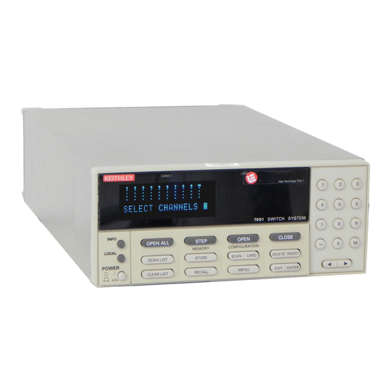
3.2.2 Rear panel figuration information that should be considered before operating the instrument. The rear panel of the Model 7001 is shown in Figure 3- Front panel operation: Demonstrates basic front 2. This figure also includes important abbreviated panel operation through the use of simple exam- information that should be reviewed before operating ples. - Page 27 Channel List. again (or EXIT) to RECALL DELETE cancel message. Restores 7001 to a channel Delete selected entry from LOCAL pattern stored at a specified Channel List or Scan List. Cancels remote, restores memory location.
- Page 28 Micro 8-pin DIN connector. Port using three-wire power cord. consists of four TTL output lines and one TTL input line (one common line). Figure 3-2 Model 7001 rear panel Artisan Scientific - Quality Instrumentation ... Guaranteed | (888) 88-SOURCE | www.artisan-scientific.com...
-
Page 29: Channel Status Display
Getting Started 3.2.3 Channel status display is Row 1, the second row from the top is Row 2, the next row is Row 3, and the bottom row is Row The channel status display provides real-time status of 4. The third integer designates the column of the each available channel for the two slots. - Page 30 Getting Started CARD 1 CARD 2 TALK LSTN Channel 2!36 for Mux = Open Channel Channel 2!4!6 for Matrix = Closed Channel Figure 3-3 Channel status display 1!1!1 1!1!2 1!1!3 1!1!4 1!1!5 1!1!6 1!1!7 1!1!8 1!1!9 1!1!10 1!2!1 1!2!2 1!2!3 1!2!4 1!2!5 1!2!6...
- Page 31 Getting Started 1!10 1!11 1!12 1!13 1!14 1!15 1!16 1!17 1!18 1!19 1!20 1!30 1!21 1!22 1!23 1!24 1!25 1!26 1!27 1!28 1!29 1!35 1!36 1!37 1!38 1!39 1!40 1!31 1!32 1!33 1!34 A. Slot 1 (Card 1) 2!10 2!11 2!12 2!13 2!14...
-
Page 32: Operation Demo
Step 1 of the following procedure will RESET the Mod- figuration procedure in paragraph 3.3.1 has been per- el 7001 to a default scan configuration that is required formed. This initialization will assign the 40-channel for the demonstration procedures (paragraphs 3.3.2 multiplexer simulator to Slot 2 for the following oper- and 3.3.3). -
Page 33: Scan Channels
A. Press “2” and then “1” to enter Channel 1 into NOTE the Channel List. The “2” selects slot 2. The Model 7001 must be in the Scan List display mode (“SCAN CHAN- SELECT CHANNELS 2!1 NELS” prompt displayed). The SCAN LIST key toggles the channel status B. - Page 34 (Channel 1). 6. Press EXIT twice to exit from the CONFIGURE SCAN menu and return to the channel status dis- 1. Press STEP to take the Model 7001 out of the idle play. state. The ARM indicator will turn on.
-
Page 35: Overview Of Scan Process
The front panel ARM indicator is off when the instrument is in the idle state. 10. When finished, press OPEN ALL. When the Model 7001 is taken out of the idle state by Overview of scan process pressing STEP (or sending the :INIT or :INIT:CONT ON command over the IEEE-488 bus), the ARM indica- tor turns on and operation proceeds into the arm layer. -
Page 36: Initial Configuration
(1 to 9999) or for an infinite number of scans. Instrument operation can be performed without any switching cards installed in the Model 7001 by using After the instrument leaves the scan layer, operation the switching card simulators. By selecting the appro- proceeds into the channel layer. -
Page 37: Installing Switching Cards
3.5.3 Card type TYPE #-OF-POLES CARD-PAIR DELAY READ-I/O-CARD In order for the Model 7001 to operate properly, it must know what type of card is installed in each of its two NOTE slots. If a Model 701X series card (such as the Model... -
Page 38: Front Panel Operation
The above message indicates that, when EN- TERed (Step 6), slot 1 will be configured to op- One of the basic functions of the Model 7001 is to sim- erate as a 40-channel switching card. ply close and open one or more specified channels. The following example will demonstrate this operation. - Page 39 Getting Started Note: The following procedure assumes that Slot 2 is SELECT CHANNELS configured for a matrix. If using slot 1 for a matrix, If there is Channel List currently displayed, press modify (A) of steps 1 and 2 by pressing “1” instead of CLEAR LIST to cancel it.
-
Page 40: Scan Operation Example
Step 1. RESET the Model 7001. To close channel 1!8, position the cursor at the end of By performing RESET, the Model 7001 will set itself to the channel list and press “1”, “8” and then CLOSE. default conditions that are typically used to control a The channel list will now look like this: scan. - Page 41 When finished, press OPEN ALL to (Row 1 Column 1, Row 2 Column 2, Row 2 Column 3, place the Model 7001 in the idle state. Row 2 Column 4, and Row 2 Column 5 for slot 2) as fol-...
- Page 42 1. Press SCAN CONFIGURATION to display the fol- Step 5. Configure scan layer of scan. lowing menu: When the Model 7001 was RESET (Step 1), the scan lay- er was reset to IMMEDIATE scan spacing, which is ap- CONFIGURE SCAN propriate for this example.
-
Page 43: Ieee-488.2 And Scpi Basics
At the conclusion of the third scan, the Model 7001 will return to the idle state (ARM indicator will turn off). Note however that the last channel in the scan list remains closed. -
Page 44: Bus Connections
For example, the :TRIGger:SOURce? query command is used to request the currently selected control source. After the query command is sent and the Model 7001 is addressed to talk, a message identifying the selected control source will be sent to the computer. -
Page 45: Syntax Rules
The following information explains some of the pro- gramming syntax for the Model 7001. For more com- plete information see Programming Syntax which is Note that there must be a space between the command located just after the tab labled “SCPI Command Sub-... - Page 46 Getting Started :system:preset :ARM:LAYER2:SOURCE MANUAL :ARM:LAY2:SOUR MAN You can send ... :arm:layer2:source manual :arm:lay2:sour man :system:error?;preset :Arm:Lay2:Sour Man :ArM:LaY2:SouR MaN When the above message is sent, the first command Parameters word is recognized as the root command. When the path pointer sees the colon (:) after the semicolon (;), it As previously mentioned, a parameter is separated resets to the root and starts over.
-
Page 47: Programming Examples
STEP key will scan the next channel in the The following programming examples are written in scan list. Hewlett-Packard BASIC 4.0 programming language. The programs assume that the Model 7001 is set to pri- mary address 7. Programming example #3 bus trigger controlled scan Programming example #1 ... - Page 48 25 OUTPUT 707; “:trig:sour tim” 40 END 26 OUTPUT 707; “:trig:tim 0.5” 30 OUTPUT 707; “:init” Line 10 Return 7001 to :SYSTem:PRESet default con- 40 END figuration (scan count = infinite, channel count = 10 channels, channel control source = Line 10 Return 7001 to :SYSTem:PRESet default con- manual).
- Page 49 Getting Started 3-24 Artisan Scientific - Quality Instrumentation ... Guaranteed | (888) 88-SOURCE | www.artisan-scientific.com...
-
Page 50: Front Panel Operation
Power-up procedure Analog backplane: Explains how two Model The Model 7001 can be operated from line voltages 701X series switching cards may be internally from 100-240VAC at line frequencies of 50 or 60Hz. connected together through the analog back- plane of the Model 7001. -
Page 51: Power Switch
Power-up sequence user using the Card Configuration menu (see para- graph 4.7). On power-up, the mainframe checks its On power-up, the Model 7001 will go through the fol- memory and displays the model number last en- lowing sequence: tered by the user. For example: 1. -
Page 52: Display
The display of the Model 7001 (see Figure 4-1) is prima- At the top of the display are annunciators to indicate rily used to display channel status along with the en- various states of operation. -
Page 53: Channel Status Display
Front Panel Operation 4.3.1 Channel status display CARD 1 The channel status display provides real-time status (open or closed) of each available channel for the two slots; Card 1 and Card 2. Only available channels are displayed. A single “dot” indicates that the available channel is open. -
Page 54: Information And Error Messages
“Invalid Character” (EE) will generate an SRQ (see Section 5). -102 “Syntax Error” (EE REM Turns on to indicate that the Model 7001 is in -103 “Invalid Separator” (EE) remote when used over the IEEE-488 bus. The Model -104 “Data Type Error”... -
Page 55: Analog Backplane
“Expression Error” (EE) be connected to the analog backplane of the Model -281 “Cannot create program” (EE) 7001. The Model 7013 Relay Switch Card is made up of -282 “Illegal program name” (EE) 20 individual IN/OUT relay channels. Each channel is -284 “Program currently running”... - Page 56 H = High Note : Rows correspond to matrix L = Low cards and banks correspond G = Guard to multiplexer cards. Figure 4-4 Model 7001 analog backplane 7001 Matrix Row Analog (1 of 4) Backplane Jumpers H = High...
-
Page 57: Mainframe Programming
The following paragraphs provides detailed informa- CHANNEL assignment for the mainframe. The slot tion on programming the Model 7001 from the front and card channel are separated by an exclamation panel to close channels and perform a scan. - Page 58 CHANNEL 2!3!6 = Slot 2, Row 3, Column 6 as shown in Figure 4-3B. When programming the Mod- el 7001, you need to designate the slot in which the card is installed. Thus, combining the slot number with the All mainframe channel assignments for matrix cards crosspoint coordinates (row/column) provides the are shown in Figure 4-7.
-
Page 59: Channel List And Scan List
The following examples demonstrate how the Scan List is lost: The Model 7001 can perform two basic operations; it can close and open a list of channels, and it can scan 1. Assume the Scan List includes channel 1!21 and through a list of channels. - Page 60 “-” key on the keypad to put in the hyphen, and then key-in the last channel. The following exam- ple shows proper format: NOTE The Model 7001 can store up to 100 SELECT CHANNELS 1!1-1!10, M1, channel patterns in memory locations SCAN CHANNELS 1!1-1!10, M1, M1 through M100.
-
Page 61: Closing And Opening Channels
A. Position the cursor at the desired location in the list. The channel will be inserted between the One of the basic capabilities of the Model 7001 is to selected channel entry and the channel entry close (or open) one or more channels specified by the before it. -
Page 62: Scanning Channels
Step 1. Place instrument in channel list display state. If the Model 7001 is not in the channel list display state, Scan process (Trigger Model) press EXIT and/or SCAN LIST until the following... - Page 63 Front Panel Operation OPEN Idle Idle STEP Another Arm Count Arm Trigger Control = Source (Source Bypass Enabled) Output Trigger Arm Event Spacing Arm Layer Detection Manual Source Immediate Bypass GPIB Enabled External Triglink Hold Scan Trigger Control = Source Another Number of Scans (Source Bypass Enabled)
- Page 64 Front Panel Operation Arm layer TRIGGER LINK output line. For all other arm spacing selections, the output trigger pulse will be available at the CHANNEL READY connector. The output trigger NOTE for this layer is disabled when the Source Bypass is dis- abled (Arm Trigger Control set to Acceptor).
- Page 65 Front Panel Operation After leaving the scan layer, operation proceeds into the CHANNEL READY connector. For TrigLink chan- the channel layer. nel spacing, the Output Trigger functions as follows: 1. If the asynchronous Trigger Link mode is selected, Channel layer the TTL Output Trigger pulse will be available on the programmed Trigger Link output line.
- Page 66 Before configuring a scan, you should place the Model B. EXTERNAL With this selection, external 7001 in the idle state by pressing OPEN ALL. This will triggers control channel spacing. Each trigger stop any scan that is currently in process, open all applied to the rear panel EXTERNAL TRIG- channels, and place the Model 7001 in the idle state.
- Page 67 *TRG) control scan spacing. A bus trigger re- or *TRG) control arm spacing. A bus trigger re- ceived by the Model 7001 will allow operation ceived by the Model 7001 will allow operation to proceed to the channel layer.
- Page 68 Step 1 of this procedure placed the Model 7001 in the idle state. In this idle state, a scan cannot be performed. ARM SPACING = IMMEDIATE The Model 7001 is taken out of the idle state by press- SCAN SPACING = IMMEDIATE ing the STEP key.
-
Page 69: Storing Channel Patterns (Store And Recall)
OPEN ALL Use to stop a scan, open all channels, and place the Model 7001 in the scan idle state. STEP Use to take the Model 7001 out of the idle state; Example 4: and also, use to manually step through a scan. - Page 70 RECALL. The open/close channel pat- Step 2. If there are any undesired channels currently tern will be displayed on the Model 7001 indicating the actual state of each channel. The other way is to specify closed, press OPEN ALL to open them.
-
Page 71: Menu
You can exit from the Recall mode Various instrument operations to configure the Model without recalling the channel pattern 7001 are performed using the front panel MENU. The by pressing EXIT. The instrument will MENU structure is shown and summarized in Table 4- return to the channel list display state. - Page 72 Description SAVESETUP Setup Menu: SAVE Save setup at a memory location (up to 10). RESTORE Return 7001 to setup stored at a memory location. PWRON Power-on Menu: FACTORY DEFAULT Power-on to factory default setup conditions. USER SETUP Power-on to setup stored at a memory location.
-
Page 73: Savesetup
Front Panel Operation 4.6.1 SAVESETUP 1. To restore the instrument to the setup conditions stored at the displayed memory location, press The SAVESETUP menu is used for the following oper- ENTER. The instrument will return to the SETUP ations: MENU. 2. -
Page 74: Gpib
Front Panel Operation Table 4-3 Default conditions Item Factory default RESET Channel status All open All open Channel list Cleared No change Scan list No change No change GPIB address No change No change Digital I/O output level High High Language No change No change... -
Page 75: Digital-I/O
Front Panel Operation information on the status byte. To select STATUS, place mined by the polarity, which is controlled by the next the cursor on STATUS and press ENTER. If for exam- menu item (OUTPUT-POLARITY). To select OUTPUT- ple, all bits of the status byte are reset to zero, it will be STATUS, place the cursor on OUTPUT-STATUS and displayed as follows: press ENTER. -
Page 76: Test
The GENERAL MENU is used for the following oper- ations: The TEST menu is to be used as a diagnostic tool to iso- late problems with the Model 7001. Refer to Section 7 • Serial # of the Model 7001. -
Page 77: Card Config
Front Panel Operation where; AXX is the software revision of the main CPU. Cursor position indicates the current state of Break-Be- AYY is the software revision of the display fore-Make. CPU. When finished, press ENTER or EXIT to return to the Place the cursor on the desired state and press ENTER. -
Page 78: Type
The TYPE menu selection displays an assignment mes- cursor key. sage for each slot. These messages were determined by the Model 7001 mainframe during its power-up se- 5. A numeric parameter is keyed in by placing the quence and is explained in paragraph 4.2.3. In general,... - Page 79 Front Panel Operation Table 4-5 TYPE assignments Assignment message Interpretation* SLOT-1 CARD: 701X** 701X series card installed in slot 1. SLOT-1 CARD: NONE No card installed in slot 1, or slot 1 is not assigned. SLOT-1 CARD: 7YYY*** Non-701X series model number assigned to slot 1 by the user. The card may or may not be installed in the slot.
-
Page 80: Of-Poles
Front Panel Operation 3. With the correct slot assignment displayed, press Switch cards that have an additional pole mode capa- ENTER. The display will return to the SET CARD bility are summarized as follows: TYPE menu. Pole Mode Card 1-Pole 2-Pole 4-Pole SLOT-2 ... -
Page 81: Card-Pair
The CARD-PAIR is used to enable (on) or disable (off) Perform the following steps to set the delay: the CARD-PAIR feature of the Model 7001. CARD- PAIR can be enabled to pair two similar type switching 1. Display the CARD CONFIG MENU (see para- cards that have the same number of channels. -
Page 82: Read-I/O-Card
MENU. 4.7.5 READ-I/O-CARD This menu selection is used to identify if there are any I/O cards installed in the Model 7001. SCAN CONFIG 1. Display the CARD CONFIG MENU (see para- Various operations to configure a scan are performed graph 4.7, General Rule #1). - Page 83 Front Panel Operation Table 4-6 (cont.) CONFIGURE SCAN menu structure Menu item Description SCAN-CONTROL Configure Scan Layer: SCAN-SPACING Select scan spacing: TIMER Use the timer to control scan spacing. EXTERNAL Use external triggers to control scan spacing. GPIB Use bus triggers to control scan spacing. MANUAL Use STEP key to control scan spacing.
-
Page 84: Chan-Control
) to place the cursor TERNAL TRIGGER” BNC connector. In the external on CHAN-CONTROL and press ENTER to access trigger mode, the Model 7001 can be used to trigger an- the following menu: other instrument. After a channel is closed and settled, a trigger pulse is applied to the rear panel “CHANNEL... - Page 85 Manual With this selection, the front panel STEP key 2. To select a trigger input line for the Model 7001, is used to control channel spacing. Each time the STEP place the cursor on the desired line number and key is pressed, the current channel of the scan will press ENTER.
- Page 86 1!4), the user can program a count of 12. With this count value, the instrument will repeat the channel 2. To select a trigger line for the Model 7001, place the scan three times. An advantage of repeating channels...
-
Page 87: Scan Control
SCAN-CONTROL and press ENTER to access used to control scan spacing. A trigger stimulus ap- the following menu: plied to the Model 7001 will pass operation into the channel layer. The external trigger is applied to the rear SCAN CONTROL panel “EXTERNAL TRIGGER”... - Page 88 (GET or *TRG) is received by the Model 7001. See Section 5 for detailed information To select a trigger input line for the Model 7001, place on bus triggers. the cursor on the desired line number and press EN- TER.
-
Page 89: Arm Control
Designate the number of times the scanner is to be mines the number of scans to perform. You can pro- armed (ARM COUNT) gram the Model 7001 to perform from 1 to 9999 scans. • Enable or disable the Source Bypass. - Page 90 Front Panel Operation ceived by the Model 7001. See Section 5 for detailed in- To select a trigger input line for the Model 7001, place formation on bus triggers. the cursor on the desired line number and press EN- TER. The following message will be displayed:...
-
Page 91: Channel Restrictions
4.8.4 Channel restrictions is assigned to a channel list, only the lowest num- The Model 7001 can be programmed for the following bered channel in the lowest numbered slot will channel restrictions: close when CLOSE is pressed. For example, as- sume the following channel list is defined:... -
Page 92: Digital I/O Port
Channel pattern is cleared (lost)/ See para- graphs 4.5.2 and 4.5.5 for more information. Digital I/O port The Model 7001’s Digital I/O port is an 8-pin micro- Perform the following steps to define the restricted DIN socket (J1007) located on the rear panel. Figure channels: 4-9 shows a simplified schematic containing pin des-... -
Page 93: Controlling Digital Circuitry
Front Panel Operation The Model 7001’s Digital I/O port can be used to con- 4.9.1 Controlling digital circuitry trol external circuitry. The port provides four output Each of the four digital, open-collector outputs (con- lines and one input line. Each open-collector output... - Page 94 Low-power TTL, or CMOS inputs: Model 7001’s collector outputs to turn on externally powered devices, set the correspinding digital output 1. Connect the Model 7001 digital outputs to the logic line parameters as follows (set through the MAIN inputs. MENU > DIGITAL-I/O > OUTPUT-STATUS and 2.
-
Page 95: Digital Input Channel
Digital input channel 4.9.3 I/O port connections The Model 7001 has one digital input channel that is The DIGITAL I/O port is located on the rear panel as used to read a TTL input level. A TTL high on the input shown in Figure 4-11. - Page 96 Front Panel Operation By hard-wiring an external circuit to an 8-pin micro CAUTION DIN female receptacle (see rear panel; Keithley Model Trigger Link and the Digital I/O port 8501), you can use one complete Trigger Link cable for use the same type of connector. To the digital I/O connections.
-
Page 97: External Triggering
Digital I/O connections using trigger link cable 4.10 External triggering Triggers on Leading Edge The Model 7001 has BNC connectors on the rear panel (see Figure 4-13) associated with external triggering. TTL High The EXTERNAL TRIGGER input jack allows the Mod-... -
Page 98: Channel Ready
Number of Channels = Use Scan list Length* Channel Trigger Control = Source* The Model 7001 can also output a trigger while in the scan and/or arm layers of operation. Figure 4-9 shows * Indicates that the setting is the RESET (and factory) default where these triggers occur in the trigger model. - Page 99 #2. When the measurement is completed, a trigger is the Model 196 to trigger a measurement of DUT #1. Af- sent to the Model 7001 to close the next channel. After ter the Model 196 completes the measurement, it will...
-
Page 100: Trigger Link
In general, Trigger Link input triggers to the Model When using Trigger Link in these layers, you must also 7001 are used to control scan operation. In order for the select input and output lines as you did in the channel Model 7001 to respond to Trigger Link compatible trig- layer. - Page 101 Asynchronous Trigger Link example #1 The Trigger Link connections for this test system are shown in Figure 4-20. Trigger Link of the Model 7001 is In a typical test system, you may want to close a chan- connected to Trigger Link of the meter. Notice that only nel and then measure the DUT connected to that chan- one Trigger Link cable is needed.
- Page 102 Front Panel Operation For this example, the Model 7001 and the meter are diately as soon as the scanner is taken out of the idle configured as follows: state by pressing the STEP key (assuming the meter is also out of the idle state).
- Page 103 Front Panel Operation 7001 Meter Step 2. Press STEP Step 1. Press TRIG Idle Idle Bypass Wait for Wait for Trigger Link Trigger Link Trigger Trigger Scan Make Channel Measurement Trigger Trigger Output Output Trigger Trigger Make Scanned Measurements Channels...
- Page 104 With this adapter, the Model 196 could be grammed for External Triggering and the Model 230 is substituted for the meter with Trigger Link in the pre- set to source the first voltage level. The Model 7001 is vious example (Asynchronous Trigger Link Example configured as follows: #1).
- Page 105 OUTPUT COM OUT 196 DMM Voltage Source Card 1 7011 MUX Card Figure 4-23 DUT test system (asynchronous example #2) Trigger Link Cable (8501) 7001 Switch System Trigger Link Trigger Link 8502 Adapter BNC to BNC Cables (4) (7501) Voltage...
- Page 106 A where it will wait for an input trig- condition. ger. Note that Bypass is no longer in effect. To run the test, simple press STEP on the Model 7001. The trigger pulse from the Model 7001 triggers The following explanation on operation is referenced the Model 230 to output the next programmed voltage to the operation model shown in Figure 4-25.
- Page 107 Front Panel Operation 7001 Press STEP Idle Bypass Wait for Trigger Link Trigger Bypass Wait for Trigger Link Trigger Scan Channel Trigger Trigger Trigger 196 Output to make Trigger Measurement 7001 and Output Trigger Scanned Channels Trigger 230 Trigger Trigger...
-
Page 108: Semi-Synchronous Operation
Model 7001s are in the process of closing a channel, they will hold the trigger line low. Ten milliseconds af- ter switch closure, the first Model 7001 will release the trigger line. However, the second Model 7001 will con- Trigger on... - Page 109 STEP on the Mod- Number of Scans = 1 el 7001. The following explanation on operation is ref- Scan Trigger Control = Acceptor* erenced to the operation model shown in Figure 4-29.
- Page 110 A waiting for a trigger. When the trigger line was chart where it is waiting for a Trigger Link trigger. Note pulled low by the Model 7001, the leading negative-go- that since both the arm layer and scan layer are pro-...
- Page 111 Front Panel Operation 7001 Meter Step 2. Press STEP Step 1. Press TRIG Idle Idle Bypass Wait for Trigger Link Wait for Trigger Trigger Link Trigger Scan Make Channel Measurement Pull Trigger Release Line Low Trigger Line Make Scanned Measurements...
-
Page 112: Dut Test System Using Two Switching Mainframes
Front Panel Operation 4.12 DUT test system using two switch- a total of forty 2-pole channels. This test system (shown in Figure 4-30) will scan and measure the forty 2-pole channels ing mainframes twice (two scans). The Trigger Link connections for this test system are shown in Figure 4-31. -
Page 113: Dmm Settings
Front Panel Operation Digital Multimeter WARNING: WARNING: NO INTERNAL OPERATOR SERVICABLE PARTS,SERVICE BY QUALIFIED PERSONNEL ONLY. NO INTERNAL OPERATOR SERVICABLE PARTS,SERVICE BY QUALIFIED PERSONNEL ONLY. RS232 EXT TRIG FUSE LINE 250mAT 100 VAC (SB) 120 VAC 220 VAC 125mAT (SB) 240 VAC CAUTION: CAUTION:... -
Page 114: Switching Mainframe A Settings (7001)
Front Panel Operation 4.12.2 Switching mainframe A settings (7001) Scan List = 1!1-1!10, 2!1-2!10, M1, NOTE M1 is a “dummy” channel configured to open all channels. This lets the last channel in a mainframe open before closing the first channel in the other mainframe. -
Page 115: Switching Mainframe B Settings (7001)
Front Panel Operation 4.12.3 Switching mainframe B settings (7001) Scan List = 1!1-1!10, 2!1-2!10, M1, NOTE M1 is a “dummy” channel configured to open all channels. This lets the last channel in a mainframe open before closing the first channel in the other mainframe. -
Page 116: Operation Details
Front Panel Operation 4.12.5 Operation details operation then loops up to point A1 (A for Mainframe A) where it waits for an input trigger. The detailed step-by-step testing process is explained as fol- 5. After the DMM receives the trigger, it performs a mea- lows using the flowchart in Figure 4-32. - Page 117 Front Panel Operation Digital Multimeter Wait for Make Output Trigger Measurement Trigger Switching Mainframe A Switching Mainframe B Press STEP to Start Scan Press STEP to Start Scan Idle Idle Arm Layer Wait for Layer Trigger Scan Wait for Layer Trigger Scan Layer Wait for...
- Page 118 Front Panel Operation Switching Mainframe A Switching Mainframe B LAYER LAYER In 5 In 4 Trig Trig Link Link Out 6 Out 3 Source Acceptor SCAN SCAN LAYER LAYER In 3 In 4 Trig Trig Link Link Out 4 Out 3 Source Source CHAN...
- Page 119 Front Panel Operation 4-70 Artisan Scientific - Quality Instrumentation ... Guaranteed | (888) 88-SOURCE | www.artisan-scientific.com...
-
Page 120: Ieee-488 Reference
5.10 Common commands: Covers the IEEE-488.2 com- mon commands used by the Model 7001. This section contains reference information on programming the Model 7001 over the IEEE-488 bus and is organized as 5.11 SCPI command subsystems: Covers the SCPI com- follows: mands used by the Model 7001. -
Page 121: Ieee-488 Bus Connections
Instrument turned by the instruments. IEEE-488 bus connections The Model 7001 can be connected to the IEEE-488 bus through a cable equipped with standard IEEE-488 connec- tors, an example is shown in Figure 5-1. The connector can be stacked to allow a number parallel connections to one in- strument. -
Page 122: Figure 5-4 Contact Assignments
IEEE-488 Reference Table 5-1 IEEE contact designations IEEE-488 Contact IEEE-488 number designation Type DIO1 Data DIO2 Data DIO3 Data Figure 5-3 IEEE-488 connector location DIO4 Data EOI (24)* Management Handshake Custom cables may be constructed by using the information NRFD Handshake in Table 5-1 and Figure 5-4. -
Page 123: Primary Address Selection
IEEE-488 Reference Primary address selection Controller programming The Model 7001 must receive a listen command before re- The programming instructions covered in this section use ex- sponding to addressed commands. Similarly, the unit must amples written with Hewlett-Packard BASIC version 4.0. -
Page 124: Error And Status Messages
Send remote enable. REMOTE 7 Cancel remote enable. LOCAL 7 LSTN This indicator is on when the Model 7001 is in the Serial poll device 07. SPOLL (707) listener active state, which is activated by addressing the in- Send local lockout. - Page 125 IEEE-488 Reference Figure 5-5 Model 7001 status register structure Artisan Scientific - Quality Instrumentation ... Guaranteed | (888) 88-SOURCE | www.artisan-scientific.com...
-
Page 126: Standard Event Status
IEEE-488 Reference 5.6.1 Standard event status In general, the occurrence of a standard event sets the appro- priate bit in the Standard Event Status Register. This register The reporting of standard events is controlled by two 16-bit can be read at any time to determine which, if any, standard registers;... -
Page 127: Operation Event Status
IEEE-488 Reference Standard Event Status Register — This is a latched read corresponding set bit in the Standard Event Status Enable only register that is used to record the occurrence of standard Register. The logic “1” output of the AND gate is applied to events. - Page 128 Transition Filter is discussed next. rent operating conditions of the Model 7001. For example, when the instrument is in idle, bit B10 (Idle) of this register will be set. When the instrument leaves the idle state, bit B10 Operation Transition Filter —...
- Page 129 IEEE-488 Reference The filter can be programmed for positive transitions (PTR), Reading this register using the above SCPI command clears negative transitions (NTR) or both. When an event bit is pro- the register. The following list summarizes all operations that grammed for a positive transition, the event bit in the Opera- will clear the Operation Event Register: tion Event Register will set when the corresponding bit in the...
-
Page 130: Arm Event Status
IEEE-488 Reference Reading this register using the above SCPI command does Arm Event Register, and the Arm Event Enable Register. not clear the register. The following list summarizes opera- Figure 5-8 shows how these registers are structured. Notice tions that will clear the Operation Event Enable Register: in Figure 5-5 that bit B1 (In An Arm Layer) of the Arm Con- dition Register is controlled by the sequence event register 1. - Page 131 IEEE-488 Reference Arm Condition Register — This is a real-time 16-bit read- 1. Cycling power. only register that constantly updates to reflect the ORed sum- 2. Sending the :STATus:PRESet command. mary of the sequence event register set. In general, if bit B1 3.
-
Page 132: Sequence Event Status
The transition filter registers can be set or cleared by using the following SCPI commands: Two bits of this register set are used by the Model 7001 to re- :STATus:OPERation:ARM:SEQuence:PTRansition <NRf> port sequence events. Bit B1 (In Arm Layer 1) is set when in- :STATus:OPERation:ARM:SEQuence:NTRansition <NRf>... -
Page 133: Figure 5-9 Sequence Event Status
IEEE-488 Reference Always Lay2 Lay1 Zero Sequence Event Condition Register (B15) (B2) (B1) (B14 - B3) (B0) Lay2 Lay1 Sequence Event Transition Filter (B15) (B2) (B1) (B0) (B14 - B3) Lay2 Lay1 Sequence Event Status Register (B15) (B2) (B1) (B14 - B3) (B0) &... -
Page 134: Trigger Event Status
(In Trigger Layer). In general, Bit B1 sets when the instru- ment is in (or has exited) the measure layer of operation. An explanation of the Model 7001 operation process is provided A bit in the Sequence Event Register is masked when the in paragraph 5.7. -
Page 135: Figure 5-10 Trigger Event Status
IEEE-488 Reference Always Seq1 Zero Trigger Event Condition Register (B15) (B14 - B2) (B1) (B0) Seq1 Trigger Event Transition Filter (B15) (B1) (B0) (B14 - B2) Seq1 Trigger Event Status Register (B15) (B14 - B2) (B1) (B0) & & To Waiting for Trigger Bit (Trig) of Operation Event Condition Register Seq1... - Page 136 IEEE-488 Reference The transition filter register can be read at any time by using Trigger Event Enable Register — This register is pro- the following SCPI query commands: grammed by the user and serves as a mask for the Trigger Event Register.
-
Page 137: Questionable Event Status
An error message from the Error Queue is read by sending either of the following SCPI query commands and then ad- 5.6.7 Queues dressing the Model 7001 to talk: The Model 7001 uses two queues; the Output Queue and the :SYSTem:ERRor? Error/Status Queue. The queues are first-in first-out (FIFO) :STATus:QUEue? registers. - Page 138 IEEE-488 Reference Status Summary Messages * STB ? Status Byte Register Serial Poll (B15 - B8) (B7) (B6) (B5) (B4) (B3) (B2) (B1) (B0) & & & & & * SRE Service Request Enable Register (B15 - B8) (B7) (B6) (B5) (B4) (B3)
- Page 139 Status Byte Register will set bit B6. vice the request. Typically, service requests (SRQs) are man- aged by the serial poll sequence of the Model 7001. If an SRQ does not occur, bit B6 (RQS) of the Status Byte Regis-...
-
Page 140: Trigger Model (Ieee-488 Operation)
80 IF BIT (S,6) THEN Service ! Go to Service (line The following information describes the operation process of 200). the Model 7001 over the IEEE-488 bus. The flowchart in 90 END Figure 5-12, which summarizes operation over the bus, is 200 SUB Service called the Trigger Model. - Page 141 IEEE-488 Reference :ABORt *RST :SYST:PRES :INIT :INIT:CONT ON Idle :INIT:CONT ON Initiate :ARM:TCONfigure:DIRection SOURce (Source Bypass Enabled) Another Arm Layer 1 :ARM:COUNt <n> :ARM:IMMediate :ARM:SIGNal (Arm Layer) Output Arm Event Trigger Source Detection :ARM:SOURce IMMediate :ARM:SOURce MANual Source :ARM:SOURce BUS Bypass :ARM:SOURce EXTernal Enabled...
- Page 142 With the Manual control source selected (:ARM :SOURce MANual), the instrument will wait until the front panel STEP key is pressed. Note that the Model 7001 must be tak- After all other instrument operations have been completed, en out of remote (press LOCAL key or send LOCAL 707 the instrument can be returned to Arm Layer 1 by program- over bus) before it will respond to the STEP key.
- Page 143 STEP key is pressed. Note that the for a programmed scan event to occur (or when the Hold Model 7001 must be taken out of remote (press LOCAL key control source is selected). or send LOCAL 707 over bus) before it will respond to the 3.
- Page 144 :SOURce MANual), the instrument will wait until the front trol source is selected). panel STEP key is pressed. Note that the Model 7001 must 3. Each time the :TRIGger:SIGNal command is sent, oper- be taken out of remote (press LOCAL key or send LOCAL ation will loop around the channel control source.
-
Page 145: General Bus Commands
07, and check to see that the bus connections are properly made. The remote enable command is sent to the Model 7001 by the controller to set up the instrument for remote operation. Generally, the instrument should be placed in the remote Note that all front panel controls except for LOCAL (and, of mode before you attempt to program it over the bus. -
Page 146: Ifc (Interface Clear)
LOCAL key. The IFC command is sent by the controller to place the Mod- el 7001 in the local, talker, and listener idle states. The unit responds to the IFC command by cancelling front panel... -
Page 147: Sdc (Selective Device Clear)
The Model polling sequence. After the second statement is executed, the 7001 will react to this trigger if it is the programmed control decimal value of the serial poll byte is displayed on the con- source. -
Page 148: Programming Syntax
IEEE-488 Reference Programming syntax The following programming syntax information covers both common commands and SCPI commands. For information not covered here, refer to the documentation for the IEEE-488.2 standard and SCPI. Command words One or more command words make up the program message that is sent to the computer to per- form one or more operations. - Page 149 Numeric representation format: This parameter is a number that can be expressed as an integer (e.g., 8), a real number (e.g., 23.6) or an ex- ponent (2.3E6) When necessary, the Model 7001 will round real and exponential parameter values to an integer. Example: :SAV 36 Save setup in memory location 36.
- Page 150 IEEE-488 Reference The <b> indicates that a Boolean type parameter is required. Thus, to set digital input line #2 true, you must send the command with the ON or 1 parameter as follows: :SOURce:TTL2 ON or :SOURce:TTL2 1 2. Query commands: This type of command requests (queries) the currently programmed status.
- Page 151 IEEE-488 Reference :open = :open :line = :line B. The following rules apply to command words that exceed four letters: a. If the fourth letter of the command word is a vowel, delete it and all the letters after it. Examples: :immediate = :imm :timer...
- Page 152 IEEE-488 Reference as command paths. The following command paths are contained in the :STATus subsystem and are used to help explain how command words are structured to formulate program messages. :STATus Path (Root) :OPERation Path :PTRansition <NRf> Command and parameter :NTRansition <NRf>...
- Page 153 IEEE-488 Reference 3. Command path rules: A. Each new program message must begin with the root command, unless it is optional (e.g., [:SENSe]). If the root is optional, simply treat a command word on the next level as the root. B.
- Page 154 (see Multiple command messages), the multiple response message for all the queries will be sent to the computer when the Model 7001 is addressed to talk. The respons- es are sent in the order that the query commands were sent and will be separated by semi- colons (;).
- Page 155 The message exchange protocol can be summarized by the two following rules: Rule 1. You must always tell the Model 7001 what to send to the computer. The following two steps must always be performed, in this order, to send information from the instrument to the computer: 1.
-
Page 156: Common Commands
Common commands are device commands that are common to all devices on the bus. These commands are designated and defined by the IEEE-488.2 standard. Table 5-4 summarizes the common commands used by the Model 7001 and are presented in al- phabetical order. The following detailed descriptions include programming examples using HP BASIC 4.0. - Page 157 This command issues a bus trigger which has the same 5.10.15 effect as group execute trigger (GET) command. *TST? Self-test query When this query is sent, the Model 7001 will perform a 5.10.16 checksum test on ROM and return the results. *WAI Wait-to-continue Wait until all previous commands are executed.
-
Page 158: Cls Clear Status
To clear status registers and error queue. Purpose *CLS Format Description The *CLS command is used to clear (reset to 0) the bits of the following registers in the Model 7001: Standard Event Status Register Operation Event Register Questionable Event Register Error Queue Trigger Event Register... -
Page 159: Ese Event Status Enable
IEEE-488 Reference *ESE event status enable 5.10.2 To set the contents of the Standard Event Status Enable Register. Purpose *ESE <NRf> Format Parameters <NRf> = 0 Clear (reset) register Set OPC (B0) of enable register Set QYE (B2) of enable register Set DDE (B3) of enable register = 16 Set EXE (B4) of enable register... - Page 160 IEEE-488 Reference where; CME (bit B5) = Decimal QYE (bit B2) = Decimal parameter = If a command error (CME) occurs, bit B5 of the Standard Event Status Register will set. If a query error (QYE) occurs, bit B2 of the Standard Event Status Register will set. Since both of these events are unmasked (enabled), the occurrence of any one of them will cause the ESB bit in the Status Byte Register to set.
-
Page 161: Ese? Event Status Enable Query
Register. The binary equivalent of the decimal value determines which bits in the register are set. When the *ESE? query command is sent, the decimal value is placed in the Output Queue. When the Model 7001 is addressed to talk, the value is sent from the Output Queue to the com- puter. -
Page 162: Esr? Event Status Register Query
Bit B0, Operation Complete (OPC) Set bit indicates that all pending selected device oper- ations are completed and the Model 7001 is ready to accept new commands. This bit will only set in response to the *OPC? query command (see paragraph 5.10.7). - Page 163 IEEE-488.2 command that is not implemented. 3. The instrument received a Group Execute Trigger (GET) inside a program message. Bit B6, User Request (URQ) Set bit indicates that the LOCAL key on the Model 7001 front panel was pressed.
-
Page 164: Idn? Identification Query
Description The *IDN? query command places the identification code of the Model 7001 in the Output Queue. When the Model 7001 is addressed to talk, the identification code will be sent to the computer. The identification code includes the manufacturer, model number, serial number, and firmware revision levels, and is sent in the following format: KEITHLEY INSTRUMENTS INC., MODEL 7001, wwwwwww, xxxxx,/yyyyy/zzzzz... -
Page 165: Opc Operation Complete
When used with the :INITiate or :INITiate:CONTinuous ON command, the OPC bit of the Stan- dard Event Status Register will not set until the Model 7001 goes back into the idle state. The initiate operations are not considered finished until the instrument goes into the idle state. - Page 166 Enables automatic scan-list-length for channel count. Line 50 Sets a 0.5 second delay between each channel. Line 60 Starts the scan (takes 7001 out of idle state). Line 70 Set OPC bit after the scan ends. Line 80 Request value of Standard Event Status Register.
-
Page 167: Opc? Operation Complete Query
When used with the :INITiate or :INITiate:CONTinuous ON command, an ASCII “1” will not be sent to the Output Queue and the MAV bit will not set until the Model 7001 goes back into the idle state. The initiate operations are not considered finished until the instrument goes into the idle state. - Page 168 IEEE-488 Reference After *OPC? is executed, additional commands cannot be sent to the Model 7001 until the pend- ing overlapped commands have finished. For example, :INITiate:CONTinuous ON followed by *OPC? will lock up the instrument and will require a device clear (DCL or SDC) before it will accept any more commands.
-
Page 169: Opt? Option Identification Query
The *OPT? query command places the option identification code in the Output Queue. When the Model 7001 is addressed to talk, the code is sent from the Output Queue to the computer. The option identification code indicates the assigned model number for each slot of the main- frame. -
Page 170: Rcl Recall
<NRf> = 0 to 9 Memory location Description The Model 7001 can store up to 10 setup configurations in memory locations 0 to 9. Over the bus, the *SAV command is used to save setup configurations (see paragraph 5.10.11). The *RCL command is used to return the Model 7001 to a setup configuration stored at one of the memory locations. -
Page 171: Rst Reset
*RST Format Description When the *RST command is sent, the Model 7001 performs the following operations: 1. Returns the Model 7001 to the *RST default conditions (see Table 5-5). 2. Cancels all pending commands. 3. Cancels response to any previously received *OPC and *OPC? commands. - Page 172 IEEE-488 Reference Table 5-5 Default conditions Command name *RST value :SYSTem:PRESet value :INITiate :CONTinuous :ARM :SEQuence[1] :LAYer[1] :COUNt :SOURce IMMediate IMMediate :TCONfigure :DIRection ACCeptor ACCeptor :ASYNchronous :ILINe :OLINe :LAYer2 :COUNt INFinite :DELay :SOURce IMMediate IMMediate :TIMer 0.001 0.001 :TCONfigure :DIRection ACCeptor ACCeptor :ASYNchronous...
-
Page 173: Sav Save
Memory location Description The Model 7001 can store up to 10 setup configurations at memory locations 0 to 9 by using the *SAV command. For example, to store the current setup configuration at memory location 6, send the following command:... -
Page 174: Sre Service Request Enable
IEEE-488 Reference *SRE service request enable 5.10.12 To set the contents of the Service Request Enable Register. Purpose *SRE <NRf> Format Parameters <NRf> = 0 Clears enable register Set EAV bit (Bit 2) Set QSB bit (Bit 3) = 16 Set MAV bit (Bit 4) = 32 Set ESB bit (Bit 5) - Page 175 IEEE-488 Reference OUTPUT 707; “*SRE 32” ! Set ESB bit Programming example Bit Position Event ESB MAV QSB EAV Decimal Weighting (2 ) (2 ) (2 ) (2 ) (2 ) Value Value : 1 = Enable Service Request Event 0 = Disable (Mask) Service Request Event Events : OSB = Operation Summary Bit ESB = Event Summary Bit...
-
Page 176: Sre? Service Request Enable Query
Register. The binary equivalent of the decimal value determines which bits in the register are set. When the *SRE? query command is sent, the decimal value is placed in the Output Queue. When the Model 7001 is addressed to talk, the value is sent from the Output Queue to the com- puter. -
Page 177: Stb? Status Byte Query
Model 7001. When the *STB? query command is sent, the decimal value is placed in the Output Queue. When the Model 7001 is addressed to talk, the value is sent from the Output Queue to the com- puter. -
Page 178: Figure 5-16 Status Byte Register
:STATus:OPERation? See paragraph 5.16 for details. Programming OUTPUT 707; “*SRE?” ! Request contents of register example ENTER 707; A$ ! Address 7001 to talk PRINT A$ ! Display value of register Bit Position MSS, Event ESB MAV QSB EAV Decimal Weighting... -
Page 179: Trg Trigger
Format Description The *TRG command is used to issue a GPIB trigger to the Model 7001. It has the same effect as a group execute trigger (GET). The *TRG command is an overlapped command, while GET is not. See *OPC, *OPC? and *WAI for more information. -
Page 180: Tst? Self-Test Query
The *TST? query command is used to perform a checksum test on ROM and place the coded result (0 or 1) in the Output Queue. When the Model 7001 is addressed to talk, the coded result is sent from the Output Queue to the computer. -
Page 181: Wai Wait-To-Continue
See *OPC, *OPC? and *TRG for more information. The :INIT command takes the Model 7001 out of the idle state to enable the scan function. The device operations of the :INIT command are not considered complete until the Model 7001 goes back into the idle state. - Page 182 IEEE-488 Reference Line 70 Wait until scan is finished. Line 80 Close channels 11 through 20. When the above program is run, channels 1 through 10 will be scanned and then, at the end of the scan, channels 11 through 20 will close. Without the *WAI command (Line 70), channels 11 through 20 will close at the same time that the scan starts.
- Page 183 IEEE-488 Reference 5-64 Artisan Scientific - Quality Instrumentation ... Guaranteed | (888) 88-SOURCE | www.artisan-scientific.com...
- Page 184 Model 7001. 5.17 :SYSTem subsystem — Covers miscellaneous commands used to read the software revision level of the Model 7001, read the error queue, and set the power-on setup configuration. 5.18 Trigger subsystem — Covers commands used to scan.
- Page 185 IEEE-488 Reference 5-66 Artisan Scientific - Quality Instrumentation ... Guaranteed | (888) 88-SOURCE | www.artisan-scientific.com...
-
Page 186: Display Subsystem
IEEE-488 Reference :DISPlay subsystem 5.11 The display subsystem controls the display circuitry of the Model 7001 and is summarized in Table 5-6. Table 5-6 DISPlay command summary Command Description :DISPlay [:WINDow[1]] Path to locate message to top display. :TEXT Path to control user text messages. - Page 187 A string message must be enclosed in single quotes or double quotes. Both of the following sting messages are valid: ‘Keithley Model 7001’ or “Keithley Model 7001” An indefinite block message must be the only command in the program message or the last com- mand in the program message.
- Page 188 Description (see previous command) will be shown on the top or bottom portion of the display. When dis- abled, the message will be removed from the display, and the Model 7001 will resume normal operation. A user defined text message remains displayed only as long as the instrument is in remote. Tak- ing the instrument out of remote (by pressing the LOCAL key or sending LOCAL 707), cancels the message and disables the text message mode.
- Page 189 LED Grat- icule. ERROR:ID CODE = +551 Incorrect software revision If this error should occur, contact Keithley to resolve the firmware incom- patibility. Programming 10 OUTPUT 707; “:disp:wind3:grat on; grat?”...
- Page 190 Response message: 1 (on) or 0 (off) This command is used to enable/disable the status message mode for the Model 7001. The status Description message mode is a diagnostic tool that provides real-time messages that relate to the current op- erating state of the instrument.
- Page 191 ENTER 707; A$ PRINT A$ Line 10 Disables the display, and then queries the state of the display. Line 20 Addresses the 7001 to talk. Line 30 Displays (on the CRT) the programmed state of the display (0; off). 5-72...
-
Page 192: Output Subsystem
IEEE-488 Reference :OUTPut subsystem 5.12 The OUTPut subsystem is used to set polarities for the digital output port. Commands in this subsystem are summarized in Table 5-7. Table 5-7 OUTPut command summary Command Description :OUTPut :TTL[1] Path to set polarity of digital output line 1: :LSENse <name>... - Page 193 ENTER 707; A$ PRINT A$ Line 10 Sets the polarity of line #1 to active low. Line 20 Addresses the 7001 to talk. Line 30 Displays the polarity of line #1 (ALOW). 5-74 Artisan Scientific - Quality Instrumentation ... Guaranteed | (888) 88-SOURCE | www.artisan-scientific.com...
-
Page 194: Route] Subsystem
IEEE-488 Reference [:ROUTe] subsystem 5.13 The ROUTe subsystem is used to control signal routing through the switch system and is summarized in Table 5-8. The brackets indicate that :ROUTe is optional and need not be included in the command message. Table 5-8 ROUTe command summary Command... -
Page 195: Close
The :CLOSe? <list> query command is used to determine the state (closed or not closed) of each specified channel. After sending this command and addressing the Model 7001 to talk, the val- ues for the specified channels will be sent to the computer. A value of “1” indicates that the chan- nel is closed, and a “0”... - Page 196 [:ROUTe] subsystem IEEE-488 Reference After addressing the Model 7001 to talk, the following response message will be sent to the computer: 0,1,1,0,0,1,0,0,0,0 Programming This example assumes that all channels are initially open. example OUTPUT 707; “:clos (@ 1!2, 1!3, 1!6); clos? (@ 1!1:1!10)”...
-
Page 197: Open
Channel pattern stored at memory location M36. The :OPEN? <list> query command is used to determine the state (open or not open) of each specified channel. After sending this command and addressing the Model 7001 to talk, the val- 5-78...- |All
-
Page 198: Scan
“0” indicates that the channel is not open (closed). For example, assume channels 2, 3 and 6 are open and the following query command is sent: :open? (@ 1:10) After addressing the Model 7001 to talk, the following response message will be sent to the computer: 0,1,1,0,0,1,0,0,0,0 Programming This example assumes that all channels are closed. - Page 199 (i.e. M1) in the scan list is counted as one channel. For example, assume the following scan list: (@ 1!1:1!5, 1!10, M2) After the POINt? command is sent and the Model 7001 is addressed to talk, the following mes- sage will be sent to the computer: The “7”...
-
Page 200: Fchannels
ENTER 707; A$ PRINT A$ Line 10 Define the “forbidden” channel list and query the the list. Line 20 Address the Model 7001 to talk. Line 30 Display the list. 5-81 Artisan Scientific - Quality Instrumentation ... Guaranteed | (888) 88-SOURCE | www.artisan-scientific.com... -
Page 201: Bbmake
OUTPUT 707; “:conf:bbm off; bbm?” example ENTER 707; A$ PRINT A$ Line 10 Disables Break-Before-Make and then queries its status. Line 20 Addresses the 7001 to talk. Line 30 Displays the status of Break-Before-Make (0; off). :SCHannel <b> 5.13.6 [:ROUTe]:CONFigure:SCHannel <b>... -
Page 202: Cpair
OUTPUT 707; “:conf:sch on; sch?” example ENTER 707; A$ PRINT A$ Line 10 Enables Single Channel and then queries its status. Line 20 Addresses the 7001 to talk. Line 30 Displays the status of Single Channel (1; on). :CPAir <b> 5.13.7 [:ROUTe]:CONFigure:CPAir <b>... -
Page 203: Ctype
OUTPUT 707; “:conf:cpa on; cpa?” example ENTER 707; A$ PRINT A$ Line 10 Enables Card Pair and then queries its status. Line 20 Addresses the 7001 to talk. Line 30 Displays the status of Card Pair (1; on). :CTYPe <name> 5.13.8 [:ROUTe]:CONFigure:SLOT[1]:CTYPe <name>... -
Page 204: Pole
ENTER 707; A$ PRINT A$ Line 10 Assigns simulator C9990 to Slot 1 and then queries the model number. Line 20 Addresses the 7001 to talk. Line 30 Displays the card ID number assigned to Slot 1 (C9990). :POLE <NRf>... - Page 205 ENTER 707; A$ PRINT A$ Line 10 Selects the 4-pole mode for Slot 1 and then queries the pole mode. Line 20 Addresses the 7001 to talk. Line 30 Displays the pole mode for Slot 1 (4). 5-86 Artisan Scientific - Quality Instrumentation ... Guaranteed | (888) 88-SOURCE | www.artisan-scientific.com...
-
Page 206: Stime
ENTER 707; A$ PRINT A$ Line 10 Sets a 10 second delay for Slot 1 and then queries the delay period. Line 20 Addresses the 7001 to talk. Line 30 Displays the delay period (10). 5-87 Artisan Scientific - Quality Instrumentation ... Guaranteed | (888) 88-SOURCE | www.artisan-scientific.com... -
Page 207: Save M
[:ROUTe] subsystem IEEE-488 Reference :MEMory Commands: :SAVE M<num> 5.13.11 [:ROUTe]:MEMory:SAVE M<num> Save current channel pattern at specified memory location Parameter <num> = a whole number from 1 to 100 Specify memory location Short-form :mem:save M<num> formats Power-up No effect Defaults *RST No effect :SYSTem PRESet... - Page 208 The Model 7001 is shipped from the factory with blank channel patterns stored in all 100 mem- ory locations. A blank channel pattern has no closed channels. All channels for both slots will open.
- Page 209 [:ROUTe] subsystem IEEE-488 Reference 5-90 Artisan Scientific - Quality Instrumentation ... Guaranteed | (888) 88-SOURCE | www.artisan-scientific.com...
-
Page 210: Sense Subsystems
This command is used to read the single line of the digital input port. After sending this com- Description mand and addressing the Model 7001 to talk, a value indicating the status of the port will be sent to the computer. - Page 211 :sense2:data? <list>; :sens3:data? <list> Sending three or more of these queries in the same program message will cause the Model 7001 to lock up and will require that you send an IFC and then a DCL to restore operation.
-
Page 212: Source Subsystem
IEEE-488 Reference :SOURce Subsystem 5.15 This subsystem is used to set the logic level (true or false) of each digital output line. The commands for this subsystem are summarized in Table 5-10. Table 5-10 SOURce command summary Command Description :SOURce :TTL[1] Digital output line #1. - Page 213 ENTER 707; A$ PRINT A$ Line 10 Sets output line #1 to true, and then queries the state of the output line. Line 20 Addresses the 7001 to talk. Line 30 Displays the state of output line #1 (1; on). 5-94...
-
Page 214: Status Subsystem
IEEE-488 Reference :STATus Subsystem 5.16 The status subsystem is used to control the status registers of the Model 7001. These registers and the overall status structure are explained in paragraph 5.6. The commands in this subsystem are summarized in Table 5-11. -
Page 215: Event]
4. At least one space is required between a command word and the parameter. 5. The Model 7001 does not implement the :QUEStionable status commands. They are included in this table only because they are part of the SCPI structure. - Page 216 :STATus Subsystem IEEE-488 Reference registers are shown in Figure 5-17 through Figure 5-20. Note that querying an event register clears the bits in that register. For example, assume that querying the Operation Event Register results in an acquired decimal value of 34. The binary equivalent is 0000 0000 0010 0010. For this binary value, bits B5 and B1 of the Operation Event Register are set.
-
Page 217: Figure 5-17 Operation Event Register
(2 ) Value Value : 1 = Operation Event Set 0 = Operation Event Cleared Events : Idle = Idle state of the 7001 Arm = Waiting for Arm Trig = Waiting for Trigger Set = Settling Figure 5-17 Operation Event Register Trigger Event Register: Bit B0 —... -
Page 218: Figure 5-19 Arm Event Register
:STATus Subsystem IEEE-488 Reference Arm Event Register: Bit B0 — Not used. Bit B1, Sequence 1 (Seq1) — Set bit indicates that the instrument is in an arm layer (PTR), or that the instrument has exited from the arm layers (NTR). Bits B2 through B15 —... -
Page 219: Enable
20 ENTER 707; A$ 30 PRINT A$ 40 END Line 10 Queries the register. Line 20 Addresses the 7001 to talk. Line 30 Displays the decimal value that defines which bits in the register are set. :ENABle <NRf> 5.16.1 :STATus:OPERation:ENABle <NRf>... - Page 220 Line 10 Sets Bits B5 and B6 of the Operation Event Enable Register, and then queries the reg- ister. Line 20 Addresses the 7001 to talk. Line 30 Displays the decimal value that defines which bits in the register are set (96).
- Page 221 (2 ) Value Value : 1 = Enable Operation Event 0 = Disable (Mask) Operation Event Events : Idle = Idle state of the 7001 Arm = Waiting for Arm Trig = Waiting for Trigger Set = Settling Figure 5-21...
-
Page 222: Figure 5-23 Arm Event Enable Register
:STATus Subsystem IEEE-488 Reference Bit Position (B15 - B2) Event Seq1 Decimal Weighting (2 ) Value Value : 1 = Enable Arm Event 0 = Disable (Mask) Arm Event Event : Seq 1 = Sequence 1 Figure 5-23 Arm Event Enable Register Bit Position (B15 - B3) Event... -
Page 223: Ptransition
:STATus Subsystem IEEE-488 Reference :PTRansition <NRf> 5.16.2 :STATus:OPERation:PTRansition <NRf> Program Operation Transition Filter (PTR). :STATus:OPERation:TRIGger:PTRansition <NRf> Program Trigger Transition Filter (PTR). :STATus:OPERation:ARM:PTRansition <NRf> Program Arm Transition Filter (PTR). :STATus:OPERation:ARM:SEQuence:PTRansition <NRf> Program Sequence Transition Filter (PTR). Parameters <NRf> = 0 Clear PTR register Set bit B1 of PTR register Set bit B2 of PTR register = 32... - Page 224 :STATus Subsystem IEEE-488 Reference (<NRf>) that is sent with the command. For example, to program the Arm (B6) and Trig (B5) operation events for positive transitions, send the following command: :stat:oper:ptr 96 where; Arm (bit B6) Trig (bit B5) <NRf> Effects of positive transitions on the Operation Event Register: Positive Transition Effect On Operation Event...
- Page 225 :STATus Subsystem IEEE-488 Reference Effects of positive transitions on the Trigger Event Register: Positive Transition Effect On Trigger Event Trigger Event Register Sequence 1 Sets B1 when waiting in Trigger Layer. Bit Position (B15 - B2) Event Seq1 Decimal Weighting (2 ) Value Value : 1 = Enable Positive Transition...
-
Page 226: Figure 5-27 Arm Transition Filter
:STATus Subsystem IEEE-488 Reference Effects of positive transitions on the Arm Event Register: Positive Transition Effect On Arm Event Arm Event Register Sequence 1 Sets B1 when in an Arm Layer. Bit Position (B15 - B2) Event Seq1 Decimal Weighting (2 ) Value Value : 1 = Enable Positive Transition... - Page 227 :STATus Subsystem IEEE-488 Reference Effects of positive transitions on the Sequence Event Register: Positive Transition Effect On Sequence Event Sequence Event Register Layer 1 Sets B1 when in Arm Layer 1. Layer 2 Sets B2 when in Arm Layer 2. Bit Position (B15 - B3) Event...
-
Page 228: Ntransition
Line 10 Sets Bits B1 and B10 of the PTR Operation Transition Filter, and then queries the reg- ister. Line 20 Addresses the 7001 to talk. Line 30 Displays the decimal value that defines which bits in the register are set (1026). - Page 229 :STATus Subsystem IEEE-488 Reference These commands are used to program the negative transition (NTR) registers. A negative tran- Description sition is defined as a 1 to 0 state change in the condition register. Thus, when an event is pro- grammed for a negative transition, the appropriate bit in the corresponding event register will set when the corresponding bit in the condition register changes from 1 to 0.
-
Page 230: Condition
filters. Thus, only the PTR descriptions apply to the condition registers. After sending one of these commands and addressing the Model 7001 to talk, a decimal value is sent to the computer. The binary equivalent of this decimal value indicates which bits in the register are set. -
Page 231: Preset
20 ENTER 707; A$ example 30 PRINT A$ 40 END Line 10 Queries the Operation Condition Register. Line 20 Addresses the 7001 to talk. Line 30 Displays the decimal value that defines which bits in the register are set. :PREset 5.16.5 :STATus:PREset... -
Page 232: Queue Commands
(+) numbers are used for Keithley defined messages. The mes- sages are listed in Table 4-1. After this command is sent and the Model 7001 is addressed to talk, the “oldest” message in the queue is sent to the computer. - Page 233 Range entry and single entry separated by a comma. Note: To disable all messages from entering the Error Queue, send the following command: :stat:que:enab () To enable all Model 7001 messages, send the following command: :stat:que:enab (-150: +550) Programming 10 OUTPUT 707; “:stat:que:enab (0:-999); enab?”...
- Page 234 :STATus Subsystem IEEE-488 Reference Line 10 Enables all SCPI defined messages. Line 20 Addresses the Model 7001 to talk. Line 30 Displays the enable messages (0:-999). :DISable <list> :STATus:QUEue:DISable <list> Disable messages for Error Queue Parameters <list> = (numlist) where; numlist is a specified list of messages that you wish to disable for the Error Queue.
- Page 235 :STATus Subsystem IEEE-488 Reference 5-116 Artisan Scientific - Quality Instrumentation ... Guaranteed | (888) 88-SOURCE | www.artisan-scientific.com...
-
Page 236: System Subsystem
This command returns the instrument to states optimized for front panel operation. Table 5-5 Description defines the default conditions for this command. Programming OUTPUT 707; “:syst:pres” ! Return 7001 to default states example :POSetup <name> 5.17.2 :SYSTem:POSetup <name> Program power-on defaults Parameters <name>... -
Page 237: Version
This query command is used to read the version of the SCPI standard being used by the Model Description 7001. After sending this command and addressing the Model 7001 to talk, the version code will be sent to the computer. Example code: 1991.0... -
Page 238: Error
(+) numbers are used for Keithley defined messages. Table 4-1 lists the messages. After this command is sent and the Model 7001 is addressed to talk, the “oldest” message in the queue is sent to the computer. - Page 239 IEEE-488 Reference 5-120 Artisan Scientific - Quality Instrumentation ... Guaranteed | (888) 88-SOURCE | www.artisan-scientific.com...
-
Page 240: Trigger Subsystem
IEEE-488 Reference Trigger subsystem 5.18 The Trigger Subsystem is made up of a series of commands and subsystems to configure the three layers of the Trigger Model (see Figure 5-13). These commands and subsystems are summarized in Table 5-13. Table 5-13 Trigger command summary Command Description... - Page 241 Trigger subsystem IEEE-488 Reference Table 5-13 (continued) Trigger command summary Command Description Reference :ARM[:SEQuence[1]] :LAYer2 :TCONfigure Path to configure Triggers: 5.18.9 :DIRection <name> Enable (SOURce) or disable (ACCeptor) Bypass. :DIRection? Query direction. :ASYNchronous Path to configure asynchronous Trigger Link: :ILINe <NRf> Select input line (1 to 6).
-
Page 242: Initiate Commands
Short-form :init format This command takes the Model 7001 out of the idle state. After the completion of a scan, the Description instrument will return to the idle state (if continuous initiation is disabled; see next command). This is an overlapped command (see *OPC, *OPC?, *TRG and *WAI).` Programming OUTPUT 707;... -
Page 243: Abort
Short-form :abor format When this action command is sent, the Model 7001 will abort its current operations and return Description to the top of the Trigger Model (idle state). If the *OPC command has been sent, the OPC bit in the Standard Event Status Register will set. -
Page 244: Count
Trigger subsystem IEEE-488 Reference These action commands are used to bypass the specified layer of the Trigger Model. They are Description used when you do not wish to wait for the programmed event. Note from the Trigger Model (Figure 5-13) that :arm:lay2:imm and :trig:imm also bypass the Delay. The instrument must be waiting for the appropriate event when the command is sent. - Page 245 30 PRINT A$ 40 END Line 10 Sets the channel count to 10, and then queries the programmed arm count. Line 20 Addresses the 7001 to talk. Line 30 Displays the programmed channel count (10). :AUTO <b> :TRIGger[:SEQuence[1]]:COUNt:AUTO <b> Control auto-count for Trigger Layer Parameters <b>...
-
Page 246: Delay
Line 10 Defines a scan list (channels 1-10 of Slot 1). Line 20 Enables auto-count, queries the state of auto-count and then queries the channel count. Line 30 Addresses the 7001 to talk. Line 40 Displays the state of auto-count and the channel count (1; 10). :DELay <n>... -
Page 247: Source
20 ENTER 707; A$ 30 PRINT A$ 40 END Line 10 Sets a one second delay for the Trigger Layer, and then queries the programmed delay. Line 20 Addresses the 7001 to talk. Line 30 Displays the programmed delay (l). :SOURce <name> 5.18.6 :ARM[:SEQuence[1]][:LAYer[1]]:SOURce <name>... - Page 248 40 END Line 10 Sets the channel control source to immediate, and then queries the programmed con- trol source. Line 20 Addresses the 7001 to talk. Line 30 Displays the programmed channel control source (IMM). 5-129 Artisan Scientific - Quality Instrumentation ... Guaranteed | (888) 88-SOURCE | www.artisan-scientific.com...
-
Page 249: Timer
40 END Line 10 Sets the Trigger Layer timer for a 1/4 second interval, and then queries the pro- grammed timer interval. Line 20 Addresses the 7001 to talk. Line 30 Displays the timer interval (.25). 5-130 Artisan Scientific - Quality Instrumentation ... Guaranteed | (888) 88-SOURCE | www.artisan-scientific.com... -
Page 250: Signal
Trigger subsystem IEEE-488 Reference :SIGNal 5.18.8 :ARM[:SEQuence[1]][:LAYer[1]]:SIGNal Bypass arm control source :ARM[:SEQuence[1]]:LAYer2:SIGNal Bypass scan control source :TRIGger[:SEQuence[1]]:SIGNal Bypass channel control source Short-form :arm:sign format These action commands are used to bypass the specified control source and are used when you Description do not wish to wait for the programmed event. - Page 251 30 PRINT A$ 40 END Line 10 Selects semi-synchronous Trigger Link protocol, and then queries the selected proto- col. Line 20 Addresses the 7001 to talk. Line 30 Displays the Trigger Link protocol (SSYN). :DIRection <name> :ARM[:SEQuence[1]][:LAYer[1]]:TCONfigure:DIRection <name> Control arm Source Bypass ARM[:SEQuence[1]]:LAYer2:TCONfigure:DIRection <name>...
- Page 252 40 END Line 10 Enables the Source Bypass for the Trigger Layer and then queries the state of the Source Bypass. Line 20 Addresses the 7001 to talk. Line 30 Displays the state of the Source Bypass (SOUR; enabled). :ASYNchronous:ILINe <NRf>...
- Page 253 Line 10 Assigns the asynchronous Trigger Link input of the Trigger Layer to line #3, and then queries the programmed input line. Line 20 Addresses the 7001 to talk. Line 30 Displays the programmed input line # (3). :ASYNchronous:OLINe <NRf>...
- Page 254 Line 10 Assigns the asynchronous Trigger Link output of the Trigger Layer to line #4, and then queries the programmed output line. Line 20 Addresses the 7001 to talk. Line 30 Displays the programmed output line # (4). :SSYNchronous:LINE <NRf>...
- Page 255 30 PRINT A$ 40 END Line 10 Selects line #6 for the Trigger Link, and then queries the programmed line #. Line 20 Addresses the 7001 to talk. Line 30 Displays selected line # (6). 5-136 Artisan Scientific - Quality Instrumentation ... Guaranteed | (888) 88-SOURCE | www.artisan-scientific.com...
-
Page 256: Theory Of Operation
IEEE-488 interface, and support circuitry. This section supplies a functional description of the Model 7001 in block diagram form, as well as details of the various circuit board assemblies and functional Backplane board provides the mechanical and elec- blocks within the instrument. - Page 257 Processor Supply Matrix IEEE-488 IEEE Interface Glue +60V Logic 5V AC Filament +14.6V Backplane Relay Drivers Digital/Analog Card Card Analog Bus Figure 6-1 Model 7001 system block diagram Artisan Scientific - Quality Instrumentation ... Guaranteed | (888) 88-SOURCE | www.artisan-scientific.com...
-
Page 258: Control Function
470 Ω resistor (R121). 1RESET is tied to the RESET and HALT pins of the 68302 processor, each The Model 7001 is controlled by two internal micropro- through a 560 Ω resistor (R130 and R131). These two re- cessors. - Page 259 Theory of Operation Battery Backup 1210 U108 16MHz Oscillator 128K X16 32K X 8 32K X 8 68302 EPROM PROM U107 2K X 8 $000000 $800000 $80FFFF U113 U110 U111 $902XXX Display IEEE-488 Bus Interface 9914 Drivers GPIA 4MHz CLK Glue Backplane Logic...
-
Page 260: Relay Control Circuitry
Model 7001 mainframe. operation. The data is sent and received in serial form. The backplane board acts as a passive conduit for:... - Page 261 Theory of Operation To Backplane Control Line Relay CLK1 Relay CLK SP CLK Relay CLK2 Relay Data Relay Data 1 SP TXD Relay Data 2 ID CLK ID CLK1 ID CLK2 ID Data RCLK2 Strobe 1 TCLK2 Strobe 2 Enable I/O Data SP RXD CS 1...
-
Page 262: Switch Card Interface
Theory of Operation The Model 7052-7169 switch card interface connectors Relay CLK J2000A/J2000B provide +6V, 12 sink drive lines, and a 3-line serial bus to support an additional 8 drive lines located on an installed switch card. This interface sup- ports all Model 705 and 706 cards. - Page 263 Theory of Operation From Digital Board +14.6V Relay CLK, Data Strobe, Enable 4 Analog Banks Model 701X Switch Card From To slot 2 Digital Interface of 701X 3 HI, LO, Guard Board interface ID CLK To/From ID Data Digital Board R/W, CS, I/O Data Relay CLK, Data, Strobe Model 705/6 Switch Card...
-
Page 264: Relay Control
Theory of Operation ID CLK ID DATA Start Bit Stop Bit Figure 6-7 Start and stop sequences 6.4.4 Relay control When the 68302 microprocessor is in the RESET mode, the flip-flop PRESET line is held low, and the Q output Card relays are controlled by serial data transmitted immediately goes high, disabling all relays (the relay via the relay DATA line. - Page 265 Theory of Operation The dual-line VFD (vacuum fluorescent display) mod- ly transmitted from PD3 and PC1, respectively. The ule has a top line consisting of 20 alpha-numeric char- clock for the dot drivers is from PD4 of the microcon- acters and annunciators. It is used to display patterns troller, while the clock for the grid driver is taken from as well as text.
-
Page 266: External Control Signals
TRIGGER LINK IN and TRIGGER LINK OUT mi- regulated to +5V using two LM2940 regulators. One cro-DIN connectors located on the Model 7001 rear LM2940 supplies +5V to the digital display, backplane, panel. The TRIGGER LINK can be programmed in... - Page 267 Theory of Operation µ DIN 2596 Output Connector Control lines Digital Digital To/From Output Pull up Voltage Digital Board Drivers Input µ DIN Connector Trigger Link From Digital Board TTL Output lines µ DIN Connector Trigger Link Figure 6-10 Micro DIN board block diagram 6-12 Artisan Scientific - Quality Instrumentation ...
-
Page 268: Maintenance
You have several options for maintenance and repair of nel. Some of these procedures may the Model 7001. The choice will depend upon your expose you to hazardous voltages. Do ability to diagnose the problems, as well as your repair... -
Page 269: Handling And Cleaning
Many CMOS devices are installed in backplane board will have to be removed and cleaned. the Model 7001. Generally, all ICs Paragraph 7.5.2 explains how to remove the backplane and transistors should be handled as board. -
Page 270: Routine Maintenance
If the battery is absent or totally exhausted, the display will show the message “No Comm Link” 7.4.2 Changing the fuse shortly after the Model 7001 is switched on. (This is just one of the causes of the “No Comm Link” message. See WARNING paragraphs 7.7.1 and 7.8.1 for more causes.) -
Page 271: Changing Firmware
Refer to drawing 7001-054 Final Chassis Assembly at the digital board and its shield. the end of this section. 1. Set the Model 7001 on a ßat surface, resting on its Removal and replacement of the Þrmware EPROM bottom. should be performed only by qualiÞed personnel using 2. -
Page 272: Removal Of Individual Boards
Removal of the micro DIN board does not require re- 4. Lift the front end of the instrument slightly and re- moval of any other boards. Refer to drawing 7001-053 move the mounting ears by pulling each down- Chassis Assembly at the end of this section. - Page 273 BNC board removal then connect it to the power switch. (See drawing 7001- 053 at the end of this section.) When viewed from the Removal of the BNC board requires that the power front of the unit, ensure that the POWER button is in switch pushrod Þrst be removed.
-
Page 274: Replacement Of The Case
3. If necessary, disconnect the power and display sembly, 7001-051 Card Cage/Chassis Assembly, and connectors from the forward edge of the digital 7001-050 Card Cage Assembly at the end of this section. board. 4. Remove the two mounting nuts from the IEEE-488 1. -
Page 275: Diagnostics
ENTER. ment. These diagnostics will help verify functionality 4. Press the cursor keys until the display of the Model 7001, and will assist you in isolating prob- shows: lems to the board level. SLOT-1 CARD: 9990 then press ENTER. -
Page 276: Built-In-Tests
Maintenance If the Model 7001 does not retain the settings, one of the All tests complete following problems may exist: Press any key to continue • Failure to retain the card number 9990 indicates a fault with EEPROM. If a test fails, an asterisk “*” will appear in the top line of the display, and the second line will advise on fur- •... -
Page 277: Display Test Keys
Maintenance 6. Select the SINGLE, CONTINUOUS, or STEP 4. Under DISPLAY-TESTS, select KEYS and press mode, and press ENTER to invoke the desired ENTER. The display will show “No keys pressed”. mode: 5. Press each key (except POWER) in turn and verify SINGLE ... -
Page 278: Display Test Ñ Char Set
TEST MENU. any of these tests fail, the display will indicate “No Comm Link” after the Model 7001 has been on for sev- eral seconds. This message indicates that the digital board has not communicated with the display board 7.6.7 Display test —... -
Page 279: Non-Volatile Memory Tests
Failure of Test 103 suggests a micro DIN board error. To review the error, press ENTER. The display will Digital I/O on the Model 7001 consists of four open- show the test which failed. For further information on collector outputs, and one TTL-level input. Outputs the failure, press INFO. - Page 280 PC board traces. tal board error. Tests 103.5 Digital Input Triggers in the Model 7001 are controlled by circuitry in the 5064 ASIC (U103). This part has seven trigger out- Failure of Test 103.5 suggests a micro DIN board or dig- puts (STO1-STO7) and eight trigger inputs (STI1-STI8).
-
Page 281: Troubleshooting
Test 105.8 Group Execute Trigger (GET) The digital board contains most of the logic in the Mod- el 7001, and is tested extensively by the BIT. If the BIT Failure of Test 105.8 suggests a digital board error. runs, the digital board (or at minimum, the micropro- cessor, RAM, EPROM, and EEPROM) is functional. -
Page 282: Display Board
Defective digital board. 7.8.3 Power supply • Defective display board. The Model 7001 power supply will resist problems af- fecting conventional power supplies. The power sup- ply automatically adjusts to a broad range of mains 7.8.2 Display board voltage (90-260VAC) and frequencies (47-440Hz), so the fuse should not fail because of incorrect mains volt- The display test veriÞes individual characters and an-... -
Page 283: Micro Din Board
Maintenance be checked at the connectors at each end of the board. 7.8.5 Backplane board Table 7-1 lists the ouptut voltages that shoud be The backplane board interfaces plug-in relay cards to checked. the digital board. If communication through the back- plane board is faulty, check the cards and the condition Symptom ... - Page 284 Artisan Scientific - Quality Instrumentation ... Guaranteed | (888) 88-SOURCE | www.artisan-scientific.com...
- Page 285 Artisan Scientific - Quality Instrumentation ... Guaranteed | (888) 88-SOURCE | www.artisan-scientific.com...
- Page 286 Artisan Scientific - Quality Instrumentation ... Guaranteed | (888) 88-SOURCE | www.artisan-scientific.com...
- Page 287 Artisan Scientific - Quality Instrumentation ... Guaranteed | (888) 88-SOURCE | www.artisan-scientific.com...
- Page 288 Artisan Scientific - Quality Instrumentation ... Guaranteed | (888) 88-SOURCE | www.artisan-scientific.com...
-
Page 289: Replaceable Parts
The part numbers for the various mechanical parts and turned to the factory for service, carefully pack them assemblies of the Model 7001 are listed on the assembly (preferably in the original carton), and include the fol- drawings included at the end of Section 7. -
Page 290: Document List
Replaceable Parts 1. Complete the service form found at the end of this Model 7001 are located at the end of this section. Refer- manual and return it with the instrument. ence them through the following designations: 2. Advise as to the warranty status of the instrument (see the inside front cover of this manual for war- •... - Page 291 Replaceable Parts Table 8-1 Digital Board, Parts List Circuit Keithley desig. Description part no. 7001-100 DIGITAL BOARD ASSEMBLY DIGITAL SHIELD 704-323 FOR U118 HEAT SINK HS-33 USE WITH U113 SOCKET, 44 PIN QUAD SO-128-44 BT100 BATTERY, LITHIUM BA-44 C100 CAP,22UF,-20+100%,25V,ALUM ELEC...
- Page 292 IC-647 U101 IC,OCTAL INTERFACE BUS,75160(SOLIC) IC-646 U102 IC, DUAL POWER-SUPPLY SUPER, TL7770-5 IC-805 U103 PROGRAM 7001-801A01 IC, GPIB ADAPTER, 9914A (PLCC) LSI-123 U104 IC-809 U105 IC, QUAD 2 IN NOR, 74HCT02 (SOIC) U106 IC, SERIAL E EPROM, X24C16(8-PIN DIP) IC-736...
- Page 293 Artisan Scientific - Quality Instrumentation ... Guaranteed | (888) 88-SOURCE | www.artisan-scientific.com...
- Page 294 Artisan Scientific - Quality Instrumentation ... Guaranteed | (888) 88-SOURCE | www.artisan-scientific.com...
- Page 295 Artisan Scientific - Quality Instrumentation ... Guaranteed | (888) 88-SOURCE | www.artisan-scientific.com...
- Page 296 Artisan Scientific - Quality Instrumentation ... Guaranteed | (888) 88-SOURCE | www.artisan-scientific.com...
- Page 297 Replaceable Parts Table 8-2 Display Board, Parts List Circuit Keithley desig. Description part no. DISPLAY BOARD ASSEMBLY 7001-110 VACUUM FLUORESCENT DISPLAY DD-51 CLIP, GROUND 2001-352 C401 CAP,22UF, 20%, 6.3,TANTALUM(C6032) C-417-22 C402,404,407,408,410 CAP, .1UF, 20%,100V, CERAMIC (1812) C-436-.1 C403,405,406,409,411 CAP,.1UF, 20%,50V,CERAMIC(1206) C-418-.1...
- Page 298 Replaceable Parts Artisan Scientific - Quality Instrumentation ... Guaranteed | (888) 88-SOURCE | www.artisan-scientific.com...
- Page 299 Artisan Scientific - Quality Instrumentation ... Guaranteed | (888) 88-SOURCE | www.artisan-scientific.com...
- Page 300 Artisan Scientific - Quality Instrumentation ... Guaranteed | (888) 88-SOURCE | www.artisan-scientific.com...
- Page 301 Artisan Scientific - Quality Instrumentation ... Guaranteed | (888) 88-SOURCE | www.artisan-scientific.com...
- Page 302 Replaceable Parts Table 8-3 Micro DIN Board, Parts List Circuit Keithley desig. Description part no. MICRO DIN AND BNC BOARD ASSEMBLY 7001-250 C602-612 CAP,270PF,20%,100V,CERAMIC/FERRITE C-386-270P C601 CAP,.1UF,20%,50V,CERAMIC C-365-.1 CR600-610 DIODE,SILICON,1N4148 (DO-35) RF-28 J1007-1009 CONN, CIRCULAR DIN CS-762 J1010 LATCHING HEADER,FRICTON, SGL ROW...
- Page 303 Replaceable Parts Artisan Scientific - Quality Instrumentation ... Guaranteed | (888) 88-SOURCE | www.artisan-scientific.com...
- Page 305 Artisan Scientific - Quality Instrumentation ... Guaranteed | (888) 88-SOURCE | www.artisan-scientific.com...
- Page 306 Replaceable Parts Table 8-4 Backplane Board, Parts List Circuit Keithley desig. Description part no. BACKPLANE AND EXTENDER BOARD ASSEMBLY 7001-250 CONNECTOR SHIM 7011-309 C700-707 CAP,.1UF,20%,50V,CERAMIC C-365-.1 CR701-708 DIODE,SILICON, 1N4148 (DO-35) RF-28 I700 BEAD, FERRITE CT-9 J1004 CONN, 34-PIN, 2 ROWS...
- Page 307 Replaceable Parts 8-10 Artisan Scientific - Quality Instrumentation ... Guaranteed | (888) 88-SOURCE | www.artisan-scientific.com...
- Page 309 Artisan Scientific - Quality Instrumentation ... Guaranteed | (888) 88-SOURCE | www.artisan-scientific.com...
-
Page 310: Table 8-5 Bnc Board, Parts List
Table 8-5 BNC Board, Parts List Circuit Keithley desig. Description part no. MICRO DIN AND BNC BOARD ASSEMBLY 7001-250 CHOKE CH-54 FOR CH-54 ASSY CABLE CLAMP CC-38-4 CH-54 ASSY TO BD CABLE CLAMP CC-38-4 C801,802 CAP, 3000P, 20%, 250V EMI SUPP FILTER... - Page 311 Replaceable Parts 8-12 Artisan Scientific - Quality Instrumentation ... Guaranteed | (888) 88-SOURCE | www.artisan-scientific.com...
- Page 313 Artisan Scientific - Quality Instrumentation ... Guaranteed | (888) 88-SOURCE | www.artisan-scientific.com...
-
Page 314: Appendices
Appendices Appendix A — Interface Function Codes Appendix B — ASCII Character Codes and IEEE-488 Multiline Interface Command Messages Appendix C — Controller Programs Appendix D — IEEE-488 Bus Overview Appendix E — IEEE-488 Conformance Information Appendix F — SCPI Conformance Information Artisan Scientific - Quality Instrumentation ... - Page 315 Artisan Scientific - Quality Instrumentation ... Guaranteed | (888) 88-SOURCE | www.artisan-scientific.com...
- Page 316 The interface function codes for RL (Remote-Local Function) — RL1 deÞnes the ability the Model 7001 are listed in Table C-1. The codes deÞne of the instrument to be placed in the remote or local Model 7001 capabilities as follows: modes.
-
Page 317: Table
Interface Function Codes Table A-1 Model 7001 interface function codes Code Interface function Source Handshake capability Acceptor Handshake capability Talker (basic talker, serial poll, unaddressed to talk on LAG) Listener (basic listener, unaddressed to listen on TAG) Service Request capability... - Page 318 ASCII Character Codes and IEEE-488 Multiline Interface Command Messages IEEE-488 IEEE-488 Decimal Hexadecimal ASCII Messages* Decimal Hexadecimal ASCII Messages* * Message sent or received with ATN true. Artisan Scientific - Quality Instrumentation ... Guaranteed | (888) 88-SOURCE | www.artisan-scientific.com...
- Page 319 ASCII Character Codes and IEEE-488 Multiline Interface Command Messages IEEE-488 IEEE-488 Decimal Hexadecimal ASCII Messages* Decimal Hexadecimal ASCII Messages* MLA 0 MTA 0 MLA 1 MTA 1 Ó MLA 2 MTA 2 MLA 3 MTA 3 MLA 4 MTA 4 MLA 5 MTA 5 &...
- Page 320 ASCII Character Codes and IEEE-488 Multiline Interface Command Messages IEEE-488 IEEE-488 Decimal Hexadecimal ASCII Messages* Decimal Hexadecimal ASCII Messages* Ç MSA 0, PPE MSA 16, PPD MSA 1, PPE MSA 17, PPD MSA 2, PPE MSA 18, PPD MSA 3, PPE MSA 19, PPD MSA 4, PPE MSA 20, PPD...
- Page 321 ¥ A program written with the ASYST software pack- Programs for the following controllers are included: age (available from Keithley Instruments) for an IBM PC/XT/AT with a Capital Equipment Corpo- ¥ A BASIC program for an IBM PC/XT/AT with a ration PC<>488 Interface.
- Page 322 Þes the type of controller to be used, and sends an in- terface clear (IFC) to the other devices on the bus. 2. With the power off, connect the Model 7001 to the IEEE-488 interface card installed in the IBM com- puter.
- Page 323 Controller Programs Table C-1 BASIC statements necessary to send bus commands Action PC<>488 statements Transmit command string SEND =9 (CMD$) to device 7. ADDRESS%=7 CALL SEND(ADDRESS%,CMD$,STATUS%) Obtain string from device 7. ENTER=21 ADDRESS%=7 RESPONSE$=SPACE$(50) CALL ENTER(RESPONSE$,LENGTH%,ADDRESS%,STATUS%) Send GTL to device 7. TRANSMIT=3 CMD$=ÓLISTEN 7 GTLÓ...
- Page 324 THEN GOTO 80 query, goto 80. 110 RESPONSE$=SPACE$(80) ‘ Make room for data. 120 CALL ENTER (RESPONSE$,LENGTH%, ‘ Get response to query from 7001. INST.ADDRESS%,STATUS%) 130 PRINT RESPONSE$ ‘ Display response to query. 140 GOTO 80 ‘ Display response to query.
- Page 325 7001 to 7. IEEE-488 interface board, the package can control de- vices from languages including BASIC, Pascal, Fortran, 2. With power off, connect the Model 7001 to the and C. Driver488 software is compatible with: IEEE-488 interface installed in the IBM computer.
- Page 326 Hewlett-Packard Model 9000 menu item, set the primary IEEE-488 address of the Model 7001 to 7. Series 200/300 2. With the power off, connect the Model 7001 to the IEEE-488 interface card installed in the HP com- puter. Introduction 3. Enter the lines in the program below, using the EN- The following program sends a command message to TER/RETURN key after each line.
- Page 327 Model 7001 to 07. 11. Type <Control-Break> to exit the program loop of 2. With the power off, connect the Model 7001 to the 7001.DMO and return to the OK prompt. The pro- IEEE-488 interface card installed in the IBM com- gram-deÞned words can be removed from the...
- Page 328 \ If query, make 7001 current device COMMAND GPIB.WRITE \ Send commands to 7001 GET.OUTPUT \ Get response from 7001 ELSE 7001 \ If not query, make 7001 current device COMMAND GPIB.WRITE \ Send commands to 7001 THEN : MAIN \ Definition for main program...
- Page 329 Controller Programs IBM PC/XT/AT with National 7001 to 7. GPIB PC Interface 2. With the power off, connect the Model 7001 to the IEEE-488 interface installed in the IBM computer. Introduction 3. Type in BASICA on the computer keyboard to get into the IBM interpretive BASIC language.
- Page 330 IEEE-488 Bus Overview Introduction 1. The listener indicates that it is ready to listen. 2. The talker places the byte of data on the bus and in- dicates that the data is available to the listener. Basically, the IEEE-488 bus is simply a communication 3.
- Page 331 Secondary ad- LISTEN DATA BYTE dresses lie in the range of $60-$7F. Note, however, that 7001 TRANSFER many devices, including the Model 7001, do not use CONTROL secondary addressing. DEVICE 3 ONLY ABLE TO LISTEN...
- Page 332 IEEE-488 Bus Overview Data lines DAV (DATA VALID) — The source controls the state of the DAV line to indicate to any listening devices The IEEE-488 bus uses eight data lines that transfer whether or not data bus information is valid. data one byte at a time.
- Page 333 IEEE-488 Bus Overview byte on the data lines is now valid. NRFD will then go equipped) may be locked out when REN is true. Gen- low, and NDAC will go high once all devices have ac- erally, REN should be sent before attempting to pro- cepted the data.
-
Page 334: Ieee-488 Bus Command Summary
IEEE-488 Bus Overview Table D-1 IEEE-488 bus command summary State of Command type Command line Comments Uniline REN (Remote Enable) Set up devices for remote operation. Marks end of transmission. IFC (Interface Clear) Clears interface. ATN (Attention) Defines data bus contents. Controlled by external device. - Page 335 SCG (Secondary Command Group) — Commands in SCPI commands this group provide additional addressing capabilities. Many devices (including the Model 7001) do not use SCPI commands are commands that are particular to these commands. each device on the bus. These commands are designat- ed by the instrument manufacturer, and are based on the instrument model defined by the Standard Com-...
- Page 336 IEEE-488 Bus Overview Figure D-3 Command codes Artisan Scientific - Quality Instrumentation ... Guaranteed | (888) 88-SOURCE | www.artisan-scientific.com...
- Page 337 32-63 40-5F 64-95 IEEE command groups 60-7F 96-127 Command groups supported by the Model 7001 are listed in Table D-5. Common commands and SCPI commands are not included in this list. Table D-3 Typical addressed command sequence Data bus Step...
- Page 338 IEEE-488 Bus Overview Table D-4 Typical common command sequence Data bus Step Command ATN state ASCII Decimal Set low LAG* Stays low ’ Data Set high Data Stays high Data Stays high Data Stays high Assumes primary address = 7. Table D-5 IEEE command groups HANDSHAKE COMMAND GROUP...
-
Page 339: Ieee Command Groups
IEEE-488 Bus Overview Table D-5 (continued) IEEE command groups OTA = OTHER TALK ADDRESS ADDRESSED COMMAND GROUP ACG = ADDRESSED COMMAND GROUP GTL = GO TO LOCAL SDC = SELECTIVE DEVICE CLEAR STATUS COMMAND GROUP RQS = REQUEST SERVICE SRQ = SERIAL POLL REQUEST STB = STATUS BYTE EOI = END D-10... -
Page 340: Ieee-488 Documentation Requirements
Table E-1 (continued) IEEE-488 documentation requirements The IEEE-488.2 standard requires speciÞc information Message Exchange about how the Model 7001 implements the standard. Options: Paragraph 4.9 of the IEEE-488.2 standard (Std 488.2- 1987) lists the documentation requirements. Table E-1 Input buffer size. - Page 341 :INIT and mands. :INIT:CONT ON (12) Common Com- See Appendix A which are sequen- mands imple- tial. mented by 7001. (23) Operation com- *OPC; see para- (13) Calibration query Not applicable. plete messages. graph 5.9.6, information. *OPC?; see para-...
-
Page 342: Syntax Of Scpi Confirmed Commands Implemented By Model 7001
SCPI Conformance Information Introduction The Model 7001 complies with SCPI version 1991.0. Table F-1 Syntax of SCPI confirmed commands implemented by Model 7001 Command Description :DISPlay [ :WINDow[1]] Path to locate message to top portion of display :TEXT Path to control user text messages: :DATA <a>... - Page 343 SCPI Conformance Information Table F-1 (continued) Syntax of SCPI confirmed commands implemented by Model 7001 Command Description :STATus :OPERation Path to control operation event registers: [:EVENt]? Read the status register. :CONDition? Read the condition register. :PTRansition <n> Program the positive transition register (0 to 1122).
- Page 344 SCPI Conformance Information Table F-1 (continued) Syntax of SCPI confirmed commands implemented by Model 7001 Command Description :STATus :QUEStionable Path to control questionable event registers: [:EVENt]? Read the status register. :CONDition? Read the condition register. :PTRansition <n> Program the positive transition register.
- Page 345 SCPI Conformance Information Table F-1 (continued) Syntax of SCPI confirmed commands implemented by Model 7001 Command Description Trigger commands :TRIGger[:SEQuence[1]] Path to program channel layer of scan: :IMMediate Scan channels immediately. (Loop around control source.) :COUNt <n>|INFinite Program number of channels (1 to 9999, or INFinite).
-
Page 346: Syntax Of Non-Scpi Commands Implemented By Model 7001
SCPI Conformance Information Table F-2 Syntax of non-SCPI commands implemented by Model 7001 Command Description :DISPlay :SMESsage <b> Enable (1 or ON) or disable (0 or OFF) displayed status messages. Request state of status message display. :SMESsage? :OUTPut :TTLn Path and command to specify output line ÒnÓ (1-4): :LSENse AHIGh|ALOW Set polarity;... - Page 347 SCPI Conformance Information Table F-2 (continued) Syntax of non-SCPI commands implemented by Model 7001 Command Description :SOURce Command path to program digital output port bits: :TTL1 Path to program Bit 1 of output port: [:LEVel] <b> Set (1 or ON) or reset (0 or off).
- Page 348 SCPI Conformance Information Table F-2 (continued) Syntax of non-SCPI commands implemented by Model 7001 Command Description Trigger commands: :TRIGger[:SEQuence[1]] Path to program channel layer of scan. :SOURceTLINk Select Trigger Layer Control Source. :TCONÞgure Path to conÞgure Triggers: :PROTocol ASYNchronous| Select protocol (asynchronous or semi-synchronous SSYNchronous Trigger Link.)
- Page 349 Index Symbols *CLS — clear status 5-39 Card config 4-28 External triggering 4-35, 4-38, 4-41, 4-48 *ESE — event status enable 5-40 Card installation 2-1 *ESE? — event status enable query 5-42 Card type 3-12 *ESR? — event status register query 5-43 Card pair 4-32 *IDN? —...
- Page 350 ROUTe subsystem 5-75 Status structure 5-5 :CLOSe 5-76 STATus subsystem 5-95 :STATe 5-77 CONDition? commands 5-111 Manual triggering 4-36, 4-39, 4-40 :CONFigure 5-82 ENABle commands 5-100 Memory 6-3 :BBMake 5-82 EVENt? commands 5-96 Menu 4-22 :CPAir 5-83 NTRansition commands 5-109 Message exchange protocol 5-36 :CTYPe 5-84 :PREset 5-112...
- Page 351 Service Form Model No. Serial No. Date Name and Telephone No. Company List all control settings, describe problem and check boxes that apply to problem. Intermittent Analog output follows display Particular range or function bad; specify IEEE failure Obvious problem on power-up Batteries and fuses are OK Front panel operational All ranges or functions are bad...
- Page 352 Specifications are subject to change without notice. All Keithley trademarks and trade names are the property of Keithley Instruments, Inc. All other trademarks and trade names are the property of their respective companies. Keithley Instruments, Inc. 28775 Aurora Road • Cleveland, Ohio 44139 • 440-248-0400 • Fax: 440-248-6168 1-888-KEITHLEY (534-8453) •...
Need help?
Do you have a question about the 7001 and is the answer not in the manual?
Questions and answers