Keithley 3700 Series User Manual
Hide thumbs
Also See for 3700 Series:
- Reference manual (657 pages) ,
- Installation instructions manual (14 pages) ,
- Reference manual (434 pages)
Table of Contents
Advertisement
Quick Links
A l l t e s t I n s t r u me n t s , I n c .
5 0 0 C e n t r a l A v e .
F a r mi n g d a l e , N J 0 7 7 2 7
P : ( 7 3 2 ) 9 1 9 - 3 3 3 9
F : ( 7 3 2 ) 9 1 9 - 3 3 3 2
a l l t e s t . n e t
s s a l e s @ a l l t e s t . n e t
T h e t e s t & me a s u r e me n t
e q u i p me n t y o u n e e d a t
t h e p r i c e y o u w a n t .
A l l t e s t c a r r i e s t h e w o r l d ' s l a r g e s t s e l e c t i o n o f
u s e d / r e f u r b i s h e d b e n c h t o p t e s t & me a s u r e me n t
e q u i p me n t a t 5 0 % t h e p r i c e o f n e w .
O O u r e q u i p me n t i s g u a r a n t e e d w o r k i n g , w a r r a n t i e d , a n d
a v a i l a b l e w i t h c e r t i f i e d c a l i b r a t i o n f r o m o u r i n - h o u s e s t a f f
o f t e c h n i c i a n s a n d e n g i n e e r s .
• 1 0 + f u l l t i me t e c h n i c i a n s w i t h o v e r 1 5 0 y e a r s o f
s p e c i a l i z a t i o n
• 9 0 d a y w a r r a n t y & 5 d a y r i g h t o f r e t u r n o n a l l
e q u i p me n t
• • 1 - 3 y e a r w a r r a n t i e s f o r n e w a n d
p r e mi u m- r e f u r b i s h e d e q u i p me n t
• E v e r y u n i t t e s t e d t o O E M s p e c i f i c a t i o n s
• S a t i s f a c t i o n g u a r a n t e e d
Y o u h a v e p l a n s , w e w i l l h e l p y o u a c h i e v e t h e m.
A n y p r o j e c t . A n y b u d g e t .
t
G e t a q u o t e t o d a y !
C C a l l ( 7 3 2 ) 9 1 9 - 3 3 3 9 o r e ma i l s a l e s @a l l t e s t . n e t .
Advertisement
Table of Contents

Related Manuals for Keithley 3700 Series


Summary of Contents for Keithley 3700 Series
- Page 1 T h e t e s t & me a s u r e me n t e q u i p me n t y o u n e e d a t t h e p r i c e y o u w a n t . A l l t e s t I n s t r u me n t s , I n c .
- Page 2 Series 3700 System Switch/Multimeter User’s Manual 3700S-900-01 Rev. C / July 2008 G R E A T E R M E A S U R E C O N F I D E N C E...
- Page 4 WARRANTY Keithley Instruments, Inc. warrants this product to be free from defects in material and workmanship for a period of one (1) year from date of shipment. Keithley Instruments, Inc. warrants the following items for 90 days from the date of shipment: probes, cables, software, rechargeable batteries, diskettes, and documentation.
- Page 6 Cleveland, Ohio, U.S.A. All rights reserved. Any unauthorized reproduction, photocopy, or use the information herein, in whole or in part, without the prior written approval of Keithley Instruments, Inc. is strictly prohibited. , TSP-Link , and TSP-Net are trademarks of Keithley Instruments, Inc. All Keithley Instruments product names are trademarks or registered trademarks of Keithley Instruments, Inc.
- Page 8 Keithley Instruments products are designed for use with electrical signals that are rated Measurement Category I and Measurement Category II, as described in the International Electrotechnical Commission (IEC) Standard IEC 60664. Most measurement, control, and data I/O signals are Measurement Category I and must not be directly connected to mains voltage or to voltage sources with high transient over-voltages.
- Page 9 (note that selected parts should be purchased only through Keithley Instruments to maintain accuracy and functionality of the product). If you are unsure about the applicability of a replacement component, call a Keithley Instruments office for information.
-
Page 10: Table Of Contents
Table of Contents Introduction ..........................1-1 Contact information ..........................1-1 Overview .............................. 1-1 Measure and switching capabilities ......................1-2 Reference manual content ........................... 1-2 Warranty information ........................... 1-3 Displaying the unit's serial number ....................... 1-3 Using the Front Panel ....................... 2-1 Front panel introduction ........................ - Page 11 Table of Contents Series 3700 System Switch/Multimeter User's Manual OPEN key ..............................2-33 RATE key ..............................2-33 RECall key ..............................2-33 STEP key ..............................2-33 STORE key ..............................2-34 Rear Panel ..........................3-1 Rear panel summary ........................... 3-1 Rear panel connections ........................3-2 Analog backplane AMPS fuse ........................
- Page 12 Series 3700 System Switch/Multimeter User's Manual Table of Contents Performing close and open operations on channel patterns ..............4-21 Relay closure count ........................... 4-22 Identifying installed modules ......................4-23 Switching module queries (remote operation) .................... 4-23 Basic Digital Multimeter (DMM) Operation ................5-1 DMM measurement capabilities ......................
- Page 13 Table of Contents Series 3700 System Switch/Multimeter User's Manual Frequency connections ..........................5-70 Frequency and period measurement procedure ..................5-71 Continuity testing ..........................5-72 Continuity testing connections ........................5-72 Continuity testing procedure ........................5-73 Accuracy calculations ........................5-74 Calculating DC characteristics accuracy ....................5-74 Calculating AC characteristics accuracy ....................
- Page 14 Series 3700 System Switch/Multimeter User's Manual Table of Contents Upgrade Procedure Using USB Flash Drive ................7-1 Firmware upgrade from a USB flash drive ..................7-1 Upgrade procedure ..........................7-2 Maintenance ..........................8-1 Introduction ............................8-1 Fuse replacement ..........................8-1 Front panel tests ..........................
- Page 15 Table of Contents Series 3700 System Switch/Multimeter User's Manual Model 3723 connection log (120-channel) ....................9-44 Model 3724 Dual 1x30 FET Multiplexer Specifications ..............9-48 Available accessories: Model 3724 ......................9-49 Connection information: Model 3724 ......................9-49 Schematics: Model 3724 ..........................9-50 Model 3724 connection log ........................
- Page 16 List of Figures Figure 1-1: DMM measurement capabilities ....................1-2 Figure 2-1: Model 3706 System Switch/Multimeter ..................2-2 Figure 2-2: Model 3706-S System Switch (no DMM) ................... 2-2 Figure 2-3: Model 3706-NFP System Switch/Multimeter ................2-3 Figure 2-4: Model 3706-SNFP System Switch (no DMM) ................2-3 Figure 2-5: Active channel display example ....................
- Page 17 List of Figures Series 3700 System Switch/Multimeter User's Manual Figure 5-10: ACV measurements: square, pulse, and sawtooth waves ............. 5-15 Figure 5-11: Autodelay Off, Once, and On timeline ..................5-19 Figure 5-12: Simplified ACV Detector Bandwidth 300 (FAST) Scan Block Diagram ......... 5-20 Figure 5-13: Two Channel Scan alternating from 1Vac to 100mVac, 1KHz, with a Measurecount of 25 ..
- Page 18 Series 3700 System Switch/Multimeter User's Manual List of Figures Figure 5-36: Thermistor switching module connection ................5-62 Figure 5-37: Three-wire RTD connections ....................5-65 Figure 5-38: Three-wire RTD switching module connections ..............5-65 Figure 5-39: Four-wire RTD connections ....................5-66 Figure 5-40: Four-wire RTD switching module connections ...............
- Page 19 List of Figures Series 3700 System Switch/Multimeter User's Manual Figure 9-9: Model 3721 ..........................9-19 Figure 9-10: D-sub connection information for the Model 3721 ..............9-21 Figure 9-11: Schematic of the Model 3721 in two-pole mode ..............9-22 Figure 9-12: Schematic of the Model 3721 in four-wire common side ohm mode ........9-23 Figure 9-13: Removing the top shield ......................
- Page 20 Series 3700 System Switch/Multimeter User's Manual List of Figures Figure 9-35: Sample Model 3723 connection log (120-channel) (3 of 4) ........... 9-46 Figure 9-36: Sample Model 3723 connection log (120-channel) (4 of 4) ........... 9-47 Figure 9-37: Model 3724 Dual 1x30 FET Multiplexer ................. 9-48 Figure 9-38: Model 3724 connection information ..................
-
Page 22: Introduction
Warranty information ............1-3 Contact information If you have any questions after reviewing this information, please contact your local Keithley Instruments representative or call one of our Applications Engineers at 1-888-KEITHLEY (1-888-534-8453). You can also contact us through our website (http://www.keithley.com). -
Page 23: Measure And Switching Capabilities
Section 1: Introduction Series 3700 System Switch/Multimeter User's Manual Measure and switching capabilities The basic measurement capabilities of Series 3700 systems are summarized in the following figure. Figure 1-1: DMM measurement capabilities Reference manual content Refer to the Series 3700 Reference Manual for specific listing of advanced operations, including: TSP programming fundamentals and advanced features Range, digits, rate, bandwidth, and filter... -
Page 24: Warranty Information
Warranty information Detailed warranty information is located at the front of this manual. Should your Series 3700 require warranty service, contact the Keithley Instruments representative or authorized repair facility in your area for further information. When returning the instrument for repair, be sure to complete the service form at the back of this manual and give it to the repair facility with all relevant information. - Page 26 Range keys, cursor keys, and navigation wheel ..... 2-31 Action keys ..............2-32 Front panel introduction This section describes the Keithley Instruments Series 3700 System Switch/Multimeter front panels. The menu options under the CHAN key and CONFIG CHAN menus vary, depending on the channel type of the selected channel.
-
Page 27: Using The Front Panel
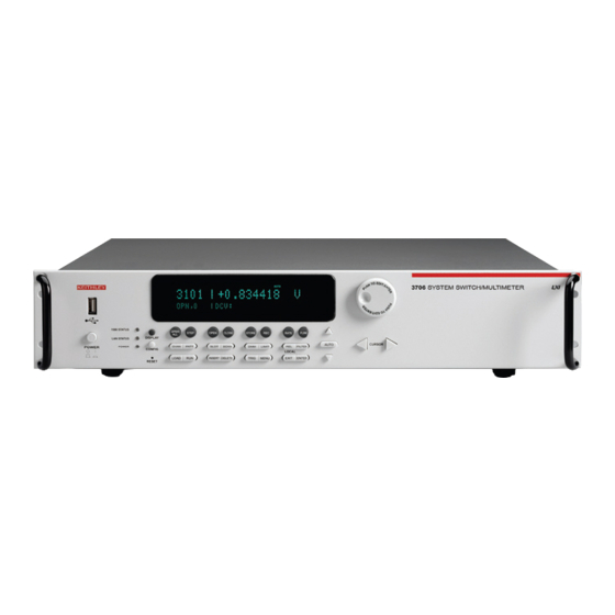
Section 2: Using the Front Panel Series 3700 System Switch/Multimeter User's Manual NOTE Only widths of one are supported by the front panel when reading or writing to a Digital I/O channel. Figure 2-1: Model 3706 System Switch/Multimeter Item Description Special keys and power switch (on page 2-10) Operation keys... -
Page 28: Figure 2-3: Model 3706-Nfp System Switch/Multimeter
Series 3700 System Switch/Multimeter User's Manual Section 2: Using the Front Panel To see current settings for LAN, see the applicable lan.status.* NOTE commands (for example, to see the present IP address of the Series 3700, send the following command: lan.status.ipaddress. Figure 2-3: Model 3706-NFP System Switch/Multimeter Figure 2-4: Model 3706-SNFP System Switch (no DMM) 3700S-900-01 Rev. -
Page 29: Display
Section 2: Using the Front Panel Series 3700 System Switch/Multimeter User's Manual Display The Series 3700 display provides visual information on the present active channel, including the channel selected (or range or pattern), channel state, last DMM measurement reading (where applicable), DMM settings (where applicable), and error indications. -
Page 30: Figure 2-5: Active Channel Display Example
Series 3700 System Switch/Multimeter User's Manual Section 2: Using the Front Panel Figure 2-5: Active channel display example The top line of the display (1) contains the following annunciators: Annunciator Description * (asterisk) Readings are being stored in the selected reading buffer. This is OFF when no buffer is selected or the selected buffer is full. - Page 31 Section 2: Using the Front Panel Series 3700 System Switch/Multimeter User's Manual Front panel DMM attribute Symbol Values + for ON or – for OFF auto zero + for ON or – for OFF line sync + for a limit enabled or – for limits disabled limit detector bandwidth 3, 30, or 300...
-
Page 32: Channel Type Indication
Series 3700 System Switch/Multimeter User's Manual Section 2: Using the Front Panel Figure 2-6: MAIN MENU display Channel type indication When selecting channels, the following information is displayed, which indicates the channel type on the front panel. For switch channels, the name of the assigned DMM configuration (for example, “nofunction”, “dcvolts”, “my4wire”, and so on) is displayed and below it, the channel state (for example, OPN or CLS, along with 2 or 4 for pole setting) is displayed. -
Page 33: Using The Front Panel With Non-Switch Channels
Section 2: Using the Front Panel Series 3700 System Switch/Multimeter User's Manual Using the front panel with non-switch channels To read a value from the main front panel screen, select the channel and press TRIG. To see a digital I/O channel in hex format (instead of normal binary) use CONFIG+TRIG. - Page 34 Series 3700 System Switch/Multimeter User's Manual Section 2: Using the Front Panel Front Panel Symbol Definition Symbol meaning Channel Setting I (uppercase Digital input mode Used with 6-character "i") label Digital output mode Used with 6-character label Digital output Used with 6-character protected mode label Totalizer mode...
-
Page 35: Special Keys And Power Switch
Section 2: Using the Front Panel Series 3700 System Switch/Multimeter User's Manual Front Panel Symbol Definition Symbol meaning Channel Setting Protected current Used with 12-character function 2 mode label or no label DAC output enable Output enable is Used with 6 or 12 settings disabled character label... - Page 36 Series 3700 System Switch/Multimeter User's Manual Section 2: Using the Front Panel The CHAN ATTR menu contains: LABEL: Sets the label associated with the specified channel. From the front panel, the label can be up to 12 characters. Remotely, the label may be up to 20 characters.
- Page 37 Section 2: Using the Front Panel Series 3700 System Switch/Multimeter User's Manual MODE Sets the mode attribute on a channel. Select one of the following options: INPUT OUTPUT OUTPUT_PROTECTED Related ICL command: channel.setmode(). MATCH Sets the match value on a channel. Enter the value as 8-bit binary. Related ICL command: channel.setmatch().
- Page 38 Series 3700 System Switch/Multimeter User's Manual Section 2: Using the Front Panel MODE Sets the mode attribute on a channel. Select one of the following options: EDGE. Indicates the edge for the Totalizer channel to increment its count. Select from one of the following options: FALLING RISING THRESHOLD.
- Page 39 Section 2: Using the Front Panel Series 3700 System Switch/Multimeter User's Manual POWER Sets the power state attribute on a channel. Select one of the following options: ENABLE DISABLE Related ICL command: channel.setpowerstate() CONFIG CHAN key - DAC channel type Press the CONFIG CHAN key to open the DAC ATTR menu.
-
Page 40: Display Key
Series 3700 System Switch/Multimeter User's Manual Section 2: Using the Front Panel MODE Sets the mode attribute on a channel. Select one of the following options: FUNCTION. Sets the desired function for a channel. Select one of the following options: VOLTAGE CURRENT_1 CURRENT_2... -
Page 41: Power Switch
Section 2: Using the Front Panel Series 3700 System Switch/Multimeter User's Manual POWER switch Press this switch to turn the Series 3700 on (I). Press it again to turn the Series 3700 off (O). RESET switch Use the RESET switch to restore the Series 3700 factory default LAN settings. Refer to the LAN functions and attributes (lan.config.x, where x represents the specific command) for factory default information. - Page 42 Series 3700 System Switch/Multimeter User's Manual Section 2: Using the Front Panel READ Displays a value from a channel as 8-bit binary. This menu option does not appear if a range of channels is selected. Related ICL command: channel.read(). NOTE Only widths of one are supported by the front panel when reading or writing to a Digital I/O channel.
- Page 43 Section 2: Using the Front Panel Series 3700 System Switch/Multimeter User's Manual RESET Restores the factory default settings of selected channels or all channels. Related ICL command: channel.reset(). CHAN key - DAC channel type Press the CHAN key to open the DAC ACTION menu. Unless noted, the menu option supports a range of selected channels.
-
Page 44: Delete Key
Series 3700 System Switch/Multimeter User's Manual Section 2: Using the Front Panel RESET Restores the factory default settings of selected channels or all channels. Related ICL command: channel.reset(). DELETE key Press the DELETE key to delete the first occurrence of the selected channel(s) or channel pattern (including function) from the scan list. - Page 45 Section 2: Using the Front Panel Series 3700 System Switch/Multimeter User's Manual DMM key configuration Press the CONFIG key and then the DMM key to open a DMM attribute menu for the active function. For example, if the DCV function is active, pressing the CONFIG key and then the DMM key opens the DC VOLT ATTR menu.
- Page 46 Series 3700 System Switch/Multimeter User's Manual Section 2: Using the Front Panel DRYCIRCUIT Configures the dry circuit setting for the selected DMM function. Related ICL command: dmm.drycircuit. FILTER Opens the FILTER menu for the selected DMM function. See FILTER key configuration (on page 2-24).
- Page 47 Section 2: Using the Front Panel Series 3700 System Switch/Multimeter User's Manual MATH Selecting the MATH menu item opens the MATH MENU. Items contained in this menu are: ENABLE: Enables or disables math operation on measurements. Related ICL command: dmm.math.enable. FORMAT: Specifies the math operation to perform on measurements.
-
Page 48: Enter Key
Series 3700 System Switch/Multimeter User's Manual Section 2: Using the Front Panel THERMO Selecting the THERMO menu item opens the THERMO menu. Items contained in this menu are: REFJUNCT: Allows selection of the reference junction to use. Available choices are: SIMULATED, EXTERNAL, or INTERNAL. Related ICL command: dmm.refjunction. -
Page 49: Exit Key
Section 2: Using the Front Panel Series 3700 System Switch/Multimeter User's Manual EXIT key Press the EXIT key to: Cancel the selection and to return to the previous menu display. Exit remote operation. Abort a scan that is running. Abort a script that is executing. FILTER key Press the FILTER key to enable and disable the filter for selected function. -
Page 50: Function Key
Series 3700 System Switch/Multimeter User's Manual Section 2: Using the Front Panel FUNCtion key Each press of the FUNC key immediately configures the DMM for the next function in the list: dcvolts: DC voltage acvolts: AC voltage dccurrent: DC current accurrent: AC current twowireohms: 2-wire ohm (resistance) fourwireohms: 4-wire ohm (resistance) -
Page 51: Limit Key
Section 2: Using the Front Panel Series 3700 System Switch/Multimeter User's Manual LIMIT key Press the LIMIT key to cycle through the four combinations of limit state settings: Limit1 and Limit2 off Limit1 on and Limit2 off Limit1 off and Limit2 on Limit1 and Limit2 on LIMIT key configuration Pressing the CONFIG key and then the LIMIT key opens the LIMIT menu. -
Page 52: Menu Key
Series 3700 System Switch/Multimeter User's Manual Section 2: Using the Front Panel MENU key Press the MENU key to open the MAIN menu. The MAIN menu contains the following items: SCRIPT: Opens the SCRIPT menu that contains LOAD and SAVE menu items. -
Page 53: Patt Key
Section 2: Using the Front Panel Series 3700 System Switch/Multimeter User's Manual PATT key Press the PATT key to open the PATTERN ACTION menu. If you press the PATT key, but no patterns have been created or if the unit is powered up with the factory default settings, the only option that is displayed is CREATE. -
Page 54: Rel Key
Series 3700 System Switch/Multimeter User's Manual Section 2: Using the Front Panel PATT key configuration Press the CONFIG key and then the PATT key to open the PATTERN ATTRibute menu. The PATTERN ATTRibute menu contains the following item: DMM_CONFIG: Sets the DMM configuration associated with the specified channel pattern. -
Page 55: Scan Key
Section 2: Using the Front Panel Series 3700 System Switch/Multimeter User's Manual SCAN key If the scan list is present, press the SCAN key to open the SCAN ACTION menu. The SCAN ACTION menu contains the following items: NOTE Use the INSERT key to create and add the present active channel to the scan list. -
Page 56: Slot Key
Series 3700 System Switch/Multimeter User's Manual Section 2: Using the Front Panel MODE: Sets the scan.mode value to one of the following: OPEN_ALL, which is equivalent to scan.MODE_OPEN_ALL or 0 (default setting) OPEN_SELECT, which is equivalent to scan.MODE_OPEN_SELECTIVE or 1 FIXED_ABR, which is equivalent to scan.MODE_FIXED_ABR or 2 Related ICL command: scan.mode() MEAS_CNT: Sets the measure count value. -
Page 57: Navigation Wheel
Section 2: Using the Front Panel Series 3700 System Switch/Multimeter User's Manual Navigation wheel Turn the navigation wheel to scroll to the desired menu option or to change the value of the selected numeric parameter. Pressing the navigation wheel has the same functionality as pressing the ENTER key. -
Page 58: Open Key
Series 3700 System Switch/Multimeter User's Manual Section 2: Using the Front Panel OPEN key Press the OPEN key to open selected channels or channel patterns. RATE key Press the RATE key to set the measurement speed (fast, medium, or slow) for the active or selected function. -
Page 59: Store Key
Section 2: Using the Front Panel Series 3700 System Switch/Multimeter User's Manual STORE key Press the STORE key to open the RD BUFF ACTION menu or <selected buffer name> menu. For more information, see Buffer: Data Storage and Retrieval. The RD BUFF ACTION menu contains the following items: CREATE: Allows creation of a reading buffer. -
Page 60: Rear Panel
Section 3 Rear Panel In this section: Rear panel summary ............3-1 Rear panel connections ............ 3-2 Switching module installation and connections ....3-7 Module installation ............3-8 Bus operation ..............3-12 Power-up ................. 3-14 Rear panel summary Figure 3-1: Rear panel features Item Description Analog backplane fuse... -
Page 61: Rear Panel Connections
8-1) for details. Slots Use any of the six slots of the Keithley Instruments Series 3700 for the switching modules. When a module is not installed, make sure to cover the slot with a slot cover. For additional information on an installed module, press the SLOT key (on page 2-31). -
Page 62: Digital I/O Port
Series 3700 System Switch/Multimeter User's Manual Section 3: Rear Panel Digital I/O port The Series 3700 has a digital input/output port that can be used to control external digital circuitry. For example, a handler that is used to perform binning operations can be used with a Digital I/O port. -
Page 63: Gpib Connector
Section 3: Rear Panel Series 3700 System Switch/Multimeter User's Manual Connecting cables Use a cable equipped with a standard male DB-25 connector (Keithley Instruments part number CA-126-1). Digital I/O lines (pins 1 through 14) The port provides 14 digital I/O lines. Each output is set high (+5V) or low (0V) and can read high or low logic levels. -
Page 64: Usb Connectors
Series 3700 System Switch/Multimeter User's Manual Section 3: Rear Panel USB connectors The downstream USB-2.0 receptacle (Type B) located on the rear panel connects to a host. The front panel has an upstream USB-2.0 connector (Type A) that connects to a user supplied USB flash drive. Use the rear connector to communicate with the instrument over USB by sending the desired commands. -
Page 65: Analog Backplane Connector
Section 3: Rear Panel Series 3700 System Switch/Multimeter User's Manual Analog backplane connector Refer to the following figure for analog backplane connector information. See Connections (on page 3-10) before making any connections. Figure 3-4: Analog backplane connector The table below contains pin numbers and descriptions for the analog backplane connector. -
Page 66: Switching Module Installation And Connections
Series 3700 System Switch/Multimeter User's Manual Section 3: Rear Panel Switching module installation and connections In order to exercise close/open operations explained in this section, a switching module (or pseudocard) must be installed in the mainframe. A switching module can be installed by the user, however external connections to the switching module are only to be performed by qualified service personnel. -
Page 67: Module Installation
Section 3: Rear Panel Series 3700 System Switch/Multimeter User's Manual Module installation WARNING Slot covers must be installed on unused slots to prevent personal contact with high voltage circuits. Perform the following steps to install a switching module into the Series 3700 mainframe: 1. -
Page 68: Figure 3-5: Typical Module Installation
Series 3700 System Switch/Multimeter User's Manual Section 3: Rear Panel Figure 3-5: Typical module installation Item Description Card guide (part of Series 3700) Module Card edge (part of module) Mounting screw (part of module) 3700S-900-01 Rev. C / July 2008... -
Page 69: Connections
Section 3: Rear Panel Series 3700 System Switch/Multimeter User's Manual Connections WARNING Connection information for switching modules is intended for qualified service personnel. Do not attempt to connect DUT or external circuitry to a switching module unless qualified to do so. To prevent electric shock that could result in serious injury or death, comply with these safety precautions: Before making or breaking any connections to the... -
Page 70: Pseudocards
Series 3700 System Switch/Multimeter User's Manual Section 3: Rear Panel As described in the International Electrotechnical Commission (IEC) Standard IEC 664, the Series 3700 is Installation Category I and must not be connected to mains. Pseudocards You can perform open/close/scan operations and configure your system without having an actual switching module installed in your Series 3700. -
Page 71: Bus Operation
Section 3: Rear Panel Series 3700 System Switch/Multimeter User's Manual A switching module can be installed in any of the mainframe's six slots. Therefore, to close, open, or scan a channel, you must specify the slot location and channel number of the switching module by using a four-digit channel number for the mainframe. - Page 72 Series 3700 System Switch/Multimeter User's Manual Section 3: Rear Panel Ethernet supports various settings. The LAN logical device has options that show the current status under lan.status commands while it has pending configuration settings under lan.config. The config settings will take effect when lan.applysettings is executed.
-
Page 73: Power-Up
Section 3: Rear Panel Series 3700 System Switch/Multimeter User's Manual Power-up Line power connection Follow the procedure below to connect the Series 3700 to line power and turn on the instrument. The Series 3700 operates from a line voltage of 100V to 240V at a frequency of 50Hz or 60Hz. -
Page 74: Power-Up Sequence
Reference manual.) NOTE If a problem develops while the instrument is under warranty, return it to Keithley Instruments, Inc., for repair. Assuming no errors occur, the Series 3700 will power-up as follows: 1. "No Comm Link" is briefly displayed. - Page 75 Section 3: Rear Panel Series 3700 System Switch/Multimeter User's Manual Beeper With the beeper enabled, a beep will be issued to acknowledge the following actions: A short beep, emulating a keyclick, is issued when a front panel key is pressed. A short beep, emulating a keyclick is also issued when the navigation wheel is turned or pressed.
-
Page 76: Close-Open Overview
Section 4 Close-open overview In this section: Overview ................4-1 Channel designations ............4-1 Channel attributes ............. 4-7 Closing and opening channels .......... 4-9 Channel patterns ............. 4-18 Relay closure count ............4-22 Identifying installed modules ........... 4-23 Overview NOTE This section provides basic close/open information for switching module channels. - Page 77 Section 4: Close-open overview Series 3700 System Switch/Multimeter User's Manual Backplane relay notation To control analog backplane relays for slots with analog backplane relay channels, use S9BX where: S: Slot number 9: Backplane notation designation (always 9 when referencing a backplane relay) B: Bank number X: Analog backplane relay number...
-
Page 78: Figure 4-1: Multiplexer Card Display
Series 3700 System Switch/Multimeter User's Manual Section 4: Close-open overview Figure 4-1: Multiplexer card display Matrix card notation To control channels using matrix card notation, use SRCC, where: S: Slot number R: Row number CC: Column number (always use 2 digits) Matrix channel examples: Reference Slot... -
Page 79: Selecting A Range Of Channels On The Front Panel
Section 4: Close-open overview Series 3700 System Switch/Multimeter User's Manual Figure 4-2: Matrix card display Selecting a range of channels on the front panel You can perform operations on a single channel or range of channels. Specify a channel range by selecting a starting channel number and ending channel number. - Page 80 Series 3700 System Switch/Multimeter User's Manual Section 4: Close-open overview 1. To change the present slot, press the navigation wheel, and the first digit of the four-digit channel number flashes, indicating edit mode. Turn the navigation wheel to change the number to select any slot that has a switching module or pseudocard installed.
-
Page 81: Channel List Parameter
Section 4: Close-open overview Series 3700 System Switch/Multimeter User's Manual Channel list parameter <ch_list> The channel list parameter <ch_list> is a string-type parameter that is used when controlling the relays of the Series 3700 using the remote command interface. You can specify a list of individual channels or a range of channels. Therefore, when sending this parameter: Enclose the contents of the channel list in either single (') or double (") quotes, but the quote style must match. -
Page 82: Channel Attributes
Series 3700 System Switch/Multimeter User's Manual Section 4: Close-open overview Channel attributes NOTE Analog backplane relays and channel patterns do not support all the attributes of switching module channels. Refer to Channel patterns (on page 4-18) for a discussion of channel pattern attributes. Each switching module channel has the following set of associated attributes: label: a string representing the channel (maximum length: 20 characters). - Page 83 Section 4: Close-open overview Series 3700 System Switch/Multimeter User's Manual close count: indicates how many times the relay for a channel has closed. A backplane relay has a close count associated with it as well. Refer to Relay closure count (on page 4-22) for information on querying this attribute.
-
Page 84: Setting And Querying Channel Attributes
Series 3700 System Switch/Multimeter User's Manual Section 4: Close-open overview Refer to Basic Digital Multimeter (DMM) Operation (on page 5-1) for more details on DMM functions, attributes, and configurations. Setting and querying channel attributes You can view and edit channel attributes on the front panel using the channel attributes menu. -
Page 85: Close/Open Channel Operations And Commands
Section 4: Close-open overview Series 3700 System Switch/Multimeter User's Manual Close/open channel operations and commands NOTE When the Series 3700 is powered up, all switch cards present in the system will have all their relays opened. This includes all switching and all backplane relays. -
Page 86: Figure 4-3: Two-Wire Function
Series 3700 System Switch/Multimeter User's Manual Section 4: Close-open overview Corresponding remote commands for switch with DMM operations: ICL command Action performed dmm.close() Equivalent of channel.exclusiveslotclose except it also prepares the DMM for taking a measurement on the function associated with the item. -
Page 87: Figure 4-4: Four-Wire Function
Section 4: Close-open overview Series 3700 System Switch/Multimeter User's Manual The following figure shows an example of how the channel and its paired channel are connected to the DMM Input and Sense terminals of the Series 3700 for a 4-wire DMM operation. Assume a switching module with 20 channels is installed in Slot 1 of the mainframe, and a 4-wire function, such as Ω4, is selected. -
Page 88: Front Panel Close And Open Keys
Series 3700 System Switch/Multimeter User's Manual Section 4: Close-open overview Front panel close and open keys You can use the front panel CLOSE and OPEN keys to perform either switch only operations or switch with DMM operations on the selected channel(s). The operations of the keys depend on the DMM configuration attribute setting of the selected channel. -
Page 89: Viewing Close/Open Status Of A Channel
Section 4: Close-open overview Series 3700 System Switch/Multimeter User's Manual For this example, the following numbered operations are executed either from the front panel or over the bus. Bulleted items that immediately follow the numbered operation indicate actions that can occur with the operation: 1. -
Page 90: Connection Methods For Close Operations
Series 3700 System Switch/Multimeter User's Manual Section 4: Close-open overview Viewing status from the front panel You can only view the status of a specific channel on the front panel. The selected channel appears in the right field on the display. Its status appears directly under the channel number. - Page 91 Section 4: Close-open overview Series 3700 System Switch/Multimeter User's Manual Channel connection rule: Break-Before-Make, Make-Before- Break The channel connect rule is a system-level attribute that determines the order of opening and closing channels when performing close operations that open and close multiple relays.
- Page 92 Series 3700 System Switch/Multimeter User's Manual Section 4: Close-open overview Using sequential connecting to achieve deterministic settling times Relays of a specific switching module have a specified settling time, which is also referred to as actuation time. You incur these settling times at each close or open operation for both switch-only and switch with DMM operations.
-
Page 93: Channel Patterns
Section 4: Close-open overview Series 3700 System Switch/Multimeter User's Manual Channel patterns You can use channel patterns as a convenient way to refer to an image of switching channels and backplane relays with a single alphanumeric name. Close or open operations on a channel pattern only control the channels and analog backplane relays included in the channel pattern image. - Page 94 Series 3700 System Switch/Multimeter User's Manual Section 4: Close-open overview To create a channel pattern using the remote command interface, use the channel.pattern.setimage or the channel.pattern.snapshot command. Refer to Instrument Control Library in the Series 3700 Reference Manual for more details. NOTE Channel patterns inherit the delay times of the individual channels that comprise the pattern.
- Page 95 Section 4: Close-open overview Series 3700 System Switch/Multimeter User's Manual Assigning channel pattern attributes A channel pattern has only two attributes: the channel pattern name and a DMM configuration. An error occurs if you attempt to assign or query any channel attributes other than DMM configuration for a channel pattern.
-
Page 96: Performing Close And Open Operations On Channel Patterns
Series 3700 System Switch/Multimeter User's Manual Section 4: Close-open overview To see the image associated with a channel pattern, use the channel.pattern.getimage command. For example, to see the image of the pattern, just created called 'one4wire': print(channel.pattern.getimage('one4wire')) 1001(1031),1911,1922 Paired channel are indicated in parentheses in <ch_list> queries. NOTE Performing close and open operations on channel patterns... -
Page 97: Relay Closure Count
Section 4: Close-open overview Series 3700 System Switch/Multimeter User's Manual Relay closure count The Series 3700 keeps an internal count of the number of times each switching module relay has been closed. The total number of relay closures is stored in nonvolatile memory on the switching module. -
Page 98: Identifying Installed Modules
Series 3700 System Switch/Multimeter User's Manual Section 4: Close-open overview Identifying installed modules Use the SLOT key to scroll through the model numbers, description, as well as the firmware revision of the installed switching module(s). Switching module queries (remote operation) Use print(slot[x].idn)to query and identify installed switching modules and channels that are closed: print(slot[x].idn) -
Page 100: Basic Digital Multimeter (Dmm) Operation
Section 5 Basic Digital Multimeter (DMM) Operation In this section: DMM measurement capabilities ........5-1 High-energy circuit safety precautions ......5-2 Performance considerations ..........5-3 Voltage measurements (DCV and ACV) ......5-7 Current measurements (DCI and ACI) ......5-25 AMPS analog backplane fuse replacement ....5-25 Resistance measurements .......... -
Page 101: High-Energy Circuit Safety Precautions
Section 5: Basic Digital Multimeter (DMM) Operation Series 3700 System Switch/Multimeter User's Manual TEMP: Temperature measurements from -200°C to 1820°C CONT: Continuity testing using the 1k range CAUTION When using a switching module, do not exceed the maximum signal levels of the module. High-energy circuit safety precautions To optimize safety when measuring voltage in high-energy distribution circuits, read and use the directions in the following warning:... -
Page 102: Performance Considerations
Series 3700 System Switch/Multimeter User's Manual Section 5: Basic Digital Multimeter (DMM) Operation Use the following procedure when testing power circuits: 1. De-energize the circuit using the regular installed connect-disconnect device. For example, remove the device's power cord or by turning off the power switch. -
Page 103: Line Cycle Synchronization
Section 5: Basic Digital Multimeter (DMM) Operation Series 3700 System Switch/Multimeter User's Manual NOTE To force a rapid update of the internal reference points, set the AUTOZERO attribute for the channel to ONCE. This will update the internal reference points once and stop. Querying the AUTOZERO setting will show it set to OFF. -
Page 104: Figure 5-1: Line Cycle Synchronization
Series 3700 System Switch/Multimeter User's Manual Section 5: Basic Digital Multimeter (DMM) Operation Figure 5-1: Line cycle synchronization 4-Wire Ohms are sensitive to 50 / 60Hz power line noise, due to cabling and Model 3700 switch card loop area. Figure 5-2: 4-Wire Line Synchronization Block Diagram 3700S-900-01 Rev. -
Page 105: Figure 5-3: 1Plc Line Sychronization Block Diagram
Section 5: Basic Digital Multimeter (DMM) Operation Series 3700 System Switch/Multimeter User's Manual Traditional DMM 4-wire measurements are made in two phases, SHI and SLO. If the dmm.nplc=1 or a multiple of the power line, theoretically, the average AC noise is 0. Refer to the 4W-Rdg calculation (http://www.maxim- ic.com/appnotes.cfm/appnote_number/1041/). -
Page 106: Voltage Measurements (Dcv And Acv)
Series 3700 System Switch/Multimeter User's Manual Section 5: Basic Digital Multimeter (DMM) Operation Figure 5-4: Line Sync Off and On <1plc Voltage measurements (DCV and ACV) The Series 3700 can make DCV measurements from 0.01μV to 300V and ACV measurements from 0.1μV to 300V RMS (425V peak for AC waveforms). DCV input resistance: 100mV through 10V ranges: >10GΩ... -
Page 107: Dcv Input Divider
Section 5: Basic Digital Multimeter (DMM) Operation Series 3700 System Switch/Multimeter User's Manual DCV input divider Normally, the input resistance for the 100mVDC, 1VDC, and 10VDC ranges is >10GΩ, while the input resistance of the 100VDC and 300VDC ranges is 10MΩ. However, the input resistance for the three lower DCV ranges can also be set to 10MΩ... -
Page 108: Figure 5-5: Dcv Connection
Series 3700 System Switch/Multimeter User's Manual Section 5: Basic Digital Multimeter (DMM) Operation Figure 5-5: DCV connection Figure 5-6: ACV connection 3700S-900-01 Rev. C / July 2008... -
Page 109: Fast Dcv Measurements
Section 5: Basic Digital Multimeter (DMM) Operation Series 3700 System Switch/Multimeter User's Manual Fast DCV measurements The following example script samples a 500Hz 70.7mV sine wave into the 100mVDC range at 0.0005plc with autozero and autodelay disabled. You can cut and paste the output data from the script into an editor like WordPad, where you can save it as a .csv (comma separated variable) file (using File >... -
Page 110: Schematic
Series 3700 System Switch/Multimeter User's Manual Section 5: Basic Digital Multimeter (DMM) Operation Schematic Refer to the following figure for a schematic of the rear panel, backplane, and DMM connect relays with a typical card. Figure 5-8: Rear panel to backplane to DMM connect relays schematic 3700S-900-01 Rev. -
Page 111: Voltage Measurement Procedure
Section 5: Basic Digital Multimeter (DMM) Operation Series 3700 System Switch/Multimeter User's Manual Voltage measurement procedure WARNING If both the analog backplane connector and a switching module's terminals are connected at the same time, all wiring and connections must be rated to the highest voltage that is connected. -
Page 112: Ac Voltage Measurements And Crest Factor
Series 3700 System Switch/Multimeter User's Manual Section 5: Basic Digital Multimeter (DMM) Operation Press a third time to select the end channel. Press a fourth time to allow DMM configuration assignment to the channel or range of channels. The ICL command reset() erases any channel assignments but NOTE maintains the user-defined configurations such as "my_dcv_conf1". -
Page 113: Figure 5-9: Acv Measurements: Sine Waves
Section 5: Basic Digital Multimeter (DMM) Operation Series 3700 System Switch/Multimeter User's Manual Figure 5-9: ACV measurements: sine waves 5-14 3700S-900-01 Rev. C / July 2008... -
Page 114: Figure 5-10: Acv Measurements: Square, Pulse, And Sawtooth Waves
Series 3700 System Switch/Multimeter User's Manual Section 5: Basic Digital Multimeter (DMM) Operation Figure 5-10: ACV measurements: square, pulse, and sawtooth waves 3700S-900-01 Rev. C / July 2008 5-15... -
Page 115: Auto Delay
Section 5: Basic Digital Multimeter (DMM) Operation Series 3700 System Switch/Multimeter User's Manual The Series 3700 is an AC-coupled RMS meter. For an AC waveform with DC content, the DC component is removed before the RMS is calculated. This affects the crest factor because the peak value for the DC-coupled waveform is different than the peak value for the AC-coupled waveform. - Page 116 Series 3700 System Switch/Multimeter User's Manual Section 5: Basic Digital Multimeter (DMM) Operation Auto delay modes Auto delay supports 3 modes: dmm.OFF or 0 dmm.ON or 1 dmm.AUTODELAY_ONCE or 2 For Off, the zero delay is applied at the start of measurement. For On, every start of measurement delays the same amount of time.
- Page 117 Section 5: Basic Digital Multimeter (DMM) Operation Series 3700 System Switch/Multimeter User's Manual Function Detector Range and delays Bandwidth 1 - 100Ω 1kΩ 10kΩ 100kΩ 1MΩ 10MΩ Range 100MΩ 2Ω and Autodelay 13ms 25ms 100ms 250ms 375ms 4Ω Auto Range 2.5ms 2.5ms 12.5ms...
-
Page 118: Measure Count
Series 3700 System Switch/Multimeter User's Manual Section 5: Basic Digital Multimeter (DMM) Operation Measure count The Series 3700 supports multi-sample measurements by using the dmm.measurecount ICL command. For a single ICL trigger, such as print(dmm.measure()), the DMM will take "n" measurements. This is useful in channel closures or a scan list where multiple measurements are required per channel. -
Page 119: Speed, Accuracy, And Settling Times For Ac Current And Voltage
Section 5: Basic Digital Multimeter (DMM) Operation Series 3700 System Switch/Multimeter User's Manual Speed, accuracy, and settling times for AC current and voltage The Series 3700 is an AC-coupled RMS meter. For an AC waveform with a DC content, the DC component is removed before the RMS is calculated. The RMS converter rectifies the AC waveform and creates a proportional DC level. -
Page 120: Figure 5-13: Two Channel Scan Alternating From 1Vac To 100Mvac, 1Khz, With A Measurecount Of
Series 3700 System Switch/Multimeter User's Manual Section 5: Basic Digital Multimeter (DMM) Operation Figure 5-13: Two Channel Scan alternating from 1Vac to 100mVac, 1KHz, with a Measurecount of 25 3700S-900-01 Rev. C / July 2008 5-21... - Page 121 Section 5: Basic Digital Multimeter (DMM) Operation Series 3700 System Switch/Multimeter User's Manual ACV Autodelay Once script example -- Script Name. loadscript test_acv_autodelay -- Resets the 3706 to factory defaults. reset() -- Break-before-make off. Fastest closure method. channel.connectrule=channel.OFF dmm.func="acvolts" dmm.range=1 -- Default bandwidth setting.
-
Page 122: Low Level Considerations
Series 3700 System Switch/Multimeter User's Manual Section 5: Basic Digital Multimeter (DMM) Operation -- buf.timestamp includes date and real time. -- Note that x,x prints reading and time vertically for easy copy / paste to Excel endscript This table illustrates how to optimize ACV or ACI for input signal frequency, reading rate, autodelay, and measure count. - Page 123 Section 5: Basic Digital Multimeter (DMM) Operation Series 3700 System Switch/Multimeter User's Manual Shielding AC voltages that are extremely large compared with the DC signal to be measured may produce an erroneous output. Therefore, to minimize AC interference, the circuit should be shielded with the shield connected to the Series 3700 input low (particularly for low level sources).
-
Page 124: Current Measurements (Dci And Aci)
Series 3700 System Switch/Multimeter User's Manual Section 5: Basic Digital Multimeter (DMM) Operation AC voltage offset The Series 3700, at 5½ digits resolution, will typically display 100 counts of offset on AC volts with the input shorted. This offset is caused by the offset of the TRMS converter. -
Page 125: Resistance Measurements
3. Remove the fuse and replace it with the same type (3A, 250V, fast-blow, 5 × 20mm). The Keithley Instruments part number is FU-99-1. 4. Install the new fuse by reversing the procedure above. -
Page 126: Offset Compensated Ohms (Oc+)
Series 3700 System Switch/Multimeter User's Manual Section 5: Basic Digital Multimeter (DMM) Operation When measuring resistance >10K-ohms, cable and 3700 card capacitance, along with dielectric absorption, can cause additional uncertainties, such as low readings. The low readings are caused by insufficient settling time after the closure of a Model 3700 switch card channel. -
Page 127: Amps Measurement Procedure
Section 5: Basic Digital Multimeter (DMM) Operation Series 3700 System Switch/Multimeter User's Manual Amps measurement procedure 1. Press the OPENALL key to open all switching channels. Refer to the DCV section on how to select a DMM function, range, filter setting, and more. NOTE The Model 3721 switch card is the only card that supports DCI or ACI functions. -
Page 128: Connections
Series 3700 System Switch/Multimeter User's Manual Section 5: Basic Digital Multimeter (DMM) Operation Connections Analog backplane connector (rear panel) Connections for resistance measurements are shown below. For 2-wire resistance measurements ( 2), connect the leads to INPUT HI and Figure 5-14: Two-wire resistance measurements 3700S-900-01 Rev. -
Page 129: Figure 5-15: Four-Wire Resistance Measurement
Section 5: Basic Digital Multimeter (DMM) Operation Series 3700 System Switch/Multimeter User's Manual For 4-wire resistance ( 4), connect the leads to INPUT HI and LO, and sense 4 HI and LO. Figure 5-15: Four-wire resistance measurement Switching module Connections for the switching module are shown below. As shown, each of the 40 channels can be used to perform 2W measurements. -
Page 130: Figure 5-17: Four-Wire Switching Module Resistance Connection
Series 3700 System Switch/Multimeter User's Manual Section 5: Basic Digital Multimeter (DMM) Operation For 4W measurements, a channel pair is used for each 4-wire measurement as shown. For 4W connections on a 40-channel switching module, Channels 1 through 20 (which are used as the INPUT terminals) are paired to Channels 21 through 40 (which are used as the SENSE terminals). -
Page 131: Standard Resistance Measurements
Section 5: Basic Digital Multimeter (DMM) Operation Series 3700 System Switch/Multimeter User's Manual Standard resistance measurements CAUTION Inputs: Do not apply more than 425V peak between INPUT HI and LO, or instrument damage may occur. CAUTION Switching cards: Do not apply more than 300V DC or 300V RMS (425V peak) for AC waveforms between any two pins, or switching module damage may occur. -
Page 132: Figure 5-18: Enabling Offset-Compensated Ohms
Series 3700 System Switch/Multimeter User's Manual Section 5: Basic Digital Multimeter (DMM) Operation The offset-compensated ohms reading is then calculated as follows: Offset-compensated ohms reading = V/ I where: V = V2 - V1 I = I2 - I1 V1 is the voltage measurement with the current source at its normal level. V2 is the voltage measurement using the lowest current source setting. -
Page 133: Figure 5-19: Four-Wire Ohm Attr Menu: Offsetcomp
Section 5: Basic Digital Multimeter (DMM) Operation Series 3700 System Switch/Multimeter User's Manual NOTE The Series 3700 is in 4-wire ohm mode when the 4W is displayed. Offset compensation is active when the OC+ is displayed (OC- is shown in the above figure). 1. -
Page 134: Dry Circuit Ohms (Dry+)
Series 3700 System Switch/Multimeter User's Manual Section 5: Basic Digital Multimeter (DMM) Operation Offset compensation can be enabled for any 4-wire range. The internal DMM will perform offset compensation for the <=10k-ohm ranges and automatically disable for >=100K-ohm ranges. Send the following ICL commands and the Model 3706 returns the reading and a "1"... - Page 135 Section 5: Basic Digital Multimeter (DMM) Operation Series 3700 System Switch/Multimeter User's Manual Measuring contact resistance (oxide film build-up) The ideal resistance between switch connectors, or relay contacts is 0 . However, an oxide film may be present on the switch or relay contacts. This oxide film could add resistance on the order of several hundred milli- s.
-
Page 136: Figure 5-20: Enabling Dry-Circuit Ohms
Series 3700 System Switch/Multimeter User's Manual Section 5: Basic Digital Multimeter (DMM) Operation NOTE If the Series 3700 is in remote mode (controlled over the bus) press the EXIT key to place it in local mode to control the unit using the front panel keys. - Page 137 Section 5: Basic Digital Multimeter (DMM) Operation Series 3700 System Switch/Multimeter User's Manual Performing dry circuit ohms measurements Dry circuit ohms can only be performed on the 4W function using the 1 , 10 , 100 , 1k or 10k ranges (maximum resistance of 2.4k ). Make sure you use 4-wire connections to the DUT as detailed in Analog backplane connector (rear panel)
-
Page 138: Measurement Methods
Series 3700 System Switch/Multimeter User's Manual Section 5: Basic Digital Multimeter (DMM) Operation Dry circuit ohms measurement considerations Dry circuit ohms uses a constant current source with voltage monitoring that is used to clamp the current source voltage. The current source will remain constant as long as the monitoring voltage is <20mV. -
Page 139: Figure 5-22: Two-Wire Constant-Current Source Method
Section 5: Basic Digital Multimeter (DMM) Operation Series 3700 System Switch/Multimeter User's Manual The 2-wire constant-current method is shown below. Figure 5-22: Two-wire constant-current source method The 4-wire constant-current method is shown below. Figure 5-23: Four-wire constant-current source method Ratiometric method For the 10M and 100M ranges, the ratiometric method is used to measure resistance. -
Page 140: Figure 5-24: Two-Wire Ratiometric Method
Series 3700 System Switch/Multimeter User's Manual Section 5: Basic Digital Multimeter (DMM) Operation Figure 5-24: Two-wire ratiometric method Because I = V/R, Equation 1 is modified using the V/R equivalents in place of I and I . Therefore: = (V ) + (V SOUR MEAS... -
Page 141: Figure 5-25: Four-Wire Ratiometric Method
Section 5: Basic Digital Multimeter (DMM) Operation Series 3700 System Switch/Multimeter User's Manual Note that V includes the voltage drops of the input test leads (Input HI and MEAS Input LO). Therefore, the actual voltage drop across the DUT is V minus the MEAS two voltage drops in the test leads. -
Page 142: Figure 5-26: Fast Alternating Scan Block Diagram
Series 3700 System Switch/Multimeter User's Manual Section 5: Basic Digital Multimeter (DMM) Operation Figure 5-26: Fast Alternating Scan block diagram 3700S-900-01 Rev. C / July 2008 5-43... - Page 143 Section 5: Basic Digital Multimeter (DMM) Operation Series 3700 System Switch/Multimeter User's Manual Fast Alternating Scan, DCV, and 2W The following example illustrates how to configure a Model 3706 and 3723 switch card for fast alternating function scans. The example shows channel 1 measuring +7.5VDC and channel 2 measuring a 1K-ohm resistor.
-
Page 144: Open Lead Detection
Series 3700 System Switch/Multimeter User's Manual Section 5: Basic Digital Multimeter (DMM) Operation scan.create('4004, 4024') -- Backplane channel 4911 and 4921 will be automatically paired. -- Scan will loop 10 times. scan.scancount=10 -- Starts scan. scan.execute(buf) for x=1,buf.n do printbuffer(x,x,buf, buf.relativetimestamps) end -- Prints the reading and relative time from start of scan. -
Page 145: Figure 5-27: Simplified Normal 4W Open Detection Schematic
Section 5: Basic Digital Multimeter (DMM) Operation Series 3700 System Switch/Multimeter User's Manual Figure 5-27: Simplified normal 4W open detection schematic 5-46 3700S-900-01 Rev. C / July 2008... -
Page 146: Figure 5-28: Model 3706 Internal Dmm
Series 3700 System Switch/Multimeter User's Manual Section 5: Basic Digital Multimeter (DMM) Operation Figure 5-28: Model 3706 Internal DMM ISOUR open voltage 1 through 1M ranges: A hardware detector is used to detect an open input lead. The hardware detector uses a comparator circuit to monitor the voltage on the ohm I terminal. -
Page 147: Figure 5-29: 4W Open Detector With 3700 Card
Section 5: Basic Digital Multimeter (DMM) Operation Series 3700 System Switch/Multimeter User's Manual Range SHI or SLO High Limit SHI or SLO Low Limit MEAS MEAS Open Lead Detection Open Lead Detection > 12.8V < -1.0V Calculated measurement open voltage A calculated measurement, which exceed 120% of the range, will return an overflow reading. - Page 148 Series 3700 System Switch/Multimeter User's Manual Section 5: Basic Digital Multimeter (DMM) Operation dmm.opendetector open voltage With dmm.opendetector = dmm.ON, a separate -1.5 A I SHI and a OPENLEAD separate SLO current source, will pulse on and off before the start of each measurement while I remains enabled.
- Page 149 OPENLEAD print(dmm.opendetector) returns 1.0. 4. Additional cable and Model 3700 card capacitance can increase settle times, resulting in additional measurement uncertainty. Keithley Instruments recommend the use of Teflon or other low-dielectric absorption wire insulation for these measurements. 5-50...
-
Page 150: Figure 5-30: Simplified Dry-Circuit Open V-Clamp Feedback Loop Schematic
Series 3700 System Switch/Multimeter User's Manual Section 5: Basic Digital Multimeter (DMM) Operation 4-wire dry-circuit open lead detection The Series 3700 dry-circuit resistance measurement circuitry was designed for low power, low glitch, and low open voltage applications such as GMRR head testing and air bag / squib test that require low energy resistance sourcing. -
Page 151: Temperature Measurements
Section 5: Basic Digital Multimeter (DMM) Operation Series 3700 System Switch/Multimeter User's Manual VMEAS open voltage (dry-circuit) If either Input Sense HI or Sense LO V is outside the enclosed table voltages, MEAS the A/D will abort in <100 sec and return an overflow reading. Range SHI or SLO High Limit SHI or SLO Low Limit Open... - Page 152 Series 3700 System Switch/Multimeter User's Manual Section 5: Basic Digital Multimeter (DMM) Operation Type Range Resolution -200°C to +400°C 0.001°C -150°C to +1000°C 0.001°C 0°C to +1768°C 0.1°C 0°C to +1786°C 0.1°C +350°C to +1820°C 0.1°C When two wires made up of dissimilar metals are joined together, a voltage is generated.
- Page 153 Section 5: Basic Digital Multimeter (DMM) Operation Series 3700 System Switch/Multimeter User's Manual Simulated reference junction An example of a simulated reference junction is an ice bath as shown in the paragraph titled Thermocouple connections (on page 5-58). The copper wire to thermocouple wire connections are immersed (but electrically isolated) in the ice bath, and the user enters the 0°C simulated reference temperature into the Series 3700.
- Page 154 Series 3700 System Switch/Multimeter User's Manual Section 5: Basic Digital Multimeter (DMM) Operation External reference junction Thermocouple readings may be configured to use an external reference junction setting. The Series 3700 assumes the external reference junction is connected to channel 1 of a slot. It is recommend that this channel be configured for thermistor or RTD temperature reading.
- Page 155 Section 5: Basic Digital Multimeter (DMM) Operation Series 3700 System Switch/Multimeter User's Manual If during a measurement cycle, with dmm.opendetector = dmm.ON, the ohm's function 100 A I is pulsed on and off before the start of each SOUR measurement. The A/D will monitor for 0.8msec.
-
Page 156: Figure 5-31: Thermocouple Open Detector Drawing
Series 3700 System Switch/Multimeter User's Manual Section 5: Basic Digital Multimeter (DMM) Operation The following figure provides a schematic representation of the Series 3700 open thermocouple detection. Figure 5-31: Thermocouple Open Detector drawing 3700S-900-01 Rev. C / July 2008 5-57... - Page 157 Section 5: Basic Digital Multimeter (DMM) Operation Series 3700 System Switch/Multimeter User's Manual Thermocouple connections Connections for thermocouples are shown below. Thermocouples are color coded to identify the positive (+) and negative (-) leads (see the table). Note that the negative (-) lead for U.S. type T/Cs is red. T/C type Positive Negative (-)
-
Page 158: Figure 5-32: Simulated Reference Junction
Series 3700 System Switch/Multimeter User's Manual Section 5: Basic Digital Multimeter (DMM) Operation Figure 5-32: Simulated reference junction NOTE The positive lead of the type T thermocouple is made of copper. Therefore, that lead can be connected directly to the input of the switching module (it does not have to be maintained at the simulated reference temperature, in other words, immersed in an ice bath). - Page 159 Section 5: Basic Digital Multimeter (DMM) Operation Series 3700 System Switch/Multimeter User's Manual Thermocouple temperature measurement configuration To configure temperature measurements from the front panel: NOTE Refer to DCV section DMM function configuration. 1. Set thermocouple device attributes: Turn the navigation wheel to scroll to the "THERMO" menu item and press the navigation wheel or the ENTER key.
-
Page 160: Thermistors
Series 3700 System Switch/Multimeter User's Manual Section 5: Basic Digital Multimeter (DMM) Operation scan.execute(buf) for x=1, buf.n do printbuffer (x,x,buf) end channel.open("allslots") endscript Thermistors The temperature measurement range for thermistors is -80°C to 150°C (0.01° resolution). Thermistor types that are supported include the 2.2k , 5k , and 10k types. -
Page 161: Figure 5-35: Thermistor Analog Backplane Connection
Section 5: Basic Digital Multimeter (DMM) Operation Series 3700 System Switch/Multimeter User's Manual Thermistor connections A thermistor can be connected directly to the analog backplane connector (or to any of the applicable input channels of a thermistor capable switching module). Figure 5-35: Thermistor analog backplane connection Figure 5-36: Thermistor switching module connection 5-62... - Page 162 Series 3700 System Switch/Multimeter User's Manual Section 5: Basic Digital Multimeter (DMM) Operation Thermistor measurement configuration To configure thermistor measurements from the front panel: 1. If needed, change to the temperature function ("TMP" is displayed) by pressing the FUNC key. 2.
-
Page 163: Rtds (Resistance Temperature Detector)
Section 5: Basic Digital Multimeter (DMM) Operation Series 3700 System Switch/Multimeter User's Manual RTDs (Resistance Temperature Detector) For 4-wire resistance temperature detectors (RTDs) the temperature measurement range is -200°C to 630°C (0.01°C resolution). The Series 3700 supports 4-wire RTD types including: PT100, D100, F100, PT385, and PT3916. A USER type is also available to modify RTD parameters, such as the resistance at 0°C. -
Page 164: Figure 5-37: Three-Wire Rtd Connections
Series 3700 System Switch/Multimeter User's Manual Section 5: Basic Digital Multimeter (DMM) Operation Figure 5-37: Three-wire RTD connections Figure 5-38: Three-wire RTD switching module connections 3700S-900-01 Rev. C / July 2008 5-65... -
Page 165: Figure 5-39: Four-Wire Rtd Connections
Section 5: Basic Digital Multimeter (DMM) Operation Series 3700 System Switch/Multimeter User's Manual 4-wire RTD connections Shown below are 4-wire RTD connections to the Series 3700. For a 4-wire RTD capable 40-channel switching module, paired channels are used to perform the 4-wire measurement. - Page 166 Series 3700 System Switch/Multimeter User's Manual Section 5: Basic Digital Multimeter (DMM) Operation Ω at 0°C Type Standard Alpha Beta Delta 100Ω PT100 ITS-90 0.00385055 0.10863 1.49990 100Ω D100 ITS-90 0.003920 0.10630 1.49710 100Ω F100 ITS-90 0.003900 0.11000 1.49589 100Ω PT385 IPTS-68 0.003850...
-
Page 167: Temperature Measurement Configuration
Section 5: Basic Digital Multimeter (DMM) Operation Series 3700 System Switch/Multimeter User's Manual For example, these ICL commands configure temperature function to a custom RTD and assign it to a 10-channel scan list. reset() dmm.func=dmm.TEMPERATURE -- or 3, or dmm.TEMP_FOURRTD, or 4 dmm.transducer= dmm.TEMP_THREERTD -- dmm.fourrtd also supported dmm.threertd=dmm.RTD_USER... -
Page 168: Temperature Measurement Procedure
Series 3700 System Switch/Multimeter User's Manual Section 5: Basic Digital Multimeter (DMM) Operation Temperature measurement procedure NOTE If the Series 3700 is in remote, place the unit in local by pressing the EXIT key. 1. Press the OPENALL key to open all switching channels. 2. -
Page 169: Trigger Level
Section 5: Basic Digital Multimeter (DMM) Operation Series 3700 System Switch/Multimeter User's Manual Trigger level Frequency and period use a zero-crossing trigger, meaning that a count is taken when the frequency crosses the zero level. The Series 3700 uses a reciprocal counting technique to measure frequency and period. -
Page 170: Frequency And Period Measurement Procedure
Series 3700 System Switch/Multimeter User's Manual Section 5: Basic Digital Multimeter (DMM) Operation Figure 5-42: FREQ and PERIOD connections (switching module) Frequency and period measurement procedure CAUTION Do not apply more than the maximum input levels for the Series 3700 or installed switching module (whichever is lower) or instrument damage may occur. -
Page 171: Continuity Testing
Section 5: Basic Digital Multimeter (DMM) Operation Series 3700 System Switch/Multimeter User's Manual 5. Press the TRIG key and observe the displayed reading. 6. To measure other switching channels, repeat steps 5 and 6. 7. When finished, press the OPENALL key to open all channels. Also see the bus command dmm.threshold for more information on NOTE threshold attributes. -
Page 172: Continuity Testing Procedure
Series 3700 System Switch/Multimeter User's Manual Section 5: Basic Digital Multimeter (DMM) Operation Connections to test continuity using a switching module are shown below. Because this is a 2-wire ohms measurement, Channels 1 through 40 of a 40- channel switching module can be used. Figure 5-44: Continuity connections using a switching module Continuity testing procedure NOTE... -
Page 173: Accuracy Calculations
Section 5: Basic Digital Multimeter (DMM) Operation Series 3700 System Switch/Multimeter User's Manual 5. To disable continuity testing, select a different function (for example, DCV). 6. When finished, press the OPENALL key to open all channels. NOTE Limits and digital outputs cannot be used when testing continuity with the continuity (CNT) function. -
Page 174: Calculating Ac Characteristics Accuracy
Series 3700 System Switch/Multimeter User's Manual Section 5: Basic Digital Multimeter (DMM) Operation For example, to calculate the accuracy of the above example at 0.006plc: Accuracy = +/- (( 25ppm of reading) + ( 2ppm of range ) + ( 2.5 x 7ppm of range )) = +/- (( 25ppm x 5V ) + ( 2ppm x 10V ) + ( 2.5 x 7ppm x 10V )) = +/- ( 125uV + 20uV + 175uV ) = +/- 320uV... -
Page 175: Additional Derating Factors
Section 5: Basic Digital Multimeter (DMM) Operation Series 3700 System Switch/Multimeter User's Manual As an example of how to calculate the actual readings limits for dB, with a user- defined VREF of 10V, you must calculate the voltage accuracy and apply it to the above equation. -
Page 176: Optimizing Measurement Accuracy
Series 3700 System Switch/Multimeter User's Manual Section 5: Basic Digital Multimeter (DMM) Operation Optimizing measurement accuracy The configurations listed below assume that the multimeter after an ICL command reset(). Enclosed are two charts that represent RMS Noise versus Aperture Time (or NPLC) and Reading Rate versus Aperture Time (or NPLC). -
Page 177: Dc Voltage, Dc Current, And Resistance
Section 5: Basic Digital Multimeter (DMM) Operation Series 3700 System Switch/Multimeter User's Manual Figure 5-46: RMS Noise vs. Aperture Time DC voltage, DC current, and resistance 1 or 5 PLC, filter off, fixed range. Use REL on DC voltage and 2-wire resistance measurements when appropriate. -
Page 178: Optimizing Measurement Speed
Series 3700 System Switch/Multimeter User's Manual Section 5: Basic Digital Multimeter (DMM) Operation Optimizing measurement speed The configurations listed below assume that the multimeter is configured after the ICL command reset(). DC voltage, DC current, and resistance Select: dmm.autozero=dmm.OFF dmm.autodelay=dmm.OFF dmm.nplc=0.0005 dmm.filter=dmm.OFF dmm.autorange=dmm.OFF... -
Page 180: Model 3750 Additional Information
Section 6 Model 3750 Additional Information In this section: Digital I/O ................6-1 Counter/totalizer ..............6-7 Analog output ..............6-9 Using match counts ............6-21 Latching values ............... 6-23 Power consumption implications ........6-24 Digital I/O CAUTION Do not exceed the maximum rated voltages and currents for the digital I/O banks. -
Page 181: Simplified Jumper Configuration Model
Section 6: Model 3750 Additional Information Series 3700 System Switch/Multimeter User's Manual Simplified jumper configuration model Digital outputs can be jumpered to either an internal +5 V or an external voltage. The diagram below shows a simplified schematic. Figure 6-1: Simplified schematic of the jumper configuration 3700S-900-01 Rev. -
Page 182: Figure 6-2: Simplified Schematic Of A Digital I/O Channel
Series 3700 System Switch/Multimeter User's Manual Section 6: Model 3750 Additional Information The factory default jumpers are set as follows: Connects the digital lines on each bank to the internal pull-up resistors. Connects those pull-up resistors to the internal +5 V. Connects VEXT1 to VEXT2. -
Page 183: Sourcing Current To An External Load
Section 6: Model 3750 Additional Information Series 3700 System Switch/Multimeter User's Manual The figure shows a simplified schematic for one bit of a digital I/O channel. Each I/O bit has an optional pullup resistor in parallel with a diode that is used to clamp flyback voltages from inductive devices like electro-mechanical relays. -
Page 184: Programming Overview
Series 3700 System Switch/Multimeter User's Manual Section 6: Model 3750 Additional Information Programming overview There are five banks of 8 bits each on the Model 3750 card. The following examples apply to the card as shipped, as the jumpers are set to the position that pulls them up internally to +5 V. - Page 185 Section 6: Model 3750 Additional Information Series 3700 System Switch/Multimeter User's Manual To read and write banks using a scan Any input bank or totalizer channel that is included in a scan list is read when that channel is scanned. The value is saved to the buffer specified for the scan. For digital inputs, the width defaults to 1.
-
Page 186: Counter/Totalizer
Series 3700 System Switch/Multimeter User's Manual Section 6: Model 3750 Additional Information Counter/totalizer CAUTION Do not exceed the maximum voltage and currents as listed on the Model 3750 specifications. Unused inputs should not be left floating but should be tied to ground or an appropriate DC voltage. -
Page 187: Using The Gating Function
Section 6: Model 3750 Additional Information Series 3700 System Switch/Multimeter User's Manual To read the current total closure counts: channel.setmode('1009', channel.MODE_RISING_TTL_EDGE) count = channel.read('1009') To reset the counter to zero using an explicit command: channel.write('1009', 0) To preset the counter to a value (for example, 100) using an explicit command: channel.write('1009', 100) To automatically reset the counter back to zero for a read command:... -
Page 188: Analog Output
Series 3700 System Switch/Multimeter User's Manual Section 6: Model 3750 Additional Information NOTE The minimum gate input setup time must be satisfied for the event to be counted. Analog output There are two channels of isolated analog outputs on the Model 3750 card. Each channel can be configured for either voltage output or current output. -
Page 189: Configuring The Card For Output Type
Section 6: Model 3750 Additional Information Series 3700 System Switch/Multimeter User's Manual Configuring the card for output type The analog output channels default to voltage outputs. To configure them as current outputs: channel.setmode('1010', channel.MODE_CURRENT_1) NOTE MODE_CURRENT_1 specifies 0-20 mA and MODE_CURRENT_2 specifies 4-20 mA. -
Page 190: Using The Card When Configured As Voltage Outputs
Series 3700 System Switch/Multimeter User's Manual Section 6: Model 3750 Additional Information Using the card when configured as voltage outputs To set the analog voltage output level to -3.5 volts: channel.setmode('1010', channel.MODE_VOLTAGE_1) channel.setoutputenable('1010', channel.ON) channel.write('1010', -3.5) Once the output voltage is set and the output is enabled, the output attempts to drive the external circuitry to the value specified. -
Page 191: Using The Card When Configured As Current Outputs
Section 6: Model 3750 Additional Information Series 3700 System Switch/Multimeter User's Manual Using the card when configured as current outputs To set a current output to 10mA: channel.setmode('1010', channel.MODE_CURRENT_1) channel.setoutputenable('1010', channel.ON) channel.write('1010', 10e-3) Once the output current is set and the output is enabled, the output attempts to drive the external circuitry to the value specified. -
Page 192: Output Loading Precautions
Series 3700 System Switch/Multimeter User's Manual Section 6: Model 3750 Additional Information Output loading precautions In addition to the maximum specified loads for the output voltage and current, note several other precautions: Excessive amounts of capacitance present on the voltage output nodes can affect their normal behavior. -
Page 193: Hardware Configuration
Section 6: Model 3750 Additional Information Series 3700 System Switch/Multimeter User's Manual Hardware configuration To configure digital I/O pull-up resistors and VEXT sources, you must remove and partially disassemble the Model 3750 as shown. CAUTION Be sure to use proper anti-static procedures while handling the Model 3750. -
Page 194: Figure 6-6: Location Of P3 And J5 Jumpers
Series 3700 System Switch/Multimeter User's Manual Section 6: Model 3750 Additional Information Figure 6-6: Location of P3 and J5 jumpers The connector labeled P3 contains all of the jumpers needed to configure digital I/O and VEXT1, VEXT2. The connector labeled J5 contains a single jumper option that configures the backplane relays. -
Page 195: Calibration
Section 6: Model 3750 Additional Information Series 3700 System Switch/Multimeter User's Manual Desired effect P3 pin numbers Connect VEXT1 to VEXT2 Jumper 17 - 18 For backplane configuration at J5, jumper pins 2-3 to allow the Model 3750 to make backplane connections during calibration with a system DMM. If you do not want to ever physically allow the Model 3750 to make backplane connections, jumper pins 1-2. - Page 196 Series 3700 System Switch/Multimeter User's Manual Section 6: Model 3750 Additional Information Preparing for calibration Before performing the calibration steps, be sure that the Model 3750 is properly disconnected from all external circuits. If an in-system DMM is to be used, disconnect the external ABUS from other mainframes and instruments that might be connected.
- Page 197 Section 6: Model 3750 Additional Information Series 3700 System Switch/Multimeter User's Manual Calibration steps for counter/totalizer channels For totalizer channels, a calibration sequence includes these steps: 1. Calibrate 0 V Totalizer Threshold 2. Calibrate 1.5 V Totalizer Threshold You must save the calibration after calibrating and before locking. Use channel.calibration.save() to execute this function.
- Page 198 Series 3700 System Switch/Multimeter User's Manual Section 6: Model 3750 Additional Information -- Write the reading/value into the appropriate step number channel.calibration.step("" .. channel_num,1) delay(6) rdg=dmm.measure() print(rdg) channel.calibration.step("" .. channel_num,2,rdg) dmm.range=1 channel.calibration.step("" .. channel_num,3) delay(6) rdg=dmm.measure() print(rdg) channel.calibration.step("" .. channel_num,4,rdg) dmm.range=10 channel.calibration.step(""...
- Page 199 Section 6: Model 3750 Additional Information Series 3700 System Switch/Multimeter User's Manual -- if it is not saved. channel.calibration.save() channel.calibration.lock() -- Cleanup to restore analog channels to -- an idle, unconnected state channel.setmode("" .. (1000 * slot_num + 10),channel.MODE_PROTECT_VOLTAGE_1) channel.setmode("" .. (1000 * slot_num + 11),channel.MODE_PROTECT_VOLTAGE_1) channel.setoutputenable(""...
-
Page 200: Power Consumption Information
Series 3700 System Switch/Multimeter User's Manual Section 6: Model 3750 Additional Information Power consumption information You can power off each analog channel if it is not being used to reduce the power required of the card with channel.setpowerstate(). The card has a default static power draw of 3300 mW, which includes powering the totalizer channels and both analog output channels. -
Page 201: Using Match Counts To Generate An Event
Section 6: Model 3750 Additional Information Series 3700 System Switch/Multimeter User's Manual Once the match count is met in the totalizer, the channel.IND_MATCH bit is set and can be read using match_value = channel.getstate('1006') Because the default setting for the state is for it to latch, the value remains even after the count moves beyond the match value. -
Page 202: Latching Values
Series 3700 System Switch/Multimeter User's Manual Section 6: Model 3750 Additional Information Latching values Channels support a status/state concept. The status of a channel indicates what conditions are present on that channel at that point in time. Examples of channel status are: An overload condition exists on that channel A channel is presently matching a pre-determined match condition... -
Page 203: Power Consumption Implications
Section 6: Model 3750 Additional Information Series 3700 System Switch/Multimeter User's Manual Power consumption implications The Model 3750 draws a significant amount of power from the Model 3706 mainframe in order to perform all of its functions. In cases where multiple Model 3750 cards are used, it is possible that not all Model 3750 functions can be executed at the same time. -
Page 204: Upgrade Procedure Using Usb Flash Drive
Section 7 Upgrade Procedure Using USB Flash Drive In this section: Firmware upgrade from a USB flash drive ......7-1 Upgrade procedure ............7-2 Firmware upgrade from a USB flash drive Use this procedure to upgrade the Series 3700 firmware directly from a USB flash drive using a *.cab file. -
Page 205: Upgrade Procedure
Section 7: Upgrade Procedure Using USB Flash Drive Series 3700 System Switch/Multimeter User's Manual Upgrade procedure NOTE You can upgrade a single card at a later time by populating the mainframe with that card and re-running the upgrade procedure. The upgrade procedure verifies that other parts of the system are already at the latest revision and only upgrades the additional installed card. -
Page 206: Maintenance
Introduction ............... 8-1 Fuse replacement ............. 8-1 Front panel tests ............... 8-2 Introduction The information in this section deals with routine maintenance of Keithley Instruments Series 3700 System Switch Multimeter instruments that can be performed by the operator. Fuse replacement The analog backplane AMPS fuse (see item 1 in Fuse location figure) is accessible from the rear panel, just below the analog backplane connector. -
Page 207: Front Panel Tests
3. Reinstall the fuse holder. If the fuse continues to blow, a circuit malfunction exists and must be corrected. Return the unit to Keithley Instruments for repair. Front panel tests There are two front panel tests: One to test the functionality of the front panel keys and one to test the display. -
Page 208: Test Procedure
Series 3700 System Switch/Multimeter User's Manual Section 8: Maintenance Test procedure The front panel keys test lets you check the functionality of each front panel key. To run the front panel keys test: 1. Display the MAIN MENU by pressing the MENU key. 2. -
Page 210: Series 3700 Module Schematics And Connections
Model 3750 Multifunction I/O Card ........9-65 Maximum power usage with Series 3700 cards The Series 3700 series offers a growing family of high-density and general- purpose plug-in cards that accommodates a broad range of signals at very competitive pricing. The Series 3700 supports applications as diverse as design validation, accelerated stress testing, data acquisition, and functional testing. -
Page 211: Power Budgeting And Calculation
Section 9: Series 3700 Module Schematics and Connections Series 3700 System Switch/Multimeter User's Manual Power budgeting and calculation Individual relay power consumption generally depends on the type of relay. Latching type relays consume power only briefly in order to open or close. These types of relays are not of concern for power budgeting purposes. - Page 212 Series 3700 System Switch/Multimeter User's Manual Section 9: Series 3700 Module Schematics and Connections Model Quiescent Channel Relay Power Backplane Relay Power Consumption Power Consumption (Milliwatts) (Milliwatts) Each (Milliwatts) Each 3750 3300 0 each (Digital Input channel) NOTE: The 3300 is 365 each (Digital reduced Output channel)
-
Page 213: Power Budgeting Examples
Section 9: Series 3700 Module Schematics and Connections Series 3700 System Switch/Multimeter User's Manual To check power consumption, each slot power must be computed. The slot power for slots 1 through 3 are added. Also, slot power for slots 4 through 6 is added. - Page 214 Series 3700 System Switch/Multimeter User's Manual Section 9: Series 3700 Module Schematics and Connections Example 2 This example is for a partially loaded Model 3706 with Model 3723 cards (all 1- pole mode). Slot # Card Channel relays closed Backplane relays closed SLOT 1 3723 SLOT 2...
- Page 215 Section 9: Series 3700 Module Schematics and Connections Series 3700 System Switch/Multimeter User's Manual Slot # Card Channel relays closed Backplane relays closed SLOT 6 3723 This produces the following power consumption: Slot #1 Power Consumed = 60 x 100 4 x 100 7100 Slot #2 Power Consumed =...
- Page 216 Series 3700 System Switch/Multimeter User's Manual Section 9: Series 3700 Module Schematics and Connections Example 4 This example is for a fully loaded 3706-S with mix of cards. Slot # Card Channel relays closed Backplane relays closed SLOT 1 3720 SLOT 2 3721 SLOT 3...
- Page 217 Section 9: Series 3700 Module Schematics and Connections Series 3700 System Switch/Multimeter User's Manual Setup Power Notes CH 11 = I mode Total Power 4970 m NOTE: Since total power per bank cannot exceed 12300 mW, only 2 3750 cards per bank can be populated when used in the example configuration.
-
Page 218: Pseudocards
Series 3700 System Switch/Multimeter User's Manual Section 9: Series 3700 Module Schematics and Connections Pseudocards A pseudocard can be "installed" in any empty slot. With the 3720 pseudocard "installed," the instrument operates as if a Model 3720 Thermocouple MUX card is installed in the slot. -
Page 219: Hardware Interlocks
Section 9: Series 3700 Module Schematics and Connections Series 3700 System Switch/Multimeter User's Manual Query the slot[X] attributes to determine the capabilities of the installed switching modules. For example, send the following query to determine if Slot 1 supports common-side 4-wire channels: CommonSideOhms1 = slot[1].commonsideohms Hardware interlocks... -
Page 220: Engaging Hardware Interlocks
Series 3700 System Switch/Multimeter User's Manual Section 9: Series 3700 Module Schematics and Connections Engaging hardware interlocks To engage the hardware interlocks, you must provide a low resistance path between the two applicable interlock pins as shown in the diagram. This path routes a 5 V power source to an onboard interlock relay which in turn enables power to the backplane relays. -
Page 221: Interlock Pin Numbers
Section 9: Series 3700 Module Schematics and Connections Series 3700 System Switch/Multimeter User's Manual See Section 9 of the Reference Manual for more interlock related commands and details. Interlock pin numbers The following table shows the interlock pin numbers for all applicable switching modules. -
Page 222: Model 3720 Dual 1X30 Multiplexer Card
Series 3700 System Switch/Multimeter User's Manual Section 9: Series 3700 Module Schematics and Connections Model 3720 dual 1x30 multiplexer card The Model 3720 offers two independent banks of 1×30 two-pole multiplexers. It is ideal for general-purpose switching, including temperature measurements. The two banks can automatically be connected to the Series 3700 mainframe backplane and optional DMM through the analog backplane connection relays. -
Page 223: Connection Information: Model 3720
Section 9: Series 3700 Module Schematics and Connections Series 3700 System Switch/Multimeter User's Manual 7401: Type K thermocouple wire kit Connection information: Model 3720 Refer to the following figure for Model 3720 D-sub connection information. Figure 9-4: D-sub connection information for the Model 3720 9-14 3700S-900-01 Rev. -
Page 224: Schematics: Model 3720
Series 3700 System Switch/Multimeter User's Manual Section 9: Series 3700 Module Schematics and Connections Schematics: Model 3720 The following figure provides a switching schematic for the Model 3720. Figure 9-5: Schematic of the Model 3720 3700S-900-01 Rev. C / July 2008 9-15... -
Page 225: Figure 9-6: Models 3720, 3723, And 3724 Screw Terminal
Section 9: Series 3700 Module Schematics and Connections Series 3700 System Switch/Multimeter User's Manual Figure 9-6: Models 3720, 3723, and 3724 screw terminal 9-16 3700S-900-01 Rev. C / July 2008... -
Page 226: Model 3720 Connection Log
Series 3700 System Switch/Multimeter User's Manual Section 9: Series 3700 Module Schematics and Connections Model 3720 connection log The following figures provide a sample of a connection log that can be used to record the wiring scheme for this module. Figure 9-7: Sample Model 3720 connection log (1 of 2) 3700S-900-01 Rev. -
Page 227: Figure 9-8: Sample Model 3720 Connection Log (2 Of 2)
Section 9: Series 3700 Module Schematics and Connections Series 3700 System Switch/Multimeter User's Manual Figure 9-8: Sample Model 3720 connection log (2 of 2) 9-18 3700S-900-01 Rev. C / July 2008... -
Page 228: Model 3721 Dual 1X20 Multiplexer Card
Series 3700 System Switch/Multimeter User's Manual Section 9: Series 3700 Module Schematics and Connections Model 3721 dual 1x20 multiplexer card The Model 3721 provides 40 differential channels and automatic CJC with 3721- ST accessory. The Model 3721 has two independent banks of 1x20 two-pole multiplexers that are ideal for general-purpose switching, including temperature measurements. -
Page 229: Model 3721-St Accessory Board Channel List
Section 9: Series 3700 Module Schematics and Connections Series 3700 System Switch/Multimeter User's Manual Model 3721-ST accessory board channel list The following table shows the association between the Model 3721-ST accessory and each channel on the Model 3721. Channel 3721-ST Terminal Board Silkscreen Label Multiplexer # 1 Output MUX 1 OUT 1 ... -
Page 230: Connection Information: Model 3721
Series 3700 System Switch/Multimeter User's Manual Section 9: Series 3700 Module Schematics and Connections Connection information: Model 3721 Refer to the following figure for Model 3721 D-sub connection information. Figure 9-10: D-sub connection information for the Model 3721 3700S-900-01 Rev. C / July 2008 9-21... -
Page 231: Schematics: Model 3721
Section 9: Series 3700 Module Schematics and Connections Series 3700 System Switch/Multimeter User's Manual Schematics: Model 3721 The following figure provides a switching schematic for the Model 3721 in two- pole mode. Figure 9-11: Schematic of the Model 3721 in two-pole mode 9-22 3700S-900-01 Rev. -
Page 232: Figure 9-12: Schematic Of The Model 3721 In Four-Wire Common Side Ohm Mode
Series 3700 System Switch/Multimeter User's Manual Section 9: Series 3700 Module Schematics and Connections The following figure provides a switching schematic for the Model 3721 in 4-wire common side ohm mode. Figure 9-12: Schematic of the Model 3721 in four-wire common side ohm mode Programming Note The 3721 card that has three additional backplane relays for common side ohms functionality. -
Page 233: Model 3721: Amps Channels Fuse Replacement
Section 9: Series 3700 Module Schematics and Connections Series 3700 System Switch/Multimeter User's Manual Model 3721: AMPS channels fuse replacement Channels 41 and 42 are protected by series fuses. In the event of an overload, both channels and the DMM input are protected. The two fuses are replaceable and are located on the printed circuit board of the Model 3721 switch card. -
Page 234: Figure 9-13: Removing The Top Shield
Section 9: Series 3700 Module Schematics and Connections Figure 9-13: Removing the top shield Figure 9-14: Fuse location Rating Type Size Keithley Instruments part number 250 V, 3A Fast blow 5 x 20 mm FU-99-1 3700S-900-01 Rev. C / July 2008... -
Page 235: Figure 9-15: Model 3721-St
Section 9: Series 3700 Module Schematics and Connections Series 3700 System Switch/Multimeter User's Manual Figure 9-15: Model 3721-ST 9-26 3700S-900-01 Rev. C / July 2008... -
Page 236: Model 3721 Connection Log
Series 3700 System Switch/Multimeter User's Manual Section 9: Series 3700 Module Schematics and Connections Model 3721 connection log The following figures provide a sample of a connection log that can be used to record the wiring scheme for this module. Figure 9-16: Sample Model 3721 connection log (1 of 2) 3700S-900-01 Rev. -
Page 237: Figure 9-17: Sample Model 3721 Connection Log (2 Of 2)
Section 9: Series 3700 Module Schematics and Connections Series 3700 System Switch/Multimeter User's Manual Figure 9-17: Sample Model 3721 connection log (2 of 2) 9-28 3700S-900-01 Rev. C / July 2008... -
Page 238: Model 3722 Dual 1X48 High-Density Multiplexer Card
Series 3700 System Switch/Multimeter User's Manual Section 9: Series 3700 Module Schematics and Connections Model 3722 dual 1x48 high-density multiplexer card The Model 3722 has two independent banks of 1x48 two-pole multiplexers, which is ideal for applications that require a high channel count. The two banks can automatically be connected to the Series 3700 mainframe backplane and optional DMM through the analog backplane connection relays. -
Page 239: Connection Information: Model 3722
Section 9: Series 3700 Module Schematics and Connections Series 3700 System Switch/Multimeter User's Manual Connection information: Model 3722 Refer to the following figure for Model 3722 D-sub connection information. Figure 9-19: D-sub connection information the Model 3722 9-30 3700S-900-01 Rev. C / July 2008... -
Page 240: Schematics: Model 3722
Series 3700 System Switch/Multimeter User's Manual Section 9: Series 3700 Module Schematics and Connections Schematics: Model 3722 The following figure provides a switching schematic for the Model 3722. Figure 9-20: Schematic for the Model 3722 3700S-900-01 Rev. C / July 2008 9-31... -
Page 241: Model 3722 Connection Log
Section 9: Series 3700 Module Schematics and Connections Series 3700 System Switch/Multimeter User's Manual Model 3722 connection log The following figures provide a sample of a connection log that can be used to record the wiring scheme for this module. Figure 9-21: Sample Model 3722 connection log (1 of 3) 9-32 3700S-900-01 Rev. -
Page 242: Figure 9-22: Sample Model 3722 Connection Log (2 Of 3)
Series 3700 System Switch/Multimeter User's Manual Section 9: Series 3700 Module Schematics and Connections Figure 9-22: Sample Model 3722 connection log (2 of 3) 3700S-900-01 Rev. C / July 2008 9-33... -
Page 243: Figure 9-23: Sample Model 3722 Connection Log (3 Of 3)
Section 9: Series 3700 Module Schematics and Connections Series 3700 System Switch/Multimeter User's Manual Figure 9-23: Sample Model 3722 connection log (3 of 3) 9-34 3700S-900-01 Rev. C / July 2008... -
Page 244: Model 3723 Dual 1×30 High-Speed Multiplexer Card
Series 3700 System Switch/Multimeter User's Manual Section 9: Series 3700 Module Schematics and Connections Model 3723 dual 1×30 high-speed multiplexer card The Model 3723 has two independent banks of high-speed 1×30 two-pole multiplexers that are ideal for high-speed scanning applications. The two banks can automatically be connected to the Series 3700 mainframe backplane and optional DMM through the analog backplane connection relays. -
Page 245: Connection Information: Model 3723
Section 9: Series 3700 Module Schematics and Connections Series 3700 System Switch/Multimeter User's Manual Connection information: Model 3723 Refer to the following figure for Model 3723 D-sub connection information. Figure 9-25: D-sub connection information for the Model 3723 (two-pole mode) 9-36 3700S-900-01 Rev. -
Page 246: Figure 9-26: D-Sub Connection Information For The Model 3723 (One-Pole Mode)
Series 3700 System Switch/Multimeter User's Manual Section 9: Series 3700 Module Schematics and Connections Figure 9-26: D-sub connection information for the Model 3723 (one-pole mode) 3700S-900-01 Rev. C / July 2008 9-37... -
Page 247: Schematics: Model 3723
Section 9: Series 3700 Module Schematics and Connections Series 3700 System Switch/Multimeter User's Manual Schematics: Model 3723 The following figure provides a switching schematic for the Model 3723 in two- pole mode. Figure 9-27: Schematic for the Model 3723 in two-pole mode 9-38 3700S-900-01 Rev. -
Page 248: Figure 9-28: Schematic: Model 3723 In One-Pole Mode
Series 3700 System Switch/Multimeter User's Manual Section 9: Series 3700 Module Schematics and Connections The following figure provides a switching schematic for the Model 3723 in single- pole mode. Figure 9-28: Schematic: Model 3723 in one-pole mode 3700S-900-01 Rev. C / July 2008 9-39... -
Page 249: Figure 9-29: Models 3720, 3723, And 3724 Screw Terminal
Section 9: Series 3700 Module Schematics and Connections Series 3700 System Switch/Multimeter User's Manual Figure 9-29: Models 3720, 3723, and 3724 screw terminal 9-40 3700S-900-01 Rev. C / July 2008... - Page 250 Series 3700 System Switch/Multimeter User's Manual Section 9: Series 3700 Module Schematics and Connections Figure 9-30: Model 3723-ST-1 3700S-900-01 Rev. C / July 2008 9-41...
-
Page 251: Model 3723 Connection Log (60-Channel)
Section 9: Series 3700 Module Schematics and Connections Series 3700 System Switch/Multimeter User's Manual Model 3723 connection log (60-channel) The following figures provide a sample of a connection log that can be used to record the wiring scheme for this module. Figure 9-31: Sample Model 3723 connection log (60-channel) (1 of 2) 9-42 3700S-900-01 Rev. -
Page 252: Figure 9-32: Sample Model 3723 Connection Log (60-Channel) (2 Of 2)
Series 3700 System Switch/Multimeter User's Manual Section 9: Series 3700 Module Schematics and Connections Figure 9-32: Sample Model 3723 connection log (60-channel) (2 of 2) 3700S-900-01 Rev. C / July 2008 9-43... -
Page 253: Model 3723 Connection Log (120-Channel)
Section 9: Series 3700 Module Schematics and Connections Series 3700 System Switch/Multimeter User's Manual Model 3723 connection log (120-channel) The following figures provide a sample of a connection log that can be used to record the wiring scheme for this module. Figure 9-33: Sample Model 3723 connection log (120-channel) (1 of 4) 9-44 3700S-900-01 Rev. -
Page 254: Figure 9-34: Sample Model 3723 Connection Log (120-Channel) (2 Of 4)
Series 3700 System Switch/Multimeter User's Manual Section 9: Series 3700 Module Schematics and Connections Figure 9-34: Sample Model 3723 connection log (120-channel) (2 of 4) 3700S-900-01 Rev. C / July 2008 9-45... -
Page 255: Figure 9-35: Sample Model 3723 Connection Log (120-Channel) (3 Of 4)
Section 9: Series 3700 Module Schematics and Connections Series 3700 System Switch/Multimeter User's Manual Figure 9-35: Sample Model 3723 connection log (120-channel) (3 of 4) 9-46 3700S-900-01 Rev. C / July 2008... -
Page 256: Figure 9-36: Sample Model 3723 Connection Log (120-Channel) (4 Of 4)
Series 3700 System Switch/Multimeter User's Manual Section 9: Series 3700 Module Schematics and Connections Figure 9-36: Sample Model 3723 connection log (120-channel) (4 of 4) 3700S-900-01 Rev. C / July 2008 9-47... -
Page 257: Model 3724 Dual 1X30 Fet Multiplexer Specifications
Section 9: Series 3700 Module Schematics and Connections Series 3700 System Switch/Multimeter User's Manual Model 3724 Dual 1x30 FET Multiplexer Specifications The Model 3724 has two independent banks of 1×30 2-pole multiplexers. It is ideal for general-purpose switching, including temperature measurements. The two banks can automatically be connected to the Series 3700 mainframe backplane and optional DMM through the analog backplane connection relays. -
Page 258: Available Accessories: Model 3724
Series 3700 System Switch/Multimeter User's Manual Section 9: Series 3700 Module Schematics and Connections Available accessories: Model 3724 3791-KIT78-R 78-pin, female D-sub connector kit (contains 2 female D-sub connectors and 156 solder cups) 3720-MTC-3 78-pin. D-sub female-to-male cable, 3 m (9.8 ft) 3720-MTC-1.5 78-pin D-sub female-to-male cable, 1.5 m (4.9 ft) 3724-ST... -
Page 259: Schematics: Model 3724
Section 9: Series 3700 Module Schematics and Connections Series 3700 System Switch/Multimeter User's Manual Schematics: Model 3724 Figure 9-39: Model 3724 schematic 9-50 3700S-900-01 Rev. C / July 2008... -
Page 260: Model 3724 Connection Log
Series 3700 System Switch/Multimeter User's Manual Section 9: Series 3700 Module Schematics and Connections Figure 9-40: Models 3720, 3723, and 3724 screw terminal Model 3724 connection log The following table provides a sample of a connection log that can be used to record the wiring scheme for this module. - Page 261 Section 9: Series 3700 Module Schematics and Connections Series 3700 System Switch/Multimeter User's Manual Channel Color Pin Number CH10 CH11 CH12 CH13 CH14 CH15 CH16 CH17 CH18 CH19 CH20 CH21 CH22 CH23 CH24 CH25 CH26 CH27 CH28 CH29 9-52 3700S-900-01 Rev. C / July 2008...
- Page 262 Series 3700 System Switch/Multimeter User's Manual Section 9: Series 3700 Module Schematics and Connections Channel Color Pin Number CH30 OUTPUT 2 CH31 CH32 CH33 CH34 CH35 CH36 CH37 CH38 CH39 CH40 CH41 CH42 CH43 CH44 CH45 CH46 CH47 CH48 CH49 3700S-900-01 Rev.
- Page 263 Section 9: Series 3700 Module Schematics and Connections Series 3700 System Switch/Multimeter User's Manual Channel Color Pin Number CH50 CH51 CH52 CH53 CH54 CH55 CH56 CH57 CH58 CH59 CH60 9-54 3700S-900-01 Rev. C / July 2008...
-
Page 264: Model 3730 6×16 High-Density Matrix Card
Series 3700 System Switch/Multimeter User's Manual Section 9: Series 3700 Module Schematics and Connections Model 3730 6×16 high-density matrix card The Model 3730 is a two-pole, 6 row by 16 column matrix card. It can connect up to six differential instrument channels to any combination of 16 DUTs (devices under test). -
Page 265: Connection Information: Model 3730
Section 9: Series 3700 Module Schematics and Connections Series 3700 System Switch/Multimeter User's Manual Connection information: Model 3730 Refer to the following figure for Model 3730 D-sub connection information. Figure 9-42: D-sub connection information for the Model 3730 9-56 3700S-900-01 Rev. C / July 2008... -
Page 266: Schematics: Model 3730
Series 3700 System Switch/Multimeter User's Manual Section 9: Series 3700 Module Schematics and Connections Schematics: Model 3730 The following figure provides a switching schematic for the Model 3730. Figure 9-43: Schematic of the Model 3730 The channels on the 3730 are matrix channels. Unlike MUX channels, matrix channels do not have a DMM configuration associated with them. -
Page 267: Figure 9-44: Model 3730-St
Section 9: Series 3700 Module Schematics and Connections Series 3700 System Switch/Multimeter User's Manual Figure 9-44: Model 3730-ST 9-58 3700S-900-01 Rev. C / July 2008... -
Page 268: Model 3730 Connection Log
Series 3700 System Switch/Multimeter User's Manual Section 9: Series 3700 Module Schematics and Connections Model 3730 connection log The following figures provide a sample of a connection log that can be used to record the wiring scheme for this module. Figure 9-45: Sample Model 3730 connection log 3700S-900-01 Rev. -
Page 269: Model 3740 32-Channel Isolated Switch Card
Section 9: Series 3700 Module Schematics and Connections Series 3700 System Switch/Multimeter User's Manual Model 3740 32-channel isolated switch card The Model 3740 offers 28 general-purpose form C channels that are ideal for routing power or other control devices. For higher power applications of up to 7 A, four additional high-current form A channels are provided. -
Page 270: Connection Information: Model 3740
Series 3700 System Switch/Multimeter User's Manual Section 9: Series 3700 Module Schematics and Connections Connection information: Model 3740 Refer to the following figure for Model 3740 D-sub connection information. Figure 9-47: D-sub connection information for the Model 3740 3700S-900-01 Rev. C / July 2008 9-61... -
Page 271: Schematics: Model 3740
Section 9: Series 3700 Module Schematics and Connections Series 3700 System Switch/Multimeter User's Manual Schematics: Model 3740 The following figure provides a switching schematic for the Model 3740. Figure 9-48: Schematic for the Model 3740 9-62 3700S-900-01 Rev. C / July 2008... -
Page 272: Figure 9-49: Model 3740-St
Series 3700 System Switch/Multimeter User's Manual Section 9: Series 3700 Module Schematics and Connections Figure 9-49: Model 3740-ST 3700S-900-01 Rev. C / July 2008 9-63... -
Page 273: Model 3740 Connection Log
Section 9: Series 3700 Module Schematics and Connections Series 3700 System Switch/Multimeter User's Manual Model 3740 connection log The following figures provide a sample of a connection log that can be used to record the wiring scheme for this module. Figure 9-50: Sample Model 3740 connection log (1 of 2) 9-64 3700S-900-01 Rev. -
Page 274: Model 3750 Multifunction I/O Card
Series 3700 System Switch/Multimeter User's Manual Section 9: Series 3700 Module Schematics and Connections Figure 9-51: Sample Model 3740 connection log (2 of 2) Model 3750 Multifunction I/O Card The Model 3750 Multifunction I/O Card has 40 bidirectional digital I/O bits arranged in five banks of eight bits each. -
Page 275: Available Accessories: Model 3750
Section 9: Series 3700 Module Schematics and Connections Series 3700 System Switch/Multimeter User's Manual Figure 9-52: Model 3750 Multifunction I/O Card Available accessories: Model 3750 3750-ST Screw terminal panel 3790-KIT50-R 50-pin, female, D-sub connector kit (solder cup contacts). See Connection information: Model 3730 (on page 9-56). -
Page 276: Connection Information: Model 3750
Series 3700 System Switch/Multimeter User's Manual Section 9: Series 3700 Module Schematics and Connections Connection information: Model 3750 Figure 9-53: Model 3750 connection information 3700S-900-01 Rev. C / July 2008 9-67... -
Page 277: Schematics: Model 3750
Section 9: Series 3700 Module Schematics and Connections Series 3700 System Switch/Multimeter User's Manual Schematics: Model 3750 Figure 9-54: Model 3750 screw terminal schematic Model 3750 connection log The following figures provide a sample of a connection log that can be used to record the wiring scheme for this module. - Page 278 Series 3700 System Switch/Multimeter User's Manual Section 9: Series 3700 Module Schematics and Connections Channel Color Pin Number CH1 - DIO3 CH1 - DIO4 CH1 - DIO5 CH1 - DIO6 CH1 - DIO7 CH1 - DIO8 CH2 - DIO1 CH2 - DIO2 CH2 - DIO3 CH2 - DIO4 CH2 - DIO5...
- Page 279 Section 9: Series 3700 Module Schematics and Connections Series 3700 System Switch/Multimeter User's Manual Channel Color Pin Number CH5 - DIO4 CH5 - DIO5 CH5 - DIO6 CH5 - DIO7 CH5 - DIO8 CH6 - Gate+ CH6 - Gate- CH6 - Input+ CH6 - Input- CH7 - Gate+ CH7 - Gate-...
- Page 280 Series 3700 System Switch/Multimeter User's Manual Section 9: Series 3700 Module Schematics and Connections 3700S-900-01 Rev. C / July 2008 9-71...
-
Page 282: Index
Index accessories, available • 9-13, 9-19, 9-29, 9-35, 9-55, 9-60 +5 output • 3-4 accuracy calculations • 5-74 < ACI current measurements • 5-25 <ch_list> queries • 4-6 action keys action keys • 2-33 2-wire CLOSE • 2-32 constant-current method • 5-39 OPEN •... - Page 283 Index Series 3700 System Switch/Multimeter User's Manual connector • 3-6, 5-29 DC characteristics accuracy • 5- APERTURE • 2-20 auto open voltage • 5-75 and auto range settings • 5-17 calculations definition • 5-16 accuracy • 5-74 modes • 5-17 CHAN key •...
- Page 284 Series 3700 System Switch/Multimeter User's Manual Index channel patterns • 4-18, 4-19, 4-20, 4-21 close channel operations • 4-10 channel type indication • 2-7 CLOSE key • 2-32, 4-13 characteristics accuracy • 5-75 CONFIG key • 2-10 DBREF • 2-20 configuration non-switch channels •...
- Page 285 Index Series 3700 System Switch/Multimeter User's Manual DISPLAY key • 2-15 key • 2-24 key configuration • 2-21, 2-24 key • 2-19 frequency key configuration • 2-20 connections • 5-70 measurement capabilities • 5-1 frequency measurements dry circuit ohms and period measurements, ranges •...
- Page 286 Series 3700 System Switch/Multimeter User's Manual Index LIMIT • 2-26 LOAD • 2-26 INPUTDIV • 2-21 MENU • 2-27 INSERT key • 2-25 OPEN • 2-33 interlock OPEN ALL • 2-32 hardware • 9-11 PATT • 2-28 pin numbers • 9-12 RANGE •...
- Page 287 Index Series 3700 System Switch/Multimeter User's Manual Model 3740 • 9-60, 9-64 maintenance • 8-1 modules channel assignments • 3-11 Make-Before-Break • 4-16 cold junction • 5-54 MATH • 2-22 connection warning • 3-10 matrix card notation • 4-3 hardware interlocks • 9-10 measure identify installed •...
- Page 288 Series 3700 System Switch/Multimeter User's Manual Index OPENDETECT • 2-22 power budgeting • 9-2, 9-4 POWER switch • 2-16 operation keys CHAN • See CHAN key power usage • 9-1 DELETE • 2-19 precautions • 5-2 ENTER • 2-23 pseudocards • 3-11, 9-9 EXIT •...
- Page 289 Index Series 3700 System Switch/Multimeter User's Manual Ethernet connector • 3-4 AC functions, not available • 5-4 RTD • 5-64, 5-66, 5-67 system RUN key • 2-29 identification • 3-15 SCAN temperature configuration • 2-30 measurement configuration • 5- key • 2-30 measurement procedure •...
- Page 290 Series 3700 System Switch/Multimeter User's Manual Index voltage autozero • 5-3 calculated measurement • 5-48 ISOUR open • 5-47 warm-up • 5-3 wheel, navigation • 2-32 3700S-900-01 Rev. C / July 2008 Index-9...
- Page 291 Service Form Model No. Serial No. Date Name and Telephone No. Company List all control settings, describe problem and check boxes that apply to problem. ❏ ❏ ❏ Intermittent Analog output follows display Particular range or function bad; specify ❏ ❏...
- Page 292 M E A S U R E C O N F I D E N C E Keithley Instruments, Inc. Corporate Headquarters • 28775 Aurora Road • Cleveland, Ohio 44139 • 440-248-0400 • Fax: 440-248-6168 • 1-888-KEITHLEY • www.keithley.com 12/06...
Need help?
Do you have a question about the 3700 Series and is the answer not in the manual?
Questions and answers