Table of Contents
Advertisement
Quick Links
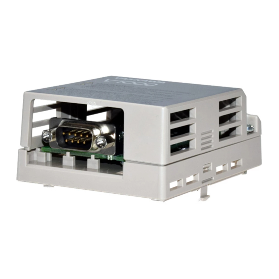
YASKAWA AC Drive-V1000 Option
Modbus TCP/IP
Installation Manual
Type: SI-EM3/V
To properly use the product, read this manual thoroughly and retain
for easy reference, inspection, and maintenance. Ensure the end user
receives this manual.
V1000
オプションユニット
Modbus TCP/IP
取扱説明書
形 式
SI-EM3/V
製品を安全にお使いいただくために,本書を必ずお読みください。
また,本書をお手元に保管していただくとともに,最終的に本製品をご使用になる
ユーザー様のお手元に確実に届けられるよう,お取り計らい願います。
MANUAL NO. TOBP C730600 59B
通信
Advertisement
Table of Contents

Related Manuals for YASKAWA SI-EM3/V


Summary of Contents for YASKAWA SI-EM3/V
- Page 1 YASKAWA AC Drive-V1000 Option Modbus TCP/IP Installation Manual Type: SI-EM3/V To properly use the product, read this manual thoroughly and retain for easy reference, inspection, and maintenance. Ensure the end user receives this manual. V1000 オプションユニット Modbus TCP/IP 通信 取扱説明書...
- Page 2 Yaskawa. No patent liability is assumed with respect to the use of the information contained herein. Moreover, because Yaskawa is constantly striving to improve its high-quality products, the information contained in this manual is subject to change without notice.
-
Page 3: Table Of Contents
11 SPECIFICATIONS ....... 49 YASKAWA ELECTRIC TOBP C730600 59B V1000 Option SI-EM3/V Installation Manual... -
Page 4: Preface And Safety
Any warnings provided by YASKAWA must be promptly provided to the end user. YASKAWA offers an express warranty only as to the quality of its products in conforming to standards and specifications published in the manual. NO OTHER WARRANTY, EXPRESS OR IMPLIED, IS OFFERED. - Page 5 H (Example: 900H) Indicates an engineering unit for hexadecimal number format. Registered Trademarks • Modbus TCP/IP is a trademark of Modbus-IDA. • All trademarks are the property of their respective owners. YASKAWA ELECTRIC TOBP C730600 59B V1000 Option SI-EM3/V Installation Manual...
- Page 6 Indicates a hazardous situation, which, if not avoided, could cause death or serious injury. CAUTION Indicates a hazardous situation, which, if not avoided, could cause minor or moderate injury. NOTICE Indicates an equipment damage message. YASKAWA ELECTRIC TOBP C730600 59B V1000 Option SI-EM3/V Installation Manual...
- Page 7 • The products and specifications described in this manual or the content and presentation of the manual may be changed without notice to improve the product and/or the manual. • Contact a Yaskawa representative or the nearest Yaskawa sales office and provide the manual number shown on the front cove to order new copies of the manual.
- Page 8 Attendre 5 minutes apres la coupure de l'alimentation, pour permettre la decharge des condensateurs. Pour repondre aux exigences , s assurer que le neutre soit relie a la terre, pour la serie 400V. YASKAWA ELECTRIC TOBP C730600 59B V1000 Option SI-EM3/V Installation Manual...
-
Page 9: Overview
Install the option/Modbus TCP/IP option on a drive to perform the following functions from a Modbus TCP/IP master device: • Operate the drive • Monitor the drive operation status • Change drive parameter settings YASKAWA ELECTRIC TOBP C730600 59B V1000 Option SI-EM3/V Installation Manual... - Page 10 <1> ≥ 1012 V1000 CIMR-VA Note: For Yaskawa customers in the North or South America region: If your product is not listed in Table 1, refer to the web page below to confirm this manual is correct for your product. The web page provides a list of option manuals by product, and a direct link to download a PDF.
-
Page 11: Receiving
Refer to Figure 1 on page for details. Contact the distributor where the option was purchased or the Yaskawa sales office immediately about any problems with the option. Option Package Contents Table 2 Option Package Contents... -
Page 12: Option Components
<1> Ground wires are packaged loose inside the option packaging and must be connected during installation. <2> Refer to Option LED Display on page 16 for details on the LEDs. Figure 1 Option Unit YASKAWA ELECTRIC TOBP C730600 59B V1000 Option SI-EM3/V Installation Manual... - Page 13 4 Option Components Dimensions The installed option adds 27 mm (1.06 in.) to the total depth of the drive. Figure 2 27 mm (1.06 in.) V1000 Figure 2 Dimensions YASKAWA ELECTRIC TOBP C730600 59B V1000 Option SI-EM3/V Installation Manual...
- Page 14 The communication connector on the option is a modular RJ45 female connector designated CN1. CN1 is the connection point for a customer supplied male Modbus network communication cable. Figure 3 V1000 Figure 3 Communication connector CN1 (RJ45) YASKAWA ELECTRIC TOBP C730600 59B V1000 Option SI-EM3/V Installation Manual...
- Page 15 <1> 6 (Pair 3) Receive data (RXD) - 7 (Pair 4) Not used <1> 8 (Pair 4) Not used <1> <1> Not used for 10 Mbps and 100 Mbps networks. YASKAWA ELECTRIC TOBP C730600 59B V1000 Option SI-EM3/V Installation Manual...
- Page 16 <1> Remove the cover for the option unit to check the status of the LED. Be careful not to touch the main circuit terminals or the control board in the drive. YASKAWA ELECTRIC TOBP C730600 59B V1000 Option SI-EM3/V Installation Manual...
-
Page 17: Installation Procedure
Do not allow unqualified personnel to perform work on the drive or option. Failure to comply could cause death or serious injury. Only authorized personnel familiar with installation, adjustment, and maintenance of AC drives and options may perform work. YASKAWA ELECTRIC TOBP C730600 59B V1000 Option SI-EM3/V Installation Manual... - Page 18 Failure to comply could prevent proper operation and damage equipment. Confirm that all connections are correct after installing the option and connecting peripheral devices. Failure to comply could damage the option. YASKAWA ELECTRIC TOBP C730600 59B V1000 Option SI-EM3/V Installation Manual...
- Page 19 NOTICE: Damage to Equipment. Observe proper electrostatic discharge procedures (ESD) when handling the option, drive, and circuit boards. Failure to comply may result in ESD damage to circuitry. Figure 4 V1000 Figure 4 Remove Front Cover YASKAWA ELECTRIC TOBP C730600 59B V1000 Option SI-EM3/V Installation Manual...
- Page 20 Figure 6 V1000 Terminal Cover Bottom Cover Figure 6 Remove the Terminal Cover and Bottom Cover on an IP20/Open-Chassis Drive (Models CIMR-VBA0006B to BA0018B; 2A0008B to 2A0069B; 4A0001B to 4A0038B) YASKAWA ELECTRIC TOBP C730600 59B V1000 Option SI-EM3/V Installation Manual...
- Page 21 4A0005 BA0012 2A0020 4A0007 BA0018 4A0009 4A0011 2A0030 4A0018 250 (9.8) – 2A0040 4A0023 2A0056 4A0031 400 (15.7) – 2A0069 4A0038 For IP20/Open-Chassis models, go to Step on page 24. YASKAWA ELECTRIC TOBP C730600 59B V1000 Option SI-EM3/V Installation Manual...
- Page 22 Figure 8 Remove the NEMA Type 1 Terminal Cover (CIMR-VBA0001F to BA0003F, 2A0001F to 2A0006F) Figure 9 V1000 Figure 9 Remove the Terminal Cover on an IP20/NEMA Type 1 Drive (Models CIMR-VBA0006F to BA0018F; 2A0008F to 2A0069F; 4A0001F to 4A0038F) YASKAWA ELECTRIC TOBP C730600 59B V1000 Option SI-EM3/V Installation Manual...
- Page 23 NEMA Type 1 conduit Ground wire bracket screw Ground wire Figure 11 Reattach the NEMA Type 1 Conduit Bracket and Connect the Ground Wire for models CIMR-VBA0001F to BA0003F, 2A0001F to 2A0006F YASKAWA ELECTRIC TOBP C730600 59B V1000 Option SI-EM3/V Installation Manual...
- Page 24 5 Installation Procedure Reattach the bottom cover. Keep the ground wire inside of the bottom cover when reattaching. Figure 12 V1000 IP20/Open-Chassis IP20/NEMA Type 1 Enclosure Figure 12 Reattach the Bottom Cover YASKAWA ELECTRIC TOBP C730600 59B V1000 Option SI-EM3/V Installation Manual...
- Page 25 (Models CIMR-VBA0006 to BA0018; 2A0008 to 2A0069; 4A0001 to 4A0038) Figure 14 V1000 Ground wire routing notch Figure 14 Terminal Cover Ground Wire Notch (Models CIMR-VBA0006 to BA0018; 2A0008 to 2A0020; 4A0001 to 4A0011) YASKAWA ELECTRIC TOBP C730600 59B V1000 Option SI-EM3/V Installation Manual...
- Page 26 Attach the option to the drive. Properly seat the tabs on the left and right sides of the option to the drive case. Figure 16 V1000 Line up tabs Line up tabs Figure 16 Connect the Option YASKAWA ELECTRIC TOBP C730600 59B V1000 Option SI-EM3/V Installation Manual...
- Page 27 Failure to comply may cause a static discharge, which will cause the option card to stop working properly. Cycle power on the drive and option card to reestablish functionality. Figure 18 V1000 Figure 18 Communication Cable Port YASKAWA ELECTRIC TOBP C730600 59B V1000 Option SI-EM3/V Installation Manual...
- Page 28 Power Motor V1000 <1> SI-EN3/V EtherNet/IP Option EtherNet/IP Master EtherNet/IP Cable <1> The ground wire provided in the option shipping package must be connected during installation. Figure 19 Wiring Diagram YASKAWA ELECTRIC TOBP C730600 59B V1000 Option SI-EM3/V Installation Manual...
- Page 29 Note: Take proper precautions when wiring the option so that the front covers will easily fit back onto the drive. Make sure no cables are pinched between the front covers and the drive when replacing the covers. Set drive parameters in Table 6 for proper option performance. YASKAWA ELECTRIC TOBP C730600 59B V1000 Option SI-EM3/V Installation Manual...
-
Page 30: Related Drive Parameters
Range: 0, 1 1: Reset - Back to factory default Note: The setting value is not changed even when F6-08 is set to 1 and the drive is initialized using A1-03. YASKAWA ELECTRIC TOBP C730600 59B V1000 Option SI-EM3/V Installation Manual... - Page 31 Parameter F7-09 sets the most significant octet. Max: 255 <5> F7-10 Default: 168 Gateway Address Sets the static/fixed Gateway address. (3EE) Min: 0 Parameter F7-10 sets the second most significant octet. Max: 255 <5> YASKAWA ELECTRIC TOBP C730600 59B V1000 Option SI-EM3/V Installation Manual...
- Page 32 <5> Set F7-01 to F7-12 when F7-13 is set to 0. <6> Default setting differs by drive software version. 1012 to 1015: 0 ≥ 1016: 1 <7> Set F7-15 when F7-14 is set to 0 or 2. YASKAWA ELECTRIC TOBP C730600 59B V1000 Option SI-EM3/V Installation Manual...
- Page 33 Monitors U6-98 and U6-99 on page 45 for details. Displays current option fault. Refer to Option Fault U6-99 Current Fault – Monitors U6-98 and U6-99 on page 45 for details. YASKAWA ELECTRIC TOBP C730600 59B V1000 Option SI-EM3/V Installation Manual...
-
Page 34: Modbus Tcp/Ip Messaging
All of the drive command registers have been mapped to this high speed access area (Modbus TCP/IP registers 01H to 01FH). In addition, the monitors shown in Table 10 mapped for high speed access. YASKAWA ELECTRIC TOBP C730600 59B V1000 Option SI-EM3/V Installation Manual... - Page 35 (0.01 A units for drives set to 11 kW in Heavy or Normal Duty and 0.1 A units for drives set to 15 kW and above.) 2007 Terminal A2 Input Level Monitor (U1-14) 2008 DC Bus Voltage Monitor (U1-07) YASKAWA ELECTRIC TOBP C730600 59B V1000 Option SI-EM3/V Installation Manual...
- Page 36 PG Disconnected (PGo) Input Phase Loss (PF) Output Phase Loss (LF) Motor Overheat (PTC input) (oH3) Digital Operator Connection Fault (oPr) EEPROM Write Error (Err) Motor Overheat Fault (PTC input) (oH4) YASKAWA ELECTRIC TOBP C730600 59B V1000 Option SI-EM3/V Installation Manual...
- Page 37 Terminal A1 Input Level Monitor (U1-13) 200D Digital Input Terminal Status (U1-10) 200E Terminal A3 Input Level Monitor (U1-15) 200F PG Count Channel 2 2010 Drive Software Number (Flash) (U1-25) YASKAWA ELECTRIC TOBP C730600 59B V1000 Option SI-EM3/V Installation Manual...
- Page 38 Enter Command Settings When replacing earlier Yaskawa drive models with a 1000 Series drive and keeping the MEMOBUS/Modbus communications settings, parameter H5-11 needs to be set in accordance with how the Enter Command functions in the older drive. H5-11 determines if an Enter Command is needed or not in order to activate parameter changes in the drive.
-
Page 39: Web Interface
The embedded main page shows basic option information such as IP address, MAC address, and firmware version. This page also shows the status of the option and provides links to the other embedded web pages. Figure 20 Figure 21 Main Page View YASKAWA ELECTRIC TOBP C730600 59B V1000 Option SI-EM3/V Installation Manual... - Page 40 8 Web Interface Drive Status Page (Status, Monitor and Fault History) The embedded drive status page shows basic I/O information and drive state information. Figure 21 Figure 22 Drive Status Page View YASKAWA ELECTRIC TOBP C730600 59B V1000 Option SI-EM3/V Installation Manual...
- Page 41 Cumulative number of transmits in which the 1st attempt was delayed due to busy Tx Retry medium reported by the MAC/PHY. Note: Cumulative counters are reset when the power supply is cycled. YASKAWA ELECTRIC TOBP C730600 59B V1000 Option SI-EM3/V Installation Manual...
-
Page 42: Troubleshooting
• Separate all communication wiring from drive power lines. Install an EMC noise filter to the drive power supply input. • Counteract noise in the master controller (PLC). YASKAWA ELECTRIC TOBP C730600 59B V1000 Option SI-EM3/V Installation Manual... - Page 43 Cause Possible Solutions The option connected to De-energize the drive and plug the option into the drive according to Installation option port CN5-A was Procedure on page changed during run. YASKAWA ELECTRIC TOBP C730600 59B V1000 Option SI-EM3/V Installation Manual...
- Page 44 Turn off the power. connection to port Check if the option is properly plugged into the option port. CN5-A is faulty. Replace the option if the fault continues to occur. YASKAWA ELECTRIC TOBP C730600 59B V1000 Option SI-EM3/V Installation Manual...
- Page 45 This node and at least one other node have the same IP address Address Factory default MAC Address programmed into the option. Default MAC None 1203 Contact a Yaskawa representative or the nearest Yaskawa sales Address office for details. YASKAWA ELECTRIC TOBP C730600 59B V1000 Option SI-EM3/V Installation Manual...
- Page 46 If another fault occurs while the original fault is still active, parameter U6-98 retains the original fault value and U6-99 stores the new fault status value. YASKAWA ELECTRIC TOBP C730600 59B V1000 Option SI-EM3/V Installation Manual...
-
Page 47: European Standards
Keep wiring as short as possible and ground the largest possible surface area of the shield to the metal panel according to Figure YASKAWA ELECTRIC TOBP C730600 59B V1000 Option SI-EM3/V Installation Manual... - Page 48 Option Installation for CE Compliance: Model SI-/V Figure 25 V1000 Enclosure panel Cable clamp Drive Communication EMC filter option Master Three phase power supply Figure 26 Option Installation for CE Compliance YASKAWA ELECTRIC TOBP C730600 59B V1000 Option SI-EM3/V Installation Manual...
-
Page 49: Specifications
• Radioactive materials or flammable materials, including wood Area of Use • Harmful gas or fluids • Salt • Direct sunlight • Falling foreign objects Altitude 1000 m (3280 ft.) or lower YASKAWA ELECTRIC TOBP C730600 59B V1000 Option SI-EM3/V Installation Manual... - Page 50 July 2017 Front cover Revision: Format Revision: Reviewed and corrected entire documentation. Chapter 2 Addition: Note in Table 1 Back cover Revision: Address, format − − March 2012 First edition YASKAWA ELECTRIC TOBP C730600 59B V1000 Option SI-EM3/V Installation Manual...
- Page 51 Phone: +81-3-5402-4502 Fax: +81-3-5402-4580 http://www.yaskawa.co.jp YASKAWA AMERICA, INC. 2121, Norman Drive South, Waukegan, IL 60085, U.S.A. Phone: +1-800-YASKAWA (927-5292) or +1-847-887-7000 Fax: +1-847-887-7310 http://www.yaskawa.com YASKAWA ELÉTRICO DO BRASIL LTDA. 777, Avenida Piraporinha, Diadema, São Paulo, 09950-000, Brasil Phone: +55-11-3585-1100 Fax: +55-11-3585-1187 http://www.yaskawa.com.br...
Need help?
Do you have a question about the SI-EM3/V and is the answer not in the manual?
Questions and answers