Table of Contents
Advertisement
Quick Links
Advertisement
Table of Contents
Troubleshooting

Related Manuals for PerkinElmer aanalyst 200


Summary of Contents for PerkinElmer aanalyst 200
- Page 1 AAnalyst 200 User’s Guide...
- Page 2 The information contained in this document is subject to change without notice. Except as specifically set forth in its terms and conditions of sale, PerkinElmer makes no warranty of any kind with regard to this document, including, but not limited to, the implied warranties of merchantability and fitness for a particular purpose.
-
Page 3: Table Of Contents
Conventions Used in this Manual..............1-5 Warning Labels on the Instrument .............. 1-6 Chapter 2 Safety Practices Chapter Overview..................2-3 Working Safely with the AAnalyst 200 ............2-4 Precautions ....................2-5 Hazards with Flame Atomization..............2-6 Safety Conventions in the Hardware Guide ..........2-8 Symbols Used on the Instrument.............. - Page 4 Analyze Page: Manual Data Display............7-20 Analyze Samples Page: Manual Continuous Display ....... 7-23 Analyze Page: Autosampler ..............7-25 Tools Dialog ....................7-27 Recommended Conditions................. 7-31 Network Dialog ..................7-32 Download ....................7-41 Importing AAnalyst 200 into Microsoft Excel.......... 7-47...
- Page 5 Chapter 8 Analyzing Samples Sequence of Operations................8-3 Manual Flame Analyses ................8-4 Automated Flame Analyses............... 8-15 Manual Analyses: Data Display MHS-Technique ........8-22 Running Samples in Emission Mode ............8-23 Shutting Down The System............... 8-31 Emergency Shutdown................8-32 Rinsing the Burner System................ 8-33 Chapter 9 Maintenance Introduction ....................
-
Page 7: Chapter 1 Introduction
Introduction... -
Page 9: About This Manual
Chapter 8 Preparing for an Analyses Detailed information on how to set up the AAnalyst 200 for analyses is provided in this chapter. Chapter 9 Maintenance Maintenance and cleaning procedures for the various components of your AAnalyst 200 are... - Page 10 Introduction Chapter 10 Troubleshooting Performance checks, troubleshooting information, software and system error messages are provided for the AAnalyst 200.
-
Page 11: Conventions Used In This Manual
Bold text refers to text that is displayed on the screen. All eight digit numbers are PerkinElmer part numbers unless stated otherwise. Notes, cautions and warnings Three terms, in the following standard formats, are used to highlight special circumstances and warnings. -
Page 12: Warning Labels On The Instrument
Introduction Warning Labels on the Instrument Caution, hot surface. Caution, risk of electric shock. Warning (refer to accompanying documents). Figure A Label located on the front of the AAnalyst 200... - Page 13 AAnalyst 200 User’s Guide WARNING: Hot Lamp. WARNING: To avoid electrical shock, disconnect power cord before servicing WARNING : UV Light Source. Wear protective glasses when working with this cover removed. Nebulizer clamp must be lowered and locked over the nebulizer flange.
- Page 14 Introduction Figure B Label located on the right side of the AAnalyst 200 CAUTION: do not restrict air intake or exhaust...
- Page 15 AAnalyst 200 User’s Guide Figure C Labels located on the back of the AAnalyst 200 Purge (translucent (blue hose) (black (red hose) hose) hose) Burner Gases Connections For more information see page 5-14.
- Page 16 Introduction Figure D Labels located on the E-Box front panel of the AAnalyst 200 Turn the power switch off and unplug the AC line cord from the AC outlet before loosening the screw. WARNING Grounding circuit continuity is vital for safe operation of equipment.
- Page 17 AAnalyst 200 User’s Guide Figure E Labels located on the E-Box rear panel of the AAnalyst 200 WARNING To prevent a shock hazard, turn the power switch off and unplug the AC line cord from the AC outlet. WARNING To reduce the chance of an electrical shock do not remove covers that require tool access.
- Page 18 Introduction 1-12...
-
Page 19: Chapter 2 Safety Practices
Safety Practices... -
Page 21: Chapter Overview
This advice is intended to supplement, not supersede, the normal safety codes in the user's country. It is also a supplement to the PerkinElmer standard Safety and Health Policy. The information provided does not cover every safety procedure that should be practiced. Ultimately, maintenance of a safe laboratory environment is the responsibility of the analyst and the analyst's organization. -
Page 22: Working Safely With The Aanalyst 200
Safety interlocks PerkinElmer provides a number of safety interlocks on its instruments that monitor such things as door locks, gas pressures, and the temperatures of various components. Do not attempt to defeat these interlocks;... -
Page 23: Precautions
WARNING The following precautions must be observed when using the AAnalyst 200: • Be sure that the voltage of the AAnalyst 200 corresponds to the power line voltage used in your laboratory. • Never remove the side panels of the AAnalyst 200 without shutting down the instrument and disconnecting the instrument power cord from line power. -
Page 24: Hazards With Flame Atomization
Safety Practices Hazards with Flame Atomization This section contains a summary of the hazards associated with the flame atomization technique. For more detailed information see the remaining sections in this safety chapter. High temperatures The flame can generate temperatures of up to 2800 °C. To avoid serious burns, never touch the burner head until it has cooled to room temperature. - Page 25 AAnalyst 200 User’s Guide Acetylides If you have aspirated high concentrations of copper, silver, or mercury solutions into an acetylene flame, unstable acetylides may have formed in the burner chamber. If permitted to dry, these compounds may explode WARNING 1. Aspirate dilute acid (1% (v/v) HCl solution) for 5 minutes then aspirate with deionized water for another five minutes before turning off the flame.
-
Page 26: Safety Conventions In The Hardware Guide
Safety Practices Safety Conventions in the Hardware Guide Any of the following safety conventions can be used throughout this guide: This is an example of a warning, a situation that could lead to a personal injury. WARNING This symbol alerts you to the risk of that could result in electric shock personal... -
Page 27: Symbols Used On The Instrument
AAnalyst 200 User’s Guide Symbols Used on the Instrument Any of the following symbols can be used on the instrument: Caution, risk of electric shock. Caution, hot surfaces. Caution, risk of danger. Documentation must be consulted to determine the nature o the potential hazard and any actions which have to be taken. -
Page 28: Safety Practices For Flame Atomization
Safety Practices Safety Practices for Flame Atomization Safe operation of the flame Before you ignite the flame make sure that: • The laboratory exhaust venting system is operating; • The burner head is installed correctly; • The burner end cap is secured firmly; •... - Page 29 AAnalyst 200 User’s Guide UV radiation You should be aware of the health hazard presented by UV radiation. • When the instrument is on, do not remove any covers unless specifically instructed to do so in the guide or you may be exposed to potentially hazardous UV radiation.
-
Page 30: High Temperatures
Safety Practices High Temperatures Burner system The flame can generate temperatures of up to 2800 °C. • To avoid serious burns, never touch the burner head until it has cooled to room temperature. Quartz tube atomizer The quartz tube atomizer (QTA) used for the hydride-generation technique (option) can reach temperatures of up to 1000 °C. -
Page 31: Electrical Safety
Lethal voltages are present at certain areas within the instrument. Internal maintenance of the instrument should only be performed by a PerkinElmer service engineer or similarly authorized and trained person. When the instrument is connected to line power, opening the instrument covers is likely WARNING to expose live parts. -
Page 32: Compressed Gases
Safety Practices Compressed Gases NOTE: The permanent installation of gas supplies is the responsibility of the user and should conform to local safety and building regulations. Warning: Compressed Gases High pressure gas cylinders can be dangerous if mishandled or misused. You must have a tank regulator on the gas cylinder. -
Page 33: Safe Handling Of Gas Cylinders
AAnalyst 200 User’s Guide Safe Handling of Gas Cylinders Gases commonly used with the AAnalyst 200 include acetylene, nitrous oxide, argon and nitrogen. The major hazard associated with these gases is suffocation. This can occur if the gas is allowed to escape in an enclosed area and displaces the oxygen in the air. - Page 34 Safety Practices • Use and store cylinders away from exits and exit routes. • Locate cylinders away from heat sources, including heat lamps. Compressed gas cylinders should not be subjected to temperatures above 52 °C (126 °F). • Do not allow ignition sources in the storage area and keep cylinders away from readily ignitable substances such as gasoline or waste, or combustibles in bulk, including oil.
- Page 35 • Do not attempt to service the gas control system yourself. A PerkinElmer service engineer, or similarly authorized and trained person, must perform the work. When you shut down the instrument, for example at the end of the working day, shut all the gas lines at the cylinder or regulator valves.
-
Page 36: Operating Conditions
Safety Practices Operating Conditions Warning: Explosive Atmosphere This instrument is not designed for operation in an explosive atmosphere. WARNING Recommended operating conditions: • Indoors. • The location must be free of smoke, dust, corrosive fumes, direct sunlight and excessive vibration. •... -
Page 37: Exhaust Venting
AAnalyst 200 User’s Guide Exhaust Venting Toxic combustion products, metal vapor, ozone, etc., can be generated by the system, depending on the type of analyses being performed. • You must provide an efficient exhaust venting system to remove toxic products generated during instrument operation. -
Page 38: Safe Handling Of Chemicals
Safety Practices Safe Handling of Chemicals Some chemicals used with the instrument may be hazardous or may become hazardous after completion of an analysis. The responsible body must take the necessary precautions to ensure that the surrounding workplace is safe and that instrument operators are not exposed to hazardous levels of toxic substances (chemical or biological) as defined in the applicable national, state, and local health and safety regulations and laws. -
Page 39: Decontamination
One is “Decontamination of Instrumentation and Associated Sub-assemblies” and the other is the “Certificate of Decontamination.” They are used to certify the decontamination process was completed before equipment can be returned to PerkinElmer and may serve as a format for similar customer documents. -
Page 40: Waste Disposal
For EDLs, the quantity of analyte material used is much less than the quantities used in HCLs. Typically, only several milligrams of material are placed in the EDL bulb. No PerkinElmer EDLs (System 1 or 2) contain more than 0.05 g of analyte material. -
Page 41: Electromagnetic Compatibility (Emc)
Operation of this equipment in a residential area is likely to cause harmful interference in which user will be required to correct the interference at his own expense. NOTE: Changes or modifications not expressly approved by PerkinElmer could void the user’s authority to operate this product. -
Page 42: Weee Instructions For Perkinelmer Products
800 90 66 42 (Monza) Products from other manufacturers may also form a part of your PerkinElmer system. These other producers are directly responsible for the collection and processing of their own waste products under the terms of the WEEE Directive. Please contact these producers directly before discarding any of their products. -
Page 43: References For Laboratory Safety Practice
AAnalyst 200 User’s Guide References for Laboratory Safety Practice Bretherik, L., Bretherik’s Handbook of Reactive Chemical Hazards, 4th ed., Butterworth & Co. Ltd., London, UK, 1990. 2. Safe Practices in Chemical Laboratories, Royal Society of Chemistry, London, UK, 1989. 3. Hazards in the Chemical Laboratory, 5th edition, Luxon, S.G., ed., Royal Society of Chemistry, London, UK, 1992. - Page 44 Safety Practices 2-26...
- Page 45 Preparing Your Lab...
-
Page 47: Introduction
AAnalyst 200 User’s Guide Introduction The AAnalyst 200 spectrometer has some special requirements that you must consider when setting up the laboratory. The items shown in the following checklist need to be considered when preparing the laboratory for the instrument. -
Page 48: Environmental Conditions
Preparing Your Lab Environmental Conditions The laboratory in which the AAnalyst 200 is located must meet the following conditions: • A corrosive-free environment. • The instrument will operate with a laboratory temperature between 15 and 35 °C (59-95 °F) with a maximum rate of change of 3 °C (5 °F) per hour. -
Page 49: General Laboratory Requirements
AAnalyst 200 User’s Guide General Laboratory Requirements Operating conditions Warning: Explosive Atmosphere This instrument is not designed for operation in an explosive atmosphere. WARNING Recommended operating conditions: • Indoors. • The location must be free of smoke, dust, corrosive fumes, direct sunlight and excessive vibration. - Page 50 Preparing Your Lab NOTE: When you remove the instrument from storage and before you put it into operation, allow it to stand for at least a day under the recommended operating conditions. Laboratory hygiene • Keep the work area scrupulously clean to avoid contaminating your samples and to maintain a safe working environment.
-
Page 51: Location And Space Requirements
Instrument Dimensions AAnalyst 200 is 700 mm wide (27.6 in.), 760-mm deep (29.9 in.), 650-mm (25.5 in.) high. The instrument weighs 49 kg (108 pounds). The main power cable length is 2 m (6 ft). - Page 52 Preparing Your Lab 170 mm 700 mm 650 mm 473 mm 760 mm 910 mm Figure 3- 1 Outside dimensions of instrument...
- Page 53 AAnalyst 200 User’s Guide Bench Requirement The benchtop or area in which the AAnalyst 200 instrument is to be installed should be large enough to accommodate the instrument and any accessories you’ll be using. The instrument itself weighs 49 kg (108 lb.). If you are considering the use of other accessories, the bench you choose to use should be able to sustain as much as 136 kg (300 lbs.).
- Page 54 Preparing Your Lab Approx. 170 mm 700 mm Figure 3- 2 Space requirements for the spectrometer system – front view 3-10...
- Page 55 AAnalyst 200 User’s Guide Figure 3- 3 Space requirements for the spectrometer system – top view 3-11...
-
Page 56: Exhaust Vent Requirements
50 °C at the blower motor housing near the front bearing. To withstand these temperatures stainless-steel tubing must be used. NOTE: Local electrical codes do not allow PerkinElmer Service Engineers to install the blower and vent assembly. Exhaust ducting Alternatively, smooth stainless-steel tubing should be used instead of flexible stainless steel tubing where flexibility is not required to reduce system friction loss or "drag."... - Page 57 AAnalyst 200 User’s Guide Additional recommendations on the venting system include the following items: • Make sure the duct casing is installed using fireproof construction. Route ducts away from sprinkler heads. • The duct casing and venting system should be made of materials suitable for temperatures greater than 70 °C (158 °F).
- Page 58 Preparing Your Lab In many countries, PerkinElmer offers an accessory blower and vent kit that will fulfill the exhaust requirements for all atomic spectroscopy instruments, or your local PerkinElmer office can supply you with the addresses of suitable suppliers. In many countries electrical codes do not permit PerkinElmer service engineers to install the blower and vent assembly.
- Page 59 AAnalyst 200 User’s Guide Recommendations for compressed gas systems Gas installations • Legibly mark gas lines and outlets to clearly identify the contents. Use the chemical name or commercially accepted name for the gas. • Use only approved regulators, tubing, and hose connectors.
- Page 60 A small oil-less air compressor meeting the air supply requirements is available from PerkinElmer. The use of an air dryer filter is strongly recommended to remove entrained water, oil, water aerosols, and solid particles from compressed air lines. Water in the air supply can cause severe damage to the pneumatics.
- Page 61 20%. Warning: Flashback Hazard PerkinElmer burner systems are designed for use with compressed air. The use of oxygen can cause an explosion in the burner system, and oxygen-enriched air WARNING can cause a flashback of the flame.
- Page 62 It is therefore advisable to use a double-stage or heated regulator for nitrous oxide to prevent freezing of the diaphragm and a loss of pressure regulation. A suitable nitrous oxide pressure regulator is available from PerkinElmer. Acetylene supply requirements Warning: Acetylene – Explosion Hazard Acetylene can decompose explosively at pressures higher than 103 kPa/ 1.03 bar/15 psig.
- Page 63 AAnalyst 200 User’s Guide Flash arrestor PerkinElmer recommends the use of the Flash Arrestor (P/N N930-0068). The flash arrestor provides a positive gas shutoff by checking the reverse flow under all conditions. It also stops the gas supply when a flashback occurs. The flash arrestor can be directly connected to the acetylene fuel line.
-
Page 64: Electrical Requirements
The following section describes the power requirements for all the components that make up the AAnalyst 200 system. The AAnalyst 200 spectrometer requires a stable single phase electrical supply of 100–230 VAC (± 10%), 50 Hz or 60 Hz (± 1%), capable of providing 300VA maximum, that has a correctly wired protective earthing system (ground connection). -
Page 65: Lamps
These are often called primary source lamps, atomic absorption source lamps, spectroscopic lamps, or line sources. You need to provide the lamps for your particular applications. Please refer to the PerkinElmer Instruments e-ssentials catalog for a list of available lamps. 3-21... - Page 66 Preparing Your Lab 3-22...
-
Page 67: Chapter 4 System Description
System Description... -
Page 69: Introduction
The AAnalyst 200 instrument line is self-contained with its built-in touch screen and burner system to perform Flame AA determinations. There are three versions of the AAnalyst 200 instrument. Its basic features (AAnalyst 200 P/N B315-0050) include a touch screen, a single lamp and a burner system with automatic, computer- programmed flame gas control. -
Page 70: Aanalyst 200 Overview
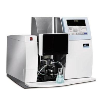
AAnalyst 200 Overview Figure 4- 1 The AAnalyst 200 Instrument The AAnalyst 200 Atomic Absorption Spectrometer is a double-beam atomic absorption spectrometer for flame and mercury/hydride analysis. It is a sophisticated analytical system capable of performing automated single element determinations. -
Page 71: The Aanalyst 200 Spectrometer System
AAnalyst 200 User’s Guide The AAnalyst 200 Spectrometer System Concept The AAnalyst 200 spectrometer from PerkinElmer is a compact benchtop flame atomic absorption spectrometer featuring: • Double beam optical system optimized for maximum radiation throughput. • Burner system for flame atomization. -
Page 72: General Lamp Information
System Description General Lamp Information There are a number of different lamps that can be used with the AAnalyst 200 instrument: the Lumina Hollow Cathode Lamp (HCL) and the Electrodeless Discharge Lamp (EDL) (coded and non-coded). The Intensitron Hollow Cathode Lamp (coded and non-coded), when used with an adapter, will function on the AAnalyst 200 instrument. - Page 73 AAnalyst 200 User’s Guide Hollow cathode lamps emit light by the following process: the fill gas is ionized when an electrical potential is applied between the anode and the cathode. The positively charged ions collide with the negatively charged cathode and dislodge individual metal atoms in a process known as “sputtering.”...
- Page 74 System Description If you have a coded Intensitron HCL, there is a universal adapter cable (N305-0196) to be used with the lamp. However, lamp coding is lost, therefore lamp and element parameters must be set manually when coded HCLs and universal adapter cables are used. Intensitron Hollow Cathode Lamp...
- Page 75 AAnalyst 200 User’s Guide Electrodeless Discharge Lamps (EDL System II) While hollow cathode lamps are an ideal source for determining most elements by atomic absorption, for volatile elements, an electrodeless discharge lamp (EDL) is recommended instead. EDLs provide greater light output for improved detection limits and precision, along with increased sensitivity and working curve linearity.
- Page 76 AAnalyst instrument. Lamp Maintenance and Cleaning There are really no maintenance procedures for any of the PerkinElmer hollow cathode lamps. If you notice fingerprints on the “window” of your lamp, wipe them off with a soft, dry, lint free cloth.
-
Page 77: The Deuterium Arc Background Corrector
AAnalyst 200 User’s Guide The Deuterium Arc Background Corrector An Explanation: The Deuterium Arc Background Corrector The Deuterium Arc Background Corrector is an internally mounted assembly that provides correction for molecular absorption and light-scattering. The spectrometer uses a deuterium arc lamp to correct for background absorbance caused by non-atomic species in the atom cloud. -
Page 78: The Burner System
System Description The Burner System The burner system used in the spectrometer system is of the premix design. The measurement solution is sprayed by a pneumatic nebulizer into the burner chamber in the form of an aerosol. This aerosol is thoroughly premixed with the burner fuel and oxidant gases in the burner chamber. - Page 79 AAnalyst 200 User’s Guide How the Burner System Works The basic instrument includes a burner system for flame sampling operation. A system block diagram is shown in the next figure. As previously mentioned, the heat produced by the burner converts the sample into free atoms that can absorb the light from the source lamp for the element(s).
- Page 80 System Description Figure 4- 8 Block diagram of the complete burner system. 4-14...
- Page 81 AAnalyst 200 User’s Guide The Burner Head All the burner heads are made from titanium. The 10-cm, air-acetylene burner head is standard with the AAnalyst instruments. All the available burner heads are listed next in numerical order. • N040-0100: 5-cm, single-slot burner head (for nitrous oxide-acetylene operation).
- Page 82 System Description The Burner Mount The quick change burner mount provides horizontal, vertical, and rotational adjustment. The quick-disconnect release lever simplifies removal of the burner assembly. The Ignitor Assembly The ignitor assembly includes the glow plug, the ignitor solenoid and ignitor arm, the burner head interface circuit, and the flame detect circuit.
- Page 83 AAnalyst 200 User’s Guide Spiral Wrap Drain Interlock Cable Connector at Burner Interlock Cable Drain Tubing Retainer Cap Drain interlock Float Switch Assembly Drain Loop Waste Vessel Figure 4- 10 The burner drain system and its parts Burner Installation The entire installation of the burner is covered in Chapter 6, Operation of this User’s Guide Manual.
- Page 84 Burner System Troubleshooting We recommend that you consult the troubleshooting information included in this manual before you call a PerkinElmer service engineer. Refer to Chapter 10, Troubleshooting, for your burner system troubleshooting information. Included are suggestions to help you determine systematically whether instrument problems are due to improper analytical techniques, improper selection of instrument parameters, or a malfunction of the instrument.
-
Page 85: Connecting The Electrical Supply
In addition, the instrument consumes 300 volt amps (maximum) when configured for background correction. The AAnalyst 200 requires a grounded AC outlet providing voltage corresponding to the voltage range marked on the instrument (100-230 VAC). Do not remove or alter the ground prong on a three-prong power plug. - Page 86 System Description Installing the AC line Cord Grounding circuit continuity is vital for safe operation of equipment. Never operate equipment with grounding conductor disconnected. Do not remove or alter the ground pin on a three- prong line cord. WARNING The line cord should have the electrical rating and plug appropriate for your location. See the figure below for the correct cord.
-
Page 87: Mercury/Hydride Determination System (Mhs-15)
AAnalyst 200 User’s Guide Mercury/Hydride Determination System (MHS-15) Mercury/Hydride Systems are proven accessories for high sensitivity determinations of mercury and metallic hydride-forming elements, including As, Se, Sb, Te, Bi and Sn by atomic absorption spectroscopy. The basic components of a mercury/hydride system are the reaction vessel and sampling cell. The sample solution reacts with a reducing agent in the reaction vessel. - Page 88 System Description The MHS-15 is a manual system. The quartz cell is heated by the flame. Key operating parameters are controlled by the instrument touch screen. Data collection, calibration, and calculation functions are performed by the instrument. The MHS-15 analyzer assembly is freestanding and is located near the sample compartment of the spectrometer.
-
Page 89: Chapter 5 Installation
Installation... -
Page 91: Introduction To The Installation Procedure
AAnalyst 200 User’s Guide Introduction to the Installation Procedure Before you start to install your AAnalyst 200 spectrometer, please take time to read through this self- installation guide and become familiar with the steps involved. Please make sure your laboratory meets all of the requirements listed in this chapter, before you begin to install the system. -
Page 92: When The Spectrometer Arrives
Carefully read these instructions before you unpack the AAnalyst 200 to avoid damaging the instrument. The AAnalyst 200 is shipped in a single carton. The carton contains the instrument in the lower portion of the box with an inner tray designed to hold items in the upper portion of the box. The touch screen, atomizer compartment door, drain bottle, sample shelf, user guides, and small parts are contained in the inner tray. - Page 93 AAnalyst 200 User’s Guide Shipping Carton Top Molded Foam Padding Cardboard Boxed Items (as required) Carton Sleeve Shipping Carton Base Figure 5- 1Exploded view of the shipping carton...
-
Page 94: Placing The Spectrometer On The Bench
Installation Placing the Spectrometer on the Bench Risk of injury through lifting. The instrument weighs approximately 49 kg (108 lbs.).Improper lifting can cause painful and sometimes permanent back injury. Use proper lifting postures and/or mechanical lifting aids to lift or move the instrument. WARNING 1. - Page 95 AAnalyst 200 User’s Guide Carton recycling instructions The carton can be folded down for easy storage. You can store the carton for future use (to transport the instrument), or break it down completely and give it to your local recycling center.
-
Page 96: Aanalyst 200 Shipping List
Installation AAnalyst 200 Shipping List The following parts are included in the shipment. Table 5- 1 Shipping List Description AAnalyst 200 Instrument Burner Door (in a box) Touch Screen (in a box) Drain Assembly (including the drain vessel) Installation Kit (including the multimedia CD) -
Page 97: Aanalyst 200 Spares Kit
AAnalyst 200 User’s Guide AAnalyst 200 Spares Kit The following parts are included in the AAnalyst 200 Spares Kit (P/N B315-0021). The kit is shipped with the instrument. Table 5- 2 Spares Kit Part No. Description N315-0188 Nebulizer Kit B019-1060... -
Page 98: Installing The Touch Screen
Installation Installing the Touch Screen The touch screen is packed separately for shipping. To facilitate installation of the touch screen you must temporarily remove the lamp door. Figure 5- 3 Removing lamp door Remove the lamp door and install the touch screen Remove the lamp door 1. - Page 99 AAnalyst 200 User’s Guide Install the touch screen Figure 5- 4 Installing the touch screen Locate the touch screen (packed separately). 1. Thread the connector cord through the slot above the lamp compartment. Screen 5- 1 Slot above the lamp compartment...
- Page 100 Installation Slide the touch screen over the slot in the instrument cover and gently move into place. Screen 5- 2 Mounting the touch screen Locate the screw above the lamp compartment and tighten it. Screen 5- 3 Screw above the lamp compartment Thread the connector cord into the channel.
- Page 101 AAnalyst 200 User’s Guide 5. Connect the display cable to the E-Box’s Display Connector receptacle. E-Box Display Connector Screen 5- 5 E-Box 6. Remount the lamp door. This completes installation of the touch screen. You must calibrate the touch screen when you put the spectrometer into operation for the first time.
-
Page 102: Connecting The Gas Hoses
Installation Connecting the Gas Hoses Make sure your laboratory meets all of the requirements listed in Chapter 2, before you begin to install the system. Fittings suitable for most commonly available gas regulators are provided in the installation kit supplied with the spectrometer. - Page 103 Figure 5- 5Rear view of the spectrometer showing the gas hoses Connecting to the air supply Warning: Flashback Hazard PerkinElmer burner systems are designed for use with compressed air. The use of oxygen can cause an explosion in the burner system, and oxygen-enriched air WARNING can cause a flashback of the flame.
- Page 104 Installation Compression nut Air Supply Black air hose from spectrometer Air dryer filter assembly Figure 5- 6 Air supply connections showing air dryer filter assembly 1. Connect the black air hose (coming from the back of the spectrometer) to the outlet of the air dryer filter assembly.
- Page 105 AAnalyst 200 User’s Guide Connecting to the nitrous oxide supply Nitrous oxide regulator Compression nut Nitrous oxide cylinder Blue nitrous oxide hose from spectometer Figure 5- 7 Nitrous oxide supply connections 1. Connect the blue nitrous oxide hose (coming from the back of the spectrometer) to the nitrous oxide regulator.
- Page 106 Installation Connecting to the acetylene supply Warning: Flammable Gas – Fire and Explosion Hazard Acetylene is a flammable gas. The seepage of acetylene from any gas connection constitutes a serious fire hazard. Make sure that all gas connections WARNING are gas tight. Check the gas connections and gas hoses regularly for leaks using a suitable leak testing fluid.
-
Page 107: Setting Up The Burner System
AAnalyst 200 User’s Guide Setting up the Burner System Figure 5- 9 Full view of the AAnalyst 200 Instrument 5-19... - Page 108 Installation Install the Burner Assembly 1. Carefully remove the foam packing piece from around the burner system. 2. Guide the burner assembly into the tracks of the atomizer compartment. 3. Push the burner assembly in so that the rear gas fittings line up with the gas connectors at the back of the atomizer compartment.
-
Page 109: Installing The Burner Door
AAnalyst 200 User’s Guide Installing the Burner Door The burner door is packed separately for shipping. Refer to the figure below when installing the door. Burner Door Figure 5- 10 Installing the atomizer compartment door 1. Hold the door in place next to the burner compartment. -
Page 110: Installing The Sample Tray
NOTE: Do not block access to the E-Box located behind the right front cover. Removal of the power cord from the appliance coupler will completely disconnect the AAnalyst 200 from AC power line. This completes the procedure for installing the sample tray. -
Page 111: Connecting To The Electrical Supply
1. Check the line cord provided with the spectrometer to make sure that it is fitted with the correct plug for your location. If the plug is not correct, contact your local PerkinElmer office for advice. 2. Make sure that the On/Off switch on the spectrometer’s E-Box (behind the lamp door) is in the Off position (depressed). -
Page 112: Switches And Connectors On The E-Box
Installation Switches and Connectors on the E-Box All electronics are located in a single user-replaceable module called the E-Box. Switches and connector ports are located on the front panel of the E-Box as shown in the figure below. Remote Trigger Ethernet Printer Keyboard... -
Page 113: Setting Up The Autosampler
AAnalyst 200 User’s Guide Setting Up the AutoSampler The AA200 Analyst supports autosampler model AS-90, AS-90 plus (p/n B314-0291), and AS-93 plus (p/n B314-0330). Depending on your autosampler model, refer to the User’s Guide provided with your autosampler for complete installation. -
Page 114: Connecting The Foot Switch
Installation Connecting the Foot Switch The AA200 Analyst supports the foot switch (p/n 0999-8306). The foot switch is an optional feature that allows the user to conveniently analyze samples without touching the analyze button on the touchscreen. The user simply steps on the foot switch and starts analyzing sample. Electrical connections Connecting foot switch (p/n 0999-8306) to the E-Box: 1. - Page 115 Operation of the Instrument...
-
Page 117: Starting Up The System
AAnalyst 200 User’s Guide Starting up the System Summary of the procedure Read the safety information at the front of this guide before you operate the system. 1. Make sure that the spectrometer system and other ancillary instruments are correctly installed and connected to their AC line power outlets. - Page 118 Operation of the Instrument • Only high quality purge gases (Air, Ar or N ) should be used. Minimum purity of 99.9% is recommended. A high quality filter-dryer accessory is recommended for the removal of any moisture from the purge gas. Warning: Acetylene –Explosion Hazard Acetylene can decompose explosively at pressures higher than 103 kpa/1.03 bar/ 15 psig.
-
Page 119: Setting Up The Burner System
AAnalyst 200 User’s Guide Setting up the Burner System Summary of the procedure 1. Check that the drain trap is filled with water. 2. Install the correct burner head for the type of flame that you intend to use – air-acetylene (10 cm) or nitrous oxide-acetylene (5 cm). - Page 120 Operation of the Instrument Assembling the Quick-Change Burner Mount Assembly Before the burner assembly can be put into the instrument, a few items need to be added or checked. The following sections give full procedures to do so. Installing the Nebulizer on the Burner Refer to the figure below to install the nebulizer onto the burner end cap.
- Page 121 AAnalyst 200 User’s Guide 4. Lower the nebulizer clamp until it presses against the barrel and flange of the nebulizer (shaded area). Ensure that the nebulizer is pushed in all the way and clamped in correctly. Warning, the nebulizer clamp must be lowered and locked OVER the nebulizer flange. Detail B shows the clamp lowered and locked correctly over the nebulizer flange.
- Page 122 Operation of the Instrument Checking that the Burner End Cap is Secure The burner end cap is assembled to the burner chamber at the factory. It is always a good idea to confirm that the screws are tight. To do so, hand-tighten (in an alternating pattern) the four knurled screws holding the burner end cap to the burner chamber.
- Page 123 AAnalyst 200 User’s Guide Connecting and Securing the Gas Hoses to the Burner There are three gas hoses that are connected to the end cap on the burner assembly: the nebulizer oxidant hose, the auxiliary oxidant hose, and the fuel hose. They are pointed out in the next figure. At this point, all three hoses should be already connected to the burner.
- Page 124 Operation of the Instrument Installing and Securing the Burner Head The burner head is shipped from the factory already attached to the burner assembly (10 cm air/acetylene N040-0102). If it was removed or you need to change it, follow these instructions to put it back on. Make sure the magnetic strip is facing the ignitor box.
-
Page 125: Installing Solvent-Resistant Components In The Burner
AAnalyst 200 User’s Guide Installing Solvent-Resistant Components in the Burner Warning: Flammable Gases – Fire and Explosion Hazard Not all gaskets in the burner unit are suitable for use with organic solvents. Exposure to such solvents may cause the respective gaskets to swell. This may WARNING result in a seepage of gas which is a serious fire hazard. - Page 126 Operation of the Instrument Installing the Burner Mount Assembly Figure 6- 6 Installing the burner mount assembly. 6-12...
- Page 127 AAnalyst 200 User’s Guide 1. Orient the assembly to slide into the tracks as shown in the figure above. 2. Slide the assembly (along the tracks) into place in front of the instrument. When the assembly is pushed all the way in, you will hear a “clicking” sound as the three fittings seat themselves and lock into the back of the sample compartment.
- Page 128 Operation of the Instrument Installing the Burner Drain System Locate and unpack the drain system from the shipping carton. It includes all the parts marked in the figure below. Connecting the Burner Drain System 1. Refer to the next figure when installing the drain system. Position the vessel on the floor underneath the front of the instrument and attach the retainer cap assembly (cap, trap and loop) to the drain vessel.
- Page 129 AAnalyst 200 User’s Guide Spiral Wrap Drain Interlock Cable Connector at Burner Interlock Cable Drain Tubing Retainer Cap Drain interlock Float Switch Assembly Drain Loop Waste Vessel Figure 6- 7 Installing the burner drain system 6-15...
- Page 130 Operation of the Instrument 3. Now attach the free end of the drain tubing outlet on the burner end cap. Tighten the drain clamp. Figure 6- 8 Connecting the drain tubing and drain interlock cable. 4. Finally, you need to connect the drain interlock cable. Plug the drain interlock connector into the drain interlock plug located on the burner assembly as shown above.
- Page 131 AAnalyst 200 User’s Guide Adding water to the Drain Float Assembly Enough water must be present in the drain system to fill the drain loop and to activate the drain float assembly. If not, carry out the procedure below: 1. Loosen the drain clamp and remove the drain tubing from the drain outlet on the burner end cap (see Figure 6- 8).
- Page 132 Operation of the Instrument Figure 6- 9 Installing the lamp compartment cover. 6-18...
-
Page 133: User Interface
AAnalyst 200 User’s Guide User Interface Screen 6- 1 Typical Touch Screen Display Touch screen You operate the spectrometer using the touch screen. The touch screen is the interface between you and the spectrometer, enabling you to control the spectrometer in order to perform your analyses easily and conveniently. - Page 134 Operation of the Instrument User interface components The user interface components on the touch screen are described below. Pages The main displays on the touch screen are termed pages. You use the pages to set up your spectrometer and to perform analyses. The pages contain •...
-
Page 135: Installing Lamps
Installing Lamps Three versions of the AAnalyst 200 spectrometer are offered. • The first version is designed to operate with a single PerkinElmer Lumina hollow cathode lamp (HCL). • The second version is designed to operate with a single PerkinElmer Lumina hollow cathode lamp (HCL) or an electrodeless discharge lamp (EDL). - Page 136 Operation of the Instrument Installing and connecting HCLs You can use both single-element and multi-element hollow cathode lamps. Figure 6- 11 Installing a hollow cathode lamp 1. Open the lamp door. 2. Slide the required Lumina lamp into the lamp holder and make sure that the integrated socket slides fully home over the receptacle on the lamp holder.
- Page 137 AAnalyst 200 User’s Guide 3. Slide the lamp carefully into the lamp holder until it butts up against the end stop inside the holder. 4. Connect the lamp cable to an EDL 1 port on the E-Box. Align the lamp.
- Page 138 7. Unplug and remove the lamp. For EDLs, remove the coding plug as well. Tips for installing lamps • Use PerkinElmer lamps. • Do not touch the front window of the lamp: perspiration or other contamination can reduce intensity of the radiation.
-
Page 139: Switching On The Spectrometer
AAnalyst 200 User’s Guide Switching on the Spectrometer Figure 6- 13 Location of operational on/off switch 1. Open the lamp door. 2. Switch on the spectrometer with the operational on/off switch. 3. Close the lamp door. 4. Wait for the spectrometer to complete initialization. The Lamp page is displayed on the Touch Screen. -
Page 140: Safety Checks
Operation of the Instrument Safety Checks Before igniting the flame, always make sure that: • The exhaust venting system for the laboratory is switched on. • Burner chamber is correctly installed. • The burner head is correctly installed. • The burner end cap is secured. •... -
Page 141: Using The Background Corrector
AAnalyst 200 User’s Guide Using the Background Corrector If you have a deuterium background corrector in your AAnalyst 200, you have the choice of performing atomic absorption measurements with or without background correction. It is an internally mounted assembly that provides simultaneous correction for molecular absorption and light-scattering. -
Page 142: Optimization Procedures
Operation of the Instrument Optimization Procedures Before you calibrate the spectrometer and begin analyses, you must optimize the spectrometer to obtain the best conditions for analyzing the requested element in your samples. You can optimize: • The lamp: You must align the lamp in the optical path so that maximum radiant energy passes to the detector. -
Page 143: Aligning Lamp
AAnalyst 200 User’s Guide Aligning Lamp After you have installed the lamp you require for your planned analyses, you must align it in the optical path so that maximum radiant energy passes to the detector. In a single lamp configuration, you must manually align the lamp position by using the adjustable knobs as shown in the figure below. - Page 144 Operation of the Instrument Align the lamp NOTE: For lamp optimum performance, warm HCLs for 5-10 minutes and 30 minutes for EDLs. Repeat the lamp setup procedure. Coded single element Lumina lamp 1. Start up the spectrometer, but do not ignite the flame. 2.
- Page 145 AAnalyst 200 User’s Guide 5. Touch the On/Off check box. If necessary, change the lamp current. Touch OK. 6. Touch the Element entry field box to select the desired element. Touch OK. 7. Touch the Setup Instrument button on the Lamp page of the touch screen. The recommended parameters for that element are automatically set up.
- Page 146 Operation of the Instrument Turret uncoded Lumina lamp (mount) 1. Start up the spectrometer, but do not ignite the flame. 2. Touch the Install Lamps button on the Lamp page of the touch screen. Fill in the required parameters for the uncoded lamps in the Install Lamps dialog. 3.
-
Page 147: Setting The Burner Height
AAnalyst 200 User’s Guide Setting the Burner Height When you operate the spectrometer for the first time and every time you have disassembled the burner for cleaning, you must check and set the burner height. You must perform this procedure to make sure that the burner head is located just below the radiation beam. - Page 148 Operation of the Instrument Figure 6- 17 Burner alignment controls 1. Touch the Flame tab to display the Flame page. 2. Lower the burner with the vertical alignment control so that the burner head is well below the radiation beam. 3.
-
Page 149: Igniting The Flame
AAnalyst 200 User’s Guide Igniting the Flame Warning: Flammable Gases, Fire and Explosion Hazard Β efore you ignite the flame, setup your spectrometer and burner correctly and observe all the safety precautions described in your spectrometer guide. WARNING Warning: UV Radiation Risk of Eye Damage The flame, especially the nitrous oxide-acetylene flame, may emit UV radiation which can damage your eyes. - Page 150 Operation of the Instrument 7. Ignite the flame: Touch the On side of the Flame On/Off switch. The indicator in the switch lights up. 8. The correct procedure to extinguish the flame is described in this chapter. 9. If the system is set up correctly the flame is ignited using default values for the gas flows. If you selected nitrous oxide as the flame type, the flame is ignited with an air-acetylene mixture, with automatic changeover to nitrous oxide after several seconds.
-
Page 151: Preadjusting The Nebulizer
AAnalyst 200 User’s Guide Preadjusting the Nebulizer In this procedure you adjust the aspiration rate (solution uptake rate) of the nebulizer. You must preadjust the nebulizer whenever you install a nebulizer or when you have partially or totally dismantled the nebulizer for any reason, such as cleaning. - Page 152 Operation of the Instrument Preadjustment procedure 1. Touch the Flame tab to display the Flame page. 2. Aspirate the blank solution and when the signal is steady touch the Auto Zero Graph button. 3. Aspirate the standard solution. 4. Turn the nebulizer regulator slowly counter-clockwise until bubbles start to appear from the end of the sample tube in the standard solution.
-
Page 153: Optimizing The Burner System
AAnalyst 200 User’s Guide Optimizing the Burner System Summary of the optimization procedure 1. Perform the preliminary steps. 2. Prepare the required solutions. 3. Install a lamp for the analyte element. 4. Start up the spectrometer. 5. Set up the burner system. - Page 154 Operation of the Instrument Optimizing the burner position 1. Touch the Flame tab to display the Flame page. 2. Aspirate the blank solution and when the signal is steady touch the Auto Zero Graph button. 3. Aspirate the standard solution. 4.
- Page 155 AAnalyst 200 User’s Guide Optimizing the gas flows The oxidant-to-fuel ratio affects the sensitivity of the analyses, although the magnitude of the effect varies between elements. Generally you adjust the gas flow rates to give maximum absorbance for the analyte element.
- Page 156 Operation of the Instrument There are two ways to alter the gas flow rates while you are performing the optimization procedure: • Touch the flow field to display the Flow dialog and then enter the required flow rate in this dialog.
-
Page 157: Rinsing The Burner System
AAnalyst 200 User’s Guide Rinsing the Burner System Before you extinguish the flame or begin maintenance or disassembly procedures, you must rinse the burner system. After you extinguish the flame, allow the burner head to cool. To rinse the system The procedure for rinsing the burner system depends on the type of samples that you have analyzed. - Page 158 Operation of the Instrument 6-44...
- Page 159 Touch Screens...
-
Page 161: Chapter 7 Touch Screen
The touch screen contains active areas that you touch to perform the required action. Only use the stylus provide with your AAnalyst 200 to touch the active areas of the touch screen. Do not use sharp, pointed objects. - Page 162 Touch Screens User interface components The user interface components on the touch screen are described below. Pages The main displays on the touch screen are termed pages. You use the pages to set up your spectrometer and to perform analyses. The pages contain •...
-
Page 163: Startup Dialog
AAnalyst 200 User’s Guide Startup Dialog The following page is the first page displayed once you start up the system. You use this page to select the technique (Flame or MHS) and to examine the system diagnostics. Touch the Details bar on the screen to get details on the Power-on Diagnostics. In the Details dialog all entries should be in green to indicate that all systems are OK. -
Page 164: Lamp Page
Touch Screens Lamp Page You use this page to select the analyte element and the basic measurement parameters. You also use this page during optimization to align the lamp with systems utilizing manual lamp adjustment. Screen 7- 3 Lamp Setup Page... - Page 165 AAnalyst 200 User’s Guide Parameters on Lamp page Displays the current active signal. Signal Touch-entry field that displays the mode of signal measurement selected for the analysis. You can touch this field to display the Signal dialog. In this dialog you can choose:...
- Page 166 Touch Screens desired wavelength. Displays the current active slit. The slit width and height provides the Slit (nm) optimum sensitivity, the best signal-to-noise ratio and good linearity of the calibration curve at the recommended wavelength. Touch-entry field that displays the spectral width and height of the slit selected to measure the absorption.
- Page 167 AAnalyst 200 User’s Guide Parameters on Install Lamps dialog Lamps can be turned on or off by using the touch-entry On/Off field box to check/ uncheck lamps and touch the OK button. Coded lamps – the instrument detects the element(s) Elements and automatically fills the Elements entry box.
- Page 168 Touch Screens • For an uncoded lamp, you must complete the following entries: Element, Lamp Type, and current. The Wavelength and Slit Width are automatically filled in after entering the element symbol. Coded Lamp Single-Element Coded Lamp 1. If you installed a single-element coded lamp, the analyte appears automatically in the element entry-field box.
-
Page 169: Flame Page
AAnalyst 200 User’s Guide Flame page You use this page to select the oxidant and other flame parameters, and to ignite the flame. You also use this page during optimization of the burner system and to view continuous graphical absorbance display. - Page 170 Touch Screens Continuous Graphics Window on the Flame page The Continuous Graphics window contains a continuous, real-time plot of absorbance (or emission) against time. The scale for Y-axis and real time absorbance default value ranges from 0.00 - 4.00 absorbance. Parameters on Flame page Touch-entry field that displays the selected oxidant: Oxidant...
- Page 171 AAnalyst 200 User’s Guide Buttons on Flame page Touch the On side of this ‘switch’ to ignite the flame. Flame On/Off Touch the Off side of this ‘switch’ to extinguish the flame. In an emergency, press the Red Emergency button located on the upper left side of the instrument.
-
Page 172: Parameters Page
Touch Screens Parameters Page You enter the analytical parameters on the Parameters page. This page comprises two subpages: • Spectrometer subpage • Calibration subpage Spectrometer subpage You enter spectrometer-related parameters on this page. This is always the first page shown when you touch the Parameters tab. - Page 173 AAnalyst 200 User’s Guide Screen 7- 10 Spectrometer Subpage, Flame Technique 7-15...
- Page 174 Touch Screens Items on this page Touch-entry field that displays the selected integration time. This is Integration Time the time period over which the spectrometer takes a measurement. The (sec) longer the time, the greater is the level of signal integration. To change the integration time, touch this field to display the number pad dialog.
- Page 175 AAnalyst 200 User’s Guide Calibration subpage 1. Touch the Calibration tab to display this subpage. 2. You select the required calibration equation units and enter the concentrations of the standards (calibration solutions) on this page. Screen 7- 11 Calibration Subpage...
- Page 176 Touch Screens Standard Concentrations Touch-entry fields that display the selected concentrations of up 1 – 8 to 8 standards (calibration solutions). To enter the concentration of a standard, touch the required field to display the Standard Conc. dialog. Enter the required concentration and then touch OK.
- Page 177 AAnalyst 200 User’s Guide sample is calibrated individually. A calibration curve defined using this equation is forced to pass through zero absorbance and zero concentration (i.e. the origin). You can select the technique of addition calibration when the matrix Analyte Addition...
-
Page 178: Analyze Page: Manual Data Display
Touch Screens Analyze Page: Manual Data Display This window allows users to manually analyze a solution and view the results in the Result Window that appears on the Analyze Sample Page. When the system finishes the analysis of each solution, data will appear at the bottom of the scrolling display as it is generated and the user will have the option of scrolling backward to review previous data. - Page 179 AAnalyst 200 User’s Guide Screen 7- 13 Analyze Samples Page: Manual Data Display, MHS Technique Results Window on the Sample Page This window displays the standards and sample measurements. This displays specific sample identifier about each Sample solution analyzed. For example: blank, standard 1, standard 2, sample 1, sample 2, etc.
- Page 180 Touch Screens Buttons on Analyze Samples page To analyze the blank defined in the method, touch this Analyze Blank button. A green light appears on this button when selected. To analyze the standard indicated in the standard Analyze Standard concentration box, touch this button. A green light appears on the button when selected.
-
Page 181: Analyze Samples Page: Manual Continuous Display
AAnalyst 200 User’s Guide Analyze Samples Page: Manual Continuous Display This window displays the continuous graphics at the top of the screen. The display contains a continuous, real time plot and a numerical reading for the signal. The plot and the numerical value are continuously updated to the current reading. - Page 182 Touch Screens Buttons on Analyze page To analyze the blank defined in the method, touch this button. Analyze Blank A green light appears on this button when selected. To analyze the standard indicated in the Standard Analyze Standard Concentration Box, touch this button. A green light appears on the button when selected.
-
Page 183: Analyze Page: Autosampler
AAnalyst 200 User’s Guide Analyze Page: Autosampler This window allows users to setup and perform automated analyses. Results of each analysis are displayed on the Results Window. When the system finishes the analysis of each solution, the most recent results are added to the bottom of the Results Window. - Page 184 Touch Screens referred to as the coefficient of variation. This displays the replicate information for each Replicates replicate analyzed. Buttons on Analyze Samples page By touching this button, the system will start an Analyze All automated analysis of the blank, standards, and samples.
-
Page 185: Tools Dialog
AAnalyst 200 User’s Guide Tools Dialog You can access the Tools dialog by touching the blue Tools… button located on the bottom of the touchscreen. This dialog is a collection of function and utility buttons. Screen 7- 16 Tools Dialog Buttons on Tools Touch this button to open a dialog of stored methods. - Page 186 Touch Screens This button displays the diagnostic dialog, used to make sure that Diagnostics your instrument and its accessories have been installed properly and are functioning properly. This button displays the Recommended Conditions dialog, which Recommended shows recommended analytical conditions for determining the active Conditions element.
- Page 187 AAnalyst 200 User’s Guide Screen 7- 17 Sample Information Dialog Buttons on Sample Information Dialog Sample Number The range of sample numbers being displayed (10 at a time in the table) can be changed by using the scroll bar. A maximum of 250 samples can be displayed.
- Page 188 Touch Screens OK button Use this button to close the dialog. Changes made cannot be cancelled. New button Click on this button and the message do you really want to do this appears. If you click OK, the sample information will be cleared. Open button Click on this button to opens the Open Sample Information, where you can open a stored sample information file.
-
Page 189: Recommended Conditions
AAnalyst 200 User’s Guide Recommended Conditions You use this page to show the recommended analytical conditions for determinations using the flame technique. The analytical conditions shown can often be used to produce acceptable results for determining elements in samples with a simple matrix. -
Page 190: Network Dialog
Touch Screens Network Dialog AAnalyst 200 data can be saved to a stand-alone computer or to a network computer using a LAN connection. Once a network connection is established, all the analyses result data will automatically be saved. To establish connection between a stand-alone computer and the AA200 instrument, follow the procedure below. - Page 191 AAnalyst 200 User’s Guide Network Setup 5. In the Network Setup section of the Network dialog, choose Specify an IP address option. Enter the suggested IP Address and Subnet Mask below. • IP Address – 10.0.0.1 • Subnet Mask – 255.255.255.0 NOTE: Entries for Default Gateway are not needed for a stand-alone computer.
- Page 192 Touch Screens Screen 7- 21 System Properties 7. Share Name – A name of a drive or folder on the directory that allows other users permission to access it. If you do not already have an existing shared drive or folder and need to create a shared drive or folder, follow the procedure below.
- Page 193 AAnalyst 200 User’s Guide Screen 7- 22 Shortcut menu • Properties folder appear and select Share this folder option. 7-35...
- Page 194 Touch Screens Screen 7- 23 Properties dialog • Click the Permissions button to set users permissions to the shared drive or folder. 7-36...
- Page 195 AAnalyst 200 User’s Guide Screen 7- 24 Permissions dialog • Click OK and the desired drive/ folder is now shared. Screen 7- 25 Shared folder 8. User Name and Password – Enter the user’s name and password in the Network dialog.
- Page 196 Touch Screens • Fill in the dialog completely giving the User Name, Full Name, Description, Password, and password options. Screen 7- 26 New User dialog NOTE: It is suggested that the "User must change password at next logon" is selected as the password option.
- Page 197 AAnalyst 200 User’s Guide To set permissions for the AA200 Result Data directory: • From the C:\ directory, right mouse click on the AA200 Result Data folder. • Select Properties. • Click on the Security Tab. • Deselect Allow inheritable permissions from parent to propagate to this object.
- Page 198 • Enter the Instrument ID in the entry field box. NOTE: Each AAnalyst 200 instrument must have a unique ID. For example, AA200_1, 1 is the ID number for AA200 instrument 1. The ID can range from 0-255. For Static IP Network, do the following: •...
-
Page 199: Download
AAnalyst 200 User’s Guide Download To download new software/ firmware, it is necessary to first establish a connection between a computer and the AA200 instrument using Microsoft ActiveSync program. Download Requirement • Computer running Windows NT, 2000, or XP. •... - Page 200 Touch Screens 3. Pause at the Get Connected window and physically connect the RS 232 serial cable from the E-Box to the computer. • Connect RS 232 serial cable to the serial 1 of the E-Box. • From the E-Box, run the RS 232 serial cable to the comport 1, 2, 3, or 4 of the computer. Screen 7- 29 Get Connected Window 4.
- Page 201 AAnalyst 200 User’s Guide Screen 7- 30 Tools Dialog from the Touch Screen 5. Touch the Download button from the Tools dialog to start the download. 6. Continue from the Get Connected window and click Next. 7. If the Partnership dialog appears, select the No option button and then click Next.
- Page 202 3. The command prompt window appears and the download of the software/ firmware to the E- Box begins. 4. A successful download will display ‘Download is Completed’ on the command prompt. 5. Reboot the AAnalyst 200 instrument by powering it down and back up. 7-44...
- Page 203 4. Timing is crucial: just as the arrow appears, use the keyboard to press the ESC key continuously until a blue PerkinElmer Instrument screen appears on the touch screen. NOTE : Press CTRL + ESC key to display the Start menu.
- Page 204 Touch Screens Screen 7- 34 Run Dialog 9. Follow steps 7-10 from the Connection Setup procedure. 10. Follow steps 1-4 of the Downloading procedure. 11. Reboot the AA200 instrument. 7-46...
-
Page 205: Importing Aanalyst 200 Into Microsoft Excel
1. Insert the AAnalyst 200 Quick Start CD into the CD-ROM drive. 2. In the Main menu of the AAnalyst 200 Quick Start program, click on Quit in the lower right part of the window. This will exit the AAnalyst 200 Quick Start program. - Page 206 Touch Screens 8. Power on the AAnalyst 200 (if it is not already on). 9. On the AAnalyst 200 touch screen, touch the Tools… button to access the Tools dialog. 10. From the Tools dialog, touch the Download button. Screen 7- 36 Tools Dialog from the Touch Screen 11.
- Page 207 Screen 7- 37 New Partnership Dialog 13. When the ActiveSync window appears on the screen, click the Explore icon. A window appears displaying thumbnails of files and folders stored on the AAnalyst 200. Screen 7- 38 The Microsoft ActiveSync window shows the connection 14.
- Page 208 Touch Screens 17. Launch Microsoft Excel and select Open from the File menu. Navigate through the Open dialog folder to search and open results.dat file that was previously copied to the desired directory. 18. When the Excel Text Import Wizard window appears, select the Delimited option and click Next.
- Page 209 AAnalyst 200 User’s Guide Screen 7- 41 Test Import Wizard, Step 3 21. Select Save As from the File menu to save your result as an excel file. 7-51...
- Page 210 Touch Screens 7-52...
-
Page 211: Chapter 8 Analyzing Samples
Analyzing Samples... -
Page 213: Sequence Of Operations
AAnalyst 200 User’s Guide Sequence of Operations The diagram below shows the sequence of operations that you must perform to analyze samples using the AAnalyst 200 spectrometer. The pages and dialogs that you require for each step are shown. Lamp... -
Page 214: Manual Flame Analyses
Analyzing Samples Manual Flame Analyses Overview Once the system has been powered up and optimized, analyzing samples is simply a matter of entering parameters, then aspirating solutions of a blank, standards, and samples. The AAnalyst 200 has the capability to use up to eight calibration standards and a choice of calibration equations. - Page 215 AAnalyst 200 User’s Guide Analyzing Samples using Linear/ Non-Linear Calibration The following example describes how to run samples using the linear calibration technique. It should be noted that the same steps are carried out when using the nonlinear calibration technique. The only difference is in setting up the calibration type. Instead of selecting linear for the calibration type, you select nonlinear.
- Page 216 Analyzing Samples Table 8- 1 Suggested Standards Element Standard 1 Standard 2 Standard 3 Reslope (mg/L) (mg/L) (mg/L) (mg/L) 0.05 3. For samples 1, 2 and 3, use Standards 1, 2, and 3, respectively, in this example. Data Display If you selected Manual Data Display for Sample Handling on Spectrometer subpage, continue as described in this section.
- Page 217 AAnalyst 200 User’s Guide On Parameters page, Spectrometer subpage: 1. Enter 1 second for the Integration Time. 2. Enter 3 for the number of Replicates. 3. Enter 5 seconds for the Read Delay. 4. Enter the required Print parameters. 5. Select Manual Data Display for Sample Handling.
- Page 218 Analyzing Samples • Enter the concentration of the Reslope standard (e.g., 1.0 mg/L for copper). Parameter entry is now complete. Proceed to the next step. Screen 8- 2 Parameters page, Calibration subpage. Analyze samples As measurements are made, the results appear on the analyze screen. You may view the calibration curve of the analyses at anytime by touching the display calibration button.
- Page 219 AAnalyst 200 User’s Guide NOTE: After a standard is analyzed, the next standard concentration is automatically incremented in the standard entry-field box. You have the option of using the automatically filled entry or you may select a different standard concentration to be analyzed by using the standard touch entry-field box.
- Page 220 Analyzing Samples Screen 8- 4 Display Calibration screen 8-10...
- Page 221 AAnalyst 200 User’s Guide Continuous Display If you selected Manual Continuous Graphic Display for Sample Handling on Spectrometer subpage, continue as described in this section. Enter parameters on Lamp page 1. If not already done, install and align the required lamp. For more information see Chapter 6, Operation of the Instrument.
- Page 222 Analyzing Samples Screen 8- 5 Parameter page, Spectrometer subpage. On Parameters page, Calibration subpage: Select the Calibration Equation. 1. For this example select Linear Through Zero. Enter mg/L for Units. On Parameters page, Calibration subpage, Standard Concentrations section: 1. Enter the concentration of the first standard for the element that you are determining (e.g., 0.5 for copper).
- Page 223 AAnalyst 200 User’s Guide Screen 8- 6 Parameter page, Calibration subpage. Parameter entry is now complete. Proceed to the next step. Analyze samples As measurements are made, the results appear on the Analyze screen. You may view the calibration curve of the analyses at anytime by touching the calibration curve button.
- Page 224 Analyzing Samples • Touch the Analyze tab to display the Analyze page. • Touch the Printer button if you wish the results to be printed. NOTE: Check printer function, the printer already maybe on. 1. Aspirate the blank 2. Touch Analyze Blank button. 3.
-
Page 225: Automated Flame Analyses
The AAnalyst 200 has the capability to use up to eight calibration standards and a choice of calibration equations. An example of an aspirating sequence for linear/ nonlinear... - Page 226 Analyzing Samples Analyzing Samples Using Linear Calibration The following example describes how to run samples using the linear calibration technique. It should be noted that the same steps are carried out when using the nonlinear calibration technique. The only difference is in setting up the calibration type. Instead of selecting nonlinear for the calibration type, you select nonlinear.
- Page 227 AAnalyst 200 User’s Guide Table 8- 2 Suggested Standards Element Standard 1 Standard 2 Standard 3 Reslope (mg/L) (mg/L) (mg/L) (mg/L) 0.05 3. For samples 1, 2 and 3, use Standards 1, 2, and 3, respectively. Set up the autosampler The autosampler you intend to use must be connected to the spectrometer.
- Page 228 Analyzing Samples 5. Select the information you would like to have printed together with the analytical results. 6. Select Autosampler for Sample Handling. Screen 8- 9 Parameters page, Spectrometer subpage. On Parameters page, Calibration subpage: 1. Select the Calibration Equation. 2.
- Page 229 AAnalyst 200 User’s Guide Screen 8- 10 Parameters page, Calibration subpage. Parameter entry is now complete on the Parameter page. At this point, the autosampler tray should be filled with blank, standards, and samples. All of the parameter entries on the Analyze page should be completed by now.
- Page 230 Analyzing Samples Screen 8- 11 Display Calibration screen. When you are satisfied with your calibration curve you may proceed to the next step. Analyze Samples Use this step to analyze samples only. 1. Touch the Analyze Samples button to begin analyzing samples. A green light indicates that it has started.
- Page 231 AAnalyst 200 User’s Guide The results are displayed and printed. Screen 8- 12 Analyze page 8-21...
-
Page 232: Manual Analyses: Data Display Mhs-Technique
Analyzing Samples Manual Analyses: Data Display MHS-Technique If you have selected MHS technique from the Startup dialog, continue as described in this chapter. Setting Up MHS-15 Analyses 1. Read the safety information in the handbooks for your system before you operate the spectrometer. -
Page 233: Running Samples In Emission Mode
AAnalyst 200 User’s Guide Running Samples in Emission Mode The AAnalyst 200 also performs flame emission measurements at a fixed wavelength. This option is useful when you do not have a lamp for the element you wish to determine or if you are determining elements such as Na, K, Ca, or Ba, which are sensitively determined by emission. - Page 234 Analyzing Samples Screen 8- 14 Lamp page, Startup Dialog. 5. To change the signal, touch the Signal field on the Lamp page. A Signals dialog will appear. 8-24...
- Page 235 AAnalyst 200 User’s Guide Screen 8-15 Lamp page. 6. In the Signals dialog touch the Flame Emission radio button to change the signal to Flame Emission. Touch the OK button to close this dialog box. Once the dialog box closes the element field will become blank.
- Page 236 Analyzing Samples Screen 8-16 Lamp page, Signal Dialog. 7. Complete the Flame page. Enter the required flame type, the oxidant and acetylene flow for the element to be analyzed. 8-26...
- Page 237 AAnalyst 200 User’s Guide Screen 8-17 Flame page. 8. Select the Parameters page, Spectrometer tab. Use the appropriate values to fill in the settings. 8-27...
- Page 238 Analyzing Samples Screen 8-18 Parameters page, Spectrometer tab. 9. Select the Parameters page, Calibration tab. In the Calibration Equation field touch the screen to access the dialog. 8-28...
- Page 239 AAnalyst 200 User’s Guide Screen 8-19 Parameters page, Calibration tab. 10. In the Calibration Equation dialog touch the appropriate calibration equation radio button to change the calibration equation. Touch the OK button to close this dialog box. NOTE: In the Calibration Equation window “Linear Through Zero” is the default choice for Flame Emission.
- Page 240 Analyzing Samples Screen 8-20 Parameters page, Calibration tab. 11. Go to the Analyze Sample page to start the analysis. Touch the Analyze Blank, Standard or Sample bar to begin the analysis. If printed results are needed touch the Printer On/Off bar to print the results.
-
Page 241: Shutting Down The System
AAnalyst 200 User’s Guide Shutting Down The System NOTE: In an emergency, switch off the spectrometer using the operational on/off switch behind the front door or use the emergency flame off switch (see page 8-32). The flame is automatically extinguished and the gases shut down in a safe sequence. -
Page 242: Emergency Shutdown
Analyzing Samples Emergency Shutdown If a situation arises where you have to shut down the system quickly and you do not have time to carry out the correct procedure, you can use the procedure described below. NOTE: This procedure is for use in an emergency only. Do not use it as a routine shutdown procedure. 1. -
Page 243: Rinsing The Burner System
AAnalyst 200 User’s Guide Rinsing the Burner System Before you extinguish the flame or begin maintenance or disassembly procedures, you must rinse the burner system. To rinse the system The procedure for rinsing the burner system depends on the type of samples that you have analyzed. - Page 244 Analyzing Samples 8-34...
-
Page 245: Chapter 9 Maintenance
Maintenance... -
Page 247: Introduction
You should perform only the maintenance procedures described in this chapter. If additional maintenance is required, contact a PerkinElmer Service Engineer. Before using any cleaning or decontamination methods except those specified by... -
Page 248: General Maintenance Checklist
Maintenance General Maintenance Checklist The following checklist describes general maintenance procedures. • For safety reasons, and to avoid contaminating new samples, you should ensure that the work area is kept absolutely clean. This is especially important when working with toxic substances and when measuring trace amounts of any elements. -
Page 249: Instrument Maintenance Checklist
Normally, the spectrometer optics will require little or no maintenance. However, low energy lamp readings, or noisy or erratic results may indicate that the optics require cleaning or alignment. This should only be done by a PerkinElmer service engineer. •... - Page 250 Maintenance Never touch or clean the grating surfaces. Fingerprints or scratches will adversely affect the dispersion characteristics of the grating and CAUTION impair the operation of the instrument. Cleaning the Instrument Exterior surfaces may be cleaned with a soft cloth, dampened with a mild detergent and water solution. Do not use abrasive cleaners or solvents.
-
Page 251: Checks
AAnalyst 200 User’s Guide Checks Periodic Checks The frequency of maintenance required will be determined by the amount of use the system receives, the cleanliness of the environment, and the number and nature of the samples being analysed. Instrument parts that require periodic checks: •... -
Page 252: Spectrometer Maintenance Checklists
Maintenance Spectrometer Maintenance Checklists Maintenance checklists for the spectrometer system are presented below. General preventative maintenance procedures Instrument and For safety reasons, and to avoid contaminating new samples, you should make work area sure that the instrument and the work area are always absolutely clean. This is especially important when you are working with toxic substances and when you are measuring trace amounts of any elements. -
Page 253: Burner Maintenance Checklist
Check the gas hoses regularly for leaks, particularly at the fittings, using a proprietary leak testing fluid. Call a PerkinElmer service engineer if a leak is detected. Acetylene cylinder If the cylinder pressure falls to below 600kPa (6bar; 85 psig) some of the solvent used to stabilize the acetylene (e.g. - Page 254 You should only perform the maintenance procedures described in this guide. For any other maintenance or service contact your local PerkinElmer office to arrange for a service engineer to visit. In particular you should only allow a PerkinElmer service engineer or similarly trained and authorized person to perform any work on: Electrical components inside the instrument (excluding the E-Box);...
-
Page 255: Changing The Air Filter
AAnalyst 200 User’s Guide Changing the Air Filter 1. To make sure that the electrical components in the spectrometer are properly cooled, the air filter must allow sufficient air into the instrument. Check the filter regularly and change it if it is dirty. -
Page 256: Extinguishing The Flame
Maintenance Extinguishing the Flame Before you extinguish the flame or begin maintenance or disassembly procedures, you must rinse the burner system. After you extinguish the flame, allow the burner head to cool. To extinguish the flame 1. With the flame still burning, aspirate the correct rinsing solutions to rinse the burner system. -
Page 257: Cleaning The Burner Chamber
AAnalyst 200 User’s Guide Cleaning the Burner Chamber NOTE: Do not scrape the plastic components with metal tools. Do not soak the burner chamber in acid or use abrasive cleaner. 1. Remove the burner system from the atomizer compartment and take the burner chamber apart. - Page 258 Maintenance Cleaning the burner chamber after aspirating solutions containing Cu, Ag, or Hg If you have aspirated high concentrations of copper, silver, or mercury solutions into an acetylene flame, unstable acetylides may have formed in the burner chamber. If permitted to dry, these compounds may explode.
-
Page 259: Removing The Burner Door
AAnalyst 200 User’s Guide Removing the Burner Door Refer to the figure below when removing the burner door. Figure 9- 2 Removing the burner door. 1. Swing the door open to about the 45° position. 2. Exert enough upward pressure on the lower left corner of the door to tilt the top of the door away from the upper door bracket. -
Page 260: Replacing The Burner Door
Maintenance Replacing the Burner Door Refer to the figure below when re-installing the burner door. Figure 9- 3 Replacing the burner door 1. Hold the door in place next to the burner compartment as shown in the figure above. 2. Tilt the top of the door away from the upper door pin while you push the lower pin into the hole in the door mount. -
Page 261: Cleaning The Burner System
AAnalyst 200 User’s Guide Cleaning the Burner System The nature of the samples aspirated determines how frequently you need to clean the burner system. • The burner should provide an even flame over the length of the burner slot. An uneven flame may indicate that the slot needs cleaning. - Page 262 Maintenance Flashbacks A flashback is an explosion of the premixed gases in the burner chamber. The safety interlocks normally prevent conditions that could cause a flashback, but if a flashback should ever occur: • Check that the burner head slot is clean. •...
-
Page 263: Cleaning The Burner Head
AAnalyst 200 User’s Guide Cleaning the Burner Head Quick cleaning procedure 1. Extinguish the flame, allow the burner head to cool, shut down the gases at source, and bleed the gas supply lines. 2. Open the atomizer compartment door. 3. Remove the burner head. - Page 264 Maintenance Table 9- 1 Slot Width and Feeler Gauge. Burner Head Slot Width Tolerance Feeler Gauge for check air-acetylene 0.65 mm +0.075/–0.025 mm 0.7 mm (0.026 inch) (+0.003/–0.001 inch) (0.030 inch) O-acetylene 0.5 mm ±0.025 mm 0.5 mm (0.020 inch) (±0.001 inch) (0.020 inch) To check the slot width:...
-
Page 265: Pre-Conditioning A New Burner Or Drain Tube
AAnalyst 200 User’s Guide Pre-Conditioning a New Burner or Drain Tube NOTE: This is important procedure MUST be performed when a new burner or drain tubing is installed. This procedure should be done directly after installation of a new burner and repeated if the drain tube or any of the sample introduction system components are replaced. -
Page 266: Removing The Burner Head
Maintenance Removing the Burner Head To remove the burner head, press the tab on the safety latch found on the ignitor box. At the same time, gently pull and twist the burner head in an upward direction until it comes off the chamber (right most drawing below). -
Page 267: Removing The Burner Assembly From The Instrument
AAnalyst 200 User’s Guide Removing the Burner Assembly from the Instrument 1. Extinguish the flame, turn off the gases, and power down the instrument. Let the burner head cool. Open the burner door. 2. Disconnect the drain tube, unplug the drain interlock connector. - Page 268 Maintenance Figure 9- 6 Removing the burner assembly from the instrument. 9-24...
-
Page 269: Disassembling The Burner Chamber
AAnalyst 200 User’s Guide Disassembling the Burner Chamber These procedures assume that you have removed the burner assembly from the instrument and placed it on a workbench. Next you will disassemble it. 1. Press the safety latch tab on the ignitor box while gently pulling and twisting the burner head until it comes off the chamber. - Page 270 Maintenance 5. (Optional) To completely remove the burner end cap, disconnect the auxiliary oxidant hose and the fuel hose from the burner end cap using the “double wrench” method (one wrench to hold the nebulizer fitting and the other to turn the compression fitting). Figure 9- 8 Removing the burner end cap.
- Page 271 AAnalyst 200 User’s Guide Unscrew the two thumbscrews holding the burner chamber and plate to the burner assembly (one thumbscrew can be seen under the burner chamber in 9. Figure 9- 7 Exploded view of the burner chamber assembly. Lift the burner chamber and plate from the assembly.
-
Page 272: Reassembling The Burner System
Maintenance Reassembling the Burner System After you have completed maintenance procedures, reassemble the burner system as given below. To reassemble the burner chamber 1. Before you reassemble the burner system, verify that the o-rings are in good condition. If an o-ring appears damaged, replace it. - Page 273 AAnalyst 200 User’s Guide Figure 9- 9 Exploded view of the burner chamber assembly To install the burner in the spectrometer 1. Guide the burner assembly into the tracks of the atomizer compartment. 2. Push the burner assembly in so that the rear gas fittings line up with the gas connectors at the back of the atomizer compartment.
- Page 274 Maintenance 5. Before connecting the drain tube to the burner assembly, pour about 250 mL of water into the free end of the drain tube to fill the drain loop and to activate the drain float. 6. Place the hose clamp over the free end of the drain tubing. 7.
- Page 275 AAnalyst 200 User’s Guide 4. Screw the connector nut onto the nebulizer side arm. Tighten the connector nut so that the side-arm threads are covered by the nut. Excessive tightening could result in damage to the nebulizer when you CAUTION remove the nut.
-
Page 276: Drain System Maintenance
Replacing the drain trap and switch assembly must be done by trained service personnel only. The figure below shows all the parts of the AAnalyst 200 drain system. The drain hose and vessel must be checked periodically for wear and/or chemical attack. The drain tubing should be clear with as few bends as possible. - Page 277 AAnalyst 200 User’s Guide Cleaning (or flushing) the Drain System It is recommended that the drain system be flushed thoroughly with water at the end of each working day to remove caustic, corrosive, or organic waste materials that could otherwise damage the burner chamber or drain tubing.
- Page 278 Maintenance 1. Turn off the AAnalyst 200 power switch. 2. Empty the drain vessel. 3. Unplug the drain interlock connector from the burner (see Figure 9- 11). 4. Remove the spiral wrap from the drain tubing by unwrapping it. This will release the drain interlock cable.
- Page 279 AAnalyst 200 User’s Guide Figure 9- 12 The drain trap assembly. Adding Water to the Drain Float Assembly Enough water must be present in the drain system to fill the drain loop and to activate the drain float assembly. If not, carry out the following procedure: 1.
-
Page 280: Cleaning The Nebulizer
Maintenance Cleaning the Nebulizer To maintain optimum nebulizer performance you must periodically clean the capillary assembly, and occasionally replace the sample tube. When you aspirate concentrated samples with complex matrices, it is especially important to keep the burner chamber and nebulizer free of deposits. It is beneficial to periodically aspirate a dilute surfactant solution, such as 0.1% Triton X100, for several minutes to keep the system clean. - Page 281 AAnalyst 200 User’s Guide 4. Run one or more standards to determine if the capillary holder has been cleared. If it has been cleared, proceed with normal spectrometer operation; otherwise, proceed with the next procedure. Complete Cleaning Procedure of AAnalyst Nebulizer To clean a stubborn blockage from the nebulizer, perform the procedure below.
- Page 282 Maintenance • Figure 9- 13. • Then, while holding the nebulizer assembly in one hand, rock the gas supply tubing with the other hand while gently coaxing the tubing from the barbs at the end of the nebulizer side arm. 5.
- Page 283 AAnalyst 200 User’s Guide Figure 9- 13 Standard nebulizer assembly Removing and replacing the nebulizer's impact bead The AAnalyst nebulizer utilizes a ceramic, one-piece, impact-bead structure (P/N B050-5086) which improves nebulization efficiency. The bead itself is held by two fragile support arms.
- Page 284 Maintenance To Remove Impact Bead 1. Hold the impact bead by its base only. 2. Rotate it approximately 1/8 turn counter clockwise before carefully lifting it from the nebulizer's body assembly. Installing Spacer The nebulizer assembly can be used with or without the spacer. Maximum sensitivity for Air- Acetylene elements can be achieved without the use of the spacer.
- Page 285 AAnalyst 200 User’s Guide Adjusting the Nebulizer for Maximum Absorbance Adjust the nebulizer to achieve maximum absorbance as follows: 1. Ignite the flame. Refer to the procedure for igniting the flame in Chapter 6, Operation of the Instrument. 2. Set up the spectrometer for the determination of copper, magnesium, or another element which has an absorbing wavelength above 250 nm and whose sensitivity is not dependent on the fuel/oxidant ratio.
- Page 286 Maintenance Maintaining Optimum Nebulizer Performance To maintain optimum nebulizer performance, you must periodically clean the capillary assembly, and occasionally replace the capillary (sample) tubing. See Figure 9- 13 for an exploded view of the nebulizer. Also, the nebulizer is only a part of the overall burner system. For optimum burner-system performance, it is important to periodically clean the nebulizer, burner chamber, burner heads, and the end cap.
- Page 287 AAnalyst 200 User’s Guide 2. Clean the capillary assembly using a mild laboratory detergent solution, or a solvent such as isopropanol, preferably in an ultrasonic bath. 3. Clean the nebulizer body and any other parts that appear dirty in a mild laboratory detergent solution, or a solvent such as isopropanol, preferably in an ultrasonic bath.
- Page 288 Maintenance Reassembly and Replacement Reassembling the nebulizer NOTE: If not already done, inspect the tiny o-rings on the capillary assembly for damage and replace them if necessary. Lightly lubricate the surface of the o-rings with a minimum of Apiezon grease. Make sure that no grease gets onto the tip of the capillary.
-
Page 289: Replacing Parts Of Wear
AAnalyst 200 User’s Guide Replacing Parts of Wear Burner System O-Rings There are o-rings in the neck of the burner chamber and in the burner end cap. You must check the condition of these o-rings at regular intervals and replace them if they are damaged or show signs of deterioration. -
Page 290: E-Box
Maintenance E-Box All electronics are located in a single user-replaceable module called the E-Box. The operator can just slide the module out from the instrument and replace it with a new one. Using excessive force and not aligning the module on the track can damage CAUTION the E-Box. - Page 291 AAnalyst 200 User’s Guide Figure 9- 15 Removing the E-Box from the instrument 9-47...
- Page 292 Maintenance Replacing the E-Box Using excessive force and not aligning the module on the track can damage CAUTION the E-Box. 1. Holding on to the E-Box with the handles, position the E-Box to align on the module track. 2. Use the handles to gently push the E-Box until it is secured in place. 3.
- Page 293 AAnalyst 200 User’s Guide Figure 9- 16 Replacing the E-Box. 9-49...
-
Page 294: Maintaining The Acetylene Supply
Maintenance Maintaining the Acetylene Supply Warning: Acetylene – Explosion Hazard Acetylene can decompose explosively at pressures higher than 103 kPa / 1.03 bar / 15 psig. WARNING Always make sure that the acetylene outlet gauge pressure is below this value. •... -
Page 295: Replacing The Lamps
AAnalyst 200 User’s Guide Replacing the Lamps Always wear UV-absorbing safety glasses when installing, replacing or aligning hollow cathode lamps or electodeless discharge lamps. The ultraviolet radiation emitted by these lamps can harm your eyes. WARNING Lamp Compartment Location The next figure shows where the lamp compartment is located on the instrument. Access to the lamp compartment is at the front of the spectrometer. -
Page 296: Replacing The Deuterium Arc Background Corrector Lamp
Maintenance Replacing the Deuterium Arc Background Corrector Lamp Since the instrument cover will be removed, this procedure should be done by a skilled person who is trained in the servicing of optical and electrical components and is aware of the hazards of high voltage electronics. WARNING Equipment Needed You’ll need to gather the following items in order to replace the deuterium lamp:... - Page 297 AAnalyst 200 User’s Guide Figure 9-18 Deuterium lamp assembly. Replacing the Deuterium Lamp Use great care when handling the deuterium lamp, it is fragile. When handling the new lamp, do not handle the glass – only the metal lamp bracket. You don’t want to get fingerprints on the viewing area of the lamp, as CAUTION this will decrease the UV performance and damage the lamp.
- Page 298 Maintenance Reassembling the Deuterium Lamp Assembly Next you will put the deuterium lamp assembly back into the instrument. 1. Plug in the lamp cable. 2. Gently set the deuterium lamp plate assembly back into place in the instrument. 3. Reinstall the 4 Phillips head screws into the plate and tighten down the cover. Reassembly is complete.
- Page 299 AAnalyst 200 User’s Guide Figure 9-20 The centering of the two lamp beams. The alignment procedure is now complete. 9-55...
-
Page 300: As-90Plus And As-93Plus Autosampler Maintenance
For spare parts, refer to the AS90 or AS93 manuals provided with the Autosamplers or the e-ssentials catalog. Servicing Servicing of the Autosamplers may only be performed by a trained PerkinElmer Service Representative. Contact your local PerkinElmer representative to schedule a service call. 9-56... -
Page 301: Mhs-15 Mercury/Hydride System Maintenance
AAnalyst 200 User’s Guide MHS-15 Mercury/Hydride System Maintenance Refer to the MHS-15 User’s Guide (0993-5288) for maintenance details. Replacing or Installing the MHS-15 Quartz Cell Holder This section describes how to install the quartz cell holder (B300-0350) onto the burner head. The following section describes how to then install the quartz cell. - Page 302 Maintenance Figure 9- 22 Adjusting the position of the cell-holder bracket. 3. Tighten the four clamp-adjusting screws. Replacing or Installing the MHS-15 Quartz Cell onto the Holder After installing the cell holder, install the quartz cell as follows: 1. Rotate the cell holder bracket to the "up" position. 2.
- Page 303 AAnalyst 200 User’s Guide Figure 9- 23 Installing the quartz cell onto the holder. 3. Carefully lower the cell-holder bracket to the "down" position. 9-59...
-
Page 304: Replacement Parts And Accessories
N040-0101 10-cm, single slot, air/ Acetylene (standard) N040-0102 10-cm, three slot, air/ Acetylene N040-0103 Flow spoiler 0057-2561 Burner Head cleaning tool 0303-1573 AAnalyst 200/400 Nebulizer kit N315-0188 Burner Gasket Kit Description PE Part Number O-Ring Standard 0990-2147 Burner Cap Organics Corkprene 0047-2014 Organics Kalrez®... - Page 305 AAnalyst 200 User’s Guide Drain System Description PE Part Number Drain tube 0250-7987 Deuterium Background Correction Lamp Description PE Part Number Background Corrector D Lamp Assembly B315-0160 Plug Adaptors for use of HCL Description PE Part Number Plug Adapter for use of coded Intensitron...
- Page 306 Ordering Supplies and Accessories Supplies, accessories, and replacement parts can be ordered directly from PerkinElmer. PerkinElmer offers a full selection of high-quality atomic spectroscopy supplies through the PerkinElmer e-ssentials Catalogue. To place an order for supplies and many replacement parts, to request a free catalogue, or to ask for information, call your local PerkinElmer representative or go online to www.perkinelmer.com.
-
Page 307: Chapter 10 Troubleshooting
Troubleshooting... -
Page 309: Introduction
PerkinElmer service representative. Servicing of the instrument by someone other than a PerkinElmer trained and authorized person will render the warranty null and void. -
Page 310: Flame Analysis Troubleshooting
Troubleshooting Flame Analysis Troubleshooting Some possible problems associated with flame analyses are listed below along with probable causes and suggested remedies. It is suggested that you use this checklist to diagnose possible problems before contacting service for assistance. Possible Cause of Problem Check and/or Remedy Results Corrections may not have been made... - Page 311 AAnalyst 200 User’s Guide Possible Cause of Problem Check and/or Remedy The flame may have been too Refer to the recommended flame rich or too lean for the element conditions in the Standard Conditions being determined. window for the element or the Analytical Methods manual.
- Page 312 Troubleshooting Possible Cause of Problem Check and/or Remedy Cannot get close The nebulizer may be clogged. Clean the nebulizer using the procedure to suggested given in this User’s Guide. characteristic concentration (continued) Lamp current may be Reset lamp current. improperly set (too high). Too much liquid may be Check for proper drainage.
- Page 313 AAnalyst 200 User’s Guide Possible Cause of Problem Check and/or Remedy Incorrect wavelength may have Use the most sensitive wavelength listed been selected. in the Recommended Conditions window for the element being determined. Lamp current may be too low or Increase lamp current or replace lamp.
-
Page 314: Flame/Burner Troubleshooting
Troubleshooting Flame/Burner Troubleshooting Possible Cause of Problem Check and/or Remedy Flame does not The interlocks may not be satisfied Check the interlocks. Refer to (for one or more of the possible the possible causes listed ignite reasons listed below). below. Fuel or oxidant may not be on or at the Check fuel and oxidant. - Page 315 AAnalyst 200 User’s Guide Flame does not ignite The flame may not ignite if the ignitor Try igniting the flame a second (continued) tube is not positioned directly above or third time. the burner slot. Burner flashes Flashbacks can be caused by any of...
- Page 316 If you need assistance, contact the gas supplier or a PerkinElmer service representative. Gas hoses and connections can be checked for leaks by applying a soapy solution and checking to see if bubbles appear.
-
Page 317: Lamp Troubleshooting
AAnalyst 200 User’s Guide Lamp Troubleshooting Some possible problems are listed below along with probable causes and suggested remedies. It is suggested that you use this checklist before contacting PerkinElmer. Possible Cause of Problem Check and/or Remedy Lamp will not fit in... - Page 318 Troubleshooting The electrodeless discharge lamp Adjust the lamp current. Use current setting may be too low. the recommended value listed on the lamp label. The slit width may be too small. Check the recommended settings for the element in the Recommended Conditions window.
-
Page 319: Troubleshooting Deuterium Background Corrector Problems
AAnalyst 200 User’s Guide Troubleshooting Deuterium Background Corrector Problems Background correction requires the use of both the primary and the continuum source. It is important that these sources be of similar intensity and pass through exactly the same area of the sample cell. - Page 320 Troubleshooting 10-14...
-
Page 321: Index
Index... - Page 323 Index autosampler AAnalyst 200 maintenance ........9-50 features ..........4-5 servicing..........9-50 overview ..........4-4 spare parts ......... 9-50 acetylene autosamplers ......... 9-53 connecting ......... 5-18 calculated intercept analyte addition ..7-19 cylinder information ......3-18 acetylides flash arrestor ........3-19 safety............
- Page 324 Index cleaning after use of organic solvents 9-12 connection disassembly ........9-25 display..........5-24 reassembling ........9-26 EDL 1 ..........5-24 burner door EDL 2 ..........5-24 removing........... 9-14 electrical supply ......... 4-19 replacing ........... 9-15 ethernet ..........5-24 burner gasket kit ........9-52 foot switch ........5-24, 5-26 burner head keyboard ..........
- Page 325 Index flame on/off button, ..........7-13 E-Box flame page removing 9-40 description, ........7-11 replacing ..........9-42 fittings switches and connectors ....5-24 acetylene supply ........ 3-19 EDL (see lamp) ........4-9 flame EDL 1 igniting..........6-35 connection ......... 5-24 troubleshooting 10-8 EDL 2...
- Page 326 Index ignitor removing..........6-24 description ......... 4-16 on/off ..........7-9 installation troubleshooting ........10-3 burner door ........5-21 types used ........4-6, 7-9 burner head ........6-11 uncoded lamp......6-30, 7-10 burner solvent-resistant components . 6-11 burner system ........5-19 maintenance electrical supply......... 5-23 autosampler........
- Page 327 Index optimizing.......... 6-40 replicates..........7-21 preadjusting ........6-37 analyze page ........7-26 reassembling ........9-38 dialog in Spectrometer subpage nitrous oxide replicates in Spectrometer subpage .. 7-16 connecting ......... 5-17 entry on spectrometer subpage ..7-16 cylinder information ......3-18 requirements heated regulator .........
- Page 328 Index shipping list ..........5-8 troubleshooting ........10-3 shutdown ..........8-31 burner problems ........ 10-8 slot width deuterium arc background corrector 10-13 burner head ........9-19 flame analysis problems ....10-4 spacer flame problems ......... 10-8 installing, .......... 9-35 lamp problems ........ 10-11 spare parts..........
Need help?
Do you have a question about the aanalyst 200 and is the answer not in the manual?
Questions and answers