Table of Contents
Advertisement
Quick Links
Advertisement
Table of Contents
Troubleshooting

Related Manuals for PerkinElmer CLARUS SQ 8 MS


Summary of Contents for PerkinElmer CLARUS SQ 8 MS
- Page 1 GAS CHROMATOGRAPHY SQ 8 MS LARUS Hardware Guide...
- Page 2 ...
- Page 3 Clarus SQ 8 MS Hardware Guide...
- Page 4 The information contained in this document is subject to change without notice. Except as specifically set forth in its terms and conditions of sale, PerkinElmer makes no warranty of any kind with regard to this document, including, but not limited to, the implied warranties of merchantability and fitness for a particular purpose.
-
Page 5: Table Of Contents
Electromagnetic Compatibility (EMC) ............13 Europe ....................13 South Korea ................... 13 United States (FCC) ..................14 Electrical Symbols Used on Clarus SQ 8 MS Series ......15 Label Location and Content ..............16 Clarus MS Safety Practices ................19 Generic Warnings .................. 19 Moving the Clarus SQ 8 MS .............. - Page 6 Related Documentation ................. 48 Supplies, Accessories and Replacement Parts ........49 About the Clarus GC/MS System ........... 51 About the Clarus SQ 8 MS System .............. 53 Clarus 580/680 Series GC ................55 GC Interface (Transfer Line) ................ 56 Reference Gas Inlet..................56 Ion Optics Path .....................
- Page 7 Replacing a Filament .................. 102 Items and Tools Required ..............102 Source Maintenance..................107 Mass Analyzer Maintenance (PerkinElmer Service Representative Only) 112 Items and Tools Required ..............112 Cleaning Materials ................113 Removing and Returning the Ion Optics Assembly ......114 Replacing the Electron Multiplier ..............
-
Page 9: Warnings And Safety Information
Warnings and Safety Information... -
Page 11: Conventions Used In This Manual
Bold All eight digit numbers are PerkinElmer part numbers unless stated otherwise. Notes, warnings and cautions Three terms, in the following standard formats, are also used to highlight special circumstances and warnings. - Page 12 We use the term WARNING to inform you about situations that could result in personal injury to yourself or other persons. Details about these circumstances are in a box like this one. WARNING Warning (Warnung) Bedeutet, daß es bei Nichtbeachten der genannten Anweisung zu einer Verletzung des Benutzers kommen kann.
- Page 13 Warnings and Safety Information We use the term CAUTION to inform you about situations that could CAUTION result in serious damage to the instrument or other equipment. Details about these circumstances are in a box like this one. Caution (Achtung) Bedeutet, daß...
-
Page 14: Customer Service
Customer Service Company Name and Address: PerkinElmer 710 Bridgeport Avenue Shelton, Connecticut 06484-4794 USA Tel: (800) 762-4000 or (203) 762-4000... -
Page 15: Electromagnetic Compatibility (Emc)
All information concerning EMC standards is in the Declaration of Conformity, and these standards may change as the European Union adds new requirements. PerkinElmer instruments have been designed and manufactured, having regard to the state of the art, to ensure that: •... -
Page 16: United States (Fcc)
Operation of this equipment in a residential may cause harmful interference in which user will be required to correct the interference at their own expense. NOTE: Changes or modifications not expressly approved by PerkinElmer could cause the instrument to violate FCC (U.S. Federal Communications Commission) emission regulations, and because of this violation could void the user’s authority to operate... -
Page 17: Electrical Symbols Used On Clarus Sq 8 Ms Series
Warnings and Safety Information Electrical Symbols Used on Clarus SQ 8 MS Series Alternating current. Protective conductor terminal. Ground Off position of the main power switch. On position of the main power switch. Warning: Risk of electric shock. Avertissement: Risque de choc électrique Warning: Hot surface. -
Page 18: Label Location And Content
Label Location and Content Figure 1 Front View of Clarus SQ 8 T. - Page 19 à la terre Attention est déconnecté. Cette unité contient les circuits protecteurs. Contactez le personnel de service qualifié de PerkinElmer avant d'exécuter n'importe quelle ligne essais à C.A. Figure 2 Rear View of the Clarus SQ 8 T.
- Page 20 L'INSTALLATION. Attention Cette unité contient les circuits protecteurs. Contactez le personnel de service qualifié de PerkinElmer avant d'exécuter n'importe quelle ligne essais à C.A. Avertissement La continuité du circuit de mise à la terre est indispensable au fonctionnement en toute sécurité de l'équipement. Ne faites jamais fonctionner l'équipement lorsque le conducteur de mise à...
-
Page 21: Clarus Ms Safety Practices
Before installing or operating a Clarus SQ 8 MS, read the following topics concerning hazards and potential hazards. Ensure that anyone involved with installation and/or operation of a Clarus SQ 8 MS is knowledgeable in both general safety practices for the laboratory and safety practices for the mass spectrometer. Get advice from your safety engineer, industrial hygienist, environmental engineer, or safety manager before you install or use this instrument. -
Page 22: Electrical High Voltage
Electrical High Voltage High voltage. The Clarus SQ 8 MS contains high voltage. To prevent the risk of shock, unplug the line cord from the AC outlet and wait at least one minute before opening or removing any instrument panel. - Page 23 être chargés même si l'instrument a été déconnecté de toutes les sources de tension. Connect the Clarus SQ 8 MS to an AC line power outlet that has a protective ground connection. To ensure satisfactory and safe operation of the mass spectrometer, it is essential that the...
- Page 24 Customers should never operate the Clarus SQ 8 MS with any covers or parts removed. Only a trained PerkinElmer Service Engineer or similarly trained and authorized person may need to operate the Clarus SQ 8 MS with covers or parts removed as they WARNING service it.
- Page 25 Clarus GC Installation Guide (P/N 09936590 or 09936779). • Servicing of electrical components within the mass spectrometer should be performed only by a PerkinElmer Service Representative. • Servicing of the incoming AC power line components in your laboratory should be performed only by a licensed electrician.
-
Page 26: Contamination
EI or CI source by its handle. Never touch these parts with ungloved (bare) fingers since this will introduce contaminants into the system. Pour éviter la contamination de Clarus SQ 8 MS, porter toujours des gants de nitrile, de nylon ou de PVC sans pelu, sans peluches, ATTENTION sans poudre avant de toucher, d'enlever ou de remplacer les pièces sur ou dans l'ensemble de collecteur sous vide. -
Page 27: Decontamination
(Brussels) 0800 90 66 42 (Monza) If you are located outside of these regions, please call your local PerkinElmer sales office for more information. Cleaning the Instrument Exterior surfaces may be cleaned with a soft cloth, dampened with a mild detergent... -
Page 28: General Laboratory Safety
General Laboratory Safety Your laboratory should have all equipment ordinarily required for the safety of individuals working with chemicals (fire extinguishers, first-aid equipment, safety shower and eye-wash fountain, spill cleanup equipment, etc.). Compressed Gases Explosive hazard. Cylinders (tanks) of compressed gases should be handled with extreme care. -
Page 29: Ventilation
Warnings and Safety Information Risque explosif. Lors de l'utilisation de l'hydrogène, soit comme gaz de combustion pour un détecteur d'ionisation de flamme, soit comme gaz porteur, il convient de veiller tout particulièrement à éviter l'accumulation de mélanges AVERTISSEMENT explosifs hydrogène / air soit dans le four GC, soit dans le collecteur sous vide Clarus SQ 8. -
Page 30: Heated Zones
Heated Zones Risk of burns. Never touch a heated Clarus SQ 8 MS transfer line or a GC injector cap with bare (unprotected) fingers. WARNING Risque de brûlures. Ne touchez jamais une ligne de transfert chauffée Clarus SQ 8 MS ou un capuchon injecteur GC avec des doigts nuisibles (non protégés). -
Page 31: Using Ammonia Gas
Warnings and Safety Information Risque explosif. Si l'hydrogène est allumé sans une colonne attachée aux raccords de l'injecteur et / ou du détecteur à l'intérieur du four, le gaz pourrait se diffuser dans le four en créant la possibilité d'une explosion. AVERTISSEMENT Si le spectromètre de masse n'est pas sous vide, l'hydrogène, le méthane ou l'isobutane peuvent remplir la chambre à... -
Page 32: Hazardous Chemicals
Hazardous Chemicals Hazardous chemicals. Before using samples, thoroughly familiarize yourself with all hazards and safe handling practices. Observe the manufacturer’s recommendations for use, storage and disposal. These recommendations are normally provided in WARNING the Material Safety Data Sheets (MSDS) supplied with the solvents, chemicals, and pump oils. - Page 33 Warnings and Safety Information When using toxic samples, the mechanical pump oil is toxic waste. WARNING Lors de l'utilisation d'échantillons toxiques, l'huile de la pompe mécanique est un déchet toxique. AVERTISSEMENT Some chemicals used with the Mass Spectrometer may be hazardous or may become hazardous after completion of an analysis.
-
Page 34: Definitions In Warning For Hazardous Chemicals
Certains produits chimiques utilisés avec le Spectromètre de masse peuvent être dangereux ou risquent de devenir dangereux après l'achèvement d'une analyse. La personne responsable (par exemple, le responsable du AVERTISSEMENT laboratoire) doit prendre les précautions nécessaires pour s'assurer que les opérateurs et les personnes dans le milieu de travail environnant ne sont pas exposés à... -
Page 35: Temperature, Humidity, And Environment
Ambient temperature is 10 °C to 35 °C (50 °F and 95 °F) with a variability of less than ± 4 °C (± 7 °F). The Clarus SQ 8 MS will operate safely between 5°C and 40 °C (41 °F and 104 °F). - Page 36 être relativement exempt de poussière. AVERTISSEMENT Pollution Degree Clarus SQ 8 MS will operate safely in environments that contain non-conductive foreign matter up to Pollution Degree 2 in EN/IEC 61010-1.
-
Page 37: Storage Conditions
Exterior surfaces of the MS may be cleaned with a soft cloth, dampened with a mild detergent and water solution. Do not use abrasive cleaners or solvents. Before using any cleaning or decontamination methods except those specified by PerkinElmer, users should check with PerkinElmer that the proposed method will not damage the instrument. -
Page 38: Weee Instructions For Perkinelmer Products
Requirements for waste collection, reuse, recycling, and recovery programs vary by regulatory authority at your location. Contact your local responsible body (e.g., your laboratory manager) or authorized representative for information regarding applicable disposal regulations. Contact PerkinElmer at the web site listed below for information specific to PerkinElmer products. Web address: www.perkinelmer.com/WEEE... -
Page 39: Pre-Installation Requirements
Warnings and Safety Information Pre-Installation Requirements Laboratory Space Requirements Size Weight Clarus SQ 8 T, C, and S 32 cm (13 in.) wide x 50 cm 46.8 kg (102 lb) (20 in.) high x 77 cm (30 in.) deep Clarus 580 GC 32 cm (13 in.) wide x 46 cm 48 kg (105 lb) (18 in.) high x 77 cm (30 in.) deep... -
Page 40: Environmental Requirements
Bench Space The laboratory bench should be sturdy enough to support the full weight of the GC/MS as well as additional equipment (for example, computer and/or printer). Expect the total weight of the GC/MS and accessory equipment to weigh at least 159 kg (350 lb). Allow a minimum clearance of 15 cm (6 in.) on each side, 22.9 cm (9 in.) at the rear, and 137.2 cm (54 in.) at the top of the GC/MS. -
Page 41: Power Requirements
Warnings and Safety Information Power Requirements Power Consumption Clarus MS: 1000 VA (volt-amps) Clarus GC: 2400 VA (volt-amps) Add 100 VA for the computer and 108 VA for a printer. Power Consumption See below listing for the Clarus 580/680. Add 100 VA for the (with optional oven computer and 108 VA for the printer. -
Page 42: Gas Requirements
Power Outlets Clarus MS: A minimum requirement of a power line separate from the GC at 15 amps or greater. Clarus GC: A minimum of one dedicated 120 VAC outlet at 20 A or one 230 VAC outlet at 10 A (minimum) is required for the Standard GC. -
Page 43: Safety Requirements
Warnings and Safety Information Reagent Gases: Minimum purity of 99.95%. The gas delivery pressure required is 15 psi (103 kPa) to the bulkhead fitting (1/8 in. Swagelok) on the mass spectrometer. If ammonia is used for chemical ionization, all fittings and tubing must be stainless steel to avoid corrosion. - Page 44 Hydrogen Ensure that all hydrogen lines and connections are leak-free. When using a hydrogen tank, install an in-line hydrogen snubber (part number 00090038) between the tank regulator and the delivery tubing. Ventilation Always provide adequate ventilation. When analyzing hazardous compounds such as pesticides, it may be necessary to arrange to vent the mass spectrometer effluent from the forepump into a fume hood.
-
Page 45: Pre-Installation Checklist
Warnings and Safety Information Pre-Installation Checklist __________________________ _____________________ MODEL: DATE: __________________________________ CUSTOMER: __________________________________ SPO#: Requirements Needs Prior To Installation Customer Responsibility Lab Space Requirements Power Requirements Gas Requirements Environmental Requirements Safety Requirements Preparation of Samples (Customer Responsibility) Computer Configuration Customer Experience... -
Page 47: Introduction
Introduction... -
Page 49: Preface
Introduction Preface The Clarus MS is a benchtop mass spectrometer designed with the user in mind. The small profile of combination Gas Chromatograph and Mass Spectrometer (GC/MS) allows it to fit on a standard six foot long laboratory bench. Sophisticated software controls the GC/MS from a Windows 7 computer. -
Page 50: Summary Of This Guide
Chapter 2: Provides an instrument overview and the references to related documentation. About the Clarus SQ 8 MS System Chapter 3: Describes each of the components in the system and includes a list of items to check before using the instrument. -
Page 51: Supplies, Accessories And Replacement Parts
If you are located within the U.S., call toll free 1-800-762-4000, 8 a.m. to 8 p.m. EST. Your order will be shipped promptly, usually within 24 hours. If you are located outside of the U.S., call your local PerkinElmer sales or service office. -
Page 53: About The Clarus Gc/Ms System
About the Clarus GC/MS System... -
Page 55: About The Clarus Sq 8 Ms System
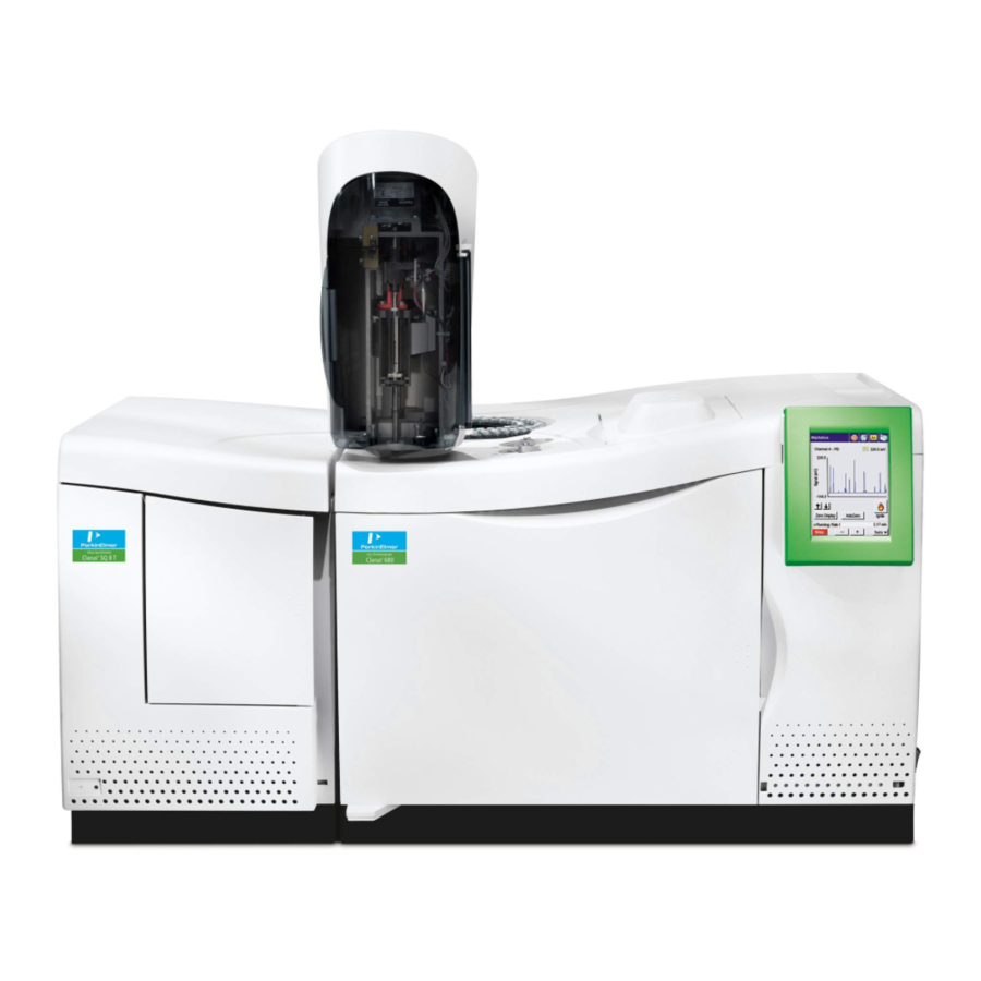
Electron Impact (EI) ionization as well as chemical ionization (CI). The Clarus SQ 8 S and SQ 8 T MS are electron impact (EI) only. Figure 4 Clarus SQ 8 MS with Clarus 680 GC. The Clarus MS system is controlled by a PC using TurboMass Software. The application runs in a Microsoft Windows 7 Professional operating environment. - Page 56 Clarus SQ 8 MS Hardware Guide Figure 5 Clarus SQ 8 Mass Spectrometer. A high-performance, research-grade analytical quadrupole mass analyzer with a quadrupole prefilter assembly transmits only those ions having your selected mass- to-charge ratio. The prefilter rod set improves sensitivity and protects the analytical quadrupole rods from contaminating ion deposits.
-
Page 57: Clarus 580/680 Series Gc
About the Clarus GC/MS System Clarus 580/680 Series GC The Clarus 580/680 Series Gas Chromatograph is a dual-channel, temperature- programmable gas chromatograph (GC). It is available in many configurations, such as with or without, an autosampler, programmable pneumatic control (PPC), and a variety of injector/detector combinations to provide you with total GC flexibility. -
Page 58: Gc Interface (Transfer Line)
Clarus SQ 8 MS Hardware Guide autosampler can run up to 15 injections per vial from as many as 108 vials and one priority vial using one or two autosampler programs (if not under TurboMass control). In the latter case, a different GC method can be used by each program if desired. -
Page 59: Ion Optics Path
About the Clarus GC/MS System Ion Optics Path The Clarus MS ion source consists of a removable ion source. The Ion Source Clarus SQ 8 C also supports a CI source. In the EI source, molecules exit the column where they are bombarded by electrons from the filament and ionized into positive and negative ions as well as neutral species. -
Page 60: Vacuum System
Clarus SQ 8 MS Hardware Guide Vacuum System The source, ion optics, analyzer, and detector are fitted inside a cast aluminum chamber. Vacuum is applied to the chamber using a rotary pump and a turbomolecular pump. The vacuum is monitored through a wide range gauge. The rotary pump sits on the floor and a turbomolecular high vacuum pump is inside the instrument. -
Page 61: Vacuum Pump Options
230 VAC ~ 50/60 Hz MAX POWER 690 VA Vacuum Pump Options The Clarus SQ 8 MS offers two different vacuum pump capacities. Turbomolecular pumps are high-speed turbines which transport the sample and carrier gas molecules away from the mass spectrometer. - Page 62 Clarus SQ 8 MS Hardware Guide Pumping Down a Turbomolecular Pump Vacuum System Select Pump/Vacuum System On from the Options menu on the Tune page. The menu name will change from Pump/Vacuum System On , and the system will begin its pump-down Vent/Vacuum System Off sequence.
-
Page 63: Turbomass Software
About the Clarus GC/MS System TurboMass Software TurboMass software is the user interface of the Clarus system. The following screens show some examples of how you can control Clarus. Interaction is via the mouse and keyboard using menu-driven commands. Printing, file management and other routine procedures are performed using the appropriate Microsoft Windows modules. -
Page 65: Analytical Column
Analytical Column The analytical column inside the Clarus GC oven provides the sample separation. Make sure you select the proper column for your analysis. PerkinElmer offers a wide range of columns in the Gas Chromatography Column Catalog. The TurboMass Tutorial provides additional column selection tips. -
Page 66: Pre-Operational Checklist
Pre-Operational Checklist This checklist provides you with a list of items to check to make sure everything is in working order before you begin to use Clarus. Item Are the gases connected to the GC? Is the proper column connected? Is the proper liner installed in the injector? Are your samples prepared? Is there a GC method? -
Page 67: Maintenance
Maintenance Maintenance... - Page 69 Maintenance...
-
Page 70: Overview
Clarus SQ 8 MS Hardware Guide Overview High electrical voltage is present inside the mass spectrometer. To prevent the risk of electrical shock or injury from high voltage, unplug the AC line cord from the AC outlet and wait at least one minute before opening or removing an instrument panel. - Page 71 Maintenance Do not attempt to make adjustments, replacements or repairs to this instrument except as described in the accompanying user documentation. WARNING N'essayez pas de faire des ajustements, des remplacements ou des réparations à cet instrument, sauf comme décrit dans la documentation de l'utilisateur qui l'accompagne.
- Page 72 Clarus SQ 8 MS Hardware Guide Many of the procedures described in this chapter involve removing potentially toxic contamination deposits using flammable or caustic agents. Anyone performing these operations should be aware of the inherent risks and should WARNING take the necessary precautions.
-
Page 73: Typical Overall Maintenance Schedule
If a fault occurs, you can correct it with minimum difficulty. Advanced maintenance that requires removing complicated mechanical assemblies must be performed by a PerkinElmer Service Representative. For example, an untrained individual should not attempt to remove the manifold but may be able to perform basic maintenance such as draining and filling the forepump. -
Page 74: Monthly
Clarus SQ 8 MS Hardware Guide Monthly • Clean the fan filters on the rear of Clarus MS. • Check the reference gas vial. Refill if necessary. Every Six Months • Replace the forepump oil. • Check the analyzer prequadrupole. Clean if necessary. -
Page 75: Leak Checking
Maintenance Leak Checking Checking for leaks is actually checking the integrity of the vacuum system. You observe masses 4 (helium), 18 (water), 28 (nitrogen), and 32 (oxygen). To leak-check the system, follow this procedure: Ensure that all connections are made to the mass spectrometer. Set the GC split flow to 50 mL/min by pressing the PSSI injector icon on the Clarus GC touch screen. - Page 76 Clarus SQ 8 MS Hardware Guide Display the TunePage dialog by clicking The TunePage dialog is displayed. Make sure the Tune parameters are similar to the values displayed. NOTE: The inlet and source temperatures should be less than 100°C only when venting the system.
- Page 77 Maintenance The indicator box color changes to green and the name of the button changes to Press for Standby. Select Pump from the Options menu. This starts the forepump and the turbomolecular pump. Watch the vacuum gauge readout and allow time for the gauge to achieve 4 x 10⁻⁵ Torr. Observe the displayed masses.
-
Page 78: Tuning The Clarus Ms
Clarus SQ 8 MS Hardware Guide Tuning the Clarus MS After determining that no leaks exist and before acquiring data, you may need to check the mass spectrometer tuning conditions and, if necessary, modify one or more of the tuning parameters. Clarus MS can be tuned either manually or automatically from the Tune window. - Page 79 Maintenance To display the Tune page: 1. While displaying TurboMass sample list screen click The TunePage displays. Turn on the filament and high voltages by clicking Press for Operate at the bottom right of the window. The indicator box turns green to indicate that it is on. Select UltraTune/Custom (AutoTune) from the Options menu, then click Start.
-
Page 80: Preparing Clarus Ms For Hardware Maintenance
Clarus SQ 8 MS Hardware Guide Save this new of the instrument by selecting from the File Tune Save As menu and entering a name for this tune in the File name field. A way to keep track of the tunes is to use dates for the file names. - Page 81 Maintenance Cool the Transfer Line, GC Column Oven, and the Source The transfer line, GC oven, and source are HOT. Touching them can cause serious burns. To prevent personal injury, wait until the oven and transfer line reach the lower setpoint temperature before touching them.
- Page 82 Clarus SQ 8 MS Hardware Guide Remember, the transfer line was heated and it may take at least 10 to 20 minutes to cool. WARNING Rappelez-vous, la ligne de transfert a été chauffée et peut prendre au moins 10 à 20 minutes pour refroidir.
- Page 83 Maintenance NOTE: Mass Spectrometer venting may take several minutes depending on the helium flow and/or vent gas flow into the manifold. The system is now vented to atmosphere (or optional dry gas). Turn off the GC Carrier Gas Set all temperatures to ambient. Once the GC column oven, source, and transfer line are cool you may then turn off the GC carrier gas.
-
Page 84: Removing And Returning The Source
Clarus SQ 8 MS Hardware Guide Removing and Returning the Source To prevent contamination of the mass spectrometer, always wear clean, lint-free, powder-free nitrile, nylon, or PVC gloves before touching, removing or replacing parts. Hold the source by its handle only. Never... - Page 85 AVERTISSEMENT Pull the inner transfer line tube back 25 mm (1 inch). Inner Transfer Tube Pull Back Column 1/4-inch Nut Figure 9 Pulling back the inner transfer tube. Open the Clarus SQ 8 MS access door.
- Page 86 Clarus SQ 8 MS Hardware Guide Hold the source by the edge and rotate it counter clockwise. Access Door Source Figure 10 Rotating the source. Carefully pull out the source. Figure 11 Removing the source.
- Page 87 Maintenance Place the source on a clean surface. Preferably place the handle end on a flat surface so that the source stands in an upright position. Figure 12 The source placed in an upright position.
-
Page 88: Returning The Source
Clarus SQ 8 MS Hardware Guide Returning the Source To prevent contamination of the mass spectrometer, always wear clean, CAUTION lint-free, powder-free nitrile, nylon, or PVC gloves before touching, removing or replacing parts. Hold the source by its handle only. Never touch these parts with ungloved (bare) fingers, as this will introduce contaminants into the system. - Page 89 Maintenance Using a 9/16-inch wrench, tighten the ¼-inch nut on the transfer line. Close the Clarus SQ 8 MS access door.
-
Page 90: Changing A Column
Clarus SQ 8 MS Hardware Guide Changing a Column This procedure outlines the steps required to properly position the end of the column in the Source and connect the column to the MS Transfer Line tube fitting inside the GC oven. - Page 91 Failure to do so may result in less than optimal detector response of target compounds in your analysis. Prior to removing the source from the Clarus SQ 8 MS instrument (for example, to change a filament or clean the source), the column must be pulled back from CAUTION its placement inside the source.
-
Page 92: Physical Measurement Outside The Sq 8Ms
Clarus SQ 8 MS Hardware Guide Physical Measurement Outside the SQ 8MS To prevent contamination of the mass spectrometer, always wear clean, CAUTION lint-free, powder-free nitrile, nylon, or PVC gloves when handling the part of the capillary column that will be inserted into the MS Transfer Line. - Page 93 Maintenance Using the edge of a wafer scribe, score the outside surface of the column perpendicular to its length approximately 2 inches from the end and carefully break it off and discard the cut off piece of column. Jagged or angled cuts should be avoided.
- Page 94 Clarus SQ 8 MS Hardware Guide 10. Slide the column into the Transfer Line tube until the septum is aligned at a distance exactly 10 mm away from the end of the column nut. See Figure 16. Septum Column 1/16-inch Column Nut...
-
Page 95: Alignment Using The 10 Mm Positioning Gauge Tool
Maintenance 12. The column is now installed the MS may be pumped down. Confirm that the proper vacuum level is reached (on the TurboMass software Tune Page). 13. After initially heating the GC oven through one or two analysis cycles, the column nut may loosen. - Page 96 Clarus SQ 8 MS Hardware Guide Confirm that the Source is fully installed in the instrument. If it is not, install the source into the instrument. See Removing and Returning the Source on page 82Error! Bookmark not defined.. Insert the column into the MS Transfer Line tube and carefully slide it toward the source.
-
Page 97: Optical Column Alignment Using The Optional Plug Handle And Sight
Loosen the large nut on the Transfer Line tube assembly using the 9/16 inch wrench and pull back the Transfer Line tube approximately 1 to 2 inches. Remove the source from the Clarus SQ 8 MS instrument. See Removing and Returning the Source on page 82Error! Bookmark not defined.. - Page 98 Clarus SQ 8 MS Hardware Guide Figure 19 Inserting the Plug Handle and Sight.
- Page 99 Maintenance Re-insert the Transfer Line tube assembly and tighten the large nut. Slide a 1/16 inch column nut over the outlet end of the column. With the tapered end facing towards the column nut, slide a graphite/vespel ferrule over the outlet end of the column. See Figure 14. Using a wafer scribe, score the outside surface of the column approximately 2 inches from the end and carefully break it off and discard the cut off piece of column.
- Page 100 Clarus SQ 8 MS Hardware Guide Carefully continue inserting the column into the Transfer Line tube until it becomes visible inside the Plug Handle and Sight. Be careful to avoid inserting the column so far that it hits the far side of the MS vacuum chamber.
- Page 101 See Figure 9. Turn the Plug Handle and Sight counterclockwise to the unlock symbol on the instrument and remove it from the Clarus SQ 8 MS instrument. Insert the source. See Removing and Returning the Source on page Error! Bookmark not defined..
-
Page 102: Refilling The Reference Gas Vial
Clarus SQ 8 MS Hardware Guide Refilling the Reference Gas Vial It is time to refill the reference gas vial when you lose reference gas peaks intensity and you do not see a liquid in the reference gas vial, or any time the mass spectrometer is vented, and the liquid in the vial level appears low. - Page 103 Maintenance Locate the reference gas vial under the top cover of the instrument. Reference Gas Vial Knurled Fitting Figure 22 Reference gas vial and knurled fitting. The toxicity of the FC-43 calibrant is uncertain. Take appropriate precautions to avoid getting the calibrant on your skin or in your eyes.
- Page 104 Clarus SQ 8 MS Hardware Guide Using a pipette or syringe, add 25 to 50 µL but no more than 50 µL of Heptacosa (FC43). See the following figure. Fill the bulb. Never add more than 50 µL. Gas Tight...
-
Page 105: Replacing A Filament
Maintenance Replacing a Filament This procedure is the same for both an EI or CI source. Make sure you are wearing lint-free, powder-free nitrile, nylon, or CAUTION PVC gloves, and that you wipe each part with a methanol dampened Kimwipe. Assurez-vous que vous portez des gants en nitrile, en nylon ou en ATTENTION PVC sans peluche, sans poudre et que vous essuyez chaque partie... - Page 106 Clarus SQ 8 MS Hardware Guide Orient the source so that the filament faces you, then locate the filament retaining clip that holds it in place. Filament Filament Retaining Clip Move the Ceramic Insulating Connector Assembly Down Figure 24 Moving the ceramic insulating connector assembly down.
- Page 107 Maintenance To ensure that the mass spectrometer remains contamination free, CAUTION make sure you are wearing lint-free, powder-free nitrile, nylon, or PVC gloves, and that all tools have been cleaned with a methanol-dampened laboratory wipe. Pour s'assurer que le spectromètre de masse reste sans contamination, ATTENTION assurez-vous d'utiliser des gants de nitrile, de nylon ou de PVC sans peluches, sans poudre et que tous les outils ont été...
- Page 108 Clarus SQ 8 MS Hardware Guide The defective filament assembly will fall out of place, so carefully hold or catch it with your other hand. Filament Figure 25 Removing the defective filament assembly. Position the new filament assembly with the filament side up.
- Page 109 Maintenance female connectors in the ceramic insulating connector assembly. Carefully move the connector assembly upwards to fully encapsulate the four gold leads. You should be able to feel it “click” into position around the leads and close to the underside of the block. Install the source assembly back into the mass spectrometer by following the procedure Removing and Returning the Source on page 82Error! Bookmark not defined..
-
Page 110: Source Maintenance
Clarus SQ 8 MS Hardware Guide Source Maintenance NOTE: Before beginning this procedure, you may want to have on hand the following source component kits; Rebuild Kit Part No. N6480080 and N6480081. To ensure that the mass spectrometer remains contamination free, wear... - Page 111 Maintenance Using your thumb and forefinger, push down the ceramic insulating connector assembly to release it from the filament leads, trap lead, and repeller lead. Press down on the retaining clip to release it from the locked position. The filament assembly will fall out of place, so carefully hold or catch it with your other hand.
- Page 112 Clarus SQ 8 MS Hardware Guide Figure 28 Removing the source parts for cleaning. Cleaning NOTE: You can do the following cleaning method of aluminum oxide paste to polish the flat surfaces of the parts. For either cleaning method, the final step you must sonicate the parts in an ultrasonic bath of methanol for at least five minutes.
- Page 113 Maintenance Do not allow the methanol and acetone to touch the O-ring on the CAUTION source. Ne laissez pas le méthanol et l'acétone toucher le joint torique sur la ATTENTION source. 4. Carefully drain the acetone. 5. Dry off the source parts using lint-free tissue and/or clean compressed nitrogen gas to prevent solvents from drying on these parts and leaving a residue.
- Page 114 Clarus SQ 8 MS Hardware Guide Position the filament assembly with the coiled filament wire facing and centered in the orifice in the ion volume and the white ceramic rests on the tab. Insert the Filament retaining clip into the slot in the block to hold it in place.
-
Page 115: Mass Analyzer Maintenance (Perkinelmer Service Representative Only)
Maintenance Mass Analyzer Maintenance (PerkinElmer Service Representative Only) This procedure is intended PerkinElmer Service Representative. WARNING Cette procédure est destinée au représentant du service PerkinElmer. AVERTISSEMENT The analyzer element of any high performance quadrupole mass spectrometer is, of necessity, a finely machined assembly that has been precisely aligned using specialized equipment. -
Page 116: Cleaning Materials
Clarus SQ 8 MS Hardware Guide Cleaning Materials • Wooden stick cotton swabs • Deionized Water • 6000 Grade Micro Mesh (Part No. N9303420) • 8000 Grade Micro Mesh (Part No. N9303421) • 600 grit aluminum oxide in DI Water with a few drops of methanol to make a paste •... -
Page 117: Removing And Returning The Ion Optics Assembly
Tools Required: • Medium sized Philips screwdriver • 5 mm Allen Key Power down and vent the Clarus SQ 8 MS. - Page 118 Clarus SQ 8 MS Hardware Guide Remove the source. See Removing and Returning the Source on page 82Error! Bookmark not defined.. Use the medium sized Philips screwdriver to remove the two screws on the left access panel. See the following figure.
- Page 119 Maintenance Lift off the top cover by manipulating the slots on the right-hand side of the cover off the metal tabs on the instrument. See the following figure. Top Cover Top Cover Slot (2) Metal Tab on Chassis (2) Figure 31 Removing the top cover. Place the top cover in a safe location.
- Page 120 Clarus SQ 8 MS Hardware Guide Tilt the front cover towards you slightly to provide clearance for removing the lid. It is not necessary to remove the front cover completely from the instrument. Use a 5 mm Allen key to loosen the four hex screws that hold the optics assembly in place.
- Page 121 Maintenance From the rear of the optics assembly disconnect the four cables. RF Generator Connector Sliding Lock attachment Cables Figure 33 Disconnecting the cables at the rear of the optics assembly Locate the Sliding Lock attachment on the RF Generator Cable connector, then press down on the Sliding Lock attachment to release the lock on the connector.
- Page 122 Clarus SQ 8 MS Hardware Guide Press Down to Release the Lock Figure 34 Sliding Lock attachment on the connector. Remove the RF Generator Cable connector. See the following figure. Figure 35 Removing the RF Generator cable. NOTE: The metal tube attached to the reference gas vacuum hose has a ferrule on it that may slip off when the nut is removed from the reference gas valve fitting.
- Page 123 Maintenance From the front of the optics assembly disconnect the fan cable connector, reference gas valve cable connector, the source connector and the nut for the reference gas vacuum hose. See the following figure. Source Connector Nut and Ferrule for Reference Gas Vacuum Hose Fan Cable...
- Page 124 Clarus SQ 8 MS Hardware Guide Returning the Ion Optics Assembly To prevent contamination of the mass spectrometer, always wear clean, lint-free, powder-free nitrile, nylon, or PVC gloves before touching, removing or replacing parts. Never touch these parts with ungloved CAUTION (bare) fingers, as this will introduce contaminants into the system.
- Page 125 Maintenance Make sure that the Sliding Lock attachment on the RF Generator Cable connector is in the “down” (unlocked) position prior to connecting it to the receptacle on the RF Generator box as shown in the following figure. Figure 37 RF Generator cable connector. Connect the RF Generator Cable connector to the receptacle on the RF Generator box.
- Page 126 Clarus SQ 8 MS Hardware Guide Using any Allen key, as shown in the following figure, pull up on the underside of the Sliding Lock attachment to lock the connector into place. See the following figure. Allen Key Figure 39 Sliding Lock attachment shown in the “up” (or locked) position.
-
Page 127: Replacing The Electron Multiplier
Maintenance Replacing the Electron Multiplier The electron multiplier lifetime is dependent on the number of ions detected. You can increase its life by correctly using the solvent delay settings and minimizing air leaks. To replace an electron multiplier: Remove the ion optics assembly. See Removing and Returning the Ion Optics Assembly on page 114Error! Bookmark not defined.. -
Page 128: Cleaning The Prequads
Clarus SQ 8 MS Hardware Guide Replace with a new electron multiplier by sliding it forward toward the source and clipping it back into place. Return the ion optics assembly. See Removing and Returning the Ion Optics Assembly on page 114. - Page 129 Maintenance Using a very fine abrasive paper (8000 grade) clean the ion burns off the prefilters. Wipe the prequads with a methanol dampened laboratory wipe. Blow dry with helium or dry nitrogen. Return the ion optics assembly to the vacuum manifold. See Removing and Returning the Ion Optics Assembly on page 114.
- Page 130 Complete pump instructions are in the instruction manual supplied with the pump. Maintanenace of the Turbomolecular Pump You should never service the turbomolecular pump. Call your PerkinElmer Service Representative for the maintenance and any problems you may have with the pump.
- Page 131 Maintenance Determine if the oil level is between the Max Oil Level and Min Oil Level marks next to the window. • If the oil level is closer to the Min Oil Level mark, add oil. Use Edwards 45 oil (Part No. 09923492, 1 liter). •...
- Page 132 Clarus SQ 8 MS Hardware Guide Run the pump until the oil appears clear. Changing the Oil Warm the oil by running the pump for at least 10 minutes, and then switch off the vacuum system. Unplug the pump from the AC outlet and disconnect it from your vacuum system.
- Page 133 Maintenance Place the pump on a table. Place a drain container under the drain plug. Raise the end of the pump opposite the drain plug by putting a block under it. If you were running toxic samples, the oil is contaminated as toxic waste.
- Page 134 Clarus SQ 8 MS Hardware Guide Inline Gas Purifiers The inline gas purifier lets you change the trap without introducing contaminants into your system. This eliminates the need to flush the system. The trap contains oxygen, moisture and hydrogen adsorbents and is packed and purged under helium.
- Page 135 Maintenance Changing from EI to CI Mode Changing modes consists of the following: • Connecting the CI gas. • Changing the source and instrument control mode. • Leak-checking. • Setting-up CI. Connecting the CI Gas Hazardous gas vapors. When using ammonia gas when running in the chemical ionization (CI) mode, it is necessary to vent the mass spectrometer effluent from the forepump exhaust into a fume hood or charcoal trap.
- Page 136 Clarus SQ 8 MS Hardware Guide Explosive Hazard. If the hydrogen, methane or iso-butane is turned on without a column attached to the injector and/or detector fittings inside the oven, the gas could diffuse into the oven creating the possibility of an explosion.
- Page 137 Maintenance It must be solvent-washed and nitrogen-dried. The bulkhead connector at the rear of the instrument is a 1/8 inch Swagelok fitting. If ammonia is used for chemical ionization, all fittings and tubing must be stainless steel to avoid corrosion. Also, the forepump must be vented to a fume hood or trap.
-
Page 138: Changing To Ci
Clarus SQ 8 MS Hardware Guide Leak-check all connections. ROTARY PUMP Rotary Pump Warning Power POWER IN Power In WATER WATER 4 10 CI GAS VENT Warning 15 psi 5 psi 50 psi (103 kPa) (35 kPa) (345 kPa) Labels... -
Page 139: Leak Checking
Maintenance Select Pump from the Options menu. This starts the forepump and the turbomolecular pump. In the Vacuum Pressure Gauges area of the window, observe the Pirani gauge time line and the Penning gauge time line. Wait about 5 minutes until the vacuum gauge achieves about 2.5 x 10⁻⁵. - Page 140 Clarus SQ 8 MS Hardware Guide The CI source running in the CI mode without reagent gas to produce an EI emission similar to the EI mode but with reduced sensitivity. You will leak-check your system this way. If mass 28 is larger than mass 18, you have a leak. Determine the source of the leak...
-
Page 141: Setting-Up Ci
Maintenance Setting-Up CI After verifying that no leaks exist, you can proceed to set up the CI mode for an analysis. Setting the Parameter Values Display the following CI window: Set the values as shown in the following table. - Page 142 Clarus SQ 8 MS Hardware Guide Adjust the Reagent Gas for CI+ When running in the CI+ mode with reagent gas off, the resulting EI spectra have about 10x lower sensitivity than with the EI source. If using methane reagent gas, the reagent ions at m/z 17 (CH...
- Page 143 Maintenance CI Reagent Gas Adjustment Knob Figure 45 CI reagent gas adjustment knob. Carefully turn the delicate CI reagent gas adjustment knob fully clockwise until you feel it stop. Select CI Gas On from the Gas menu. A check mark appears next to the option. NOTE: Always turn on the CI gas before Operate to avoid a pressure surge hitting the filament.
- Page 144 Clarus SQ 8 MS Hardware Guide When using methane gas, carefully turn the CI adjustment knob counterclockwise until m/z 16 is low or non-existent, and m/z 29 is maximized. As you turn the knob, reduce the multiplier voltage to keep the peaks on scale.
- Page 145 Maintenance Tuning may be optimized on the m/z 69, 219, 414, and 652 ions of the heptacosa reference gas. Click Press for Standby to turn off Operate, followed by the CI gas. You are now ready to run your CI+ analysis. Adjust the Reagent Gas for CI- Open the CI gas inlet by selecting CI Gas from the Gas menu.
- Page 146 Clarus SQ 8 MS Hardware Guide keep the source cleaner, but may increase fragmentation. For example, down a little from EI to minimize fragmentation. 120 °C is the practical lower limit. Ion Energy Approx. 1 or 2 Optimize the amount of reagent gas flowing into the source by using two heptacosa ions, m/z 452 and 633, which usually produce relative intensities of 65 –...
- Page 147 Maintenance Make sure the “Use Air Refs” check box is not selected. CAUTION Assurez-vous que la case à cocher "Utiliser Air Refs" n'est pas sélectionnée. ATTENTION Click the Start button to display the following dialog box. Click Acquisition Parameters and enter the following values. Click OK to begin calibration.
-
Page 148: Troubleshooting
Troubleshooting... - Page 149 Troubleshooting...
-
Page 150: Overview
Troubleshooting Overview The following sources of problems can occur in gas chromatography and mass spectrometry: • The operator: When the operator is new to chromatography/mass spectrometry and/or a new instrument, problems can be introduced during the learning curve. Once the operator becomes familiar with both the technique and the instrument, this problem source diminishes greatly. -
Page 151: Spare Components
Troubleshooting Spare Components The following list contains items you should have on hand to help solve problems. • New syringes: a syringe can break, become plugged or begin leaking. Always have spare syringes available. • Duplicate columns: a column does not last forever; always have a duplicate column on hand in the event that your separation begins to degrade. - Page 152 Clarus SQ 8 MS Hardware Guide Change the simplest thing first. For example, if you suspect a gas leak, the easiest change to make is the GC septum instead of replumbing the internal pneumatics. Change only one parameter at a time and check for its effect. If you change three items at once and your problem goes away, you may not know which of the three moves or combination of moves corrected the problem.
-
Page 153: Troubleshooting Chart
AC outlet. instrument). No AC power to the outlet. Check the outlet. Fuse blown. Call a PerkinElmer service engineer. Mass Spectrometer is on Forepump is not plugged into Plug the forepump line but the forepump is not... - Page 154 Clarus SQ 8 MS Hardware Guide Problem Probable Cause Solution The ultimate pressure is Is the cooling inadequate? Check the cooling-air flow and poor. correct if possible. Check the cooling-air duct for obstructions and correct as necessary. If the cooling air flow is fine...
- Page 155 Troubleshooting Problem Probable Cause Solution Turbo pump will not Pump malfunction. Call a PerkinElmer service accelerate engineer. Pump controller Call a PerkinElmer service malfunction. engineer. GC is not properly Set the proper GC configured. configuration for your site. Vacuum light continues to Large leak.
- Page 156 Clarus SQ 8 MS Hardware Guide Problem Probable Cause Solution No spectra, or very little Bad tune. Run AutoTune. spectra at the low mass end. No spectra, not even noise at Loose electrometer cable. Reset the cable. a high multiplier voltage.
- Page 157 Troubleshooting Problem Probable Cause Solution Poor or inadequate Leaking injector septum. Replace the septum. sensitivity. Leak from injector Tighten/replace ferrules. ferrules. Foreign material in the Clean the injector. injector. Peak splitting. Prevent double injections. Dry the outside of the injector needle.
- Page 158 Clarus SQ 8 MS Hardware Guide Problem Probable Cause Solution Solvent tailing. Inadequate splitter flow. Increase the splitter flow. Column not properly Reinstall the column in the installed in the injector. injector. Loss of high end compounds. Temperature setting too...
- Page 159 Troubleshooting Problem Probable Cause Solution Poor sensitivity (correct Column is improperly Reinstall the column and amount of sample is reaching positioned in the ion check the cut at the end the mass spectrometer). source. that fits in the source. Improper tuning, or a Check the tuning.
- Page 160 Clarus SQ 8 MS Hardware Guide Problem Probable Cause Solution Unusually high emission Ion volume dirty. Clean the inner source. setting. Prefilters dirty. Clean the prefilters. Poor tuning. Retune. Tuning peaks show Poor tuning. Retune. precursors (forward slope shoulders). Dirty prefilter.
- Page 161 Large air leak. See procedure for leak- status OK. checking. Detector voltage too low. Increase multiplier value. Electronics failure. Call a PerkinElmer service engineer. Poor sensitivity. Beam Column improperly Check and reinstall the instability/peaks breaking up. installed. column if necessary.
- Page 162 Clarus SQ 8 MS Hardware Guide Problem Probable Cause Solution Piece of column broken off in Remove the inner source, the ion chamber. check for and remove piece of column. Source filament is bent. Check and replace filament if necessary.
- Page 163 Troubleshooting Problem Probable Cause Solution Excessive noise. Dirty source. Clean the source. GC and MS on separate power Connect GC and MS together supplies. with the ground strap. Multiplier voltage too high. Run AutoTune. Data acquisition thresholds set too Raise the thresholds. low.
-
Page 164: Chromatography Related
Clarus SQ 8 MS Hardware Guide Chromatography Related Problem Probable Cause Solution Inconsistent retention Injector septum leak. Replace the septum. time. Carrier gas manifold leak. Locate and fix the leak. Rising Total Ion Column bleed. Disconnect the column from Chromatogram baseline. - Page 165 Troubleshooting Problem Probable Cause Solution Dirty injector liner. Clean or replace. Column has active sites. Equilibrate or replace. Chromatographic peaks Injector too cool. Raise injector temperature. too wide. Sample overloading the Use a split injection or a smaller column. sample. Incorrect GC oven program.
- Page 166 Clarus SQ 8 MS Hardware Guide Problem Probable Cause Solution Slowly falling baseline Split valve left closed during Open the split valve. (from a high initial value). acquisition. Inadequate purge flow rate. Increase flow rate. Poor off for too long.
- Page 167 Poor calibration. Recalibrate. Air leak. Locate and fix. Active sites in column/liner. Replace column/liner. Intermittent source heater Call a PerkinElmer service failure. engineer. Poor S/N on test standards. See low sensitivity causes above. Incorrect GC/MS method Use the correct method.
-
Page 168: Spectral Related
Clarus SQ 8 MS Hardware Guide Spectral Related Problem Probable Cause Solution Noisy spectra. Dirty source. Remove and clean the source. Peak detection threshold set too low. Raise the thresholds. Multiplier voltage set too high. Lower the multiplier voltage. Spectrum distortion. - Page 169 Troubleshooting Problem Probable Cause Solution Contamination. Locate the contamination and eliminate it. Co-eluting components. Change your sample preparation or chromatography. Incorrect column alignment. Reinstall the column. Section of a mass range Corruption of data file. Reacquire data. missing from a spectrum.
-
Page 170: Communications Related
Clarus SQ 8 MS Hardware Guide Communications Related Problem Probable Cause Solution Will not boot MS. PC (computer) to MS cable Check and reset the cable. has a loose connection. Transient in power supply Reboot the PC (computer). has halted communications. -
Page 171: Forepump Related
Probable Cause Solution Pump does not start. Forepump switched off. Switch on the pump. Blown fuse. Call a PerkinElmer service engineer. Electrical supply voltage Determine the correct voltages, does not match that of the and correct. Check the voltage pump motor. - Page 172 Clarus SQ 8 MS Hardware Guide Problem Probable Cause Solution Contaminated oil. Drain and refill with new oil. Vacuum fitting dirty or Check and replace if damaged. necessary. Noisy Pump. Motor fan cover damaged. Call a PerkinElmer service engineer. Worn motor bearings.
- Page 173 Troubleshooting Problem Probable Cause Solution External oil leak. Outer shaft seal worn or Call a PerkinElmer service damaged. engineer. Oil box gaskets deteriorated. Call a PerkinElmer service engineer. Oil leak from gas ballast Call a PerkinElmer service control. engineer. Oil leak from drain plug.
-
Page 174: Message Dialogs
Clarus SQ 8 MS Hardware Guide Message Dialogs When operating the instrument message dialog boxes will sometimes appear. The following table is the Icon Key followed by tables that show the Message Title, icon, dialog message and recommended action. Icon Key... - Page 175 Press OK to close the Gauge gauge. message. Failure Restart the system, if you still have this failure message contact your PerkinElmer service representatives. Pump Press OK to close the The vacuum system is off and the failure- message. system can now be vented. The carrier Safe to Vent gas should be turned off.
- Page 176 Clarus SQ 8 MS Hardware Guide Message Title Icon Message Action Vacuum Leak- Press OK to close the The vacuum system is off and the Safe to Vent message. system can now be vented. The carrier gas should be turned off Check the system for any leaks and correct.
- Page 177 Troubleshooting Message Title Icon Message Action Backing Pump is The system is not in an operating If the transfer line or the state. A vacuum leak or a vacuum source temperatures are gauge failure could have occurred. above 100C, please wait until they have cooled If the transfer line or the source before pressing OK.
- Page 178 TurboMass Software Installation...
-
Page 179: Index
Index... - Page 181 Index Index Aluminum oxide, 109 Gases, 40 Caution, 80 Hardware Checklist maintenance, 78 pre-installation, 43 pre-operational, 64 Chemicals Definitions of Warnings, 32 Inline Gas Purifiers, 131 Hazardous, 30 Introduction to TurboMass, 53 Ion source, 57 leak checking, 136 setting parameter values, 138 setting up, 138 Column, 63 Labels...
- Page 182 Clarus 600 MS Hardware Guide Overview Transfer line Clarus 600/560D GC, 55 cooling, 79 ion source, 57 Traps maintenance, 69 click on connectors, 131 reference gas inlet, 56 replacement, 131 troubleshooting, 147 Troubleshooting, 147 chart, 150 overview, 147 spare components, 148 Tune page, 61 Pollution degree, 34 Tuning, 76...
- Page 183 ...
- Page 184 PerkinElmer 710 Bridgeport Avenue Shelton, CT 06484-4794, U.S.A. Internet: http://www.perkinelmer.com email: info@perkinelmer.com PerkinElmer is a registered trademark of PerkinElmer, Inc.
Need help?
Do you have a question about the CLARUS SQ 8 MS and is the answer not in the manual?
Questions and answers