Table of Contents
Advertisement
Quick Links
Advertisement
Table of Contents

Related Manuals for PerkinElmer CLARUS 590 GC


Summary of Contents for PerkinElmer CLARUS 590 GC
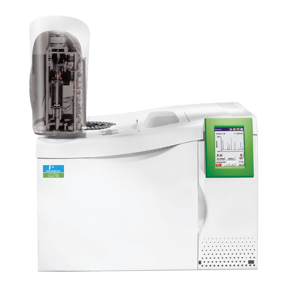
- Page 1 GAS CHROMATOGRAPHY 590 GC LARUS User’s Guide...
- Page 2 The information contained in this document is subject to change without notice. Except as specifically set forth in its terms and conditions of sale, PerkinElmer makes no warranty of any kind with regard to this document, including, but not limited to, the implied warranties of merchantability and fitness for a particular purpose.
-
Page 3: Table Of Contents
Table of Contents Introduction ........................ 11 About This Manual ......................13 Conventions Used in this Manual .................13 About Notes, Cautions, and Warnings ..............13 Screen Abbreviations .......................16 Glossary of Clarus GC Terms ....................17 Autosampler Terms.....................17 Instrument-Specific Terms ..................17 Glossary of Chromatographic Terms ................19 Touch Screen Navigation ..................... - Page 4 4 . Clarus 590 GC User’s Guide Manual Pneumatics ....................48 ECD ...........................49 PPC ........................50 Active Method .......................50 Configuration Screen ....................50 Manual Pneumatics ....................50 PID ..........................51 PPC ........................51 Manual Pneumatics ....................51 NPD ...........................52 PPC ........................52 Manual Pneumatics ....................52 FPD ...........................53 PPC ........................53 Manual Pneumatics ....................53...
- Page 5 About This Manual . 5 Setting the Septum Purge Mode and Offset ...............81 Setting Up Valves ......................87 Setting the Split Mode Using PPC .................87 Setting the Split Mode Using Manual Pneumatics ............89 Set the Solenoid Valve for Split Operation ..............89 Measure and Adjust the Split Vent Flow ...............90 Set up the Splitless Mode for a CAP or PSS Injector ............93 Setting the Splitless Mode Using PPC Modules ..............93...
- Page 6 6 . Clarus 590 GC User’s Guide Cell Failure or Damage ...................129 Reporting Radiation Incidents, Theft or Loss ............130 Other Requirements ....................130 United Kingdom Regulations ..................130 ECD Setup Summary ....................130 Vent the ECD Outlet ....................131 Adjust the Make-up Gas Flow .................132 Set the Make-Up Gas in the PPC Version ..............132...
- Page 7 About This Manual . 7 Set the FPD Temperature ..................174 Attach a Flowmeter to the FPD ................175 Adjust the Hydrogen Flow ..................175 Adjust the Air Flow ....................178 Turn On the Photomultiplier Tube ................179 Ignite the Flame ....................180 Detector Temperatures ....................183 Range ..........................184 Setting the PID or NPD Range ..................184 Changing the PID or NPD Range During a Run .............184...
- Page 8 8 . Clarus 590 GC User’s Guide Run/AutoSampler .......................226 Setup .........................227 Language drop down menu ..................228 Brightness field......................228 Date/Time Set .......................228 Startup ........................229 Sleep ........................229 Pneumatics ........................230 PPC Configure .......................230 Connecting the PPC Modules ....................231 PPC Connect ........................233 Define Detector Dialog ....................237 Define Aux .........................238...
- Page 9 About This Manual . 9 Flame Ionization Detector (FID) ...................270 TCD ...........................273 Autosampler........................277 Index ........................... 279...
- Page 10 10 . Clarus 590 GC User’s Guide...
-
Page 11: Introduction
I ntroduction... - Page 12 12 . Clarus 590 GC User’s Guide...
-
Page 13: About This Manual
UPPERCASE text, for example ENTER or ALT, refers to keys on the PC keyboard. '+' is used to show that you have to press two keys at the same time, for example, ALT+F. All eight digit numbers are PerkinElmer part numbers unless stated otherwise. About Notes, Cautions, and W arnings Three terms, in the following standard formats, are also used to highlight special circumstances and warnings. - Page 14 14 . Clarus 590 GC User’s Guide W e use the term CAUTI ON to inform you about situations that could result in serious damage to the instrument or other CAUTION equipm ent. Details about these circum stances are in a box like this one.
- Page 15 About This Manual . 15 W e use the term W ARNI NG to inform you about situations that could result in personal injury to yourself or other persons. Details about these circum stances are in a box like this one. WARNING Warning (Warnung) Bedeutet, daß...
-
Page 16: Screen Abbreviations
16 . Clarus 590 GC User’s Guide Screen Abbreviations AUX – Auxiliary zone Cap – capillary split/splitless injector Cmptr – computer Ctrl – syringe control parameters ECD – Electron Capture Detector FID – Flame Ionization Detector FIDW – Wide Range Flame Ionization Detector FPD –... -
Page 17: Glossary Of Clarus Gc Terms
Glossary of Clarus GC Terms . 17 Glossary of Clarus GC Term s The glossary of Clarus GC terms are divided into two types: • Autosampler Terms Instrument-Specific Terms • Autosam pler Term s Term Description Washes Washing the syringe. The number of prewashes of sample to prime the syringe (no pumping). - Page 18 18 . Clarus 590 GC User’s Guide Term Description Equilibration The delay time after the method set points have been reached before the system becomes READY. Flameout PPC version only. Detects if the flame is on to prevent injection into a nonfunctioning system and subsequent loss of sample.
-
Page 19: Glossary Of Chromatographic Terms
Glossary of Clarus GC Terms . 19 Glossary of Chrom atographic Term s Adsorption – A process that occurs at the surface of a liquid or solid as a result of the attractive forces between the adsorbent and the solute. These forces may be physical or weakly chemical. Analysis –... - Page 20 20 . Clarus 590 GC User’s Guide M obile phase – The gas which carries the solute (sample) along and over the column material. This carrier gas is inert and usually helium, nitrogen, or hydrogen. Noise – Background signal fluctuations arising from a detector response. This response is the result of the column installed, carrier gas purity, electronic components, etc.
-
Page 21: Touch Screen Navigation
Touch Screen N avigation... - Page 22 22 . Clarus 590 GC User’s Guide...
-
Page 23: Chapter Overview
Chapter Overview . 23 Chapter Overview You operate the Clarus GC using the touch screen. The touch screen is the interface between you and the instrument, enabling you to control the Clarus GC in order for you to perform your analyses easily and conveniently. -
Page 24: Touch Screen
24 . Clarus 590 GC User’s Guide Touch Screen The main display area on the touch screen are referred to as screens. You use various screens to set up your Clarus GC to perform the analyses. These screens contain: Entry fields which allow you to make entries, •... -
Page 25: Tabs
Touch Screen . 25 Tabs Some of the active method screens include tab to allow you to switch views associated with a specific channel. Non-Configured Devices If a device is installed but not configured, or configured as None, the graphic and light are grayed out. Touching the button prompts the following dialog box. -
Page 26: Non-Installed Devices
26 . Clarus 590 GC User’s Guide Non-installed Devices If a device is not installed, a grayed out deactivated button with no indicator light appears in the designated position. Touching the button prompts the following dialog box: R un Button The Run icon displays the Manual injection and Autosampler settings if the device is enabled. -
Page 27: Manual Injection
Touch Screen . 27 When the Autosampler is disabled, the Run button displays the Manual inject screen. When the instrument is ready, touch the Start button to begin the analysis. The countdown enable check box is selected by default. You can stop the countdown if needed. M anual Injection If no Autosampler is installed or configured, the Run button displays the Manual injection screen. -
Page 28: Signal Button
28 . Clarus 590 GC User’s Guide Signal Button The Signal icon displays the graphic signal for the active method. If the system is not running, a baseline appears on the graph. Raw signal signal Processed The Signal screen displays the selected detector signal over a fixed time period (2 minutes) with you selecting the scaling factor. -
Page 29: Signal Display And Scaling
Touch Screen . 29 scrolls back so the start is now +1 minute, the last 0.75 minutes are displayed from there, and the signal then scrolls out again. The signal is plotted continually before, during and after a run. Signal Display and Scaling The signal display at the top of the screen displays the signal level of the detector in mV. -
Page 30: Injector And Detector Buttons
30 . Clarus 590 GC User’s Guide Injector and Detector Buttons The screen is organized with Channel B devices above Channel A to reflect the position of the channels on top of the GC. Injector and detector buttons display the active method settings for each device. -
Page 31: Oven Button
Touch Screen . 31 Oven Button The oven button provides access to the oven program settings and graph. If both channels are running and the Oven is accessed from the Status screen, it defaults to Channel A. The oven program screen displays the same tabs and navigation icons as the injector and detector active method screens. -
Page 32: Navigation Bar
32 . Clarus 590 GC User’s Guide Navigation Bar The navigation bar provides icons to allow users to seamlessly toggle between channels as well as access the same main areas of the system available from the status screen. The following diagram shows the navigation bar with the corresponding icons on the status screen. -
Page 33: Injectors
Injectors . 33 I njectors The injector elements that appear on a particular injector screen depend on the injector type as well as selected configuration options. Some injector types offer a variety of options while others are more limited. The labels in the following screen capture identify the main components of an Active Method injector screen. -
Page 34: Pssi
34 . Clarus 590 GC User’s Guide P SSI This section describes the main components of the PSS active method screen and the relationship between program and configuration options. Configuration Options The following screens shows the Configuration options and how they correspond to the entry fields in the Active Method. - Page 35 Injectors . 35 To modify the temperature program during a run, touch the program button. You can modify the temperature, time, or rate. However, if the program is currently in that step, the changes will be ignored.
-
Page 36: Isothermal Program
36 . Clarus 590 GC User’s Guide Isotherm al Program If the program is isothermal, the temperature of the injector is held constant for the duration of the run. Changes entered in the field take effect immediately. Carrier Gas Program The Carrier Gas options for PSSI include Pressure, Flow, or Velocity. - Page 37 Injectors . 37 Flow The carrier gas is configured for Flow. This option appears in the entry field. Touching the Program button in the Active Method displays the Carrier Flow Program. Velocity The carrier gas is configured for Velocity. This option appears in the entry field. Touching the Program button in the Active Method displays the Carrier Velocity Program.
-
Page 38: Split Flow
38 . Clarus 590 GC User’s Guide Split Flow The PPC system adds the split flow offset to the method's split flow rate setpoint to obtain the Total split flow rate delivered to the inlet system. The total value is equal to the setpoint flow rate (the flow at the column entrance) plus the offset flow rate. -
Page 39: Packed (Pkd)
Injectors . 39 P acked (P kd) The packed injector has a fixed, non-programmable temperature field. The carrier gas can be programmed by Pressure or Flow as shown in the following screens. The following procedure shows how to navigate through the screens to configure PPC for a packed column injector. - Page 40 40 . Clarus 590 GC User’s Guide 3. Touch the PPC Connect button. 4. Touch the OK button. 5. Touch Carrier B to Configure your injector for PPC. The following Caution appears. 6. Select Pres Read from the drop- down 7.
- Page 41 Injectors . 41 10. The Configure Injector B screen appears 11. Select Pressure or Flow from the drop- down menu 12. To exit out of Configuration, touch the OK button then touch the Close button. 13. Display the active method and view the B- Pkd injector parameters as shown on the right...
-
Page 42: Poc
42 . Clarus 590 GC User’s Guide P OC The POC injector can be programmed by Inlet or Oventrack. The packed on column injector can be programmed by Inlet (POCI) or Oven (POCO). The POC injector is configured and controlled according to the same parameters as the PSS injector. -
Page 43: Oven
Oven . 43 Oven The Oven Temperature Program provides fields and a graph that reflect the current temperature program as shown in the screen on the left below. Pressing the Go to button invokes a dialog box that allows users to raise the temperature to a value associated with another step. The last step of the current program is selected by default. -
Page 44: Aux Zone
44 . Clarus 590 GC User’s Guide Aux Zone If the GC is configured with an auxiliary zone, the button appears on the status screen. Touching the Aux button displays a dialog box with the setpoint and actual temperature. -
Page 45: Detectors
Detectors . 45 Detectors Detector screens provide fields that allows you to control a number of parameters during a run, such as temperature, range, and attenuation. Other active elements include a Heater Off check box to turn off the detector and an AutoZero check box. Selecting the AutoZero check box prompts the system to zero the signal before the run and also activates the Signal button on the Signal screen. -
Page 46: Auto-Ignite Process
46 . Clarus 590 GC User’s Guide After the flame ignites, the output level is monitored to confirm ignition before producing a READY signal. If ignition is not confirmed, the ignition process repeats up to two more times if needed. If ignition is not achieved after three attempts, the flame gases are set to off and a dialog box appears displays the following message: “Flame 1 or 2 failed to ignite.”... -
Page 47: Configuration Settings
Detectors . 47 Configuration Settings The following graphic shows the Configuration Screen with the settings that appear on the Active Method Screen. Active Method Configuration Screen M anual Pneum atics The manual pneumatics version of the FID shares several common elements with the PPC version. The only difference is that the gas flow settings do not appear on the screen. -
Page 48: Ppc
48 . Clarus 590 GC User’s Guide Active Method Configuration Screen M anual Pneum atics... -
Page 49: Ecd
470º C. If this occurs, the following message appears: Warning Instrument Shutdown Thermal Runaway xxxxxx zone Call your PerkinElmer service representative Instrument shutdown also occurs if there is a PRT (Platinum Resistance Thermometer) or MPU (Micro Processor Unit) failure. In this case, the following message appears: Instrument Shutdown... -
Page 50: Ppc
50 . Clarus 590 GC User’s Guide Active M ethod Configuration Screen M anual Pneum atics... -
Page 51: Pid
Detectors . 51 P I D The Photoionization Detector (PID) is designed to allow the effluent from a chromatographic column to be ionized by ultraviolet light (provided the ionization potential of the effluent is less than that of the UV source). -
Page 52: Npd
52 . Clarus 590 GC User’s Guide NP D The nitrogen phosphorus detector (NPD) is a highly specific thermionic detector for organically bound nitrogen and phosphorus. The detector operates by electrically heating a glass bead, that contains an alkali metal, to the point where it emits electrons. -
Page 53: Fpd
Detectors . 53 FP D In the Flame Photometric Detector (FPD), the column effluent is mixed with hydrogen and then burned in air. Light emitted from the flame passes through a lens, a filter, and to a photomultiplier tube, which generates an electrical signal. -
Page 54: Timed Events
54 . Clarus 590 GC User’s Guide Tim ed Events Events Tab The Events tab accesses the timed events table, buttons, valves (relays), and Aux gas controls. Screen Element Enabling Timed events table Always Aux gas button PPC configuration Relays button... -
Page 55: Add
Timed Events . 55 Touching this button displays a settings page that allows you to specify an event to add to the table. Error Messages Edit Touching this button displays the active method page for editing timed events. If the GC is running, then edited events at times before the run time at which the edited list is accepted do not occur until the next run. -
Page 56: Clear
56 . Clarus 590 GC User’s Guide Clear Touching this button deletes the contents of the entire event table. A dialog box confirms the action. Pressing Yes clears the table. Touching the No button closes the dialog box and retains the contents of the Events table. -
Page 57: Aux Zones
Timed Events . 57 • No timed event should have the same time as another timed event. • Time resolution is 0.01 minutes. • Timed Events may be entered and removed in any sequence. Pressing the Clear button prompts a dialog box: •... -
Page 58: Pneumatic Auxiliary Zones
58 . Clarus 590 GC User’s Guide To modify the temperature, press the minus or plus button. Touch OK to implement the value and close the dialog box. Pneum atic Aux iliary Zones Up to four pneumatic zones can be set for PPC carrier gas control. When one or more of the aux zones is configured, the following button appears on the status screen. -
Page 59: Using The Active Method
Using the Active M ethod... - Page 60 60 . Clarus 590 GC User’s Guide...
-
Page 61: Overview
Overview . 61 Overview The Clarus GC is controlled by a collection of operating parameters called the Active Method. You can prepare and save up to five methods and make any one of them the Active Method. However, the fifth method is reserved for TotalChrom (external computer controlled software) and may be overwritten. -
Page 62: Editing The Active Method
62 . Clarus 590 GC User’s Guide Editing the Active M ethod If you have read and used the chapters in this manual sequentially, as recommended, by now you have probably installed and conditioned one or two columns, and set up one or two detectors. Also, you were probably not aware at the time that you modified certain Active Method parameters. -
Page 63: Getting Ready To Edit The Active Method
Getting Ready to Edit the Active Method . 63 Getting R eady to Edit the Active M ethod Close the oven door. NOTE: If a column has been installed, make sure you have carrier gas flow through the column before closing the oven door and elevating the oven temperature. -
Page 64: Setting Up Oven And Inlet Temperature Programs
64 . Clarus 590 GC User’s Guide Setting Up Oven and I nlet Tem perature Program s The Clarus GC software allows you to set up to four-ramp programs (they are 0 [isothermal], 1, 2, or 3). From the System Status screen touch the oven icon to modify the program. -
Page 65: Setting A Coolant Timeout Value
Setting Up Oven and Inlet Temperature Programs . 65 Setting a Coolant Tim eout Value The purpose of the coolant timeout value is to conserve coolant. If you select a coolant timeout value when you configure the Clarus GC, the coolant solenoid shuts off if a GC run is not started within this time period after the oven becomes "READY"... -
Page 66: Setting Up A One-Ramp Temperature Program
66 . Clarus 590 GC User’s Guide To set up an isothermal program: From the oven tab set the initial temperature 1 to 75º using the up and down arrow or keypad buttons. Enter a setpoint appropriate for your analysis, for example, 100 °C. -
Page 67: Holding An Oven Temperature
Setting Up Oven and Inlet Temperature Programs . 67 Parameter Value Initial Temp 50 °C Initial Time 5 min Initial Rate 2 °C/min TEMP 2 70 °C TIME 2 10 min RATE 2 End (0 °C/min) To set up a one-ramp program: From the oven tab, for the initial temp enter 50. - Page 68 68 . Clarus 590 GC User’s Guide After the oven icon has been touched the oven tab screen appears. Touch the Go to button access the Go To Temp (temperature) screen. From this window touch the button for the temperature level that you want to hold. Touch OK.
-
Page 69: Setting Injector Temperatures
Setting Injector Temperatures . 69 Setting I njector Tem peratures Packed, Capillary (Split/Splitless), Programmed On-Column, and Programmed Split/Splitless The examples in this section were derived by editing the Active Method with a capillary injector installed and configured in position A (front), and a packed injector installed and configured in position B (rear). This section contains examples of how to: Display injector temperature screens •... -
Page 70: Turning Injector Heaters On Or Off
70 . Clarus 590 GC User’s Guide Turning I njector Heaters On or Off To turn the heater off touch the check box. As the injector cools off, the injector temperature is displayed on the above screen. Changing I njector Tem peratures To turn the heaters on and modify temperatures, make sure the Heater Off check box does not display a check mark. -
Page 71: Oven Temperature Programming Mode
Setting Injector Temperatures . 71 Oven Tem perature P rogram m ing M ode In this mode the POC or PSS injector is configured as Oven. The injector temperature is set to the oven temperature plus 5 °C. This is the default mode and the easiest mode to operate in. For example, if the oven program is as follows: Parameter Value... -
Page 72: Setting Up A One-Ramp Injector Program
72 . Clarus 590 GC User’s Guide 1. From the selected injector tab screen make sure that the injector heater is off. ° 2. Set the initial temperature to 50 Setting Up a One-R am p I njector Program To set up a one-ramp injector program, enter the following parameters: Initial injector temperature (Initial Temp) •... - Page 73 Setting Injector Temperatures . 73 The temp program screen appears for the selected injector. Use the plus minus buttons to program the temperature, time and rate. Refer to the table on the previous page for some examples for values to set up a one ramp injector program. 3.
-
Page 74: Viewing/Setting Carrier Gas Pressure/Flow/Velocity
74 . Clarus 590 GC User’s Guide View ing/ Setting Carrier Gas P ressure/ Flow / Velocity NOTE: For a description of programmable pressure control (PPC), refer the Hardware Guide, “PPC Fundamentals.” If your Clarus GC is equipped with PPC, you can select and set the carrier gas Pressure, Flow, or Velocity. -
Page 75: Carrier-Gas Timed Events
Viewing/Setting Carrier Gas Pressure/Flow/Velocity . 75 Carrier-Gas Tim ed Events You can also use timed events to produce step changes in the set point. Carrier-gas events can occur before or after a run starts. A carrier-gas event supersedes the method set point value at the time the event occurs. -
Page 76: Viewing Or Adjusting Carrier Gas Pressure Using Manual Pneumatics
76 . Clarus 590 GC User’s Guide Touch the field, ranging from the Initial field to the step 4 field, and u use up and down arrow or keypad buttons to enter a pressure, equilibration time and rate. NOTE: The rate for the range is 0 (end) to 99. A rate of 999 is a ballistic setting (maximum). -
Page 77: Setting Ppc Carrier Gas Flow
Viewing/Setting Carrier Gas Pressure/Flow/Velocity . 77 NOTE: Entering a setpoint of “0” disables the ready / not ready mode Setting P P C Carrier Gas Flow To view or set the carrier flow: 1. From the System Status screen touch the Injector icon for which you wish to set the carrier gas flow. -
Page 78: Viewing/Adjusting Carrier Gas Flow Using Manual Pneumatics
78 . Clarus 590 GC User’s Guide 3. Touch each individual field, ranging from the Initial field to the step 4 field, and use up and down arrow or keypad buttons to enter a flow, equilibration time and rate. Note: The rate for the range is 0 (end) to 99. -
Page 79: Viewing/Setting Carrier Gas Velocity In The Ppc Version
Viewing/Setting Carrier Gas Pressure/Flow/Velocity . 79 2. Touch the field for Carrier Gas and use up and down arrow or keypad buttons to enter in a new set point value, for example, 25. 3. Adjust the flow to the setpoint with the flow control knob. NOTE: Entering a setpoint of “0”... - Page 80 80 . Clarus 590 GC User’s Guide actual values for all of the available configuration options is displayed to the left as read only text on the screen. 2. Touch the program button for Carrier Gas. The Carrier Velocity Program window appears: 3.
-
Page 81: Setting The Septum Purge Mode And Offset
Setting the Septum Purge Mode and Offset . 81 Setting the Septum Purge M ode and Offset To set the septum purge and offset: Touch the Tools button and select Configuration from the drop down menu. The Configuration screen appears: Touch the button for the injector you want to modify (A-Injector or B-Injector). - Page 82 82 . Clarus 590 GC User’s Guide Now you can only pressure program your capillary injector. If you wish to program the Capillary control for more than just pressure skip to step 9. Under Flow Offset, select either the Auto or Fixed.
- Page 83 Setting the Septum Purge Mode and Offset . 83 Skip steps 9-16 if you are only programming the capillary control for pressure If you wish to program the Capillary Control for more than just pressure, check the Capillary Control check box from the Injector tab. From the Carrier Control drop-down menu select from the following options: Off, Pressure, Flow, Velocity, Oven Track.
- Page 84 84 . Clarus 590 GC User’s Guide Use the up and down arrow or keypad buttons to enter an Internal Diameter which is measured in micrometers (not millimeters). Then view the calculated linear gas velocity from selecting Utilities from the Tools menu and selecting the Column Flow Calc.
- Page 85 Setting the Septum Purge Mode and Offset . 85 From the Split Flow Offset Mode press either the Auto or the Fixed radio button. In the Auto Ready mode, the system performs a PreRun for one minute before it becomes READY, the split vent is closed, and the system measures the septum purge flow plus the column flow.
- Page 86 86 . Clarus 590 GC User’s Guide If Fixed is selected use the up and down arrow or keypad buttons to enter an offset value in mL/min. Press OK. NOTE: The Clarus PPC split pneumatics adds the septum purge offset to the split vent setpoint to obtain the total...
-
Page 87: Setting Up Valves
Setting Up Valves . 87 Setting Up Valves The Clarus GC operates six internal solenoid valves. You can initially configure valves from the Configuration screen by selecting the Relays button. To change valve settings for your current method use the Timed Events screen and touch the Relays button. Setting the Split M ode Using P P C To set the split mode: Press Tools menu button and select Configuration. - Page 88 88 . Clarus 590 GC User’s Guide From the Split mode drop-down menu select either Flow or Ratio. Touch OK. The Configuration screen appears. Touch Close. On the System Status screen, touch the Injector icon. The active method screen appear.
-
Page 89: Setting The Split Mode Using Manual Pneumatics
Setting Up Valves . 89 The Total Flow (split vent + septum purge + column) is displayed as a non-editable text field. The septum purge flow is factory preset to ~3.0 mL/min. It is not user adjustable. If you set the split flow to zero, the flow display shows column flow plus septum purge. -
Page 90: Measure And Adjust The Split Vent Flow
90 . Clarus 590 GC User’s Guide Touch the Relays button. The Relays screen appears: Open the split valve by touching the Initial check box for the Split field. This leaves the split vent open. NOTE: If you are using the Clarus GC for the first time, valves 1 and 2 will be OFF. Valves that are off are shown as unchecked. - Page 91 Setting Up Valves . 91 Locate the split vent. Attach a flowmeter to the split vent. Turn the outer knob of the split-flow knob fully counterclockwise (see below). Measure the flow. Remove the cap from the split flow knob, thereby exposing the split-flow needle valve.
- Page 92 92 . Clarus 590 GC User’s Guide Repeatedly measure the flow, adjusting the needle valve with a small screwdriver to achieve the desired flow. NOTE: A suggested starting point is 100 mL/min. Remove the flowmeter. Replace the cap on the split-flow knob.
-
Page 93: Set Up The Splitless Mode For A Cap Or Pss Injector
Set up the Splitless Mode for a CAP or PSS Injector . 93 Set up the Splitless M ode for a CAP or PSS I njector The Splitless Mode is used for trace analyses. Most of the sample is transferred onto the column, then the split vent is opened, thereby venting any sample remaining in the injector liner. - Page 94 94 . Clarus 590 GC User’s Guide Touch the Events tab. Touch Add. The Add Timed Event screen appears: Select Split A from the Event drop-down menu.
- Page 95 Set up the Splitless Mode for a CAP or PSS Injector . 95 Touch the Time dialog box and use the up and down arrow or keypad buttons enter a time of .25 minutes. Touch the Value dialog box and and the up and down arrow or keypad buttons enter a flow value.
-
Page 96: Setting The Split Flow For Splitless Injection
96 . Clarus 590 GC User’s Guide Touch the Initial time dialog box and use the up and down arrow or keypad buttons to enter an initial time. Touch the Initial rate dialog box and use the up and down arrow or keypad buttons to enter an initial rate value that decreases the pressure down to the operating pressure in psi/min. -
Page 97: Setting The Timed Events
Set up the Splitless Mode for a CAP or PSS Injector . 97 Setting the Tim ed Events Touch the Events tab. Touch Add. The Add Timed Event screen appears. From the Event drop down menu select Split A (if the injector is installed in position A) or Split B (if the injector is installed in position B). - Page 98 98 . Clarus 590 GC User’s Guide Touch OK. The split flow will now turn off before the Clarus GC becomes ready so that at the time of injection the split flow is off. Touch Add. The Add Timed Events screen appears.
- Page 99 Set up the Splitless Mode for a CAP or PSS Injector . 99 At the end of a run, the split flow resets to the original setting. Setting a Value of 50 mL/min minimizes contamination by keeping the splitter on during cool-down. NOTE: If you wish to conserve carrier gas, set the initial flow to 0.
-
Page 100: Controlling The Autosampler
Autosam pler Trays and Carousel The Clarus 590 GC is designed to use the large capacity 108-vial tray for standard vials. There is also an 82-vial Thermostatting Tray Kit available for use with the Clarus. The Standard vials are recommended and... -
Page 101: Autosampler Touch Screen
Controlling the Autosampler . 101 108-Vial Standard Tray 82-Vial Standard Tray Clarus GC Tray Capacity Vial Number of Number of Number of Model of 2 mL Height 4 mL Wash 4 mL Waste 2 mL Priority Sample Vials Vials Vials Vials 590/580 Standard... -
Page 102: Start Button
102 . Clarus 590 GC User’s Guide The Autosampler screen includes three tabs. The first two tabs display identical screens for setting Program 1 and 2, allowing you to sequence two methods. The Tasks tab displays buttons to perform tasks such as Park, Clean, and specify a priority injection. All of the screens provide status information. - Page 103 Controlling the Autosampler . 103 Touching the Stop button displays the following start menu dialog box: Stop Immediately – The Autosampler stops and the stop buttons turns to Start. Stop at the end of this run – The user can allow the current run to complete and then stop the Autosampler sequence.
-
Page 104: Autosampler Buttons
104 . Clarus 590 GC User’s Guide Element Enabling by mode Enabling by state A./S Program tabs Multi mode Always Method Always Not running (auto or GC) Start vial Multi Not running auto Stop vial Multi Always Injection Size Multi... - Page 105 Controlling the Autosampler . 105 Program 1 and Program 2 Tabs These two tabs allow for multi-program mode. Select the method from the drop down menu. Highlight the Vials, Vol and Injections/Vail fields and use the plus minus buttons to input the correct amount.
-
Page 106: Cleaning The 5-Μl And 50-Μl Syringe Plungers
Pull and expel the same solvent through the barrel several times. Replace the syringe using the procedure in the preceding section. NOTE: Only syringes distributed by PerkinElmer should be used with the Clarus GC. Plungers are not interchangeable from syringe to syringe. -
Page 107: Using Solvent Pre-Washes
Controlling the Autosampler . 107 The plunger speed during sample acquisition and injection will vary with the viscosity of the sample. To find the optimum setting for the sample being analyzed, you should experiment with various syringe settings. Highlighting the Viscosity Control Field use up and down arrow or keypad buttons to enter a value between 1 and 15. -
Page 108: Wash Vials
About Sam ple Vials Use 2-mL vials with the autosampler (P/N N9301385, 144 per box). These are crimp-top vials. The vials and crimp caps with septa (P/N 00092205, 1000 per box) are available through PerkinElmer’s Consumables www.perkinelmer.com and Supplies catalog (in the U.S., call: 1-800-762-4000) or online at The minimum volume of sample required in the 2-mL vial is 0.35 mL or 350 µL. -
Page 109: Setting Up The Detectors
Setting Up the Detectors... - Page 110 110 . Clarus 590 GC User’s Guide...
-
Page 111: Overview
Overview . 111 Overview This section contains procedures for setting up the following detectors: FID (flame ionization) PID (photoionization) ECD (electron capture) NPD (nitrogen phosphorus) TCD (thermal conductivity) FPD (flame photometric) The instructions provided in this chapter describe how to set detector gases that are controlled by PPC modules. - Page 112 112 . Clarus 590 GC User’s Guide The instant the Clarus GC is turned on, the oven, injector(s), and detector(s) begin to heat up rapidly. To avoid injury, turn off all heaters and allow their respective zones to become cool to the touch before you touch detectors, injectors, and their corresponding fittings.
-
Page 113: Fi D Overview
FID Overview . 113 FI D Overview Flame Ionization Detectors (FID) are mass sensitive and used for the destructive analysis of organic compounds. As the sample enters the detector, it is mixed with hydrogen and then burned in air, thereby generating ions. -
Page 114: Set The Air And Hydrogen Flows
114 . Clarus 590 GC User’s Guide Set the Air and Hydrogen Flow s The FID pneumatics utilizes two PPC modules: one to control the air and the other to control the hydrogen. You set the PPC controlled air and hydrogen flow from the Clarus GC touch screen. Each PPC module is calibrated at the factory with the gas (air and hydrogen) that it controls;... - Page 115 FID Overview . 115 The default setting is 200 milliseconds. To improve the signal-to-noise, change the setting to 800 milliseconds. This improves the noise but broadens the peak shapes. If you want a faster detector response, change the setting to 50 milliseconds; however, the noise level may increase. Touch the Set Point dialog box for the FID Flameout;...
-
Page 116: Automatically Ignite The Flame
116 . Clarus 590 GC User’s Guide Touch the Set Point dialog box for the H2 flow and use the plus and minus buttons to set the Hydrogen flow to 30 mL/min. Press OK. Autom atically Ignite the Flam e... -
Page 117: Manually Ignite The Flame
FID Overview . 117 flam eout auto-ignite The PPC version of the FIDW has detection and an feature. Flameout detection occurs 0.5 minutes into the PRE-RUN time and it measures the user-entered baseline threshold level in mV. If the threshold level is exceeded, the flame is considered lit, otherwise the Clarus GC detects that the flame is out and auto-ignite automatically lights the flame before the start of a run. - Page 118 118 . Clarus 590 GC User’s Guide To ensure proper auto-ignite FID operation, make sure your column is positioned in the FID 3.74 inches (95 mm) from the back of the column nut. Flame ignition may not occur if your carrier gas flow is 60 mL/min or higher.
-
Page 119: If The Flame Goes Out During A Run
FID Overview . 119 When you hear a "POP,” observe the Signal level in mV as it increases on the screen and remains greater than the previously noted value. After the flame is lit, a screen will appear that shows the signal level at the range that you set. You can also confirm that the flame is lit by holding a shiny object (such as a mirror or small wrench) over the FID outlet. -
Page 120: Setting Up A Manual Pneumatics Fid
120 . Clarus 590 GC User’s Guide Setting Up a M anual P neum atics FI D To set up the manual pneumatics FID, read the FID Setup Summary and follow the steps. FID Setup Sum m ary To set up the manual pneumatics version of the FID: Connect a flowmeter to the FID outlet. -
Page 121: Adjust The Hydrogen Flow
FID Overview . 121 Tubing from the Flowmeter Adapter Collector Adjust the Hydrogen Flow To adjust the combustion gases, the manual pneumatics consist of an on/off needle valve for air and on/off regulator for hydrogen mounted on the pneumatics control panel. NOTE: Do not overtighten the inner flow adjustment screw in the on/off needle valve or the on/off regulator. - Page 122 122 . Clarus 590 GC User’s Guide Each pneumatic control consists of an outer knob (which is used to turn the hydrogen or air completely on or off), a cap, and an inner gas flow adjustment screw. Removing the cap exposes the gas flow adjustment screw. To set the air, flow use a small thin screwdriver (P/N 09907273, supplied in the shipping kit) to turn the adjustment screw.
- Page 123 FID Overview . 123 Touch Stopwatch icon from the Utilities screen. Measure the flow rate. For best accuracy, use a soap bubble flowmeter volume that gives a reading of at least 30 seconds. NOTE: All gases exit through the top of the FID. If you use a flowmeter to measure the air and hydrogen gas flows with a column connected to the FID and the carrier gas flowing, remember to subtract the carrier gas flow from the total measured flow.
-
Page 124: Adjust The Air Flow
124 . Clarus 590 GC User’s Guide Turn off the hydrogen flow by turning the outer ring of the hydrogen control valve completely clockwise. Replace the protective cap on the hydrogen pressure regulator. Adjust the Air Flow Turn on the air at the source. Adjust the line pressure to 30 psig. -
Page 125: If The Flame Goes Out During A Run
FID Overview . 125 After purging the FID with hydrogen for a minimum of 60 seconds observe the signal icon directly below the Heater Off button NOTE: The signal level in mV before the flame ignites. Pressing the Ignite button fully Quickly turn the air on by turning the outer knob of the air control valve counterclockwise. -
Page 126: Using The Fid In Corrosive Environments
126 . Clarus 590 GC User’s Guide Using the FI D in Corrosive Environm ents If you are analyzing samples (such as chloroform, methylene chloride, etc.), that produce corrosive by- products, we recommend installing the piece of vent tubing (P/N 02506490) supplied in the Clarus GC Shipping Kit (P/N N6100348) and setting the FID temperature greater than 250°... -
Page 127: Ecd Overview
ECD Overview . 127 ECD Overview The Electron Capture Detector (ECD) is the most sensitive detector available for the analysis of electrophilic compounds such as chlorinated hydrocarbons and pesticide residues. It is concentration-sensitive and nondestructive. The ECD cell contains a foil in a cylinder through which the carrier gas flows. The coating of the foil's inner surface contains the radioactive isotope Nickel-63 and has a nominal sensitivity of 15 mCi. -
Page 128: Setting Up An Ecd
128 . Clarus 590 GC User’s Guide NOTE: You may experience high background readings when working with capillary columns. The high background may be caused by liquid phase bleeding off the detector end of the column (at a typical temperature of 375 °C or higher). -
Page 129: United States Government Regulations For Ecds
(Who are not Specifically Licensed to Handle Radioactive Materials) The PerkinElmer Electron Capture Detector (P/N N6100063, 120 V or N6100134, 230 V) contains 15 mCi of Nickel-63 (Ni 63), a radioactive material. Your possession and use of this detector is governed by 10 C.F.R. -
Page 130: Reporting Radiation Incidents, Theft Or Loss
Regulatory Commission, Washington, D.C. 20555, the name and address of the transferee. However, no report is needed to transfer a used or defective ECD cell to PerkinElmer in order to obtain a replacement. You may transfer the ECD cell to another general licensee, like yourself, only when it remains at the same location to which it was shipped by PerkinElmer. -
Page 131: Vent The Ecd Outlet
ECD Overview . 131 NOTE: Because an ECD is extremely sensitive, contamination from any part of the system can add to the background and noise. To help assure a clean system the injector and detector should be baked-out and both packed and capillary columns thoroughly conditioned before use. When conditioning columns for use with an ECD, DO NOT attach the column to the ECD. -
Page 132: Adjust The Make-Up Gas Flow
132 . Clarus 590 GC User’s Guide Secure the insulating cover to the Clarus GC with the two screws previously removed. Thread the tubing through hole in the detector cover then close the detector cover. This hole is either directly above the ECD or at the rear of the detector cover, depending on the detector configuration. -
Page 133: Adjust The Make-Up Gas In The Manual Pneumatics Version
ECD Overview . 133 The following screen appears. The default setting is 200 milliseconds. If you want to improve the signal-to-noise, change the setting to 800 milliseconds; however, the noise improves but the peak shapes broaden. If you want a faster detector response, change the setting to 50 milliseconds; however, the noise level may increase. - Page 134 134 . Clarus 590 GC User’s Guide The make-up gas control valve consists of an outer ring (used to turn the make-up gas completely off or on), a protective cap, and an inner needle valve (used to adjust the flow of make-up gas). Removing the cap exposes the needle valve adjustment screw.
- Page 135 ECD Overview . 135 Turn the outer ring of the make-up valve fully counterclockwise. Remove the protective cap from the make-up valve. Repeatedly adjust the make-up gas (turn the needle valve using the screwdriver (P/N 09907273) counterclockwise to increase the flow, clockwise to decrease the flow). Adjust the total flow until it equals 30 mL/min or higher.
-
Page 136: Tcd Overview
136 . Clarus 590 GC User’s Guide TCD Overview NOTE: The detector gas modules have been set to OFF at the factory. The Thermal Conductivity Detector (TCD) is a dual-channel detector which measures the difference in thermal conductivity between carrier gas flowing through a reference channel and carrier gas plus sample flowing through an analytical channel (see the following figure). -
Page 137: Equalize The Makeup And Reference Gas Flows
TCD Overview . 137 From the System Status screen touch the TCD icon In the TCD tab page touch the temp field and use up and down arrow or keypad buttons to add a TCD temperature appropriate for the analysis to be run. If you require the heater on for your analysis just touch the heater button and it will toggle to heater on. -
Page 138: Set The Makeup And Reference Gas In The Ppc Version
138 . Clarus 590 GC User’s Guide The TCD flow module for reference gas is calibrated with helium gas at the factory. You must recalibrate the TCD flow module if you are using a reference gas other than helium. CAUTION Le module de débit TCD pour gaz de référence est étalonné... -
Page 139: Adjust The Make-Up Gas In The Manual Pneumatics Version
TCD Overview . 139 NOTE: To protect the TCD filaments from errors associated with the sample and reference gas channels, you must select the necessary detector gas sources. As shipped from the factory, the sample channel is Carrier 2 and the reference gas channel is the detector Reference Gas. -
Page 140: Enter The Tcd Bridge Current Range
140 . Clarus 590 GC User’s Guide In the Utilities screen touch Stopwatch icon. Measure the flow rate. For best accuracy, use a soap bubble flowmeter volume that gives a reading of at least 30 seconds. Turn the outer ring of the make-up valve fully counterclockwise. -
Page 141: Balance The Bridge
TCD Overview . 141 NOTE: Operating at too high a temperature can have an adverse effect on filament life. Table 4-1. Bridge Current Range vs. Max. Detector Operating Temperature Bridge Current Range Recommended Operating Temperatures for the Following Detectors He or H Argon ±... -
Page 142: Using A Tcd With The Autosampler Or Gsv
142 . Clarus 590 GC User’s Guide Locate the TCD Balancing Potentiometer (see Figure 4-11). Adjust the potentiometer until the Autozero display reads between 0.0 and 20.0 mV. Wait for drifting to stop as indicated by a constant reading on the display. -
Page 143: Pid Overview
NOTE: The detector gas modules have been set to OFF at the factory. The PerkinElmer Photoionization Detector (PID) is designed to allow the effluent from a chromatographic column to be ionized by ultraviolet light (provided the ionization potential of the effluent is less than that of the UV source). -
Page 144: Setting Up A Pid
144 . Clarus 590 GC User’s Guide The following figure shows an installed PID. Setting Up a P I D To set up a PID, read the PID setup summary, then follow the steps. PID Setup Sum m ary To set up a PID: Turn on the oven and the detector heaters. -
Page 145: Adjust The Make-Up Gas
PID Overview . 145 In the PID tab page touch the temp field and use the plus minus buttons to add a PID temperature appropriate for the analysis to be run. If you require the heater on for your analysis just touch the heater button and it will toggle to heater on. -
Page 146: Set The Make-Up Gas In The Ppc Version
146 . Clarus 590 GC User’s Guide Set the M ake-Up Gas in the PPC Version The PID flow module for reference gas is calibrated with helium gas at the factory. You must recalibrate the PID flow module if you are using a reference gas other than helium. - Page 147 PID Overview . 147 cap exposes the needle valve. To adjust the flow, use a small thin screwdriver to turn the needle valve adjustment screw counterclockwise to increase the flow and clockwise to decrease the flow. Make-up gas flow should be adjusted only after a column has been installed and the carrier gas flow or pressure has been set to the value required for the analysis.
-
Page 148: Turn On The Uv Lamp
148 . Clarus 590 GC User’s Guide Turn the make-up gas on by turning the outer ring of the make-up valve fully counterclockwise. Remove the protective cap from the make-up valve, exposing the needle valve. Repeatedly adjust the make-up gas (turning the needle valve counterclockwise to increase the flow, clockwise to decrease the flow) and adjust the total flow until it is >10 mL/min. -
Page 149: Optimize The Lamp Intensity
PID Overview . 149 Optim ize the Lam p Intensity As shown in the screen above, go to the Atten (Attenuation) field. Touch the downward arrow and select an attenuation value of 32. Make sure the Auto Zero field is checked off. Locate the Lamp Intensity Control knob and slowly turn it clockwise (increasing the signal) until the background signal on your integrator or recorder (whichever is configured) suddenly decreases. -
Page 150: Npd Overview
150 . Clarus 590 GC User’s Guide NPD Overview To avoid injury, Do N ot turn on the hydrogen gas unless a colum n is connected to the NP D and all fitting connections have been leak tested Nitrogen Phosphorus Detectors (NPD) use hydrogen gas. -
Page 151: Setting Up A Ppc Npd
NPD Overview . 151 The detector operates by electrically heating a glass bead, that contains an alkali metal, to the point where it emits electrons. A mixture of hydrogen gas and air flows around the bead to produce a hydrogen plasma. Stable intermediates are formed in the hydrogen plasma which then capture the electrons emitted from the bead to produce ions. - Page 152 152 . Clarus 590 GC User’s Guide To set the make-up and reference gases touch the button in NPD tab screen then touch Configuration from the drop down menu. This will bring you to the NPD Configuration screen page. This will bring you to the NPD Configuration screen page.
-
Page 153: Setting Up A Manual Pneumatics Npd
NPD Overview . 153 In the NPD Configuration screen set the make-up gas and reference gas line pressures to 60 - 90 psig by using the up and down arrow or keypad buttons. Set the Filter to 200. The default setting for the filter is 200 milliseconds. If you want to improve the signal-to-noise, change the setting to 800 milliseconds;... -
Page 154: Npd Setup Summary
154 . Clarus 590 GC User’s Guide NPD Setup Sum m ary To set up an NPD: Disconnect the hydrogen and air lines at the NPD bulkhead. • • Adjust the hydrogen flow. • Adjust the air flow. Reconnect the hydrogen and air lines. -
Page 155: Adjust The Hydrogen Flow
NPD Overview . 155 Adjust the Hydrogen Flow NOTE: For safety reasons, the hydrogen pressure regulator is set in the off position (turned completely clockwise) before it is shipped from the factory. Turn on the hydrogen gas at the tank and adjust the line pressure to 30 psig. Connect the tubing from a flow meter to the end of the hydrogen line at the NPD. -
Page 156: Adjust The Air Flow
156 . Clarus 590 GC User’s Guide Repeatedly adjust the hydrogen flow and measure the flow until you obtain a flow rate of about 1.5 and 2 mL/min not including the flow of carrier gas. Replace the protective cap on the hydrogen pressure regulator. -
Page 157: Npd Bead Activation Procedure
NPD Overview . 157 When reconnecting the air and hydrogen lines to the bulkhead, insert the tubing into the bulkhead fitting until it bottoms. Then CAUTION pull the tubing back slightly and tighten the nut to make a leak-free connection. Do not overtighten the nut! NOTE: Any time the line pressure is changed from 30 psig, you must re-measure and adjust the air flows. - Page 158 158 . Clarus 590 GC User’s Guide If a capillary column is used and is not disconnected from the detector, a high detector temperature can cause bleed at the detector junction with the column. Make certain the detector temperature is lower than the maximum temperature recommended for the capillary column of your application.
-
Page 159: Activating The Npd Bead
NPD Overview . 159 Activating the NPD Bead The bead requires an activation step prior to use. Do not inject a sample during Activation. To Activate the bead, carefully follow this procedure in sequential steps below: Turn the bead potentiometer dial clockwise to apply current to the bead. Slowly increase the NPD control voltage potentiometer to a setting of 700. - Page 160 160 . Clarus 590 GC User’s Guide for the application to be run, then again increase the bead current potentiometer to give a reading around 0.5 mV on Range 1. Allow the baseline to stabilize for 30 minutes. Using the potentiometer, adjust the baseline between 0.4 and 0.6 mV at Range 1 and the bead ready to use.
-
Page 161: Reactivate A Used Npd Bead
NPD Overview . 161 NOTE: The bead should be turned off by turning the bead potentiometer dial fully counterclockwise before you turn off the Clarus GC. Remember that the bead has a finite life. You can extend the bead life by turning the bead off when it is not in use for long periods of time (for example, over the weekend). -
Page 162: Fpd Overview
162 . Clarus 590 GC User’s Guide FPD Overview Flame Photometric Detectors (FPD) use hydrogen as fuel. If the hydrogen is turned on without a column attached to the detector fittings inside the oven, hydrogen could diffuse into the oven creating the possibility of an explosion. -
Page 163: Setting Up A Ppc Fpd
FPD Overview . 163 A cross section view of an FPD is shown below. Setting Up a P P C FP D To set up a FPD using PPC modules, follow the steps below. FPD Setup Sum m ary To set up a FPD: •... - Page 164 164 . Clarus 590 GC User’s Guide NOTE: If Linearization is set to "ON," set the Clarus GC integrator attenuation to x64. If Linearization is set to "OFF," set the Clarus GC integrator attenuation to x8. From the System Status screen touch the FPD icon.
- Page 165 FPD Overview . 165 This will bring you to the Configuration screen page. Touch the FPD button to display the NPD configuration screen. In this screen touch the Linearizer field and touch “On” from the drop down menu.
-
Page 166: Set The Fpd Temperature
166 . Clarus 590 GC User’s Guide Set the Filter to 200. The default setting is 200 msec. If you want to improve the signal-to-noise, change the setting to 800 msec. Then run your standard and observe that the signal remains the same and the noise improves. -
Page 167: Set The Hydrogen Flow And Air Flow For Ppc
FPD Overview . 167 3. Use the up and down arrow or keypad buttons to e nte r a se tpoint of a t le a st 250 C (this is the minimum entry for a FPD) in the temp field , or enter a temperature that is 50 °C higher than the highest temperature of your oven program. - Page 168 168 . Clarus 590 GC User’s Guide This displays the Configuration screen page. On this page touch the FPD button to get to the FPD Configuration screen.
-
Page 169: Turn On The Photomultiplier Tube
FPD Overview . 169 Touch the Hydrogen field and use the up and down arrow or keypad buttons to change the value to 75 (to 75 mL/min). Touch OK when completed. Touch the Air field and use the up and down arrow or keypad buttons to change the value to (90 mL/min). - Page 170 170 . Clarus 590 GC User’s Guide To turn on the photomultiplier tube touch the button in FPD tab screen then touch Configuration from the drop down menu . This will bring you to the Configuration screen page. On this page touch the FPD icon...
-
Page 171: Ignite The Flame
FPD Overview . 171 In the PMT Voltage field set the percentage (see note below) by using the up and down arrow or keypad buttons. This will turn on the photomultiplier tube. NOTE: The voltage to the photomultiplier tube has been set in the factory to approximately 70%. You can change this setting from the Clarus GC touch screen. - Page 172 172 . Clarus 590 GC User’s Guide Use the up and down arrow or keypad buttons to enter a setpoint of at least 100 °C (this is the minimum entry for a FPD) in the temp field , or enter a temperature that is 50 °C higher than the highest temperature of your oven program.
-
Page 173: Setting Up A Manual Pneumatics Fpd
FPD Overview . 173 Setting Up a M anual P neum atics FP D To set up a manual pneumatics version of the FPD, perform the following steps: FPD Setup Sum m ary • Configure the linearizer and signal filter. Set the FPD temperature. -
Page 174: Set The Fpd Temperature
174 . Clarus 590 GC User’s Guide Set the filter to 200. When all the settings are appropriate for your analysis touch OK. The FPD tab screen will now be visible and the changes you made in the configuration screen will be shown. -
Page 175: Attach A Flowmeter To The Fpd
FPD Overview . 175 Attach a Flow m eter to the FPD Open the detector cover. This exposes the detectors. The following figure shows a top view of FPD outlet. 3. Attach the tubing from the flowmeter to the FPD outlet. Adjust the Hydrogen Flow Combustion gases are controlled by an on/off regulator and needle valve that are located on the pneumatics control panel. - Page 176 176 . Clarus 590 GC User’s Guide Each pneumatic control consists of an outer knob (which is used to turn the hydrogen or air completely on or off), a cap, and an inner gas flow adjustment screw. Removing the cap exposes the adjustment screw, which is used to control the gas flow. To set the air, use a hex wrench to turn the adjustment screw clockwise to increase the flow and counterclockwise to decrease the flow.
- Page 177 FPD Overview . 177 In the Utilities screen touch Stopwatch icon. Measure the flow rate. For best accuracy, use a soap bubble flowmeter volume that gives a reading of at least 30 seconds. Obtain a low rate of about 75 mL/min by repeatedly adjusting the hydrogen flow with the needle valve and measuring the flow.
-
Page 178: Adjust The Air Flow
178 . Clarus 590 GC User’s Guide NOTE: If at any time the line pressure is changed from 30 psig, you must remeasure and adjust the hydrogen and air flows. Adjust the Air Flow NOTE: The air flow is critical. If the air flow is adjusted too low, the detector will have poor (diminished) or no response. -
Page 179: Turn On The Photomultiplier Tube
FPD Overview . 179 Measure the flow rate. For best accuracy, use a soap bubble flowmeter volume that gives a reading of at least 30 seconds. Obtain a flow rate of about 90 mL/min by repeatedly adjusting the air flow with the pressure regulator and measuring the flow. -
Page 180: Ignite The Flame
180 . Clarus 590 GC User’s Guide To turn on the photomultiplier tube touch the button in FPD tab screen then touch Configuration from the drop down menu . This will bring you to the FPD Configuration screen page. In the PMT Voltage field set the percentage (see note below) by using the plus minus buttons. This will turn on the photomultiplier tube. - Page 181 FPD Overview . 181 NOTE: For proper ignition to occur, the FPD must be heated to at least 250 °C. Use the up and down arrow or keypad buttons to enter a setpoint of at least 250 °C (this is the minimum entry for a FPD) in the temp field NOTE: If you find it difficult to light the flame, rotate the FPD cap so that the FPD outlet faces the front or left side of the instrument.
- Page 182 182 . Clarus 590 GC User’s Guide The FP D outlet is HOT! To prevent injury, do not place your hand over the FPD outlet on the cap. La sortie FP D est HOT! Pour éviter les blessures, ne placez WARNING pas votre main sur la prise FPD sur le capuchon.
-
Page 183: Detector Temperatures
Detector Temperatures . 183 Detector Tem peratures To display or change detector temperatures and turn the detector heaters on or off can all be done from one screen in the Clarus GC. The example shown below assumes that the Clarus has an ECD detector. In the System Status screen touch the ECD icon In the ECD tab locate the Make Up field. -
Page 184: Range
184 . Clarus 590 GC User’s Guide R ange Setting the PI D or NP D Range initial PID or NPD range is set from the Range screen. The example below uses FID but the following procedure can also be used for PID or NPD. - Page 185 Range . 185 Touch the insert button to show the following screen. In the Timed Events screen enter a time by touching the Time field and using the up and down arrow or keypad buttons to enter the time required for your analysis. In this example, this will change the time for AutoZero A as shown.
-
Page 186: Setting The Tcd Current (Filament Current)
186 . Clarus 590 GC User’s Guide Setting the TCD Current (Filam ent Current) When the detector is not in use the temperature and current must be off. CAUTION ATTENTION Lorsque le détecteur n'est pas utilisé, la température et le courant doivent être éteints. - Page 187 Setting the TCD Current (Filament Current) . 187 Table 4-3. Correlation Between Bridge Current and Range Bridge Current (mA) Range Entry ±0 ±1 ±2 ±3 ±4 The initial setting is the range that is used at all times unless the polarity is changed with a timed event during a GC run.
-
Page 188: Changing Tcd Polarity During A Run
188 . Clarus 590 GC User’s Guide Changing TCD Polarity During a R un TCD Range timed events are restricted to changing TCD polarity. For example, if an initial range is four, then an event can only be entered for +4 or −4. Examples for using polarity changes are given in Clarus GC Hardware Guide, “Maintenance”... - Page 189 Changing TCD Polarity During a Run . 189 Using the drop down menu in the Value field select a value of -2. When completed touch OK to close this screen. When a run is started, the system uses the initial range of 2 for 3 minutes, then reverses the polarity for the duration of the run.
-
Page 190: Routing Detector Output
190 . Clarus 590 GC User’s Guide R outing Detector Output The Clarus GC contains one analog data output channel for each installed detector amplifier board. You can attach an integrator or recorder to either output channel Normally the detector output would go to the device configured for that channel. However, if you are running complex analyses, such as those requiring detector switching, you may wish to route the signal to either channel. - Page 191 Routing Detector Output . 191 Once in the FID tab page touch the System icon to return to the System Status screen. In the System Status screen touch the TCD icon. The TCD tab page will appear. Touch the Events tab.
-
Page 192: Attenuating Detector Signals Going To A Recorder
192 . Clarus 590 GC User’s Guide Attenuating Detector Signals Going to a R ecorder The purpose of attenuation when a recorder is attached and configured is to bring a peak on scale by amplifying a weak signal or reducing an overly strong signal. Attenuation in this case affects only the presentation of the signal. -
Page 193: Optimizing A Detector Signal To An Integrator For Maximum Sample Dynamic Range
Optimizing a Detector Signal to an Integrator for Maximum Sample Dynamic Range . 193 Optim izing a Detector Signal to an I ntegrator for M ax im um Sam ple Dynam ic R ange The Clarus GC uses improved electronics to significantly reduce amplifier noise. This provides an excellent signal to noise ratio and thus much improved detection limits for all Clarus GC detectors. -
Page 194: Matching Detector Signals With Your Integrator
194 . Clarus 590 GC User’s Guide M atching Detector Signals w ith Your I ntegrator The following procedure should be followed if you are operating your detector near the minimal detectable quantity level. This will ensure that the integrator is not filtering the signal coming from the Clarus GC. The purpose of attenuation when an integrator is attached and configured is to assure that the GC output is above the noise level of the integrator. - Page 195 Matching Detector Signals with Your Integrator . 195 NOTE: Attenuation of detector signals may be changed during a GC run with a timed event. At the end of the GC run, the initial attenuation value is automatically restored.
-
Page 196: Autozeroing A Detector
196 . Clarus 590 GC User’s Guide Autozeroing a Detector Each configured detector is equipped with digital autozeroing capability. As long as Autozero is On (checked off), the system will autozero the detector to the offset specified during configuration whenever the system becomes READY or when a run is started. -
Page 197: Using The Method Editor
Using the M ethod Editor... - Page 198 198 . Clarus 590 GC User’s Guide...
-
Page 199: Method Editor
Method Editor . 199 M ethod Editor To access the Method Editor display the System Status Screen: From this screen press the button. When you release this button the options appear. To access Method Editor, touch Tools menu and press the first option, Method Editor. The Method Editor screens are similar to the Active Method screens. -
Page 200: Method Edit Mode
200 . Clarus 590 GC User’s Guide M ethod Edit M ode When you touch Method Editor from the Tools menu. A screen similar to the status screen appears. The icons provide access to the settings associated with the Active Method in method mode. If an Aux temperature is configured, an Aux button appears on the method edit screen. -
Page 201: Oven Settings
Method Edit Mode . 201 The following screens show the differences between the two modes. The first screen below shows the PSS active method screen. The second screen, that follows, shows the screen in Method Edit mode. Active Method Screen Method Edit Mode Oven Settings Touching the oven icon displays the oven screen in method edit mode. -
Page 202: Managing Methods
202 . Clarus 590 GC User’s Guide M anaging M ethods The name of the currently active method is grayed out in the file name list that appears for Delete, Open, Activate, and Save As. If you enter the same name as the active method, the following message appears: File M enu The pop up File menu includes options to create, modify, store, and delete methods. -
Page 203: Open Method
Managing Methods . 203 To save it, touch OK or touch Cancel to close the Save As dialog box When the dialog box closes, the GC is in the New Method mode and the fields are populated with default values. The Method Name field is activated and displays the name “untitled.”... -
Page 204: Save As
204 . Clarus 590 GC User’s Guide If the Method Name field is empty, either from generating a New Method or from entry into the Method Editor, the “Save As” dialog box appears. Save As.. The Save As command saves the current method under a new or existing name. - Page 205 Managing Methods . 205 Touching Cancel closes the keypad and displays the Save As screen. The name field is not • modified. The External method is always the last entry in the list. The External method cannot be renamed but it may be overwritten. Touching OK saves the edited method under the assigned name.
-
Page 206: Activate
206 . Clarus 590 GC User’s Guide If you press No, the Save As… dialog box displays the same fully populated list of methods. The new method name is still in the Name field. You can press Cancel to return to Method Edit mode and access the File button, or OK to prompt the memory full error again. -
Page 207: Using The Tools Menu
Using the Tools M enu... - Page 208 208 . Clarus 590 GC User’s Guide...
-
Page 209: Using The Tools Menu . 209
Using the Tools Menu . 209 Using the Tools M enu The Tools pop up menu provides options to a number of features and settings, such as Method Editor, Configuration, Maintenance, and Utilities. To display the menu, press the Tools button: To access the Tools menu go the System Status Screen: Touch the button (shown above). -
Page 210: Maintenance
210 . Clarus 590 GC User’s Guide In the Event Log screen you can either select the Autosampler or current Run log. The list box displays the contents of the selected log. The logs are not editable. M aintenance To access Maintenance, from the System Status screen, touch Tools menu then touch Maintenance. - Page 211 Using the Tools Menu . 211 Touch the Count (interval) field and then enter a value using the up and down arrow or keypad buttons. Enter a message by touching the Message field. This displays the alphanumeric keypad for you to enter a message.
-
Page 212: Configuration
212 . Clarus 590 GC User’s Guide When done, touch the Close button. When the Count value equals the number assigned to the task, a dialog box displays the reminder. Touch OK to close the reminder. Configuration To access Configuration, from the System Status screen, touch Tools menu then touch Configuration. The Configuration screen appears. -
Page 213: Injectors (Deconfiguring And Configuring Injectors)
Using the Tools Menu . 213 Injectors (Deconfiguring and Configuring Injectors) Occasions may arise when you may not be using one of the injectors for an extended period of time. Instead of turning off the injector heater, you may find it more convenient to "deconfigure" the unused injector. -
Page 214: Pss - Programmed Split/Splitless Injector
214 . Clarus 590 GC User’s Guide PSS - Program m ed Split/ Splitless Injector The PSSI injector includes a Capillary Control option If the Capillary Control mode is selected the following additional parameters are displayed (shown below in the bordered area) and the Capillary Control can be configured for pressure, flow, and velocity. - Page 215 Using the Tools Menu . 215 Program Mode Configuring the injector for the Program mode, displays the following. Oventrack Mode Configuring the injector for Oventrack mode, means that the injector set point equals the oven set point plus 5 and the Column Length and Split Mode fields are not used. Also on the Active Method screen, the Program button next to the temperature field is deactivated as shown below.
- Page 216 216 . Clarus 590 GC User’s Guide If PSSI or POC is selected, the program mode options include: None, Oven, and Inlet. Oven is the default option. If the injector is configured for oven programmed mode, the injector set point equals the oven set point plus 5 and the program button next to the temperature field on the active method screen is deactivated.
-
Page 217: Packed Injector
Using the Tools Menu . 217 Packed Injector 1. This example shows that Pkd (a packed column injector) is selected as the Type on the Configuration screen. 2. Make your settings then touch the OK button. 3. Then touch the Close button to exit configuration. POC - Program m able On Colum n Injector This example, shows that POCO (a programmable on column injector) is selected as the Type on the Configuration screen. -
Page 218: Capillary - Split/Splitless Injector
218 . Clarus 590 GC User’s Guide Capillary – Split/ Splitless Injector This example, shows that Cap (a Capillary Split/Splitless injector) is selected as the Type on the Configuration screen. Make your settings then touch the OK button. Then touch the Close button to exit configuration. -
Page 219: Oven
Oven . 219 Oven Use the oven configuration screen to set up oven parameters. This example shows a temperature limit of 450 °C and an Equilibration rate of 2.0 mL/min. Single P oint Calibration When the Single Point Calibration radio button is selected, the Offset field is active and the GC Tune drop down field is inactive. -
Page 220: Detectors
220 . Clarus 590 GC User’s Guide Detectors FID Disabled When you touch the OK button, the system launches a status query to the PPC connect module to ascertain whether a PPC flow module has been assigned to the FID. If no flow module has been assigned, a dialog box appears. - Page 221 Detectors . 221 Touch the OK button to close this screen then touch the pneumatics button. Touch the PPC Connect button, touch OK to clear the caution screen, then touch the button for the PPC device you want to connect. In this example the FID.
-
Page 222: Fid
222 . Clarus 590 GC User’s Guide Select the Det Flow or None for Air and Hydrogen and touch OK. The following series of screens show the configuration screen for each detector. When you touch the OK button, the system launches a status query to the PPC connect module to ascertain whether a PPC flow module has been assigned to the TCD. - Page 223 Detectors . 223 If No is selected, the dialog box closes. If Yes is selected, the PPC connect screen appears and the user configures an available flow module. When the flow module is configured, you touch the OK button to validate the settings and the TCD detector configuration screen appears.
-
Page 224: Ecd
224 . Clarus 590 GC User’s Guide... -
Page 225: Output Configured
Detectors . 225 Output Configured... -
Page 226: External Configuration
226 . Clarus 590 GC User’s Guide Ex ternal Configuration R un/ AutoSam pler Pre wash is number of times the syringe is filled with the sample and emptied to a waste vial before a sample is acquired for injection. The default is 2. Permissible entries are 0 to 15. -
Page 227: Setup
Detectors . 227 Auto resume should not be used if you have FID or FPD configured with PPC since flame is extinguished during a power failure. Setup The Key Clicks check box is selected by default. The Enable Password check box is deselected by default. If the check box is enabled, the default password is “Clarus.”... -
Page 228: Language Drop Down Menu
228 . Clarus 590 GC User’s Guide Enter the password and touch OK, or touch the x (close symbol) or Cancel to close the keypad and continue setup. Language drop dow n m enu Touch the language option. The list box closes and the selected language is immediately displayed throughout the application. -
Page 229: Startup
Detectors . 229 Startup Touch the Startup button to display the Startup screen. Select the Method field, then using the arrow button select your desired method. To set the Date and Time, highlight the field, then use the up and down arrow or keypad buttons to enter the values. -
Page 230: Pneumatics
230 . Clarus 590 GC User’s Guide P neum atics The parameter tables show the connection between the values shown on the screen and the underlying parameter interface that communicates to the GC. The dependency column summarizes major issues such as if a parameter is not available or hidden when PPC is not fitted. The Parameter column is primarily of interest to the firmware team unless an entry is blank –... -
Page 231: Connecting The Ppc Modules
Connecting the PPC Modules . 231 Connecting the PPC M odules The Clarus GC PPC modules have been properly installed and configured at the factory for your specific combination of injectors and detectors. The configuration information is stored in a reserved area of the battery-backed memory;... - Page 232 232 . Clarus 590 GC User’s Guide Your Clarus GC has been properly configured (connected) at the factory. However, you can check the configuration to become familiar with the procedure in the event that you need to reconfigure (reconnect). For example, if a capillary injector is installed (split/splitless (CAP) or programmed split/splitless (PSS)), then Split is configured to notify the Clarus GC software that a capillary PPC module is installed.
-
Page 233: Ppc Connect
PPC Connect . 233 PPC Connect Press the PPC Connect button. The following message appears to caution users that modifying the settings can have a negative impact on the operation of the PPC system. Press OK and the main Connect PPC Devices screen appears. The screen includes icon buttons to show the logical PPC devices. - Page 234 234 . Clarus 590 GC User’s Guide Touching the Carrier A icon displays the following dialog box: Since the PPC has yet to be configured the primary module is undefined and the secondary module entry is disabled. The primary entry is expected to be the module function. The following screen shows the full...
- Page 235 PPC Connect . 235 The available range of functions is calculated by combining the set of potential functions from each of the uncommitted positions with the valid set of functions for this logical position. This is explained in more detail in a later section. For a Carrier a Detector flow module is invalid and is not offered.
- Page 236 236 . Clarus 590 GC User’s Guide Note that Carrier flow is no longer an option. Select Split control. The secondary module for Carrier B is now enabled but inspection shows that there are no suitable modules available for assignment.
-
Page 237: Define Detector Dialog
PPC Connect . 237 Define Detector Dialog If Detector A is pressed on the Connect PPC Device screen the dialog shown below pops up. Since the PPC has yet to be configured the primary module is undefined and the secondary module entry is disabled. -
Page 238: Define Aux
238 . Clarus 590 GC User’s Guide Press OK to apply these changes. Define Aux Touch Aux 1 to display the dialog box. In the example shown, in the following screen capture on the left, since all of the available modules have been assigned no options are available. -
Page 239: Reference Settings
PPC Connect . 239 R eference Settings R elays The Relays settings are accessed on the Tools Menu System option screen. Use the drop down screen to set the type of valve. Zeroing and Calibrating the P P C M odules The Clarus GC gas modules have been calibrated at the factory and are ready to use. - Page 240 240 . Clarus 590 GC User’s Guide Table 6-2. Injector/Detector and Corresponding PPC Module Gas Function Injector/Detector PPC Module Gas Function Packed Column and POC Injector Carrier Gas Capillary and PSS Injector Carrier Gas and split flow FID, NPD, FPD...
- Page 241 0. If the supply gas pressure has bled to 0 and the value is still outside the range of ±3 psi, contact your local PerkinElmer Service Engineer. CAUTION Si la valeur indiquée sur la ligne supérieure de l'affichage est ATTENTION en dehors de la plage de ±...
-
Page 242: Setting The Reference Temperature And Pressure
242 . Clarus 590 GC User’s Guide Retighten all septum caps and restrictors on the rear of the instrument. Turn on the gases connected to the Clarus GC. Turn on the carrier gas and allow at least one minute for the line pressure to stabilize and purge the lines before selecting Calibrate from the display. -
Page 243: Calibrating The Carrier Gas Modules
PPC Connect . 243 Calibrating the Carrier Gas M odules If you are performing this calibration procedure and you do not have a column connected to the detector, you must plug the detector fitting in the oven with a Swagelok 1/8-inch cap before proceeding. - Page 244 244 . Clarus 590 GC User’s Guide Select the channel you need (in this example Channel A tab is selected). Touch the Calibrate button and then select OK. In the Calibrate screen use drop down menu to select the proper carrier gas and use the plus minus buttons to input the other values needed.
-
Page 245: Calibrating The Detector Gas Modules
PPC Connect . 245 All carrier gas modules are calibrated with helium gas at the factory. If you are using a gas other than helium, you must select the correct gas for your application. We also recommend recalibrating the carrier gas module. CAUTION ATTENTION Tous les modules de gaz porteurs sont étalonnés avec de l'hélium... - Page 246 246 . Clarus 590 GC User’s Guide To calibrate a detector gas module: Ensure that the gases connected to the Clarus GC have been turned on and stabilized for at least 15 minutes before you begin calibration. Ensure that no detector flame is lit before...
-
Page 247: Calibrating The Flow Readout Using Manual Pneumatics
Calibrating the Flow Readout Using Manual Pneumatics . 247 Calibrating the Flow R eadout Using M anual Pneum atics It is only necessary to recalibrate the optional flow readout using manual pneumatics if you have replaced the 0 to 100 mL/min flow element. If you are using a carrier gas other than helium, you do not have to recalibrate. - Page 248 248 . Clarus 590 GC User’s Guide From the System Status window touch Tools. From the Tools drop down menu touch Utilities. In the Utilities screen touch Stopwatch icon. Ideally, the flow should be zero, but some flow controllers may produce a small flow when turned off.
- Page 249 Calibrating the Flow Readout Using Manual Pneumatics . 249 For the channels that you are using select Flow from the Carrier Device drop down menu. From the Gas drop down menu select the gas you are using. Touch the Calibrate button. The following screen appears:...
- Page 250 250 . Clarus 590 GC User’s Guide Touch the Low Flow dialog box and use the plus and minus buttons to enter the flow value measured in Step 9. Touch OK. The following screen appears: Turn the flow control knob counter clockwise to start the carrier gas flowing.
-
Page 251: Calibrating The Oven Temperature
Calibrating the Oven Temperature . 251 Calibrating the Oven Tem perature The Clarus GC oven temperature is controlled by a sophisticated software routine that permits adjustment of the a ctua l ove n te m pe ra ture inside the ove n up or down within a 10 C window. This calibration utility is intended for applications which require precisely matching oven temperatures across several Clarus GCs, such as the determination of retention indices. -
Page 252: Equilibrate The Oven Temperature
252 . Clarus 590 GC User’s Guide 3. Insert the temperature probe through the exposed white insulation covering one of the holes so that the probe tip is positioned in the center of the oven cavity. The figure below shows the holes on the left side of the oven interior. Note which hole you used and measure the length of the probe that protrudes into the oven. - Page 253 Calibrating the Oven Temperature . 253 From the next screen select Tools and press on Configuration in the drop down menu. In the oven configuration screen press on the Oven icon. ° From the window, shown below, set the oven temperature of 100 C or use another temperature if desired by using the up and down arrow or keypad buttons.
-
Page 254: Enter The Required Offset Value
254 . Clarus 590 GC User’s Guide Single Point is the default setting. When the Single Point Calibration radio button is selected, the Offset field is active and the GC Tune drop down field is inactive. (GC Tune is only available if it is downloaded. -
Page 255: Utilities
Utilities . 255 Utilities To reach the Utilities screen of the Tools Menu go to the System Status screen and select Utilities from the tools menu. Touch the following icon on the Utilities screen to access the Column Flow Calculator, the Column Length Calculator, or the Stopwatch. -
Page 256: Column Flow Calculator
256 . Clarus 590 GC User’s Guide Colum n Flow Calculator The capillary column gas flow rate “calculator” allows you to automatically calculate the correct gas flow rate. Touch the Column Flow Calc icon The following main screen appears. Input the column length, column diameter, column temperature, carrier gas name and outlet pressure. -
Page 257: Column Flow Calc Main Screen
Utilities . 257 Colum n Flow Calc M ain Screen Length This field is normally entered in meters (1 to 1000 in 1m increments). The calculator should also support techniques such as PreVent and heart-cutting etc. and so shorter columns/tubes should be supported. If the value scrolls below 1m, then the units should change to mm (1 to 1000 in 1mm increments). -
Page 258: Flow Rate
258 . Clarus 590 GC User’s Guide The default is 5.0psig or 34kPa. Flow R ate This is a selectable field and, if selected, the Inlet Press and Velocity/t0 fields are deselected and are display only. The carrier gas flow rate is in units of mL/min (1 to 100mL/min in 0.1mL/min increments). -
Page 259: Column Length Calculator
Utilities . 259 Split flow ratio Calculated using Equation 9. Value displayed to nearest integer. Dimensionless units Split velocity ratio Calculated using equation 10. Note that the split dynamics occur at an elevated pressure, and elevated temperature (injector temperature). The flow rates, Fa and Fs, used in Equation 10 are at ambient pressure and temperature. -
Page 260: Program (Max Oven Program Rates)
260 . Clarus 590 GC User’s Guide Program (M ax Oven P rogram R ates) Touch the Program icon button The following screen appears. R elease… To access Release, from the System Status screen, touch Tools menu and press the Release. The following screen will appear select either Yes or No. -
Page 261: Reset
Utilities . 261 R eset… … To access Reset, from the System Status screen, touch Tools menu and press the Reset. The following screen will appear select either Yes or No. If you select Yes the instrument will be reset and data will be lost. - Page 262 262 . Clarus 590 GC User’s Guide...
-
Page 263: Setting Up A Typical Analysis
Setting up a Typical Analysis... - Page 264 264 . Clarus 590 GC User’s Guide...
-
Page 265: Overview
Overview . 265 Overview This chapter gives you a brief overview on how to run your Clarus GC for a typical analysis. For more detailed information on the different screens and parameters discussed in this chapter see the earlier chapters in this guide on the Active Method, Method Editor and Tools Menu. The Clarus GC can have many configurations. -
Page 266: System Status Screen
266 . Clarus 590 GC User’s Guide System Status Screen Everything starts from the system status screen. In the System Status screen touch the Oven icon The oven tab is now visible. To program the oven temperatures touch the temperature field and it will go black. -
Page 267: Injectors . 267
Injectors . 267 I njectors P acked Colum n (P KD) I njector (the Pkd tab) and then touch the Temp After entering the oven settings, touch Injector B field. The field is highlighted to indicate that it is selected. Use the up and down arrow or keypad buttons to enter the proper initial temperature for your application. -
Page 268: Programmed Split/Splitless (Pss) Injector
268 . Clarus 590 GC User’s Guide P rogram m ed Split/ Splitless (P SS) I njector icon in the active method screen or touch the PSSI icon To select Injector A touch the on the System Status screen. Once you touch the PSSI icon the following screen appears. - Page 269 Injectors . 269 Touch Close when you have entered all the parameters. Touch the Carrier Gas Program button. This displays the Carrier Pressure Program screen. Select the Initial psi field. Use the up and down arrow or keypad buttons to set the carrier gas pressure to the required pressure for your application.
-
Page 270: Detector Settings
270 . Clarus 590 GC User’s Guide Detector Settings Flam e I onization Detector (FI D) For the FID detector touch the FID (FIDW) icon to get to the FID (FIDW) tab. To program the temperature in the FID tab touch the Temperature field and it will go black. - Page 271 Detector Settings . 271 If the gas flows, output, offset, filter and flameout have to be changed touch the Tools button and touch Configuration from the drop down menu. As shown in the screens below the Configuration screen will allow you to modify the filter, flameout, gas flows and output fields as your application requires.
- Page 272 272 . Clarus 590 GC User’s Guide Touch the Add button to add a timed event to the run. In the Event field select the type of event from the drop down menu. Use the up and down arrow or keypad buttons to input the amount of time for this event in the time field.
-
Page 273: Tcd
Detector Settings . 273 For the TCD detector touch the TCD icon to get to the TCD tab. To program the temperature in the TCD tab touch the Temperature field and it will go black. Then use the up and down arrow or keypad buttons to get to the required temperature for your application. - Page 274 274 . Clarus 590 GC User’s Guide The gas flows, output, offset and filter are shown above as reference fields and they cannot be changed in this screen. If the gas flows, output, offset and filter have to be changed touch the Tools button and touch Configuration from the drop down menu.
- Page 275 Detector Settings . 275 Touch the TCD button and as shown in the screens below the Configuration screen will allow you to modify the gas flows, output, offset and filter fields as your application requires. Once you have modified the Configuration screen touch OK and the new values will now be visible on the FID tab screen.
- Page 276 276 . Clarus 590 GC User’s Guide Touch the Add button to add a timed event to the run. In the Event field select the type of event from the drop down menu. Use the up and down arrow or keypad buttons to input the amount of time for this event in the time field.
-
Page 277: Autosampler
Autosampler . 277 Autosam pler Touch the Run button to display the Autosampler setting screen. The Autsosampler screen allows you to select the method from the drop down window. Once you select the method you want to use for your application, the injection count down will begin. When the countdown goes to zero the analysis will begin. - Page 278 278 . Clarus 590 GC User’s Guide buttons to modify the fields of Viscosity Control, Solvent Pre-wash, Pre-Inject, Post-Inject and Pump. After you touch OK on the AutoSampler Configuration screen, the main autosampler screen will appear again. Touch Start to begin the run.
-
Page 279: Index
I ndex... - Page 280 280 . Clarus 590 GC User’s Guide...
- Page 281 Index . 281 Configuration, 212 Configuring injectors, 213 Abbreviations, screen, 16 Connect, PPC module About This Manual, 13 socket descriptions, 231 Active Method Control valves editing, 62 combustion, FPD, 175 parameters Conventions editing, 62 Notes, cautions and warnings, 13 Adjusting text, 13 carrier gas flow, 76 Coolant...
- Page 282 282 . Clarus 590 GC User’s Guide Flow Programming, 19 Flow readout, calibrating, 247 Maintenance, 210 Flowmeter Make-up gas attaching to an ECD, 132 control valve, 134, 139, 143 attaching to split vent, 91 needle valve, 134, 139, 143 PID, needle valve, 146...
- Page 283 Index . 283 make-up gas, 146 PID, 144 optimizing UV lamp intensity, 149 TCD, 136 overview, 143 Split mode flow knob, 91 setting up, 144 setting up manual pneumatics, 146 flow needle valve, 91 setting up PPC, 146 setting up, 93 setup summary, 144 split vent flow turning on UV lamp, 148...
- Page 284 284 . Clarus 590 GC User’s Guide signal display and scaling, 29 reset, 261 signal plot, 28 stopwatch, 259 zero display button, 29 UV lamp, PID Typical Analysis optimizing intensity, 149 autosampler, 277 turning on, 148 detectors, 270 Valves Utilities, 255...
Need help?
Do you have a question about the CLARUS 590 GC and is the answer not in the manual?
Questions and answers
How to calibrate the autosampler? Sometimes syringe’s needle stocks in sample or rinse vials. Thank you.
The provided context does not include specific instructions for calibrating the PerkinElmer 590 GC autosampler to prevent the syringe needle from sticking in sample or rinse vials. However, it does mention that the syringe plunger should be cleaned regularly to prevent friction caused by insolubles. Cleaning can help reduce sticking issues.
To clean the syringe plunger:
1. Remove the syringe.
2. Use the "Clean" function (available only when the autosampler is stopped) to wash the syringe plunger with solvent.
Also, ensure proper vial capping using a correctly adjusted crimper to avoid autosampler malfunctions.
This answer is automatically generated