Advertisement
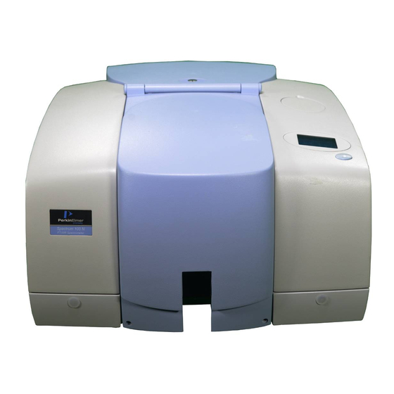
Spectrum 100 and 400 Series
R ight-hand Ex ternal Beam Option
Spectrum 100 and 400 Series instruments can be fitted with a Right-hand External Beam
Option.
The Right-hand External Beam Option includes: a right-hand beam moveable mirror fitted
within in the spectrometer, a KBr window, and an external accessory bracket fitted in the
handhold on the right of the instrument. The bracket allows you to attach and use a pre-
amplifier and detector of your choice.
Figure 1 Handhold with external accessory bracket fitted
This document describes how to:
Fit a different window in the right-hand external beam port.
•
•
Connect a third-party pre-amplifier and detector to the instrument.
•
Configure Spectrum or Spectrum Express software to use a third-party external
detector.
•
Use Spectrum or Spectrum Express software to select the accessory.
NOTE: The Right-hand External Beam Option is installed, in the first instance, by a
PerkinElmer Service Engineer, who will install the external accessory bracket in the
handhold on the right of the instrument (if not already fitted) and any internal parts
required. This external accessory bracket should not be removed.
PerkinElmer Ltd, Chalfont Road, Seer Green,
Beaconsfield, BUCKS, HP9 2FX, United Kingdom.
L1050069A
Produced in the UK.
Advertisement
Table of Contents


Need help?
Do you have a question about the Spectrum 100 Series and is the answer not in the manual?
Questions and answers