PerkinElmer LAMBDA 265 User Manual
Hide thumbs
Also See for LAMBDA 265:
- User manual (61 pages) ,
- Installation instructions manual (32 pages) ,
- Assembly/installation instructions (18 pages)

Subscribe to Our Youtube Channel
Related Manuals for PerkinElmer LAMBDA 265


Summary of Contents for PerkinElmer LAMBDA 265
- Page 1 UV SPECTROMETERS 265, 365 AMBDA ASX-260/280 ASX- 520/560 A UTOSAMPLER Users Guide...
- Page 2 The information contained in this document is subject to change without notice. Except as specifically set forth in its terms and conditions of sale, PerkinElmer makes no warranty of any kind with regard to this document, including, but not limited to, the implied warranties of merchantability and fitness for a particular purpose.
-
Page 3: Table Of Contents
Contents . 3 Table of Contents Introduction ..................5 Features ....................6 Autosamplers and Peristalic Pump ............7 Dimensions and Specifications ..............8 Dimensions of AutoSampler .............. 8 Specifications of Peristaltic Pump ............8 ... - Page 4 4 . Lambda 265, 365 and 465 ASX-260/280 AND ASX-520/560 Autosampler Users Guide...
-
Page 5: Introduction
Introduction... -
Page 6: Features
6 . Lambda 265, 365 and 465 ASX-260/280 AND ASX-520/560 Autosampler Users Guide Features The ASX 260/280 and ASX-520/560 autosamplers are designed to be study, reliable and easy to use. They provide automated sample introduction that enables you to perform other tasks while the Auto Sampler runs. -
Page 7: Autosamplers And Peristalic Pump
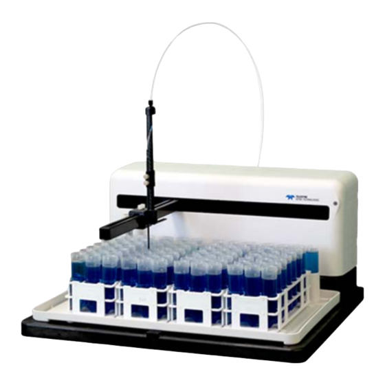
Autosamplers and Peristalic Pump Autosampler (ASX-260) Autosampler (ASX-520) Autosampler (ASX-280) Autosampler (ASX-560) Peristaltic Pump... -
Page 8: Dimensions And Specifications
8 . Lambda 265, 365 and 465 ASX-260/280 AND ASX-520/560 Autosampler Users Guide Dimensions and Specifications Dimensions of AutoSampler Specification Physical Characteristic ASX-260 ASX-520 Power 100-240 VAC, 47/63 Hz Dimensions (mm) 330 (W) x 508 (D) x 610 (H) 520 (W) x 482 (D) x 610 (H) Weight (kg) 10.5... -
Page 9: Safety Summary
Safety Summary The following safety symbols are used on this product. Warning Description Always refer to the system manual when working near locations at which the alert mark shown on the left is attached. If the operation, etc., is performed without heeding the advice in the System manual, there is a risk of personal injury. - Page 10 10 . Lambda 265, 365 and 465 ASX-260/280 AND ASX-520/560 Autosampler Users Guide “OFF” (power) To indicate disconnection from the mains, at least for mains switches or their positions, and all those case where safety is involves. "OFF" (Hors tension)
- Page 11 Warning Description Keep the equipment free of dust. Clean the power line regularly; if dust accumulates around the power pins, there is a risk of fire. Keep the equipment clean so that the ventilation holds are not obstructed. If the ventilation is obstructed, the system may overheat and catch fire.
-
Page 12: Conventions Used In This Manual
12 . Lambda 265, 365 and 465 ASX-260/280 AND ASX-520/560 Autosampler Users Guide Conventions Used in this Manual Normal text is used to provide information and instructions. Bold text refers to text that is displayed on the screen. UPPERCASE text, for example ENTER or ALT, refers to keys on the PC keyboard. '+' is used to show that you have to press two keys at the same time, for example, ALT+F. - Page 13 We use the term CAUTION to inform you about situations that CAUTION could result in serious damage to the instrument or other equipment. Details about these circumstances are in a box like this one. Caution (Achtung) Bedeutet, daß die genannte Anleitung genau befolgt werden muß, um einen Geräteschaden zu vermeiden.
- Page 14 14 . Lambda 265, 365 and 465 ASX-260/280 AND ASX-520/560 Autosampler Users Guide We use the term WARNING to inform you about situations that could result in personal injury to yourself or other persons. Details about these circumstances are in a box like this one.
-
Page 15: Contact Us
If you are located within the U.S., call toll free 1-800-762-4000, 8 a.m. to 8 p.m. EST. Your order will be shipped promptly, usually within 24 hours. If you are located outside of the U.S., call your local PerkinElmer sales or service office. - Page 16 16 . Lambda 265, 365 and 465 ASX-260/280 AND ASX-520/560 Autosampler Users Guide...
-
Page 17: Description
Description... -
Page 18: Description Of The Autosampler
18 . Lambda 265, 365 and 465 ASX-260/280 AND ASX-520/560 Autosampler Users Guide Description of the Autosampler Front View of Autosampler A) Sample tray The sample tray holds the rinse station, sample racks, and standards vials in place. The tray also contains small spills. -
Page 19: Back View Of Autosampler
Description. 19 Back View of Autosampler A) Peristaltic pump A two-channel peristaltic pump moves the rinse solution from the rinse source through the flowing rinse station. B) Serial Ports The COM1 port connects the autosampler with the analytical instrument’s host computer. -
Page 20: Description Of The Peristaltic Pump
20 . Lambda 265, 365 and 465 ASX-260/280 AND ASX-520/560 Autosampler Users Guide Description of the Auto sipper Peristaltic Pump for Lambda 265/365/465 Lambda 265/465 Tube connection components for Lambda 265/465 Conical Outlet tube Adapter (1ea) (2ea) Peristaltic Inlet tube... - Page 21 Description. 21 Lambda 365 Tube connection components Conical Outlet tube Adapter (1ea) (2ea) Peristaltic Inlet tube pump tube (1ea) (1ea) Tube 1.5 M Flow cell (1ea) (1ea) Beam height: L365(15 mm) Flow cell for L365 P/N: N4101052 Front plate for Auto Sipper accessory [P/N: N4101026] Connection Flangeless Tube...
- Page 22 22 . Lambda 265, 365 and 465 ASX-260/280 AND ASX-520/560 Autosampler Users Guide Optional autosampler accessory for the connecting to Lambda 265/365/465 Union and ferrule kit are used to connect between autosampler and auto sipper. connection kit This kit is optional and must be purchased separately...
-
Page 23: Installation
Installation... -
Page 24: Installation
24. Lambda 265, 365 and 465 ASX-260 AND ASX-520 Autosampler Users Guide Installation 1. Place the Lambda 265/365/465 autosampler (ASX-260/280 or 520/560) and peristaltic pump in a location that is compatible with the required environmental conditions for the operation. 2. Connect the communication cable and the power cord to each system and PC. - Page 25 Installation 25 Tube line installation for Lambda 265 and 465 1. Assemble one of the flangeless fittings in the union and ferrule kit and connect it to the tube of the autosampler probe. 2. Prepare the tube connection components and assemble each component one by one.
- Page 26 26. Lambda 265, 365 and 465 ASX-260 AND ASX-520 Autosampler Users Guide Connection C: Connect the tube to the conical adapter, and to the peristaltic pump tube. Insert the peristaltic pump tubing into the cassette by placing the fixing collars of the peristaltic pump tubing in the holes on each side of the cassette.
- Page 27 The inlet tube is connected to the port of the flow cell with the arrow mark and the outlet tube is connected to the other port of the flow cell. Put the flow cell into the cell holder. 7. System configuration for the autosampler connection to the Lambda 265/465.
- Page 28 28. Lambda 265, 365 and 465 ASX-260 AND ASX-520 Autosampler Users Guide Tube line installation for Lambda 365 1. Assemble the flangeless fitting in the union and ferrule kit and connect it to the tube of the autosampler probe. 2. Prepare the tube connection components and the front plate for Auto Sipper accessory and assemble each component one by one.
- Page 29 Installation 29 Connection C: Connect the Flangeless fitting of the Connection tube assembly to the front plate. Assemble the Flangeless fitting for Connection A and Connection B following the procedures NOTE: in the picture below. Flangeless fitting Connection D: Connect the conical adapter of the Connection tube assembly to the peristaltic pump tubing.
- Page 30 30. Lambda 265, 365 and 465 ASX-260 AND ASX-520 Autosampler Users Guide 3. Press the cassette down to lock the right side snap lever on the locking bar. 4. Connect to the flangeless fittings to the inlet and outlet tubes for the flow cell.
- Page 31 Installation 31 6. Remove the two Phillips round head screws with washer (M4*12L) to disassemble the existing cell holder and base plate. And then insert the front plate for Auto Sipper accessory in the sample compartment. 7. Tighten the front plate for Auto sipper accessory in the sample compartment with the screws and insert the single cell holder on the front plate and tight the knob.
- Page 32 32. Lambda 265, 365 and 465 ASX-260 AND ASX-520 Autosampler Users Guide 8. Put the empty flow cell into the cell holder. 9. System configuration for the autosampler connection to the Lambda 365. 10. To start the measurement, turn on the power for the instrument, peristaltic pump...
-
Page 33: Interface Setup
Interface Setup... -
Page 34: Installing The Driver Of Lambda 465
34 . Lambda 265, 365 and 465 ASX-260/280 AND ASX-520/560 Autosampler Users Guide Installing the Driver of Lambda 465 In case of the Lambda 265/365, Driver has already been installed when installing the NOTE : software, user does not need to install it again. - Page 35 Interface Setup. 35 8. The following dialog box will appear. After installation is completed successfully select Finish. 9. Change the USB serial ports after finishing driver setup referring to the following chapter.
-
Page 36: Setting Usb Serial Ports
36 . Lambda 265, 365 and 465 ASX-260/280 AND ASX-520/560 Autosampler Users Guide Setting USB Serial Ports 1. Select Computer →Properties. 2. Select Device Manager. - Page 37 Interface Setup. 37 3. Select the Ports (COM & LPT) to expand the listing. These are the devices currently connected to the COM ports. USB Serial Port (COMx) is visible when the driver installation is completed successfully. 4. Double click USB Serial Port (COMx) of the Ports (COM & LPT) section.
- Page 38 38 . Lambda 265, 365 and 465 ASX-260/280 AND ASX-520/560 Autosampler Users Guide 5. Select on the Port Settings tab and select the Advanced… button. 6. Change the parameter values as shown below. 1024 1024...
- Page 39 Interface Setup. 39 7. Select OK after checking the changed parameter values. 8. Launch the software. 9. If the instrument fails to communicate with the PC, change the COM Port Number referring to the following procedures. Setting 10. Open the Advanced Setting for COMx window, following the procedure of USB Serial Ports on page 36.
- Page 40 40 . Lambda 265, 365 and 465 ASX-260/280 AND ASX-520/560 Autosampler Users Guide 12. Make sure that the changed COM Port Number is applied and select OK. 13. Restart the computer after finishing driver setting.
-
Page 41: Uv Lab Software
UV Lab Software... -
Page 42: Wavelength Monitoring Measurement Procedure
42 Lambda 265, 365 and 465 ASX-260/280 AND ASX-520/560 Autosampler Users Guide Wavelength Monitoring Measurement Procedure In case of Lambda 465, start the sample measurement after warming up the system at least NOTE: 20 minutes. 1. Launch the UV Lab Software and then select Wavelength Monitoring and click OK. - Page 43 UV Lab Software. 43 5. The Autosampler setup box will be shown. Set each parameter according to the experiment conditions. a. Autosampler (ASX-260/280) b. Autosampler (ASX-520/560) 1) Auto Sampler Setting...
- Page 44 44 Lambda 265, 365 and 465 ASX-260/280 AND ASX-520/560 Autosampler Users Guide ▶ Sample Rack Type The following different types are available. Select the desired sample rack type. 1) 30 mm tubes (3 x 7 Positions) 2) 25 mm tubes (3 x 8 Positions)
- Page 45 UV Lab Software. 45 ▶ Stabilizing Time (sec) To make stabilization after the blank or sample solution is filled up the cell, enter the suitable stabilizing time. If the time is set as '0', it will be scanned directly without the stabilization. ▶...
- Page 46 46 Lambda 265, 365 and 465 ASX-260/280 AND ASX-520/560 Autosampler Users Guide 8. Click Blank icon. 9. The probe will move to the blank position and start sucking, and after filling up the flow cell, the blank will be measured.
-
Page 47: Quantification Measurement Procedure
UV Lab Software. 47 Quantification Measurement Procedure In case of Lambda 465, start the sample measurement after warming up the system at least NOTE: 20 minutes. Execute the UV Lab Software and then select Quantification Standard and click After setting parameters for Experiment Setup, Baseline Correction and Quantification Standard, click OK. - Page 48 48 Lambda 265, 365 and 465 ASX-260/280 AND ASX-520/560 Autosampler Users Guide The autosampler setup box will be shown. Set each parameter according to the experiment conditions. a. Autosampler (ASX-260/280) b. Autosampler (ASX-520/560) 1) Auto Sampler Setting...
- Page 49 UV Lab Software. 49 ▶ Sample Rack Type The following different types are available. Select the desired sample rack type. 1) 30 mm tubes (3 x 7 Positions) 2) 25 mm tubes (3 x 8 Positions) 3) 20 mm tubes (4 x 10 Position) 4) 15 mm tubes (5 x 12 Position) 5) 13 mm tubes (6 x 15 Position) ▶...
- Page 50 50 Lambda 265, 365 and 465 ASX-260/280 AND ASX-520/560 Autosampler Users Guide ▶ Stabilizing Time (sec) To make stabilization after the blank or sample solution is filled up the cell, enter the suitable stabilizing time. If the time is set as '0', it will be scanned directly without the stabilization.
- Page 51 UV Lab Software. 51 Click Blank. The probe will move to the blank position and start sucking and, after filling up the flow cell, the blank will be measured. 10. Click Standard. User can set up to 10 standard samples in the Autosampler. The number of standards NOTE: should be matched with the number of concentration entry in the Quantification Standard set-up windows.
- Page 52 52 Lambda 265, 365 and 465 ASX-260/280 AND ASX-520/560 Autosampler Users Guide...
-
Page 53: Uv Express Software
UV Express Software... -
Page 54: Scan And Wavelength Program Mode Measurement Procedure
54 . Lambda 265, 365 and 465 ASX-260/280 AND ASX-520/560 Autosampler Users Guide Scan and Wavelength Program Mode Measurement Procedure Auto Sampler accessory is available to be controlled in Scan, Wavelength Program, NOTE: Quantification and Scanning Quantification mode of UV Express software. - Page 55 UV Express Software 55 Select the Auto Sampler model (ASX-260/280, as example). Click OK. The Auto Sampler setup box will be shown. Set each parameter according to the experiment conditions. 1) Auto Sampler Setting ▶ Sample Rack Type The following different types are available. Select the desired sample rack type. 1) 30 mm tubes (3 x 7 Positions) 2) 25 mm tubes (3 x 8 Positions) 3) 20 mm tubes (4 x 10 Position)
- Page 56 56 . Lambda 265, 365 and 465 ASX-260/280 AND ASX-520/560 Autosampler Users Guide ▶ COM Port No.: Click Port Find. The COM port no. will be selected automatically. ▶ Blank Position: Select the blank position. ▶ Sample Position Samples are measured form Start Position to End Position in order.
- Page 57 UV Express Software 57 ▶ Washing Time after Sampling (sec) To clean the tube & flow cell after the measurement, you need to set the washing time. After all set-up, Click Download before measurement. ▶ Download: ▶ Run: Click Run to check if the peristaltic pump is working as set. ▶...
- Page 58 58 . Lambda 265, 365 and 465 ASX-260/280 AND ASX-520/560 Autosampler Users Guide 11. Insert reference sample in the Reference cell holder. Reference Sample 12. Insert reference sample in the set Blank Position (e.g. position 1) and sample in each position of the Autosampler sample racks.
-
Page 59: Quantification And Scanning Quantification Mode Measurement Procedure
UV Express Software 59 Quantification and Scanning Quantification Mode Measurement Procedure Start the System Seflf Test after more than 20 minutes warming-up of the system. NOTE: Double-click UV Express folder and select Quantification (or Scanning Quantification) modes for starting. The following window will be shown. Empty the cell holder and close the lid firmly. When performing System Self Test, both reference and sample cell holder have to be emptied. - Page 60 60 . Lambda 265, 365 and 465 ASX-260/280 AND ASX-520/560 Autosampler Users Guide Select the Auto sampler model. Click OK. The Autosampler setup box will be shown. Set each parameter according to the experiment conditions. 1) Auto Sampler Setting ▶ Sample Rack Type The following different types are available.
- Page 61 UV Express Software 61 ▶ COM Port No.: Click Port Find. The COM port no. will be selected automatically. ▶ Blank Position: Select the blank position. ▶ Sample Position Samples are measured form Start Position to End Position in order. - Start: Select the first sample vial for measurement.
- Page 62 62 . Lambda 265, 365 and 465 ASX-260/280 AND ASX-520/560 Autosampler Users Guide To make stabilization after the blank or sample solution is filled up the cell, enter the suitable stabilizing time. It recommends more than 20 sec. If the time is set as '0', it will be scanned directly without the stabilization.
- Page 63 UV Express Software 63 11. Insert reference sample in the reference cell holder. Reference Sample Insert the standard samples in the autosampler standard rack. 13. Insert reference sample in the set Blank Position (e.g. position 1) and samples in each position of the Autosampler sample racks.
- Page 64 64 . Lambda 265, 365 and 465 ASX-260/280 AND ASX-520/560 Autosampler Users Guide 14. Click Baseline. 15. The probe will move to the Blank position and start sucking, and after filling up the flow cell, the Baseline will be measured.
-
Page 65: Maintenance
Maintenance... -
Page 66: Maintenance
66 . Lambda 265, 365 and 465 ASX-260/280 AND ASX-520/560 Autosampler Users Guide Maintenance The tube for transportation of solution to peristaltic pump and autosampler is flexible and prone to tear, so this tube needs to be replaced periodically. The replacement period depends on the tubing shape, material, diameter and used time.
Need help?
Do you have a question about the LAMBDA 265 and is the answer not in the manual?
Questions and answers