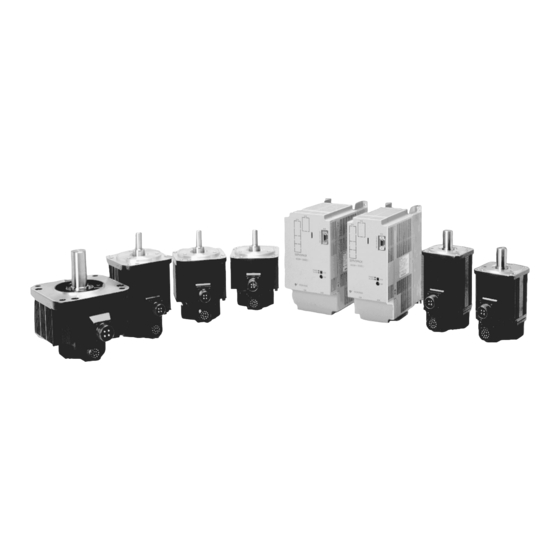
YASKAWA SGM Series User Manual
Hide thumbs
Also See for SGM Series:
- User manual (430 pages) ,
- Safety precautions (35 pages) ,
- Manual (196 pages)
Table of Contents
Advertisement
Advertisement
Table of Contents

Related Manuals for YASKAWA SGM Series


Summary of Contents for YASKAWA SGM Series
- Page 1 YASKAWA YASKAWA MANUAL NO. SIE-S800-26.4B...
- Page 2 Yaskawa. No patent liability is assumed with respect to the use of the information contained herein. Moreover, because Yaskawa is constantly striving to improve its high-quality products, the information contained in this manual is subject to change without notice.
-
Page 3: Overview
OVERVIEW OVERVIEW Overview ..........Safety Precautions . - Page 4 5.8 Appropriate Applications ....... . . 5 -18 5.9 Adjustments .
-
Page 5: Table Of Contents
TABLE OF CONTENTS TABLE OF CONTENTS Overview ............Safety Precautions . - Page 6 3.4 Large-amplitude Frequency Characteristics ....3 -6 3.5 Mechanical Characteristics ....... . . 3 -7 3.5.1 Mechanical Strength .
- Page 7 TABLE OF CONTENTS Application 5.1 Turning Power ON/OFF ........5 -3 5.2 Position Control .
- Page 8 6.4 Special Descriptions ........6 -7 6.4.1 Option Field Specifications .
- Page 9 TABLE OF CONTENTS 8.3 Wiring Specifications ........8 -7 8.3.1 Rated Current and Cable Specifications .
- Page 10 10 Trial Operation 10.1 Check Items before Trial Operation ......10 -2 10.1.1 Servomotors ............10 -2 10.1.2 SERVOPACKS .
- Page 11 Based on Yaskawa servo manufacturing technology and servo application technology accumulated over the last half a century, Yaskawa has launched the AC Servo Series that, together with its rich line of products, meets the needs of the modern needs of FA and FMS in their application to machin- ing tools and robots.
-
Page 12: Safety Precautions
Safety Precautions The following precautions are for checking products upon delivery, installation, wiring, operation, maintenance and inspections. J Checking Products on Delivery CAUTION D Be sure to use the specified Servomotor and SERVOPACK combination. Fire or damage may result if the wrong combination is used.. J Installation CAUTION D Do not use the products in or near environments exposed to moisture, corrosive gases, flammable... - Page 13 Safety Precautions J Operation WARNING D Do not touch rotating parts of the Servomotor during operation. Injury may result. CAUTION D In order to avoid accidents, do not connect the Servomotor shaft to the controlled equipment dur- ing the trial operation. Injury may result.
- Page 14 The edition number appears on the front and back covers. S If the manual must be ordered due to loss or damage, inform your nearest Yaskawa representa- tive or one of the offices listed on the back of this manual.
-
Page 15: Configuration And Models
Configuration and Models This chapter describes the configuration and model numbers for Servo- drives. 1.1 Configuration ......1 - 2 1.2 Model Numbers . -
Page 16: Configuration
Configuration and Models 1.2.1 Servomotor Model Numbers 1.1 Configuration Servodrives are configured using a SERVOPACK (Controller) and Servomotors. D SGDB-jjAN SERVOPACK D AC Servomotor 1.2 Model Numbers 1.2.1 Servomotor Model Numbers J SGMP Servomotors SGMP - 15 A 3 1 2 j Options Σ-Series B: With brake... - Page 17 1.2 Model Numbers J SGMG/SGMS/SGMD Servomotors SGMj - 03 A 2 A A j j Lead Specification Σ-Series Blank: Standard connector SGMG: SGMG Servomotor SGMS: SGMS Servomotor Options SGMD: SGMD Servomotor Blank:Standard 1: Standard Servomotor Capacity (with a lead specification) 03: 0.3 kW, 05: 0.45 kW, 06: 0.6 kW S: With shaft seal 09: 0.85 kW/0.9 kW, 10: 1.0 kW...
-
Page 18: Servopack Model Numbers
Configuration and Models 1.2.2 SERVOPACK Model Numbers 1.2.2 SERVOPACK Model Numbers SGDB - 10 A N - j Options Σ-Series P: Duct ventilation SGDB SERVOPACK Rated Output 05: 0.5 kW, 10: 1.0 kW, 15: 1.5 kW Command Interface Type 20: 2.0 kW, 30: 3.0 kW, 50: 5.0 kW N: MECHATROLINK 60: 6.0 kW, 75: 7.5 kW, 1A: 11.0 kW 1E: 15.0 kW... -
Page 19: Ratings And Characteristics
Ratings and Characteristics This chapter provides Servodrive ratings, specifications, and torque-speed characteristics. For SGM Servomotors (400 W, 750 W) and SGMP Servomotors (400 W, 750 W), refer to “Σ Series SGM/SGMP/SGD-jN USER’S MANUAL” (SIE-S800-26.3). 2.1 Ratings and Specifications of SGMG Servomotors for Rated Speed 1500 r/min . -
Page 20: Ratings And Specifications
Ratings and Characteristics 2.1.1 Ratings and Specifications 2.1 Ratings and Specifications of SGMG Servomotors for Rated Speed 1500 r/min 2.1.1 Ratings and Specifications S Time Rating: Continuous S Ambient Temperature: 0 to 40°C S Enclosure: Totally enclosed, self cooled, S Mounting: Flange method IP67 (except shaft-through section) S Excitation: Permanent magnet S Withstand Voltage: 1500 VAC... - Page 21 2.1 Ratings and Specifications of SGMG Servomotors for Rated Speed 1500 r/min Servomotor Model: 05AjA 09AjA 13AjA 20AjA 30AjA 44AjA 55AjA 75AjA 1AAjA 1EAjA SGMG- Inertia Time 0.98 Constant Inductive 12.5 12.5 15.7 16.4 18.4 22.6 27.2 Time Constant * 1. These items and torque-motor speed characteristics are in combination with an SGDB SERVOPACK and at an armature winding temperature of 20_C.
- Page 22 Ratings and Characteristics 2.1.1 Ratings and Specifications J SGMG Servomotor (Rated Motor Speed of 1500 r/min) Torque-Motor Speed Characteristics SGMG-05AjA SGMG-09AjA Motor Motor speed speed (r/min) (r/min) Torque (N⋅m) Torque (N⋅m) Torque (lb⋅in) Torque (lb⋅in) SGMG-13AjA SGMG-20AjA Motor Motor speed speed (r/min) (r/min)
- Page 23 2.1 Ratings and Specifications of SGMG Servomotors for Rated Speed 1500 r/min SGMG-55AjA SGMG-75AjA Motor Motor speed speed (r/min) (r/min) Torque (N⋅m) Torque (N⋅m) 1000 Torque (lb⋅in) Torque (lb⋅in) SGMG-1AAjA SGMG-1EAjA Motor Motor speed speed (r/min) (r/min) Torque (N⋅m) Torque (N⋅m) 1000 1500 Torque (lb⋅in)
-
Page 24: Ratings And Specifications Of Sgmg Servomotors For Rated Speed 1000 R/Min
Ratings and Characteristics 2.2.1 Ratings and Specifications 2.2 Ratings and Specifications of SGMG Servomotors for Rated Speed 1000 r/min 2.2.1 Ratings and Specifications S Time Rating: Continuous S Ambient Temperature: 0 to 40°C S Enclosure: Totally enclosed, self cooled, S Mounting: Flange method IP67 (except shaft-through section) S Excitation: Permanent magnet S Withstand Voltage: 1500 VAC... - Page 25 2.2 Ratings and Specifications of SGMG Servomotors for Rated Speed 1000 r/min The ratings and specifications shown on the previous page are for standard Servomotors. IMPORTANT For Servomotors with holding brakes, add the values in the following table to the moment of inertia values in the above table.
- Page 26 Ratings and Characteristics 2.2.1 Ratings and Specifications J SGMG Servomotor (Rated Motor Speed of 1000 r/min) Torque-Motor Speed Characteristics SGMG-03AjB SGMG-06AjB Motor Motor speed speed (r/min) (r/min) Torque (N⋅m) Torque (N⋅m) Torque (lb⋅in) Torque (lb⋅in) SGMG-09AjB SGMG-12AjB Motor Motor speed speed (r/min) (r/min)
- Page 27 2.2 Ratings and Specifications of SGMG Servomotors for Rated Speed 1000 r/min SGMG-44AjB SGMG-60AjB Motor Motor speed speed (r/min) (r/min) Torque (N⋅m) Torque (N⋅m) 1000 1000 Torque (lb⋅in) Torque (lb⋅in) Continuous Duty Zone Intermittent Duty Zone 2 -9...
-
Page 28: Sgms Servomotor Ratings And Specifications
Ratings and Characteristics 2.3.1 Ratings and Specifications 2.3 SGMS Servomotor Ratings and Specifications 2.3.1 Ratings and Specifications S Time Rating: Continuous S Ambient Temperature: 0 to 40°C S Enclosure: Totally enclosed, self cooled, S Mounting: Flange method IP67 (except shaft-through section) S Excitation: Permanent magnet S Withstand Voltage: 1500 VAC S Insulation Class: Class F... - Page 29 2.3 SGMS Servomotor Ratings and Specifications The ratings and specifications shown on the previous page are for standard Servomotors. IMPORTANT For Servomotors with holding brakes, add the values in the following table to the moment of inertia values in the above table. Other characteristics may also change. Servomotor Model: SGMG 10AjA 15AjA...
- Page 30 Ratings and Characteristics 2.3.1 Ratings and Specifications J SGMS Servomotor Torque Motor Speed Characteristics SGMS-10AjA SGMS-15AjA Motor Motor speed speed (r/min) (r/min) Torque (N⋅m) Torque (N⋅m) Torque (lb⋅in) Torque (lb⋅in) SGMS-20AjA SGMS-30AjA Motor Motor speed speed (r/min) (r/min) Torque (N⋅m) Torque (N⋅m) Torque (lb⋅in) Torque (lb⋅in)
-
Page 31: Sgmd Servomotor Ratings And Specifications (With Holding Brake)
2.4 SGMD Servomotor Ratings and Specifications (with Holding Brake) 2.4 SGMD Servomotor Ratings and Specifications (with Holding Brake) 2.4.1 Ratings and Specifications S Time Rating: Continuous S Ambient Temperature: 0 to 40°C S Enclosure: Totally enclosed, self cooled, S Mounting: Flange method IP67 (except shaft-through section) S Excitation: Permanent magnet S Withstand Voltage: 1500 VAC... -
Page 32: Ratings And Specifications
Ratings and Characteristics 2.4.1 Ratings and Specifications J SGMD Servomotor Torque Motor Speed Characteristics SGMD-22AjAAB SGMD-32AjAAB Motor Motor speed speed (r/min) (r/min) Torque (N⋅m) Torque (N⋅m) Torque (lb⋅in) Torque (lb⋅in) SGMD-40AjAAB Motor speed (r/min) Torque (N⋅m) Torque (lb⋅in) Continuous Duty Zone Intermittent Duty Zone 2 -14... -
Page 33: Sgmp Servomotor (1.5 Kw) Ratings And Specifications
2.5 SGMP Servomotor (1.5 kW) Ratings and Specifications 2.5 SGMP Servomotor (1.5 kW) Ratings and Specifications 2.5.1 Ratings and Specifications S Time Rating: Continuous S Ambient Temperature: 0 to 40°C S Enclosure: Totally enclosed, self cooled S Mounting: Flange method S Excitation: Permanent magnet S Withstand Voltage: 1500 VAC per 1 min S Insulation Class: Class B... - Page 34 Ratings and Characteristics 2.5.1 Ratings and Specifications Servomotor Model: SGMG −4 × 10 0.875 With Added ⋅ Holding Holding Moment Moment −3 12.4 oz⋅in⋅s × Brake, of Inertia 90 VDC 90 VDC 7.45 Static ⋅ (1055) Friction ⋅ Torque J SGMP Servomotor (1.5 kW) Torque Motor Speed Characteristics SGMP-15A Motor speed...
-
Page 35: Servopack Ratings And Specifications
2.6 SERVOPACK Ratings and Specifications 2.6 SERVOPACK Ratings and Specifications 2.6.1 Ratings and Specifications The ratings and specifications for the SGDB SERVOPACK are shown below. Refer to them as re- quired when selecting a SERVOPACK. Refer to the specifications listed in the table for combination with the appropriate model of Servomotor. - Page 36 Ratings and Characteristics 2.6.1 Ratings and Specifications SERVOPACK SGDB- Monitoring Using the monitor command, monitoring of various positions, speeds, position error torque, SERVOPACK status, and alarm contents is possible. I/O Sig- Sequence Inputs Forward overtravel prohibit (P-OT), reverse overtravel prohibit (N-OT), external nals latch (EXT), and zero point return deceleration limit switch (DEC) Sequence Outputs...
-
Page 37: Combined Specifications
2.7 Combined Specifications 2.7 Combined Specifications The following specifications for combinations of SGDB SERVOPACKS and SGMG, SGMS, SGMD and SGMP Servomotors. 2.7.1 Standard Combinations Table 2.7 SERVOPACK and Servomotor Combination Specifications. SGMG SERVOPACK Model 05AN 10AN 15AN 20AN 30AN 50AN 60AN SGDB- Series... - Page 38 Ratings and Characteristics 2.7.1 Standard Combinations SGMD SERVOPACK Model 30AN 50AN SGDB- Series Series Appli- Model SGMD- 22AjA 32AjA 40AjA cable Motor Servo- Capacity (kW) motor Rated/Max. 2000/3000 r/min Motor Speed Applicable Standard: Absolute encoder at 1024 P/R Encoder Allowable Load Inertia* (3611) (4857)
- Page 39 2.7 Combined Specifications SERVOPACK Model SGDB- 10AN 15AN 20AN 30AN 50AN Appli- Model SGMS- 10AjA 15AjA 20AjA 30AjA 40AjA 50AjA cable Motor Capacity Servo- (kW) motor motor Rated/Max. Motor 3000/4500 r/min Speed Applicable Encoder Standard: Incremental encoder at 4096 P/R Allowable Load 12.4 (176) 16.0 (227)
-
Page 40: Peripheral Device Combinations
* 2. Shut off characteristics (at 25°C): 200%: 2 s min., 700%: 0.01 s min. * 3. A Tokin Corp. noise filter or a SCHAFFNER noise filter (FN258-100) is recommended. Tokin Corp. noise fil- ters are available from Yaskawa Control Co,. 2 -22... -
Page 41: Servodrive Characteristics
Servodrive Characteristics This chapter provides information on the characteristics of SERVOPACKS 3.1 Overload Characteristics ....3 -2 3.2 Starting and Stopping Time . -
Page 42: Overload Characteristics
Servodrive Characteristics 3.1 Overload Characteristics The SERVOPACK has a built-in overload protective function to protect the SERVOPACK and Ser- vomotor from overload. Allowable power for the SERVOPACK is therefore limited by the overload protective function as shown in Fig. 3.1. The overload detection level quoted under hot start conditions at a motor ambient temperature of 40°C cannot be modified. -
Page 43: Starting And Stopping Time
3.2 Starting and Stopping Time 3.2 Starting and Stopping Time The motor starting (tr) and stopping time (tf) with a constant load are calculated using the following equations. Motor viscous torque and friction torque have been ignored. Starting time: tr = 104.7 × [ms] Kt ⋅... -
Page 44: Allowable Repeatability
Servodrive Characteristics 3.3.1 Allowable Repeatability as Limited by the Servomotor 3.3 Allowable Repeatability Running and stopping repeatability are limited by the Servomotor. 3.3.1 Allowable Repeatability as Limited by the Servomotor Running and stopping repeatability vary with motor conditions, such as the load conditions and running time. - Page 45 3.3 Allowable Repeatability Motor current Time Motor speed Time Figure 3.4 Motor Current - Motor Speed Timing Chart J With Motor Constantly Cycling through Acceleration, Idling, and Deceleration without Stopping The timing chart for motor armature current and motor speed is shown in Fig 3.5. If we assume that allowable repeatability is n (times per minute), then n can be found using the equation given below.
-
Page 46: Large-Amplitude Frequency Characteristics
Servodrive Characteristics 3.4 Large-amplitude Frequency Characteristics When looking at frequency characteristics with a SERVOPACK and Motor combination, the motor speed amplitude is limited by the peak current through the SERVOPACK. The relationship between motor speed (N) and frequency (f) is expressed using the equation given below. α... -
Page 47: Mechanical Characteristics
3.5 Mechanical Characteristics 3.5 Mechanical Characteristics 3.5.1 Mechanical Strength An AC Servomotor can withstand instantaneous peak torque on the output shaft of up to 300% of the motor rating. 3.5.2 Allowable Radial and Thrust Load The output shaft allowable loads of AC Servomotors are shown below. Use mechanical designs where thrust and radial loads do not exceed the values below during mo- tor operation. -
Page 48: Mechanical Tolerances
Servodrive Characteristics 3.5.5 Impact Resistance Note Radial and thrust load limit value are the sum of the loads generated by the motor torque and external loads applied to the shaft. 3.5.3 Mechanical Tolerances Tolerances for AC Servomotor output shaft and installation are shown in Table 3.2. Table 3.2 Mechanical Tolerances Tolerance (T.I.R.) -
Page 49: Vibration Resistance
3.5 Mechanical Characteristics D Number of Impacts: 2 Since a precision detector is attached to the shaft at the end opposite the load end, do not subject the shaft to direct impact as this may damage the encoder. Vertical Horizontal shaft Figure 3.8 Impact Measurement 3.5.6 Vibration Resistance... -
Page 50: Configuration And Connections
Configuration and Connections This chapter provides information on the configuration and connections of Servodrives. 4.1 Internal Connection Diagram ....4 -3 4.1.1 0.5 kW to 1.5 kW Servodrives . - Page 51 Configuration and Connections 4.8 2CN Encoder Connector Terminals ..4 -22 4.8.1 2CN Terminal Layout ......4 -22 4.8.2 Applicable Cables .
-
Page 52: Internal Connection Diagram
4.1 Internal Connection Diagram 4.1 Internal Connection Diagram 4.1.1 0.5 kW to 1.5 kW Servodrives + 10 Three-phase 200 to 230 VAC –15 %, (50/60 Hz) Servomotor Line filter Base driver and overcurrent protection isolator Voltage Voltage Relay detection detection drive isolator isolator... -
Page 53: Kw To 3.0 Kw Servodrives
Configuration and Connections 4.1.2 2.0 kW to 3.0 kW Servodrives 4.1.2 2.0 kW to 3.0 kW Servodrives + 10 Three-phase 200 to 230 VAC –15 %, (50/60 Hz) * 2.0 kW with- out FAN2 Servomotor Line filter Base driver and overcurrent protection isolator Voltage Relay... -
Page 54: Kw Servodrive
4.1 Internal Connection Diagram 4.1.3 5.0 kW Servodrive + 10 Three-phase 200 to 230 VAC –15 %, (50/60 Hz) Servomotor Line filter Base driver and overcurrent Voltage protection isolator Relay Voltage detection detection iso- drive isolator lator Gate drive isolator Encoder Current detec-... -
Page 55: Kw To 15.0 Kw Servodrives
Configuration and Connections 4.1.4 6.0 kW to 15.0 kW Servodrives 4.1.4 6.0 kW to 15.0 kW Servodrives Regenerative resistor (optional) + 10 Three-phase 200 to 230 VAC –15 %, (50/60 Hz) Servomotor Line filter Base driver and overcurrent Voltage protection isolator Relay Voltage detection... -
Page 56: Name And Description Of Main Circuit Terminals
Case Manufacturer Connector 10220-52A2JL (Product of 10120-3000VE 10320-52A0-008 SUMITOMO 3M Co., See 9.3 “Cables”. SUMITOMO 3M Co.,Ltd.), Ltd. 20 pin right angle Note This cable is available from Yaskawa. Refer to 9.3 “Cables” for more details on cables. 4 -7... -
Page 57: 4Cn Connector For Mechatrolink Communication
Configuration and Connections 4.3.3 4CN Connector for MECHATROLINK Communication 4.3.3 4CN Connector for MECHATROLINK Communication Table 4.4 Applicable Receptacle Specifications for Applicable Receptacle Model SERVOPACK C SERVOPACK Connector Solder Case Manufacturer MR-8RMD2 (Product of Honda MR-8F MR-8L Honda Tsushin Industry Co., Ltd. Tsushin Industry Co., Ltd.), 8-pin right angle 4 -8... -
Page 58: Connecting An Incremental Encoder
4.4 Connecting an Incremental Encoder 4.4 Connecting an Incremental Encoder 4.4.1 Typical Example Three-phase 200 to 230 VAC %, 50/60 Hz 1MCCB Noise filter eliminates external noise. Noise filter Alarm processing Main circuit For power supply OPEN/CLOSED power supply Attach a surge suppressor to the magnetic contactor and relays. -
Page 59: 1Cn I/O Connector Terminals
Configuration and Connections 4.4.2 1CN I/O Connector Terminals 4.4.2 1CN I/O Connector Terminals J Terminal Layout Table 4.5 1CN Terminal Layout SG-BK SG-ALM +24 V IN N-OT − I/O power Reverse drive External latch Signal ground Signal ground − for brake out for servo alarm supply input prohibited input... - Page 60 4.4 Connecting an Incremental Encoder J I/O Signal Connections and External Signal Processing SERVOPACK (SGDB-jjjN) 3.3kΩ +24V Forward drive prohibited P−OT Forward drive prohibited Forward overtravel OFF at overtravel. P−LS Approx. 7 mA N−OT Reverse drive prohibited Reverse drive prohibited Reverse overtravel OFF N−LS at overtravel.
- Page 61 Configuration and Connections 4.4.2 1CN I/O Connector Terminals J Input Signals and Their Application Table 4.6 Input Signals Signal 1CN Pin No. Description Name N-OT Reverse drive prohibited Connect to the appropriate forward or reverse limit switch signal (Reverse overtravel) for linear or other types of drive.
- Page 62 4.4 Connecting an Incremental Encoder Zero Point Return Deceleration LS (DEC) The motor decelerates from the zero point return feed speed to zero point return approach speed 1 (Cn−0022) when the signal level changes from high to low during the zero point return opera- tion.
-
Page 63: Connecting An Absolute Encoder
Configuration and Connections 4.5.1 Typical Example 4.5 Connecting an Absolute Encoder 4.5.1 Typical Example Three-phase 200 to 230 VAC 50/60 Hz 1MCCB Noise filter eliminates external noise. Noise filter Alarm processing Main circuit For power supply OPEN/CLOSED Attach a surge suppressor to the magnetic contactor and relays. -
Page 64: 1Cn I/O Connector Terminals
4.5 Connecting an Absolute Encoder 4.5.2 1CN I/O Connector Terminals J Terminal Layout Table 4.8 1CN Terminal Layout BK-SG ALM-SG +24 V IN N-OT − I/O power Reverse drive External latch Signal ground Signal ground − signal input for brake out for servo alarm supply input prohibited input... - Page 65 Configuration and Connections 4.5.2 1CN I/O Connector Terminals J I/O Signal Connections and External Signal Processing SERVOPACK (SGDB-jjjN) 3.3 k Ω +24V Forward drive prohibited P−OT Forward drive prohibited (Forward overtravel OFF at overtravel) P−LS Approx 7 mA Reverse drive prohibited N−OT Reverse drive prohibited (Reverse overtravel...
- Page 66 4.5 Connecting an Absolute Encoder J Input Signals and Their Application Table 4.9 Input Signals Signal 1CN Pin No. Description Name N-OT Reverse drive prohibited Connect to the appropriate forward or reverse limit switch signal (Reverse overtravel) for linear or other types of drive. The signals are CLOSED during P-OT normal operation and are OPEN when the limit switch is operated.
-
Page 67: Output Circuits
Configuration and Connections 4.6 Output Circuits There are two output signals: Brake interlock and servo alarm. They use non-contract transistor cir- cuits. The voltage and current specifications for these signals are as follows: Applied Voltage (V max.) ≦ 30 V Conduction Current (Ip) ≦... -
Page 68: Connector Terminal Block Converter Unit For 1Cn
SGDB POWER ALARM Connector Terminal Block Converter Unit JUSP-TA26P YASKAWA Cable M3.5 screws Note There is no connector terminal block converter unit for the 2CN. We provide encoder cables for the 2CN connector. Obtain a cable of suitable length (See 9.3 “Cables”.) -
Page 69: Connection Specifications
Configuration and Connections 4.7.2 Connection Specifications 4.7.2 Connection Specifications SGDB-jjjN SERVOPACK Terminal Block Converter Unit Terminal Connector Signal Name Pin No. BK-SG ALM-SG +24 VIN P-OT N-OT (BAT) (BAT0) Cable: Provided with the terminal block. : Twisted-pair wires Note Do not use vacant pins. 4 -20... -
Page 70: Cable Specifications Accessory (For Connector Terminal Block Converter Unit)
4.7 Connector Terminal Block Converter Unit for 1CN 4.7.3 Cable Specifications Accessory (for Connector Terminal Block Converter Unit) Terminal Block Converter Unit side SERVOPACK side 40-pin connector 26-pin connector FCN-367J040-AU 10126-6000EL 4 -21... -
Page 71: 2Cn Encoder Connector Terminals
Configuration and Connections 4.8.1 2CN Terminal Layout 4.8 2CN Encoder Connector Terminals 4.8.1 2CN Terminal Layout Table 4.11 Terminal Layout (2CN) PG0V Battery (+) PG power (for abso- PG0V supply BAT+ power lute encod- er only) Battery (−) supply (for abso- PG0V BAT−... -
Page 72: Applicable Cables
4.8 2CN Encoder Connector Terminals 4.8.2 Applicable Cables Yaskawa provides cables with the following specifications. Cables are not provided with the SERVOPACK or Servomotor. Order cables in the standard specifications (lengths) as required. Table 4.12 Applicable Cables Cable Incremental Encoder... -
Page 73: 2Cn Connection Method
Configuration and Connections 4.8.3 2CN Connection Method 4.8.3 2CN Connection Method J Incremental Encoder 0.12 mm (0.0002 in Incremental encoder SERVOPACK Blue White, blue Yellow White, yellow Green White, green Black 0.3 mm (0.0005 in Green, Yellow B9400064 cable represents twisted-pair wires. Figure 4.7 Using a B9400064 Cable for an Incremental Encoder 4 -24... - Page 74 4.8 2CN Encoder Connector Terminals J Absolute Encoder 0.12 mm (0.0002 in Absolute encoder SERVOPACK Blue White, blue Yellow White, yellow Green White, green Purple White purple Black 0.3 mm (0.0005 in White, grey Orange 1−14 Battery White, orange 1−15 Green, yellow DP8409123 cable...
-
Page 75: 4Cn Connectors For Mechatrolink Communications
Configuration and Connections 4.9.2 4CN Connection Method 4.9 4CN Connectors for MECHATROLINK Communications 4.9.1 4CN Terminal Layout Table 4.13 4CN Terminal Layout ∗S Serial data Shield Frame Termination resistor ground ∗S Shield Serial data 4.9.2 4CN Connection Method J Host Controller and SERVOPACK Connection ∗... - Page 76 4.9 4CN Connectors for MECHATROLINK Communications ∗ S ∗S Pulse transformer Pulse transormer ∗ S ∗ S MECHATROLINK I/F 120Ω MECHATROLINK 120Ω Host controller No.1 SERVOPACK (First axis) ∗ S Pulse transformer ∗ S MECHATROLINK 120Ω No.2 SERVOPACK (Second axis) ∗...
-
Page 77: Application
Application This chapter describes how to use the Servodrives. 5.1 Turning Power ON/OFF ....5 -3 5.2 Position Control ......5 -4 5.2.1 Electronic Gear Function . - Page 78 Application 5.8 Appropriate Applications ....5 -18 5.8.1 Holding Brake Interlock Signal ....5 -18 5.9 Adjustments .
-
Page 79: Turning Power On/Off
5.1 Turning Power ON/OFF 5.1 Turning Power ON/OFF The figure below shows a typical example of the power ON/OFF sequence. Three-phase 200 to 230 VAC 50/60 Hz SERVOPACK R S T 1MCCB SGDB-jjAN (For servo alarm display) 24 VDC − − Main circuit ALM−SG Main circuit power... -
Page 80: Position Control
Application 5.2.1 Electronic Gear Function 5.2 Position Control 5.2.1 Electronic Gear Function The electronic gear function enables the distance the motor travels for one reference unit to be set to any value. More specifically, the value is set based on the number of encoder pulses, refer- ence unit (minimum unit of position data for moving the load), and machine gear ratio. -
Page 81: Feed-Forward Control Function
5.2 Position Control Load travel distance per load shaft revolution = 12/0.01 = 1200 (reference units) Determining the Electronic Gear Ratio (B/A) B = [(Cn-0011) × 4] × (motor shaft revolution speed) A = [Load travel distance per load shaft revolution (reference units)] × (load shaft speed) Reduce the electronic gear ratio (B/A) to the lowest terms so that both A and B are less than 32768, and then set A and B in Cn-0025 and Cn-0024. -
Page 82: Setting Up A 12-Bit Absolute Encoder
Application 5.3.2 Absolute Encoder Setup Procedure 5.3 Setting Up a 12-bit Absolute Encoder 5.3.1 Battery An absolute encoder requires a battery in order to save position data in the event of a power inter- ruptions. D We recommend the following battery. One lithium battery: ER6VC 3.6 V battery made by Toshiba Battery Co., Ltd. - Page 83 5.3 Setting Up a 12-bit Absolute Encoder Key position Verify that the 15-bit absolute encoder has been reset correctly as follows. ⋅ The voltage between the terminal R and S is 0.4 V or less. (To measure the voltage between the terminals, use a tester with input impedance 1 MΩ or more.) 3.
-
Page 84: Protection Functions
Application 5.4.2 Error Detection Function 5.4 Protection Functions The SERVOPACK is equipped with various functions to protect the driver and motor from damage. 5.4.1 Dynamic Brake Function The SERVOPACK is equipped with a dynamic brake for emergency stops. The brake is operated for any of the following conditions. -
Page 85: Servo Alarm Output (Alm, Alm-Sg)
5.5 Indications 5.4.3 Servo Alarm Output (ALM, ALM-SG) The power drive circuit in the SERVOPACK will turn OFF and the alarm status will be displayed if any error detection function shown in Table 5.2 operates. Details of the alarm will be sent by a MECHATROLINK response message, the red indicator on the SERVOPACK will light, and the alarm output (ALM, ALM-SG) will turn OFF. -
Page 86: Precautions
Do not use the motor for lowering objects without a counterweight. Rated specifications for the regenerative braking capacity of the SERVOPACK is only for brief periods while the motor is stopped. Contact your Yaskawa representative about applications with negative load. - Page 87 5.6 Precautions J Connecting a Regenerative Resistor Unit The connections of the regenerative resistor unit are shown below. SGDB-jjAN SERVOPACK Three-phase AC 200 to 230 V +24V Servo alarm Regenerative Resistor Unit Figure 5.3 Regenerative Resistor Unit Connection Diagram J Applicable Regenerative Resistor Units Applicable Regenerative SERVOPACK Model Regenerative Resistor (Ω)
-
Page 88: High Voltage Lines
Application 5.6.4 High Voltage Lines Example of Allowable Servomotor Drive Duty Conditions Maximum motor speed 0.2 s 0.2 s 0.2 s 0.2 s 25 s ¯ Torque at Servomotor deceleration: Maximum torque ¯ Load inertia: Five times the motor moment of inertia As long as there are no losses in the mechanical system. -
Page 89: Application Precautions
5.7 Application Precautions 5.7 Application Precautions 5.7.1 Noise Control J Example of Wiring for Noise Control This SERVOPACK uses high-speed switching elements in the main circuit. It may be subjected to switching noise from these high-speed switching elements if wiring or grounding around the SERVOPACK is not appropriate. - Page 90 Three-phase 200 VAC, 100 A These noise filters other than model FN258-100 are made by Tokin Corp. Tokin Corp. noise filters are available from Yaskawa. Contact your nearest Yaskawa sales representative for those noise filters. A noise filter type FN258-100 is made by SCHAFFNER.
- Page 91 5.7 Application Precautions D Separate input lines from output lines. Do not run input and output lines in the same duct or bundle them together. Noise Noise filter filter Noise Noise filter filter Separate circuits. Incorrect Correct Figure 5.5 D Separate ground wires from noise filter output lines. Do not run ground wires, output lines, and other signal lines in the same duct or bundle them together.
-
Page 92: Power Supply Line Protection
Application 5.7.2 Power Supply Line Protection D Connect the noise filter ground wire directly to the junction box or the ground plate. Noise Noise filter filter Thick Shielded and short ground wire Incorrect Correct Figure 5.7 D When grounding a noise filter inside a unit, connect the noise filter ground wire and the ground wires for other devices inside the unit to the ground plate of the unit first, and then ground these wires. - Page 93 5.7 Application Precautions Table 5.4 MCCB or Fuse for the Power Capacity Power Capacity per SERVO- Current Capacity per MCCB SERVOPACK Model PACK (kVA)* or Fuse (A)* SGDB-05AN SGDB-10AN SGDB-15AN SGDB-20AN SGDB-30AN SGDB-50AN SGDB-60AN 12.5 SGDB-75AN 15.0 SGDB-1AAN 19.0 SGDB-1EAN 30.0 * 1.
-
Page 94: Appropriate Applications
Application 5.8.1 Holding Brake Interlock Signal 5.8 Appropriate Applications 5.8.1 Holding Brake Interlock Signal This output signal can be output for interlocking motor circuit power status and motor rotation speed. J Setup Procedure The brake signal is output from 1CN-1(2). Delay time t (×10 ms) from the brake turns ON until the Servomotor drives OFF can be set in user constant Cn-0012. -
Page 95: Adjustments
5.9 Adjustments 5.9 Adjustments 5.9.1 Servo System Adjustments Once the load inertia constant (Cn−0003) has been specified, the following user constants (pa- rameters) are used to adjust the servo system. D Cn-0004: Speed Loop Gain D Cn-0005: Speed Loop Integration Time Constant D Cn-0017: Torque Reference Filter Time Constant D Cn-001A:... -
Page 96: User Constants
Application 5.9.2 User Constants The mechanical system will start to vibrate at the upper limits for the position and speed loop gain. Do not exceed these limits. Generally position loop gain cannot be increased beyond the characteristic frequency of the mechanical system. Example: Articulated Robots Using harmonic gears produces a mechanism with extremely low rigidity. - Page 97 5.9 Adjustments If the secondary torque reference filter time constant (Cn−0018) is set to 0, the torque reference filter will be switched to the primary filter. If the vibration cannot be overcome by the torque reference filter time constant (Cn−0017), use the secondary torque reference filter time constant (Cn−0018) to switch the filter to the second- ary filter and overcome the vibration.
- Page 98 Application 5.9.2 User Constants can observe load torque or speed overshoot, but is not for monitoring vibration. Therefore, we recommend that monitoring should be made at the host controller. Analog Monitoring Motor speed and torque can be monitored via an analog signal while adjusting the gain. The cable connections and output signals needed for this are outlined below.
-
Page 99: Functions That Improve Response
5.9 Adjustments D Cable Colors and Monitor Signals Cable Color Signal Name Description VTG-M Speed monitor SGMG, SGMD ....2 V/±1000 r/min SGMS, SGM, SGMP ..1 V/±1000 r/min White TRQ-M... -
Page 100: Guidelines For Setting The Load Inertia Ratio
Application 5.9.4 Guidelines for Setting the Load Inertia Ratio J Bias Control When the number of pulses in the error counter exceeds the positioning complete width (Cn-001B), bias (Cn-001C) is added to the error counter output (speed reference) until the speed reference falls within the positioning complete width. - Page 101 5.9 Adjustments J Machines with Medium Rigidity Machines with medium rigidity include machines driven by ball screws through reduction gears. or machines driven directly by long ball screws. Examples: General Machine Tools, Orthogonal Robots, Conveyors Load Inertia Ratio Position Loop Speed Loop Gain Speed Loop Integration Gain (Cn-001A)
-
Page 102: Mechatrolink Communication
MECHATROLINK Communication This chapter describes MECHATROLINK communication specifications, commands and communication sequence and provides a list of alarms/ warnings. 6.1 Specifications and Configuration ... . 6 -2 6.1.1 Specifications ....... 6 -2 6.1.2 Control Structure . -
Page 103: Specifications And Configuration
MECHATROLINK Communication 6.1.2 Control Structure 6.1 Specifications and Configuration 6.1.1 Specifications Items that are not described in this chapter are based on the MECHATROLINK application layer. For more details refer to the following manuals. MECHATROLINK System User’s Manual (SIE-S800-26.1) MECHATROLINK Servo Command User’s Manual (SIE-S800-26.2) 6.1.2 Control Structure The following illustration shows control structure. -
Page 104: 1Sw Rotary Switch For Mechatrolink Station Address Settings
6.2 1SW Rotary Switch for MECHATROLINK Station Address Settings 6.2 1SW Rotary Switch for MECHATROLINK Station Address Settings 1SW sets the MECHATROLINK station address, and is used to select one of the following SGDB-jjjN addresses. Station Address Not used (Do not set.) 41H (Factory setting) Note This switch setting is read only when power is turned ON. -
Page 105: Mechatrolink Command List
MECHATROLINK Communications 6.3 MECHATROLINK Command List MECHATROLINK common commands, motion common commands, and servo standard com- mands are shown in the following tables. Table 6.1 MECHATROLINK Common Command Group Code Command Function Processing Synchronization Remarks Classification Classification No Operation PRM_RD Read parameter PRM_WR Write parameter... - Page 106 6.3 MECHATROLINK Command List Table 6.2 MECHATROLINK Common Motion Command Group Code Command Function Processing Synchronization Remarks Classification Classification POS_SET Set coordinates BRK_ON Apply brake BRK_OFF Release brake SENS_ON Turn ON sensor SENS_OFF Turn OFF sensor HOLD Stop motion SMON Status monitoring SV_ON Servo ON...
- Page 107 MECHATROLINK Communications The following abbreviations are used for processing and synchronization classifications. Processing Classifications Synchronization Classifications N Network command A Asynchronous command D Data communication command S Synchronous command C Control command M Motion command X Compound command 6 -6...
-
Page 108: Special Descriptions
6.4 Special Descriptions 6.4 Special Descriptions The following describes specific items unique to the SGDB-jjjN. 6.4.1 Option Field Specifications The third and fourth bytes of the reference data field for motion com- Command mands are reserved for options used to add motion command functions for each product. -
Page 109: I/O Monitor Specifications
P control This function suppresses undershooting and shortens positioning complete time when the Servomotor is stopped. All bits except D4 must be set to 0, otherwise Yaskawa cannot guarantee how the SERVOPACK will act. IMPORTANT 6.4.2 I/O Monitor Specifications N-OT and P-OT are output monitoring as a logic OR with the software limits (N-SOT, P-SOT). -
Page 110: Monitor 1/2 Type Field Specifications
6.4 Special Descriptions 6.4.3 Monitor 1/2 Type Field Specifications The monitor 1/2 type, the thirteenth byte of the reference data field Command of commands, is reserved to select monitor data that will be re- turned. Option The following types of monitoring are available with the SGDB-jjjN. -
Page 111: Config Specifications
MECHATROLINK Communications 6.4.5 ALM_RD Specifications 6.4.4 CONFIG Specifications The following user constants can be reset in CONFIG (equipment setup) command for SGDB-jjjN. Cn-0001 Memory switch 1 Cn-0002 Memory switch 2 Cn-0011 No. of encoder pulses 6.4.5 ALM_RD Specifications Byte Command Response ALM RD ALM RD... -
Page 112: Alm_Clr Specifications
6.4 Special Descriptions 6.4.6 ALM_CLR Specifications ALM CLR The ALM_CLR_MODE at the fifth byte of ALM_CLR (clear alarm/warning status) is the field used to select objects that will be cleared, and it can be specified for each product. The following are ALM_CLR_MODE specifications for the ALM CLR MODE SGDB-jjjN. -
Page 113: Interpolate Specifications
MECHATROLINK Communications 6.4.9 LATCH (Interpolation Feed with Position Detection) Specifications 6.4.8 INTERPOLATE Specifications INTERPOLATE The speed feed forward function is not supported in INTERPO- LATE (interpolation feed) with the SGDB-jjjN. Option Always set the speed feed forward field between the ninth and twelfth bytes to 0. -
Page 114: Posing Command Specifications
6.4 Special Descriptions 6.4.10 POSING Command Specifications There is a limit to the resolution of the acceleration/deceleration constants and feed speed when posi- tioning with commands like the POSING command. These resolutions are given below. The INTER- POLATE command can be used when higher resolution is required. D Acceleration/deceleration constants (CN-001F and Cn-0020): 15625 reference units/s (factory setting) -
Page 115: Unsupported Commands
MECHATROLINK Communications 6.4.13 Unsupported Commands Note 00 to 08 are ASCII code, 09 is 00H, and the software version is binary data. 6.4.13 Unsupported Commands Do not use the following commands because they are not supported in the SGDB-jjjN. Code Name Function Adjustment... -
Page 116: Power On Sequence (Communications Sequence)
6.5 Power ON Sequence (Communication Sequence) 6.5 Power ON Sequence (Communication Sequence) The following is a typical power ON sequence (communication sequence). 1. Turn ON the control power supply. 2. Make communication connection (CONNECT command). When communication connection has been completed, confirm the following: COMRDY=1 and SVALM=0. - Page 117 MECHATROLINK Communications The controller always has the required parameters and ensures proper controller operation by transferring the parameters at power ON. We recommend using this method at all times because the controller can then manage the parameters even if the SERVOPACK or motor is replaced.
- Page 118 6.5 Power ON Sequence (Communication Sequence) 6. Main circuits ON (SV_ON command). When the main circuit has been turned ON, confirm the following status: SVON=1. ↓ 7. Operation starts. 8. Main circuit OFF (SV_OFF command) and turn OFF the main power supply. ↓...
-
Page 119: List Of Alarm And Warning Codes
MECHATROLINK Communications 6.6 List of Alarm and Warning Codes Code Name Alarm type Normal − User constant setting warning Warning MECHATROLINK command warning Warning MECHATROLINK communication warning Warning Absolute encoder data error Servo alarm Broken user constant Servo alarm Overcurrent Servo alarm Ground Servo alarm... -
Page 120: User Constants
User Constants This chapter describes the contents and settings of user constants (parame- ters) and memory switches. 7.1 Setting User Constants ....7 -2 7.1.1 Basic User Constants . - Page 121 User Constants 7.1.2 Gain-related Constants 7.1 Setting User Constants The following user constants (parameters) are available with the SERVOPACK. Set or change the user constants to fit your system. 7.1.1 Basic User Constants The following basic user constants are available. J Cn−0037: Servomotor Selection Selects the Servomotor, but the setting can be changed only once after power is turned ON.
- Page 122 7.1 Setting User Constants J Cn-001C: Bias D Sets the position control bias. This constant is used depending on load conditions to shorten positioning time. D Allowable setting range: 0 to maximum motor speed [¢ 100 reference units/s] J Cn-001D: Feed Forward Compensation D Sets the feed forward compensation for the position controller.
- Page 123 User Constants 7.1.4 Sequence-related Constants D Specifying a value other than 0 applies a secondary lag filter. D Allowable setting range: 0 to 25000 [µs] 7.1.4 Sequence-related Constants The following sequence-related user constants are available. J Cn-0012: Time Delay from Brake Reference to Servo OFF D Sets the time delay from the brake reference output to Servo OFF when a Servomotor with a brake is used.
- Page 124 7.1 Setting User Constants Servo OFF Servo ON DB Stop or Free-run Stop Motor Speed (r/min) Cn-0015 Brake Release Brake Hold Cn-0016 7.1.5 Motion-related Constants The following motion-related user constants are available. J Cn-0024 (B) and Cn-0025 (A): Electronic Gear Ratio Cn-0024 D The electronic gear ratio A represents the number of encoder pulses per refer-...
- Page 125 User Constants 7.1.5 Motion-related Constants Speed Cn-0020 Cn-0021 Cn-001F Time J Cn-0021: Acceleration/Deceleration Constant Switching Speed D Sets the speed for switching from the first−step to the second−step acceleration/deceleration in two-step acceleration/deceleration. D Allowable setting range: 0 to 65535 [¢ 100 reference units/s] J Cn-0026: Running Average Time D Sets the time of running average for S-curve acceleration/deceleration.
- Page 126 7.1 Setting User Constants D Allowable setting range: 0 to 65535 [¢ 100 reference units/s] J Cn-0028: Final Travel Distance To Return To Zero Point D Sets the distance from the encoder zero point pulse (phase-C pulse) to the zero point when returning to the zero point.
- Page 127 User Constants 7.1.6 Other Constants D When the motor position moves within this range for the target position, NEAR is set to 1 regardless of whether command distribution is completed. D Allowable setting range: 0 to 10000 [reference units] J Cn-001E: Position Error Overflow Range D Sets the overflow detection level of the position error counter.
- Page 128 7.1 Setting User Constants D Allowable setting range: 0 to 100 (0: no compensation) J Cn-0038: Changing PG Power Supply Voltage D The encoder power supply voltage must be 4.75 to 5.25 V at the encoder input section. Change the power supply voltage based on factors like the length of the encoder cable and use the following values as guidelines for standard cables.
- Page 129 User Constants 7.1.7 Memory Switches D The motor decelerats to a stop with the torque specified in the emergency stop torque constant (Cn-0006) when Cn-0001 bit 8 is set to 1. J Cn-0001 Bit 9: Holding Method After An Emergency Torque Deceleration Stop at Overtravel D Sets the holding method after an emergency torque deceleration stop when overtravel occurs.
- Page 130 7.1 Setting User Constants J Cn-0002 Bit 0: Motor Rotation Direction D Sets the motor rotation direction. D Determines whenever Cn-0002 bit 0 or 2CN-7 is the reverse rotation with a reverse rotation setting. D The forward direction is clockwise when Cn-0002 bit 0 is set to 1. (Reverse Rotation Mode). J Cn-0002 Bit 1: Pulse Count Check for Absolute Encoder D Cn−0002 bit 1 is valid only when an absolute encoder is used.
- Page 131 User Constants 7.1.7 Memory Switches J Cn-0014 Bit 9: Brake Operation D Selects the SERVOPACK user constant or the BRK_ON/BRK_OFF command to operate the brake reference. D The brake reference is operated by the SERVOPACK user constant when Cn-0014 bit 9 is set to 1.
- Page 132 7.2 List of User Constants 7.2 List of User Constants The following table shows the numbers, names, factory settings, and other information for the user constants. Of the user constants listed below, those that are reserved for the system are used internally by the SER- IMPORTANT VOPACK and cannot as a rule be accessed by the user.
- Page 133 User Constants Constant No. Name Size Units Range Factory Settings Cn-0017 Torque reference filter time 0 to 25000 µs constant Cn-0018 Torque reference filter time 0 to 25000 µs constant (secondary) Cn-0019 Reserved for system − − 0000H Cn-001A Position loop gain 0.01/s 1 to 50000 4000...
- Page 134 7.2 List of User Constants Constant No. Name Size Units Range Factory Settings Cn-0037 Servomotor selection − 0 to 255 Capacity Cn-0038 Changing PG power sup- 0.1 mV 52000 to 58000 52500 ply voltage Cn-0039 Reserved for system − − 0000H Cn-003A Reserved for system...
- Page 135 User Constants 7.3.1 Cn-0001: Memory Switches 1 7.3 Memory Switch Bit Details The following describes each bit of memory switch (bit-type user constant). 7.3.1 Cn-0001: Memory Switches 1 J Bits b0 to b7 The following table shows details of bits b0 to b7. Description Factory Setting SV_ON command mask...
- Page 136 7.3 Memory Switch Bit Details J Bits b8 to bF The following table shows details of bits b8 to bF. Description Factory Setting Overtravel stop method Stopping procedure depends on the setting of bit 6. Decelerate to a stop using emergency stop torque. Operation after deceleration to stop at overtravel Servo turns OFF after deceleration to a stop.
-
Page 137: Cn-0002: Memory Switches
User Constants 7.3.2 Cn-0002: Memory Switches 2 7.3.2 Cn-0002: Memory Switches 2 The following table shows details of Cn-0002: Memory switch 2 bits. Description Factory Setting Motor rotation direction The forward direction is counterclockwise direction. The forward direction is clockwise direction (reverse rotation mode). -
Page 138: Cn-0013: Memory Switches
7.3 Memory Switch Bit Details 7.3.3 Cn-0013: Memory Switches 3 The following table shows details of Cn-0013: Memory switches 3 bits. Description Factory Setting − − − − − − − − − − MECHATROLINK Communication Check Mask (for Debugging) 0: Perform communication check 1: Communication check masked WDT Check Mask (for Debugging) -
Page 139: Cn-0014: Memory Switches
User Constants 7.3.4 Cn-0014: Memory Switches 4 7.3.4 Cn-0014: Memory Switches 4 J Bit b0 to b7 The following table shows details of bits b0 to b7. Description Factory Setting − Zero point return direction Forward direction Reverse direction P-SOT mask Enable forward software limit. - Page 140 7.3 Memory Switch Bit Details J Bit b8 to bF The following table shows details of bits b8 to bF. Description Factory Setting − Brake operation Operate with the BRK_ON/BRK_OFF command. Operate from the SERVOPACK (BRK_ON/BRK_OFF command disabled) P-OT signal Positive logic Negative logic N-OT signal...
-
Page 141: Limits To User Constant Changes
User Constants 7.4 Limits to User Constant Changes The only user constants that can be changed during motor running are those listed below. Never change the other user constants during motor running. Number Name Cn-0004 Speed loop gain Cn-0005 Speed loop integration time constant Cn-0008 Positive torque limit Cn-0009... -
Page 142: Procedure For Transferring User Constants
7.5 Procedure for Transferring User Constants 7.5 Procedure for Transferring User Constants The procedure for changing (transferring) user constants (parameters) after power is turned ON is to transfer Servomotor selection, encoder selection (encoder type and number of pulses), electronic gear ratio, and other user constants in this order only. Randomly transferring user constants will cause a user constant setting alarm and parameters may not be received. - Page 143 User Constants Group SERVOPACK Servomotor Servomotor No. (Cn-0037 Setting) SGDB-60AN SGMG-55AjA SGMG-60AjB SGDB-75AN SGMG-75AjA SGDB-1AAN SGMG-1AAjA SGDB-1EAN SGMG-1EAjA Note The setting at user constant Cn−0037 can be changed as long as the applicable Servomotor is within the same group. 7 -24...
-
Page 144: Installation And Wiring
Installation and Wiring This chapter describes procedures for checking to be performed when the Servomotors and SERVOPACKs are delivered as well as installation and wiring specifications. 8.1 Checking on Delivery ..... . 8 -2 8.2 Installation . -
Page 145: Checking On Delivery
Installation and Wiring 8.1 Checking on Delivery When Σ-Series products are delivered, check the following items: Check Items Remarks Check if the delivered products are Check the model numbers marked on the nameplates of the ones you ordered. Servomotor and SERVOPACK. Check for damage. -
Page 146: Installation
8.2 Installation 8.2 Installation 8.2.1 Installing the Servomotor The Servomotor can be installed either horizontally or vertically. If the Servomotor is installed incorrectly or in an inappropriate location, the service life will be shortened or unexpected prob- lems will occur. To prevent this, always observe the installation instructions provided below. CAUTION Do not connect the Servomotor directly to a commercial power supply. -
Page 147: Installing The Servopack
Installation and Wiring 8.2.2 Installing the SERVOPACK J Alignment Align the shaft of the Servomotor with that of the equipment to be controlled. When connecting couplings, be careful not to apply any impact to the shaft or excessive force on bearings. Install the Servomotor so that alignment accuracy falls within the range shown below. - Page 148 8.2 Installation J Installation Site Site Precautions When installed in a control panel Depending on the size of the panel, the temperature inside the control panel may become higher than the ambient temperature due to heat generated by internal devices. Design the control panel size, unit layout, and cooling method so that the temperature around the SERVOPACK does not exceed 55°C.
- Page 149 Installation and Wiring 8.2.2 Installing the SERVOPACK Environmental Conditions • Ambient temperature for SERVOPACKS: 0 to 55°C • Humidity: 90% RH or less • Vibration: 0.5G (4.9 m/s ) (16.08 ft/s • Condensation and freezing: None • Ambient temperature (or in-panel temperature) to ensure long-term reliability: 45°C or less Installation Method D Install the SERVOPACK perpendicular to the wall so that the front panel faces outward (ME-...
- Page 150 8.3 Wiring Specifications 8.3 Wiring Specifications 8.3.1 Rated Current and Cable Specifications The rated current of the SERVOPACK external terminals and cable size are listed in Tables 8.1 and 8.2. The cable specifications and sizes must be selected according to the operating environ- ment and current capacity.
- Page 151 Installation and Wiring 8.3.1 Rated Current and Cable Specifications Table 8.2 Wire Size Examples External Terminal Name Cable Size [mm Model SGDB SGDB SGDB SGDB SGDB SGDB SGDB SGDB SGDB SGDB Code -05AN -10AN -15AN -20AN -30AN -50AN -60AN -75AN -1AAN -1EAN Online...
- Page 152 D For signal lines and PG feedback lines, use twisted-pair wires and multicore shielded twisted- pair wires (Yaskawa Drawing No. B9400064 or DE8400093). The maximum allowable wiring length is as follows: 50 m (164.04 ft) for I/O lines (at 24 V power supply), 20 m (65.62ft) for PG feedback lines, and 50 m (164.04 ft) for MECHATRO-...
- Page 153 Installation and Wiring 8.3.2 Wiring Instructions D Prevention of Radio Frequency Interference (RFI) Since the SERVOPACKS are designed for industrial use, no measures are provided against radio frequency interference. Use a noise filter in the power input line when using the SER- VOPACKS near residential areas or where they are prone to radio frequency interference.
- Page 154 2. For the SGDB-60AN to SGDB-1AAN models, the Regenerative Resistors are installed separately. The re- generative resistor unit made available by Yaskawa is shown in 5.6.3 “Regenerative Resistor Unit”. The permissible power loss of the regenerative resistor (JUSP-RA04) for SGDB-60AN is 180 W, and that of the Regenerative Resistor (JUSP-RA05) for SGDB-75AN and SGDB-1AAN is 350 W.
- Page 155 Servodrives Dimensional Drawings This chapter shows dimensional drawings of the Servomotors, SERVO- PACKS, and peripheral devices. 9.1 AC Servomotors ......9 -3 9.1.1 SGMG-jjAjA Servomotors .
- Page 156 Servodrives Dimensional Drawings 9.3 Cables ........9 -64 9.3.1 Encoder Cables .
- Page 157 9.1 AC Servomotors 9.1 AC Servomotors 9.1.1 SGMG-jjAjA Servomotors J Servomotors with 8192-P/R Incremental Encoders (0.0016) (φ0.0016) 4-φLZ (0.0008) MTG holes 0.04 (0.0016) (55A2A, 75A2A, 1AA2A, 1EA2A only) Shaft Extensin Shaft Extension (SGMG-05A2A to 13A2A, 1AA2A) (SGMG-20A2A to 75A2A) 9 -3...
- Page 158 Servodrives Dimensional Drawings 9.1.1 SGMG-jjAjA Servomotors [mm (in)] Model SGMG- 05A2A 92 (3.62) 58 (2.28) 46 (1.81) 65 (2.56) 88 (3.46) (7.72) (5.43) (4.61) (4.29) 09A2A 58 (2.28) 46 (1.81) 88 (3.46) 88 (3.46) (8.62) (6.34) (4.53) (5.51) (4.29) 13A2A 58 (2.28)
- Page 159 9.1 AC Servomotors Model Approx. Flange Dimensions [mm (in)] Shaft End Dimensions SGMG- [mm (in)] Mass [k (lb)] [kg (lb)] 05A2A − − − 0.035 − 0.013 (5.71) (5.12) (0.24) (0.24) (0.47) (6.50) (1.77) (0.35) (1.18) (1.57) (12.1) ...
- Page 160 Servodrives Dimensional Drawings 9.1.1 SGMG-jjAjA Servomotors Connector Wiring on Encoder End Receptacle: MS3102A20-29 Plug (To be prepared by customer) (L type): MS3108B20-29S or (Straight type) MS3106B20-29S Cable Clamp: (To be prepared by customer) MS3057-12A A A Channel Output K − B A Channel Output L −...
- Page 161 9.1 AC Servomotors Shaft Extension Shaft Extension (SGMG-05A2AAB to 13A2AAB) (SGMG-20A2AAB to 44A2AAB) [mm (in)] Model SGMG- 05A2AAB 234 (9.21) 176 (6.93) 129 (5.08) 58 (2.28) 47 (1.85) 56 (2.20) 155 (6.10) 120 (4.72) 88 (3.46) 09A2AAB 257 (10.12) 199 (7.83) 152 (5.98) 58 (2.28) 47 (1.85)
- Page 162 Servodrives Dimensional Drawings 9.1.1 SGMG-jjAjA Servomotors 5.5 to 11 kW Servomotors (0.0016) (φ0.0016) MTG holes 0.02 (0.0008) Shaft Extension Shaft Extension (SGMG-55A2AAB and 75A2AAB) (SGMG-1AA2AAB) [mm (in)] Model SGMG- 55A2AAB (16.69) (12.24) (10.39) (4.45) (1.85) (6.85) (11.42) (9.09) (4.92) (5.91) (3.46) (4.84) 75A2AAB...
- Page 163 9.1 AC Servomotors Connector Wiring on Brake and Servomotor End A Brake terminal B Brake terminal C − A Phase U B Phase V C Phase W D FG (Frame Ground) J Servomotors with 15-bit and 8192 P/R Absolute Encoders (0.0016) (φ0.0016) MTG holes...
- Page 164 Servodrives Dimensional Drawings 9.1.1 SGMG-jjAjA Servomotors [mm (in)] Model SGMG- 05ASA 92 (3.62) 58 (2.28) 60 (2.36) 65 (2.56) 88 (3.46) (8.27) (5.98) (5.16) (4.29) 09ASA 58 (2.28) 60 (2.36) 88 (3.46) 88 (3.46) (9.17) (6.89) (4.53) (6.06) (4.29) 13ASA 58 (2.28)
- Page 165 9.1 AC Servomotors Model Approx. Flange Dimensions [mm (in)] Shaft End Dimensions SGMG- [mm (in)] Mass [k (lb)] [kg (lb)] 05ASA − − − 0.035 − 0.013 (5.71) (5.12) (0.24) (0.24) (0.47) (6.50) (1.77) (0.35) (1.18) (1.57) (13.0) ...
- Page 166 Servodrives Dimensional Drawings 9.1.1 SGMG-jjAjA Servomotors Connector Wiring on Encoder End Receptacle: MS3102A20-29 Plug (To be prepared by customer) (L type): MS3108B20-29S or (Straight type) MS3106B20-29S Cable Clamp: (To be prepared by customer) MS3057-12A A A Channel Output K − B A Channel Output L −...
- Page 167 9.1 AC Servomotors J Servomotors with 15-bit (8192 P/R) Absolute Encoders and Brakes 0.5 to 4.4 kW Servomotors (0.0016) (φ0.0016) MTG holes (0.0008) Shaft Extension Shaft Extension (SGMG-05SAAB to 13ASAAB) (SGMG-20ASAAB to 44ASAAB) [mm (in)] Model SGMG- 05ASAAB 248 (9.76) 190 (7.48) 129 (5.08) 58 (2.28)
- Page 168 Servodrives Dimensional Drawings 9.1.1 SGMG-jjAjA Servomotors Model Approx. Flange Dimensions [mm (in)] Shaft End Dimensions SGMG- [mm (in)] Mass [k (i )] [kg (in)] 05ASAAB − − − 0.035 − 0.013 (5.71) (5.12) (0.24) (0.24) (0.47) (6.50) (1.77) (0.35) (1.18) (1.57) (17.4) ...
- Page 169 9.1 AC Servomotors Shaft Extension Shaft Extension (SGMG-55ASAAB and 75ASAAB) (SGMG-1AASAAB) [mm (in)] Model SGMG- 55ASAAB (17.24) (12.80) (10.39) (4.45) (2.40) (6.85) (11.97) (9.09) (4.92) (5.91) (3.46) (4.84) 75ASAAB (20.16) (15.71) (13.31) (4.45) (2.40) (9.76) (14.88) (12.01) (4.92) (5.91) (3.46) (4.84) 1AASAAB (20.20)
- Page 170 Servodrives Dimensional Drawings 9.1.2 SGMG-jjAjB Servomotors 9.1.2 SGMG-jjAjB Servomotors J Servomotors with 8192 P/R Incremental Encoders (0.0016) (φ0.0016) MTG holes (0.0008) 0.04 (0.0016) (44A2B, 60A2B only) Shaft Extension Shaft Extension (SGMG-03A2B to 09A2B) (SGMG-12A2B to 60A2B) [mm (in)] Model SGMG- 03A2B 92 (3.62) 58 (2.28)
- Page 171 9.1 AC Servomotors Model Approx. Flange Dimensions [mm (in)] Shaft End Dimensions SGMG- SGMG [mm (in)] Mass Mass [kg (lb)] 03A2B − − − 0.035 − 0.013 (5.71) (5.12) (0.24) (0.24) (0.47) (6.50) (1.77) (0.35) (1.18) (1.57) (12.1) ...
- Page 172 Servodrives Dimensional Drawings 9.1.2 SGMG-jjAjB Servomotors Connector Wiring on Servomotor End A Phase U B Phase V C Phase W D Ground terminal J Servomotors with 8192 P/R Incremental Encoders and Brakes 0.3 to 3.0 kW Servomotors (0.0016) (φ0.0016) MTG holes (0.0008) Shaft Extension Shaft Extension...
- Page 173 9.1 AC Servomotors Model Approx. Flange Dimensions [mm (in)] Shaft End Dimensions SGMG- [mm (in)] Mass [k (lb)] [kg (lb)] 03A2BAB − − − 0.035 − 0.013 (5.71) (5.12) (0.24) (0.24) (0.47) (6.50) (1.77) (0.35) (1.18) (1.57) (16.5) ...
- Page 174 Servodrives Dimensional Drawings 9.1.2 SGMG-jjAjB Servomotors Shaft Extension [mm (in)] Model SGMG- 44A2BAB (16.69) (12.24) (10.39) (4.45) (1.85) (6.85) (11.42) (9.09) (4.92) (5.91) (3.46) (4.84) 60A2BAB (19.61) (15.16) (13.31) (4.45) (1.85) (9.76) (14.33) (12.01) (4.92) (5.91) (3.46) (4.84) Model Flange Dimensions [mm (in)] Shaft End Dimensions Approx.
- Page 175 9.1 AC Servomotors J Servomotors with 15-bit (8192 P/R) Absolute Encoders (0.0016) (φ0.0016) MTG holes (0.0008) Shaft Extension Shaft Extension (SGMG-03ASB to 09ASB) (SGMG-12ASB to 60ASB) [mm (in)] Model SGMG- 03ASB 92 (3.62) 58 (2.28) 60 (2.36) 65 (2.56) 88 (3.46) ...
- Page 176 Servodrives Dimensional Drawings 9.1.2 SGMG-jjAjB Servomotors Model Approx. Flange Dimensions [mm (in)] Shaft End Dimensions SGMG- [mm (in)] Mass [k (lb)] [kg (lb)] 03ASB − − − 0.035 − 0.013 (5.71) (5.12) (0.24) (0.24) (0.47) (6.50) (1.77) (0.35) (1.18) (1.57) (13.0) ...
- Page 177 9.1 AC Servomotors K − A A Channel Output L − B A Channel Output M − C B Channel Output N − D B Channel Output P − E Z Channel Output F Z Channel Output R Reset G 0 V S 0 V (battery) H +5 VDC T 3.6 V (battery)
- Page 178 Servodrives Dimensional Drawings 9.1.2 SGMG-jjAjB Servomotors [mm (in)] Model SGMG- 03ASBAB 248 (9.76) 190 (7.48) 129 (5.08) 58 (2.28) 61 (2.40) 56 (2.20) 169 (6.65) 120 (4.72) 88 (3.46) 06ASBAB 271 (10.67) 213 (8.39) 152 (5.98) 58 (2.28) 61 (2.40) 79 (3.11) 192 (7.56) 120 (4.72)
- Page 179 9.1 AC Servomotors 4.4 to 6.0 kW Servomotors (0.0016) (φ0.0016) 0.02 MTG holes (0.0008) Shaft Extension [mm (in)] Model SGMG- 44ASBAB (17.24) (12.80) (10.39) (4.45) (2.40) (6.85) (11.97) (9.09) (4.92) (5.91) (3.46) (4.84) 60ASBAB (20.16) (15.71) (13.31) (4.45) (2.40) (9.76) (14.88) (12.01) (4.92)
- Page 180 Servodrives Dimensional Drawings 9.1.3 SGMS-jjA Servomotors Connector Wiring on Brake and Servomotor End A Brake terminal B Brake terminal C − A Phase U B Phase V C Phase W D FG (Frame Ground) 9.1.3 SGMS-jjA Servomotors J Servomotors with 4096 P/R Incremental Encoders (0.0016) (φ0.0016) MTG holes...
- Page 181 9.1 AC Servomotors [mm (in)] Model SGMS- 10A6A 194 (7.64) 149 (5.87) 103 (4.06) 45 (1.77) 46 (1.81) 76 (2.99) 128 (5.04) 96 (3.78) 87 (3.43) 15A6A 220 (8.66) 175 (6.89) 129 (5.08) 45 (1.77) 46 (1.81) 102 (4.02) 154 (6.06) 96 (3.78) 87 (3.43) 20A6A...
- Page 182 Servodrives Dimensional Drawings 9.1.3 SGMS-jjA Servomotors K − A A Channel Output L − B A Channel Output M − C B Channel Output N − D B Channel Output P − E C Channel Output R − F C Channel Output S −...
- Page 183 9.1 AC Servomotors [mm (in)] Model SGMS- 10A6AAB 238 (9.37) 193 (7.60) 147 (5.79) 45 (1.77) 46 (1.81) 67 (2.64) 172 (6.77) 100 (3.94) 87 (3.43) 15A6AAB 264 (10.39) 219 (8.62) 173 (6.81) 45 (1.77) 46 (1.81) 93 (3.66) 198 (7.80) 100 (3.94) 87 (3.43) 20A6AAB...
- Page 184 Servodrives Dimensional Drawings 9.1.3 SGMS-jjA Servomotors J Servomotors with 15-bit (8192 P/R) Absolute Encoders (0.0016) (φ0.0016) MTG holes (0.0008) Shaft Extension [mm (in)] Model SGMS- 10ASA 208 (8.19) 163 (6.42) 103 (4.06) 45 (1.77) 60 (2.36) 76 (2.99) 142 (5.59) 96 (3.78) 87 (3.43) 15ASA...
- Page 185 9.1 AC Servomotors Model Approx. Flange Dimensions [mm (in)] Shaft End Dimensions [mm (in)] SGMS- SGMS- Mass Mass [kg (lb)] 10ASA − 0.035 − 0.013 (4.53) (3.94) (0.12) (0.12) (0.39) (5.12) (1.77) (0.28) (1.18) (1.57) (11.0) 3.74 0.94 −...
- Page 186 Servodrives Dimensional Drawings 9.1.3 SGMS-jjA Servomotors Connector Wiring on Servomotor End A Phase U B Phase V C Phase W D Ground terminal J Servomotors with 15-bit (8192 P/R) Absolute Encoders and Brakes (0.0016) (φ0.0016) MTG holes (0.0008) Shaft Extension [mm (in)] Model SGMS-...
- Page 187 9.1 AC Servomotors Model Approx. Flange Dimensions [mm (in)] Shaft End Dimensions [mm (in)] SGMS- SGMS- Mass Mass [kg (lb)] 10ASAAB − 0.035 − 0.013 (4.53) (3.94) (0.12) (0.12) (0.39) (5.12) (1.77) (0.28) (1.18) (1.57) (14.3) 3.74 0.94 −...
- Page 188 Servodrives Dimensional Drawings 9.1.4 SGMD-jjA Servomotors 9.1.4 SGMD-jjA Servomotors J Servomotors with 4096 P/R Incremental Encoders and Brakes The external views are the same, only the approximate mass is different. (0.0016) (φ0.0016) MTG holes (0.0008) Shaft Extension [mm (in)] Model SGMD- 22A6A 242 (9.53) 187 (7.36) 144 (5.67)
- Page 189 9.1 AC Servomotors Model Flange Dimensions [mm (in)] Shaft End Dimensions Approx. Mass SGMD- [mm (in)] [kg (lb)] Without With Brake Brake 22A6A 13.5 15.5 20.5 − 0.046 − 0.013 (9.25) (8.66) (0.16) (0.16) (0.71) (10.63) (2.44) (0.53) (1.77) (1.97) (34.172) (45.2) ...
- Page 190 Servodrives Dimensional Drawings 9.1.4 SGMD-jjA Servomotors J Servomotors with 12-bit (1024 P/R) Absolute Encoders and Brakes The external views are the same, only the approximate mass is different. (0.0016) (φ0.0016) (0.0008) MTG holes Shaft Extension [mm (in)] Model SGMD- 22AWA 256 (10.08) 201 (7.91) 144 (5.67) 55 (2.17) 57 (2.24)
- Page 191 9.1 AC Servomotors Model Flange Dimensions [mm (in)] Shaft End Dimensions Approx. Mass SGMD- [mm (in)] [kg (lb)] Without With Brake Brake 22AWA 13.5 15.5 20.5 − 0.046 − 0.013 (9.25) (8.66) (0.16) (0.16) (0.71) (10.63) (2.44) (0.53) (1.77) (1.97) (34.172) (45.2) ...
- Page 192 Servodrives Dimensional Drawings 9.1.5 SGMP-15A Servomotor 9.1.5 SGMP-15A Servomotor J SGMP Servomotor Servomotors with Incremental Encoders, without Brakes (SGMP-15A31j) D 1.5 kW Encoder lead 30030 (11.81± 1.18) UL2854, ∅6 (∅0.24) (35) (1.38) Screw Motor Lead UL2464, φ9.5 (φ0.37) (35) (1.38) Cross-section Y-Y 300±30 (11.81±...
- Page 193 9.1 AC Servomotors Servomotor and Encoder Plug Motor Plug Motor W iring Specifications Phase U Phase V White Plug: 350779-1 (AMP) Phase W Blue Pin: 350218-6 or 350547-6 Green, Yellow Connected to Cap: 350780-1 Socket: 350536-6 or 350550-6 7.6 (0.30) 7.6 (0.30) 14.7 (0.58)
- Page 194 Servodrives Dimensional Drawings 9.1.5 SGMP-15A Servomotor J SGMP Servomotors Servomotors with Incremental Encoders and Brakes (SGMP-15A31jB, C) D 1.5 kW Encoder lead UL2854, 300±30 (11.81± 1.18) φ6 (φ0.24) (35) (1.38) Screw Motor Lead UL2464, ∅9.5 (∅0.37) (35) (1.38) 300±30 (11.81± 1.18) Cross-section Y-Y (183 (7.2) max.) 143 (5.63) max.
- Page 195 9.1 AC Servomotors Servomotor and Encoder Plug Motor Plug Motor Wiring Specifications Phase U Phase V White Plug: 350715-1 (AMP) Phase W Blue Pin: 350218-6 or 350547-6 (1 to 4 pins) 350561-1 or 350690-1 (5, 6 pins) Green, Yellow Connected to Brake terminal Black Cap: 350781-1...
- Page 196 Servodrives Dimensional Drawings 9.1.5 SGMP-15A Servomotor J SGMP Servomotors Servomotors with Absolute Encoders, without Brakes (SGMP-15AWjj) D 1.5 kW Encoder lead UL20276, φ8 (φ0.31) 300±30 (11.81± 1.18) (35) (1.38) Screw Motor lead UL2464, ∅9.5 (∅0.37) (35) (1.38) Cross-section Y-Y 300±30 (11.81± 1.18) (174) (6.85) 134 (5.28) 40 (1.57)
- Page 197 9.1 AC Servomotors Servomotor and Encoder Plug Motor Plug Motor Wiring Specifications Plug: 350779-1 (AMP) Phase U Pin: 350218-6 or 350547-6 Phase V White Phase W Blue Connected to Cap: 350780-1 Green, Yellow Socket: 350536-6 or 350550-6 7.6 (0.30) 7.6 (0.30) 14.7 (0.58) Absolute Encoder Wiring Specifications...
- Page 198 Servodrives Dimensional Drawings 9.1.5 SGMP-15A Servomotor J SGMP Servomotors SGMP-15AWjjB, C Servomotors with Absolute Encoders and Brakes D 1.5 kW Encoder lead UL20276, φ8 (φ0.31) 300±30 (11.81± 1.18) (35) (1.38) Screw Motor lead UL2464, φ9.5 (φ0.37) (35) (1.38) Cross-section Y-Y 300±30 (11.81±...
- Page 199 9.1 AC Servomotors Servomotor and Encoder Plug Motor Plug Motor Wiring Specifications Plug: 350715-1 (AMP) Phase U Pin: 350218-6 or 350547-6 (1 to 4 pins) Phase V White 350561-1 or 350690-1 (5, 6 pins) Phase W Blue Connected to Green, Yellow Cap: 350781-1 Brake terminal Black...
- Page 200 Servodrives Dimensional Drawings 9.1.6 List of Encoder and Servomotor End Connectors 9.1.6 List of Encoder and Servomotor End Connectors J Standard Connectors (Not IP67 Compatible) List of SGMj Servomotor Connectors (Standard: Without Holding Brake) Servomotor Servomotor End Connector Model Receptacle L-shaped Plug Straight Plug Cable Clamp...
- Page 201 9.1 AC Servomotors Servomotor Encoder End Connector Model Receptacle L-shaped Plug Straight Plug Cable Clamp SGMS- MS3102A20-29P MS3108B20-29S MS3106B20-29S MS3057-12A SGMG- 05A MS3102A20-29P MS3108B20-29S MS3106B20-29S MS3057-12A SGMG- 03A MS3102A20-29P MS3108B20-29S MS3106B20-29S MS3057-12A SGMD- MS3102A20-29P MS3108B20-29S MS3106B20-29S MS3057-12A Connector on Provided by the user. motor end already provided.
- Page 202 Servodrives Dimensional Drawings 9.1.6 List of Encoder and Servomotor End Connectors List of SGMj Servomotor Connectors (with Holding Brake) Servomotor Servomotor End Connector Model Receptacle L-shaped Plug Straight Plug Cable Clamp SGMS- MS3102A20-15P MS3108B20-15S MS3106B20-15S MS3057-12A MS3102A24-10P MS3108B24-10S MS3106B24-10S MS3057-16A SGMG- 05A MS3102A20-15P MS3108B20-15S...
- Page 203 9.1 AC Servomotors Servomotor Servomotor End Connector Model Receptacle L-shaped Plug Straight Plug Cable Clamp MS3108B20-29S SGMS- MS3102A20-29P MS3106B20-29S MS3057-12A SGMG- 05A MS3102A20-29P MS3108B20-29S MS3106B20-29S MS3057-12A SGMG- 03A MS3102A20-29P MS3108B20-29S MS3106B20-29S MS3057-12A SGMD- MS3102A20-29P MS3108B20-29S MS3106B20-29S MS3057-12A Connector on Provided by the user. motor end already provided.
- Page 204 Servodrives Dimensional Drawings 9.1.6 List of Encoder and Servomotor End Connectors J IP67-compatible Connectors List of SGMj Servomotor Connectors (without Holding Brake, IP67-compatible) Servomotor Receptacle Plug End Bell: Japan Aviation Model Electronics Industry, Ltd. Back Shell: Daiichi Denshi Cable Clamp Manufacturer Kogyo Co., Ltd.
- Page 205 9.1 AC Servomotors 3. End Bell is the name of a product manufactured by Japan Aviation Electronics Industry, Ltd., and Back Shell is the name of a product manufactured by Daiichi Denshi Kogyo Co., Ltd. 4. Select cable clamps marked with an asterisk (:) based on wire diameter. List of SGMj Servomotor Connectors (with Holding Brake, IP67-compatible) Servomotor...
- Page 206 Servodrives Dimensional Drawings 9.1.6 List of Encoder and Servomotor End Connectors Note 1. Encoder connectors are the same for all Servomotor models. 2. Do not modify the receptacle and plug kits in order to conform to IP67 specifications. 3. End Bell is the name of a product manufactured by Japan Aviation Electronics Industry, Ltd., and Back Shell is the name of a product manufactured by Daiichi Denshi Kogyo Co., Ltd.
- Page 207 9.2 SERVOPACKS 9.2 SERVOPACKS 9.2.1 SGDB-05ANj to 15ANj SERVOPACKS (0.5 to 1.5 kW) Regenerative resistor Two, 5.5 (0.22) dia. mounting holes 110 (4.33) A i r Heat sink 92 (3.62) flow Name plate POWER WARNING ALARM CHARGE 5.5 (0.22) External terminals Cover A i r (M4 screws)
- Page 208 Servodrives Dimensional Drawings 9.2.2 SGDB-20ANj to 30ANj SERVOPACKS (2.0 to 3.0 kW) 9.2.2 SGDB-20ANj to 30ANj SERVOPACKS (2.0 to 3.0 kW) Two, φ5.5 (0.22) mounting holes Regenerative resistor 135 (5.31) A i r Heat sink 117 (4.61) flow N a m e plate WARNING POWER...
- Page 209 9.2 SERVOPACKS 9.2.3 SGDB-50ANj SERVOPACKS (5.0 kW) Regenerative resistor Two, φ6 (0.24) mounting holes Heat sink flow Name plate POWER WARNING ALARM CHARG 190 (7.48) (1.38) 6 (0.24) (1.18) 150 (5.91) (1.18) Enlarged View of External Terminals (M4 Screws) 210 (8.27) R S T r t P N B U V W Approx.
- Page 210 Servodrives Dimensional Drawings 9.2.4 SGDB-60ANj to 75ANj SERVOPACKS (6.0 to 7.5 kW) 9.2.4 SGDB-60ANj to 75ANj SERVOPACKS (6.0 to 7.5 kW) M4 control circuit terminals flow Mounting Holes Cooling fan Top cover Control circuit terminal Upper cover POWER ALARM CHARGE WARNING Main circuit terminal...
- Page 211 9.2 SERVOPACKS 9.2.5 SGDB-1AAN, -1EAN SERVOPACKS (11, 15 kW) M4 control circuit terminals Name plate Mounting Holes Air flow 260 (10.24) Cooling fan (1.18) 200 (7.87) (0.28) 15 (0.59) POWER ALARM WARNING CHARG (0.20) 146 (5.75) 224 (8.82) 257 (10.12) (1.34) (1.06) 121 (4.76)
- Page 212 Servodrives Dimensional Drawings 9.2.6 SGDB-05ANj-P to 15ANj-P SERVOPACKS 9.2.6 SGDB-05ANj-P to 15ANj-P SERVOPACKS Four, φ6 (0.24) mounting holes Regenerative resistor 110 (4.33) Heat sink 92 (3.62) N a m e plate POWER ALARM WARNING Cover Air flow External terminals 125 (4.92) (1.38) 65 (2.56) (M4 screws)
- Page 213 9.2 SERVOPACKS 9.2.7 SGDB-20ANj-P to 30ANj-P SERVOPACKS Four, φ6 (0.24) dia. mounting holes Regenerative resistor 135 (5.31) Heat sink 17 (4.61) N a m e plate POWER ALARM WARNING CHARGE SGSB-20×1 SGSB-30×2 Cover Air flow External terminals 125 (4.92) 65 (2.56) (M4 screws) (1.38) Ground terminal (M4 screw)
- Page 214 Servodrives Dimensional Drawings 9.2.8 SGDB-50ANj-P SERVOPACK 9.2.8 SGDB-50ANj-P SERVOPACK Regenerative resistor Two, φ6 (0.24) mounting holes Heat sink Air flow POWER N a m e ALARM CHARGE plate 6 (0.24) 35 (1.38) 122 (4.80) (2.68) 150 (5.91) (1.18) (1.18) 210 (8.27) Detailed View of External Terminals (M4 screws) Packing R S T r t P N B U V W...
- Page 215 9.2 SERVOPACKS 9.2.9 SGDB-60ANj to 75ANj-P SERVOPACKS Air flow Control circuit terminals (M4 screws) Mounting 7 (0.28) Cooling fan holes Top cover Control circuit (42.1 terminal (1.66)) Upper cover POWER ALARM WARNING CHARGE Main circuit terminal Lower cover 12.5 (57.4 (50.7 (0.49) (2.26))
- Page 216 Servodrives Dimensional Drawings 9.2.10 SGDB-1AAN-P, 1EAN-P SERVOPACKS 9.2.10 SGDB-1AAN-P, 1EAN-P SERVOPACKS Mounting holes M4 control circuit terminals Name plate Cooling fan 260 (10.24) Air flow 200 (7.87) POWER ALARM SERVOPACK WARNING CHARGE (0.20) 27 (1.06) 21 (0.83) 99 (3.90) 152.5 (6.00) 64.5 (1.34) 132 (5.20) (2.54)
- Page 217 9.2 SERVOPACKS J Common for SGDB-05 to 1EANj-P SERVOPACKS Code SERVOPACK End Connector Comments 10226-52A2JL Manufactured by Sumitomo 3M Co., Ltd. 10220-52A2JL MR-8RMD2(G) Manufactured by Honda Tsushin Kogyo Co., Ltd. DF11-4DP-2DSA Manufactured by Hirose Electric Co., Ltd. 9 -63...
- Page 218 Servodrives Dimensional Drawings 9.3.1 Encoder Cables 9.3 Cables 9.3.1 Encoder Cables The following shows the dimensions and external appearance of encoder cables. Be sure to specify the type of cable when ordering. J For SGMG, SGMS and SGMD Servomotors Incremental Encoder Cables (with Straight Plug) Model L mm (in) DE9407234-1...
- Page 219 9.3 Cables Incremental Encoder Cables (Encoder-end Split Leads) + 10 Model L mm (in) + 0.39 DE9406971-1 + 3.94 + 100 3.94 3000 118.1 DE9406971-2 + 3.94 + 100 5000 196.85 DE9406971-3 + 19.69 + 100 10000...
- Page 220 Servodrives Dimensional Drawings 9.3.1 Encoder Cables Absolute Encoder Cables (with L-shaped Plug) Model L mm (in) DE9407237-1 + 3.94 + 100 3000 118.1 DE9407237-2 + 3.94 + 100 5000 196.85 DE9407237-3 + 19.69 + 500 UL shielded wire compound 10000 393.70...
- Page 221 9.3 Cables Incremental Encoder Cables (Cable Only) Cable AWG22 x 3C, AWG26 x 4P Model L mm (in) B9400064-1 + 3.94 + 100 3000 118.1 B9400064-2 + 3.94 + 100 5000 196.85 B9400064-3 + 19.69 + 100 10000 393.70...
- Page 222 Servodrives Dimensional Drawings 9.3.1 Encoder Cables Connector Case: 10320-52A0-008 (manufactured by SUMITOMO 3M, Ltd.) Straight plug: MS3106B20-29S Connector: 10120-3000VE (manufactured by SUMITOMO 3M, Ltd.) Cable clamp: MS3057-12A 0.12 mm (0.0002 in Blue White, Blue Yellow White, Yellow Green White, Green Purple White, Purple Encoder end...
- Page 223 9.3 Cables Incremental Encoder Cables (with Servomotor-end Connector) SERVOPACK end of cable Model L mm (in) Wire markers Encoder end of cable DP9320086-1 Cable: B9400064 + 100 Wires 3000 Cap: 172161-1 (9-pin) (AWG 22 x 3C, AWG 26 x 4P) ...
- Page 224 Servodrives Dimensional Drawings 9.3.1 Encoder Cables Absolute Encoder Cables (with Servomotor-end Connector) SERVOPACK end of cable Model L mm (in) Wire markers Encoder end of cable DP9320085-1 + 100 Cable: DP8409123 3000 Wires Cap: 172163-1 (15-pin) (AWG22 x 3C, AWG26 x 6P) + 3.94 Socket: 170361-1 (connected) 118.1...
- Page 225 9.3 Cables Cap: 172161-1 Case: 10320-52A0-008 (Manufactured by Japan AMP Co., Ltd.) (Manufactured by SUMITOMO 3M, Ltd.) Socket: 170361-1 or 170365-1 Connector: 10120-3000VE (Manufactured by Japan AMP Co., Ltd.) (Manufactured by SUMITOMO 3M, Ltd.) 0.12 mm (0.0002 in Blue White, Blue Yellow White, Yellow Green...
- Page 226 Encoder cable details are summarized in the following table. These cables are not SERVOPACK or Servomotor accessories and must be purchased separately in standard specified lengths as required. Cable Specifica- Incremental Encoder Absolute Encoder tion (Yaskawa Drawing #B9400064) (Yaskawa Drawing #DP8409123) Compound KQVV-SW Compound KQVV-SW Basic Specifications AWG22 ×...
- Page 227 9.3 Cables 9.3.2 Servomotor Cables See 8.3.1 Rated Current and cable Specifications for more details on Servomotor cables. Users must select and purchase the cables separately according to their specifications. Users using the SGMP Servomotor (1.5 kW) must purchase the cables below. J Cables for Servomotors without Brakes (with Connector and AMP Terminal) SERVOPACK end of AMP cable...
- Page 228 Servodrives Dimensional Drawings 9.3.4 MECHATROLINK Communication Cables (4CN) 9.3.3 I/O Signal Cables (1CN) SERVOPACK end of cable Model L mm (in) Case: 10326-52A0-005 Marker tube DE9411355-1 Connector: 10126-3000VE (φ2.8 mm + 1.18 + 30 1000 Cable (black) 39.37 (φ0.11 in)) SSRFPVV-SB 28x18P DE9411355-2...
- Page 229 9.4 Connectors 9.4 Connectors 9.4.1 SGMG, SGMS and SGMD Servomotors Connections Connectors are divided into the three types shown in the figure: encoder connector for the Servo- motor and SERVOPACK ends of the cable and a Servomotor connector for the Servomotor end of the cable.
- Page 230 Servodrives Dimensional Drawings 9.4.1 SGMG, SGMS and SGMD Servomotors Connections Connector Combination The following illustration shows combination of connectors manufactured by Daiichi Denshi Kogyo Co., Ltd. D Standard Environment Connector Combination MS3106A straight plug Non-waterproof cable clamp MS3106B straight plug MS3057 MS3108B angled plug D IP67-compatible Environment Connector Combination...
- Page 231 9.4 Connectors Servomotor Servomotor End Connector Model Receptacle L-shaped Plug Straight Plug Cable Clamp SGMS- 10AjA MS3102A18-10P MS3108B18-10S MS3106B18-10S MS3057-10A 15AjA 20AjA MS3108B22-22S 30AjA MS3102A22-22P MS3106B22-22S MS3057-12A 40AjA 50AjA SGMG- 05AjA MS3102A18-10P MS3108B18-10S MS3106B18-10S MS3057-10A 09AjA 13AjA 20AjA MS3102A22-22P MS3108B22-22S MS3106B22-22S MS3057-12A 30AjA...
- Page 232 Servodrives Dimensional Drawings 9.4.1 SGMG, SGMS and SGMD Servomotors Connections [mm (in)] Shell Joint Screw Length of Overall Outside Diameter of Cable Clamp Effective Maxi- Size Joint Portion Length Joint Nut Mounting Screw J±0.12 L max. Screw Length Width φ –0.38 (0.015) (0.0047) W min.
- Page 233 9.4 Connectors MS3106A Straight Plug Solid Shell [mm (in)] Shell Joint Length of Joint Overall Outside Diameter of Outer Cable Clamp Effec- Size Screw Portion Length Joint Nut Diameter Mounting tive J±0.12 L max. Screw Screw φN±0.5 φ –0.38 (0.015) (0.0047) (0.020) Length...
- Page 234 Servodrives Dimensional Drawings 9.4.1 SGMG, SGMS and SGMD Servomotors Connections The following table shows connectors for Servomotors with brake. Servomotor Servomotor End Connector Model Receptacle L-shaped Plug Straight Plug Cable Clamp SGMS- 10AjA MS3102A20-15P MS3108B20-15S MS3106B20-15S MS3057-12A 15AjA 20AjA 30AjA MS3102A24-10P MS3108B24-10S MS3106B24-10S...
- Page 235 9.4 Connectors D Connectors for IP67-compatible Environment The following table shows connectors for Servomotors (without brake). Servomotor Model Receptacle Plug End Bell: Japan Aviation Cable Clamp Manufacturer Electronics Industry, Ltd. Back Shell: Daiichi Denshi Kogyo Co., Ltd. Angle Straight (L-shaped) SGMS- CE05-2A18 MS3106A18-1...
- Page 236 Servodrives Dimensional Drawings 9.4.1 SGMG, SGMS and SGMD Servomotors Connections The following table shows connectors for Servomotors (with brake). Servomotor Model Receptacle Plug Cable Clamp Manufacturer End Bell: Japan Aviation Electronics Industry, Ltd. Back Shell: Daiichi Denshi Kogyo Co., Ltd. Angle Straight (L-shaped)
- Page 237 9.4 Connectors Note 1 Do not modify the receptacle and plug conbination in order to conform to IP67 specifications. 2 Select plug only with a flexible conduit. MS (D190) Series: MS3106A20-29S (D190) Plug for Conduits Gasket H max. [mm (in)] Shell C±0.5 E±0.3...
- Page 238 Servodrives Dimensional Drawings 9.4.1 SGMG, SGMS and SGMD Servomotors Connections CE-XXBA-S (XXX) Angled Back Shell for the MS (D190) L1 max. L2 max. A screw O ring V screw [mm (in)] Part Number Shell Joint Screw Overall Cable Clamp Outside Overall Effective Size...
- Page 239 9.4 Connectors [mm (in)] Part Mounting Added Shell Applica- Outer Overall Effective Number Screw Bushing Size ble Cable Diame- Length Screw Range Length (For Ref- erence) CE3057-4A- 10SL 20.6 20.6 10.3 41.3 22.2 5/8-24UNEF- CE3420-4-1 φ3.6 (φ0.14) to (1.63) (0.811) (0.811) (0.406) (0.311)
- Page 240 Servodrives Dimensional Drawings 9.4.1 SGMG, SGMS and SGMD Servomotors Connections [mm (in)] Shell Part Name Joint Screw L± M± N± Q± V Screw No. of Size A Screw max. Cores (0.0315) (0.0079) (0.0315) (0.00157) JL04-6A22-22S -18UNEF-2B 31.5 29.6 40.5 -18UNEF-2A 8 (0.31) (1.24) (0.30)
- Page 241 9.4 Connectors L-shaped End Bell: JL04-jjEBL Plug End bell V screw [mm (in)] Shell V Screw φA Size 1 3/16-18UNEF-2A 37.3±0.8 60.5±0.8 74.2±0.8 32±0.8 10±0.5 (1.47±0.0315) (2.38±0.0315) (2.92±0.0315) (1.26±0.0315) (0.39±0.0179) 1 3/16-18UNEF-2A 40.5±0.8 60.23±0.8 73.93±0.8 32±0.8 10±0.5 (1.59±0.0315) (2.37±0.0315) (2.91±0.0315) (1.26±0.0315) (0.39±0.0179) 1 7/16-18UNEF-2A...
- Page 242 Servodrives Dimensional Drawings 9.4.2 SGM and SGMP Servomotors Connections Encoder connector for the Encoder connector for the Main Circuit (Power Line) Servomotor end of the cable SERVOPACK end of the connector on servomotor end cable The connectors are classified into four types according to the following: D Incremental encoder or absolute encoder D Servomotor with or without brake A connector kit is required in the following cases:...
- Page 243 9.4 Connectors D For Servomotors without Brake 9.8 (0.39) 23.7 (0.93) 4.14 (0.16) Cap: 172159-1 Socket: 170362-1 or 70366-1 D For Servomotors with Brake 14 (0.55) 23.7 (0.93) 4.2 (0.17) Cap: 172160-1 Socket: 170362-1 or 170366-1 9.4.3 SGMP-15A Servomotor Connectors Different connectors are used for Servomotors depending on whether Servomotors are with brake or without brake.
- Page 244 Servodrives Dimensional Drawings 9.4.4 SERVOPACK-end Encoder Connectors 9.4.4 SERVOPACK-end Encoder Connectors Only one type of encoder connector is available for the SERVOPACK-end encoder common to SGMG, SGMS, SGMD, SGM, and SGMP Servomotors. J Connector 2.54 (0.100) 1.27 (0.050) Pin no. 1 12.7 (0.50) Pin no.
- Page 245 9.4 Connectors J Cases 12.7 (0.50) Assembled Connector Diagram (Reference) [mm (in)] Model Connector Case Model Model DE9406973 10120-3000VE 10320-52A0-008 22.0 18.0 14.0 12.0 10.0 27.4 (0.87) (0.71) (0.55) (0.47) (0.39) (1.08) Manufactured by SUMITOMO 3M, Ltd. J Combination of Connectors D For SGM and SGMP Servomotor Connector Application...
- Page 246 Servodrives Dimensional Drawings 9.4.5 1CN, 2CN Connector for SERVOPACK D For SGMP-15A Servomotor Connector Application Connector Kit Part List Ki M d l Kit Model Encoder/Motor For Encoder Cable For Motor Cable Number Number C bl Cable Encoder End SERVOPACK End Encoder Motor Socket...
- Page 247 9.4 Connectors 9.4.6 4CN Connector for SERVOPACK 31 (1.22) 11 (0.43) 36.6 (1.44) 19 (0.75) MR-8L HONDA Connector Application Connector Kit Part List Kit Model Connector Case Model Model DE9411354 1CN connector for I/O 10126-3000VE 10326-52A0-008 1 set DE9411357 4CN MECHATROLINK commu- MR-8F MR-8L 1 set...
- Page 248 Servodrives Dimensional Drawings 9.5.1 Dimensional Diagram 9.5 Noise Filters Select a noise filter based on SERVOPACK capacity. A list of filters is provided in Table 2.8 (page 2 -22). 9.5.1 Dimensional Diagram D LF-300 Series (Three-phase 200 VAC Class) (φ0.18) (LF-310 to 330) (φ0.26) (LF-340 to 360) IN Rating plate...
- Page 249 9.5 Noise Filters [mm (in)] Parts Name LF-310 4.5×7 (7.09) (6.69) (2.36) (0.98) (4.72) (5.31) (5.91) (1.38) (2.56) (0.18× 0.28) LF-315 4.5×7 (7.09) (6.69) (2.36) (0.98) (4.72) (5.31) (5.91) (1.38) (2.56) (0.18× 0.28) LF-320 4.5×7 (7.09) (6.69) (2.36) (1.14) (4.72) (5.31) (5.91) (1.38)
- Page 250 Brake power supplies are available for 200 V and 100 V inputs. D 200 VAC input: LPSE-2H01 100 VAC input: LPDE-1H01 J Dimensional Diagram 50 (1.97) 30 (1.18) Manufactured by Yaskawa Controls Co., Ltd. 2-φ3 (φ0.12) MTG holes (Spot facing φ5.5 (φ0.22), 4 long) Name plate Lead wires Wires (0.98)
- Page 251 9.6 Peripheral Devices J Specifications D Lead Wire Length: 500 mm (19.69 in) each D Max. Ambient Temperature: 60_C D Lead Wires: Color coded AC Input Brake 100 V 200 V Blue, White Yellow, White Red, Black The following diagrams show the internal circuits. While it is possible to switch either the AC or DC side of the brake power supply, it is normally safer to switch the AC side.
- Page 252 Servodrives Dimensional Drawings 9.6.4 Magnetic Contactor 9.6.3 Molded-case Circuit Breaker The user must provide a molded-case circuit breaker (MCCB) based on an appropriate capacity to protect the power supply line. • Recommended product Ground fault encoder for Servomotor protection manufactured by Mitsubishi Electric Co., Ltd. Model: MIN50-CF 9.6.4 Magnetic Contactor Magnetic contactors are used to turn the servo power supply ON and OFF.
- Page 253 9.6 Peripheral Devices Model Mounting Hole External Dimensions [mm (in)] Terminal Symbols Dimensions [mm (in)] HI-11J 44 (1.73) 76 (2.99) 10.1 (0.40) 61 (2.40) HI-14J Coil terminal (0.32) 34.5 (1.36) Auxiliary NO contact M3.5 4.5 (0.18) 5 (0.20) 34 (1.34) Auxiliary NC contact (0.32) 9 (0.35)
- Page 254 Main contact terminal M5 Approx. mass: 0.68 kg (1.499 lb) The magnetic contactor is manufactured by Yaskawa Controls. 9.6.5 Surge Suppressor Attach a surge suppressor to the magnetic contactor to prevent power supply noise and to protect con- tacts.
- Page 255 9.6 Peripheral Devices J Dimensional Diagram 4-φ6 (φ0.24) Protective cover Mounting holes Terminal Numbers Ground seat (M4 screw) External terminals (M5 screw) Cement resistor 220 W 25 Ω (4 or 8 connected in parallel) 30 (1.18) [mm (in)] Model Approx. Mass JUSP-RA04 220 (8.66)
- Page 256 Trial Operation This chapter describes items to be inspected and checked prior to trial op- eration and also the procedure for trial operation. 10.1 Check Items before Trial Operation ..10 -2 10.1.1 Servomotors .
- Page 257 Trial Operation 10.1.2 SERVOPACKS 10.1 Check Items before Trial Operation Inspect and check the following items when performing trial operation, and be sure to conduct trial operation safely. 10.1.1 Servomotors Inspect the following items before conducting trial operation. Also conduct the inspections ac- cording to Chapter 12 “...
- Page 258 10.2 Trial Operation Procedure 10.2 Trial Operation Procedure 10.2.1 Preparations for Trial Operation To prevent accidents, initially conduct trial operation with no load connected to the Servomotor. If the trial opera- IMPORTANT tion must be conducted while connected to equipment, be sure to set up the system so that an emergency stop is available if needed.
- Page 259 Trial Operation 10.2.3 Trial Operation Inspection 10.2.2 Operating the Servodrive Driving a Servomotor is possible only when the main circuit is in active base driving. Run the Servomotor at low speed. J Command Transmission Example POSING (rapid traverse positioning) command Option = 0 Positioning setting = 10000 (current position +10000 with absolute encoders) Rapid traverse speed = 400...
- Page 260 Settings This chapter describes default characteristics and servo performance ad- justments. 11.1 Characteristics when Shipped ... . . 11 -2 11.2 Resetting ....... 11 -2 11.3 Adjusting Servo Performance .
- Page 261 Settings 11.3.1 Setting User Constants 11.1 Characteristics when Shipped The speed reference (feed speed) characteristics when shipped are as outlined below. Speed Reference Motor Speed Characteristics Conditions: No load Rotation speed (r/min.) +1500 −204800 Feed speed (reference units/s) 204800 −1500 11.2 Resetting If settings must be reset because of application or usage conditions, reset them in according to Chapter 6“...
- Page 262 11.3 Adjusting Servo Performance J Speed Loop Gain (Cn-0004) The setting (Hz) of Cn-0004 expresses the speed loop gain characteristics, and is the cutoff frequency “fc” for the response characteristics of a system with balanced inertia. The value fc may vary even with the same speed loop gain setting due to fluctuations in load inertia. Gain Frequency f [Hz] fc: Cut-off frequency [Hz]*...
- Page 263 Maintenance and Inspection This chapter describes maintenance, inspection, and troubleshooting. 12.1 Maintenance and Inspection of Servodrives 12 -2 12.1.1 Servomotor Inspection ..... . 12 -2 12.1.2 SERVOPACK Inspection .
- Page 264 The inspection and maintenance frequencies given in the following table are only guide- lines, and may be increased or decreased to suit driving conditions and environment. Do not disassemble the Servomotor during inspection and maintenance, but rather contact your Yaskawa repre- IMPORTANT sentative if the Servomotor must be disassembled.
- Page 265 Note Operating conditions Ambient temperature: Annual average of 30°C Load factor: 80% max. Operation rate: 20 hours/day max. Be sure to check user settings prior to operation because Yaskawa resets user constants to facto- ry settings when shipping overhauled SERVOPACKS. 12 -3...
- Page 266 Maintenance and Inspection 12.1.3 Replacing the Battery for Absolute Encoders 12.1.3 Replacing the Battery for Absolute Encoders Replace the absolute encoder battery (purchased by the user) as outlined below. With an ER 6-V C-type lithium battery manufactured by Toshiba Battery Co., Ltd. the service life is about 10 years. 1.
- Page 267 See Table 12.5 for the appropriate action when a problem occurs during operation, and be sure to turn OFF the servo system power supply before commencing the procedures that are shaded. Con- tact your Yaskawa representative immediately if the problem cannot be resolved using the de- scribed procedures.
- Page 268 Maintenance and Inspection 12.2.2 SERVOPACKS 12.2.2 SERVOPACKS J Troubleshooting Using MECHATROLINK Communication Data Table 12.6 shows examples of troubleshooting problems with MECHATROLINK commu- nication data (alarm code). Table 12.6 Troubleshooting with MECHATROLINK Communication Data Alarm Code Status When Lit Cause Remedy (Alarm/warning History) “10”...
- Page 269 12.2 Troubleshooting Alarm Code Status When Lit Cause Remedy (Alarm/warning History) “D0” No feedback pulse after mov- Servomotor wiring incorrect. S Check and correct Servo- ing reference input motor wiring. Encoder wiring incorrect. Overflow S Check to see if the Phase-A, -B and -C pulses are correct at 2CN, and repair (discon- nection, short, no power...
- Page 270 Maintenance and Inspection 12.2.2 SERVOPACKS Alarm Code Status When Lit Cause Remedy (Alarm/warning History) “81” At the SENS_ON command The following power supplied to the Follow the absolute encoder transfer absolute encoder all failed: set−up procedure. Absolute encoder backup S +5 V power supply error (only if a 12−bit S Battery absolute encoder is used)
- Page 271 12.2 Troubleshooting Alarm Code Status When Lit Cause Remedy (Alarm/warning History) “C5” At the SENS-ON or CONFIG Incorrect encoder type setting Reset the encoder type command transfer Faulty encoder Replace the encoder. Initial pulse error Faulty control board (1PWB) Replace the SERVOPACK. “00”...
- Page 272 Maintenance and Inspection 12.2.2 SERVOPACKS Alarm Code Status When Lit Cause Remedy (Alarm/warning History) “F1” At main circuit power supply One phase (R, S, or T) of the main Check the power supply. turn ON circuit power is not connected to the Check main circuit power sup- Power supply line not power supply.
- Page 273 12.2 Troubleshooting J Troubleshooting: No Alarm and Warning Displayed but Motor Does Not Run Table 12.9 Troubleshooting with no Alarm Displays Symptom Cause Conditions Remedy Servomotor does not run Main power supply not turn ON Check voltage across Correct the power supply circuit. the power supply ter- minals.
- Page 274 Check whether the Balance the coupling. coupling is unbal- anced. Bearing defective Check noise and vibra- Contact your Yaskawa representative. tion near the bearing. Equipment causing vibrations Check the movable Consult with the equipment manufac- parts for foreign mat- turer.
- Page 275 TAIPEI OFFICE 9F, 16, Nanking E. Rd., Sec. 3, Taipei, Taiwan Phone 886-2-2502-5003 Fax 886-2-2505-1280 SHANGHAI YASKAWA-TONGJI M & E CO., LTD. 27 Hui He Road Shanghai China 200437 Phone 86-21-6553-6060 Fax 86-21-5588-1190 BEIJING YASKAWA BEIKE AUTOMATION ENGINEERING CO., LTD.