Sign In
Upload
Manuals
Brands
Omron Manuals
Measuring Instruments
K6CM series
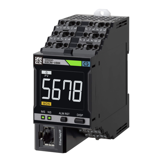
Omron K6CM series Manuals
Manuals and User Guides for Omron K6CM series. We have
5
Omron K6CM series manuals available for free PDF download: User Manual, Usage Manual, Startup Manual
Omron K6CM series User Manual (315 pages)
Motor Condition
Brand:
Omron
| Category:
Measuring Instruments
| Size: 18.42 MB
Table of Contents
Table of Contents
24
2 Device Components
41
Overview of K6CM Device
42
K6CM Device
42
Label of the K6CM Device
42
Nomenclature and Functions of the K6CM Device
43
K6CM Device
43
Transition of Numeric LCD Display
48
Status of Alarm Bar, Status Indication, and Transistor Output for each Status
49
Special CT
50
Vibration & Temperature Sensor
51
Insulation Resistance Sensor (Special ZCT (IRT))
53
Measuring and Monitoring System
55
Internal Mechanism of K6CM
56
Measuring and Monitoring by K6CM
56
Measurement System
57
Sampling of Measurement Values
57
Moving Average
58
Monitoring Delay
58
Trigger Mode
59
Maximum Value and Minimum Value of Measurement Value
65
Monitoring System
67
Types of Individual Alarms
67
What Is Comprehensive Alarm
67
Relationship between Alarm and Display/Output
68
Guide for Setting Alarm
73
Comprehensive Current Diagnosis Type (K6CM-CI2)
73
Vibration & Temperature Type (K6CM-VB)
77
How the Self-Diagnosis Function Works
79
How the Replacement Timing Notification (I.e., Running Time Function)
81
Works
81
Initialization of Setting Value
82
Introduction of the Motor Condition Monitoring Tool
83
Overview
84
What Is the Motor Condition Monitoring Tool (Software Tool) for
84
Functions and Specifications of the Software Tool
85
Installation and Uninstallation, Starting up
92
Installation
92
Uninstallation Procedures
105
IP Address Setting
106
IP Address Setting of Your PC
106
IP Address Setting of the K6CM Devices
108
Installation and Wiring
121
Dimensions
122
K6CM Device
122
Special CT
122
Vibration & Temperature Sensor
123
Insulation Resistance Sensor (Special ZCT (IRT))
124
Installation
125
Precautions at Installation
125
Installing the K6CM Device
125
Installation of the Vibration & Temperature Sensor
127
Installation of the Insulation Resistance Sensor (Special ZCT (IRT))
133
Installation of the Special CT
135
How to Connect to the Vibration & Temperature Sensor
136
When Connecting Directly to the K6CM Device
136
When Connecting by Extending the Cable
137
Recommended Ferrules and Crimp Tool
138
How to Connect to the Push-In Plus Terminal Blocks
139
The Push-In Plus Terminal Block
140
How to Use the Push-In Plus Terminal Block
140
Recommended Ferrules and Crimp Tools
142
Diagram of Terminal Description
144
I/O Wiring
145
Network Wiring
149
How to Use the Motor Condition Monitoring Tool
151
6-1 Screens
155
Monitoring Screen and Setting Screen
155
Common Menu and Toolbar List
161
Buttons on Device Setting
163
Software Tool Version Display Screen
168
Setting of K6CM Devices
169
Settings for each Monitor Type of K6CM Devices
169
Setting Parameters
173
Add a Device to an Existing Project
174
Motor (Device Group) Rename
175
Exit Project
176
Save Overwriting Project
176
Monitoring with K6Cm and Motor Condition Monitoring Tool
177
Motor Monitoring and Operation Procedure
178
Motor Monitoring Using the K6CM Devices
179
Start Measurement
179
Monitoring Type Switching
181
Monitoring Method
182
Monitoring Completed
184
Motor Monitoring Using Software Tools
185
Monitoring Procedure with Motor Condition Monitoring Tool
185
Set the Monitoring Cycle
185
Start Monitoring
186
Saving Log Files
187
Graph Vertical Axis Scale Setting
188
Graph Time Axis Movement
189
Monitoring and Setting Using the Ethernet/Ip Devices
191
Overview
192
What Is Monitoring Using Ethernet/Ip
192
Ethernet/Ip Communications Specifications
194
Monitoring Using the Tag Data Link
195
Connection Setting
195
Data to be Tag Data Link Target in the K6CM Device
199
Examples of Communications Instructions
203
Monitor Object (Class ID: 370 Hex)
203
Setting Object (Class ID: 371 Hex)
208
Identity Object (Class ID: 01 Hex)
214
TCP/IP Interface Object (Class ID: F5 Hex)
216
Examples of CIP Message Communications Instruction
218
Sample Program for the NJ/NX-Series
220
Sample Program Overview
220
Sample Program Processing Flow and Function Block Specifications
223
Sample Program Execution Procedures
229
Sample Program Code Descriptions
230
Monitoring and Setting Using the Modbus TCP Devices
235
Outline
236
Function Codes
237
Function Code List
237
03 Hex: Reading of Multiple Registers
237
06 Hex: Operation Command
239
10 Hex: Writing of Multiple Registers
240
Exception Code List
241
Register Address Lists
242
Monitoring Information
242
Setting Information
246
Product Information
252
IP Address
252
Operation Command
253
Modbus TCP Connection Timeout Time
253
A Appendices
261
A-1 Specifications
262
A-2 Measurement Values by each Monitor Type
263
A-3 K6CM Common Specifications
264
K6CM Device Individual Specifications
268
Individual Specifications of the Dedicated Sensor
270
A-6 Internal Data of K6CM Devices
274
A-7 Setting Values
275
A-8 Present Values
281
Tag Data Link Connection Setting Procedures
286
A-9-1 Using the CS/CJ-Series
286
A-9-2 Using the NJ/NX-Series
298
Expansion Error Code of the CIP Message Communications
308
A-10-1 General Status
308
A-11 Version Compatibility
311
A-11-1 Version Upgrades of the K6CM Series
311
A-11-2 Support Correspondence between the K6CM Device and Motor Condition Monitoring Tool
311
A-11-3 Motor Condition Monitoring Tool Version Compatibility
312
A-11-4 BOOTP Server Connection Error State LED Lighting Differences
312
Advertisement
Omron K6CM series User Manual (268 pages)
Motor Condition, Monitoring Device
Brand:
Omron
| Category:
Measuring Instruments
| Size: 16.17 MB
Table of Contents
Table of Contents
16
Overview and Features
22
Features
23
List of Models
25
System Configurations
26
I/O Configuration by Monitor Type
27
Insulation Resistance Sensor (ZCT (IRT))
28
Procedure
30
Using the Ethernet/Ip
31
2 Nomenclature and Functions
33
Dedicated CT
33
K6CM Device
34
Vibration & Temperature Sensor
41
Insulation Resistance Sensor (ZCT (IRT))
43
Dedicated CT
44
Measuring and Monitoring Mecha- Nism
45
Measuring and Monitoring Mechanism
45
Overview
46
Measurement System
47
Sampling of Measured Values
47
Moving Average
48
Trigger Mode
49
Maximum Value and Minimum Value of Measured Value
54
Monitoring Mechanism
56
Types of Individual Alarms
56
Comprehensive Alarm Judgment
56
Relationship between Alarm and Display/Output
57
Guide for Setting Alarm
62
Introduction of the Software Tool
67
Section 4 Introduction of the Software Tool
74
Overview
68
What Is the Motor Condition Monitoring Tool (Software Tool) for
68
Functions and Specifications of the Software Tool
69
Operating Environment of the Software Tool
74
Installation and Uninstallation, Starting up
76
Installation
76
Uninstallation Procedures
90
IP Address Setting
91
IP Address Setting of Your PC
91
IP Address Setting of the K6CM Devices
93
Installation and Wiring
105
Dimensions
106
K6CM Device
106
Vibration & Temperature Sensor
106
Insulation Resistance Sensor (ZCT (IRT))
107
Dedicated CT
108
Installation
109
Installing the K6CM Device
109
Precautions at Installation
109
Installation of the Vibration & Temperature Sensor
111
Installation of the Insulation Resistance Sensor (ZCT (IRT)
114
Installation of the Dedicated CT
117
How to Connect to the Push-In Plus Terminal Blocks
118
How to Use the Push-In Plus Terminal Block
119
The Push-In Plus Terminal Block
119
Recommended Ferrules and Crimp Tools
121
Diagram of Terminal Description
123
I/O Wiring
124
Ethernet/Ip Wiring
128
How to Use the Software Tool
131
Section 5 Installation and Wiring
132
Section 6 How to Use the Software Tool
132
Screens
132
6-1 Screens
135
Monitoring Screen and Setting Screen
135
Common Menu and Toolbar List
146
Buttons on Device Setting
148
Setting of K6CM Devices
152
Settings for each Monitor Type of K6CM Devices
152
Setting Parameters
155
Add a Device to an Existing Project
156
Motor (Device Group) Rename
157
Save Overwriting Project
157
Exit Project
158
Motor Monitoring with the K6Cm Devices and the Software Tool
159
Motor Monitoring and Operation Procedure
160
Motor Monitoring Using the K6CM Devices
161
Start Measurement
161
Monitoring Type Switching
163
Monitoring Method
164
Measuring and Monitoring Completed
166
Motor Monitoring Using Software Tools
167
Monitoring Procedure with Motor Condition Monitoring Tool
167
Set the Monitoring Cycle
167
Start Monitoring
168
Saving Log Files
169
Monitoring and Setting Using the Ethernet/Ip Devices
171
Overview
172
What Is Monitoring Using Ethernet/Ip
172
Ethernet/Ip Communications Specifications
174
Monitoring Using the Tag Data Link
175
Connection Setting
175
Data to be Tag Data Link Target in the K6CM Device
179
Monitoring and Setting Using the CIP Message Communications and Examples of Communications Instructions
182
Monitor Object (Class ID: 370 Hex)
183
Setting Object (Class ID: 371 Hex)
188
Identity Object (Class ID: 01 Hex)
193
TCP/IP Interface Object (Class ID: F5 Hex)
195
Examples of CIP Message Communications Instruction
197
Sample Program for the NJ/NX-Series
199
Sample Program Overwiew
199
Sample Program Processing Flow and Function Block Specifications
201
Sample Program Execution Procedures
206
Sample Program Code Descriptions
207
Trouble Shooting
211
A Appendices
217
A-1 Specifications
218
Measured Values by each Monitor Type
219
A-3 K6CM Common Specifications
221
K6CM Device Individual Specifications
224
Individual Specifications of the Dedicated Sensor
226
A-6 Internal Data of K6CM Devices
230
A-7 Setting Values
231
A-8 Present Values
235
Tag Data Link Connection Setting Procedures
240
A-9-1 Using the CS/CJ-Series
240
Using the CS/CJ-Series
240
Using the NJ/NX-Series
252
Expansion Error Code of the CIP Message Communications
262
A-10-1 General Status
262
A-10-2 Additional Status When General Status Is 01 Hex
263
Omron K6CM series User Manual (206 pages)
Motor Condition Monitoring Device
Brand:
Omron
| Category:
Measuring Instruments
| Size: 19.76 MB
Table of Contents
Preface
3
Terms and Conditions Agreement
4
Application Considerations
5
Disclaimers
5
Safety Precautions
6
Definition of Precautionary Information
6
Symbols
6
Precautions for Safe Use
9
Precautions for Correct Use
12
Revision History
14
Sections in this Manual
15
Table of Contents
16
Contents
17
Overview
21
Overview and Features
22
What Is the K6CM Motor Condition Monitoring Devices for
22
Features
23
List of Models
24
Models of K6CM Device
24
Lists of Sensor Models Used
25
System Configurations
26
Overall System Configuration
26
I/O Configuration for each Monitor Type of K6CM Devices
27
Specifications
29
Measurement Value or Measurement Range and Alarm Monitoring for each Monitor Type
29
K6CM Common Specifications
30
K6CM Device Individual Specifications
33
Individual Specifications of the Sensor Used
35
Procedure
38
Nomenclature and Functions
43
2-1 Nomenclature and Functions
44
K6CM Device
44
Nomenclature and Functions
44
Vibration & Temperature Sensor
49
Insulation Resistance Sensor (ZCT (IRT))
51
Dedicated CT
51
Mechanism of Measuring and Monitoring of the K6CM Devices
53
Section 3 Mechanism of Measuring and Monitoring of the K6CM
54
Mechanism of Measurement and Monitoring (Alarm) of the K6CM
54
Overview
54
Types of Individual Alarms
55
Comprehensive Alarm Judgment
55
Relationship between Comprehensive Alarm and Alarm Bar/Transistor Output
56
K6CM Devices
59
Guide for Setting Alarm Threshold for the Vibration & Temperature Type (K6CM-VBM)
62
Guideline for Setting the Alarm Threshold Value of the Comprehensive Current Diagnosis Type (K6CM-CIM)
64
Measuring and Monitoring Execution Conditions
66
Trigger Mode
66
Detailed Information on Trigger Mode and Behavior by Status
69
Maximum and Minimum Measurement Values
71
Overview
71
Update and Storage of Maximum and Minimum Measurement Values
71
Installation and Wiring
75
Section 4 Installation and Wiring
76
Dimensions
76
K6CM Device
76
Vibration & Temperature Sensor
76
Insulation Resistance Sensor (ZCT (IRT))
77
CT (Current Transformer) for Comprehensive Current Diagnosis Type
78
Install the K6CM Devices
79
Precautions at Installation
79
Installing the K6CM Device
79
Installation of Pre-Amplifier
81
Installation of Vibration Sensor Head
81
Installation and Connection of Insulation Resistance Sensor ZCT (IRT)
84
Installation and Connection of Dedicated CT
86
How to Connect to the Push-In Plus Terminal Blocks
88
Type of Terminal Block
88
The Push-In Plus Terminal Block
89
Nomenclature of the Push-In Plus Terminal Block and Connections
89
Removing Wires from the Push-In Plus Terminal Block
91
Recommended Ferrules and Crimp Tools
91
I/O Wiring
93
Power Supply Input Wiring
96
External Trigger Input Wiring (Excluding the K6CM-ISM)
97
Transistor Outputs Wiring
98
Ethernet/Ip Wiring
100
Setting with the Motor Condition Monitoring Tool
101
Section 5 Setting with the Motor Condition Monitoring Tool
102
Overview
102
What Is the Motor Condition Monitoring Tool for
102
Functions and Specifications of the Motor Condition Monitoring Tool
103
Operating Environment of the Motor Condition Monitoring Tool
105
Installation and Uninstallation, Starting up
106
Installing .NET Framework 3.5 SP1
106
Installation Procedures
113
Uninstallation Procedures
118
Motor Condition Monitoring Tool IP Address Settings on the Computer Side before Starting
119
How to Activate the Motor Condition Monitoring Tool
121
Screen Transitions and Descriptions of each Screen
122
Screen Transition
122
Relationship between the Project to be Created and the Screen
123
Descriptions of each Screen
124
Common Menu and Toolbar List
129
Tool Button and Software Reset Button on Device Setting Screen
131
Initial Setting of K6CM Devices
135
Overview
135
Motor Condition Monitoring Tool Connection Method
135
Procedure for Setting IP Address (When Necessary, Further Parameters)
137
Set Parameters
146
Add a Device to an Existing Project
147
Change the Name of the Motor (Device Group)
148
Overwrite and Save the Project
148
Close the Project
148
Internal Data List of the K6CM Devices
151
Internal Data of K6CM Devices
152
Settings
153
Alarm Setting Values (Threshold Value)
153
Other Setting Values
154
Present Value
157
Measurement Value
157
Values Other than Measurement Values
159
Alarm Results
160
Motor Monitoring and Operation with the K6CM Devices and the Motor Condition Monitoring Tool
163
Motor Monitoring and Operation Procedure
164
Start Measurement with the K6CM Devices
165
Start Measurement
165
Changing the Monitoring Category, and Checking the Measured Values
167
Measuring and Monitoring Completed
167
Monitor with the Motor Condition Monitoring Tool
168
Monitoring Procedure with Motor Condition Monitoring Tool
168
Set the Monitoring Cycle
168
Start Monitoring
169
Saving Log Files
170
Monitoring with the K6CM Devices
171
How to Monitor with the K6CM Devices
171
Section 8 Monitoring and Setting with the Ethernet/Ip
174
Monitoring and Setting with the Ethernet/Ip
174
Overview
174
What Is Monitoring Using Ethernet/Ip
174
Ethernet/Ip Communications Specifications
178
List of Monitoring Contents with Tag Data Link
179
Connection Setting
179
Data to be Tag Data Link Target in the K6CM Device
180
Monitoring and Setting Using the CIP Message Communications and Examples of Communications Instructions
183
Services Supported by Objects in K6CM
183
K6CM Monitor Object (Class ID: 370 Hex)
183
K6CM Setting Object (Class ID: 371 Hex)
187
Identity Object (Class ID: 01 Hex)
191
TCP/IP Interface Object (Class ID: F5 Hex)
193
Examples of CIP Message Communications Instruction
195
Trouble Shooting
197
Section 9 Trouble Shooting
198
K6CM Devices
198
Using the Motor Condition Monitoring Tool
199
Using the Ethernet/Ip
200
Index
201
Advertisement
Omron K6CM series Usage Manual (64 pages)
Condition Monitoring Configuration Tool
Brand:
Omron
| Category:
Measuring Instruments
| Size: 6.94 MB
Table of Contents
Contents
3
Important
5
Software License Agreement
5
Safety Precautions
8
Definition of Precautionary Information
8
Symbols
8
Precautions for Safe Use
10
Precautions for Correct Use
11
Revision History
12
Related Manuals
12
Manual Structure
12
Icons
12
Table of Contents
3
Introduction
13
Overview
13
Features
13
Screen Transitions of the Tool and Section Structure of this Guide
14
Screen Transition of the Tool
14
Section Structure of this Guide
15
1 Common Settings
16
Startup Screen/ Creating a Project
17
Add Monitoring Device (Home Screen (1))
18
Communication Settings (Home Screen (2))
19
Machine Abnormal Condition Registration/Alarm Thresholds Setting (Home Screen (3))
22
Logging/Digital Maintenance Log (Home Screen (4))
25
2 Basic Settings
27
K6CM Basic Settings
28
K6PM Basic Settings
30
K7GE Basic Settings
32
K7TM Basic Settings
34
K7DD Basic Settings
36
3 Features Analysis
37
K7DD Features Analysis
38
4 Alarm Settings
42
K6CM/K7GE/K7TM Alarm Settings
43
K6PM Alarm Settings
45
K7DD Alarm Settings
47
5 Logging
49
K6CM Logging
51
K6PM Logging
52
K7GE Logging
53
K7TM Logging
54
K7DD Logging
55
6 Digital Maintenance Log
56
7 Troubleshooting
58
Appendices
59
Operating Environment
59
Important Note on Compatibility with Existing Tools
59
Index
60
Omron K6CM series Startup Manual (36 pages)
Motor Condition Monitoring Device
Brand:
Omron
| Category:
Measuring Instruments
| Size: 4.01 MB
Table of Contents
Installation Procedures
9
Installation
24
Screw Mounting
24
Connection Diagram
25
Sensor Connection
26
Terms and Conditions Agreement
35
Programmable Products
35
Advertisement
Related Products
Omron K6CM-VBMA-EIP
Omron K6CM-CIMA-EIP
Omron K6CM-CIMD-EIP
Omron K6CM-VBMD-EIP
Omron K6CM-ISMA-EIP
Omron K6CM-ISMD-EIP
Omron K6CM-ISM
Omron K6CM-CIM
Omron K6CM-VBM
Omron K6CM-CI2M
Omron Categories
Blood Pressure Monitor
Controller
Accessories
Switch
Inverter
More Omron Manuals
Login
Sign In
OR
Sign in with Facebook
Sign in with Google
Upload manual
Upload from disk
Upload from URL