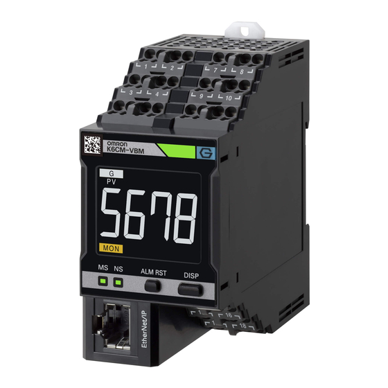
Omron K6CM Usage Manual

Omron K6CM Usage Manual

Condition monitoring configuration tool
Hide thumbs Also See for K6CM:

Advertisement

Quick Links

Condition Monitoring Configuration Tool
Usage Guide
1
Common Settings
2
Basic Settings
3
Features Analysis
4
Alarm Settings
5
Logging
6
Digital Maintenance
Log
7
Troubleshooting
A
Appendix
I
Index
N240-E1-01

Advertisement

Table of Contents
loading

Summary of Contents for Omron K6CM

  • Page 1 Common Settings Condition Monitoring Configuration Tool Basic Settings Features Analysis Usage Guide Alarm Settings Logging Digital Maintenance Troubleshooting Appendix Index N240-E1-01...
  • Page 2 No patent liability is assumed with respect to the use of the information contained herein. Moreover, because OMRON is constantly striving to improve its high-quality products, the information contained in this manual is subject to change without notice. Every precaution has been taken in the preparation of this manual. Neverthe- less, OMRON assumes no responsibility for errors or omissions.
  • Page 3: Table Of Contents

    Machine Abnormal Condition Registration/Alarm Thresholds Setting (Home Screen (3)) ..............................20 Logging/Digital Maintenance Log (Home Screen (4)) ............23 2. Basic Settings K6CM Basic Settings......................26 K6PM Basic Settings......................28 K7GE Basic Settings ......................30 K7TM Basic Settings ......................32...
  • Page 4 K7DD Basic Settings ......................34 3. Features Analysis K7DD Features Analysis ......................36 4. Alarm Settings K6CM/K7GE/K7TM Alarm Settings..................41 K6PM Alarm Settings ......................43 K7DD Alarm Settings......................45 5. Logging K6CM Logging ........................49 K6PM Logging ........................50 K7GE Logging......................... 51 K7TM Logging.........................
  • Page 5: Important

    Software and have to immediately stop installing or downloading Software. Software License Agreement This is a binding agreement between User and OMRON Corporation, a corporation organized and existing under the laws of Japan with its place of business at Shiokoji Horikawa, Shimogyo-ku, Kyoto, Japan (“OMRON”) on the terms and conditions to use Software.
  • Page 6 Title and ownership of all Intellectual Property Rights in Software will at all times remain with OMRON or the third party who has licensed Software to OMRON, as the case may be. The rights granted to User by OMRON under such Intellectual Property Rights are only for the purposes set forth expressly in this Agreement.
  • Page 7 OMRON Indemnitees as a result of (a) a breach of this Agreement by User, (b) User’s violation of applicable law, or (c) the negligence or other wrongful conduct of User.
  • Page 8: Safety Precautions

    Safety Precautions Definition of Precautionary Information The following notation is used in this Guide to provide precautions required to ensure safe usage of the product. The safety precautions that are provided are extremely important to safety. Always read and follow the information provided in all safety precautions.
  • Page 9 Data input and output protection Validate backups and ranges to cope with unintentional modification of input/output data to a con- trol/monitor system and equipment. • Checking the scope of data • Checking validity of backups and preparing data for restore in case of data tampering and abnor- malities •...
  • Page 10: Precautions For Safe Use

    Precautions for Safe Use • In addition to this Guide, also refer to the Instruction Manual and User’s Manual for each Condition Monitoring Device. • Ensure that a destination Condition Monitoring Device is not in a monitoring state before you transfer parameters to it.
  • Page 11: Precautions For Correct Use

    Precautions for Correct Use • Use the Condition Monitoring Configuration Tool only on the specified operating system. The Condition Monitoring Configuration Tool may malfunction on other operating systems. • Do not use the Condition Monitoring Configuration Tool near electrical noise sources such as motors and power lines.
  • Page 12: Revision History

    The following table shows related manuals. Use these manuals for reference. Manual name Cat. No. Condition Monitoring Configuration Tool Usage Guide (this manual) N240 K6CM Motor Condition Monitoring Device User's Manual N219 K6PM-TH Thermal Condition Monitoring Device User's Manual H231 K7GE-MG Insulation Resistance Monitoring Device User's Manual...
  • Page 13: Introduction

    Condition Monitoring Configuration Tool (hereafter referred to as the ‘Tool’ when applicable) is software that supports the configuration of the following devices. Product name Model Motor Condition Monitoring Device K6CM Temperature Condition Monitoring Device K6PM Insulation resistance Monitoring Device K7GE...
  • Page 14: Screen Transitions Of The Tool And Section Structure Of This Guide

    Introduction Screen Transitions of The Tool and Section Structure of This Guide Screen Transition of The Tool This Tool allows you to configure settings in order from (1) Add Moni- Start up Screen toring Device through (6) Digital Maintenance Log via the Home Screen.
  • Page 15: Section Structure Of This Guide

    (Warning/Critical) Warning (Warning/Critical) Settings Section 4-3 Section 4-1 Section 4-2 Section 4-1 Common Part Section 5 (5) Logging K6CM Logging K6PM Logging K7GE Logging K7TM Logging K7DD Logging Section 5-1 Section 5-2 Section 5-3 Section 5-4 Section 5-5 Setting Completed/Operation (6) Digital...
  • Page 16: Common Settings

    1 Common Settings 1. Common Settings In this section, explanations for the fol- Parts described in Section 1 Common Settings. lowing screen transitions are provided. The content primarily includes infor- mation that cannot be inferred from Start up Screen the Tool screen. •...
  • Page 17: Startup Screen/ Creating A Project

    Create Project Dialog Box If you check the box for 'Use default location,' the project file will be saved to the following location. C:\OMRON\Application\Condition Monitoring Configuration Tool How to Save the Project Select Save Project from the File Menu at the top left of the screen to save the project.
  • Page 18: Add Monitoring Device (Home Screen (1))

    Add Machine and Monitoring Device Dialog Box • Monitoring Device from the Pull-down Menu: K6CM-CI2M (Motor Condition Monitoring Device Comprehensive Current Diagnosis Type) *Default K6CM-ISM (Motor Condition Monitoring Device Insulation Resistance Type) K6CM-VBM (Motor Condition Monitoring Device Vibration & Temperature Type)
  • Page 19: Communication Settings (Home Screen (2))

    You need to set the IP address of your computer to the same network as the target communication IP address, to use the Tool. Refer to the 4-3 IP Address Setting in the K6CM User's Manual (N219) as a setting example.
  • Page 20 Modbus command of your choice. For information on the send commands, refer to the manuals of the condition monitoring devices. You can set the IP Address, Subnet Mask, and Default Gateway for K6CM and K6PM. Execute the Communication Test again after setting them.
  • Page 21 (Warning/Critical) Warning (Warning/Critical) Section 4-3 Settings Section 4-1 Section 4-2 Section 4-1 Common Part Section 5 (5) Logging K6CM Logging K6PM Logging K7GE Logging K7TM Logging K7DD Logging Section 5-1 Section 5-2 Section 5-3 Section 5-4 Section 5-5 Setting Completed/Operation (6) Digital...
  • Page 22: Machine Abnormal Condition Registration/Alarm Thresholds Setting (Home Screen (3))

    You can register the parts name and abnormal name. Example: K6PM: Contactor/Abnormal tem- perature inside the panel K6CM: Belt Conveyor/Degradation Home Screen (3) level 1  K7DD Click the + Button to the right of Machine Abnormal Condition on the Home Screen (3).
  • Page 23 1 Common Settings Click Features Analysis for Alarm Threshold Calculation to go to the next screen. Refer to Section 3 Features Analy- sis on page 35 for details. Home Screen (3) Click Data Registration for Digital Maintenance Log to go to the next screen.
  • Page 24 1 Common Settings How to Set Alarm Thresholds  K6CM/K6PM/K7GE/K7TM Click Alarm Settings on the Home Screen (3). Home Screen (3) Alarm Settings parameter is described for each condition monitoring device. For details on Alarm Settings parameter, refer to the respective page numbers for each model listed under (4) Alarm Settings in the figure below.
  • Page 25: Logging/Digital Maintenance Log (Home Screen (4))

    1 Common Settings Logging/Digital Maintenance Log (Home Screen (4)) After setting the parameter of Alarm Set- tings, the Home Screen (4) is displayed. A check mark appears to the left of Alarm Settings. Home Screen (4) You can set the following items on the Home Screen (4): Settings Item Description Logging...
  • Page 26 (Warning/Critical) Warning (Warning/Critical) Section 4-3 Settings Section 4-1 Section 4-2 Section 4-1 Common Part Section 5 (5) Logging K6CM Logging K6PM Logging K7GE Logging K7TM Logging K7DD Logging Section 5-1 Section 5-2 Section 5-3 Section 5-4 Section 5-5 Setting Completed/Operation (6) Digital...
  • Page 27: Basic Settings

    Parts described in Section 2 Basic Settings. Basic Settings are provided. The con- tent primarily includes information that cannot be inferred from the Tool Start up Screen screen. • K6CM (three models) Home Screen (1) • K6PM AddMachineAndMonitoringDevice 1. Add • K7GE...
  • Page 28: K6Cm Basic Settings

    Settings (Home Screen (2)) for information on Communication Settings. K6CM Initial Settings This is the Initial Settings Screen in the Basic Settings. The setting parameters for three K6CM mod- els are as follows: Initial Settings Motor Condition Monitoring Device...
  • Page 29 If noise is induced when the equipment starts up or when operation is unstable, set the measurement timing while taking into consideration the time required for noise removal over a specified period. Refer to Section 3 Measuring and monitoring System of the K6CM User's Manual (N224) for details. This is the Trigger Settings Screen in the Basic Settings.
  • Page 30: K6Pm Basic Settings

    2 Basic Settings K6PM Basic Settings The Initial Settings and Infrared Thermal Sensor Settings in the Basic Settings are described below. Refer to 1-3 Communication Settings (Home Screen (2)) for information on Communication Settings. K6PM does not have Trigger Settings. K6PM Initial Settings This is the Initial Settings Screen in the Basic Settings.
  • Page 31 2 Basic Settings Left: Thermal image settings The thermal image of the specified sensor number is displayed. The fol- lowing settings can be made. • Color scale settings according to the temperature • Rotation of thermal image • Select the Overlay the measure- ment range check box, displaying the loaded photo overlaid on the thermal image in the Measuring...
  • Page 32: K7Ge Basic Settings

    2 Basic Settings K7GE Basic Settings The Initial Settings and Trigger Settings in the Basic Settings are described below. Refer to 1-3 Com- munication Settings (Home Screen (2)) for information on Communication Settings. K7GE Initial Settings This is the Initial Settings Screen in the Basic Settings.
  • Page 33 2 Basic Settings K7GE Trigger Settings K7GE automatically measures in synchronization with a trigger signal. Set the necessary parameters for automatic measurement. This is the Trigger Settings Screen in the Basic Settings. Setting parameters are as follows: Trigger Settings Insulation Resistance Monitoring Device Setting Parameter K7GE-MG Trigger Signal Reverse, Motor Stop Waiting Time, Time to Wait...
  • Page 34: K7Tm Basic Settings

    2 Basic Settings K7TM Basic Settings The Initial Settings and Reference Resistance Value Registration in the Basic Settings are described below. Refer to 1-3 Communication Settings (Home Screen (2)) for information on Communication Settings. K7TM does not have Trigger Settings. K7TM Initial Settings This is the Initial Settings Screen in the Basic Settings.
  • Page 35 2 Basic Settings K7TM Reference Resistance Value Registration This is the Reference Resistance Value Registration Screen in Basic Settings. You can register a resistance value that serves as a reference for the condition monitoring device to detect heater degradation. Run the heater and register the reference resistance value under stable temperature conditions. When replacing the heater with a new one, it is recommended to perform this function for the corresponding heater channel.
  • Page 36: K7Dd Basic Settings

    2 Basic Settings K7DD Basic Settings The Initial Settings and Trigger Settings in the Basic Settings are described below. Refer to 1-3 Com- munication Settings (Home Screen (2)) for information on Communication Settings. K7DD Initial Settings This is the Initial Settings Screen in the Basic Settings.
  • Page 37: Features Analysis

    3 Features Analysis 3. Features Analysis This section describes the Feature Parts described in Section 3 Features Analysis. Analysis Screen for K7DD only. The content primarily includes information that cannot be inferred from the Tool Start up Screen screen. Home Screen (1) AddMachineAndMonitoringDevice 1.
  • Page 38: K7Dd Features Analysis

    3 Features Analysis K7DD Features Analysis The feature analysis function is only available for K7DD. This function can analyze 400 types of fea- tures from normal and abnormal data and can calculate the feature with the largest rate of change from abnormal data.
  • Page 39 3 Features Analysis *1. Use the Get from File Button when accessing to use previously acquired data. Data file names are created according to the following rules: Normal data: Normal_yyyy-MMdd-HHmmss.csv Abnormal data: Abnormal_yyyy-MMdd-HHmmss.csv  Registration of Abnormal Data Next, start registering abnormal data. The following options are available for abnormal data: •...
  • Page 40 3 Features Analysis K7DD Features Selection The optimal features for monitoring are automatically displayed based on the normal and abnormal data registered on the Data Registration Screen. Select the checkboxes for the features with a largest change rate displayed in the Score. This is the Features Selection Screen.
  • Page 41 3 Features Analysis K7DD Threshold Calculation Set the alarm thresholds for the selected feature for monitoring on the Features Selection Screen. You can set them depending on the timing of the alarm output selected from early, middle, and late. At this point, the alarm thresholds have not yet been set on the K7DD. Refer to the Alarm Settings in Section 4 for details.
  • Page 42: Alarm Settings

    Tool Start up Screen screen. Although the setting screens for each Home Screen (1) condition monitoring device are differ- AddMachineAndMonitoringDevice 1. Add ent, the alarm settings for K6CM, Monitoring Device K7GE, and K7TM are described Home BasicSettings Screen (2) together.
  • Page 43: K6Cm/K7Ge/K7Tm Alarm Settings

    4 Alarm Settings K6CM/K7GE/K7TM Alarm Settings The alarm settings for the following models are described here. • K6CM-series (K6CM-CI2, K6CM-IS and K6CM-VB) • K7GE • K7TM Alarm Settings for K6CM/K7GE/K7TM Set alarm values to detect abnormalities. Make sure the settings on the Tool match those of the condition monitoring device.
  • Page 44 4 Alarm Settings Acceleration Alarm, Speed Alarm Threshold Setting Guide (K6CM-VB Vibration & temperature type only) The Acceleration alarm, speed alarm threshold setting guide is displayed on the right side of the Alarm Settings Screen for K6CM-VB. It allows for the following automatic settings: •...
  • Page 45: K6Pm Alarm Settings

    4 Alarm Settings K6PM Alarm Settings The K6PM alarm settings are described below. Alarm Settings for K6PM Set the alarm values for each sensor that detect abnormalities, and write them to K6PM. This is Alarm Settings Screen. This screen is updated every 5 seconds. Click Alarm Settings corresponding to the sensor number.
  • Page 46 4 Alarm Settings Set the thresholds You can use the Automatic threshold calculation function. ■ How to use Automatic threshold calculation (1) After resetting the maximum temperature, con- duct monitoring for several days. Measuring other objects (such as human bodies) than the intended target or misalignment of the monitor- ing position may affect the automatic threshold calculation.
  • Page 47: K7Dd Alarm Settings

    4 Alarm Settings K7DD Alarm Settings The K7DD alarm settings are described below. Alarm Settings for K7DD The K7DD alarm settings is a function that integrates the feature value and alarm threshold for each abnormality calculated by feature analysis (see 3-1 K7DD Features Analysis on page 36) to set the alarm.
  • Page 48 4 Alarm Settings Select the features to merge the thresholds. Basically, select all items. K7DD Alarm Settings Click the Marge Alarm Thresholds Button. The alarm values of the features set for each abnormality are merged based on the threshold of the side more likely to trigger an alarm.
  • Page 49: Logging

    5 Logging 5. Logging In this section, explanations for the Parts described in Section 5 Logging. Logging Screen are provided. The content primarily includes information that cannot be inferred from the Tool Start up Screen screen. The logging function is used for a tem- Home Screen (1) porary check to confirm whether the AddMachineAndMonitoringDevice...
  • Page 50 5 Logging  Trend Monitor The waveforms during logging are displayed in real-time. The displayed target data cannot be changed throughout the logging session. When alarm values are set, warning levels are indicated by yellow lines, and critical levels are indicated by red lines. ...
  • Page 51: K6Cm Logging

    K6CM Logging The Logging Screen for K6CM is described below. K6CM Logging Screen The content of the Logging Screen for the K6CM series (K6CM-CI2, K6CM-IS, or K6CM-VB) is provided below. For illustrative purposes, the following screen shows the logging of K6CM-CI2.
  • Page 52: K6Pm Logging

    5 Logging K6PM Logging The Logging Screen for K6PM is described below. K6PM Logging Screen Area Item Description Logging Interval 1 minute, 10 minutes, 30 minutes, 1 hour, or 6 hours Logging Target Data Displays sensors with completed basic settings. The following items can be selected for segments (00-15) and sensors (1-31).
  • Page 53: K7Ge Logging

    5 Logging K7GE Logging The Logging Screen for K7GE is described below. K7GE Logging Screen Area Item Description Logging Interval 1 minute, 10 minutes, 30 minutes, 1 hour, or 6 hours Logging Target Data CH1 to 8 measurement values Refer to the K7GE-MG User's Manual (N224) for details on the status. Icon Description Critical...
  • Page 54: K7Tm Logging

    5 Logging K7TM Logging The Logging Screen for K7TM is described below. K7TM Logging Screen Area Item Description Logging Interval 5 seconds, 1 minute, 10 minutes, 30 minutes, or 1 hour Logging Target Data Reference resistance value change rate, voltage value, current value, power Refer to the K7TM User's Manual (N227) for details on the status.
  • Page 55: K7Dd Logging

    5 Logging K7DD Logging The Logging Screen for K7DD is described below. K7DD Logging Screen Area Item Description Logging Interval None*1, 5 seconds, 10 seconds, 30 seconds, or 1 minute Logging Target Data Refer to 5-2-1 All Feature Measurement of the K7DD User's Manual (N233). *1.
  • Page 56: Digital Maintenance Log

    6 Digital Maintenance Log 6. Digital Maintenance Log In this section, explanations for the Parts described in Section 6 Digital Maintenance Log. Digital Maintenance Log are provided. The content primarily includes infor- mation that cannot be inferred from Start up Screen the Tool screen.
  • Page 57 6 Digital Maintenance Log K7DD Digital Maintenance Log The content of the Digital Maintenance Log Screen for K7DD is provided below. The screen shown below can be displayed by clicking the Digital Maintenance Log Button on the Home Screen (4). Area Item Description...
  • Page 58: Troubleshooting

    7 Troubleshooting 7. Troubleshooting Status Cause Correction Reference Unable to The IP address of the PC or Check the IP address of the PC or Manuals for each condition monitoring device communicate. condition monitoring device condition monitoring device (com- (communication converter) is munication converter).
  • Page 59: Appendices

    K6CM Exclusive Tools • Auto-connect via AutoIP Motor Condition Monitoring Tool • Connecting to EIP CPU version 1.0 or 1.1 of K6CM • Monitoring screen for all connected K6CM • Copy of setting values (Input/output of parameter data file with k6pa extension) •...
  • Page 60: Index

    Index Index Alarm Settings Important note on compatibility with existing tools ..57 K6CM ................. 41 Infrared Thermal Sensor Settings K6PM ................. 43 K6PM ................. 28 K7DD ................. 45 Initial Settings K7GE ................. 41 K6CM ................. 26 K7TM ................. 41 K6PM .................
  • Page 61 Index Setting parameter K6CM-CI2 ............26, 27, 41 K6CM-IS ............26, 27, 41 K6CM-VB ............26, 27, 41 K6PM-TH ..............28 K7DD-PQ ..............34 K7GE-MG ............30, 31, 41 K7TM-A2 ..............32, 33 K7TM-A2M ..............41 Thermal image settings K6PM .................29 Thresholds calculated based on the selected alarm timing K7DD ................39...
  • Page 62 Index Condition Monitoring Configuration Tool Usage Guide (N240)
  • Page 64 Hoffman Estates, IL 60169 U.S.A. Tel: (31) 2356-81-300 Fax: (31) 2356-81-388 Tel: (1) 847-843-7900 Fax: (1) 847-843-7787 ©OMRON Corporation 2018-2024 All Rights Reserved. OMRON ASIA PACIFIC PTE. LTD. OMRON (CHINA) CO., LTD. In the interest of product improvement, 438B Alexandra Road, #08-01/02 Alexandra Room 2211, Bank of China Tower, specifications are subject to change without notice.

This manual is also suitable for:

K6pmK7geK7tmK7dd

Table of Contents