Omron K6CM Startup Manual
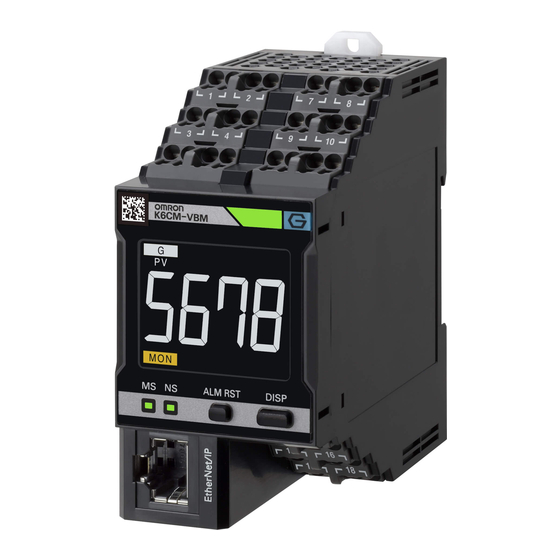
Motor condition monitoring device
Hide thumbs
Also See for K6CM:
- User manual (315 pages) ,
- Usage manual (64 pages) ,
- User manual (206 pages)
Advertisement
Quick Links
Motor Condition
Monitoring Device
K6CM
Startup Guide
0
Step
Selection of sensor to use
1
Step
Confirmation of details
Preparation of necessary
2
Step
items
Installation of Motor
3
Step
condition monitoring Tool
K6CM configuration in the Motor
4
Step
condition monitoring Tool
5
Step
Installation
6
Step
Connection
7
Step
Monitoring
8
Step
Pre-verification
Advertisement

Related Manuals for Omron K6CM


Summary of Contents for Omron K6CM
- Page 1 Startup Guide Step Selection of sensor to use Step Confirmation of details Preparation of necessary Step items Installation of Motor Step condition monitoring Tool K6CM configuration in the Motor Step condition monitoring Tool Step Installation Step Connection Step Monitoring Step Pre-verification...
- Page 2 This uses a single sensor per motor that can detect vibration and temperature at the same time. One type of sensor can be used. (Sensor model: K6CM-VBS1) Insulation resistance This uses one ZCT per motor to detect leakage current. One type of ZCT can be used. (ZCT model: K6CM-ISZBI52)
- Page 3 Startup Guide Step Selection of sensor to use Step Confirmation of details Preparation of necessary Step items Motor condition monitoring Step Tool installation K6CM configuration in the Motor Step condition monitoring Tool Step Installation Connection Step □ Push-in Plus Terminal Block wiring Step Monitoring * Prepare a PC that meets the following conditions.
- Page 4 * In Windows version 8.1 or later OS version, the "Microsoft .NET Framework 3.5" required for installing the above mentioned attached software is not installed in advance. Therefore, if you are using a PC with the above OS ver- sion and cannot connect to the network, you cannot acquire the above. NET and you cannot install the software included with the Motor condition monitoring Tool. Outline of this procedure (Install Motor condition monitoring Tool after [3]) Network K6CM Win 8.1/10 [1] Obtaining OS media creation [3] . NET Framework 3.5 Offline installation [2] Preparation of OS media USB memory, HDD...
- Page 5 2) Enter “winver”and click [OK].Button. 3) The Windows version is displayed, so confirm. [2] OS media creation Run the downloaded OS media creation tool. Be sure to select "Create installation media of another PC" for the option after agreeing to the license terms In the selection screen of language, architecture, and edition, uncheck the check box at the bottom and select the same one as the PC you want to install the Motor condition monitoring Tool.
- Page 6 Select the media type to use. When selecting "USB flash drive", be sure to prepare an empty recording medium (USB memory of 8 GB or more, HDD or DVD) without data. At this point, connect the USB memory to your PC and select "Next" on the installation screen. Confirm that the USB memory is normally recognized by the PC and displayed as a removable drive as below and proceed with creating OS media.
- Page 7 Since the Explorer screen starts, click the drive icon displayed on the left side of the screen that started up.If the OS media is recognized correctly, the drive containing the following data will be displayed. Execute the command prompt (shell script) with administrator privileges after confirming that the OS media was recognized correctly. Hold down the Windows key while pressing the X key, the following screen will be displayed, so select Windows PowerShell (Administrator). After that, confirm that the following command prompt screen is displayed.
- Page 8 Enter the following command and press Enter to execute. In the command, "D:" is the drive to which the OS media checked earlier was assigned. Depending on the user environment used. As you can see, be sure to modify the command according to the drive information you have confirmed. Command : Dism /Online /Enable-Feature /FeatureName:NetFX3 /All/Source:D:¥Sources¥SxS /LimitAccess * Enter the command on one line without line break. Insert a space between Dism and the set of words (/ ***) that compose the command. Wait for a while until the completion screen as shown below. If this screen can be confirmed, the installation of .NET Framework 3.5 will be completed, continue installing the Motor condition monitoring Tool. (2) Select "Programs" from the Control Panel. (3) Select "Turn Windows features on or off".
-
Page 9: Installation Procedures
(4) Check the check box of "Microsoft .NET Framework 3.5.1" and click "OK". 2 Installation Procedures This section shows the procedure for installing a new Motor condition monitoring Tool. 使用上の注意 使用上の注意 Precautions for Correct Use "User account control" may be displayed depending on PC settings during installation procedure. In that case, click "yes" if there is no problem. (1) Insert the attached CD in the PC and select "setup.exe" from the autoplay screen. If automatic playback was not done, double-click the "setup.exe" file under the CD drive. - Page 10 CAUTION If the following message is displayed, a newer version of the software tool than the launched installer has already been installed on your PC. Therefore, installation is unnecessary. CAUTION If the following message is displayed, a software tool of the same version as the launched installer has already been installed in your PC. [Modify] is used to change the function to be installed. Do not use it now for future expansion. [Repair] is used to reinstall the software tool. [Remove] is used to uninstall the software tool. CAUTION If the following message is displayed, a older version of the software tool than the launched installer is installed on your PC. To update the software tool, click [Next] Button. Start updating after clicking. When the update is completed, a completion message is displayed.
- Page 11 The [User Information] Dialog Box appears. (5) Click the "Install" Button. Installation of the Motor condition monitoring Tool starts. (6) Install the Communications Middleware. Select the language to display in the installation. If an old version of the Communications Middlware is already installed, select whether to update Communications Middlware. If a new version of the Communications Middlware is already installed, go to step (15). (7) While the installation wizard is running, the [Windows Security] Dialog Box will be displayed. Click the [Install] Button. "OMRON Corporation Modems" is installed and the following [Windows Security] Dialog Box will be displayed. (8) Click the [Install] Button. "OMRON Corporation Ports (COM & LPT)" is installed.
- Page 12 (9) Since a dialog box prompting you to install WinPcap which is a component of Communications Middleware is displayed, click the [OK] Button. If WinPcap is already installed, go to step (15). (10) Click the [Next] Button. (11) Click the [I Agree] Button. The Installation options Dialog Box appears. (12) Check "Automatically start the WinPcap driver at boot time" and click the [Install] Button. Installation of WinPcap will start.
- Page 13 (15) Select the PC restart and click the [Finish] Button. Step K6CM configuration in the Motor condition monitoring Tool 1 Directly connect PC and K6CM using an Ethernet cable 2 Turn ON K6CM 100 to 240 VAC or 24 V power supply (by type)
- Page 14 192.168.250.254. Assign IP address in this range to each K6CM device. The same IP address can not be assigned to more than one device. The default value of the IP address of type K6CM device is "192.168.250.10" common to all models. 4 Motor condition monitoring Tool start-up Windows 7 Select [All Programs] | [OMRON] | [Motor condition monitoring tool].
- Page 15 5 Select [Device setting] This configures communications settings between the PC and the K6CM. From the Motor condition monitoring Tool Startup screen, select [Device setting]. The following SYSMAC Gateway Console screen is displayed. Confirm that [Status] is currently "Start" in the [Communication Service] field, and that [Startup] is "Auto". Set the network port to which you want to connect in the [Network Port] field. Settings example: select the port ID2 line and click the [Properties] button, and the following will be displayed.
- Page 16 If IP addresses other than the AutoIP address are not displayed, the IP address of the PC is not set. Next, select [File] | [End]. 6 Select [[K6CM] Create the project]. A file that incorporates settings and device configuration is called a "Project". From the Motor condition monitoring Tool Startup screen, select [[K6CM] Create the project]. The following screen is displayed. Click the [OK] Button. When connecting the PC and K6CM with a one-to-one connection, select [Automatic connection].
- Page 17 The [Preface] wizard screen of the following [Start navigation] Dialog Box is displayed. Click the [Next] Button. The following [Connecting to device] wizard screen will be displayed. Click the [connection] Button. The IP address selected in the [Port Properties] Dialog Box is displayed on the screen displayed by selecting [Device setting] on the startup screen. If IP address selection is incomplete (i.e., Network port parame- ter is "Do not use"), "0.0.0.0"...
- Page 18 "Connecting" will be displayed on the line between the PC and the device on the following [Connecting to device] wizard screen. When the connection is successful, the following [IP address setting] wizard screen will be displayed. Set the K6CM IP address in reference to the procedure in Step 4, No. 1. Click the [Next] Button. The following [Parameter setting] wizard screen will be displayed.
- Page 19 Settings value Comprehensive Current range Input settings values in accordance with CT being used. current 0: 5 A rated, CT connected (K6CM-CICB005) diagnosis model 1: 25 A rated, CT connected (K6CM-CICB025) 2: 100 A rated, CT connected (K6CM-CICB100) 3: 200 A rated, CT connected (K6CM-CICB200) 4: 400 A rated, CT connected (K6CM-CICB400) 5: 600A rated, CT connected (K6CM-CICB600) Current alarm (warning)/(critical) Input the motor status warning/critical threshold levels.
- Page 20 The following [Motor name setting] wizard screen will be displayed. Input the motor name that the set device is to monitor, then click the [Next] button. The following [Navigating is completed] wizard screen is displayed. If registering a different device, select the check box, then click [End]. This opens the [Device Connection] wizard screen. If registering a different device, deselect the check box, then click [End]. The IP address of the registered device is displayed.
- Page 21 The procedure for this is as follows. Click the ( ) device setting button, and click the ( ) [Option] button. The following [K6CM Monitoring Settings] screen will be displayed. Set the monitoring cycle to 5 seconds, then click the [OK] button. Using this pull down list allows you to change the unit of monitoring cycle.
- Page 22 Click the ( ) [Start monitoring] button to start monitoring. If communications between the PC and the K6CM are operating normally, then the monitoring status will be displayed. Any devices unable to communicate normally will show a ( ) communications error mark. Communications error occurred If this communications error mark is shown, then review PC and K6CM wiring, as well as PC and K6CM IP address settings. To check the [Each motor detailed information] screen, click the area outlined in red.
- Page 23 The following [Each motor detailed information] screen will be displayed. To view the [Each device detailed status] screen, click the area outlined in red. The [Each device detailed status] screen will be displayed. If you confirm that the motor state can be monitored, we recommend setting the monitoring cycle to approximately one day, before you move to the actual operation.
-
Page 24: Installation
(1) On the rear surface of the unit, release the DIN rail mounting pins. (2) To mount the K6CM device to a DIN Track, hook the device onto the DIN Track and press the device in the direction of the arrow until you hear it lock into place. -
Page 25: Connection Diagram
13 14 − Transistor output 15 16 Comparator Transistor Output 1 Transistor Output 2 Transistor Output 3 17 18 13 14 15 16 17 18 Interior Interior Interior Do not use Connect all units to K6CM using Push-in Plus Terminal Blocks. -
Page 26: Sensor Connection
2 Sensor connection Install sensors on the motor wiring. Comprehensive current diagnosis type (K6CM-CI) Three-phase power supply K6CM-CIC (CT) Any type of single-phase Single-phase measurement power supply 2.9 m Measurement (pre-wired cable) *4 trigger signal Object monitored 0.75 kW to 300 kW (400 V) Output signal Dedicated tool 0.75 kW to 150 kW (200 V) - Page 27 Vibration & temperature monitoring type (K6CM-VB) Inverter *1 (measurement is also possible without an inverter) Three-phase 2.6 m power supply (pre-wired cable) K6CM-VBS1 (pre-amplifier) Connector Single-phase Tighten screw power supply 0.3 m perpendicularly Sensor head (extendable to 100 m) directly above...
- Page 28 Insulation resistance monitoring type (K6CM-IS) Three-phase, three-conductor, S-phase ground Inverter *2 (measurement is also possible without an inverter) Inverter secondary-side voltage 40 m max. (From ZCT to motor. Extendable in some conditions) *1 Three-phase power supply (pre-wired cable) Single-phase Object monitored...
- Page 29 3. Prior data collection and analysis 4. Collection of comparison data * 5. Threshold levels settings * The absolute value of the threshold levels can be set for the K6CM-VB. See the User’s manual (N219) for more information. 1 Specification of verification equipment The K6CM is a product that quantifies the status of the motor and determines/discerns whether its status is Critical. There-...
- Page 30 2 Recommended parameter settings during verification The software tool is optimal for the pre-verification and makes it easier to set parameters and collect data. A sample data collection program that utilizes the NJ/NX-series is available in case a PC cannot be set up at the site. URL of the [K6CM] Sample Program for the NJ/NX-series http://www.ia.omron.com/product/tool/k6cm/index.html Depending on the stability of the load and periodic vibration of the equipment, the measured values may vary widely. Variations in the measured values may cause abnormalities that you want to detect to be missed. The trigger function and moving average times settings can be used to decrease the variations. However, setting the moving average times at the stage of advance verification and performing averaging may result in failure to notice the variation. To make the magni- tude of the variation clear during advance verification, we recommend setting the moving average times as shown in the table below.
- Page 31 5 Threshold levels settings Set the threshold levels using the before and after data collected. ¢ K6CM-CI (Comprehensive current diagnosis type) (1) Open the CSV file to graph the results. (2) Set the trigger function, and perform measurement in a stable state When load fluctuations occur at specific times, check the timing when the motor’s load fluctuates and take the measurement when the motor is in a stable state. Load fluctuation Load fluctuation Degradation Time (min.)
- Page 32 Changing the inverter carrier frequency settings For the K6CM-CI2M, it is possible to reduce variation by setting the inverter carrier frequency to 5 kHz or more. Try changing this setting if it is possible to change the equipment’s functional settings.
- Page 33 ¢ K6CM-VB (Vibration type) The alarm threshold of acceleration and velocity can be set automatically by entering the motor information to be monitored in the software tool. (1) Click the [Guide for Setting Alarm (K6CM_VB)] button ( ) on the device setting screen.
- Page 34 ● When setting velocity alarm Velocity monitoring of the K6CM is based on ISO 2372. [1] Select the measured target and capacity. [2] For large-capacity motors (large-sized machines), select the installation status. Equipment class Definition Small-sized machines (typical example: motor with output less than 15 kW)
-
Page 35: Terms And Conditions Agreement
Return of any Products by Buyer must be approved in writing by Omron before shipment. Omron Companies shall not be liable for the suitability or unsuitability or the results from the use of Products in combination with any electrical or electronic components, circuits, system assemblies or any other materials or substances or environments. - Page 36 The Netherlands Hoffman Estates, IL 60169 U.S.A. Tel: (31)2356-81-300/Fax: (31)2356-81-388 Tel: (1) 847-843-7900/Fax: (1) 847-843-7787 © OMRON Corporation 2017-2020 All Rights Reserved. OMRON (CHINA) CO., LTD. OMRON ASIA PACIFIC PTE. LTD. In the interest of product improvement, Room 2211, Bank of China Tower, No.
Need help?
Do you have a question about the K6CM and is the answer not in the manual?
Questions and answers