Table of Contents
Advertisement
Quick Links
Advertisement
Table of Contents
Troubleshooting

Related Manuals for Motorola WiNG 4.4


Summary of Contents for Motorola WiNG 4.4
- Page 1 Motorola Solutions WiNG 4.4 SYSTEM REFERENCE GUIDE...
- Page 3 MOTOROLA SOLUTIONS WING 4.4 SYSTEM REFERENCE GUIDE 72E-157062-01 Revision A January 2012...
- Page 4 Motorola Solutions. No right to copy a licensed program in whole or in part is granted, except as permitted under copyright law. The user shall not modify, merge, or incorporate any form or portion of a licensed program with other program material, create a derivative work from a licensed program, or use a licensed program in a network without written permission from Motorola Solutions.
-
Page 5: Revision History
Revision History Changes to the original guide are listed below: Change Date Description Rev A January 2012 Manual updated to WiNG 4.4 baseline... - Page 6 WiNG 4.4 Switch System Reference Guide...
-
Page 7: Table Of Contents
TABLE OF CONTENTS About This Guide Introduction.......................................... vii Documentation Set ...................................... vii Document Conventions ....................................viii Notational Conventions ....................................viii Chapter 1, Overview 1.1 Hardware Overview .....................................1-2 1.1.1 Physical Specifications ..................................1-2 1.2 Software Overview .......................................1-4 1.2.1 Infrastructure Features ..................................1-4 1.2.2 Wireless Switching ...................................1-7 1.2.3 Wired Switching ....................................1-16 1.2.4 Management Features ...................................1-17 1.2.5 Security Features .....................................1-18... - Page 8 WiNG 4.4 Switch System Reference Guide 3.1.4 Viewing Switch Statistics ................................3-11 3.2 Viewing Switch Port Information ................................3-13 3.2.1 Viewing the Port Configuration ...............................3-13 3.2.2 Viewing the Ports Runtime Status ..............................3-16 3.2.3 Reviewing Port Statistics ................................3-17 3.2.4 Power over Ethernet (PoE) ................................3-21 3.2.5 Editing Port PoE Settings .................................3-23...
- Page 9 Table of Contents 4.7.5 Configuring Access Point Radio Bandwidth ..........................4-110 4.7.6 Configuring Radio Groups for MU Load Balancing ........................4-111 4.7.7 Viewing Active Calls (AC) Statistics .............................4-113 4.7.8 Viewing Mesh Statistics ................................4-114 4.7.9 Smart RF ......................................4-116 4.7.10 Voice Statistics ....................................4-125 4.8 Viewing Access Port Adoption Defaults ..............................4-128 4.8.1 Configuring AP Adoption Defaults ..............................4-128 4.8.2 Configuring Layer 3 Access Port Adoption ............................4-135 4.8.3 Configuring WLAN Assignment ..............................4-135...
- Page 10 WiNG 4.4 Switch System Reference Guide 5.5 Layer 3 Mobility ......................................5-48 5.5.1 Configuring Layer 3 Mobility ................................5-49 5.5.2 Defining the Layer 3 Peer List .................................5-51 5.5.3 Reviewing Layer 3 Peer List Statistics ............................5-52 5.5.4 Reviewing Layer 3 MU Status .................................5-53 5.6 Configuring Self Healing ....................................5-54...
- Page 11 Table of Contents 6.6.3 Viewing SA Statistics ..................................6-69 6.7 Configuring IPSec VPN ....................................6-71 6.7.1 Defining the IPSec Configuration ..............................6-72 6.7.2 Defining the IPSec VPN Remote Configuration ..........................6-76 6.7.3 Configuring IPSEC VPN Authentication ............................6-78 6.7.4 Configuring Crypto Maps ................................6-80 6.7.5 Viewing IPSec Security Associations ..............................6-88 6.8 Configuring the Radius Server ..................................6-90 6.8.1 Radius Overview ....................................6-90 6.8.2 Using the Switch’s Radius Server Versus an External Radius ......................6-92...
- Page 12 8.6.2 Adding a New Ping Test ..................................8-23 8.6.3 Viewing Ping Statistics ..................................8-24 Appendix A, Customer Support A.1 Motorola Solutions’ Enterprise Mobility Support Center ........................... A-1 A.2 Customer Support Web Site ..................................A-2 A.3 Regulatory Table Update and FCC DFS2 ..............................A-3 Appendix B, Adaptive AP B.1 Adaptive AP Overview ....................................
- Page 13 Table of Contents C.1.2 Access Port Issues ....................................C-4 C.1.3 Mobile Unit Issues ....................................C-5 C.1.4 Miscellaneous Issues ..................................C-7 C.1.5 System Logging Mechanism ................................C-8 C.2 Troubleshooting SNMP Issues ..................................C-9 C.2.1 MIB Browser not able to contact the agent .............................C-9 C.2.2 Not able to SNMP WALK for a GET ..............................C-9 C.2.3 MIB not visible in the MIB browser ..............................C-9 C.2.4 SNMP SETs not working ...................................C-9 C.2.5 Not receiving SNMP traps ................................C-9...
- Page 14 WiNG 4.4 Switch System Reference Guide...
-
Page 15: About This Guide
Interface (CLI) and Management Information Base (MIB) commands used to configure the Motorola Solutions RF Switches. • RF Management Software Users Guide - Describes how to use Motorola Solutions RFMS to set up and monitor your switch in respect to areas of good RF throughput and defined physical barriers. -
Page 16: Document Conventions
1 - viii WiNG 4.4 Switch System Reference Guide Document Conventions The following conventions are used in this document to draw your attention to important information: NOTE: Indicate tips or special requirements. Switch Note: Indicates caveats unique to a RFS4000, RFS6000 or RFS7000 model switch. -
Page 17: Chapter 1 Overview
CHAPTER 1 OVERVIEW A Motorola Solutions RF Switch is a centralized management solution for wireless networking. It connects to non-legacy Access Ports through Layer 2 or Layer 3 (Layer 2 is preferable, if the situation allows it). Access ports function as radio antennas for data traffic management and routing. System configuration and intelligence for the wireless network resides with the switch. -
Page 18: Hardware Overview
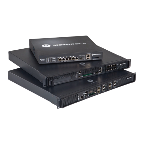
1 - 2 WiNG 4.4 Switch System Reference Guide 1.1 Hardware Overview The RFS4000, RFS6000 and RFS7000 are rack-mountable devices that manage all inbound and outbound traffic on the wireless network. They provide security, network service and system management applications. - Page 19 A minimum of one category 6 Ethernet cables (not supplied) are required to connect the switch to the LAN and WLAN. The cable(s) are used with the Ethernet ports on the front panel of the switch. Switch Note: On an RFS6000 and RFS7000, Motorola Solutions recommends connecting via the Management Ethernet (ME) interface to better ensure secure and easier manage- ment.
-
Page 20: Software Overview
Motorola Solutions RFMS can help optimize the positioning and configuration of a switch in respect to a WLAN’s MU throughput requirements and can help detect rogue devices. - Page 21 Overview 1 - 5 1.2.1.2 Configuration Management The switch supports the redundant storage of configuration files to protect against corruption during a write operation and ensure (at any given time) a valid configuration file exists. If writing the configuration file fails, it is rolled back and a pre- write file is used.
- Page 22 1 - 6 WiNG 4.4 Switch System Reference Guide 1.2.1.6 Process Monitor The switch Process Monitor checks to ensure processes under its control are up and running. Each monitored process sends periodic heartbeat messages. A process that is down (due to a software crash or stuck in an endless loop) is detected when its heartbeat is not received.
-
Page 23: Wireless Switching
Overview 1 - 7 To contact Motorola Solutions Support in the event of a password reset requirement, go to http://www.motorola.com/ Business/US-EN/Support CAUTION: Only a qualified installation professional should set or restore the access point’s radio and power management configuration in the event of a password reset. - Page 24 It can also provide differential service for service providers. The uplink and downlink rate limits are usually configured on the radius server using Motorola Solutions vendor specific attributes. The switch extracts the rate limits from radius server response. When such attributes are not present, the global settings on...
- Page 25 Overview 1 - 9 1.2.2.4 Proxy-ARP Proxy ARP is provided for MU's whose IP address is known. The WLAN generates an ARP reply on behalf of a MU (if the MU's IP address is known). The ARP reply contains the MAC address of the MU (not the MAC address of switch). Thus, the MU does not awaken to send ARP replies (increasing MU battery life and conserving wireless bandwidth).
- Page 26 1 - 10 WiNG 4.4 Switch System Reference Guide • Strict priority - The prioritization is strict. • Multicast prioritization - Multicast frames that match a configured multicast mask bypass the PSP queue. This features permits intercom mode operation without delay (even in the presence of PSP MU's).
- Page 27 • 802.11e admission control — 1 byte: channel utilization % and 1 byte: MU count is sent in QBSS Load Element in beacons to MU. • Motorola Solutions load balancing element (proprietary) — 2 byte: MU Count are sent in beacon to MU. For more information on Access Port adoption in a layer 3 environment, see...
- Page 28 The wireless switch supports international roaming per the 802.11d specification. MU Move Command As a value added proprietary feature between Motorola Solutions infrastructure products and Motorola Solutions MUs, a move command has been introduced. The move command permits an MU to roam between ports connected to the same switch without the need to perform the full association and authentication defined by the 802.11 standard.
- Page 29 Overview 1 - 13 1.2.2.12 Power Save Polling An MU uses Power Save Polling (PSP) to reduce power consumption. When an MU is in PSP mode, the switch buffers its packets and delivers them using the DTIM interval. The PSP-Poll packet polls the AP for buffered packets. The PSP null data frame is used by the MU to signal the current PSP state to the AP.
- Page 30 1 - 14 WiNG 4.4 Switch System Reference Guide Data QoS The switch supports the following data QoS techniques: • Egress Prioritization by WLAN • Egress Prioritization by ACL DCSCP to AC Mapping The switch provides arbitrary mapping between Differentiated Services Code Point (DCSCP) values and WMM Access Categories.
- Page 31 Overview 1 - 15 Limiting Users Per VLAN Not all VLANs within a single WLAN must have the same DHCP pool size. Assign a user limit to each VLAN to allow the mapping of different pool sizes. Specify the VLAN user limit. This specifies the maximum number of MUs associated with a VLAN (for a particular WLAN). When the maximum MU limit is reached, no more MUs can be assigned to that VLAN.
-
Page 32: Wired Switching
1 - 16 WiNG 4.4 Switch System Reference Guide 1.2.3 Wired Switching The switch includes the following wired switching features: • DHCP Servers • DHCP User Class Options • DDNS • VLAN Enhancements • Interface Management 1.2.3.1 DHCP Servers Dynamic Host Configuration Protocol (DHCP) allows hosts on an IP network to request and be assigned IP addresses as well as discover information about the network to which they are attached. -
Page 33: Management Features
• A Command Line Interface (CLI) accessible via the serial port or through Telnet or a Secure Shell (SSH) application • A CLI Service mode enabling the capture of system status information that can be sent to Motorola Solutions personnel for use in problem resolution •... -
Page 34: Security Features
1 - 18 WiNG 4.4 Switch System Reference Guide 1.2.5 Security Features Switch security can be classified into wireless security and wired security. The switch includes the following wireless security features: • Encryption and Authentication • MU Authentication • Secure Beacon •... - Page 35 WEP) developed a non standard method of rotating keys to prevent compromises. Basically, KeyGuard is TKIP without the message integrity check. KeyGuard is proprietary to Motorola Solutions MUs only. For information on configuring KeyGuard for a WLAN, see Configuring WEP 128 / KeyGuard on page 4-54.
- Page 36 1 - 20 WiNG 4.4 Switch System Reference Guide 1.2.5.3 Secure Beacon Devices in a wireless network use Service Set Identifiers (SSIDs) to communicate. An SSID is a text string up to 32 bytes long. An AP in the network announces its status by using beacons. To avoid others from accessing the network, the most basic security measure adopted is to change the default SSID to one not easily recognizable, and disable the broadcast of the SSID.
- Page 37 Overview 1 - 21 1.2.5.6 WIPS The Motorola Solutions Wireless Intrusion Protection Software (WIPS) monitors for any presence of unauthorized rogue Access Points. Unauthorized attempts to access the WLAN is generally accompanied by anomalous behavior as intruding MUs try to find network vulnerabilities. Basic forms of this behavior can be monitored and reported without needing a dedicated WIPS.
- Page 38 After determining which are authorized APs and which are Rogue, the switch prepares a report. Motorola Solutions RFMS Support With this most recent switch firmware release, the switch can provide rogue device detection data to the Motorola Solutions RF Management software application (or Motorola Solutions RFMS). Motorola Solutions RFMS uses this data to refine the position and display the rogue on a site map representative of the physical dimensions of the actual radio coverage area of the switch.
- Page 39 Overview 1 - 23 • MAC Extended ACLs • Wireless LAN ACLs For information on creating an ACL, see Configuring Firewalls and Access Control Lists on page 6-15. 1.2.5.9 Local Radius Server Radius is a common authentication protocol utilized by the 802.1x wireless security standard. Radius improves the WEP encryption key standard, in conjunction with other security methods such as EAP-PEAP.
-
Page 40: Supported Access Ports/Points
NAC support, see Configuring NAC Server Support on page 4-50. 1.2.6 Supported Access Ports/Points A RF switch supports the adoption of the following Motorola Solutions Enterprise Access Ports and Access Points: • AP100 • AP300 • AP-4131 •... -
Page 41: Ieee Standards Support
Overview 1 - 25 1.3 IEEE Standards Support IEEE Standard Supported Notes IEEE 802.11a Yes The IEEE 802.11a standard is fully supported on the following Switch Platforms: • WS2000 • WS5100 • RFS6000 • RFS7000 The IEEE 802.11a standard is fully supported on the following AP Platforms: •... - Page 42 1 - 26 WiNG 4.4 Switch System Reference Guide IEEE Standard Supported Notes IEEE 802.11d Yes The IEEE 802.1d standard is implemented as part of the IEEE 802.1s standard on the following Switch Platforms: • WS5100 • RFS6000 • RFS7000 The IEEE 802.11d standard is implemented for Mesh networking on the following AP Platforms:...
- Page 43 Overview 1 - 27 IEEE Standard Supported Notes IEEE 802.1x Full support IEEE 802.1x authentication ether with a fully functional integrated RADIUS server built into our RF Switches and Access Points or an external RADIUS server such as Microsoft IAS, Microsoft NPS, Cisco Secure ACS, Free RADIUS and Juniper Steel Belted RADIUS (to name a few).
- Page 44 1 - 28 WiNG 4.4 Switch System Reference Guide IEEE Standard Supported Notes IEEE 802.3ab Yes The IEEE 802.3ab (1000BASE-T) standard is fully supported on the following Switch Platforms: • RFS6000 • RFS7000 The IEEE 802.3ab (1000BASE-T) standard is fully supported on the following AP Platforms: •...
-
Page 45: Standards Support
Overview 1 - 29 1.4 Standards Support Standard Supported Notes RFC 768 UDP The RF Switch supports IP, UDP, TCP for various management and control functions and Switch -> AP communications. RFC 791 IP In addition we provide full IP4 routing support on the RF Switch as well as support IPv4 on our wired / wireless stateful inspection firewall. - Page 46 1 - 30 WiNG 4.4 Switch System Reference Guide Standard Supported Notes RFC 3602 The AES-CBC Cipher Algorithm and Its Use with IPsec SSL and TLS: RC4 128-bit and RSA 1024- and 2048-bit IPSec: DES-CBC, 3DES, AES-CBC RFC 2548 Microsoft Vendor-Specific...
- Page 47 Overview 1 - 31 Standard Supported Notes RFC 2863 Interfaces Group MIB We support ifTable but do not support ifMIB (mib-2 dot 31) which are later extensions of ifTable (mib-2 dot 2 dot 2). RFC 3164 Syslog RFC 3414 User-Based Security Model (USM) for SNMPv3 RFC 3418 MIB for SNMP Web-based: HTTP/HTTPS...
- Page 48 1 - 32 WiNG 4.4 Switch System Reference Guide...
-
Page 49: Chapter 2 Switch Web Ui Access And Image Upgrades
CHAPTER 2 SWITCH WEB UI ACCESS AND IMAGE UPGRADES The content of this chapter is segregated amongst the following: • Accessing the Switch Web UI • Switch Password Recovery • Upgrading the Switch Image • Auto Installation • AP-4131 Access Point to Access Port Conversion... -
Page 50: Accessing The Switch Web Ui
2 - 2 WiNG 4.4 Switch System Reference Guide 2.1 Accessing the Switch Web UI 2.1.1 Web UI Requirements The switch Web UI is accessed using Internet Explorer version 5.5 (or later) and SUN JRE (Java Runtime Environment) 1.5 (or later). Refer to the Sun Microsystems Web site for information on downloading JRE. - Page 51 This warning screen will continue to display on future login attempts until a self-signed certificate is implemented. Motorola Solutions recommends only using the default certificate for the first few login attempts until a self-signed certificate can be generated.
-
Page 52: Switch Password Recovery
Only an installation professional should reset the access point’s password and promptly define a new restrictive password. To contact Motorola Solutions Support in the event of a password reset requirement, go to http://www.motorola.com/... -
Page 53: Upgrading The Switch Image
The switch ships with a factory installed firmware image with the full feature functionality described in this System Reference Guide. However, Motorola Solutions periodically releases switch firmware that includes enhancements or resolutions to known issues. Verify your current switch firmware version with the latest version available from the... -
Page 54: Auto Installation
2 - 6 WiNG 4.4 Switch System Reference Guide 2.4 Auto Installation The switch auto install function can be configured manually or using a DHCP server. When configuring auto installation using DHCP, the server requires the definition of a vendor class and four sub-options under option 43 namely: •... - Page 55 Switch Web UI Access and Image Upgrades 2 - 7 Enables are set using the autoinstall <feature> command: RF Switch>en RF Switch#conf t RF Switch(config)#autoinstall image RF Switch(config)#autoinstall config RF Switch(config)#autoinstall cluster-config After this configuration update, any switch reboot with DHCP enabled on the RON port will trigger an auto install, provided the DHCP Server is configured with appropriate options.
-
Page 56: Ap-4131 Access Point To Access Port Conversion
To convert an AP-4131 “fat” Access Point to a “thin” AP-4131 Access Port you need to load the port conversion version firmware. Refer to the files available with you Motorola Solutions Website download package. To convert an AP-4131 Access Point 1. - Page 57 Switch Web UI Access and Image Upgrades 2 - 9 6. Select the Special Functions main menu item. 7. Select the Firmware Update Menu-[F3] menu item 8. Select the Alter Filename(s)/HELP URL/TFTP Server menu item. a. Confirm that the Firmware File Name is correct, make changes as needed. b.
- Page 58 2 - 10 WiNG 4.4 Switch System Reference Guide...
-
Page 59: Chapter 3 Switch Information
CHAPTER 3 SWITCH INFORMATION This chapter describes the Switch main menu information used to configure the switch. This chapter consists of the following sections: • Viewing the Switch Interface • Viewing Switch Port Information • Viewing Switch Configurations • Viewing Switch Firmware Information •... -
Page 60: Viewing The Switch Interface
Motorola Solutions RFMS can help optimize the positioning and configuration of a switch (and its associated radios) in respect to a WLAN’s MU throughput requirements and can help detect rogue devices. For more information, refer to the Motorola Solutions Website. - Page 61 Uptime is the cumulative time since the switch was last rebooted or lost power. Firmware Displays the current firmware version running on the switch. This version should be periodically compared to the most recent version available on the Motorola Solutions Website, as versions with increased functionality are periodically released. AP License Count Displays the number of Access Port licenses currently available for the switch.
-
Page 62: Switch Dashboard Details
3.1.3 Switch Dashboard Details Each Motorola Solutions RF Switch platform contains a dashboard which represents a high-level graphical overview of central switch processes and hardware. When logging into the switch, the dashboard should be the first place you go to assess overall switch performance and any potential performance issues. - Page 63 Switch Information 3 - 5 3.1.3.1 RFS4000 Switch Dashboard Dashboard screen displays the current health of the switch and is divided into fields representing the following important diagnostics: • Alarms • Ports • Environment • CPU/Memory • File Systems Apart from the sections mentioned above, it also displays the following status: Redundancy State Displays the Redundancy State of the switch.
- Page 64 3 - 6 WiNG 4.4 Switch System Reference Guide Mobile Units Displays the total number of MUs associated with the switch. Up Time Displays the actual switch uptime. The Uptime is the current operational time of the device defined within the System Name field. Uptime is the cumulative time since the switch was last rebooted or lost power.
- Page 65 Switch Information 3 - 7 3.1.3.2 RFS6000 Switch Dashboard Dashboard screen displays the current health of the switch and is divided into fields representing the following important diagnostics: • Alarms • Ports • Environment • CPU/Memory • File Systems Apart from the sections mentioned above, it also displays the following status: Redundancy State Displays the Redundancy State of the switch.
- Page 66 3 - 8 WiNG 4.4 Switch System Reference Guide Mobile Units Displays the total number of MUs associated with the switch. Up Time Displays the actual switch uptime. The Uptime is the current operational time of the device defined within the System Name field. Uptime is the cumulative time since the switch was last rebooted or lost power.
- Page 67 Switch Information 3 - 9 3.1.3.3 RFS7000 Switch Dashboard Dashboard screen displays the current health of the switch and is divided into fields representing the following important diagnostics: • Alarms • Ports • Environment • CPU/Memory • File Systems Apart from the sections mentioned above, it also displays the following status: Redundancy State Displays the Redundancy State of the switch.
- Page 68 3 - 10 WiNG 4.4 Switch System Reference Guide Mobile Units Displays the total number of MUs associated with the switch. Up Time Displays the actual switch uptime. The Uptime is the current operational time of the device defined within the System Name field. Uptime is the cumulative time since the switch was last rebooted or lost power.
-
Page 69: Viewing Switch Statistics
Switch Information 3 - 11 3.1.4 Viewing Switch Statistics Switch Statistics tab displays an overview of the recent network traffic and RF status for the switch. To display the Switch Statistics tab: 1. Select Switch from the main menu tree. 2. - Page 70 3 - 12 WiNG 4.4 Switch System Reference Guide Avg. Bit Speed Displays the average bit speed for the switch over last 30 seconds and 1 hour. Use the average bit speed value to help determine overall network speeds and troubleshoot network congestion.
-
Page 71: Viewing Switch Port Information
Switch Information 3 - 13 3.2 Viewing Switch Port Information Port screen displays configuration, runtime status, and statistics of the ports on the switch. Switch Note: The ports available vary by switch platform. RFS6000: ge1, ge2, ge3, ge4, ge5, ge6, ge7, ge8, me1, up1 RFS7000: ge1, ge2, ge3, ge4, me1 RFS4000: ge1, ge2, ge3, ge4, ge5, up1 The port types are defined as follows:... - Page 72 3 - 14 WiNG 4.4 Switch System Reference Guide 2. Select the Configuration tab to display the following read-only information: Name Displays the current port name. The port names available vary by switch. RFS6000: ge1, ge2, ge3, ge4, ge5, ge6, ge7, ge8, me1, up1, wan RFS7000: ge1, ge2, ge3, ge4, me1 RFS4000: ge1, ge2, ge3, ge4, ge5.
- Page 73 Switch Information 3 - 15 3.2.1.1 Editing the Port Configuration To modify the port configuration: 1. Select a port from the table displayed within the Configuration screen. 2. Click the Edit button. Port Change Warning screen displays, stating any change to the port setting could disrupt access to the switch. Communication errors may occur even if modifications made are successful.
-
Page 74: Viewing The Ports Runtime Status
3 - 16 WiNG 4.4 Switch System Reference Guide Name Displays the read-only name assigned to the port. Speed Select the speed at which the port can receive and transmit the data. Select from the following range: • 10 Mbps •... -
Page 75: Reviewing Port Statistics
Switch Information 3 - 17 2. Select the Runtime tab to display the following read-only information: Name Displays the port’s current name. MAC Address Displays the port’s MAC Address. This value is read-only, set at the factory and cannot be modified. - Page 76 3 - 18 WiNG 4.4 Switch System Reference Guide 2. Select the Statistics tab. 3. Refer to the Statistics tab to display the following read-only information: Name Defines the port name. The port names available vary by switch. RFS6000: ge1, ge2, ge3, ge4, ge5, ge6, ge7, ge8, me1, up1, wan...
- Page 77 Switch Information 3 - 19 3.2.3.1 Detailed Port Statistics To view detailed statistics for a port: 1. Select a port from the table displayed within the Statistics screen. 2. Click the Details button. 3. The Interface Statistics screen displays. This screen displays the following statistics for the selected port: Name Displays the port name.
- Page 78 3 - 20 WiNG 4.4 Switch System Reference Guide Output NonUnicast Displays the number of unicast packets transmitted from the interface. Packets Output Total Displays the total number of packets transmitted from the interface. Packets Output Packets Displays the number of transmitted packets dropped from the interface. Output Packets Dropped...
-
Page 79: Power Over Ethernet (Poe)
Switch Information 3 - 21 • Output Pkts Error • Input Pkts Total • Input Pkts Error • Output Pkts NUCast • Input Pkts NUCast • Output Bytes • Output Pkts Dropped 3. Display any of the above by selecting the checkbox associated with it. NOTE: You are not allowed to select (display) more than four parameters at any given time. - Page 80 3 - 22 WiNG 4.4 Switch System Reference Guide 2. Select the Switch Note: The PoE screen is available on the RF6000 and RFS4000 switches. The RFS7000 switch does not have Power over Ethernet on any ports and will not display the PoE tab.
-
Page 81: Editing Port Poe Settings
Switch Information 3 - 23 Priority Displays the priority mode for each of the PoE ports. The priority options are: • Critical • High • Low Limit (watts) Displays the power limit in watts for each of the PoE ports. The maximum power limit per port is 36 watts. -
Page 82: Configuring Wan Interface Cards
3 - 24 WiNG 4.4 Switch System Reference Guide 3.2.6 Configuring WAN Interface Cards The RFS6000 switch supports 3G Wireless WAN cards using the ExpressCard slot. In order to use a 3G Wireless WAN card with the switch, it must first be initialized on a laptop. For activation and initialization information, refer to the instructions included with the card. - Page 83 Switch Information 3 - 25 4. To reset the WAN Interface card configuration, click the Reset button and the configuration fields will be cleared.
-
Page 84: Viewing Switch Configurations
Motorola Solutions RFMS can help optimize the positioning and configuration of a switch (and its associated radios) in respect to a WLAN’s MU throughput requirements and can help detect rogue devices. -
Page 85: Viewing The Detailed Contents Of A Config File
3.3.1 Viewing the Detailed Contents of a Config File The View screen displays the entire contents of a configuration file. Motorola Solutions recommends a file be reviewed carefully before it is selected from the Config Files screen for edit or designation as the switch startup configuration. -
Page 86: Transferring A Config File
3 - 28 WiNG 4.4 Switch System Reference Guide Use the up and down navigation facilities on the right-hand side of the screen to view the entire page. 3. The Page parameter displays the portion of the configuration file in the main viewing area. - Page 87 Switch Information 3 - 29 2. Refer to the Source field to define the location and address information for the source config file. From Select the location representing the source file’s current location using the From drop-down menu. Options include Server, Local Disk, and Switch.
-
Page 88: Viewing Switch Firmware Information
3 - 30 WiNG 4.4 Switch System Reference Guide 3.4 Viewing Switch Firmware Information The switch can store (retain) two software versions (primary and secondary). Information supporting the two versions displays within the Firmware screen. The Version column displays the version string. The... -
Page 89: Editing The Switch Firmware
Switch Information 3 - 31 4. Select an existing firmware version and click the Edit button to change the firmware version used when the switch is booted next. For more information, see Editing the Switch Firmware on page 3-31. 5. Click on the Global Settings button to specify a firmware version for use with the failover image. -
Page 90: Updating The Switch Firmware
3 - 32 WiNG 4.4 Switch System Reference Guide 3. Select the Enable Image Failover checkbox to load an alternative firmware version if the WLAN module fails to load the selected version successfully after 2 reboot attempts. 4. Refer to the Status field for the current state of the requests made from the applet. - Page 91 Switch Information 3 - 33 c. Use HTTP to get the firmware update from a Hyper Text Transfer Protocol (HTTP) server. d. Use SFTP to get the firmware update from a Secure File Transfer Protocol (SFTP) server. A user account must be established on the SFTP server specified for the firmware update.
-
Page 92: Switch File Management
3 - 34 WiNG 4.4 Switch System Reference Guide 3.5 Switch File Management Use the File Management screen to transfer configuration file to and from the switch and review the files available. 3.5.1 Transferring Files Use the Transfer Files screen to transfer files to and from the switch.Transferring files is recommended to keep files in a secure location. - Page 93 Switch Information 3 - 35 3.5.1.1 Transferring a file from Wireless Switch to Wireless Switch To transfer a file from one switch to another: 1. Select Wireless Switch from the From drop-down menu 2. Use the Browse button to locate a target file for the file transfer. 3.
- Page 94 3 - 36 WiNG 4.4 Switch System Reference Guide 3.5.1.2 Transferring a File from a Wireless Switch to a Server To transfer a file from the Switch to a Server: 1. Refer to the Source field to specify the source file. Use the From drop-down menu and select Wireless Switch.
-
Page 95: Viewing Files
Switch Information 3 - 37 3.5.1.3 Transferring a File from a Server to a Wireless Switch To transfer a file from a Server to the switch: 1. Refer to the Source field to specify the details of the source file. Use the From drop-down menu and select Server. - Page 96 3 - 38 WiNG 4.4 Switch System Reference Guide • USB 1 • USB 2 Switch Note: USB 1 is available on the RFS6000 and RFS7000 switches. USB2 and Com- pact Flash are only available on the RFS7000 switch. Transfer files between the switch and the server from any one of the above mentioned locations. Since compact flash (CF) and USB are external memory locations, the File System window displays the status of these devices.
-
Page 97: Configuring Automatic Updates
Enable this option for either the firmware, configuration file, or cluster configuration file. Motorola Solutions recommends leaving this setting disabled if a review of a new file is required before it is automatically uploaded by the switch. - Page 98 3 - 40 WiNG 4.4 Switch System Reference Guide 3. Refer to the Redundancy Configuration field to enable and define the configuration for automatic cluster file updates. Enable Select the Enable checkbox to allow an automatic cluster file update when a new (updated) file is detected (upon the boot of the switch) at the specified IP address.
-
Page 99: Viewing The Switch Alarm Log
Switch Information 3 - 41 3.7 Viewing the Switch Alarm Log Use the Alarm Log screen as an initial snapshot for alarm log information. Expand alarms (as needed) for greater detail, delete alarms, acknowledge alarms, or export alarm data to a user-specified location for archive and network performance analysis. -
Page 100: Viewing Alarm Log Details
3 - 42 WiNG 4.4 Switch System Reference Guide Severity Displays the severity level of the event. Use this (non numerical and verbal) description to assess the criticality of the alarms. Severity levels include: • Critical • Major • Warning •... - Page 101 Switch Information 3 - 43 3. Refer to the Alarm Details Alarm Message for the following information: Description Displays the details of the alarm log event. This information can be used in conjunction with the Solution Possible Causes items to troubleshoot the event and determine how the event can be avoided in future.
-
Page 102: Viewing Switch Licenses
3 - 44 WiNG 4.4 Switch System Reference Guide 3.8 Viewing Switch Licenses Use the Licenses screen to install and add a new switch license. Switch Note: By default the following licenses are automatically activated on RFS4000 switches: • 6 AP licenses, which will work for Access Ports or Adaptive APs •... - Page 103 Switch Information 3 - 45 4. Refer to the Feature Licenses table for the following license specific information: Feature Name Displays the name of the feature either installed or upgraded on the switch. Available feature licenses on the switch are: •...
-
Page 104: How To Use The Filter Option
3 - 46 WiNG 4.4 Switch System Reference Guide 3.9 How to use the Filter Option Use the Filter Option to sort the display details of screen that employ the filtering option as a means of sorting how data is displayed within the screen. -
Page 105: Chapter 4 Network Setup
CHAPTER 4 NETWORK SETUP This chapter describes the Network Setup menu information used to configure the switch. This chapter consists of the following switch Network configuration activities: • Displaying the Network Interface • Viewing Network IP Information • Viewing and Configuring Layer 2 Virtual LANs •... -
Page 106: Displaying The Network Interface
4 - 2 WiNG 4.4 Switch System Reference Guide 4.1 Displaying the Network Interface The main Network interface displays a high-level overview of the configuration (default or otherwise) as defined within the Network main menu. Use the information to determine if items require additional configuration using the sub-menu items under the main Network menu item. - Page 107 Network Setup 4 - 3 2. Refer to the following information to discern if configuration changes are warranted: DNS Servers Displays the number of DNS Servers configured thus far for use with the switch. For more information, see Viewing Network IP Information on page 4-4.
-
Page 108: Viewing Network Ip Information
4 - 4 WiNG 4.4 Switch System Reference Guide 4.2 Viewing Network IP Information Use the Internet Protocol screen to view and configure network-associated IP details. The Internet Protocol screen contains tabs supporting the following configuration activities: • Configuring DNS •... - Page 109 Network Setup 4 - 5 6. Click the Global Settings button to open a screen that allows the domain lookup to be enabled/disabled and the domain name to be specified. For more information, see Configuring Global Settings on page 4-5. 4.2.1.1 Adding an IP Address for a DNS Server Add an IP address for a new domain server using the screen.
-
Page 110: Configuring Ip Forwarding
4 - 6 WiNG 4.4 Switch System Reference Guide 4.2.2 Configuring IP Forwarding The IP Forwarding table lists all the routing entries to route the packets to a specific destination. To view the IP forwarding configuration: 1. Select Network >... - Page 111 Network Setup 4 - 7 Protocol Displays the name of the routing protocol with which this route was obtained. Possible values are: • Static — Routes are statically added by the operator. • DHCP — Routes obtained from the DHCP server. •...
-
Page 112: Viewing Address Resolution
4 - 8 WiNG 4.4 Switch System Reference Guide 4.2.3 Viewing Address Resolution Address Resolution table displays the mapping of layer three (IP) addresses to layer two (MAC) addresses. To view address resolution details: 1. Select Network > Internet Protocol from the main tree menu. -
Page 113: Viewing And Configuring Layer 2 Virtual Lans
Network Setup 4 - 9 4.3 Viewing and Configuring Layer 2 Virtual LANs A virtual LAN (VLAN) is similar to a Local Area Network (LAN), however devices do not need to be connected to the same segment physically. Devices operate as if connected to the same LAN, but could be connected at different physical connections across the LAN segment. -
Page 114: Editing The Details Of An Existing Vlan By Port
4 - 10 WiNG 4.4 Switch System Reference Guide Allowed VLANs Displays VLAN tags allowed on this interface Tagged Native Displays if the Native VLAN for each port is tagged or not. The column displays a green VLAN check mark if the Native VLAN is tagged. If the Native VLAN is not tagged, the column will display a red “x”. -
Page 115: Viewing And Configuring Ports By Vlan
Network Setup 4 - 11 4. Use the Edit screen to modify the VLAN’s mode, access VLAN, and allowed VLAN designation. 5. Use the Edit screen to modify the following: Name Displays a read-only field and with the name of the Ethernet to which the VLAN is associated. - Page 116 4 - 12 WiNG 4.4 Switch System Reference Guide 2. Select the Ports by VLAN tab. VLAN details are displayed within the VLANs by Port tab. 3. Highlight an existing VLAN and click the Edit button. The system displays a...
- Page 117 Network Setup 4 - 13 7. Click Cancel to close the dialog without committing updates to the running configuration.
-
Page 118: Configuring Switch Virtual Interfaces
4 - 14 WiNG 4.4 Switch System Reference Guide 4.4 Configuring Switch Virtual Interfaces A Switch Virtual Interface (SVI) is required for layer 3 (IP) access to the switch or to provide layer 3 service on a VLAN. The SVI defines which IP address is associated with each VLAN ID that the switch is connected to. An SVI is created for the default VLAN (VLAN 1) to enable remote switch administration. - Page 119 Network Setup 4 - 15 Primary Subnet Displays the subnet mask assigned for this interface. Mask Admin Status Displays whether the virtual interface is operational and available to the switch. Oper Status Displays whether the selected Switch Virtual Interface is currently (Up) or not (Down) on the switch.
- Page 120 4 - 16 WiNG 4.4 Switch System Reference Guide 3. Click the button. 4. Enter the VLAN ID for the switch virtual interface. 5. Provide a Description for the VLAN, representative of the VLAN’s intended operation within the switch managed network.
-
Page 121: Viewing Virtual Interface Statistics
Network Setup 4 - 17 2. Select the Configuration tab and click the Edit button. The screen displays with the name of the VLAN in the upper left-hand side. The VLAN ID cannot be modified and should be used to associate the VLAN ID with the description and IP address assignments defined. 3. - Page 122 4 - 18 WiNG 4.4 Switch System Reference Guide 2. Select the Statistics tab. Refer to the following to assess the network throughput of existing virtual interfaces: Name Displays the user-defined interface name. The corresponding statistics are displayed along the row. The statistics are the total traffic to the interface since its creation.
- Page 123 Network Setup 4 - 19 Packets Out Displays the number of packets going out on the interface. Packets Out Displays the number of dropped packets going out of the interface due to saturated Dropped output queues assigned to the interface processor or the physical device/software module.
- Page 124 4 - 20 WiNG 4.4 Switch System Reference Guide Input Packets Displays the number of packets dropped at the interface by the input Queue of the hardware Dropped unit /software module associated with the VLAN interface. Packets are dropped when the input Queue of the interface is full or unable to handle incoming traffic.
- Page 125 Network Setup 4 - 21 • Input Pkts Error • Output Pkts NUCast • Input Pkts NUCast • Output Bytes • Output Pkts Dropped Select any of the above parameters by clicking on the checkbox associated with it. NOTE: Only four parameters may be selected at any given time. 4.
-
Page 126: Viewing And Configuring Switch Wlans
4 - 22 WiNG 4.4 Switch System Reference Guide 4.5 Viewing and Configuring Switch WLANs A wireless LAN (WLAN) is a local area network (LAN) without wires. WLANs transfer data through the air using radio frequencies instead of cables. The WLAN screen displays a high-level overview of the WLANs created for the switch managed network. - Page 127 Network Setup 4 - 23 2. Click the Configuration tab. Configuration tab displays the following details: Switch Switch field displays the IP address of the cluster member associated with each WLAN. When clustering is enabled on the switch and Cluster GUI is enabled, the Switch field will be available on the Wireless LAN screen.
- Page 128 4 - 24 WiNG 4.4 Switch System Reference Guide Encryption Displays the type of wireless encryption used on the specified WLAN. When no encryption is used, the field displays "none". Click the Edit button to modify the WLAN’s current encryption scheme. For information on configuring an authentication scheme for...
- Page 129 Network Setup 4 - 25 6. Click the Global Settings button to display a screen with WLAN settings applying to all the WLANs on the system. Remember, changes made to any one value impact each WLAN. Click to save updates to the Global WLAN Settings screen.
- Page 130 4 - 26 WiNG 4.4 Switch System Reference Guide Manual mapping of Use this option (it is selected by default) for custom WLAN to Radio mappings. WLANs When this option is disabled, the user cannot conduct Radio – WLAN mapping.
- Page 131 Network Setup 4 - 27 4.5.1.1 Editing the WLAN Configuration Security measures for the switch and its WLANs are critical. Use the available switch security options to protect each WLAN from wireless vulnerabilities, and secure the transmission of RF packets between WLANs and the MU traffic they support.
- Page 132 4 - 28 WiNG 4.4 Switch System Reference Guide • Authentication • Encryption • Advanced 5. The Switch field displays the IP address of the cluster member associated with each WLAN. When clustering is enabled on the switch and Cluster GUI is enabled, the Switch field will be available on the Wireless LAN screen.
- Page 133 Network Setup 4 - 29 SA Query Max Define the maximum time (in milliseconds) before an SA Query is timed out. The valid Timeout timeout range is between 100msec and 6000msec with a default value of 1000msec. SA Query Retry Define the maximum number of retries before an SA Query is timed out.
- Page 134 WEP 128 for the WLAN, see Configuring WEP 128 / KeyGuard on page 4-54. KeyGuard Uses a Motorola Solutions proprietary encryption mechanism to protect data. For detailed information on configuring KeyGuard for the WLAN, see Configuring WEP 128 / KeyGuard on page 4-54. WPA-WPA2-TKIP Use the WPA-TKIP checkbox to enable Wi-Fi Protected Access (WPA) with Temporal Key Integrity Protocol (TKIP).
- Page 135 Voice is used on the WLAN. This gives priority Prioritization to voice packets and voice management packets and is supported only on certain legacy Motorola Solutions VOIP phones. Enable SVP Enabling SVP (Spectralink Voice Prioritization) allows the switch to identify and prioritize traffic from Spectralink/Polycomm phones.
- Page 136 4 - 32 WiNG 4.4 Switch System Reference Guide MCast Addr 2 The second address also takes packets (where the first 4 bytes match the first 4 bytes of the mask) and sends them immediately over the air instead of waiting for the DTIM period. Any multicast/broadcast that does not match this mask will go out only on DTIM Intervals.
- Page 137 Network Setup 4 - 33 6. Configure the Multiple VLAN Mapping for WLAN table as required to add or remove multiple VLANS for the selected WLAN. Multiple VLANs per WLAN are mapped (by default) to a regular VLAN and are not supported on an adaptive AP. Refer Editing the WLAN Configuration on page 4-27 to select and define an independent VLAN for adaptive AP support.
- Page 138 4 - 34 WiNG 4.4 Switch System Reference Guide 4.5.1.3 Configuring Authentication Types Refer to the following to configure the WLAN authentication options available on the switch: • Configuring 802.1x EAP • Configuring Kerberos • Configuring Hotspots • Configuring an Internal Hotspot •...
- Page 139 Using Kerberos, an MU must prove its identity to a server (and vice versa) across an insecure network connection. Once an MU and server prove their identity, they can encrypt all communications to assure privacy and data integrity. Kerberos can only be used with Motorola clients.
- Page 140 4 - 36 WiNG 4.4 Switch System Reference Guide 6. Specify a case-sensitive Realm Name. The realm name is the name domain/realm name of the KDC Server. A realm name functions similarly to a DNS domain name. In theory, the realm name is arbitrary. However, in practice a Kerberos realm is named by uppercasing the DNS domain name associated with hosts in the realm.
- Page 141 Network Setup 4 - 37 browser after connecting to the WLAN), a protocol stack on the switch intercepts the request and sends back an HTTP response after modifying the network and port address in the packet (thereby acting like a proxy between the User and the Web site they are trying to access).
- Page 142 4 - 38 WiNG 4.4 Switch System Reference Guide 1. Select Network > Wireless LANs from the main menu tree. Select an existing WLAN from those displayed within Configuration tab and click the Edit button. 2. Select an existing WLAN from those displayed within the...
- Page 143 Network Setup 4 - 39 Main Logo URL Displays the URL for the main logo image displayed on the Failed page when using the switch’s internal Web server. This option is only available if Internal is chosen from the drop- down menu above.
- Page 144 4 - 40 WiNG 4.4 Switch System Reference Guide Main Logo URL The Main Logo URL is the URL for the main logo image displayed on the Failed page when using the internal Web server. This option is only available if...
- Page 145 Network Setup 4 - 41 12.Check the Logout on Browser Close button to log out hotspot users from the network when they close their web browsers. 13.Specify the maximum Hotspot Simultaneous Users to set a limit on the number of concurrent unique hotspot users for the selected WLAN.
- Page 146 4 - 42 WiNG 4.4 Switch System Reference Guide 3. Select the Hotspot button from within the Authentication field. Ensure External is selected from within the This WLAN’s Web Pages are of the drop-down menu. 4. Refer to the External Web Pages field and provide the Login, Welcome, and Failed Page URLs used by the external Web server to support the hotspot.
- Page 147 Network Setup 4 - 43 Failed Page URL Define the complete URL for the location of the Failed page. The Failed screen assumes that the hotspot authentication attempt has failed, you are not allowed to access the Internet and you need to provide correct login information to access the Web. For example, the Failed page URL can be the following: http://192.168.150.
- Page 148 4 - 44 WiNG 4.4 Switch System Reference Guide 16.Click Cancel to close the dialog without committing updates to the running configuration. NOTE: While using the External web pages option: 1. Configure the Internal Web pages for a particular WLAN.
- Page 149 Network Setup 4 - 45 4. Select the Hotspot button from within the Authentication field. Ensure Advanced is selected from within the This WLAN’s Web Pages are of the drop-down menu. Once the properties of the advanced hotspot have been defined, the file can be installed on the switch and used to support the hotspot.
- Page 150 4 - 46 WiNG 4.4 Switch System Reference Guide 7. Specify the maximum Hotspot Simultaneous Users to set a limit on the number of concurrent unique hotspot users for the selected WLAN. 8. Check the Logout on Browser Close button to log out hotspot users from the network when they close their web browsers.
- Page 151 To configure an external Radius Server for EAP 802.1x, Hotspot, or Dynamic MAC ACL WLAN support: NOTE: To optimally use an external Radius Server with the switch, Motorola Solutions recommends defining specific external Server attributes to best utilize user privilege values for specific switch permissions.
- Page 152 4 - 48 WiNG 4.4 Switch System Reference Guide 2. Select an existing WLAN from those displayed within the Configuration tab. 3. Click the Edit button. 4. Select either the EAP 802.1x, Hotspot, Dynamic MAC ACL button from within the Authentication field.
- Page 153 Network > Wireless LANs > Edit screen. Configuring an External Radius Server for Optimal Switch Support The switch’s external Radius Server should be configured with Motorola RF Switch specific attributes to best Solutions utilize the user privilege values assignable by the Radius Server.
- Page 154 4 - 50 WiNG 4.4 Switch System Reference Guide The following recommended Radius Server user privilege settings specify access privilege levels for those accessing the switch managed network. To define user privilege values, assign the following attributes in the external Radius Server: 1.
- Page 155 Network Setup 4 - 51 The switch supports only EAP/802.1x NAC. However, the switch provides a mean to bypass NAC authentication for MUs without NAC 802.1x support (printers, phones, PDAs, etc.). For a NAC configuration example using the switch CLI, see Configuring the NAC Inclusion List on page 4-68 Configuring the NAC Exclusion List on page 4-72.
- Page 156 4 - 52 WiNG 4.4 Switch System Reference Guide 7. Refer to the Server field and define the following credentials for a primary and secondary NAC server. NAC Server Address Enter the IP address of the primary and secondary NAC server.
- Page 157 Pass Key and click the Generate button. The pass key can be any alphanumeric string. The switch, other proprietary routers, and Motorola MUs use Solutions the algorithm to convert an ASCII string to the same hexadecimal number. MUs without Motorola...
- Page 158 WEP keys. WEP 128 may be all that a small-business user needs for the simple encryption of wireless data. KeyGuard is a proprietary encryption method developed by Motorola Technologies. KeyGuard is Motorola Solutions’ enhancement to WEP encryption, and was developed before the finalization of WPA-TKIP. This encryption implementation is based on the IEEE Wireless Fidelity (Wi-Fi) standard, 802.11i.
- Page 159 Pass Key and click the Generate button. The pass key can be any alphanumeric string. The switch and Motorola MUs use the algorithm to convert an Solutions ASCII string to the same hexadecimal number. MUs without Motorola adapters need to use WEP keys Solutions manually configured as hexadecimal numbers.
- Page 160 4 - 56 WiNG 4.4 Switch System Reference Guide Configuring WPA/WPA2 using TKIP and CCMP Wi-Fi Protected Access (WPA) is a robust encryption scheme specified in the IEEE Wireless Fidelity (Wi-Fi) standard, 802.11i. WPA provides more sophisticated data encryption than WEP. WPA is designed for corporate networks and small- business environments where more wireless traffic allows quicker discovery of encryption keys by an unauthorized person.
- Page 161 Network Setup 4 - 57 6. Refer to the Update broadcast keys every field to specify a time period (in seconds) for broadcasting encryption-key changes to MUs. Set key broadcasts to a shorter interval (at least 60 seconds) for tighter security on wireless connections. Set key broadcasts to a longer interval (at most, 86400 seconds) to extend key times for wireless connections.
-
Page 162: Viewing Wlan Statistics
4 - 58 WiNG 4.4 Switch System Reference Guide NOTE: Legacy MUs supporting WEP encryption and new MUs supporting 802.11i WPA/WPA2-TKIP encryption can not co-exist on the same WLAN. The multi-cipher support feature allows you to enable these two device types to co-exist on the same WLAN. - Page 163 Network Setup 4 - 59 2. Click the Statistics tab. 3. Refer to the following details displayed within the table: Last 30s Click the Last 30s radio button to display statistics for the WLAN over the last 30 seconds. This option is helpful when troubleshooting issues as they actually occur. Last Hr Click the Last Hr...
- Page 164 4 - 60 WiNG 4.4 Switch System Reference Guide 4. To view WLAN statistics in greater detail, select a WLAN and click the Statistics button. For more information, see Viewing WLAN Statistics in Detail on page 4-60. NOTE: When using mesh-enabled WLAN statistics, no statistics are shown. This is because WLAN statistics are generated by mobile unit traffic for that particular WLAN.
- Page 165 Network Setup 4 - 61 4. Refer to the Information field for the following information: ESSID Displays the Service Set ID (SSID) for the selected WLAN. VLAN Displays the name of the VLAN the WLAN is associated with. Num Associated Displays the total number of MUs currently associated with the selected WLAN.
- Page 166 4 - 62 WiNG 4.4 Switch System Reference Guide 7. Refer to the Errors field for the following information: Average Number of Displays the average number of retries for all MUs associated with the selected WLAN. The Retries number in black represents this statistics for the last 30 seconds and the number in blue represents this statistics for the last hour.
- Page 167 Network Setup 4 - 63 • TX Tput (Mbps) • NUcast Pkts • Avg Noise (dBm) • Undecr Pkts • RXPkts per sec • RX Tput (Mbps) • Avg Retries • Avg SNR (dB) • # Radios NOTE: You cannot select (and send) more than four parameters at any given time. 3.
-
Page 168: Configuring Wmm
1.0 to 54.0 Mbps. If a large number of packets are sent and received at a slower data rate, then perhaps the switch is not adequately positioned or configured to support the MUs within that WLAN. NOTE: The Motorola Solutions RF Management Software is recommended to plan the deployment of the switch. Motorola Solutions RFMS can help optimize the positioning and configuration of a switch in respect to a WLAN’s MU throughput requirements. - Page 169 Network Setup 4 - 65 WLAN enabled Displays the status of the WLAN. A Green check defines the WLAN as enabled and a Red "X" means it is disabled. The enable/disable setting can be defined using the WLAN Configuration screen. WMM enabled Displays WLAN-WMM status.
- Page 170 4 - 66 WiNG 4.4 Switch System Reference Guide 4. Select the QoS Mappings button to revise the existing mappings of access category to 802.1p and DSCP to access category settings. With a drastic increase in bandwidth absorbing network traffic (VOIP, multimedia, etc.), the importance of data prioritization is critical to effective network management.
- Page 171 Network Setup 4 - 67 4.5.3.1 Editing WMM Settings WLAN WMM configuration affects your upstream traffic parameters. Use Configuring WMM on page 4-108 to configure downstream traffic parameters. Use the WMM Edit screen to modify existing Access Category settings for the WLAN selected within the WMM screen.
-
Page 172: Configuring The Nac Inclusion List
4 - 68 WiNG 4.4 Switch System Reference Guide CW Minimum The CW Minimum is combined with the CW Maximum to make the Contention screen. From this range, a random number is selected for the back off mechanism. Select a lower value for high priority traffic. - Page 173 Network Setup 4 - 69 2. Select the NAC Include List Configuration tab to view and configure NAC enabled devices. 3. The Include Lists field displays the list of devices that can be included on a WLAN (a printer for example). Use the button to add a device for configuration on a WLAN.
- Page 174 4 - 70 WiNG 4.4 Switch System Reference Guide 4.5.4.1 Adding an Include List to a WLAN To add a device to a WLAN’s include list configuration: 1. Select Network > Wireless LANs from the main menu tree. 2. Select the NAC Include tab to view and configure NAC Include enabled devices.
- Page 175 Network Setup 4 - 71 9. Click Cancel to close the dialog without committing updates to the running configuration. 4.5.4.3 Mapping Include List Items to WLANs To assign include list items to one or more WLANs: 1. Select Network > Wireless LANs from the main menu tree.
-
Page 176: Configuring The Nac Exclusion List
4 - 72 WiNG 4.4 Switch System Reference Guide 4.5.5 Configuring the NAC Exclusion List The switch provides a means to bypass NAC for 802.1x devices without a NAC agent. For Motorola Solutions handheld devices (like the MC9000), authentication is achieved using an exclusion list. - Page 177 Network Setup 4 - 73 6. To delete a device, select a device from the Exclude List and click the Delete button. 7. Use the Edit button to modify devices parameters. 8. To delete a list configuration for a device, select a row from the List Configuration field and click the Delete...
-
Page 178: Nac Configuration Examples Using The Switch Cli
The following are NAC include list, exclude list, and WLAN configuration examples using the switch CLI interface: 4.5.6.1 Creating an Include List Since few devices require NAC, Motorola Solutions recommends using the "bypass-nac-except-include-list" option. Refer to the commands below to create a NAC Include List:... - Page 179 Network Setup 4 - 75 1. Create a NAC include list. RF Switch (config-wireless) #client include-list Desktop RF Switch (config-wireless-client-list) # NOTE: The instance changes from (config-wireless) (config-wireless- client-list) 2. Add a host entry to the include list. This adds a specified MAC entry/MAC range into the client’s include list. RF Switch(config-wireless-client-list) #station pc1 AA:BB:CC:DD:EE:FF RF Switch(config-wireless-client-list) # 3.
- Page 180 4 - 76 WiNG 4.4 Switch System Reference Guide RF Switch(config-wireless) # NOTE: Configure the secondary NAC server for redundancy. c. Configure the secondary NAC server’s IP address. RF Switch(config-wireless) #wlan 1 nac-server secondary 192.168.1.20 RF Switch(config-wireless) # d. Configure the secondary NAC Server’s Radius Key.
-
Page 181: Viewing Associated Mu Details
Viewing MU Voice Statistics NOTE: The Motorola Solutions RF Management Software is a recommended utility to plan the deployment of the switch and view its configuration once operational. Motorola Solutions RFMS can help optimize switch positioning and configuration in respect to a WLAN’s MU throughput requirements and can help detect rogue devices. - Page 182 4 - 78 WiNG 4.4 Switch System Reference Guide IP Address Displays the unique IP address for the MU. Use this address as necessary throughout the applet for filtering and device intrusion recognition and approval. Ready Displays whether the MU is ready for switch interoperation. Values are Yes and No.
- Page 183 Network Setup 4 - 79 3. Select a MU from the table in the Status screen and click the Details button. 4. Refer to the following read-only MU’s transmit and receive statistics:. MAC Address Displays the Hardware or Media Access Control (MAC) address for the MU. IP Address Displays the unique IP address for the MU.
- Page 184 4 - 80 WiNG 4.4 Switch System Reference Guide Voice Displays whether or not the MU is a voice capable device. Traffic from a voice enabled MU is handled differently than traffic from MUs without this capability. MUs grouped to particular WLANs can be prioritized to transmit and receive voice traffic over data traffic.
-
Page 185: Configuring Mobile Units
Network Setup 4 - 81 6. Click to use the changes to the running configuration and close the dialog. 4.6.2 Configuring Mobile Units Mobile Units Configuration screen lets you view MAC Address to MAC Name associations as well as creating new MAC Address to MAC Name associations. -
Page 186: Viewing Mu Statistics
4 - 82 WiNG 4.4 Switch System Reference Guide 7. If changes have been made to the MU table, click the Apply button to save the changes to the running configuration. 4.6.2.1 MAC Naming of Mobile Units To configure Mobile Unit settings: 1. - Page 187 Network Setup 4 - 83 2. Click the Statistics tab. 3. Select the Last 30s checkbox to display MU statistics gathered over the last 30 seconds. This option is helpful for assessing MU performance trends in real-time. 4. Select the Last HR checkbox to display MU statistics gathered over the last hour.
- Page 188 4 - 84 WiNG 4.4 Switch System Reference Guide % Non Unicast Displays the percentage of the total packets for the selected MU that are non-unicast packets. Non-unicast packets include broadcast and multicast packets. Retries Displays the average number of retries per packet. A high number in this field could indicate possible network or hardware problems.
- Page 189 Network Setup 4 - 85 4. Refer to the Information field for the following information: MAC Address Displays the Hardware or Media Access Control (MAC) address for the MU. This address is hard-coded at the factory and cannot be modified. BSS Address Displays the MU’s BSSID.
-
Page 190: Viewing Mu Voice Statistics
4 - 86 WiNG 4.4 Switch System Reference Guide 9. Click Cancel to close the dialog without committing updates to the running configuration. 4.6.3.2 View a MU Statistics Graph MU Statistics tab has an option for displaying detailed MU statistics for individual MUs in a graphical format. This information can be used for comparison purposes to chart MU and overall switch performance. - Page 191 Network Setup 4 - 87 2. Click the Voice Statistics tab. The Voice Statistics table displays the following information: Call Index Displays the numerical identifier assigned to each Access Port. MAC Address Displays MAC Address Voice Protocol Displays which voice protocol is being used for the selected call. Voice protocols include: •...
- Page 192 4 - 88 WiNG 4.4 Switch System Reference Guide Lost Packets Displays the total number of voice packets lost for each MU. Average Jitter Displays the average jitter time for calls on the displayed MUs. Jitter is delays on the network that can result in a lag in conversations.
-
Page 193: Viewing Access Port Information
AP licenses and on a per platform basis and will typically be lower than 256. NOTE: The Motorola Solutions RF Management Software is a recommended utility to plan the deployment of the switch and view its configuration once operational. Motorola Solutions RFMS can help optimize the positioning and configuration of a switch and Access Ports in respect to a WLAN’s MU throughput requirements. - Page 194 (along with the radio name) to differentiate the radio from other device radios. Description Displays a user-assigned name for the radio. AP Type Displays the type of Access Port detected. The switches support Motorola Solutions AP 100, AP300 and AP650 model Access Ports and AP-4131, AP-5131 and AP-7131 model Access Points. Type Use the Type to identify whether the radio is 802.11b, 802.11bg and 802.11bgn or...
- Page 195 Network Setup 4 - 91 State Displays the radio’s current operational mode. If the radio is set as a Detector AP, the state is "Detector", otherwise the state is "Normal". VLAN Displays the name of the VLAN currently used with each Access Port radio. 4.
- Page 196 4 - 92 WiNG 4.4 Switch System Reference Guide 11.When using clustering and the Cluster GUI feature is enabled, a pull-down menu will be available to select which cluster members’ Access Port radios are displayed. To view Access Port radios from all cluster members, select All from the pull-down menu.
- Page 197 Network Setup 4 - 93 Client Bridge The Client Bridge Signal Monitor feature continuously monitors the connection between the Signal Monitor AP and the Base Bridge to which it is mesh connected to. When the signal strength of the Base Bridge falls below a configured threshold, the AP starts a periodic monitoring of the Base Bridge’s signal strength for 60 seconds.
- Page 198 WMM admission control is a mechanism for limiting traffic on a given access category. Per the recommendation of the 802.11e specification, Motorola Solutions limits support of this feature to voice and video. The switch configures the AP to broadcast that admission control is configured by default on AP300s(not clear).
- Page 199 Network Setup 4 - 95 2. Click the Configuration tab. 3. Click the Global Settings button. 4. Click the Configure Port Authentication button. 5. Enter the 802.1x Username assigned to the Access Port. 6. Enter the 802.1x Password (for the corresponding username) providing authorization for Access Port authorization adoption.
- Page 200 MU RSSI information. RSSI data (as obtained by at least three detecting radios) can be used by the Motorola Solutions RFMS application to triangulate the location of an MU on a site map representative of the actual physical dimensions of the switch radio coverage area.
- Page 201 Network Setup 4 - 97 11.The following read-only information is displayed: MAC Address The Base Radio MAC is the radio's first MAC address when it is adopted by the Switch. Radio Type Radio type identifies whether the radio is an 802.11b, 802.11bg and 802.11bgn or 802.11a and 802.11an radio.
- Page 202 4 - 98 WiNG 4.4 Switch System Reference Guide 17.To configure optional rate settings, click the Rate Settings button to display a new dialogue containing rate setting information. Instructions on configuring rate settings is described in Configuring Rate Settings on page 4-100.
- Page 203 Network Setup 4 - 99 Beacon Interval Specify a beacon interval in units of 1,024 microseconds (K-us). This is a multiple of the DTIM value, for example, 100: 10. (See "DTIM Period" below). A beacon is a packet broadcast by the adopted Access Ports to keep the network synchronized.
- Page 204 4 - 100 WiNG 4.4 Switch System Reference Guide 20.The dot11k Functionality for this radio can be enabled in the dot11k Settings section by checking the Enable dot11k checkbox. The quiet element associated with 802.11k can be configured if the quiet element is enabled for the radio by checking the "Enable Quiet Element"...
- Page 205 Network Setup 4 - 101 as a supported rate. The basic default rates for an 802.11a radio differ from those 802.11b default rates, as an 802.11a radio can support a maximum data rate of 54Mbps, while an 802.11b radio can support a maximum data rate of 11Mbps.
-
Page 206: Viewing Ap Statistics
4 - 102 WiNG 4.4 Switch System Reference Guide 3. Click the button to display a screen containing settings for adding a radio 4. Enter the device MAC Address (the physical MAC address of the radio). Ensure that this address is the actual hard- coded MAC address of the device. - Page 207 Network Setup 4 - 103 2. Click the Statistics tab. 3. To select the time frame for the radio statistics, select either Last 30s Last Hr above the statistics table. • Select the Last 30s radio button to display statistics for the last 30 seconds for the radio. •...
- Page 208 4 - 104 WiNG 4.4 Switch System Reference Guide % Non-UNI Displays the percentage of packets for the selected radio that are non-unicast packets. Non- unicast packets include broadcast and multicast packets. Retries Displays the average number of retries for all MUs associated with the selected radio.
- Page 209 Network Setup 4 - 105 Avg Bit Speed Displays the average bit speed in Mbps on the selected radio. This includes all packets that are sent and received. The number in black represents this statistic for the last 30 seconds and the number in blue represents this statistic for the last hour.
-
Page 210: Configuring Wlan Assignment
4 - 106 WiNG 4.4 Switch System Reference Guide 3. Select a radio index from the table displayed in the Statistics screen and click the Graph button. 4. Select a checkbox to display that metric charted within the graph. Do not select more than four checkboxes at any one time. - Page 211 Network Setup 4 - 107 3. Select a radio from the table to view WLAN assignment information. WLAN Assignment tab is divided into two fields: Select Radios Assigned WLANs. 4. Refer to the Select Radios field for the following information Index Displays the numerical index (device identifier) used with the radio.
-
Page 212: Configuring Wmm
4 - 108 WiNG 4.4 Switch System Reference Guide 3. Select a radio from the table and click the Edit button. Select Radio/BSS field displays the WLANs associated to each of the BSSIDs used by the radios within the radio table. - Page 213 Network Setup 4 - 109 2. Click the tab. WMM information displays per radio with the following information: Index Displays the identifier assigned to each Radio index, each index is assigned a unique identifier such as (1/4, 1/3, etc.). Displays the name of the Access Port associated with the index. The Access Port name comes from the description field in the Radio Configuration screen.
-
Page 214: Configuring Access Point Radio Bandwidth
4 - 110 WiNG 4.4 Switch System Reference Guide for larger data packets and contention windows. Use Configuring WMM on page 4-108 to configure downstream traffic parameters. WLAN WMM configuration affects your upstream traffic parameters. To edit existing WMM Settings: 1. -
Page 215: Configuring Radio Groups For Mu Load Balancing
Network Setup 4 - 111 For information on revising the weight assigned to each radio in respect to its intended operation within its assigned WLAN, see Editing the WLAN Configuration on page 4-27. To view existing radio bandwidth weight settings: 1. - Page 216 4 - 112 WiNG 4.4 Switch System Reference Guide 3. Select a radio you wish to add to a group and click the Edit button. 4. Enter the Group ID for the group you wish to add the selected radio to.
-
Page 217: Viewing Active Calls (Ac) Statistics
Network Setup 4 - 113 2. Click the Group tab. Group information displays per radio with the following data: Group Id Displays the Group Id associated with each adopted radio. Radio Configured The Index is the numerical index (device identifier) used with the device radio. Use this index Index (along with the radio name) to differentiate the radio from other device radios. -
Page 218: Viewing Mesh Statistics
4 - 114 WiNG 4.4 Switch System Reference Guide 2. Click the VCAC Statistics tab. 3. The following statistics are displayed: Index Displays the numerical identifier assigned to each Access Port. Description Displays the names assigned to each of the APs. The AP name can be configured on the Access Port Radios Configuration page. - Page 219 Network Setup 4 - 115 2. Click the Mesh Statistics tab. 3. The following statistics are displayed: Mesh Index Displays the numerical identifier assigned to each mesh member AP. MAC Address Displays the Media Access Control (MAC) address for each Access Port. Connection Type Displays the connection type for each Access Port.
-
Page 220: Smart Rf
4 - 116 WiNG 4.4 Switch System Reference Guide 4.7.9 Smart RF When invoked by an administrator, Smart RF (or self-monitoring at run time) instructs radios to change to a specific channel and begin beaconing using their maximum available transmit power. Within a well planned deployment, any associated radio should be reachable by at least one other radio. - Page 221 Network Setup 4 - 117 2. Click the Smart RF tab. 3. The following Smart RF details are displayed: MAC Address Displays the Media Access Control (MAC) Address of each of the APs in the table. Index Displays the numerical identifier assigned to each detector AP used in Smart RF calibration. AP Name Displays the names assigned to each of the APs.
- Page 222 Displays the name assigned to the AP. The AP name can be configured on the Access Port Radios Configuration page. AP Type Displays the type of Access Port detected. The switches support Motorola Solutions AP 100, AP300 and AP650 model Access Ports and AP-4131, AP-5131 and AP-7131 model Access Points.
- Page 223 Displays the Media Access Control (MAC) Address of the selected AP. AP Type Displays the type of Access Port detected. The switches support Motorola Solutions AP 100, AP300 and AP650 model Access Ports and AP-4131, AP-5131 and AP-7131 model Access Points.
- Page 224 Displays the name assigned to the AP. The AP name can be configured on the Access Port Radios Configuration page. AP Type Displays the type of Access Port detected. The switches support Motorola Solutions AP 100, AP300 and AP650 model Access Ports and AP-4131, AP-5131 and AP-7131 model Access Points.
- Page 225 Network Setup 4 - 121 Radio Type Displays the radio type of the corresponding APs. Available types are: • 802.11a • 802.11an • 802.11b • 802.11bg • 802.11bgn AP Location Displays the current location for the selected AP. The location can be configured on the Access Port Radios Configuration page.
- Page 226 4 - 122 WiNG 4.4 Switch System Reference Guide 2. Click the Smart RF 3. Click the Smart RF History button 4. The Smart RF History window displays the Index number and Assignment History of Smart RF activity. 4.7.9.6 Configuring Smart RF Settings To configure Smart RF settings: 1.
- Page 227 Network Setup 4 - 123 3. Click the Smart RF Settings button 4. Click the Check All Boxes option in the Smart RF Global Settings dialogue to check every box in the configuration window. To uncheck all boxes, click this box a second time. 5.
- Page 228 4 - 124 WiNG 4.4 Switch System Reference Guide Number of Assign a number of radios to dedicate as rescuers. The valid range is between 1 and 5. Rescuers Default value is 3. Retry Threshold Specify the retry threshold, which is the average number of retries per packet to cause a radio (avg attempts/pkt) to re-run channel selection.
-
Page 229: Voice Statistics
Network Setup 4 - 125 11.Click the Calibration Status button to open a dialogue with the following calibration status information: Last Calibration Displays the date and time that the last Smart RF calibration began. Start Time Last Calibration Displays the date and time that the last Smart RF calibration ended. End Time Next Calibration Displays the date and time scheduled for the next Smart RF calibration. - Page 230 4 - 126 WiNG 4.4 Switch System Reference Guide 2. Click the Voice Statistics tab. 3. The following statistics are displayed: Index Displays the numerical identifier assigned to each Access Port. Description Displays the names assigned to each of the APs. The AP name can be configured on the Access Port Radios Configuration page.
- Page 231 Network Setup 4 - 127 Delay to AP Displays the current delay time for each Access Port. MUs Associated Displays the total number of mobile units associated with each Access Port. 4. Selecting a radio from the table will display the following details of individual calls: Index Displays the numerical identifier assigned to each MU.
-
Page 232: Viewing Access Port Adoption Defaults
4 - 128 WiNG 4.4 Switch System Reference Guide 4.8 Viewing Access Port Adoption Defaults Use the Access Port Adoption Defaults screen to configure the current radio adoption configurations, assigning WLANs and security schemes and to review each radio type, as well as the Access Category that defines which data type (Video, Voice, Best Effort, and Background) the radio has been configured to process. - Page 233 Network Setup 4 - 129 Channel Displays the default channel when an radio auto-adopts and takes on the default settings. This value can be a specific channel, Random, or ACS. Random assigns each radio a random channel. ACS (Automatic Channel Selection) allows the switch to systematically assign the channel.
- Page 234 4 - 130 WiNG 4.4 Switch System Reference Guide 4. Click the Edit button to display a screen to change the radio adoption default values for the currently selected radio type (802.11b, 802.11bg and 802.11bgn or 802.11a and 802.11an). Properties...
- Page 235 Network Setup 4 - 131 environments that have more electromagnetic interference or greater distances between the Access Port and MUs. Decrease the power level according to the proximity of other Access Ports. Overlapping RF coverage may cause lost packets and difficulty for roaming devices trying to engage an Access Port. After setting a power level, channel, and placement the RF output power for the Access Port is displayed in mW.
- Page 236 4 - 132 WiNG 4.4 Switch System Reference Guide RTS Threshold Specify a Request To Send (RTS) threshold (in bytes) for use by the WLAN's adopted Access Ports. RTS is a transmitting station's signal that requests a Clear To Send (CTS) response from a receiving station.
- Page 237 Network Setup 4 - 133 DTIM Period Specify a period for the Delivery Traffic Indication Message (DTIM). This is a divisor of the beacon interval (in milliseconds), for example, 10:100. (See "Beacon Interval" above). A DTIM is periodically included in the beacon frame transmitted from adopted Access Ports. The DTIM period determines how often the beacon contains a DTIM, for example, 1 DTIM for every 10 beacons.
-
Page 238: Configuring Layer 3 Access Port Adoption
4 - 134 WiNG 4.4 Switch System Reference Guide Supported Rates allow an 802.11 network to specify the data rate it supports. When a station attempts to join the network, it checks the data rate used on the network. If a rate is selected as a basic rate, it is automatically selected as a supported rate. -
Page 239: Configuring Wlan Assignment
Network Setup 4 - 135 3. The system administrator now programs these options into the DHCP server. 4. If the Access Port finds the list, it sends a unidirectional Hello packet (encapsulated in a UDP/IP frame) to each switch on the list. 5. -
Page 240: Configuring Wmm
4 - 136 WiNG 4.4 Switch System Reference Guide 3. With the Select Radios/BSS field, select the radio type to configure (802.11b, 802.11bg and 802.11bgn or 802.11a and 802.11an) from the Select Radio drop-down menu. 4. Select the desired BSS from the... - Page 241 Network Setup 4 - 137 2. Click the tab. 3. Refer to the WMM table for the following information: AP Type Displays whether the radio is an 802.11b, 802.11bg and 802.11bgn or 802.11a and 802.11an radio. This value is read-only and cannot be modified. Access Category Displays the Access Category currently in use.
- Page 242 4 - 138 WiNG 4.4 Switch System Reference Guide To edit the existing WMM settings: 1. Select Network Setup > Radio Adoption Defaults from the main menu tree. 2. Click the tab. 3. Select a radio from the table and click the Edit button.
-
Page 243: Configuring Access Ports
Network Setup 4 - 139 4.9 Configuring Access Ports Use the Access Port screen to view device hardware address and software version information for adopted and unadopted Access Ports. 4.9.1 Viewing Adopted Access Ports Use the Adopted AP tab for gathering device hardware address and software version information for the Access Port. Use this information to determine whether the Access Port’s version supports the optimal feature set available for the network. - Page 244 4 - 140 WiNG 4.4 Switch System Reference Guide IP Address Displays the IP address of the adopted Access Port. Bootloader Displays the software version the Access Port boots from. This information can be helpful when troubleshooting problems. Protocol Version Displays the version of the interface protocol between the Access Port and the switch.
-
Page 245: Viewing Unadopted Access Ports
Network Setup 4 - 141 4.9.2 Viewing Unadopted Access Ports Use the Unadopted AP tab for gathering device hardware address and software version information for the Access Port. To view existing Radio Configuration information: 1. Select Network > Access Port from the main menu tree. -
Page 246: Access Port Configuration
4 - 142 WiNG 4.4 Switch System Reference Guide 3. Click the Export button to export the contents of the table to a Comma Separated Values file (CSV). CAUTION: An Access Port is required to have a DHCP provided IP address before attempting layer 3 adoption, otherwise it will not work. - Page 247 Network Setup 4 - 143 Syslog Mode For the selected AAP, this option enables or disables logging to an external Syslog server. LLDP Settings Enables the Link Layer Discovery Protocol (LLDP), which is a protocol that enables devices to advertise their capabilities and media-specific configuration information. 4.
- Page 248 4 - 144 WiNG 4.4 Switch System Reference Guide Native VLAN ID Assign a unique VLAN ID (from 1 to 4094) to each VLAN modified. The VLAN ID associates a frame with a specific VLAN and provides the information the access point needs to process the frame across the network.
-
Page 249: Viewing Sensor Information
Network Setup 4 - 145 2. Click the Configuration tab. 3. Click the Syslog Config button. 4. Check the Enable Logging to Syslog Server option to enable logging to an external Syslog server. Select the logging level from the drop-down menu. 5. - Page 250 4 - 146 WiNG 4.4 Switch System Reference Guide 2. Click the Sensor tab. 3. Specify the global default VLAN ID and the Ping Interval for all sensors and click the Apply button. 4. In the Default Configuration section, give the default configuration values of the WIPS server. Unselect the...
-
Page 251: Configuring Secure Wispe
Network Setup 4 - 147 4.9.5 Configuring Secure WiSPe To configure Secure WiSPe: 1. Select Network > Access Port from the main menu tree. 2. Click the Secure WiSPe tab. 3. Enter a Default Pre-Shared Secret used for Secure WiSPe authentication. The shared secret must be between 8 and 64 characters. -
Page 252: Configuring Adaptive Ap Firmware
4 - 148 WiNG 4.4 Switch System Reference Guide 7. To disable Secure Mode, click the Disable Secure Mode button to disable secure-mode to a set of APs. The AP’s MAC Address and mode will be saved in the running configuration. If secure-mode is set to disable, it means that WISP-e transactions for this AP will not be secured. - Page 253 Network Setup 4 - 149 1. Enable or disable Adaptive AP Automatic Update (AAP Automatic Update). AAP Automatic Check this box to enable automatic update of Access Port or Adaptive AP firmware when an Update Access Port or Adaptive AP associates with the switch. The AP image file used for automatic update are specified in the AP Image Upload Table below.
- Page 254 4 - 150 WiNG 4.4 Switch System Reference Guide 6. Click the button to save the changes and return to the AP Firmware tab. 4.9.6.1 Editing an Existing AP Firmware Image To modify the AP Firmware Image settings: 1. Select Network Setup >...
- Page 255 Network Setup 4 - 151 3. Select an AP image from the AP Image Upload Table and click the Update AAP Image button. AP Type identifies the Access Port model. MAC Address is the MAC address of the AP selected. Fw Version gives you the current firmware version on the Access Port.
-
Page 256: Multiple Spanning Tree
4 - 152 WiNG 4.4 Switch System Reference Guide 4.10 Multiple Spanning Tree Multiple Spanning Tree Protocol (MSTP) provides a VLAN-aware protocol and algorithm to create and maintain a loop-free network. It allows the configuration of multiple spanning tree instances. This ensures a loop-free topology for one or more VLANs. -
Page 257: Multiple Spanning Tree
Network Setup 4 - 153 To configure the MSTP bridge:. To configure the MSTP bridge: 1. Select Network > Multiple Spanning Tree from the main menu tree. 2. Select the Bridge tab (should be the displayed tab by default). 3. Refer to the MSTP Parameter field to view or set the following: Global MSTP Status... - Page 258 4 - 154 WiNG 4.4 Switch System Reference Guide PortFast Bdpu Filter Select this checkbox to enable BPDU filter for all portFast-enabled ports.The Spanning Tree Protocol sends BPDUs from all the ports. Enabling the BPDU filter feature ensures PortFast-enabled ports do not transmit or receive any BPDUs.
-
Page 259: Viewing And Configuring Bridge Instance Details
Network Setup 4 - 155 4.10.2 Viewing and Configuring Bridge Instance Details Bride Instance tab displays the number of MSTP instance created and VLANS associated with it. To view and configure the MSTP bridge instance: 1. Select Network > Multiple Spanning Tree from the main menu tree. -
Page 260: Configuring A Port
4 - 156 WiNG 4.4 Switch System Reference Guide 3. Click the button. 4. Enter a value between 1 and 15 as the Instance ID. 5. Click to save and commit the changes. 6. The Bridge Instance tab will now display the new instance ID. - Page 261 Network Setup 4 - 157 2. Select the Port Port tab displays the following information (ensure you scroll to the right to view the numerous port variables described): Index Displays the port index. Admin MAC Enable Displays the status of the Admin MAC. Change the status using the Edit button.
- Page 262 4 - 158 WiNG 4.4 Switch System Reference Guide OperPort PortFast Displays the whether BPDU Guard is currently enabled for this port. Bpdu Guard When the OperPort PortFast BPDU Guard feature is set for a bridge, all PortFast-enabled ports that have the bpdu-guard set to default shut down the port on receiving a BPDU. When this occurs, the BPDU is not processed.
- Page 263 Network Setup 4 - 159 3. Select an Id and click the Edit button to revise the selected MSTP port configuration. 4.10.3.1 Editing a MSTP Port Configuration To edit and reconfigure MSTP Port parameters. 1. Select a row from the port table and click the Edit button.
-
Page 264: Viewing And Configuring Port Instance Details
4 - 160 WiNG 4.4 Switch System Reference Guide Port Path Cost Port Path Cost displays the path cost for the specified port index. The default path cost depends on the speed of the interface. Speed Default path cost <=100000 bits/sec 200000000 <=1000000 bits/sec... - Page 265 Network Setup 4 - 161 2. Select the PortInstance tab. The Port Instance table displays the following: Displays the instance ID. Index Displays the port index. State Displays the MSTP state for the port for that instance. Role Displays the MSTP state of the port. Internal Root Cost Displays the Internal Root Cost of a path associated with an interface.
- Page 266 4 - 162 WiNG 4.4 Switch System Reference Guide 4.10.4.1 Editing a Port Instance Configuration To edit and reconfigure Port Instance parameters. 1. Select a row from the port table and click the Edit button. Most of the MSTP Port Instance parameters can be reconfigured, as indicated below.
-
Page 267: Igmp Snooping
Network Setup 4 - 163 4.11 IGMP Snooping The Internet Group Management Protocol (IGMP) is a protocol used for managing members of IP multicast groups. The switch listens to the IGMP network traffic and forwards the IGMP multicast packets to member portals on which the interested hosts are connected. -
Page 268: Igmp Snoop Querier Configuration
4 - 164 WiNG 4.4 Switch System Reference Guide 4.11.2 IGMP Snoop Querier Configuration Use the IGMP Snoop Querier Config tab to view and configure IGMP Snoop Querier Configuration. The IGMP Snoop Querier is used to keep host memberships alive. It is primarily used in a network where there is a Multicast Streaming Server and hosts that subscribe to the Multicast server and there is no IGMP Querier present. - Page 269 Network Setup 4 - 165 VLAN Index The index of the selected VLAN. Enable The enable state of IGMP Snoop Querier on this VLAN. Version The IGMP version in use. Present Timeout The time duration in seconds after which the switch's querier takes over the role of IGMP querier for this VLAN.
-
Page 270: Wired Hotspot
4 - 166 WiNG 4.4 Switch System Reference Guide 4.12 Wired Hotspot Hotspot functionality allows service providers or shop owners to provide Internet access to guest users. Hotspots are often found at restaurants, train stations, airports, libraries, coffee shops, book stores, fuel stations, and other public places. - Page 271 Network Setup 4 - 167 Primary RADIUS Server IP/ This is the IP address of the Primary RADIUS server and the port on which the Primary RADIUS Port server is listening. Secondary RADIUS Server This is the IP address of the Secondary RADIUS server and the port on which the Secondary IP/Port RADIUS Server is listening.
- Page 272 4 - 168 WiNG 4.4 Switch System Reference Guide 2. Click the tab and enter the title, header, footer, Small Logo URL, Main Logo URL, and Descriptive Text you would Login like to display when users log in to the switch-maintained hotspot.
- Page 273 Network Setup 4 - 169 4. Click the tab and enter the title, header, footer, Small Logo URL, Main Logo URL, and Descriptive Text you would Failed like to display when users fail authentication with the switch-maintained hotspot. Title Text The Title Text is the HTML title displayed on the Failed page when using the internal Web server.
- Page 274 4 - 170 WiNG 4.4 Switch System Reference Guide 12.Refer to the Status field for the current state of the requests made from applet. This field displays error messages if something goes wrong in the transaction between the applet and the switch.
- Page 275 Network Setup 4 - 171 3. Refer to the External Web Pages field and provide the Login, Welcome, and Failed Page URLs used by the external Web server to support the hotspot. Login Page URL Define the complete URL for the location of the Login page. The Login screen will prompt the hotspot user for a username and password to access the Welcome page.
- Page 276 4 - 172 WiNG 4.4 Switch System Reference Guide 4.12.1.3 Configuring an Advanced Hotspot A customer may wish to use advanced Web content (XML, Flash) but might not have (or would not want to use) an external Web server, choosing instead to host the Web pages on the switch's HTTP Web server. Selecting the...
- Page 277 Network Setup 4 - 173 d. Enter the Port on which the server is listening. e. If using FTP, enter the User ID credentials required to transfer the configuration file from an FTP server. f. If using FTP, enter the Password required to send the configuration file from an FTP server.
- Page 278 4 - 174 WiNG 4.4 Switch System Reference Guide 4.12.1.4 Configuring a RADIUS Server 1. Select Network > Wired Hotspot > Edit > Radius Configuration. The Radius Configuration screen opens up. The Radius Configuration screen contains tabs for defining the Radius server settings.
- Page 279 Network Setup 4 - 175 NOTE: The Radius server’s Timeout Retries should be less than what is defined for an MU’s timeout and retries. If the MU’s time is less than the server’s, a fall back to the secondary server will not work. 3.
- Page 280 4 - 176 WiNG 4.4 Switch System Reference Guide...
-
Page 281: Chapter 5 Switch Services
CHAPTER 5 SWITCH SERVICES This chapter describes the Services main menu information available for the following switch configuration activities.: • Displaying the Services Interface • DHCP Server Settings • Configuring Secure NTP • Configuring Switch Redundancy & Clustering • Layer 3 Mobility •... -
Page 282: Displaying The Services Interface
5 - 2 WiNG 4.4 Switch System Reference Guide 5.1 Displaying the Services Interface Refer to the Services main menu interface to review a summary describing the availability of several central features within the Services main menu item. NOTE: When the switch’s configuration is successfully updated (using the Web UI), the effected screen is closed without informing the user their change was successful. - Page 283 Switch Services 5 - 3 Layer 3 Mobility Displays whether Layer 3 Mobility is currently enabled or disabled. Layer 3 mobility is a mechanism which enables a MU to maintain the same Layer 3 address while roaming throughout a multi-VLAN network. This enables the transparent routing of IP datagrams to MUs during their movement, so data sessions can be initiated while they roam (in for voice applications in particular).
-
Page 284: Dhcp Server Settings
5 - 4 WiNG 4.4 Switch System Reference Guide 5.2 DHCP Server Settings The DHCP Server Settings section contains the following activities: • Configuring the Switch DHCP Server • Viewing the Attributes of Existing Host Pools • Configuring Excluded IP Address Information •... -
Page 285: Configuring The Switch Dhcp Server
Switch Services 5 - 5 5.2.1 Configuring the Switch DHCP Server The switch contains an internal Dynamic Host Configuration Protocol (DHCP) Server. DHCP can provide the dynamic assignment of IP addresses automatically. DHCP is a protocol that includes mechanisms for IP address allocation and delivery of host-specific configuration parameters from a DHCP server to a host. - Page 286 5 - 6 WiNG 4.4 Switch System Reference Guide When a DHCP server allocates an address for a DHCP client, the client is assigned Lease Time a lease (which expires after a designated interval defined by the administrator). The (dd:hh:mm) lease time is the time an IP address is reserved for re-connection after its last use.
- Page 287 Switch Services 5 - 7 8. Additionally, define the IP Address Subnet Mask used for DHCP discovery and requests between the DHCP Server and DHCP clients. NOTE: The network IP address and subnet mask of the pool are required to match the addresses of the layer 3 interface for addresses to be supported on that interface.
- Page 288 5 - 8 WiNG 4.4 Switch System Reference Guide 2. Click the button at the bottom of the screen. 3. Enter the name of the IP pool from which IP addresses can be issued to client requests on this interface.
- Page 289 Switch Services 5 - 9 • Actual Interval - Select this checkbox to manually define the interval for clients to use DHCP supplied addresses. The default lease time is 1 day, with a minimum setting of 60 seconds and a maximum value of 946080000 seconds. 9.
-
Page 290: Viewing The Attributes Of Existing Host Pools
5 - 10 WiNG 4.4 Switch System Reference Guide 5.2.1.4 Configuring DHCP Server DDNS Values The DHCP Server screen’s Configuration tab can be used to display an additional DDNS screen. Use this screen to define a DDNS domain name and address for use with the switch. - Page 291 Switch Services 5 - 11 1. Select Services > DHCP Server from the main menu tree. 2. Select the Host Pool 3. Refer to the following information to assess whether the existing group of DHCP pools is sufficient: Pool Name Displays the name of the IP pool from which IP addresses can be issued to DHCP client requests on this interface.
-
Page 292: Configuring Excluded Ip Address Information
5 - 12 WiNG 4.4 Switch System Reference Guide 8. Click the DDNS button to configure a DDNS domain and server address that can be used with the list of available pools. For more information, see Configuring DHCP Server DDNS Values on page 5-10. -
Page 293: Configuring The Dhcp Server Relay
Switch Services 5 - 13 5.2.4 Configuring the DHCP Server Relay Refer to the Relay tab to view the current DHCP Relay configurations for available switch VLAN interfaces. The Relay tab also displays the VLAN interfaces for which the DHCP Relay is enabled/configured. The Gateway Interface address information is helpful in selecting the interface suiting the data routing requirements between the External DHCP Server and DHCP client (present on one of the switch’s available VLANs). - Page 294 5 - 14 WiNG 4.4 Switch System Reference Guide 2. Click the Relay tab. 3. Refer to the Interfaces field for the names of the interfaces available to route information between the DHCP Server and DHCP clients. If this information is insufficient, consider creating a new IP pool or edit an existing pool.
-
Page 295: Viewing Ddns Bindings
Switch Services 5 - 15 5.2.5 Viewing DDNS Bindings DDNS Bindings tab displays mappings between client IP addresses and domain names. DDNS keeps a domain name linked to a changing IP address. Typically, when a user connects to a network, the user’s ISP assigns an unused IP address from a pool of IP addresses (usually done through a DHCP server). -
Page 296: Reviewing Dhcp Dynamic Bindings
5 - 16 WiNG 4.4 Switch System Reference Guide 2. Select the Bindings tab. 3. Refer to the contents of the Bindings tab for the following information: IP Address Displays a IP address for each client with a listed MAC address. This column is read-only and cannot be modified. - Page 297 Switch Services 5 - 17 2. Select the Dynamic Bindings tab. 3. Refer to the contents of the Dynamic Bindings tab for the following: Displays the IP address for each client whose MAC Address is listed in the MAC IP Address Address / Client ID column.
-
Page 298: Configuring The Dhcp User Class
5 - 18 WiNG 4.4 Switch System Reference Guide 5.2.8 Configuring the DHCP User Class The DHCP server assigns IP addresses to clients based on user class option names. Clients with a defined set of user class option names are identified by their user class name. - Page 299 Switch Services 5 - 19 3. Click the button from the User Class Name section. The DHCP server groups clients based on user class option values. DHCP Clients with the defined set of user class option values are identified by class. a.
-
Page 300: Configuring Dhcp Pool Class
5 - 20 WiNG 4.4 Switch System Reference Guide 3. Select an existing DHCP user class name from the list and click on the Edit button from the DHCP User Class Name section. a. The User Class Name is a display field and cannot be modified. - Page 301 Switch Services 5 - 21 2. Select the Pool Class tab to view the DHCP pool class details. 3. Refer to the Pool Class Names field to configure a pool class. A pre configured pool and class must exist to configure a pool class.
- Page 302 5 - 22 WiNG 4.4 Switch System Reference Guide 8. Click to save the new configuration and close the dialog window. 9. Click Cancel to close the dialog without committing updates to the running configuration. 5.2.9.2 Adding a New DHCP Pool Class...
-
Page 303: Configuring Secure Ntp
Switch Services 5 - 23 5.3 Configuring Secure NTP Secure Network Time Protocol (SNTP) is central for networks that rely on their switch to supply system time. Without an SNTP implementation, switch time is unpredictable, which can result in data loss, failed processes and compromised security. - Page 304 5 - 24 WiNG 4.4 Switch System Reference Guide 2. Select the Configuration tab. 3. An ACL Id must be created before it is selectable from any of the drop-down menus. Refer to the Access Group field to define the following: Supply a numeric ACL ID from the drop-down menu to provide the ACL full access.
-
Page 305: Configuring Symmetric Key
Switch Services 5 - 25 Listen to NTP Select this checkbox to allow the switch to listed over the network for Broadcasts SNTP broadcast traffic. Once enabled, the switch and the SNTP broadcast server must be on the same network. Broadcast Delay Enter the estimated round-trip delay (between 1 and 999999 seconds) for SNTP broadcasts between the SNTP broadcast server and the switch. - Page 306 5 - 26 WiNG 4.4 Switch System Reference Guide 3. Refer to the Symmetric Key screen to view the following information. Displays a Key ID between 1-65534. The Key ID is a abbreviation allowing the Key ID switch to reference multiple passwords. This makes password migration easier and more secure between the switch and its NTP resource.
-
Page 307: Defining A Ntp Neighbor Configuration
Switch Services 5 - 27 5.3.3 Defining a NTP Neighbor Configuration The switch’s NTP association can be either a neighboring peer (the switch synchronizes to another associated device) or a neighboring server (the switch synchronizes to a dedicated SNTP server resource). Refer to the NTP Neighbor tab to assess the switch’s existing configurations (both peer and server) and, if necessary, modify the attributes of an existing... -
Page 308: Adding An Ntp Neighbor
5 - 28 WiNG 4.4 Switch System Reference Guide 6. Click the button to define a new peer or server configuration that can be added to the existing configurations displayed within the NTP Neighbor tab.For more information, see Adding an NTP Neighbor on page 5-28. - Page 309 Switch Services 5 - 29 10.If necessary, select the No Authentication checkbox to allow communications with the NTP resource without any form of security. This option should only be used with known NTP resources. 11.Select the AutoKey Authentication checkbox to use an Auto key protocol based on the public key infrastructure (PKI) algorithm.
-
Page 310: Viewing Ntp Associations
5 - 30 WiNG 4.4 Switch System Reference Guide 5.3.5 Viewing NTP Associations The interaction between the switch and a SNTP server constitutes an association. SNTP associations can be either a peer association (the switch synchronizes to the another system or allows another system to synchronize to it), or a server association (only the switch synchronizes to the SNTP resource, not the other way around). - Page 311 Switch Services 5 - 31 Delay (sec) Displays the round-trip delay (in seconds) for SNTP broadcasts between the SNTP server and the switch. Offset (sec) Displays the calculated offset between the switch and SNTP server. The switch adjusts its clock to match the server's time value. The offset gravitates toward zero over time, but never completely reduces its offset to zero.
-
Page 312: Viewing Ntp Status
5 - 32 WiNG 4.4 Switch System Reference Guide 5.3.6 Viewing NTP Status Refer to the NTP Status tab to display performance (status) information relative to the switch’s current NTP association. Verifying the switch’s SNTP status is important to assess which resource the switch is currently getting its system time from, as well as the time server’s current differences in time attributes as compared to the current switch time. - Page 313 Switch Services 5 - 33 The total round-trip delay in seconds. This variable can take on both positive and Root delay negative values, depending on the relative time and frequency offsets. The values that normally appear in this field range from negative values of a few milliseconds to positive values of several hundred milliseconds.
-
Page 314: Configuring Switch Redundancy & Clustering
5 - 34 WiNG 4.4 Switch System Reference Guide 5.4 Configuring Switch Redundancy & Clustering Configuration and network monitoring are two tasks a network administrator faces as a network grows in terms of the number of managed nodes (switches, routers, wireless devices etc.). Such scalability requirements lead network administrators to look for managing and monitoring each node from a single centralized management entity. -
Page 315: Configuring Redundancy Settings
Switch Services 5 - 35 After sending the command to other members, the cluster-management protocol (at WS1) waits for a response from the members of the redundancy group. Upon receiving a response from each member, WS1 updates the user’s screen and allows the user to enter/execute the next command. - Page 316 5 - 36 WiNG 4.4 Switch System Reference Guide 1. Select Services > Redundancy from the main menu tree. The Redundancy screen displays with the Configuration tab selected. NOTE: MUs on an independent WLAN will not see any disruptions on a switch fail-over.
- Page 317 Switch Services 5 - 37 Define the Hold Time for a redundancy group. If there are no heartbeats received Hold Time from a peer during the hold time, the peer is considered down. In general, the hold period is configured for three times the heartbeat period. Meaning, if three consecutive heartbeats are not received from the peer, the peer is assumed down and unreachable.
-
Page 318: Reviewing Redundancy Status
5 - 38 WiNG 4.4 Switch System Reference Guide 3. To enable Dynamic AP Load Balancing check the Enable Dynamic AP Load Balancing box and configure the parameters below: Runtime/Schedule Select Runtime or Schedule to determine when load balancing will run. If Runtime is selected, load balancing will initiate anytime a new active switch is added to the redundancy group. - Page 319 Switch Services 5 - 39 To configure switch redundancy memberships: 1. Select Services > Redundancy from the main menu tree. The Redundancy screen displays with the Configuration tab selected. 2. Select the Status tab. 3. Refer to the Status field to assess the current state of the redundancy group. Protocol Version The Protocol Version is one of the parameters used to determine whether two peers can form a group.
- Page 320 5 - 40 WiNG 4.4 Switch System Reference Guide Access Ports in Displays the total number of Access Ports adopted by the entire group membership of the redundancy group. Adaptive Access Displays the combined number of adaptive access ports in the redundancy Ports in group group.
- Page 321 Switch Services 5 - 41 Rogue Access Displays the number of rogue APs detected by this switch. Compare this Ports on this switch value with the cumulative number of rogues detected by the group to discern whether an abundance of rogues has been located by a particular switch and thus escalates a security issue.
-
Page 322: Configuring Redundancy Group Membership
5 - 42 WiNG 4.4 Switch System Reference Guide 5.4.3 Configuring Redundancy Group Membership The redundancy group should be disabled to conduct an Add/Delete operation. There are a minimum of 2 members needed to comprise a Redundancy Group, including the initiating switch To configure switch redundancy memberships: 1. - Page 323 Switch Services 5 - 43 AAP Adoption Displays the number of Adaptive APs adopted by this member. Count AP License Count Displays the number of Access Port licenses installed on this member. AAP License Count Displays the number of Adaptive AP licenses installed on this member. Mode The Redundancy Mode could be Active or Standby depending on the mode configuration on the member.
- Page 324 5 - 44 WiNG 4.4 Switch System Reference Guide 4. Refer to the following redundancy member information: IP Address Displays the IP addresses of the members of the redundancy group. There are a minimum of 2 members needed to define a redundancy group, including this current module.
-
Page 325: Redundancy Group License Aggregation Rules
Switch Services 5 - 45 Associated MUs Display the number of MUs associated with each member listed. Rogue APs Displays the number of Rogue APs detected by each member. Use this information to discern whether these radios represent legitimate threats to other members of the redundancy group. -
Page 326: Managing Clustering Using The Web Ui
5 - 46 WiNG 4.4 Switch System Reference Guide • Do not allow different port speed/duplex settings on members. Each members should have the settings. • In a redundancy group of three switches (S1, S2 and S3), if S1 has X licenses, S2 has Y licenses and S3 has Z licenses, the license count is X+Y+Z (the aggregation of each switch). - Page 327 Switch Services 5 - 47 1. Select Services > Redundancy from the main menu tree Redundancy screen displays with the Configuration tab selected 2. Configure redundancy settings using the Command Line Interface or the using the Web UI as described in Chapter 5, Configuring Redundancy Settings.
-
Page 328: Layer 3 Mobility
5 - 48 WiNG 4.4 Switch System Reference Guide 5.5 Layer 3 Mobility Refer to the following sections to configure Layer 3 Mobility: • Configuring Layer 3 Mobility • Defining the Layer 3 Peer List • Reviewing Layer 3 Peer List Statistics •... -
Page 329: Configuring Layer 3 Mobility
Switch Services 5 - 49 5.5.1 Configuring Layer 3 Mobility Layer 3 mobility is a mechanism enabling a MU to maintain the same Layer 3 address while roaming throughout a multi- VLAN network. This enables transparent routing of IP datagrams to MUs during their movement, so data sessions can be maintained while they roam (in for voice applications in particular). - Page 330 5 - 50 WiNG 4.4 Switch System Reference Guide • Forward and reverse data paths for traffic originating from and destined to MUs that have roamed from one Layer 3 subnet to another are symmetric. NOTE: When using Layer 3 Mobility ensure that TCP traffic on port 58788 is allowed on the network(s) where mobile units will be roaming from and to.
-
Page 331: Defining The Layer 3 Peer List
Switch Services 5 - 51 5.5.2 Defining the Layer 3 Peer List The Layer 3 Peer List contains the IP addresses MUs are using to roam amongst various subnets. This screen is helpful in displaying the IP addresses available to those MUs requiring access to different subnet resources. To define the Layer 3 Peer List: 1. -
Page 332: Reviewing Layer 3 Peer List Statistics
5 - 52 WiNG 4.4 Switch System Reference Guide 5.5.3 Reviewing Layer 3 Peer List Statistics When a MU roams to a current switch on the same layer 3 network, it sends a L2-ROAM message to the home switch to indicate the MU has roamed within the same VLAN. -
Page 333: Reviewing Layer 3 Mu Status
Switch Services 5 - 53 LEAVE Events Displays the number of LEAVE messages sent and received. LEAVE messages are sent when the sent/rcvd switch decides a MU originally present in the MU database is no longer present in the mobility domain. -
Page 334: Configuring Self Healing
5 - 54 WiNG 4.4 Switch System Reference Guide 5.6 Configuring Self Healing The switch supports a feature called Self Healing that enables radios to take corrective action when one or more radios fail. To enable the feature the user must specify radio neighbors that would self heal if either one goes down. The neighbor radios do not have to be of the same type. -
Page 335: Configuring Self Healing Neighbor Details
Switch Services 5 - 55 5. Click the Revert button to disregard any changes made within this screen and revert back to the last saved configuration. 5.6.1 Configuring Self Healing Neighbor Details The Neighbor Details page displays all the radios configured on the switch and their neighbor designations. To configure self-healing on the switch: 1. - Page 336 5 - 56 WiNG 4.4 Switch System Reference Guide Action Displays the self healing action configured for the radio. Options include: • Raise Power - The transmit power of the radio is increased when a neighbor radio is not functioning as expected.
- Page 337 Switch Services 5 - 57 3. Select an existing neighbor and click the Edit button. The radio index and description display in the upper right corner of the screen. The Available Radios value represents the radios that can be added as a neighbor for the target radio. Neighbor Radios are existing radios (neighbors).
-
Page 338: Configuring Switch Discovery
5 - 58 WiNG 4.4 Switch System Reference Guide 5.7 Configuring Switch Discovery Switch discovery enables the SNMP discovery (location) of devices. To discover devices in the specified range of IP addresses, the switch Web UI sends SNMP GET requests (using the user specified SNMP v2 or v 3 version) to all IP addresses on the specified network. - Page 339 IP address and SNMP version. Motorola Solutions recommends editing a profile only if some of its attributes are still valid, if the profile is obsolete, delete it and create a new one.
-
Page 340: Viewing Discovered Switches
5 - 60 WiNG 4.4 Switch System Reference Guide 5.7.1.1 Adding a New Discovery Profile If the contents of an existing profile are no longer relevant to warrant modification using the Edit function, then a new switch discovery profile should be created To create a new switch discovery profile: 1. - Page 341 Switch Services 5 - 61 2. Select the Recently Found Devices tab. 3. Refer to the following within the Recently Found Devices screen to discern whether a located device should be deleted from the list or selected to have its Web UI launched and its current configuration modified. IP Address Displays the IP address of the discovered switch.
- Page 342 5 - 62 WiNG 4.4 Switch System Reference Guide 4. If a discovered switch is of no interest, select it from amongst the discovered devices displayed and click the Delete button. Once removed, the located device cannot be selected and its Web UI displayed.
-
Page 343: Rtls Overview
The Motorola Solutions Geofencing architecture provides a dynamic solution by locating all clients and enforcing ACLs for each client based on it’s current location. This capability is no easy feat and is only made possible with the following three core components of the WiNG architecture which closely interact to provide physical security without compromising mobility. -
Page 344: Sole - Smart Opportunistic Location Engine
5 - 64 WiNG 4.4 Switch System Reference Guide 5.8.2 SOLE - Smart Opportunistic Location Engine SOLE is an on-board location engine using a combination of innovative algorithms to determine location based on asset type. SOLE fuses the location information reported by several technologies into one seamless environment to get more meaningful results. - Page 345 Switch Services 5 - 65 1. .Select Services > RTLS from the main menu tree. 2. Select the Site tab. 3. Enter a Name and optionally a Description for the site:. Name Enter a name for the site where locationing is deployed. This is for identification purposes only. Description Provide a description of the site where locationing is deployed.
-
Page 346: Configuring Sole Parameters
5 - 66 WiNG 4.4 Switch System Reference Guide 5. The AP Information section displays the following information about APs: AP MAC Lists the MAC Addresses of all APs which have been configured for RTLS. Location: Displays the value of the X Coordinate for each AP. The X coordinate is relative to the origin point X Coordinate of 0,0 in the upper left corner of the site map. - Page 347 MU Locate Interval value and revert back to the last saved configuration. NOTE: AP coordinates can only be configured in the Command Line Interface. For more information on configuring AP coordinates please consult the Motorola Solutions RF Switch CLI Reference. 7. The MU MAC table allows you to manually add or remove MAC Addresses which can be located by the SOLE engine.
-
Page 348: Configuring Aeroscout Parameters
5 - 68 WiNG 4.4 Switch System Reference Guide Once SOLE has been enabled MUs found by the locationing engine will be displayed in the Located MUs table at the bottom of the page. For each located MU the following information is displayed: Lists the MAC Addresses of all MUs which have been located by the switch. - Page 349 When no zones are configured, the switch defaults the entire site to Zone 0. NOTE: Zone configuration can be defined using the CLI interface only. For information on Zone Configuration please see the Motorola Solutions RF Switch CLI Reference.
-
Page 350: Configuring Ekahau Parameters
5 - 70 WiNG 4.4 Switch System Reference Guide 5.8.6 Configuring Ekahau Parameters To configure the switch to work with an external Ekahau RTLS engine: .Services > RTLS from the main menu tree. 2. Select the Ekahau tab. 3. Check the Enable checkbox to globally enable Ekahau support on the switch. - Page 351 When no zones are configured, the switch defaults the entire site to Zone 0. NOTE: Zone configuration can be defined using the CLI interface only. For information on Zone Configuration please see the Motorola Solutions RF Switch CLI Reference.
- Page 352 5 - 72 WiNG 4.4 Switch System Reference Guide...
-
Page 353: Chapter 6 Switch Security
CHAPTER 6 SWITCH SECURITY This chapter describes the security mechanisms available to the switch. This chapter describes the following security configuration activities: • Displaying the Main Security Interface • Access Point Detection • Wireless Intrusion Detection / Protection • Configuring Firewalls and Access Control Lists •... -
Page 354: Displaying The Main Security Interface
6 - 2 WiNG 4.4 Switch System Reference Guide 6.1 Displaying the Main Security Interface Refer to main Security interface for a high level overview of device intrusion and switch access permission options. NOTE: When the switch’s configuration is successfully updated (using the Web UI), the effected screen is closed without informing the user their change was successful. - Page 355 Switch Security 6 - 3 2. Refer to the following information to discern if configuration changes are warranted: Access Port Displays the Enabled or Disabled state of the switch to detect potentially hostile Access Ports (the Intrusion Detection definition of which defined by you). Once detected, these devices can be added to a list of devices either approved or denied from interoperating within the switch managed network.
-
Page 356: Access Point Detection
6 - 4 WiNG 4.4 Switch System Reference Guide 6.2 Access Point Detection Use the Access Point Detection menu options to view and configure the detection of other Access Points. The Access Point Detection screen consists of the following tabs: •... - Page 357 Switch Security 6 - 5 3. Enable AP assisted scanning and timeout intervals as required. Enable Select the Enable checkbox to enable associated Access Ports to detect potentially hostile Access Points (the definition of which defined by you). Once detected, the Access Points can be added to a list of APs either approved or denied from interoperating within the switch managed network.
- Page 358 6 - 6 WiNG 4.4 Switch System Reference Guide 9. Select an Allowed AP and click the Delete button to remove the AP from list of Allowed APs. 10.Click the button to display a screen used to enter device information for a new AP added to the Allowed AP list.
-
Page 359: Authorized / Ignored Aps
Switch Security 6 - 7 6.2.2 Authorized / Ignored APs Those Access Points detected and approved for operation within the switch managed network can be separately displayed to assess the reporting (detecting) AP, the channel of operation, the last time the AP was observed on the network and the ESSID. - Page 360 6 - 8 WiNG 4.4 Switch System Reference Guide 2. Click on the Unauthorized APs (AP Reported) tab. 3. The Unauthorized APs (AP Reported) table displays the following information: BSS MAC Address Displays the MAC Address of each Unapproved AP. These MAC addresses are Access Points observed on the network, but have yet to be added to the list of Approved APs, and are therefore interpreted as a threat on the network.
-
Page 361: Unauthorized Aps (Mu Reported)
Switch Security 6 - 9 6.2.4 Unauthorized APs (MU Reported) Use the Unauthorized APs (MU Reported) tab to review unapproved Access Points detected by associated MUs. The criteria for Access Point approval was defined using the Security > Access Point > Configuration screen, using the values defined within the MU Assisted Scan... - Page 362 6 - 10 WiNG 4.4 Switch System Reference Guide 2. Click on the AP Containment tab. AP Containment screen is divided into two sections, configuration and rogue AP information. 3. To enable the AP containment feature, check the Enable Containment...
-
Page 363: Wireless Intrusion Detection / Protection
Switch Security 6 - 11 6.3 Wireless Intrusion Detection / Protection Unauthorized attempts to access the switch managed LAN by MUs / APs / other Rogue devices are a significant threat to the network, and one that is very pervasive currently. The switch has several means to protect against threats from intruding devices, trying to find network vulnerabilities. - Page 364 6 - 12 WiNG 4.4 Switch System Reference Guide 4. Refer to the Violation Parameters field to define threshold values that trigger an alarm: Violation Type Displays the name of the violation for which threshold values are set in the MU, radio and switch columns.
-
Page 365: Viewing Filtered Mus
Switch Security 6 - 13 6.3.2 Viewing Filtered MUs Periodically check the Filtered MUs tab to review MUs filtered by the switch for incurring a violation based on the settings defined within the Configuration tab. Each MU listed can be deleted from the list or its attributes exported to a user defined location. - Page 366 6 - 14 WiNG 4.4 Switch System Reference Guide Violation Type Displays the reason the violation occurred for each detected MU. Use the Violation Type to discern whether the detected MU is truly a threat on the switch managed network (and must be removed) or can be interpreted as a non threat.
-
Page 367: Configuring Firewalls And Access Control Lists
Switch Security 6 - 15 6.4 Configuring Firewalls and Access Control Lists An Access Control List (ACL) is a a sequential collection of permit and deny conditions that apply to switch packets. When a packet is received on an interface, the switch compares the fields in the packet against any applied ACLs to verify the packet has the required permissions to be forwarded, based on the criteria specified in the access lists. - Page 368 6 - 16 WiNG 4.4 Switch System Reference Guide • Precedence Order 6.4.1.1 Router ACLs Router ACLs are applied to Layer 3 or VLAN interfaces. If an ACL is already applied in a particular direction on an interface, applying a new one will replace the existing ACL. Router ACLs are applicable only if the switch acts as a gateway, and traffic is inbound only.
- Page 369 Switch Security 6 - 17 • MAC Extended ACL— Uses source and destination MAC addresses and VLAN ID. It optionally, also uses Ethertype information. Port ACLs are also stateful and are not applied on every packet switched through the switch. Whenever a packet is received inbound, it is examined against existing sessions to determine if it belongs to an established session.
-
Page 370: Attaching An Acl On A Wlan Interface/Port
6 - 18 WiNG 4.4 Switch System Reference Guide 6.4.1.4 ACL Actions Every ACE within an ACL is made up of an action and matching criteria. The action defines what to do with the packet if it matches the specified criteria. The following actions are supported: •... - Page 371 Switch Security 6 - 19 To configure a WLAN ACL: 1. Select Security > Wireless Firewall from the main menu tree. 2. Click the Security Policy tab. 3. Click the Attach-WLAN tab. 4. Refer to the following information as displayed within the Attach-WLAN tab: WLAN Index...
-
Page 372: Attaching An Acl Layer 2/Layer 3 Configuration
6 - 20 WiNG 4.4 Switch System Reference Guide 4. Click the button to create a new ACL WLAN association or highlight an existing association and click the Edit button. 5. Define a WLAN Index between 1 and 32. 6. Use the IP ACL drop-down menu to select an IP ACL for the WLAN. - Page 373 Switch Security 6 - 21 3. Click the Attach-L2/L3 tab. 4. Refer to the following information as displayed within the Attach tab: Interface The interface to which the switch is configured. It can be one of the following: • ge 1-8 for RFS6000 and it is ge 1-5 RFS4000 •...
-
Page 374: Configuring The Role Based Firewall
6 - 22 WiNG 4.4 Switch System Reference Guide 4. Click the button. 5. Use the Interface drop-down menu to select the interface to configure on the switch. Available options include – ge 1-8, up 1, VLAN 1 (plus those VLANs created thus far) and Tunnel n (where n equals the name(s) of those tunnels created thus far). - Page 375 Switch Security 6 - 23 3. Click the Attach Role tab. 4. Refer to the following information as displayed within the Attach Role tab: Role Priority Displays the priority assigned to the role as determined by the Sequence Number associated with the role.
-
Page 376: Attaching Adaptive Ap Wlans
6 - 24 WiNG 4.4 Switch System Reference Guide 4. Click the button. 5. Select a Role Name from the drop-down menu. Role Names can be added in the Configuration > Role tab. 6. Use the drop-down menu to select an ACL to associate with the Role Name. - Page 377 Switch Security 6 - 25 4. The Attach AAP WLAN tab contains the following read-only information: WLAN Index The WLAN Index displays the list of attached WLANs with ACLs. IP ACL Displays the IP ACL configured for the WLAN interface in the inbound/outbound direction. MAC ACL Displays the MAC ACL configured for the WLAN interface in the inbound/outbound direction.
- Page 378 6 - 26 WiNG 4.4 Switch System Reference Guide 4. On the Attach AAP WLAN tab select a WLAN and click the Edit button: WLAN Index Enter the WLAN Index to attach the WLAN with ACLs. The range is <0-2>.
-
Page 379: Attaching Adaptive Ap Lans
Switch Security 6 - 27 5. Refer to the Status field for the state of the requests made from applet. This field displays error messages if something goes wrong in the transaction between the applet and the switch. 6. Click to use the changes to the running configuration and close the dialog. -
Page 380: Configuring Wireless Filters
6 - 28 WiNG 4.4 Switch System Reference Guide 1. Select Security > Wireless Firewall from the main menu tree. 2. Click on the Security Policy tab. 3. Click on the Wireless Filters tab. 4. On the Attach AAP WLAN... - Page 381 Switch Security 6 - 29 4. The Wireless Filters tab contains the following read-only information: MU-ACL Index Displays a numerical identifier used to associate a particular ACL to a range of MAC addresses (or a single MAC address) that are either allowed or denied access to the switch managed network.
-
Page 382: Editing An Existing Wireless Filter
6 - 30 WiNG 4.4 Switch System Reference Guide 6. If the properties of an existing filter fulfill to your needs but still require modification to better filter devices, select the Edit button. For more information see, Editing an Existing Wireless Filter on page 6-30. -
Page 383: Adding A New Wireless Filter
Switch Security 6 - 31 9. To associate a zone with the ACL select a Zone ID from the pull-down menu. Zone numbers range from 1 to 48. Creating zones allows you to associate firewall policies to each zone. All members of the same zone will have the same firewall policies applied to them. -
Page 384: Associating An Acl With Wlan
6 - 32 WiNG 4.4 Switch System Reference Guide 8. To modify the zone associated with the ACL select a Zone ID from the pull-down menu. Zone numbers range from 1 to 48. Creating zones allows you to associate firewall policies to each zone. All members of the same zone will have the same firewall policies applied to them. -
Page 385: Configuring The Firewall
Switch Security 6 - 33 7. Refer to the Status field for the state of the requests made from applet. This field displays error messages if something goes wrong in the transaction between the applet and the switch. 8. Click to use the changes to the running configuration and close the dialog. - Page 386 6 - 34 WiNG 4.4 Switch System Reference Guide 8. To reset the Hit Count number, click the Clear Counters button. 9. Refer to the Associated Rules field to assess the rules and precedence associated with each ACL. If necessary, rules and can be added or existing rules modified.
- Page 387 Switch Security 6 - 35 4. Click the button within the Associated Rules field. 5. Use the Precedence field to enter a precedence (priority) value between 1 and 5000. The rules within an ACL will be applied to packets based on their precedence value. Rules with lower precedence are always applied first.
- Page 388 6 - 36 WiNG 4.4 Switch System Reference Guide 2. Click the Configuration tab. 3. Click the tab. 4. Select an ACL from the ACLs field. The rules associated with the selected ACL display in the Associated Rules section. 5. Click the Edit button within the Associated Rules field.
-
Page 389: Configuring Layer 2 Firewall
Switch Security 6 - 37 13.Click to use the changes to the running configuration and close the dialog. 14.Click Cancel to close the dialog without committing updates to the running configuration. 6.4.12 Configuring Layer 2 Firewall To review Layer 2 firewall rules: 1. - Page 390 6 - 38 WiNG 4.4 Switch System Reference Guide Broadcast Storm Displays the Broadcast Storm Threshold for each interface. When the rate of broadcast packets Threshold exceeds the high threshold configured for an interface, packets are throttled till the rate falls below the configured rate.
-
Page 391: Configuring Wlan Firewall Rules
Switch Security 6 - 39 Broadcast Storm Configure the Broadcast Storm Threshold for each interface. When the rate of broadcast packets Threshold exceeds the high threshold configured for an interface, packets are throttled till the rate falls below the configured rate. Thresholds are configured in terms of packets per second. The threshold range is 1-1000000 packets per second. - Page 392 6 - 40 WiNG 4.4 Switch System Reference Guide 4. The WLAN tab contains the following information: WLAN Index Displays the WLAN index number. This number is configured on the wireless LAN configuration page. Broadcast Storm Displays the Broadcast Storm Threshold for each interface. When the rate of broadcast packets...
- Page 393 Switch Security 6 - 41 DHCP Trust Displays the DHCP trust status for the selected WLAN. These DHCP packets are used to update the DHCP Snoop Table to prevent IP spoof attacks. Any DHCP packets from a DHCP server connected to the selected WLAN is considered trusted. By default all WLANs are not DHCP trusted.
-
Page 394: Configuring Denial Of Service (Dos) Attack Firewall Rules
6 - 42 WiNG 4.4 Switch System Reference Guide 5. To create a new WLAN Firewall rule configure the following information: WLAN Index Select a WLAN index number from the pull-down menu. This number is configured on the wireless LAN configuration page. - Page 395 Switch Security 6 - 43 4. The DoS Attack tab contains the following information: Type Displays the Denial of Service attack type. The switch currently supports enabling or disabling 28 types of DoS attack filters. Check Enabled This field will show a green checkmark next to the Denial of Service Attack filters that are enabled on the switch firewall.
-
Page 396: Configuring The Role
6 - 44 WiNG 4.4 Switch System Reference Guide 5. To enable a Denial of Service Attack filter, select a disabled rule from the table and click the Enable button.The Check Enabled field will show a green checkmark next to the Denial of Service Attack filters that are enabled on the switch firewall. - Page 397 Switch Security 6 - 45 3. Click the Role tab. 4. Select the checkbox Role Assignment Immediate and click Apply to assign the role immediately. 5. Role configuration screen displays the following information: Sequence Number Displays the sequence number associated with each role. Sequence numbers determine the order that role are applied.
- Page 398 6 - 46 WiNG 4.4 Switch System Reference Guide 8. To remove a role, select that rule from the table and click the Delete button. A confirmation will be displayed before the rule is deleted from the switch. 6.4.15.1 Creating a new Role To add new role: 1.
- Page 399 Switch Security 6 - 47 AP Location Select an AP Location filter, if any, to apply to the role. Available AP Location filters are: • Exact: The role will only be applied to APs with the exact location string specified in the role •...
-
Page 400: Configuring Firewall Logging Options
6 - 48 WiNG 4.4 Switch System Reference Guide 6. Refer to the Status field for the state of the requests made from applet. This field displays error messages if something goes wrong in the transaction between the applet and the switch. - Page 401 Switch Security 6 - 49 4. Select the Syslog logging levels for each of the following log types: ARP Log ARP Log field displays the level of Syslog logging enabled for excessive ARP on an interface. The logging level uses standard Syslog levels of: •...
-
Page 402: Reviewing Firewall And Acl Statistics
6 - 50 WiNG 4.4 Switch System Reference Guide Multicast Log Multicast Log field displays the level of syslog logging enabled for excessive multicast on an interface. The logging level uses standard Syslog levels of: • Emergency • Alert • Critical •... - Page 403 Switch Security 6 - 51 3. From the Statistics section select the Statistics tab. 4. Refer to the following information as displayed within the Statistics tab: Interface Interface displays the physical/virtual interfaces used to add the ACL association to the switch. Action Displays the permit, deny or mark designation for the ACL.
- Page 404 6 - 52 WiNG 4.4 Switch System Reference Guide 5. Select an interface and click the Details button to display a more robust set of statistics for the selected interface. 6. Click the Export to export the selected ACL attribute to a user specified location.
- Page 405 Switch Security 6 - 53 4. Refer to the following information as displayed within the DHCP Snoop Entry tab: Client IP Address Displays the DHCP Client IP Address for each entry. VLAN ID Displays the VLAN ID number, if any, for each entry in the DHCP Snoop Entry table. The range is <1-4094>.
- Page 406 6 - 54 WiNG 4.4 Switch System Reference Guide 4. Refer to the following information as displayed within the Role tab: Role Name Displays the Role Names for all roles that are active and have mobile units associated with them.
- Page 407 Switch Security 6 - 55 3. From the Statistics section select the AAP WLAN tab. 4. Refer to the following information as displayed within the AAP WLAN tab: ACL ID Displays the ACL ID for each attached AAP WLAN ACL. ACL IDs can be modified in the Security Policy Edit screen.
-
Page 408: Configuring Nat Information
6 - 56 WiNG 4.4 Switch System Reference Guide 6.5 Configuring NAT Information Network Address Translation NAT provides the translation of an Internet Protocol (IP) address within one network to a different, known IP address within another network. One network is designated as the private network, while the other is public. - Page 409 Switch Security 6 - 57 3. Refer to the following information as displayed within the Dynamic Translation tab. Type Displays the NAT type as either: • Inside - Applies NAT on packets arriving on interfaces marked as inside. These interfaces should be private networks not accessible from outside (public) networks.
- Page 410 6 - 58 WiNG 4.4 Switch System Reference Guide 6. Click the button to display a screen to create a new NAT configuration and add it to the list of available configurations. For more information, see Adding a New Dynamic NAT Configuration on page 6-58.
-
Page 411: Defining Static Nat Translations
Switch Security 6 - 59 12.Click Cancel to close the dialog without committing updates to the running configuration. 6.5.2 Defining Static NAT Translations Static NAT creates a permanent, one-to-one mapping between an address on an internal network and a perimeter or external network. - Page 412 6 - 60 WiNG 4.4 Switch System Reference Guide 3. Refer to the following information as displayed within the Static Translation tab. Type Displays the NAT type as either: • Inside - The set of networks subject to translation. These are the internal addresses you are trying to prevent from being exposed to the outside world.
- Page 413 Switch Security 6 - 61 3. Click the button. 4. Define the NAT Type from the drop-down menu. Options include: • Inside - The set of networks subject to translation. These are the internal addresses you are trying to prevent from being exposed to the outside world.
-
Page 414: Configuring Nat Interfaces
6 - 62 WiNG 4.4 Switch System Reference Guide 6.5.3 Configuring NAT Interfaces The NAT Interface is the VLAN used to route switch data traffic between the source and destination address locations within the switch-managed network. Any of the default VLANs is available as the NAT interface, in addition to any other VLANs created. -
Page 415: Viewing Nat Status
Switch Security 6 - 63 6.5.4 Viewing NAT Status Use the Status tab to review the NAT translations configured thus far for the switch. The Status tab displays the inside and outside local and global IP addresses. To view and configure a NAT interface: 1. -
Page 416: Configuring Ike Settings
Setting IKE Policies • Viewing SA Statistics NOTE: By default, the IKE feature is enabled. Motorola Solutions does not support disabling the IKE server. NOTE: The default isakmp policy will not be picked up for IKE negotiation if another crypto isakmp policy is created. For the default isakmp policy to be picked up for AAP adoption you must first create the default isakmp policy as a new policy with default parameters. - Page 417 Switch Security 6 - 65 2. Click the Configurations tab. During IKE negotiations, peers must identify themselves to one another. Thus, the configuration you define is the identification medium for device recognition. 3. Set a Keep Alive interval (in seconds) the switch uses for monitoring the continued presence of a peer and report of the client's continued presence.
-
Page 418: Setting Ike Policies
6 - 66 WiNG 4.4 Switch System Reference Guide 9. If the properties of an existing peer IP address and key are no longer relevant and cannot be edited, click the button to create a new pre-shared key a. Select the... - Page 419 Displays an integer for the SA lifetime. With longer lifetimes, security defines future IPSec security associations quickly. Encryption strength is great enough to ensure security without using fast rekey times. Motorola Solutions recommends using the default value. DH Group Displays the Diffie-Hellman (DH) group identifier. IPSec peers use the defined value to derive a...
- Page 420 6 - 68 WiNG 4.4 Switch System Reference Guide NOTE: 192-bit AES and 256-bit AES are not supported for manual IPSec sa configurations. 4. Highlight an existing policy and click the Edit button to revise the policy’s existing sequence number, encryption scheme, hash value, authentication scheme, SA lifetime and DH group.
-
Page 421: Viewing Sa Statistics
Define an integer for the SA lifetime. With longer lifetimes, security defines future IPSec security associations quickly. Encryption strength is great enough to ensure security without using fast rekey times. Motorola Solutions recommends using the default value. DH Group Set the Diffie-Hellman group identifier. IPSec peers use the defined value to derive a shared secret without transmitting it to one another. - Page 422 6 - 70 WiNG 4.4 Switch System Reference Guide 3. Refer to the information displayed within SA Statistics tab to discern the following: Index Displays the alpha-numeric name (index) used to identify individual SAs. Phase 1 done Displays whether this index is completed with the phase 1 (authentication) credential exchanged between peers.
-
Page 423: Configuring Ipsec Vpn
Security associations are unidirectional and established per security protocol. To configure IPSec security associations, Motorola Solutions uses the Crypto Map entries. Crypto Map entries created for IPSec pull together the various parts used to set up IPSec security associations. Crypto Map entries include transform sets. -
Page 424: Defining The Ipsec Configuration
6 - 72 WiNG 4.4 Switch System Reference Guide • Create Crypto Map entries When IKE is used to establish security associations, the IPSec peers can negotiate the settings they use for the new security associations. Therefore, specify lists (such as lists of acceptable transforms) within the Crypto Map entry. - Page 425 Switch Security 6 - 73 2. Click the Configuration tab. 3. Refer to the Configuration field to define the following: SA Lifetime (secs) For IKE based security associations, define a SA Lifetime (in seconds) forcing the periodic expiration and re-negotiation of peer credentials. Thus, continually validating the peer relationship.
- Page 426 6 - 74 WiNG 4.4 Switch System Reference Guide ESP Authentication Displays the ESP Authentication Transform used with the index. Options include: Scheme • None - No ESP authentication is used with the transform set. • MD5-HMAC - AH with the MD5 (HMAC variant) authentication algorithm.
- Page 427 Switch Security 6 - 75 ESP Encryption Select the Use ESP checkbox (if necessary) to modify the ESP Encryption Scheme. Options Scheme include: • None - No ESP encryption is used with the transform set. • ESP-DES - ESP with the 56-bit DES encryption algorithm. •...
-
Page 428: Defining The Ipsec Vpn Remote Configuration
6 - 76 WiNG 4.4 Switch System Reference Guide 4. Define the following information as required for the new transform set. Name Create a name describing this new transform set. AH Authentication Select the Use AH checkbox to define the AH Transform Authentication scheme. Options include: Scheme •... - Page 429 Switch Security 6 - 77 2. Click the Remote tab. 3. Refer to the Configuration field to define the following: DNS Server Enter the numerical IP address of the DNS Server used to route information to the remote destination of the IPSec VPN. WINS Server Enter the numerical IP address of the WINS Server used to route information to the remote destination of the IPSec VPN.
-
Page 430: Configuring Ipsec Vpn Authentication
6 - 78 WiNG 4.4 Switch System Reference Guide 7. To add a new range of IP addresses, click the button (within the IP Range tab) and define the range in the fields provided. Click when completed to save the changes. - Page 431 Radius Server, IP address, port, NAS ID and shared secret password. Motorola Solutions recommends only modifying an existing Radius Server when its current configuration is no longer viable for providing user authentication. Otherwise, define a new Radius Server.
-
Page 432: Configuring Crypto Maps
6 - 80 WiNG 4.4 Switch System Reference Guide 12.If necessary, select an existing user and click the Delete button to remove that user from the list available within the User Table. 6.7.4 Configuring Crypto Maps Crypto Maps allow you to set restrictions preventing peers with specific certificates (especially certificates with particular DNs) from accessing selected encrypted interfaces. - Page 433 Switch Security 6 - 81 2. Click the Crypto Maps tab and select Crypto Map Entries. 3. Review the following Crypto Map attributes to determine if an existing Crypto Map requires revision, deletion or if a new Crypto Map needs to be created. Priority / Seq Displays the numerical priority assigned to each Crypto Map.
- Page 434 6 - 82 WiNG 4.4 Switch System Reference Guide 6. Click the button to define the attributes of a new Crypto Map. a. Assign a Seq # (sequence number) to distinguish one Crypto Map from the another. b. Assign the Crypto Map a Name to differentiate from others with similar configurations.
- Page 435 Switch Security 6 - 83 6.7.4.2 Crypto Map Peers To review, revise or add Crypto Map peers: 1. Select Security > IPSec VPN from the main menu tree. 2. Click the Crypto Maps tab and select Peers. 3. Refer to the read-only information displayed within the Peers tab to determine whether a peer configuration (among those listed) requires modification or a new peer requires creation.
- Page 436 6 - 84 WiNG 4.4 Switch System Reference Guide 7. Click to save the configuration of the new Crypto Map peer. 6.7.4.3 Crypto Map Manual SAs To review, revise or add a Crypto Map using a manually defined security association: 1.
- Page 437 Switch Security 6 - 85 6. If a new Crypto Map manual security association requires creation, click the button. a. Define the #. The sequence number determines priority among Crypto Maps. The lower the number, the higher the priority. b. Provide a unique Name for this Crypto Map to differentiate it from others with similar configurations.
- Page 438 6 - 86 WiNG 4.4 Switch System Reference Guide 6.7.4.4 Crypto Map Transform Sets A transform set is a combination of security protocols and algorithms defining how the switch protects data. To review, revise or add a Crypto Map transform set: 1.
- Page 439 Switch Security 6 - 87 a. Select the #/Name. b. Enter the name of the Transform set used with the Crypto Map. 7. Click when completed to save the configuration of the Crypto Map transform set. 6.7.4.5 Crypto Map Interfaces To review the interfaces currently available to the Crypto Maps or assign an interface: NOTE: A Crypto Map cannot get applied to more than one interface at a time.
-
Page 440: Viewing Ipsec Security Associations
6 - 88 WiNG 4.4 Switch System Reference Guide 6.7.5 Viewing IPSec Security Associations Refer to the IPSec SAs tab to review the various security associations (SAs) between the local and remote peers comprising an IPSec VPN connection. The IPSec SA tab displays the authentication and encryption schemes used between the VPN peers as well other device address information. - Page 441 Switch Security 6 - 89 4. Use the page navigation facility (found on top of the table next to the Show Filtering Options link) to view the list of security associations. The switch can display a maximum of 600 security associations. To enable a search through the list, the Security > IPSec VPN screen provides a page navigation facility.
-
Page 442: Configuring The Radius Server
6 - 90 WiNG 4.4 Switch System Reference Guide 6.8 Configuring the Radius Server Remote Authentication Dial-In User Service (Radius) is a client/server protocol and software enabling remote access servers to communicate with the switch to authenticate users and authorize their access to the switch managed network. - Page 443 Switch Security 6 - 91 Apart from EAP authentication, the switch allows the enforcement of user-based policies. User-based policies include dynamic VLAN assignment and access based on time of day. The switch uses a default trustpoint. A certificate is required for EAP TTLS,PEAP and TLS Radius authentication (configured with the Radius service).
-
Page 444: Using The Switch's Radius Server Versus An External Radius
No secondary authentication source is specified. However, Motorola Solutions recommends using an external Radius Server as the primary authentication source and the local switch Radius Server as the secondary user authentication source. For information on configuring an external... - Page 445 Switch Security 6 - 93 3. Click the Start the RADIUS server link to use the switch’s own Radius server to authenticate users accessing the switch managed network. Again, this is recommended as the secondary means of authenticating users. 4. Set a Timeout interval (between 5 and 10 seconds) to define how long the switch waits for a reply to a Radius request before retransmitting the request.
- Page 446 6 - 94 WiNG 4.4 Switch System Reference Guide 2. Ensure the Configuration tab is selected. 3. Select the Clients tab from the bottom portion of the Configuration tab. The Clients tab displays the IP address and subnet mask of existing Radius clients.
-
Page 447: Configuring Radius Authentication And Accounting
Switch Security 6 - 95 5. Click the button at the bottom of the screen to create a new Radius proxy server configuration. a. Create a new User ID Suffix as an abbreviation to differentiate the configuration from others with similar attributes. - Page 448 6 - 96 WiNG 4.4 Switch System Reference Guide 2. Select the Authentication tab. 3. Refer to the Authentication field to define the following Radius authentication information: EAP and Auth Type Specify the EAP type for the Radius server. •...
- Page 449 Switch Security 6 - 97 NOTE: EAP-TLS will not work with a default trustpoint. Proper CA and Server trustpoints must be configured for EAP-TLS. For information on configuring certificates for the switch, Creating Server Certificates on page 6-105. 4. Select LDAP Group Verification Details checkbox. Refer to the LDAP Server Details field to define the primary and secondary Radius LDAP server configuration providing access to an external database used with the local Radius...
-
Page 450: Configuring Radius Users
6 - 98 WiNG 4.4 Switch System Reference Guide NOTE: The same configuration is supported for the Secondary LDAP agent of the Secondary LDAP server also. 6. Click the Apply button to save the changes made to within the screen. - Page 451 Switch Security 6 - 99 group association can be modified. To modify the attributes of an existing user, select the user from the list and click the Edit button. Modify the existing user’s guest designation, password, expiry date and group assignments as required to reflect the user’s current local Radius authentication requirements.
-
Page 452: Configuring Radius User Groups
6 - 100 WiNG 4.4 Switch System Reference Guide a. Refer to the Status field for the current state of the requests made from applet. This field displays error messages if something goes wrong in the transaction between the applet and the switch. - Page 453 Switch Security 6 - 101 2. Select the Groups tab. 3. Refer to the user groups listed to review the following read-only attributes for each group: Name Displays the unique name assigned to each group. The group name should be indicative of the user population within and their shared activity within the switch managed network.
- Page 454 6 - 102 WiNG 4.4 Switch System Reference Guide 5. Refer to the Time of access in days field to assess the intervals (which days) the group has been assigned access to the switch managed network (after each user has been authenticated). At least one day is required.
-
Page 455: Viewing Radius Accounting Logs
Switch Security 6 - 103 Time of Access Set the time the group is authenticated to interoperate. Each user within the group is Start authenticated with the local Radius server. Those group members successfully authenticated are allowed access to the switch using the restrictions defined for the group. Time of Access End Set the time each group’s user base will loose access privileges within the switch managed network. - Page 456 6 - 104 WiNG 4.4 Switch System Reference Guide 2. Select the Accounting Logs tab. 3. Refer to the following information as displayed within the Accounting Logs tab. Filename Displays the name of each accounting log file. Use this information to differentiate files with similar attributes.
-
Page 457: Creating Server Certificates
Switch Security 6 - 105 6.9 Creating Server Certificates Use the Server Certificates screen to view existing self-signed certificate values. The values displayed are read-only. The Server Certificates screen also allows an administrator to: • create a certificate request • send it to a Certificate Authority (CA) •... - Page 458 6 - 106 WiNG 4.4 Switch System Reference Guide A panel (on the far left of the screen) displays currently enrolled trustpoints. Server Certificate CA Root Certificate tabs display read-only credentials for the certificates in use by the switch. A table displays the following...
- Page 459 Switch Security 6 - 107 1. Select Security > Server Certificates from the main menu tree. 2. Click the Certificate Wizard button on the bottom of the screen. 3. Use this wizard for: • Creating a new self-signed certificate or certificate request •...
- Page 460 6 - 108 WiNG 4.4 Switch System Reference Guide 1. Select the Create new self-signed certificate /certificate request radio button in the wizard and click the Next button. The second page of the wizard contains three editable fields, Select Certificate...
- Page 461 Switch Security 6 - 109 Select a trustpoint for the new certificate. • Use existing trustpoint - Select an existing trustpoint from the drop-down menu. • Create a new trustpoint - Provide a name for the new trustpoint in the space provided. To specify a key for a new certificate, select one of the following: •...
- Page 462 San Jose. This is a required field. Organization Define an Organization for the organization used in the Self-Signed Certificate. By default, it is Motorola Solutions, Inc. The user is allowed to modify the Organization name. This is a required field.
- Page 463 Switch Security 6 - 111 Organization Unit Enter an Org. Unit for the name of the organization unit used in the Self-Signed Certificate. By default, it is Wireless Switch Division. This is a required field. Email Address Provide an email address used as the contact address for issues relating to this certificate request.
- Page 464 6 - 112 WiNG 4.4 Switch System Reference Guide 8. Click Next to proceed with the certificate creation. If you created a self-signed certificate on page 2, the wizard completes and displays the details of the newly created self-signed certificate.
- Page 465 Switch Security 6 - 113 10.Check the Save the certificate request option to save the certificate request to an external server.and provide the server information in the fields below: Use the field to define whether the target certificate is to be sent to the system's local disk (Local Disk) or to an external server (Server).
- Page 466 6 - 114 WiNG 4.4 Switch System Reference Guide 1. Select the Delete Operations radio button and click the Next button. The next page of the wizard is used to delete a trustpoint. 2. Select and use the Delete trustpoint and all certificates inside it drop-down menu to define the target trustpoint for removal.
-
Page 467: Configuring Trustpoint Associated Keys
Switch Security 6 - 115 6.9.2 Configuring Trustpoint Associated Keys Trustpoint keys allow a user to use different Rivest, Shamir, an Adelman (RSA) key pairs. Therefore, the switch can maintain a different key pair for each certificate to significantly enhance security. To configure the keys associated with trustpoints: 1. - Page 468 6 - 116 WiNG 4.4 Switch System Reference Guide 3. Click the button at the bottom of the screen. 4. Enter a Key Label in the space provided to specify a name for the new key pair. 5. Define the Key Size between 1024 and 2048 bytes.
- Page 469 Switch Security 6 - 117 10.Enter the User ID credentials required to send the file to the target location. Use the user ID for FTP transfers only. 11.Enter the Password required to send the file to the target location using FTP. 12.Specify the appropriate Path name to the target directory on the local system disk or server as configured using the...
-
Page 470: Configuring Enhanced Beacons And Probes
This information is used by the Motorola Solutions RF Management application (or Motorola Solutions RFMS) to locate the rogue AP. Motorola Solutions RFMS uses this information to physically locate the position of rogues and authorized devices within a site map representative of the physical dimensions of the actual device deployment area. - Page 471 Switch Security 6 - 119 2. Select the Beacon Table tab. 3. Select the Enable Enhanced Beacon Table checkbox to allow the AP to receive beacons and association information. 4. Use Scan Interval value to enter the interval used by the radio between scans. The radio scans each channel for the defined interval.
-
Page 472: Configuring The Probe Table
MU’s probe request information to the switch. The switch maintains a table of the probe requests the AP300 receives from MUs. In conjunction with the Motorola Solutions RF Management application, the AP locates the rogue MU and displays its location within a Motorola Solutions RFMS maintained site map. -
Page 473: Reviewing Found Beacons
Switch Security 6 - 121 2. Select the Probe Table tab. 3. Select the Enable Enhanced Probe Table checkbox to allow an AP to forward MU probe requests to the switch. 4. Define a Window Time (from 10 to 60 seconds) to set an interval used by the AP to record MU probe requests. The MU radio probe entry with the highest signal strength during the window period is recorded in the table. -
Page 474: Reviewing Found Probes
6 - 122 WiNG 4.4 Switch System Reference Guide 2. Select the Beacons Found tab. 3. Refer to the following information as displayed within the Beacons Found tab. Portal MAC Displays the MAC address of the unadopted AP detected by the enhanced beacon supported AP. - Page 475 Switch Security 6 - 123 2. Select the Probes Found tab. 3. Refer to the following information as displayed within the Probes Found tab. Portal MAC Displays the MAC address of the unadopted MU picked detected by the Enhanced Probes enabled MU MAC Displays the MAC address of the Enhanced Probe detected MU.
- Page 476 6 - 124 WiNG 4.4 Switch System Reference Guide...
-
Page 477: Chapter 7 Switch Management
CHAPTER 7 SWITCH MANAGEMENT This chapter describes the Management Access main menu items used to configure the switch. This chapter consists of the following switch management activities: • Displaying the Management Access Interface • Configuring Access Control • Configuring SNMP Access •... -
Page 478: Displaying The Management Access Interface
7 - 2 WiNG 4.4 Switch System Reference Guide 7.1 Displaying the Management Access Interface Refer to the main Management Access interface for a high-level overview of the current switch firmware version and the current switch log output configuration. Use this information to discern whether a switch firmware upgrade is required (by checking the Website for a newer version) and if the switch is outputting log data appropriately. -
Page 479: Configuring Access Control
Switch Management 7 - 3 7.2 Configuring Access Control Refer to the Access Control screen to allow/deny management access to the switch using the different protocols (HTTP, HTTPS, Telnet, SSH or SNMP) available to users. Access options are either enabled or disabled as required. The Access Control screen is not meant to function as an ACL (in routers or other firewalls), where you can specify and customize specific IPs to access specific interfaces. - Page 480 7 - 4 WiNG 4.4 Switch System Reference Guide Enable HTTPS Select this checkbox to enable HTTPS access to the switch. This setting is enabled by default. HTTPS Trustpoint Use the Trustpoint drop-down menu to select the local or default trustpoint used with a HTTPS session with the switch.
-
Page 481: Configuring Snmp Access
Switch Management 7 - 5 7.3 Configuring SNMP Access Use the SNMP Access menu to view and configure existing SNMP v1/v2 and SNMP v3 values and their current access control settings. You can also view the SNMP V2/V3 events and their current values. The SNMP Access window consists of the following tabs: •... - Page 482 7 - 6 WiNG 4.4 Switch System Reference Guide 1. Select Management Access > SNMP Access > v1/v2 from the main menu tree. 2. Refer to the Community Name Access Control parameters for the following information: Community Name Displays the read-only or read-write name used to associate a site-appropriate name for the community.
-
Page 483: Configuring Snmp V3 Access
Switch Management 7 - 7 3. Modify the Community Name used to associate a site-appropriate name for the community. The name revised from the original entry is required to match the name used within the remote network management software. 4. Modify the existing read-only (R) access or read/write (RW) access... - Page 484 7 - 8 WiNG 4.4 Switch System Reference Guide 3. Refer to the fields within the V3 screen for the following information: User Name Displays a read-only SNMP v3 username of operator or Admin. An operator typically has an Access Control of read-only and an Admin typically has an Access Control of read/write.The username string length is <0-...
-
Page 485: Accessing Snmp V2/V3 Statistics
Switch Management 7 - 9 6. Click to save and add the changes to the running configuration and close the dialog. 7. Refer to the Status field for the current state of the requests made from applet. This field displays error messages if something goes wrong in the transaction between the applet and the switch. -
Page 486: Message Parameters
7 - 10 WiNG 4.4 Switch System Reference Guide Usm Statistics Displays SNMP v3 events specific to Usm. The User-based Security Model (USM) decrypts incoming messages. The module then verifies authentication data. For outgoing messages, the USM module encrypts PDUs and generates authentication data. The module then passes the PDUs to the message processor, which then invokes the dispatcher. -
Page 487: Configuring Snmp Traps
Switch Management 7 - 11 7.4 Configuring SNMP Traps Use the SNMP Trap Configuration screen to enable or disable individual traps or by functional trap groups. It is also used for modifying the existing threshold conditions values for individual trap descriptions. Refer to the tabs within the SNMP Trap Configuration screen to conduct the following configuration activities: •... - Page 488 7 - 12 WiNG 4.4 Switch System Reference Guide 4. Select an individual trap, by expanding the node in the tree view, to view a high-level description of this specific trap within the Trap Description field. You can also select a trap family category heading (such as "Redundancy" or "NSM") to view a high-level description of the traps within that trap category.
- Page 489 Switch Management 7 - 13 9. Highlight a sub-menu header (such as Redundancy or SNMP) and click the Disable all sub-items button to disable the item as an active SNMP trap. Those sub-items previously enabled (with a check to the left) now display with an "X" to the left of them. 10.Click Apply to save the trap configurations enabled using the Enable or Enable all sub-items options.
-
Page 490: Configuring Trap Thresholds
7 - 14 WiNG 4.4 Switch System Reference Guide 4. Configure the mail-to section of the page as follows: To Address(es) Specify an e-mail address or addresses that notifications will be sent to. To add an e-mail address to the list, enter the email address in the To Address(es) field and click the Add button. - Page 491 Switch Management 7 - 15 Threshold values for: Displays a threshold value for associated MUs. Use the Threshold Name Threshold Conditions input criteria to define an appropriate Threshold Value unique to the MUs within the network. For information on specific values, see Wireless Trap Threshold Values on page 7-16.
-
Page 492: Wireless Trap Threshold Values
7 - 16 WiNG 4.4 Switch System Reference Guide 7.4.2.1 Wireless Trap Threshold Values The table below lists the Wireless Trap threshold values for the switch: # Threshold Name Condition Station Range Radio Range WLAN Range Wireless Units Service Range... -
Page 493: Configuring Snmp Trap Receivers
Switch Management 7 - 17 7.5 Configuring SNMP Trap Receivers Refer to the Trap Receivers screen to review the attributes of existing SNMP trap receivers (including destination address, port, community and trap version). A new v2c or v3 trap receiver can be added to the existing list by clicking the button. -
Page 494: Editing Snmp Trap Receivers
7 - 18 WiNG 4.4 Switch System Reference Guide 5. Click the button to display a sub-screen used to assign a new Trap Receiver IP Address, Port Number and v2c or v3 designation to the new trap. Add trap receivers as needed if the existing trap receiver information is insufficient. For more information, see... - Page 495 Switch Management 7 - 19 2. Click the button at the bottom of the screen. 3. Create a new (non DNS name) destination IP address for the new trap receiver to be used for receiving the traps sent by the SNMP agent. 4.
-
Page 496: Creating And Managing Users
7 - 20 WiNG 4.4 Switch System Reference Guide 7.6 Creating and Managing Users Refer to the Users screen to view the administrative privileges assigned to different switch users. You can modify the roles and access modes assigned to each user. The Users screen also allows you to configure the authentication methods used by the switch. - Page 497 Switch Management 7 - 21 6. Click on Delete button to delete the selected user from the Users frame. 7.6.1.1 Creating a New Local User Local users are those users connected directly into the switch and do not require any sort of configurable remote connection.
- Page 498 7 - 22 WiNG 4.4 Switch System Reference Guide NOTE: There are some basic operations/CLI commands (exit, logout and help) available to all user roles. All the roles except Monitor can perform Help Desk role operations. NOTE: By default, the switch is HTTPS enabled with a self signed certificate. This is required since the Web UI uses HTTPS for user authentication.
- Page 499 Switch Management 7 - 23 Network Network Administrator provides configures all wired and wireless parameters like IP config, VLANs, Administrator Layer 2/Layer 3 security, WLANs, radios, IDS and hotspot. System Administrator Select System Administrator (if necessary) to allow the user to configure general settings like NTP, boot parameters, licenses, perform image upgrade, auto install, manager redundancy/clustering and control access.
- Page 500 7 - 24 WiNG 4.4 Switch System Reference Guide 7.6.1.3 Creating a Guest Admin and Guest User Optionally, create a guest administrator for creating guest users with specific usernames, start and expiry times and passwords. Each guest user can be assigned access to specific user groups to ensure they are limited to just the group information they need, and nothing additional.
-
Page 501: Configuring Switch Authentication
Switch Management 7 - 25 7.6.2 Configuring Switch Authentication The switch provides the capability to proxy authenticate requests to a remote Radius server. Refer to the Authentication tab to view and configure the Radius Server used by the local user to log into the switch. NOTE: The Radius configuration described in this section is independent of other Radius Server configuration activities performed using other parts of the switch. - Page 502 7 - 26 WiNG 4.4 Switch System Reference Guide Port Displays the TCP/IP port number for the Radius Server. The port range available for assignment is from 1 - 65535. Shared Secret Displays the shared secret used to verify Radius messages (with the exception of the Access-Request message) are sent by a Radius-enabled device configured with the same shared secret.
- Page 503 Switch Management 7 - 27 4. Modify the following Radius Server attributes as necessary: Radius Server Index Displays the read-only numerical Index value for the Radius Server to help distinguish this server from other servers with a similar configuration (if necessary). The maximum number that can be assigned is 32. Radius Server IP Modify the IP address of the external Radius server (if necessary).
- Page 504 7 - 28 WiNG 4.4 Switch System Reference Guide 4. Configure the following Radius Server attributes: Radius Server IP Provide the IP address of the external Radius server. Ensure this address is a valid IP address and not a Address DNS name.
- Page 505 Switch Management 7 - 29 Vendor ID Vendor ID The Motorola Solutions vendor ID is 388 Radius VSAs There are two radius VSAs used for management user authentication. VSA Name Attribute Number Type Values Symbol-Service-Type Integer (Decimal) • Monitor Role: Value is 1.
- Page 506 7 - 30 WiNG 4.4 Switch System Reference Guide...
-
Page 507: Chapter 8 Diagnostics
NOTE: The Motorola Solutions RF Management Software is a recommended utility to plan the deployment of the switch and view its configuration once operational. Motorola Solutions RFMS can help optimize the positioning and configuration of a switch and... -
Page 508: Displaying The Main Diagnostic Interface
8 - 2 WiNG 4.4 Switch System Reference Guide 8.1 Displaying the Main Diagnostic Interface The main diagnostic screen contains tabs assessing the performance of the following diagnostics: • Switch Environment • CPU Performance • Switch Memory Allocation • Switch Disk Allocation •... -
Page 509: Cpu Performance
Diagnostics 8 - 3 Memory, Disk, Processes and Other Resources tabs. Keep the monitoring interval at a shorter time increment when periods of heavy wireless traffic are anticipated. NOTE: Enabling switch diagnostics is recommended, as the diagnostics facilities provide detailed information on the physical performance of the switch and may provide indicators in advance of actual problems. -
Page 510: Switch Memory Allocation
8 - 4 WiNG 4.4 Switch System Reference Guide 4. The Load Limits field displays the maximum CPU load limits for the last 1, 5, and 15 minutes. The limits displayed coincide with periods of increased or decreased switch activity. The maximum CPU load threshold can be manually configured. -
Page 511: Switch Disk Allocation
Diagnostics 8 - 5 7. Click the Revert button to revert back to the last saved configuration. 8.1.4 Switch Disk Allocation Disk tab contains parameters related to the various disk partitions on the switch. It also displays available space in the external drives (compact flash etc). -
Page 512: Other Switch Resources
8 - 6 WiNG 4.4 Switch System Reference Guide 2. Select the Processes 3. The Processes tab has 2 fields: • General • Processes by highest memory consumption 4. Refer to the General field to review the number of processes in use and percentage of memory usage per process. - Page 513 Diagnostics 8 - 7 2. Select the Other Resources tab. Keep the Cache allocation in line with cache expectations required within the switch managed network. 3. Define the maximum limit for each resource accordingly as you expect these resources to be utilized within the switch managed network.
-
Page 514: Configuring System Logging
8 - 8 WiNG 4.4 Switch System Reference Guide 8.2 Configuring System Logging Use the System Logging screen for logging system events. Its important to log individual switch events to discern an overall pattern that may be negatively impacting switch performance. The System Logging screen consist of the following tabs: •... -
Page 515: File Management
Diagnostics 8 - 9 b. Specify the numerical (non DNS name) IP address for the first choice syslog server to log system events (within Server 1 field. c. Optionally, use the Server 2 parameter to specify the numerical (non DNS name) IP address of an alternative syslog server if the first syslog server is unavailable. - Page 516 For more information on transferring individual log files, see Transferring Log Files on page 8-12. 8.2.2.1 Viewing the Entire Contents of Individual Log Files Motorola Solutions recommends the entire contents of a log file be viewed to make an informed decision whether to transfer the file or clear the buffer. The...
- Page 517 Diagnostics 8 - 11 3. Select an individual log file whose properties you wish to display in detail and click the View button. 4. Refer to the following for information on the elements that can be viewed within a log file: Timestamp Displays the date, year and time of day the log file was initially created.
- Page 518 8 - 12 WiNG 4.4 Switch System Reference Guide Mnemonic Use the Mnemonic as a text version of the severity code information. A mnemonic is convention for the classification, organization, storage and recollection of switch information. Description Displays a high-level overview of the event, and (when applicable) message type, error or completion codes for further clarification of the event.
- Page 519 Diagnostics 8 - 13 11.If Server has been selected as the source, use the Password parameter to enter the password required to send the log file to the target location. 12.Specify the appropriate Path name to the target directory on the local system disk or server as configured using the parameter.
-
Page 520: Reviewing Core Snapshots
8 - 14 WiNG 4.4 Switch System Reference Guide 8.3 Reviewing Core Snapshots Use the Core Snapshots screen to view the core snapshots (system events and process failures with a.core extension) logged by the system. Core snapshots are issues impacting switch core (or distribution layer). Once reviewed, core files can be deleted or transferred for archive. - Page 521 Diagnostics 8 - 15 2. Select a target file, and select the Transfer Files button. 3. Use the From drop-down menu to specify the location from which the log file is sent. If only the applet is available as a transfer location, use the default switch option. 4.
-
Page 522: Reviewing Panic Snapshots
8 - 16 WiNG 4.4 Switch System Reference Guide 8.4 Reviewing Panic Snapshots Refer to the Panic Snapshots screen for an overview of the panic files available. Typically, panic files refer to switch events interpreted as critical conditions (and thus requiring prompt attention). Use the information displayed within the screen to make informed decisions whether a target file should be discarded or transferred to a secure location for permanent archive. -
Page 523: Viewing Panic Details
Diagnostics 8 - 17 8.4.1 Viewing Panic Details Use the View facility to review the entire contents of a panic snapshot before transferring or deleting the file. The view screen enables you to display the entire file. To review Panic Snapshots: 1. - Page 524 8 - 18 WiNG 4.4 Switch System Reference Guide 7. If Server has been selected as the source, use the Using drop down-menu to configure whether the panic file transfer will be sent using FTP or TFTP. 8. If Server has been selected as the source, enter the...
-
Page 525: Debugging The Applet
Diagnostics 8 - 19 8.5 Debugging the Applet Refer to the Applet Debugging screen to debug the applet. This screen allows you to view and debug system events by a criticality level you define. 1. Select Diagnostics > Applet Debugging from the main menu. - Page 526 8 - 20 WiNG 4.4 Switch System Reference Guide 6. Select the message deployed when a bug is raised. What Kind of message should be seen field allows you to select a range of parameters for returned messages while debugging. Move your mouse pointer over a message checkbox for a message description.
-
Page 527: Configuring A Ping
Diagnostics 8 - 21 8.6 Configuring a Ping The switch can verify its link with other switches and associated MUs by sending ping packets to the associated device. Use a ping to test the connection between the switch and IP destinations you specify. For each ping packet transmitted, statistics are gathered for the round-trip time (RTT) between the switch and its destination. -
Page 528: Modifying The Configuration Of An Existing Ping Test
8 - 22 WiNG 4.4 Switch System Reference Guide 4. Select an existing ping test from those displayed within the Configure tab and click the Delete button to remove the ping test from those displayed. 5. Click the button to display a screen used to define the attributes of a new ping test. For more information, see Adding a New Ping Test on page 8-23. -
Page 529: Adding A New Ping Test
Diagnostics 8 - 23 6. Click Cancel to return back to the Configuration tab without implementing changes. 8.6.2 Adding a New Ping Test If the attributes of an existing ping test do not satisfy the requirements of a new connection test, and you do not want to modify an existing test, a new test can be created and added to the list of existing ping tests displayed within the Configuration tab. -
Page 530: Viewing Ping Statistics
8 - 24 WiNG 4.4 Switch System Reference Guide 4. Click to save and add the changes to the running configuration and close the dialog. 5. Refer to the Status field for the current state of the requests made from applet. This field displays error messages if something goes wrong in the transaction between the applet and the switch 6. - Page 531 Diagnostics 8 - 25 Min RTT Displays the quickest round trip time for ping packets transmitted from the switch to its destination IP address. This may reflect the time when data traffic was at its lowest for the two devices. Max RTT Displays the longest round trip time for ping packets transmitted from the switch to its destination IP address.
- Page 532 8 - 26 WiNG 4.4 Switch System Reference Guide...
-
Page 533: Appendix Acustomer Support
• Software type and version number Motorola Solutions responds to calls by e-mail, telephone or fax within the time limits set forth in support agreements. If you purchased your Enterprise Mobility business product from a Motorola Solutions business partner, contact that... -
Page 534: Customer Support Web Site
WiNG 4.4 Switch System Reference Guide A.2 Customer Support Web Site Motorola Solutions’ Support Central Web site, accessed via the Symbol-branded products link under Support for Business, provides information and online assistance including developer tools, software downloads, product manuals and online... -
Page 535: Regulatory Table Update And Fcc Dfs2
The AP7131N supports a US only SKU, AP7131N-US. This SKU could be placed indoors or outdoors. However, a recent change to the FCC rules now prevents the use of this SKU outdoors. Motorola Solutions has created a new SKU, the AP7131N-USO, that can be used both indoors and outdoors. - Page 536 A - 4 WiNG 4.4 Switch System Reference Guide...
-
Page 537: Appendix B Adaptive Ap
An adaptive AP (AAP) is an AP-5131 Access Point that can adopt like an AP300 (Layer 3). The management of an AAP is conducted by the switch, once the Access Point connects to a Motorola Solutions RFS6000 or RFS7000 model switch and receives its AAP configuration. -
Page 538: Adaptive Ap Management
B - 6 WiNG 4.4 Switch System Reference Guide • Adaptive AP Management • Types of Adaptive APs • Licensing • Switch Discovery • Securing a Configuration Channel Between Switch and AP • Adaptive AP WLAN Topology • Configuration Updates •... -
Page 539: Licensing
B - 7 needs to maintain connectivity with the switch. If switch connectivity is lost, the dependent mode AP-5131 continues operating as a stand-alone Access Point for a period of 3 days before resetting and executing the switch discovery algorithm again. A dependent mode AP cannot be converted into a standalone AP-5131 through a firmware change. -
Page 540: Securing A Configuration Channel Between Switch And Ap
B - 8 WiNG 4.4 Switch System Reference Guide ** The AP-5131 uses an encryption key to hash passphrases and security keys. To obtain the encryption passphrase, configure an AP- 5131 with the passphrase and export the configuration file. B.1.5.2 Manual Adoption Configuration A manual switch adoption of an AAP can be conducted using: •... -
Page 541: Configuration Updates
B - 9 • Both - Extended and independent WLANs are configured from the switch and operate simultaneously NOTE For a review of some important considerations impacting the use of extended and independent WLANs within an AAP deployment, see Adaptive AP Deployment Considerations. -
Page 542: Adaptive Mesh Support
B - 10 WiNG 4.4 Switch System Reference Guide B.1.12 Adaptive Mesh Support An AAP can extend an AP51x1's existing mesh functionality to a switch managed network. All mesh APs are configured and managed through the wireless switch. APs without a wired connection form a mesh backhaul to a repeater or a wired mesh node and then get adopted to the switch. -
Page 543: Aap Radius Proxy Support
WLAN with Adaptive AP Radius Proxy. NOTE The Motorola Solutions RF Series Wireless Switches support Adaptive AP Radius proxy without specifying realm information. If AAP Proxy Radius is enabled without specifying realm information, the onboard Radius server can no longer be used to authenticate users. - Page 544 B - 12 WiNG 4.4 Switch System Reference Guide...
-
Page 545: Supported Adaptive Ap Topologies
WAN Interface is used, explicitly configure WAN as the default gateway interface. • Motorola Solutions recommends using the LAN1 interface for adoption in multi-cell deployments. • If you have multiple independent WLANs mapped to different VLANs, the AAP's LAN1 interface requires trunking be enabled with the correct management and native VLAN IDs configured. -
Page 546: Extended Vlan With Mesh Networking
B - 14 WiNG 4.4 Switch System Reference Guide All local WLANs are mapped to LAN1, and all extended WLANs are mapped to LAN2 B.2.5 Extended VLAN with Mesh Networking Mesh networking is an extension of the existing wired network. There is no special configuration required, with the exception of... -
Page 547: How The Ap Receives Its Adaptive Configuration
• Configure the switch’s FQDN on the AAP. The AAP can use this to resolve the IP address of the switch. 2. Use the switch’s secret password on the AAP for the switch to authenticate it. To avoid a lengthy broken connection with the switch, Motorola Solutions recommends generating an SNMP trap when the AAP loses adoption with the switch. - Page 548 B - 16 WiNG 4.4 Switch System Reference Guide WLAN-VLAN mappings and WLAN parameters are global and cannot be defined on a per radio basis. WLANs can be assigned to a radio as done today for an AP300 model Access Port. Optionally, configure WLANs as independent and assign to AAPs as needed.
-
Page 549: Establishing Basic Adaptive Ap Connectivity
B - 17 B.4 Establishing Basic Adaptive AP Connectivity This section defines the activities required to configure basic AAP connectivity with the switch. In establishing a basic AAP connection, both the Access Point and switch require modifications to their respective default configurations. For more information, see: •... -
Page 550: Switch Configuration
B.4.2 Switch Configuration A Motorola Solutions RF Switch (running firmware version 3.1 or later) requires an explicit adaptive configuration to adopt an Access Point (if IPSec is not being used for adoption). The same licenses currently used for AP300 adoption can be used for an AAP. - Page 551 B - 19 1. Select Network > Access Port Radios from the switch main menu tree. 2. Select the Configuration tab (should be displayed be default) and click the Global Settings button. 3. Ensure the Adopt unconfigured radios automatically option is NOT selected. 4.
- Page 552 B - 20 WiNG 4.4 Switch System Reference Guide NOTE Additionally, a WLAN can be defined as independent using the "wlan <index> independent" command from the config-wireless context. Switch Note: For AAP to work properly with RFS7000 you need to have indepen-...
-
Page 553: Adaptive Ap Deployment Considerations
B - 21 Once an AAP is adopted by the switch, it displays within the switch Access Port Radios screen (under the Network parent menu item) as an AP-5131, AP-5181 or AP-7131 within the AP Type column. B.4.3 Adaptive AP Deployment Considerations Before deploying your switch/AAP configuration, refer to the following usage caveats to optimize its effectiveness: •... - Page 554 B - 22 WiNG 4.4 Switch System Reference Guide version 1.0 aaa authentication login default none service prompt crash-info hostname RFS6000-1 username admin password 1 8e67bb26b358e2ed20fe552ed6fb832f397a507d username admin privilege superuser username operator password 1 fe96dd39756ac41b74283a9292652d366d73931f To configure the ACL to be used in the CRYPTO MAP ip access-list extended AAP-ACL permit ip host 10.10.10.250 any rule-precedence 20...
- Page 555 B - 23 wlan 1 ssid qs5-ccmp wlan 1 vlan 200 wlan 1 encryption-type ccmp wlan 1 dot11i phrase 0 Symbol123 wlan 2 enable wlan 2 ssid qs5-tkip wlan 2 vlan 210 wlan 2 encryption-type tkip wlan 2 dot11i phrase 0 Symbol123 wlan 3 enable wlan 3 ssid qs5-wep128 wlan 3 vlan 220...
- Page 556 B - 24 WiNG 4.4 Switch System Reference Guide radio 4 bss 2 6 radio 4 channel-power indoor 48 4 radio 4 rss enable radio 4 client-bridge bridge-select-mode auto radio 4 client-bridge ssid Mesh radio 4 client-bridge mesh-timeout 0 radio 4 client-bridge enable...
- Page 557 B - 25 switchport mode trunk switchport trunk native vlan 1 switchport trunk allowed vlan none switchport trunk allowed vlan add 1-9,100,110,120,130,140,150,160,170, switchport trunk allowed vlan add 180,190,200,210,220,230,240,250, interface vlan1 ip address dhcp To attach a Crypto Map to a VLAN Interface crypto map AAP-CRYPTOMAP sole ip route 157.235.0.0/16 157.235.92.2...
- Page 558 B - 26 WiNG 4.4 Switch System Reference Guide...
-
Page 559: Appendix Ctroubleshooting Information
APPENDIX CTROUBLESHOOTING INFORMATION This appendix provides basic troubleshooting information and workaround to known conditions the user may encounter. Wherever possible, it includes possible suggestions or solutions to resolve the issues. It is divided into the following section: • General Troubleshooting •... -
Page 560: General Troubleshooting
Contact Motorola Solutions Support. C.1.1.2 Switch Does Not Obtain an IP Address through DHCP A Motorola Solutions RF Series Switch requires a routable IP address for the administrator to manage it via Telnet, SSH or a Web browser. The table below provides suggestions to troubleshoot this issue. - Page 561 When configuring the switch, it is easy to overlook the fact that the host computer is running the browser while the Motorola Solutions RF Series Switch is providing the data to the browser. Occasionally, while using the Web UI the switch does not respond or appears to be running very slow;...
-
Page 562: Access Port Issues
Contact Motorola Solutions Support. C.1.1.5 Console Port is Not Responding The Motorola Solutions RF Series Switch console port is connected to the host computer’s serial port, but pressing the [Enter] key gets no response from the switch. The table below provides suggestions to troubleshoot this issue. -
Page 563: Mobile Unit Issues
• With a packet sniffer, look for 8375 (broadcast) packets Miscellaneous other issues • Reset the Motorola Solutions RF Series Switch. If the switch is hung, it may begin to adopt Access Ports properly once it has been reset. All else... - Page 564 If Encryption is being used, verify that the encryption settings on the MU and the switch match. If WEP Encryption is being used with non-Symbol or Motorola Solutions MUs, ensure that the key being entered is in HEX format and not a Passphrase.
-
Page 565: Miscellaneous Issues
Verify that a long preamble is used with Spectralink phones. on Spectralink phones C.1.4 Miscellaneous Issues This section describes various miscellaneous issues related to the Motorola Solutions RF Series Switch which don’t fall into any of the previous categories. Possible issues include: •... -
Page 566: System Logging Mechanism
C.1.5 System Logging Mechanism The Motorola Solutions RF Series Switch provides subsystem logging to a Syslog server. There are two Syslog systems, local and remote. Local Syslog records system information locally, on the switch. The remote Syslog sends messages to a... -
Page 567: Troubleshooting Snmp Issues
C - 9 C.2 Troubleshooting SNMP Issues The following SNMP-related issued could require troubleshooting as SNMP issues are experienced with the Motorola Solutions RF Series Switch. • MIB Browser not able to contact the agent • Not able to SNMP WALK for a GET •... -
Page 568: Security Issues
Consequently, a password recovery login must be used that will default your switch back to its factory default configuration. To access the Motorola Solutions RF Series Switch using password recovery: CAUTION: Using this recovery procedure erases the switch’s current configuration and data files from the switch /flash dir. - Page 569 C - 11 • Authentication fails at exchange of certificates • When using another RFS7000 (switch 2) as RADIUS server, access is rejected • Authentication using LDAP fails • VPN Authentication using onboard RADIUS server fails • Accounting does not work with external RADIUS Accounting server C.3.2.1 Radius Server does not start upon enable Ensure the following have been attempted: •...
-
Page 570: Troubleshooting Radius Accounting Issues
C - 12 WiNG 4.4 Switch System Reference Guide • Save the current configuration C.3.2.7 Authentication using LDAP fails Ensure the following have been attempted: • Is LDAP server reachable? • Have all LDAP attributes been configured properly? • Dbtype must be set to LDAP in AAA configuration •... -
Page 571: Rogue Ap Detection Troubleshooting
• Check the global rogueap flag by doing a show in rogueap context. It should display Rogue AP status as "enable" and should also the status of the configured detection scheme. • Check for the "Motorola AP" flag in rulelist context. If it is set to "enable", then all the detected APs will be added in approved list context. -
Page 572: Troubleshooting Firewall Configuration Issues
3. Check whether Host-1/Host-2 and Host-3 are on the same IP subnet. If not, add proper NAT entries for configured LANs under FireWall context. 4. After last step, check again, that IP Ping from Host1 to the Interface on the Trusted Side of the Motorola Solutions RF Series Switch works. - Page 573 C - 15 5. Associate WLAN and Network Policy to the active Access Port Policy. Any request matching the configured criteria should take the action configured in the Classification Element.
- Page 574 C - 16 WiNG 4.4 Switch System Reference Guide...
-
Page 575: Appendix Dopen Source Software Information
INFORMATION Product Name: AP650 For instructions on obtaining a copy of any source code being made publicly available by Motorola Solutions related to software used in this Motorola Solutions product, you may send a request in writing to: MOTOROLA SOLUTIONS, INC. -
Page 576: Open Source Software Used
D - 2 WiNG 4.4 Switch System Reference Guide D.1 Open Source Software Used Name Version License autoconf 2.62 http://www.gnu.org/software/autoconf/ GNU General Public License 2.0 automake 1.96 http://www.gnu.org/software/automake/ GNU General Public License 2.0 binutils 2.19.1 http://www.gnu.org/software/binutils/ GNU General Public License 2.0 bison http://www.gnu.org/software/bison/... - Page 577 D - 3 Name Version License libpcap 0.9.8 http://www.tcpdump.org/ BSD Style Licenses libtool 1.5.24 http://www.gnu.org/software/libtool/ GNU General Public License 2.0 linux 2.6.28.9 http://www.kernel.org/ GNU General Public License 2.0 lzma 4.32 http://www.7-zip.org/sdk.html GNU Lesser General Public License 2.1 2.03 http://www.oberhumer.com/opensource/ GNU General Public lzo/ License 2.0 1.4.5...
- Page 578 D - 4 WiNG 4.4 Switch System Reference Guide Name Version License udev r106 http://www.kernel.org/pub/linux/utils/ GNU General Public kernel/hotplug/ License 2.0 wireless_tool http://www.hpl.hp.com/personal/ GNU General Public Jean_Tourrilhes/Linux/Tools.html License 2.0 zlib 1.2.3 http://www.zlib.net/ ZLIB License...
- Page 579 D - 5 D.2 OSS Licenses D.2.1 GNU General Public License 2.0 GNU GENERAL PUBLIC LICENSE Version 2, June 1991 Copyright (C) 1989, 1991 Free Software Foundation, Inc., 51 Franklin Street, Fifth Floor, Boston, MA 02110-1301 USA Everyone is permitted to copy and distribute verbatim copies of this license document, but changing it is not allowed. Preamble The licenses for most software are designed to take away your freedom to share and change it.
- Page 580 D - 6 WiNG 4.4 Switch System Reference Guide Activities other than copying, distribution and modification are not covered by this License; they are outside its scope. The act of running the Program is not restricted, and the output from the Program is covered only if its contents constitute a work based on the Program (independent of having been made by running the Program).
- Page 581 D - 7 c. Accompany it with the information you received as to the offer to distribute corresponding source code. (This alternative is allowed only for noncommercial distribution and only if you received the program in object code or executable form with such an offer, in accord with Subsection b above.) The source code for a work means the preferred form of the work for making modifications to it.
-
Page 582: D.2.2 Gnu Lesser General Public License 2.1
D - 8 WiNG 4.4 Switch System Reference Guide 9. The Free Software Foundation may publish revised and/or new versions of the General Public License from time to time. Such new versions will be similar in spirit to the present version, but may differ in detail to address new problems or concerns. - Page 583 D - 9 This license, the Lesser General Public License, applies to some specially designated software packages--typically libraries--of the Free Software Foundation and other authors who decide to use it. You can use it too, but we suggest you first think carefully about whether this license or the ordinary General Public License is the better strategy to use in any particular case, based on the explanations below.
- Page 584 D - 10 WiNG 4.4 Switch System Reference Guide The precise terms and conditions for copying, distribution and modification follow. Pay close attention to the difference between a "work based on the library" and a "work that uses the library". The former contains code derived from the library, whereas the latter must be combined with the library in order to run.
- Page 585 D - 11 compute square roots.) These requirements apply to the modified work as a whole. If identifiable sections of that work are not derived from the Library, and can be reasonably considered independent and separate works in themselves, then this License, and its terms, do not apply to those sections when you distribute them as separate works.
- Page 586 D - 12 WiNG 4.4 Switch System Reference Guide the terms permit modification of the work for the customer's own use and reverse engineering for debugging such modifications. You must give prominent notice with each copy of the work that the Library is used in it and that the Library and its use are covered by this License.
- Page 587 D - 13 10.Each time you redistribute the Library (or any work based on the library), the recipient automatically receives a license from the original licensor to copy, distribute, link with or modify the Library subject to these terms and conditions. You may not impose any further restrictions on the recipients' exercise of the rights granted herein.
-
Page 588: Bsd Style Licenses
D - 14 WiNG 4.4 Switch System Reference Guide 16.IN NO EVENT UNLESS REQUIRED BY APPLICABLE LAW OR AGREED TO IN WRITING WILL ANY COPYRIGHT HOLDER, OR ANY OTHER PARTY WHO MAY MODIFY AND/OR REDISTRIBUTE THE LIBRARY AS PERMITTED ABOVE, BE LIABLE... - Page 589 D - 15 The OpenSSL toolkit stays under a dual license, i.e. both the conditions of the OpenSSL License and the original SSLeay license apply to the toolkit. See below for the actual license texts. Actually both licenses are BSD-style Open Source licenses.
-
Page 590: Zlib License
D - 16 WiNG 4.4 Switch System Reference Guide Redistribution and use in source and binary forms, with or without modification, are permitted provided that the following conditions are met: 1. Redistributions of source code must retain the copyright notice, this list of conditions and the following disclaimer. - Page 591 D - 17 Portions copyright (c) 2004 Mihnea Stoenescu All rights reserved. Permission is hereby granted, free of charge, to any person obtaining a copy of this software and associated documentation files (the "Software"), to deal in the Software without restriction, including without limitation the rights to use, copy, modify, merge, publish, distribute, sublicense, and/or sell copies of the Software, and to permit persons to whom the Software is furnished to do so, subject to the following conditions: The above copyright notice and this permission notice shall be included in all copies or substantial portions of the...
- Page 592 D - 18 WiNG 4.4 Switch System Reference Guide THE SOFTWARE IS PROVIDED "AS IS", WITHOUT WARRANTY OF ANY KIND, EXPRESS OR IMPLIED, INCLUDING BUT NOT LIMITED TO THE WARRANTIES OF MERCHANTABILITY, FITNESS FOR A PARTICULAR PURPOSE AND NONINFRINGEMENT. IN NO EVENT SHALL THE COPYRIGHT HOLDERS BE LIABLE FOR ANY CLAIM, DAMAGES OR OTHER LIABILITY, WHETHER IN AN ACTION OF CONTRACT, TORT OR OTHERWISE, ARISING FROM, OUT OF OR IN CONNECTION WITH THE SOFTWARE OR THE USE OR OTHER DEALINGS IN THE SOFTWARE.
-
Page 593: Appendix E Best Practices
APPENDIX E BEST PRACTICES This document lists a set of best practices that can improve the performance of your network and the devices that constitute it. E.1 ACL configuration to reduce the amount of broadcast or multicast traffic in the network Use these commands to create an extended MAC access list with the name IPV6-BLOCK. -
Page 594: Settings To Reduce Dhcp And Arp Traffic On Air
E.5 Operate a 11bgn radio in the 20MHz band Operate a 11bgn radio in the 20MHz band. Motorola Solutions recommends a 802.11bgn radio be operated in 20 MHz band for optimal performance. An 802.11an radio can operate optimally in 20 MHz as well as 40 MHz bands. -
Page 595: Enable Dynamic Chain Selection
E - 3 E.6 Enable Dynamic Chain Selection Enable Dynamic Chain Selection. 11n AP uses MIMO which uses multiple antennas to coherently resolve more information than when using a single antenna. Some older devices have trouble hearing and accepting MIMO transmitted packets at legacy rates. When dynamic chain selection is enabled, the AP transmits legacy rates on one antenna. - Page 596 E - 4 WiNG 4.4 Switch System Reference Guide...
- Page 598 MOTOROLA, MOTO, MOTOROLA SOLUTIONS and the Stylized M Logo are trademarks or registered trademarks of Motorola Trademark Holdings, LLC and are used under license. All other trademarks are the property of their respective owners. © 2012 Motorola Solutions, Inc. All Rights Reserved.
Need help?
Do you have a question about the WiNG 4.4 and is the answer not in the manual?
Questions and answers