Motorola WS2000 System Reference Manual
Wireless switch
Hide thumbs
Also See for WS2000:
- System reference manual (680 pages) ,
- Cli reference manual (452 pages) ,
- Configuration manual (19 pages)
Table of Contents
Advertisement
Advertisement
Table of Contents

Related Manuals for Motorola WS2000


Summary of Contents for Motorola WS2000
- Page 1 WS2000 Wireless Switch System Reference Guide...
- Page 2 © 2009 Motorola, Inc. All rights reserved. MOTOROLA and the Stylized M Logo are registered in the US Patent & Trademark Office. Symbol is a registered trademark of Symbol Technologies, Inc. All other product or service names are the property of their respective owners.
-
Page 3: Table Of Contents
1.1 WS2000 Wireless Switch System Reference Guide ........ - Page 4 TOC-2 WS2000 Wireless Switch System Reference Guide 3.2.1 The DHCP Configuration ............... . . 3-5 3.2.2 Advanced DHCP Settings .
- Page 5 TOC-3 5.2 Configuring Wireless LANs ................5-7 5.2.1 Configuring Advanced WLAN Settings.
- Page 6 7.4 Changing the Location and Country Settings of the WS2000 .......
- Page 7 TOC-5 7.13 Setting Up and Viewing the System Log............. . . 7-26 7.13.1 Viewing the Log on the Switch.
- Page 8 TOC-6 WS2000 Wireless Switch System Reference Guide 11.5 Mobile Unit (MU) Statistics............... . 11-17 11.6 Mesh Statistics .
- Page 9 TOC-7 12.21.1 Setting Up Network Address Translation............12-41 12.22 Confirm Firewall Configuration .
- Page 10 TOC-8 WS2000 Wireless Switch System Reference Guide...
-
Page 11: Product Overview
1.1 WS2000 Wireless Switch System Reference Guide ........ -
Page 12: Ws2000 Wireless Switch System Reference Guide
1-2 WS2000 Wireless Switch System Reference Guide 1.1 WS2000 Wireless Switch System Reference Guide This guide is intended to support administrators responsible for understanding, configuring and maintaining the Wireless Switch. This document provides information for the system administrator to use during the initial setup and configuration of the system. -
Page 13: System Overview
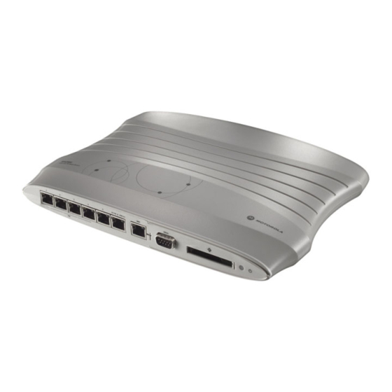
Product Overview 1.2 System Overview The WS2000 Wireless Switch provides a low-cost, feature-rich option for sites with one to six Access Ports. The WS2000 Wireless Switch works at the center of a network’s infrastructure to seamlessly and securely combine wireless LANs (WLANs) and wired networks. The switch sits on the network. Wireless Access Ports connect to one of the six available ports on the switch and the external wired network (WAN) connects to a single 10/100 Mbit/sec. -
Page 14: Hardware Overview
The four LAN ports with PoE have a third LED that indicates whether power is being delivered over the line to a power device (such as an Access Port). (See the WS2000 Wireless Switch LED explanation for more information on the meaning of the different state of the LEDs.) •... -
Page 15: Ws2000 Wireless Switch Led Functions
The switch has a large blue LED on the right front that indicates that the switch is powered on. Each port on the WS2000 Wireless Switch has either two or three LEDs that indicate the status of the port. Ports 1-4, which supply 802.3af Power over Ethernet (PoE), have three LEDs. The remaining two non-powered LAN ports and the WAN port have two LEDs. -
Page 16: Software Overview
1-6 WS2000 Wireless Switch System Reference Guide 1.4 Software Overview The WS2000 Wireless Switch software provides a fully integrated solution for managing every aspect of connecting Wireless LANs (WLANs) to a wired network, and includes the following components: 1.4.1 Operating System (OS) Services... - Page 17 2.1 Getting Started with the WS2000 Wireless Switch ....... . .
-
Page 18: Getting Started With The Ws2000 Wireless Switch
2.1 Getting Started with the WS2000 Wireless Switch This section provides just enough instruction to set up the WS2000 Wireless Switch, connect an Access Port, and test communications with a single mobile unit (MU) and the wide area network (WAN). The configuration suggestions made here are just the minimum needed to test the hardware. - Page 19 Getting Started NOTE: For optimum compatibility use Sun Microsystems’ JRE 1.4 or higher (available from Sun’s website), and be sure to disable Microsoft’s Java Virtual Machine if it is installed. The following screen displays. 4. Log in using admin as the User ID and symbol as the Password.
-
Page 20: Step 3: Set The Basic Switch Setting
7. Keep the Enable DNS Relay option checked. If not checked, clients on the LAN side of the WS2000 will not be able to use a DNS server to resolve URLs. 8. Click Apply to save changes. -
Page 21: Step 4: Configure The Lan Interface
Step 4: Configure the LAN Interface The first step of network configuration process is to figure out the topology of the LAN. The WS2000 Wireless Switch allows the administrator to enable and configure six different subnets. The administrator can assign an IP address, port associations, and DHCP settings for each subnet. -
Page 22: Step 5: Configure Subnet1
WLANs that are associated with the subnet. Step 5: Configure Subnet1 The WS2000 Network Management System allows the administrator to define and refine the configuration of the enabled subnets. Each of six subnets (short for “subnetworks”) can be configured as an identifiably separate part of the switch-managed local area network (LAN). -
Page 23: Step 6: Configure The Wan Interface
WAN port might connect to a larger corporate network. For a small business, the WAN port might connect to a DSL or a cable modem to access the Internet. The WS2000 Wireless Switch includes one WAN port. In order to set up communications with the outside world, select [Network Configuration] -->... -
Page 24: Setting Up Point-To-Point Over Ethernet (Pppoe) Communication
DSL router. All fields take standard IP addresses in the form xxx.xxx.xxx.xxx. • IP Address refers to the IP address that the outside world uses to address this WS2000 Wireless Switch. • Click the More IP Addresses button to specify additional static IP addresses for the switch. -
Page 25: Step 7: Enable Wireless Lans (Wlans)
Step 7: Enable Wireless LANs (WLANs) The WS2000 Wireless Switch works either in a wired or wireless environment; however, the power of the switch is associated with its support of wireless networks. In order to use the wireless features of the switch, the administrator needs to enable up to four wireless LANs (WLANs). -
Page 26: Step 8: Configure Wlan Security
2-10 WS2000 Wireless Switch System Reference Guide 2. Verify that Access Port 1 is shown in the Access Ports Adopted field to the right. If it is not, verify the connection between the switch and the Access Port. The current settings for the associated Subnet and adopted Access Ports are displayed on this screen;... -
Page 27: Setting The Authentication Method
The authentication method sets a challenge-response procedure for validating user credentials such as username, password, and sometimes secret-key information. The WS2000 Wireless Switch provides two methods for authenticating users: 802.1x EAP and Kerberos. The administrator can select between these two methods. -
Page 28: Step 9: Test Connectivity
Stats). If it does not appear on the MU Stats screen, recheck the network and WEP settings on the mobile device. 4. In the Web browser, enter a URL for a site (such as www.motorola.com) on the WAN. If the site does not appear, go to the WAN Stats screen ([Status &... - Page 29 LAN/Subnet Configuration 3.1 Enabling Subnets for the LAN Interface..............3-2 3.1.1 Defining Subnets.
-
Page 30: Enabling Subnets For The Lan Interface
3-2 WS2000 Wireless Switch System Reference Guide 3.1 Enabling Subnets for the LAN Interface Subnets are used to maximize the available network addresses and to logically separate the existing organizational network into smaller related networks. The WS 2000 Wireless Switch allows administrators to enable and configure six different subnets for each switch. -
Page 31: Configuring Subnets
3.2 Configuring Subnets The WS2000 Network Management System allows the administrator to define and refine the configuration of the enabled subnets. Each of the six subnets (short for “subnetworks”) can be configured as an identifiably separate part of the switch-managed Local Area Network (LAN). Each subnet can include some combination of assigned ports and associated Wireless LANs (WLANs). - Page 32 3-4 WS2000 Wireless Switch System Reference Guide 1. Change the Name of the subnet to use a descriptive name that indicates something about the subnet. The name can contain seven characters, including spaces and numbers. It will appear in the left menu under the LAN menu item.
-
Page 33: The Dhcp Configuration
LAN/Subnet Configuration 3.2.1 The DHCP Configuration DHCP is a protocol that includes mechanisms for IP address allocation and delivery of host-specific configuration parameters from a DHCP server to a host. Some of these parameters are IP address, network mask, and gateway. The switch includes internal DHCP server and client features, and the subnet’s interface can use either capability. - Page 34 3-6 WS2000 Wireless Switch System Reference Guide 2. If Dynamic DNS services are needed on the subnet, check the box labeled Enable Dynamic DNS. Enabling Dynamic DNS will allow domain name information to be updated when the IP address associated with that domain changes.
-
Page 35: Configuring Subnet Access
IP addresses for users, mobile units, and applications that may prefer or require such access. 3.3 Configuring Subnet Access The WS2000 Network Management System allows the administrator to set up access rules for subnet-to- subnet and subnet-to-WAN communication. These access rules control communication between subnets and the outside world (the WAN). -
Page 36: The Access Exception Area
3-8 WS2000 Wireless Switch System Reference Guide 3.3.2 The Access Exception Area In the lower half of the screen, the access is controlled by specific rules that control the protocols that are allowed or denied between the two subnets or the subnet and the WAN. All rules are added to the exception table. - Page 37 LAN/Subnet Configuration • Specify a Name to identify the new access rule. For example, this could be the name of a particular application. • Select a transport type from the Transport column’s pull-down menu. The available transports are: Transport Description This selection designates all of the protocols displayed in the table’s pull-down menu, as described below.
-
Page 38: Advanced Subnet Access Settings
3-10 WS2000 Wireless Switch System Reference Guide 3.4 Advanced Subnet Access Settings There can be situations in which the standard subnet access setting process is not specific enough for the needs of an organization. Instead, access or firewall rules need to be defined based upon destination and source IP addresses, transport types, and ports. - Page 39 3-11 LAN/Subnet Configuration 7. Move rules to a higher or lower precedence by clicking the Move Up Move Down buttons, as necessary. 8. When you have finished defining the Firewall Rules, click the Apply button to save changes. Use the following information to help set the Firewall Rule fields: •...
-
Page 40: Alg - Configuration
IP address or addresses. This is specifically required in scenarios where Motorola’s Airdefence WIPS Server and Motorola’s AP300s converted to sensors are deployed. Communication between Motorola’s Airdefence Server and sensor AP300s uses proprietary protocol and uses specific ports. -
Page 41: Bridge Configuration
3-13 LAN/Subnet Configuration To configure ALG exception rules: 1. Click the button. This creates a new row in the Firewall Rules table. For the new row, the source IP (Src IP) and destination IP (Dst IP) are set to zero. Double click on them to change the IP addresses. 2. - Page 42 A root bridge defines the mesh configuration. Motorola recommends assigning a Base Bridge AP with the lowest bridge priority so it becomes the root in the STP.
-
Page 43: Virtual Lan (Vlan) Configuration
3-15 LAN/Subnet Configuration 3.7 Virtual LAN (VLAN) Configuration A Virtual Local Area Network or VLAN is a switched network that has been segmented by function or application rather than by the traditional LAN segmentation which is based on physical location. VLANs allow a greater level of flexibility than a standard LAN, and enable changes to be made to the network infrastructure without physically disconnecting network equipment. -
Page 44: Configuring Ip Filtering
3-16 WS2000 Wireless Switch System Reference Guide 5. Enter a list of allowed VLANs between 1 and 4094 in the Allowed VLANs box. The VLANs in this list will be allowed access through the WAN port. When entering multiple VLAN IDs, separate each ID with a comma. - Page 45 3-17 LAN/Subnet Configuration Transport Description Transmission Control Protocol (TCP) is a set of rules used with Internet Protocol (IP) to send data as message units over the Internet. While IP handles the actual delivery of data, TCP keeps track of individual units of data called packets.
- Page 46 3-18 WS2000 Wireless Switch System Reference Guide Transport Description IGMP The Internet Group Management Protocol (IGMP) is used between IP hosts and their immediate neighbor multicast agents to support the creation of transient groups, the addition and deletion of members of a group, and the periodic confirmation of group membership. IGMP is an asymmetric protocol and is specified here from the point of view of a host, rather than a multicast agent.
-
Page 47: Url Filtering
IP address instead of the URL of the restricted website. In this scenario, the WS2000 performs a reverse DNS lookup for the IP address. The reply is received in the form of a URL and this URL is used to apply filtering rules. If the reverse DNS lookup does not return an URL, then this feature enables you to control access. - Page 48 3-20 WS2000 Wireless Switch System Reference Guide The URL Parameters screen contains four lists containing parameters used for URL filtering. There are four parameters: • White list – Use this list to provide access to specific websites. Websites in the white list are always allowed access.
-
Page 49: Port Configuration
Auto Negotiation mode, speed and duplex states too. When the Auto Negotiation is enabled, the WS2000 determines the best operating speed and the duplex states for each port. To disable this, select Disable from the Auto Negotiation drop-down list. - Page 50 3-22 WS2000 Wireless Switch System Reference Guide...
-
Page 51: Wan Configuration
4.2 Configuring the WS2000 Firewall ........ -
Page 52: Configuring The Wan Interface
DSL or cable modem to access the Internet. The administrator needs to enter the WAN configuration information. The WS2000 Wireless Switch includes one WAN port. In order to set up communications with the outside world, select [Network Configuration] -->... -
Page 53: Setting Up Point-To-Point Over Ethernet (Pppoe) Communication
DSL router). • The two DNS Server fields specify DNS addresses of servers that can translate domain names, such as www.motorola.com, into IP addresses that the network uses when passing information. The Secondary DNS Server acts as a backup to the... - Page 54 4-4 WS2000 Wireless Switch System Reference Guide 1. Check Enable in the PPP over Ethernet area to enable the PPPoE protocol for high-speed connections. 2. Enter the Username Password required for authentication. The username and password is for the switch’s router to use when connecting to the ISP. When the Internet session starts, the ISP authenticates the username.
-
Page 55: Configuring The Ws2000 Firewall
In WS 2000 Wireless Switch, the NAT timeout configuration is global for any TCP/IP packet going through the firewall. This configuration restricts the type of UDP or TCP applications that can be used with WS2000. -
Page 56: Configurable Firewall Filters
4-6 WS2000 Wireless Switch System Reference Guide Enter a default timeout value (in seconds) for the switch to use as the timeout value when no matching records are found in the NAT Timeout Table below. This is a global configuration for any TCP/IP packets going through firewall that don't match other values. -
Page 57: Enabling Netbios Alg
Configuring NetBIOS ALG access requires two steps. Most of the configuration for using NetBIOS must be performed on the client device on the WAN side. On the devices on the WAN side of WS2000, the following configuration must be performed. -
Page 58: Configuring The Application Layer Gateway (Alg)
4.2.5 Configuring the Application Layer Gateway (ALG) Use the Application Layer Gateway (ALG) to control how clients on the LAN side of the WS2000 accesses the WAN. 1. Navigate to the ALG - Configuration screen using [Network Configuration] -->... - Page 59 WAN Configuration appropriate one from the drop down. ‘none’ indicates that the source IP address is sent without modification. This field has no effect if is selected as the destination interface. 6. In the HTTP-ALG column, select Enable to allow the HTTP ALG check on traffic from the source IP to the Destination IP address.
-
Page 60: Configuring Intrusion Prevention System
4-10 WS2000 Wireless Switch System Reference Guide 4.3 Configuring Intrusion Prevention System IP networks are vulnerable to security breaches by attackers exploiting known bugs in installed softwares. These attacks can originate from any host on the network or from devices outside the network. These attacks can either be intentional or un-intentional. - Page 61 4-11 WAN Configuration 2. To enable IPS, select the Enable IPS check box. 3. To enable the different signature categories that IPS uses, check the appropriate check box in the Signature Categories group. When checked, the IPS checks for intrusion on that protocol. The following IPS signature categories are available.
- Page 62 4-12 WS2000 Wireless Switch System Reference Guide 5. Set the Protocol Anomaly Detection Parameters next. The following values have to be provided. SMTP Header Length Enter the SMTP header length in this field. MIME Header Length Enter the MIME header length in this field.
-
Page 63: Configuring Network Address Translation (Nat)
4-13 WAN Configuration 4.4 Configuring Network Address Translation (NAT) NAT provides the translation of an Internet Protocol (IP) address within one network to a different, known IP address within another network. One network is designated the private network, while the other is the public. - Page 64 4-14 WS2000 Wireless Switch System Reference Guide 4. If the NAT type is 1 to Many, the 1 to Many button in the adjacent Outbound Mappings field is active, allowing the administrator to specify address assignments for each subnet. If no translation should be done, none should be selected for the subnet.
-
Page 65: Configuring Static Routes
NAT screen to save changes. 4.5 Configuring Static Routes A router uses routing tables and protocols to forward data packets from one network to another. The WS2000 switch’s router manages traffic within the switch’s network, and directs traffic from the WAN to destinations on the switch-managed LAN. -
Page 66: Creating User Defined Routes
4-16 WS2000 Wireless Switch System Reference Guide Subnet 1 If Subnet 1 is enabled, sets it as the Default Gateway Interface for all unspecified routes. Subnet 2 If Subnet 2 is enabled, sets it as the Default Gateway Interface for all unspecified routes. - Page 67 4-17 WAN Configuration 1. Select the RIP Type from the pull-down menu to be one of the following values. No RIP Depending on the RIP Direction setting, the No RIP option partially or completely disal- lows the switch’s router from exchanging routing information with other routers. Routing information may not be appropriate to share, for example, if the switch manages a private LAN.
- Page 68 4-18 WS2000 Wireless Switch System Reference Guide 4. If the Simple authentication method is selected, specify a password of up to 15 alphanumeric characters in the Password (Simple Authentication) field. 5. If the authentication method is selected, fill in the...
-
Page 69: Configuring A Virtual Private Network (Vpn)
A diagram of a typical VPN situation is shown below, where there is a VPN tunnel created between two WS2000 switches across the WAN. The diagram shows the settings for both switches. The WS2000 Network Switch provides VPN technology with a variety of security and setup options. Select [Network Configuration] -->... -
Page 70: Creating A Vpn Tunnel
4-20 WS2000 Wireless Switch System Reference Guide Use the Auto Initiate Interval to set the interval when the status of all tunnels are checked. This is a global configuration which is common for all the tunnels and is valid only when Auto Initiate is enabled. Normally, when the tunnel’s life time gets over, its gets disconnected. -
Page 71: Setting Up Vpn Security
4-21 WAN Configuration 3. Select the subnet that will be the local end of the tunnel from the Local Subnet menu. 4. Specify the IP address to use for the local WAN (Local Wan IP), which should be one of the (up to) eight IP addresses specified in the WAN screen. - Page 72 4-22 WS2000 Wireless Switch System Reference Guide 3. Select the authentication and anti-replay method you wish to use for the tunnel from the Authentication menu. None Disables AH authentication and the rest of the fields in this area will not be active.
-
Page 73: Setting Up Automatic Key Exchange
4-23 WAN Configuration AES 128-bit This option selects the Advanced Encryption Standard algorithm in use with 128-bit (32- character hexadecimal) keys. AES 192-bit This option selects the Advanced Encryption Standard algorithm in use with 192-bit (48- character hexadecimal) keys. AES 256-bit This option selects the Advanced Encryption Standard algorithm in use with 256-bit (64- character hexadecimal) keys. - Page 74 4-24 WS2000 Wireless Switch System Reference Guide 3. Forward secrecy is a key-establishment protocol that guarantees that the discovery of a session key or a long-term private key will not compromise the keys of any other sessions. Select from the Perfect Forward Secrecy menu to enable this option.
-
Page 75: Setting Up Internet Key Exchange (Ike)
4-25 WAN Configuration 3DES This option selects the 3DES encryption algorithm, which requires 192-bit (48-character hexadecimal) keys. When creating keys for 3DES, the first 8 bytes cannot equal the sec- ond 8 bytes, and the second 8 bytes cannot equal the third 8 bytes. AES 128-bit This options selects the Advanced Encryption Standard algorithm in use with 128-bit (32-character hexadecimal) keys. - Page 76 Also, the authentication method cannot be negotiated if the initia- tor chooses to use public key encryption. 4. Select the type of ID to be used for the WS2000 end of the tunnel from the Local ID Type menu.
-
Page 77: Vpn: Frequently Asked Questions
4-27 WAN Configuration AES 128-bit This options selects the Advanced Encryption Standard algorithm in use with 128-bit (32-character hexadecimal) keys. AES 192-bit This options selects the Advanced Encryption Standard algorithm in use with 192-bit (48-character hexadecimal) keys. AES 256-bit This options selects the Advanced Encryption Standard algorithm in use with 256-bit (64-character hexadecimal) keys. - Page 78 4.6.6.2 Do I need to add any special routes on the WS2000 switch to get my VPN tunnel to work? No. Packets for VPN are tunneled directly to the Remote VPN gateway. As long as a route exists to the Remote VPN gateway, no other routes are required.
- Page 79 First of all, one end of a VPN tunnel must have a static IP address. Assuming the other end of your VPN tunnel has a static IP, here is how you configure your WS2000 switch to use a DHCP WAN address with VPN.
- Page 80 4.6.6.7 How can I setup the WS2000 switch to accept VPN tunnels from gateways that have a DHCP WAN address? To accept a VPN tunnel from a unknown (DHCP) address, the WS2000 Wireless Switch operates in what is called responder-only mode. That is, it cannot initiate the VPN connection. It can only wait for a VPN connection to come in.
-
Page 81: Configuring Content Filtering
Content filtering allows system administrators to block specific commands and URL extensions from going out through the WS2000 switch’s WAN port. This feature allows blocking up to 10 files or URL extensions and allows blocking of specific outbound HTTP, SMTP, and FTP requests. - Page 82 4-32 WS2000 Wireless Switch System Reference Guide SAML (Send and Mail) This command initiates a mail transaction where mail data is sent to one or more local mailboxes and remote terminals. RESET (Reset) This command cancels the current mail transaction and informs the recipient to discard any data sent during this transaction.
-
Page 83: Configuring Dyndns
WAN Configuration 4.8 Configuring DynDNS The WS2000 Wireless Switch provides support for using the DynDNS service. Dynamic DNS is a feature offered by www.dyndns.com which allows the mapping of domain names to dynamically assigned IP addresses. When the dynamically assigned IP address of a client changes that new IP address is sent to the DynDNS servers and traffic for the specified domain(s) is routed to the new IP address. - Page 84 4-34 WS2000 Wireless Switch System Reference Guide...
-
Page 85: Wireless Configuration
Wireless Configuration 5.1 Enabling Wireless LANs (WLANs) ..............5-3 5.1.1 WLAN Summary . - Page 86 5-2 WS2000 Wireless Switch System Reference Guide 5.10.1 Updating Sensor Configuration Dynamically ............5-40 5.11 Wireless Intrusion Detection System.
-
Page 87: Enabling Wireless Lans (Wlans)
Wireless Configuration 5.1 Enabling Wireless LANs (WLANs) The WS 2000 Wireless Switch works in either a wired or wireless environment; however, the power of the switch is associated with its support of wireless networks. To use the wireless features of the switch, the administrator needs to enable one, two, or three wireless LANs (WLANs). - Page 88 By default, all ports of WS2000 Wireless Switch go through the STP convergence states whenever configuration changes were made. In scenarios where, on a wired bridge port, the L2 switch to which this WS2000 was connected to had STP BPDU guard enabled, would cause the WS2000 to go offline. This was...
-
Page 89: Ap Adoption Configuration
So, if there was a configuration change, all the MUs got disassociated and remained so till the STP processing was complete. Moreover, by design, the radio ports on the WS2000 were deleted and re-created every time a configuration change was made. The would force STP convergence steps on the new radio port and delay MUs re-association. - Page 90 5-6 WS2000 Wireless Switch System Reference Guide 2. Specify the following fields: Field Description Start MAC This field contains the lowest value in a range of MAC addresses that will use this particular adoption criteria. To specify a single MAC address instead of a range, enter it in this field as well...
-
Page 91: Configuring Wireless Lans
Rename the WLAN in this field, if desired. Character spaces are allowed. This change affects several other screens and the interface will also change the name in the left menu tree. Motorola recommends the use of descriptive names for WLANs. -
Page 92: Configuring Wireless Lan Security
5-8 WS2000 Wireless Switch System Reference Guide 1. Check the Disallow MU to MU Communications box to enable a communication block between mobile units (MUs) using this WLAN. Such communication might be a security issue, for example, on a corporate network. Leave this check box unchecked (default setting) to allow MU-to-MU communications on this WLAN. -
Page 93: Selecting The Authentication Method
Wireless Configuration 5.3.1 Selecting the Authentication Method The authentication method sets a challenge-response procedure for validating user credentials such as username, password, and sometimes, secret-key information. The WS 2000 Wireless Switch provides two methods for authenticating users: 802.1x EAP and Kerberos. The administrator can select between these two methods. - Page 94 5-10 WS2000 Wireless Switch System Reference Guide 3. The administrator is required to specify the RADIUS Server Address of a primary RADIUS server for this type of authentication to work. Providing the IP address of a secondary server is optional. The secondary server acts as a failover server if the switch cannot successfully contact the primary server.
-
Page 95: Configuring Kerberos Authentication
5-11 Wireless Configuration 10.In the Max. Retries field, set the maximum number of retries for a client to successfully reauthenticate after failing to complete the EAP process. If the mobile unit fails the authentication process in specified number of retries, the switch will terminate the connection to the mobile unit. Advanced Settings 11.The MU Quiet Period... -
Page 96: Setting The Encryption Method
5-12 WS2000 Wireless Switch System Reference Guide 3. A realm name functions similar to a DNS domain name. In theory, the realm name is arbitrary; however, in practice, a Kerberos realm is typically named using an uppercase version of the DNS domain name that is associated with hosts in the realm. -
Page 97: Configuring Wpa/Wpa2-Tkip Encryption
The pass key can be any alphanumeric string. The switch, other proprietary routers, and Motorola cards in mobile units (MUs) use an algorithm to convert an ASCII string to the same hexadecimal number, but this conversion is not required for a wireless connection. -
Page 98: Configuring Wpa2-Ccmp (802.11I) Encryption
5-14 WS2000 Wireless Switch System Reference Guide 2. To use WPA/WPA2-TKIP encryption with 802.1x EAP authentication or the No Authentication selection, click the WPA/WPA2-TKIP Settings button to display a sub-screen for key and key rotation settings. 3. To Enable WPA2 check the Use WPA2 check box to use WPA2 encryption in conjunction with WPA-TKIP. - Page 99 Access Port to carry out an 802.1x authentication with another Access Port before it roams over to it. The WS2000 switch will cache the keying information of the client until it roams to the new Access Port. This enables the roaming the client to start sending and receiving data sooner by not having to do 802.1x authentication after it roams.
-
Page 100: Keyguard
The pass key can be any alphanumeric string. The switch, other proprietary routers, and Motorola cards in mobile units (MUs) use an algorithm to convert an ASCII string to the same hexadecimal number, but this conversion is not required for a wireless connection. -
Page 101: Mobile Unit Access Control List (Acl)
5-17 Wireless Configuration To configure IP Filtering for the WLAN: 1. Check the box marked Enable IP Filtering to turn on IP Address based filtering for inbound and outbound traffic on the WLAN. 2. Click the IP Filtering button to display a sub-screen for filtering settings on the WLAN. 3. -
Page 102: Configuring Access Ports
5-18 WS2000 Wireless Switch System Reference Guide 3. Each entry in the table specifies one or more MAC address to be used to match with a mobile unit’s MAC address that is attempting to gain access to the WLAN. Specify a single address (by specifying... - Page 103 5-19 Wireless Configuration The switch creates a default name for a newly found switch consisting of “AP” and a unique number. During this detection process, the switch collects the following information from the Access Port: MAC address Each Access Port has a unique Media Access Control (MAC) address by which it is identified. This address is burned into the ROM of the Access Port.
- Page 104 5-20 WS2000 Wireless Switch System Reference Guide The following screen is displayed with the settings for the selected Access Port. 3. From this screen, the administrator can change several pieces of information about each Access Port. Name Administrators can change the names of the Access Ports from Access Port# to something much more descriptive, so that they can easily identify which Access Port is being referenced in the various screens and in the left menu.
-
Page 105: Setting Default Access Port Settings
5.5 Setting Default Access Port Settings The WS2000 Network Switch can support up to six Access Port. These Access Ports can be either a 802.11a or 802.11b radio type. When an Access Port associates with the wireless switch, the initial settings for that Access Port are taken from the Default Access Port Setting for the appropriate radio type. -
Page 106: Common Settings To All Radio Types
NOTE: With this mode, channel can not be manually selected. Automatic Mode (Automatic Channel Selection) Select this radio button to enable Automatic Channel Selection (ACS) feature of WS2000/ AP300. With this mode, the AP will scan the available channels and select the one in which least number of beacons is heard. - Page 107 5-23 Wireless Configuration Antenna Use the drop-down menu to configure the Antenna Diversity settings for Access Ports that use Diversity external antennas. Full Diversity: Utilizes both antennas to provide antenna diversity Primary Only: Enables only the primary antenna Secondary Only: Enables only the secondary antenna NOTE: Antenna Diversity should only be enabled if the Access Port has two matching external antennas.
-
Page 108: Radio-Specific Settings
5-24 WS2000 Wireless Switch System Reference Guide Beacon Set the Access Port beacon settings by Settings clicking on the Beacon Settings button. Set the following beacon values. Beacon Interval—A beacon is a packet broadcast by the adopted Access Ports to keep the network synchronized. -
Page 109: Advanced Access Port Settings
5-25 Wireless Configuration Support Short Check the Support Short Preamble box to allow the Access Port to communicate with Preamble the MUs using a short 56-bit preamble. A preamble is the beginning part of a frame. The preamble comprises such elements as robust carrier sensing, collision detection, equalizer training, timing recovery, and gain adjustment. -
Page 110: Radio Settings
Access Port and the MUs. MU dB Power This is a Motorola specific feature. This value indicates the amount of power in dBm that the Level MU should reduce its Tx power by with respect to the Tx power of the AP. This feature is used Adjustment to reduce the amount of radio noise in the environment for better reception. -
Page 111: Antenna Settings
5-27 Wireless Configuration Channel Click the Channel Selection Mode button to open a sub-screen where you can select the Selection modes by which channels are selected. The available options are User Selection, Uniform Mode Spreading, and Automatic Selection. Selecting Automatic Selection from the sub-screen enables the Remap Channel button and... - Page 112 5-28 WS2000 Wireless Switch System Reference Guide RTS Threshold Set the Request to Send Threshold (RTS Threshold) by specifying a number. RTS is a transmitting station’s signal that requests a Clear To Send (CTS) response from a receiving station. This RTS/CTS procedure clears the air when many mobile units (MUs) are contending for transmission time.
-
Page 113: Quality Of Service Configuration
5-29 Wireless Configuration Beacon Settings Set the Access Port beacon settings by clicking Beacon Settings button. Beacon Interval A beacon is a packet broadcast by the adopted Access Ports to keep the network synchronized. Included in a beacon is information such as the WLAN service area, the access-port address, the broadcast destination addresses, a time stamp, and indicators about traffic and delivery such as a... -
Page 114: Setting The Bandwidth Share Mode
5-30 WS2000 Wireless Switch System Reference Guide 5.7.1 Setting the Bandwidth Share Mode First, specify how the networking resources will be shared. The Bandwidth Share Mode provides three allocation options: Packets are served on a first-come-first-served basis. If this option is selected, the... -
Page 115: Configuring Voice Prioritization And Multicast Address Settings
5-31 Wireless Configuration Bandwidth Share for Each WLAN Table The fields in this table are: WLAN Name This field lists the WLANs on the switch by name (the same name that you see in the left menu). You cannot change the name of the WLAN in this field. Go to the Wireless screen to change a WLAN name. -
Page 116: Rogue Access Point (Port) Detection
5-32 WS2000 Wireless Switch System Reference Guide To set up Port Authentication for all adopted AP300 Access Ports: 1. In the Username field, specify a 802.1x username for all AP300 Access Ports adopted by the switch. To use the default username click the <- Default... -
Page 117: Setting Up The Detection Method
5-33 Wireless Configuration The Rogue AP Detection screen allows the administrator to determine how thoroughly the switch will search for rogue APs as well as list the approved APs. 5.9.1 Setting Up the Detection Method The WS 2000 Wireless Switch provides three methods for detecting rogue Access Points (APs). Use the top part of the Rogue AP Detection screen to set the method or methods that the switch will use to detect rogue APs. -
Page 118: Defining And Maintaining Approved Ap List Rules
5-34 WS2000 Wireless Switch System Reference Guide NOTE: Note that only some access ports have the capability of being a Detector AP, including Motorola AP 100, AP 200, and AP 300 Access Ports. 5. In the Scan Interval field, enter a time interval (in minutes) between detection RF scans. Do this for each of the selected detection methods. -
Page 119: Examine The Approve And Rogue Access Ports
5-35 Wireless Configuration 5.9.3 Examine the Approve and Rogue Access Ports This screen displays information about APs known to the switch. All approved APs are listed in the upper table. All rogue APs are listed in the lower table. This screen also allows the administrator to create detection rules from the information collected about approved or rogue APs. - Page 120 5-36 WS2000 Wireless Switch System Reference Guide First Seen This field indicates the number of elapsed hours since the rogue AP was first noticed on the network in hours:minutes:seconds. Last Seen This field indicates the number of elapsed hours since the rogue AP was last noticed on the network in hours:minutes:seconds.
- Page 121 5-37 Wireless Configuration To enable and configure Rogue AP Containment: 1. Check the Enable Rogue AP Containment box to enable this feature. 2. All MUs associated to Rogue APs in the Rogue AP Containment list are deauthenticated by the switch. Deauth Interval value sets the time duration in seconds between two such de-authentications.
-
Page 122: Setting Snmp Traps For Rogue Aps
5-38 WS2000 Wireless Switch System Reference Guide Details About the Rogue Detector The lower portion of the Rogue AP Detail screen displays information about the AP that detected the rogue. This information if provided to the administrator to help located the rogue. -
Page 123: Configuring Wireless Intrusion Protection System (Wips)
Denial of Service (DoS) attacks. It is also able to actively suppress any rogue clients and APs in the network. Motorola’s WIPS solution utilizes AP300s that act as dedicated sensors and send out relevant information to a centralized WIPS server. The WIPS server correlates all the data and provides threat mitigation services. -
Page 124: Updating Sensor Configuration Dynamically
5-40 WS2000 Wireless Switch System Reference Guide 5.10.1 Updating Sensor Configuration Dynamically To update the configuration of AP300s acting as sensors, the following CLI command is available. update Sends the configuration file to a sensor. Sensor configuration information is not stored in the switch configuration. -
Page 125: Wireless Intrusion Detection System
The Motorola Wireless Intrusion Detection System (WIDS) protects against a wide range of malicious attacks on the WS2000 Wireless Switch. This feature inspects each packet that is received by the WS2000 and then based on analysis decides if an intrusion is happening on the device. -
Page 126: Wids Configuration
5-42 WS2000 Wireless Switch System Reference Guide WIDS also keep track of anomalies. An anomaly is defined as an event which is different from the general occurrences on a WS2000. The following anomalies are tracked: • null-dst - NULL destination •... -
Page 127: Filtered Mus
5-43 Wireless Configuration 5.11.2 Filtered MUs The Filtered MUs screen displays a list of all MUs that have been filtered out by WIDS. You can, if required, remove any or all MUs listed in the Filtered MUs table. The Filtered MUs table displays the following: MU MAC The MAC address of the MU that has been filtered out. -
Page 128: Smart Scan
5-44 WS2000 Wireless Switch System Reference Guide 5.12 Smart Scan Each radio, depending on the country of operation, provides a large number of channels for data transmission. This means that when a MU roams from one AP to another, it has to scan all available channels for that radio to find the WLAN it was connected to. -
Page 129: Self Heal
A self-healing network is one that is capable of maintaining the availability of the network under all circumstances. The network can self-manage in response to the events that occur within the network. Self heal for WS2000 is provided by the device maintaining a Neighbor Table with entries for each device in its neighborhood. -
Page 130: Mesh Settings
Mesh network is supported by the WS2000 Wireless Switch through APs that have mesh network support integrated in them. AP300 from Motorola is a thin AP that has in built support for Mesh networks. When a WS2000 is configured for Mesh support, it uses AP300s that have been adopted as base bridges or client bridges to establish mesh networks. -
Page 131: Mesh Base Setting
5-47 Wireless Configuration NOTE: A radio can act as a Mesh Base or as a Mesh Client or as both. 5.14.1 Mesh Base Setting Use the Mesh Base Settings area of the Mess Setting screen to set up the device as a Mesh Base device. To do so: 1. - Page 132 5-48 WS2000 Wireless Switch System Reference Guide...
- Page 133 Administrator and User Access 6.1 Configuring Administrator Access ..............6-2 6.1.1 Selecting the Type of Admin Access .
-
Page 134: Configuring Administrator Access
“admin” and the initial password is “symbol”. The WS2000 Access screen is used to configure the access to the WS 2000 Wireless Switch. This screen is used to configure the access and related parameters for the WS 2000 Wireless Switch. You can also change the administrative password from this screen. - Page 135 Subnets 1-6 Columns Use the Subnets 1 - 6 columns to allow access to the WS2000 Wireless Switch from the available subnets. When not selected, administrative access to the WS2000 is not available for that protocol from that subnet.
-
Page 136: Configuring Secure Shell Connection Parameters
WS2000 Certificate drop down list to select the security certificate to use for accessing the WS2000 Wireless Switch. The ‘default’ certificate is used by default. To use other certificates, it must be installed on the WS2000 before it can be used. -
Page 137: Http(S) Server Parameters
The sub- screen will close and the focus is returned to the WS2000 Access screen. NOTE: If the administrative login password is lost or forgotten, please contact Motorola Technical Support for instructions on how to resolve the issue. 6.2 Configuring User Authentication The WS 2000 Wireless Switch provides an integrated RADIUS server as well as the ability to work with external RADIUS and LDAP servers to provide user database information and user authentication. -
Page 138: Configuring The Radius Server
6-6 WS2000 Wireless Switch System Reference Guide 6.2.1 Configuring the RADIUS Server The WS 2000 Wireless Switch provides an integrated RADIUS server as well as the ability to work with external RADIUS and LDAP servers to provide user database information and authentication. The RADIUS Server page allows the admin to set up data sources, as well as specify authentication information for the built-in RADIUS server. - Page 139 7. DH Param File is required to support Cipher Suite v 0x13 (TLS_DHE_DSS_WITH_3DES_EDE_CBC_SHA) for EAP-TLS/TTLS. If this file does not exist on a WS2000, it is automatically created when the device is booted up. Use Create DH Param File to create the file as and when required.
-
Page 140: Configuring Lightweight Directory Access Protocol (Ldap) Authentication
6-8 WS2000 Wireless Switch System Reference Guide 6.2.2 Configuring Lightweight Directory Access Protocol (LDAP) Authentication When the RADIUS Data Source is set to use an external LDAP server (see Configuring the RADIUS Server), the LDAP screen is used to provide information about the external LDAP server. Select... -
Page 141: Setting Up A Proxy Radius Server
Administrator and User Access Group Member Attribute Specify the Group Member Attribute to be sent to the LDAP server when authenticating the users. The following are the additional settings that are required for the LDAPS data source. Fully Qualified Domain name Enter the fully qualified domain name of the LDAP server that provides authentication information to your RADIUS server. -
Page 142: Managing The User Database
6-10 WS2000 Wireless Switch System Reference Guide Port Enter the TCP/IP port number for the RADIUS server that will be acting as a proxy server. The default port is 1812. Shared Secret Set a shared secret to be used for each suffix that will be used for authentication with the RADIUS proxy server. - Page 143 6-11 Administrator and User Access 6.2.4.1 Adding Groups This Groups table displays a list of all groups in the local RADIUS server's database. The groups are listed in the order that they are added. Although groups can be added and deleted, there is no capability currently to edit the name of a group.
-
Page 144: Adding New Guest Users Quickly
6-12 WS2000 Wireless Switch System Reference Guide 6.2.5 Adding New Guest Users Quickly The WS2000 also enables the administrators to add a guest user quickly. A separate screen is provided outside of the normal administrative environment for this purpose. To add a new guest user quickly: 1. - Page 145 6-13 Administrator and User Access NOTE: Before this screen is used to create a guest user, there must be at least one guest user group configured on the switch.To create a guest user group, see section Adding Groups. To create a guest user: 1.
-
Page 146: Setting The User Access Policy
6-14 WS2000 Wireless Switch System Reference Guide 3. Click Print. The user information is printed. You can then provide this information to the user for reference. 6.2.6 Setting the User Access Policy The RADIUS Access Policy screen allows you to set WLAN access based on a user group defined on the User Database screen. - Page 147 6-15 Administrator and User Access Each Group ID defined in the User Database screen appears on the Access Policy screen as a single row in the table. Each wireless LAN represents a column in the table. 1. To enable group access to a particular WLAN, check the box for that WLAN in the row corresponding to the group.
-
Page 148: Managing Digital Certificates
The WS2000 Management System provides the means to import and maintain a set of CA certificates to be used as an authentication option for VPN access. To use the certificate for a VPN tunnel, define a tunnel and select the IKE settings to use either RSA or DES certificates. - Page 149 6-17 Administrator and User Access To import a CA certificate perform the following steps: 1. Select [System Configuration] --> [Certificate Mgmt] --> CA Certificates from the left menu. The following screen appears. 2. Copy the content of the CA Certificate message into the clipboard and then click Paste from Clipboard.
-
Page 150: Creating Self Certificates
6-18 WS2000 Wireless Switch System Reference Guide 6.3.2 Creating Self Certificates Self certificates are those for which the organization creates a certificate request, sends it off to a Certificate Authority (CA) to be signed, and then imports the signed certificate into the management system. To go... - Page 151 6-19 Administrator and User Access Signature Indicate the signature algorithm to use for the certificate. The selection should match the Algorithm VPN tunnel settings. • MD5-RSA: Message Digest 5 algorithm in combination with RSA encryption. • SHA1-RSA: Secure Hash Algorithm 1 in combination with RSA encryption. Key Length Indicate the desired length of the key.
- Page 152 6-20 WS2000 Wireless Switch System Reference Guide...
-
Page 153: Switch Administration
7.4 Changing the Location and Country Settings of the WS2000 ....... -
Page 154: Overview Of Administration Support
7-2 WS2000 Wireless Switch System Reference Guide 7.1 Overview of Administration Support The WS2000 Network Management System provides several screens for administering the switch and monitoring activity on the switch. From the interface the administrator can: • Change the general system settings, such as the name of the switch and the location of the switch •... -
Page 155: Changing The Name Of The Switch
7.3 Changing the Name of the Switch When the administrator first logs into the WS2000 Network Management System, the System Settings screen appears. One of the fields in this screen is the System Name field. In this field, the administrator can specify the name of the switch. -
Page 156: Configuring The Dns Server Information
7-4 WS2000 Wireless Switch System Reference Guide 1. Select [System Configuration] --> System Settings from the left menu. 2. Type in a description of the physical location of the switch within your facility into the Location field. 3. Find the Country field and use the drop down menu to select the correct country from the list. -
Page 157: Configuring The Domain Name For The Switch
7.6 Configuring the Domain Name for the switch Domain Name field provides domain information for reverse DNS queries. The name of the WS2000 as entered in the System Name field and the device’s domain name as entered in the... -
Page 158: Configuring Switch Redundancy
This is the default setting. Redundancy Two WS2000 switches are connected, with one set as a primary and the other as a standby. The primary switch will send heartbeat packets to the specified port of the standby switch at a specified interval. -
Page 159: Redundancy Operations Status
WS2000 Wireless Switch. 4. Compare the WS2000 Version value with the most recent version listed on the site. All updates will be listed along with a description of what the update contains. 5. Check to see if an administrator has already downloaded the file. It might already be on an FTP server at... -
Page 160: Performing The Firmware Update
When a partition is selected as the active partition, the new firmware will be installed in that partition on the CF card. This enables the CF card to host 2 different WS2000 firmware images in addition to the one present in the onboard flash of the switch. -
Page 161: Formatting A Compact Flash Card
FTP. 3. For firmware upgrade to work, a CF card must be inserted in the WS2000’s CF card slot. Also, the CF card must have atleast 64 MB of free space. When SFTP is used to upgrade the firmware, the firmware image is first downloaded to the CF card. -
Page 162: Limitation Of File System On The Compact Flash Card
WARNING! Sometimes you might encounter an issue with mounting CF cards that have been formatted on a Windows/XP machine. To resolve this issue, reset the WS2000 with the CF card inserted. Go to the boot prompt. From the boot prompt enter the following... - Page 163 The external DHCP server which handles the DHCP client needs to be configured with this option to provide TFTP/FTP server IP, firmware file name and config file to facilitate WS2000 for Auto FW/Config upgrade. Any string provided in the text field will be prefixed with a “SymbolWS.WS2K”...
-
Page 164: Exporting And Importing Wireless Switch Settings
7.9 Exporting and Importing Wireless Switch Settings All of the configuration settings for the WS2000 Wireless Switch can be saved to a configuration file and then either imported back into the same switch or transferred to another switch. This file-based configuration saving feature provides several benefits: •... - Page 165 Export. Export/Import configuration settings using HTTP To import configuration settings using HTTP, you have to first upload a configuration file to the WS2000 and then apply it. Similarly, to export a WS2000’s configuration setting, you have to first generate the configuration file and then download it to your PC.
- Page 166 7-14 WS2000 Wireless Switch System Reference Guide 3. Enter the administrative password for this WS2000 in the Administrator Password field. This allows you to download the configuration file from the WS2000. 4. Click File. The Opening cfg,txt dialog displays. If you want to view the downloaded file, click Open with option to select it.
-
Page 167: Updating Sensor Firmware
Switch Administration 7.10 Updating Sensor Firmware WS2000 provides support for setting up AP300s as dedicated sensors. This feature enables updating the firmware for these APs without disturbing the switch settings. The following must be noted with respect to sensor firmware update: •... -
Page 168: Updating The Sensor Firmware
SNMP allows an administrator to manage network performance, find and solve network problems, and plan for network growth. The WS2000 Wireless Switch includes SNMP management functions for gathering information from its network components, and communicating that information to specific users. -
Page 169: Setting The Snmp Version Configuration
7-17 Switch Administration Select [System Configuration] --> SNMP Access from the left menu to set up SNMP service. 7.11.1 Setting the SNMP Version Configuration The SNMP Access screen allows the administrator to define SNMP v1/v2c community definitions and SNMP v3 user definitions. SNMP v1 and v2c provide a strong network management system, but their security is relatively weak. - Page 170 7-18 WS2000 Wireless Switch System Reference Guide 7.11.1.2 Setting Up SNMP v3 Community Definitions Setting up the v3 user definition is very similar to the v1/v2c community definitions. The difference is the addition of a user security level and a user password.
-
Page 171: Setting Up The Access Control List
7-19 Switch Administration 7.11.2 Setting Up the Access Control List To set up the Access Control list as specified by a range of IP addresses, click the SNMP Access Control button at the bottom of the SNMP Access screen. The SNMP Access Control screen appears: 1. -
Page 172: Setting The Trap Configuration For Snmp V3
7-20 WS2000 Wireless Switch System Reference Guide 3. Specify a destination User Datagram Protocol (UDP) port for receiving the traps that are sent by SNMP agents. UDP offers direct connection for sending and receiving datagrams over an IP network. 4. Specify a... - Page 173 Network Physical port status The status changes for one of the ports on the front of the WS2000, such Traps change as if a device is plugged into or unplugged from the switch, or if the link is lost between the switch and the connected device.
- Page 174 7-22 WS2000 Wireless Switch System Reference Guide Trap Trap Name Generates a Trap whenever… Category IPS Event An Intrusion Prevention System event is detected by the switch’s firewall. IPS Event traps are sent until the attack stops. These traps are internally rate-limited to prevent flooding of traps in case of heavy attack traffic on the network.
-
Page 175: Setting Rf Traps
7-23 Switch Administration 3. Click the Apply button to save the trap settings. 4. It is necessary to tell the switch where to send the notifications. Make sure to set the trap configuration to indicate where to send the trap notifications. 7.11.7 Setting RF Traps A screen is also available to specify traps caused when certain rates of activities either exceed or drop below a specified threshold. -
Page 176: Specifying A Network Time Protocol (Ntp) Server
7-24 WS2000 Wireless Switch System Reference Guide Average Retries The maximum threshold for the average number of retries for each of the devices before a trap is sent. % Gave Up The maximum threshold for the total percentage of packets that are given up for each of the devices before a trap is sent. - Page 177 7-25 Switch Administration NOTE: When NTP is enabled on the WS2000, you will not be able to set time manually. 4. To enable time service on the switch, check the Enable NTP on check box and continue with the rest of the steps below.
-
Page 178: Setting Up And Viewing The System Log
7.13 Setting Up and Viewing the System Log The WS2000 Network Management System keeps a log of the events that happen on the switch. The switch has a modest of amount of memory to store events. If the administrator wishes to keep a more complete event history, the administrator needs to enable a log server. -
Page 179: Commands To Unmount A Cf Card
–h /mnt/cf 7.15 Sample Configuration File All the configuration settings for the WS2000 Wireless Switch can be saved to a configuration file and then either imported back into the same switch or transferred to other switches. Below is a sample configuration file that has been annotated using comment lines. All comment lines begin with // and are blue in color. - Page 180 7-28 WS2000 Wireless Switch System Reference Guide set airbeam mode disable set airbeam enc-passwd a11e00942773 set applet lan enable set applet lan any-nw enable set applet lan 1 enable set applet lan 2 enable set applet lan 3 enable set applet lan 4 enable...
- Page 181 7-29 Switch Administration set ssh lan any-nw enable set ssh lan 1 enable set ssh lan 2 enable set ssh lan 3 enable set ssh lan 4 enable set ssh lan 5 enable set ssh lan 6 enable set ssh wan enable set timeout 0 set airbeam logging disable set ftp wan logging disable...
- Page 182 7-30 WS2000 Wireless Switch System Reference Guide system logs // Logs menu set mode disable set level L6 set cf_logging_mode disable system // NTP menu set mode disable set server 1 \0 set server 2 \0 set server 3 \0...
- Page 183 7-31 Switch Administration set ap-denied-adopt disable set ap-radar disable set cf-thresh 1024 set min-pkt 1000 set dos-rate-limit 10 set rate pkts switch 0.00 set rate pkts wlan 0.00 set rate pkts ap 0.00 set rate pkts mu 0.00 set rate mbps switch 0.00 set rate mbps wlan 0.00 set rate mbps ap 0.00 set rate mbps mu 0.00...
- Page 184 7-32 WS2000 Wireless Switch System Reference Guide set inactive-timeout 120 system authentication set mode local set auth-loc radius system authentication radius // AUTHENTICATION RADIUS configuration set auth-server-ip 192.168.0.4 set auth-server-port 1812 set enc-shared-secret a11e00942773 system userdb user // clear userdb user configuration...
- Page 185 7-33 Switch Administration system radius ttls // radius EAP TTLS configuration set auth pap system radius policy // radius access policy configuration system radius ldap // radius LDAP configuration set domain \0 set port 389 set binddn cn=Manager,o=mobion set basedn o=mobion set login (uid=%{Stripped-User-Name:-%{User-Name}}) set pass_attr userPassword set groupname cn...
- Page 186 7-34 WS2000 Wireless Switch System Reference Guide http // system http configuration import self default network wlan // WLAN 1 configuration set mode 1 enable set ess 1 101 set enc 1 none set auth 1 none set wep-mcm index 1 1...
- Page 187 7-35 Switch Administration set ccmp enc-key 1 c2767fe55c0a564fa8cd3201b1984a33f986e7872572740a80c6dcff32905735 set ccmp interval 1 86400 set ccmp rotate-mode 1 disable set ccmp mixed-mode 1 disable set ccmp preauth 1 disable set ccmp opp-pmk 1 enable set name 1 WLAN1 set no-mu-mu 1 disable set vop 1 enable set bcast 1 disable set adopt 1 allow...
- Page 188 7-36 WS2000 Wireless Switch System Reference Guide set eap adv mu-tx 2 5 set eap adv mu-timeout 2 10 set eap adv mu-retry 2 2 set eap adv server-timeout 2 5 set eap adv server-retry 2 2 set eap rad-acct mode 2 disable...
- Page 189 7-37 Switch Administration set wep-mcm enc-key 3 1 c2767fe55c0a564f90f50a3989 set wep-mcm enc-key 3 2 f2464fd56c3a667fa0c53a09b9 set wep-mcm enc-key 3 3 e2565fc57c2a766fb0d52a19a9 set wep-mcm enc-key 3 4 92262fb50c5a061fc0a55a69d9 set mu-inact 10 set kerb user 3 \0 set kerb realm 3 \0 set kerb port 3 1 88 set kerb port 3 2 88 set kerb port 3 3 88...
- Page 190 7-38 WS2000 Wireless Switch System Reference Guide set acl 3 allow set mcast 3 1 01005E000000 set mcast 3 2 09000E000000 set eap syslog mode 3 disable set vlan-id 3 3 set secure-beacon 3 disable set eap rad-bind-interface 3 1 none...
- Page 191 7-39 Switch Administration set tkip interval 4 86400 set tkip rotate-mode 4 disable set tkip wpa2 4 disable set tkip preauth 4 disable set tkip pmk 4 enable set ccmp type 4 phrase set ccmp enc-phrase 4 a11e00942773343deb84 set ccmp enc-key 4 c2767fe55c0a564fa8cd3201b1984a33f986e7872572740a80c6dcff32905735 set ccmp interval 4 86400 set ccmp rotate-mode 4 disable...
- Page 192 7-40 WS2000 Wireless Switch System Reference Guide set eap port 5 2 1812 set eap reauth mode 5 disable set eap reauth retry 5 2 set eap reauth period 5 3600 set eap adv mu-quiet 5 10 set eap adv mu-tx 5 5...
- Page 193 7-41 Switch Administration delete 5 all // WLAN 6 configuration set mode 6 disable set ess 6 106 set enc 6 none set auth 6 none set wep-mcm index 6 1 set wep-mcm enc-key 6 1 c2767fe55c0a564f90f50a3989 set wep-mcm enc-key 6 2 f2464fd56c3a667fa0c53a09b9 set wep-mcm enc-key 6 3 e2565fc57c2a766fb0d52a19a9 set wep-mcm enc-key 6 4 92262fb50c5a061fc0a55a69d9 set mu-inact 10...
- Page 194 7-42 WS2000 Wireless Switch System Reference Guide set ccmp preauth 6 disable set ccmp opp-pmk 6 enable set name 6 WLAN6 set no-mu-mu 6 disable set vop 6 enable set bcast 6 disable set adopt 6 allow set acl 6 allow...
- Page 195 7-43 Switch Administration set eap rad-acct mode 7 disable set eap rad-acct timeout 7 10 set eap rad-acct retry-count 7 2 set tkip type 7 phrase set tkip enc-phrase 7 a11e00942773343deb84 set tkip enc-key 7 c2767fe55c0a564fa8cd3201b1984a33f986e7872572740a80c6dcff32905735 set tkip interval 7 86400 set tkip rotate-mode 7 disable set tkip wpa2 7 disable set tkip preauth 7 disable...
- Page 196 7-44 WS2000 Wireless Switch System Reference Guide set kerb user 8 \0 set kerb realm 8 \0 set kerb port 8 1 88 set kerb port 8 2 88 set kerb port 8 3 88 set eap port 8 1 1812...
- Page 197 7-45 Switch Administration set secure-beacon 8 disable set eap rad-bind-interface 8 1 none set eap rad-bind-interface 8 2 none set handshake-timeout 8 2000 set handshake-retry-count 8 3 set enforce-pmk-validation enable set wireless-stp enable delete 8 all set wep_shared disable // Rogue AP Scan configuration network wlan rogueap...
- Page 198 7-46 WS2000 Wireless Switch System Reference Guide set dtim 802.11a 3 10 set dtim 802.11a 4 10 // Default 802.11b radio configuration set reg 802.11b in/out 1 20 set rate 802.11b 1,2 1,2,5.5,11 set div 802.11b full set ch_mode 802.11b fixed set beacon intvl 802.11b 100...
- Page 199 7-47 Switch Administration // copydefaults 9 // copydefaults 10 // copydefaults 11 // copydefaults 12 // Individual AP settings exported for, static AP configuration forget all set sip_cac_mode disable set force-l3 disable denyap // AP Deny List menu delete all // Self-Healing configuration network selfheal...
- Page 200 7-48 WS2000 Wireless Switch System Reference Guide del all all network smartscan // smartscan configuration delete 11a delete 11bg // Access Port Mesh configuration network mesh set client 1 disable set wlan 1 1 set auto 1 enable del 1 all...
- Page 201 7-49 Switch Administration del 6 all set base 6 disable set max-clients 6 6 set client 7 disable set wlan 7 1 set auto 7 enable del 7 all set base 7 disable set max-clients 7 6 set client 8 disable set wlan 8 1 set auto 8 enable del 8 all...
- Page 202 7-50 WS2000 Wireless Switch System Reference Guide set ipadr 2 192.168.1.1 set mask 2 255.255.255.0 set dgw 2 192.168.1.1 set mode 3 enable set name 3 Subnet3 set ipadr 3 192.168.2.1 set mask 3 255.255.255.0 set dgw 3 192.168.2.1 set mode 4 enable set name 4 Subnet4 set ipadr 4 192.168.3.1...
- Page 203 7-51 Switch Administration set wins 1 192.168.0.254 set lease 1 86400 set domain 1 \0 set fwdzone 1 \0 set tftp-server 1 0.0.0.0 set bootfile 1 \0 set option-189 1 \0 set option-43 1 \0 set mode 1 server set range 1 192.168.0.100 192.168.0.254 set mode 2 server set ddnsmode 2 disable set ddnsusrcls 2 single...
- Page 204 7-52 WS2000 Wireless Switch System Reference Guide set domain 4 \0 set fwdzone 4 \0 set tftp-server 4 0.0.0.0 set bootfile 4 \0 set option-189 4 \0 set option-43 4 \0 set mode 4 server set range 4 192.168.3.100 192.168.3.254...
- Page 205 7-53 Switch Administration bridge set priority 1 32768 set hello 1 2 set msgage 1 20 set fwddelay 1 15 set ageout 1 300 set wireless-trunking 1 disable set priority 2 32768 set hello 2 2 set msgage 2 20 set fwddelay 2 15 set ageout 2 300 set wireless-trunking 2 disable...
- Page 206 7-54 WS2000 Wireless Switch System Reference Guide port // LAN Port configuration set auto-negotiation port1 enable set speed port1 100M set duplex port1 full set auto-negotiation port2 enable set speed port2 100M set duplex port2 full set auto-negotiation port3 enable...
- Page 207 7-55 Switch Administration set revertdelay 5 set preempt enable set op_state standalone // WAN configuration network set dhcp enable set mask 255.255.255.0 set pppoe mode disable set pppoe user \0 set pppoe idle 600 set pppoe ka disable set pppoe type pap/chap set pppoe mss 1452 set mode 1 enable set mode 2 disable...
- Page 208 7-56 WS2000 Wireless Switch System Reference Guide set outb map s4 1 set outb map s5 1 set outb map s6 1 // Inbound NAT configuration delete inb 1 all delete inb 2 all delete inb 3 all delete inb 4 all...
- Page 209 7-57 Switch Administration set override disable submap // Subnet map configuration set default s1 w allow set default s1 s2 allow set default s1 s3 allow set default s1 s4 allow set default s1 s5 allow set default s1 s6 allow set default s2 w allow set default s2 s1 allow set default s2 s3 allow...
- Page 210 7-58 WS2000 Wireless Switch System Reference Guide set subnet-logging s1 s6 disable set subnet-logging s2 w disable set subnet-logging s2 s1 disable set subnet-logging s2 s3 disable set subnet-logging s2 s4 disable set subnet-logging s2 s5 disable set subnet-logging s2 s6 disable...
- Page 211 7-59 Switch Administration set mode enable set override disable set syn enable set src enable set win enable set ftp enable set ip enable set seq enable set mime filter enable set mime len 8192 set mime hdr 16 set timeout 10 set spoof enable set rst enable set range enable...
- Page 212 7-60 WS2000 Wireless Switch System Reference Guide // QOS configuration network set bw-share mode weighted set bw-share weight 1 1 set bw-share weight 2 1 set bw-share weight 3 1 set bw-share weight 4 1 set bw-share weight 5 1...
- Page 213 7-61 Switch Administration set exturl 2 welcome \0 set exturl 2 fail \0 set http-mode 2 https // Wlan 3 - Hotspot configuration set mode 3 disable set page-loc 3 default set exturl 3 login \0 set exturl 3 welcome \0 set exturl 3 fail \0 set http-mode 3 https // Wlan 4 - Hotspot configuration...
- Page 214 7-62 WS2000 Wireless Switch System Reference Guide radius // Wlan 1 - Hotspot Radius configuration set acct-mode 1 disable set acct-timeout 1 10 set acct-retry 1 3 set port 1 primary 1812 set port 1 secondary 1812 set bind-interface 1 primary none...
- Page 215 7-63 Switch Administration set port 5 secondary 1812 set bind-interface 5 primary none set bind-interface 5 secondary none set auth-mode 5 PAP // Wlan 6 - Hotspot Radius configuration set acct-mode 6 disable set acct-timeout 6 10 set acct-retry 6 3 set port 6 primary 1812 set port 6 secondary 1812 set bind-interface 6 primary none...
- Page 216 7-64 WS2000 Wireless Switch System Reference Guide // Hotspot Whitelist 5 configuration // Hotspot Whitelist 6 configuration // Hotspot Whitelist 7 configuration // Hotspot Whitelist 8 configuration network dhcp // network->dhcp menu set firmwareupgrade 1 set configupgrade 1 set interface w...
- Page 217 7-65 Switch Administration network // TRUNK IP Filter Configuration trunkipfpolicy set ipf-mode enable del all network ipfilter del all // Global IP Filter Configuration network ipfilter // WLAN IP Filter Configuration network wlan wlanipfpolicy set ipf-mode 1 enable set ipf-mode 1 disable set default incoming 1 allow set default outgoing 1 allow set ipf-mode 2 enable...
- Page 218 7-66 WS2000 Wireless Switch System Reference Guide set ipf-mode 6 disable set default incoming 6 allow set default outgoing 6 allow set ipf-mode 7 enable set ipf-mode 7 disable set default incoming 7 allow set default outgoing 7 allow set ipf-mode 8 enable...
- Page 219 7-67 Switch Administration set excess-op threshold switch auth-assoc-req 0 set excess-op filter-ageout auth-assoc-req 60 set excess-op threshold mu deauth-disassoc-req 0 set excess-op threshold radio deauth-disassoc-req 0 set excess-op threshold switch deauth-disassoc-req 0 set excess-op filter-ageout deauth-disassoc-req 60 set excess-op threshold mu auth-fails 0 set excess-op threshold radio auth-fails 0 set excess-op threshold switch auth-fails 0 set excess-op filter-ageout auth-fails 60...
- Page 220 7-68 WS2000 Wireless Switch System Reference Guide enhancedrogueap set mode disable set scaninterval 10 set scanduration 100 // Mu Probe Table configuration network wlan muprobe set mode disable set size 200 network urlfilter keyword removeall network urlfilter whitelist delete all...
- Page 221 Configuring HotSpot 8.1 Overview ..................8-2 8.1.1 Requirements .
-
Page 222: Overview
8-2 WS2000 Wireless Switch System Reference Guide 8.1 Overview The hotspot feature enables the WS2000 Wireless Switch to act as a single on-site solution to provide wireless LAN hotspots and management. The hotspot access controller enables hotspot operators to provide user authentication and accounting without a special client application. -
Page 223: Configuring Hotspot
Configuring HotSpot 8.2.1 Enabling Hotspot on a WLAN To enable hotspot on a WLAN: 1. Click [Network Configuration] --> Wireless. The Wireless screen is displayed. 2. Select the Hotspot check box for the WLAN that will support Hotspot. 3. Click Apply to apply the changes made to this screen. -
Page 224: Set Hotspot Configuration
8-4 WS2000 Wireless Switch System Reference Guide 8.2.2 Set Hotspot Configuration Hotspots can be configured from the <WLAN Name> Hotspot Config screen. This screen allows you to configure the different parameters to enable users to use the hotspots. To configure the hotspot for a WLAN: 1. - Page 225 You can use either CHAP as the authentication mode. To use the RADIUS server located on the WS2000, click the Use Local Radius button. This sets the value of the Primary RADIUS Server IP to 127.0.0.1, the port to 1812. Enter the common secret for access...
- Page 226 8-6 WS2000 Wireless Switch System Reference Guide Redirect Pages Hotspot uses HTML pages to provide login and login status to the user. Three files are used. They are • Login page • Welcome page • Fail page When selecting Use CF Card...
- Page 227 Configuring HotSpot Type in the HTML code for the appropriate page. You can also paste the code from the clipboard by clicking Get from Clipboard button. When selecting Use External URL to set the location where the files are located, the External URL area is enabled.
-
Page 228: Setting The User Access Policy
8-8 WS2000 Wireless Switch System Reference Guide 8.2.3 Setting the User Access Policy The RADIUS Access Policy screen allows you to set WLAN access based on a user group defined on the User Database screen. Select [User Authentication] --> RADIUS Server -->... -
Page 229: Handling Log-In And Redirection
WS2000 Wireless Switch. When the login information is submitted to the WS2000 Wireless Switch, the login handler runs a CGI script that uses this data as input and sends the user the response from the CGI script. -
Page 230: Accounting (Radius)
8-10 WS2000 Wireless Switch System Reference Guide 8.2.7 Accounting (RADIUS) Upon successful login a CGI script will generate an Accounting Start packet describing the type of service being delivered and the client. The script will then send that information to the RADIUS Accounting server, which will reply with an acknowledgement that the packet has been received. - Page 231 Using DDNS 9.1 Overview ..................9-2 9.2 Enabling DDNS .
-
Page 232: Overview
9-2 WS2000 Wireless Switch System Reference Guide 9.1 Overview When browsing web sites or sending E-mail messages a domain name is used. For example, the URL www.yahoo.com and the e-mail address user@yahoo.com contains the domain name yahoo.com. Domain names allow users to remember the address to a site without knowing the IP address. For traffic to be routed on a network those domain names must first be converted to an IP address. - Page 233 Using DDNS 2. Enter a range of IPs in the Address Assignment Range fields. 3. Click the Advanced DHCP Server button to open the Advanced DHCP window. 4. In the Advanced DHCP Server window check the box next to Enable Dynamic DNS.
-
Page 234: Updating Dns Entries Using Ddns
9-4 WS2000 Wireless Switch System Reference Guide 9.3 Updating DNS Entries using DDNS Once DDNS has been configured and enabled for a subnet, it is possible to manually refresh the DNS entries for all active DHCP clients on a single subnet or on all active subnets. -
Page 235: Updating Dns Entries For All Active Subnets
Using DDNS 9.3.2 Updating DNS Entries for All Active Subnets The DNS entries for all active subnets can be updated using the following steps. 1. Select from menu tree on the left side of the screen. 2. From the DNS Update section of the screen click the Update DNS for All Subnets button located in the DHCP section of the screen. - Page 236 9-6 WS2000 Wireless Switch System Reference Guide...
-
Page 237: Assigning Vlan Tags To Packets
Trunking VLANs Through the WAN Port 10.1 Overview ..................10-2 10.1.1 Assigning VLAN Tags to Packets . -
Page 238: Overview
By default the WAN port is configured as a WAN LINK. This port has a default VLAN ID of 1. After upgrading the WS2000 to version 2.1 or above, the WAN port can be configured as either a WAN Link or as a TRUNK port. -
Page 239: Configuring Vlan Trunking
10-3 Trunking VLANs Through the WAN Port 10.2 Configuring VLAN Trunking Use the following steps to configure VLAN trunking on the WAN port. 1. Select Network Configuration --> VLAN to open the VLAN Configuration screen. 1. Use the pull-down menu to select a VLAN Type for this switch. -
Page 240: Mapping Wlans To Vlans
10-4 WS2000 Wireless Switch System Reference Guide 6. To enable filtering using IP, check the Enable IP Filtering check box. This option is only available only when Trunk Port is set to Wan. To add an IP filter, click IP Filtering button. - Page 241 Status & Statistics 11.1 WAN Statistics ..................11-2 11.2 Subnet Statistics.
-
Page 242: Wan Statistics
11-2 WS2000 Wireless Switch System Reference Guide 11.1 WAN Statistics The WS2000 Network Management System provides a set of screens that allow the administrator to view real-time statistics for monitoring the switch’s activity. One of those screens displays statistics for the Wide Area Network (WAN) port. - Page 243 11-3 Status & Statistics Received Field Description RX Errors The total number of errors including dropped data packets, buffer overruns, and frame errors on inbound traffic RX Dropped The number of data packets that failed to reach the WAN interface RX Overruns The total number of buffer overruns (when packets are received faster than the WAN interface can handle them)
-
Page 244: Subnet Statistics
11-4 WS2000 Wireless Switch System Reference Guide 11.2 Subnet Statistics The WS2000 Network Management System provides a set of screens that allow the administrator to view real-time statistics for monitoring the switch’s activity. The screens provided are: • Subnet Lease stats screen •... -
Page 245: Subnet Stats
11-5 Status & Statistics 11.2.2 Subnet Stats The Subnet Stats screens displays statistics for each of the subnets. Selecting [Status & Statistics] --> Subnet Stats --> <Subnet Name> Stats from the left menu displays the following screen. Information portion of the Subnet Stats screen displays general information about the subnet. •... -
Page 246: Stp Stats
11-6 WS2000 Wireless Switch System Reference Guide Transmitted Field Description TX Packets The total number of data packets sent over the subnet TX Bytes The total number of bytes of information sent over the subnet TX Errors The total number of errors including dropped data packets, buffer overruns, and carrier errors... - Page 247 11-7 Status & Statistics Selecting the [Status & Statistics] --> Subnet Stats--> <Subnet Name> Stats --> STP Stats displays the following screen. The Spanning Tree Info portion of the screen displays the following information: Field Description Displays whether the spanning tree state is currently enabled or disabled. The Spanning Tree State spanning tree state must be enabled for a unique spanning-tree calculation to occur when the bridge is powered up or when a topology change is detected.
- Page 248 11-8 WS2000 Wireless Switch System Reference Guide The screen also provide comprehensive information on the port interfaces used. This information is displayed in the form of a table in the Port Interface Table portion of the screen. Field Description Port ID Identifies the port from which the configuration message was sent.
-
Page 249: Wireless Lan Statistics
Status & Statistics 11.3 Wireless LAN Statistics The WS2000 Network Management System provides screens that display information about all of the switch’s wireless operations as well as information for each enabled wireless LAN (WLAN). Both screens are described in this section. -
Page 250: Getting Statistics For A Particular Wlan
11-10 WS2000 Wireless Switch System Reference Guide In the lower section of the screen, the Total Switch RF Traffic table gives summary information about RF traffic. Total pkts per Displays the average number of RF packets sent per second across all active second WLANs on the wireless switch. -
Page 251: General Wlan Information
11-11 Status & Statistics 11.3.3 General WLAN Information 11.3.3.1 Information Section ESSID Displays the Extended Service Set Identification name that users will see when accessing the WLAN. Subnet Displays the name of the subnet to which this WLAN is associated. Num. - Page 252 11-12 WS2000 Wireless Switch System Reference Guide Avg MU SNR Displays the average Signal to Noise Ratio (SNR) for all MUs associated with the selected WLAN. The Signal to Noise Ratio is an indication of overall RF performance on your wireless networks.
-
Page 253: Access Port Statistics
Status & Statistics 11.4 Access Port Statistics The WS2000 Network Management System provides two screens, one that displays summary information for all associated assess ports, and one that displays real-time statistics about the activity for each Access Port and its associated units. -
Page 254: Detailed Information About A Particular Access Port
11-14 WS2000 Wireless Switch System Reference Guide 11.4.2 Detailed Information About a Particular Access Port To see statistics about a particular Access Port, select [Status & Statistics] --> Access Port Stats --> <Access Port Name> from the left menu. There are four areas on the screen. The Information area shows general information about the Access Port. -
Page 255: General Access Port Information
11-15 Status & Statistics 11.4.3 General Access Port Information 11.4.3.1 Information Section HW Address The Media Access Control (MAC) address of the Access Port. This value is typically set at the factory and can be found on the bottom of the Access Port. Placement Lists whether the Access Port is placed indoors or outdoors. - Page 256 11-16 WS2000 Wireless Switch System Reference Guide Avg. Bit Speed The Total column displays the average bit speed in Mbps for a given time period on the selected Access Port.This includes all packets that are sent and received. The number in black represents this statistic for the last 30 seconds and the number in blue represents this statistic for the last hour.
-
Page 257: Mobile Unit (Mu) Statistics
11-17 Status & Statistics 11.5 Mobile Unit (MU) Statistics Each Access Port can have up to 64 associated mobile units. These units are listed in the Mobile Unit Access Control List of the WLAN Security screen (Network Configuration --> Wireless -->... -
Page 258: Mesh Statistics
11-18 WS2000 Wireless Switch System Reference Guide 11.6 Mesh Statistics A mesh network is a type of local area network where each node participating in the network is connected directly to its peers. This kind of network provides a robustness that cannot be matched by the standard network. - Page 259 11-19 Status & Statistics The unique 48-bit, hard-coded Media Access Control address, known as the devices station identifier. This value is hard coded at the factory by the manufacturer and cannot be changed. Wlan Displays the WLAN name each wireless bridge is inter-operating with. The AP on which connection is made to the Client bridge.
-
Page 260: Intrusion Prevention Statistics
11-20 WS2000 Wireless Switch System Reference Guide 11.7 Intrusion Prevention Statistics The Intrusion Prevention Statistics (IPS) screen displays the IPS statistics. To view IPS statistics, click [Status & Statistics] --> IPS Stats menu item from the left menu. The following screen appears. -
Page 261: View Statistics In Graphic Form
Access Ports, and mobile units are presented in a tabular format. However, administrators often want to see the trends of the activity on the LAN. To aid with that project, the WS2000 Wireless Switch enables the administrator to view the statics in a graphical format that is constantly updated. - Page 262 11-22 WS2000 Wireless Switch System Reference Guide 4. Click the MONITOR button to open the graphics window. A window like the following will appear. 5. Repeat Steps 1 through 4 to display as many statistics windows as required. A graphical statistics display window will stay available until you manually close it or Logout of the...
- Page 263 WS2000 Use Cases 12.1 Retail Use Case..................12-3 12.1.1 A Retail Example.
- Page 264 12-2 WS2000 Wireless Switch System Reference Guide 12.20 Configuring the WAN Interface ..............12-40 12.21 Configuring the WAN Interface .
-
Page 265: Retail Use Case
But management wants to be absolutely certain that users of the cafe net cannot get access to the store computers or POS terminals. The WS2000 allows the administrator to restrict access from one subnet to another, so Clarissa will create a subnet that is... -
Page 266: Contacting The Wireless Switch
There are also some conventional, 100baseT wired devices to consider. There is the store server and two wired POS terminals. Clarissa will put all of these on the 100baseT ports on the WS2000. To keep things simple, Clarissa decides to define one subnet for each WLAN and assign one Access Port to each WLAN. -
Page 267: Entering The Basic System Settings
System Configuration heading. Upon selecting this screen for the first time, the WS2000 switch immediately asks her to chose a country. Different countries have different regulations for the use of these radio frequencies. Setting the location configures the switch to use only the channels, frequencies, and power levels that are legal for that country. -
Page 268: Setting Access Control
In the WS2000 Access screen, Clarissa controls which network interfaces can be used to reconfigure the WS2000 switch. She is currently using HTTP access on port 80 over the LAN, so she leaves that on. She may also want to make changes using the Command Line Interface (CLI), so she leaves on local CLI access. She wants to be able to manage the switch from corporate headquarters, but she does not want to leave the standard HTTP port, port 80, open over the WAN. -
Page 269: The Ip Address Plan
Printer subnet 192.168.2.*** Cafe subnet And for each subnet: 192.168.**.1 The WS2000 address on that subnet 192.168.**.2 to 192.168.**.10 Devices with static IP addresses 192.168.**.11 to 192.168.**.254 Devices with DHCP-supplied IP addresses WIth this plan, she can begin to configure the individual subnets. -
Page 270: Configuring Pos Subnet
12-8 WS2000 Wireless Switch System Reference Guide 12.4 Configuring POS Subnet Clarissa selects the first subnet from the LAN menu items in the left menu. Clarissa renames this subnet “POSsn”, then gives the switch an IP address of 192.168.0.1 on that subnet and assigns a subnet mask of 255.255.255.0. -
Page 271: Configuring The Printer Subnet
12-9 WS2000 Use Cases Default Gateway is already set to the subnet address. This is the IP address to which the DHCP clients on this subnet will forward their outbound traffic. Clarissa fills in the DNS Server addresses, which corporate has specified. This will also be supplied to the DHCP clients. The... - Page 272 12-10 WS2000 Wireless Switch System Reference Guide After the Address Assignment Range is entered, Clarissa clicks Advanced DHCP Server. Clarissa enters the DNS server IP addresses and leaves the Default Gateway DHCP Lease Time at their defaults. She clicks in the Advanced DHCP Server window and then...
-
Page 273: Configuring The Cafe Subnet
12-11 WS2000 Use Cases 12.6 Configuring the Cafe Subnet Clarissa selects the third subnet in the LAN menu list under Network Configuration in the left menu. She then renames this subnet “Cafesn“and gives it the IP address 192.168.2.1 and a subnet mask of 255.255.255.0. -
Page 274: Configuring The Wan Interface
12-12 WS2000 Wireless Switch System Reference Guide Clarissa clicks the button in the Advanced DHCP Server window, then on the Apply button in the subnet screen to save her choices. The subnets are now configured. Next Clarissa configures the WAN interface. -
Page 275: Configuring Network Address Translation (Nat)
12-13 WS2000 Use Cases If corporate had not paid their ISP for a static IP address for each store, she would have selected the This interface is a DHCP Client option and the WAN configuration settings would have been assigned by the ISP each time they connected to the Internet. -
Page 276: Inspecting The Firewall
12.9 Inspecting the Firewall Clarissa selects the Firewall item in the left menu. Each of the check box items represents a type of attack which the WS2000 can filter out. She checks to see that all of the options are enabled. -
Page 277: Configuring The Access Ports
12.10 Configuring the Access Ports So far, Clarissa has been operating with the WS2000 connected only to her laptop. To configure the Access Ports, she will need to connect them to the switch. She plans to use switch ports as follows:... - Page 278 12-16 WS2000 Wireless Switch System Reference Guide She does not change the supported rates—using the Set Rates button—but leaves them as they are. The switch will operate at the maximum rate allowed by radio conditions, scaling back as needed. She also does not change the...
-
Page 279: Naming The Pos Access Port
12-17 WS2000 Use Cases 12.10.2 Naming the POS Access Port Having specified the general Access Port defaults, Clarissa goes on to name and configure the Access Port for the POS WLAN. She selects the first Access Port in the left menu. -
Page 280: Configuring The Cafe Access Port
12-18 WS2000 Wireless Switch System Reference Guide She clicks the Apply button to save her changes. 12.10.4 Configuring the Cafe Access Port Finally, she names the third Access Port “Cafe AP” and gives it a channel of 9. In this case she makes sure Support Short Preamble is not selected. -
Page 281: Associating The Access Ports To The Wlans
WLANs. She selects the third WLAN. This is the WLAN which she plans to use for the cafe WLAN. The WLAN name is used with in the WS2000 configuration screens to make the interface easier to navigate. She names this WLAN from “WLAN3” to “Cafe”. She also gives it an ESSID of “CCC-Cafe”. The ESSID is broadcast to the users and will be what the cafe users see when they select a wireless network on their laptops. - Page 282 12-20 WS2000 Wireless Switch System Reference Guide different ESSID. Since the cafe is a public access WLAN, leaving this option on will make it easier for the cafe customer to associate with the WLAN. For the private WLANs on this switch, she will turn this option off.
-
Page 283: Configuring The Printer Wlan
12-21 WS2000 Use Cases Clarissa goes to the left menu and clicks the button to the left of the Cafe WLAN node. A menu item labeled “Cafe Security” is displayed and Clarissa selects it. She confirms that the Cafe Security screen shows that no authentication and no encryption methods. - Page 284 12-22 WS2000 Wireless Switch System Reference Guide Clarissa clicks the Apply button to confirm her choices.
- Page 285 12-23 WS2000 Use Cases Clarissa clicks the to the left of the Printer WLAN menu item and selects the Printer Security item. In the screen that displays, Clarissa selects no authentication. She enters the MAC numbers of the wireless printers in the Mobile Access Control section. The MAC numbers are unique numbers assigned to every network-cable hardware device and are usually listed on the same label that shows the device’s model...
-
Page 286: Configuring The Pos Wlan
12-24 WS2000 Wireless Switch System Reference Guide She clicks the button to confirm the WEP key selections, then the Apply button to confirm the screen selections. 12.13 Configuring the POS WLAN For the POS WLAN, she makes the following choices:... - Page 287 12-25 WS2000 Use Cases Clarissa then clicks the “+” to the left of the POS WLAN in the left menu and selects Security. In that screen, she selects 802.1x EAP for authentication. This will allow her to use the corporate RADIUS server for user authentication.
- Page 288 12-26 WS2000 Wireless Switch System Reference Guide She clicks the button in the 802.1x-EAP configuration window. She then clicks the WPA-TKIP Settings button in the security screen. Clarissa selects the Use WPA choice to enable WPA. WPA is disabled by default.
-
Page 289: Configuring Subnet Access
12-27 WS2000 Use Cases With this, Clarissa has finished configuring the basic WLAN configuration and the WLAN security. She clicks button in the WPA-TKIP window and then the Apply button in the WLAN security screen. 12.14 Configuring Subnet Access Clarissa wants the two internal subnets to have complete access to one another, but she wants the Cafe subnet to have access only to the WAN. - Page 290 12-28 WS2000 Wireless Switch System Reference Guide To set the subnet access for a pair of subnets, she clicks the square for traffic from one subnet to another and then uses the detail section, which appears below, to determine the rules for traffic between those two subnets.
-
Page 291: Configuring The Clients
After she is confident that everything is working, she moves the Access Ports to their permanent locations. She connects the WS2000 to the DSL modem. Finally, she tests the connection from each subnet to the WAN. The store network is now complete. -
Page 292: Field Office Use Case
Leo needs to establish secure communication from the engineering subnet to this expansion office. The other office will also have a WS2000, so Leo will establish a direct VPN link to that WS2000 and use the VPN as the secure communication link. -
Page 293: Configuring The System Settings
12-31 WS2000 Use Cases To keep things simple, he will define one subnet for the administration users, one subnet for the sales and marketing users, and one subnet for the engineers. Each subnet will have one WLAN associated with it and one Access Port. - Page 294 192.168.0.2 and a netmask of 255.255.255.0. He also sets the gateway IP address to be 192.168.0.1, the WS2000’s IP address. Leo launches his web browser and enters “http://192.168.0.1/” as the URL. He logs in using admin for the username and symbol as the password.
-
Page 295: Entering The Basic System Settings
12-33 WS2000 Use Cases As soon as he logs in, the WS2000 asks him to set the password. He sets the administration password to something relatively secure. He presses Update Password Now to record his changed password. 12.18.2 Entering the Basic System Settings... -
Page 296: Setting Access Control
This controls which subnet can be used to reconfigure the WS2000 switch and how that reconfiguration can be accomplished. Leo will be inside the LAN, so he leaves on all means of reconfiguring from within the LAN by selecting the... -
Page 297: Configuring The Lan
WS2000 Use Cases Leo clicks on the Apply button in the WS2000 Access screen to save his changes. 12.19 Configuring the LAN Leo clicks the toggle to the left of Network Configuration in the left menu. The tree expands and he selects... -
Page 298: Configuring The Engineering Lan
12.19.1 Configuring the Engineering LAN Leo selects Subnet1 from the choices under the LAN heading. He enters a new name for the subnet, Eng- SN, to make it easier to recognize this subnet throughout the WS2000 interface. - Page 299 12-37 WS2000 Use Cases He also selects the option This interface is a DHCP Server. Choosing this DHCP option means that the switch will pick IP addresses from the Address Assignment Range and assign them to network clients on this subnet, as needed.
-
Page 300: Configuring The Sales Subnet
12-38 WS2000 Wireless Switch System Reference Guide Domain Name field will be supplied to any DHCP clients that request it. Leo enters his company’s domain name. There is no reason to set up static DHCP mappings now. These would permanently lease an IP address to a client with a specific MAC address. - Page 301 12-39 WS2000 Use Cases Leo selects the Advanced DHCP Server button and follows the same procedures as he did for the engineering subnet. Leo clicks the button on the Advanced DHCP Server window, then the Apply button on the subnet window.
-
Page 302: Configuring The Wan Interface
The next step is to configure the WAN interface. 12.20 Configuring the WAN Interface Next Leo configures the WS2000 WAN interface. This interface connects the WS2000 switch to the VPN appliance and, through that appliance, to the Internet. Leo enables the WAN interface, but leaves the DHCP Client option disabled. Instead of using DHCP to get address information for the switch, he enters the permanent information which he previously obtained from the corporate network administrator. -
Page 303: Configuring The Wan Interface
After entering the IP addresses for the WAN interface, Leo clicks the toggle to the left of the WAN item in the left menu to expand it. He then selects the item. The WS2000 displays the three IP addresses he entered when configuring the WAN. -
Page 304: Confirm Firewall Configuration
The next step is to configure the firewall. 12.22 Confirm Firewall Configuration After setting the NAT ranges, Leo selects Firewall under WAN in the left menu. The WS2000 displays a series of Configurable Firewall Filters, all of which are currently enabled. -
Page 305: Adopting Access Ports
LANs (WLANs). To do this, Leo needs the MAC address for each Access Port. He removes them from their packaging and connects them to the switch. The WS2000 discovers the connected APs automatically. Leo finds that they have consecutive MAC addresses: 00:A0:F8:BB:FC:94 through 00:A0:F8:BB:FC:97. - Page 306 12-44 WS2000 Wireless Switch System Reference Guide Now that the WLANs are enabled, Leo needs to specify which Access Ports go with which WLANs. He selects APs/Radio from the menu tree on the left. All discovered APs are listed in this screen.
-
Page 307: Configuring The Wlans
Leo gives the WLAN the name EngWLAN so that subsequent screens in the WS2000 interface will be a little easier to read. The ESSID is the identification string that his users will see, so he uses a name that will be easy for them to recognize, the string Engineering. -
Page 308: Security
12-46 WS2000 Wireless Switch System Reference Guide In the Advanced section of the screen, the Disallow MU to MU Communications setting would keep mobile units from communicating directly with each other. Leo believes that people sometimes share files directly, laptop to laptop, instead of using the file server. Leo does not want to prevent this type of communication, so he leaves this option disabled. - Page 309 12-47 WS2000 Use Cases Leo also needs to configure the 802.1x EAP system and the WPA2 encryption. Leo clicks 802.1x EAP Configuration. In the window that appears, he enters the RADIUS server information that he obtained from corporate system administration: the IP addresses of the RADIUS servers, the ports used for RADIUS communication, and the secret string used to start communication.
- Page 310 Leo does need to set the frequency with which the key for broadcast communication is changed. By default, the WS2000 changes the broadcast every 84,600 seconds, i.e., every twenty-four hours. Breaking WEP encryption requires several hours of solid traffic, so Leo decides to change the broadcast key rotation to 3600...
-
Page 311: Configuring The Access Ports
Caching, a wireless client which has agreed upon a given Pairwise Master Key (PMK) with one Access Port on a given WS2000 is allowed to use that same PMK with other Access Ports connected to the same WS2000. Both options increase the speed of roaming under 802.1x security and Leo enables both of them. - Page 312 He clicks the toggle to the left of Access Ports in the left menu and selects the menu item labeled AP1. The WS2000 has found and queried the Access Port for its MAC address. Leo enters a new name for the Access Port, Eng-AP1, and its location, Eng.
- Page 313 12-51 WS2000 Use Cases He sets the channel at 1, and notes the number. Access Ports channels should be separated as much as practical to minimize interference between them. The other engineering Access Port will use channel 4 and the marketing Access Port will use channel 7. He then sets the...
- Page 314 12-52 WS2000 Wireless Switch System Reference Guide He clicks the Apply button to save his changes. Leo then selects AP2, the second engineering Access Port. He gives it a new name, a location, and assigns it channel 4. Leo clicks the Apply button to save the configuration for this Access Port.
- Page 315 12-53 WS2000 Use Cases Leo clicks Apply to save his changes. To avoid interference with the sales and marketing AP, Leo chooses channel 10 for the administration Access Port. He then enters the Access Port Name and Location. Leo clicks the Apply button to save the changes for the administration Access Port.
-
Page 316: Configuring Subnet Access
12-54 WS2000 Wireless Switch System Reference Guide The Access Ports are now configured. The next step is to specify access levels between the subnets. 12.26 Configuring Subnet Access Leo selects the Firewall --> Subnet Access item in the left menu. This screen determines what subnet- to-subnet traffic is allowed. - Page 317 12-55 WS2000 Use Cases Similarly, Leo restricts access from the marketing subnet to the administration subnet. Leo would also like to restrict traffic from all subnets to the WAN to just HTTP, SMTP, and POP protocols. He selects the cell in the matrix defined by...
- Page 318 12-56 WS2000 Wireless Switch System Reference Guide Similarly, he restricts the marketing and administration subnets in their access to the WAN. Leo clicks the Apply button to record his changes. The subnet access is configured. Now Leo needs to set up VPN access to the Engineering Annex and test the installation.
-
Page 319: Configuring The Vpn
12-57 WS2000 Use Cases 12.27 Configuring the VPN To configure a VPN link between WS2000s, the following must be specified: • The subnets on each end of the VPN link (tunnel) • The authentication method for allowing a connection • The encryption method for the content passed across the link Both WS2000s must be set up with complimentary information on each other. - Page 320 VPN, in this case, the Engineering subnet. Local WAN IP is the IP address for the interface that this WS2000 will show to the WS2000 on the other side of the VPN. Leo enters an unused, internal IP address, 192.168.24.198.
- Page 321 12-59 WS2000 Use Cases Remote Subnet specifies the subnet, on the other WS2000, to which the engineering subnet will be connected. The Remote Gateway and the Remote Subnet Mask describe the network interface on the other WS2000 switch. After Leo fills in these parameters, he clicks Apply to record the changes.
-
Page 322: Installing The Access Ports And Testing
Inbound Outbound SPI fields in the encryption section on this WS2000 must match the Outbound and Inbound SPIs on the other WS2000. Leo enters 110 for the Inbound SPI and 111 for the Outbound SPI. Leo clicks to record the Manual Key Settings. Then he clicks the... - Page 323 12-61 WS2000 Use Cases laptop to connect to the administration WLAN. He makes sure that laptops on each WLAN can connect to the WAN and to each other. After he has tested the three subnets, he installs the Access Ports in their permanent locations. He test coverage with the laptops, making sure each Access Port is covering its assigned area.
- Page 324 12-62 WS2000 Wireless Switch System Reference Guide...
-
Page 325: Appendix A: Syslog Messages
Syslog Messages A.1 Informational Log Entries ................A-2 A.2 Notice Log Entries. -
Page 326: Informational Log Entries
A-2 WS2000 Wireless Switch System Reference Guide A.1 Informational Log Entries System Component Debug Level Log Message 802.1X Module LOG_INFO 8021x: 802.1x Authentication success for MU [MAC_ADDR] 802.1X Module LOG_INFO Tried max eap-id requests for MU [MAC_ADDR]. Address Lookup Table... - Page 327 System Component Debug Level Log Message Encryption Key Exchange LOG_INFO [Pairwise Transient Key] Unable to get free CC buffer Module Encryption Key Exchange LOG_INFO [Pairwise Transient Key] Group rekey after %u seconds gk_timeout Module RADIUS Module LOG_INFO rcvd access-accept from [IP_ADDR] for [MAC_ADDR] RADIUS Module LOG_INFO rcvd access-reject from [IP_ADDR] for [MAC_ADDR]...
-
Page 328: Notice Log Entries
A-4 WS2000 Wireless Switch System Reference Guide System Component Debug Level Log Message WIPS module LOG_INFO “Sensor [MAC] is no longer responding, removed” WIPS module LOG_INFO Sensor [MAC] timed out waiting for [command] AP Revert LOG_INFO AP [MAC] Reverting to AP4131... - Page 329 System Component Debug Level Log Message Encryption Key Exchange LOG_NOTICE [Pairwise Transient Key] Bad version [MAC_ADDR] mu->addr Module Encryption Key Exchange LOG_NOTICE [Pairwise Transient Key] Funny pkt!! [MAC_ADDR] mu->addr Module Encryption Key Exchange LOG_NOTICE [Pairwise Transient Key] IE no match [MAC_ADDR] mu->addr Module Encryption Key Exchange LOG_NOTICE...
-
Page 330: Warning Log Entries
A-6 WS2000 Wireless Switch System Reference Guide A.3 Warning Log Entries System Component Debug Level Log Message 802.1X Module LOG_WARNING 8021x: MU [MAC_ADDR] in unknown PAE state [[Number]]. 802.1X Module LOG_WARNING 8021x: no rsp from server [IP_ADDR] count: [Number] 802.1X Module... - Page 331 System Component Debug Level Log Message Kerberos Proxy Module LOG_WARNING krb5: error [Number] in krb5_rd_req_decoded) retval Kerberos Proxy Module LOG_WARNING krb5: key generation failure! Kerberos Proxy Module LOG_WARNING krb5: Server name for MU [MAC_ADDR] not known to KDC Kerberos Proxy Module LOG_WARNING krb5: switch auth not done.
- Page 332 A-8 WS2000 Wireless Switch System Reference Guide System Component Debug Level Log Message RF Port Configuration Module LOG_WARNING Portal [MAC_ADDR] denied adoption in acl prtl_ptr->addr RF Port Configuration Module LOG_WARNING portal [MAC_ADDR] found at idx [Number] RF Port Configuration Module LOG_WARNING portal [MAC_ADDR] not connected &...
-
Page 333: Alert Log Entry
A.4 Alert Log Entry System Component Debug Level Log Message NTP Client Module LOG_ALERT errno [Number] updating system clock to ntp time errno A.5 Error-Level Log Entries Debug System Component Level Log Message 802.1X Module LOG_ERR Config error! EAP enabled but no valid Access Control List Module LOG_ERR ACL adopt all read failed... - Page 334 A-10 WS2000 Wireless Switch System Reference Guide Debug System Component Level Log Message Address Lookup Table Module LOG_ERR altable: can't read cfg bss radio idx Address Lookup Table Module LOG_ERR altable: can't set bss mac Address Lookup Table Module LOG_ERR...
- Page 335 A-11 Debug System Component Level Log Message Address Lookup Table Module LOG_ERR cfg radio type [Number] not allowed rtype Address Lookup Table Module LOG_ERR rfport list is full Address Lookup Table Module LOG_ERR wlan [Number]: addr1 = [MAC_ADDR] addr2 = [MAC_ADDR] wlan_idx Cell Controller Module LOG_ERR Error [Number] initing sig handlers errno...
- Page 336 A-12 WS2000 Wireless Switch System Reference Guide Debug System Component Level Log Message NTP Client Module LOG_ERR ntp:socket bind error. errno=[Number] errno NTP Client Module LOG_ERR ntp:socket create error. errno=[Number] errno NTP Client Module LOG_ERR ntp:socket recv error. errno=[Number] errno...
- Page 337 A-13 Debug System Component Level Log Message Rogue AP Detection Module LOG_ERR Unable to read watched_ssid from cfg Receive Packets Module LOG_ERR rx data frame of unexpected ethernet Receive Packets Module LOG_ERR rxpkts:bad ctl %04x from [[MAC_ADDR]] pkt_ptr->ctl pkt_ptr->src Receive Packets Module LOG_ERR rxpkts:bad dest [[MAC_ADDR]] from [[MAC_ADDR]] pkt_ptr->src pkt_ptr- >dest...
- Page 338 A-14 WS2000 Wireless Switch System Reference Guide Debug System Component Level Log Message SIP Module LOG_ERR SIP:Bye received with NULL call id SIP Module LOG_ERR SIP:Status message received with NULL status code SIP Module LOG_ERR SIP:Status message received with NULL call id...
- Page 339 A-15 Debug System Component Level Log Message AP Revert LOG_ERR RF Port [MAC] no free rfp Port Configuration LOG_ERR Port Auto-neg Get failed for port [port idx] Port Configuration LOG_ERR Port Speed Get failed for port [port idx] Port Configuration LOG_ERR Port Duplex Get failed for port [port idx] Port Configuration...
- Page 340 A-16 WS2000 Wireless Switch System Reference Guide Debug System Component Level Log Message IP Filter Module LOG_ERR [Function Name]:Could not get Global IP FIlter Table IP Filter Module LOG_ERR [Function Name]: Invalid pointer passed IP Filter Module LOG_ERR [Function Name]: Invalid pointer passed...
- Page 341 A-17 Debug System Component Level Log Message IP Filter Module LOG_ERR Unable to allocate memory for iterator info IP Filter Module LOG_ERR Could not get total entries from WLAN IP Filter Table IP Filter Module LOG_ERR Could not get total entries from WLAN IP Filter Table IP Filter Module LOG_ERR Config GET/SET error in ccWlanIpFilterPolicyTable...
- Page 342 A-18 WS2000 Wireless Switch System Reference Guide Debug System Component Level Log Message IP Filter Module LOG_ERR Config GET/SET error in ccWlanIpFilterPolicyTable IP Filter Module LOG_ERR Row already exists. IP Filter Module LOG_ERR Unable to process set request in ccWlanIpFilterPolicyTable...
- Page 343 A-19 Debug System Component Level Log Message IP Filter Module LOG_ERR [Function Name]:Duplicate filter name in TRUNK IP Filter Table IP Filter Module LOG_ERR Config GET/SET error in ccWanTrunkIpFilterPolicyTable IP Filter Module LOG_ERR Config GET/SET error in ccWanTrunkIpFilterTable IP Filter Module LOG_ERR [Function Name]:Could not get filter policy name required for deletion IP Filter Module...
- Page 344 A-20 WS2000 Wireless Switch System Reference Guide Debug System Component Level Log Message IP Filter Module LOG_ERR Invalidation request rcvd for column[column number] in ccWanTrunkIpFilterTable IP Filter Module LOG_ERR problem encountered in [Function Name]: unsupported mode IP Filter Module LOG_ERR...
- Page 345 A-21 Debug System Component Level Log Message IP Filter Module LOG_ERR Config GET/SET error in ccIpFilterPolicyTable IP Filter Module LOG_ERR Config GET/SET error in ccIpFilterPolicyTable IP Filter Module LOG_ERR Config GET/SET error in ccIpFilterPolicyTable IP Filter Module LOG_ERR Config GET/SET error in ccIpFilterPolicyTable IP Filter Module LOG_ERR Config GET/SET error in ccIpFilterPolicyTable...
- Page 346 A-22 WS2000 Wireless Switch System Reference Guide Debug System Component Level Log Message DynDNS module LOG_ERR ERROR while retrieving DynDNS MODE DynDNS module LOG_ERR ERROR adding Interface record...
-
Page 347: Debug-Level Log Entries
A-23 A.6 Debug-Level Log Entries System Component Debug Level Log Message 802.1X Module LOG_DEBUG Deauthenticating MU [MAC_ADDR] mu_ptr->addr Cell Controlled Module LOG_DEBUG Not catching signal [Number] i EAP Module LOG_DEBUG rcvd [Number] bytes of EAP payload from [MAC_ADDR] EAP Module LOG_DEBUG sending eap-%s to [MAC_ADDR] EAP Module... - Page 348 A-24 WS2000 Wireless Switch System Reference Guide System Component Debug Level Log Message NTP Client Module LOG_DEBUG rcvd ntp response from [IP_ADDR] sa.sin_addr.s_addr Encryption Key Exchange LOG_DEBUG [Pairwise Transient Key] recv message #2 [MAC_ADDR] mu->addr Module Encryption Key Exchange LOG_DEBUG [Pairwise Transient Key] recv message #4 [MAC_ADDR] mu->addr...
- Page 349 A-25 System Component Debug Level Log Message SIP Module LOG_DEBUG SIP:Ack received in invalid state for call id [identifier] SIP Module LOG_DEBUG SIP:Changing the state of the SIP session call id [identifier] to terminated SIP Module LOG_DEBUG SIP:Changing the state of the SIP session call id [identifier] to processed SIP Module LOG_DEBUG SIP:Removing the SIP session call id [identifier]...
- Page 350 A-26 WS2000 Wireless Switch System Reference Guide System Component Debug Level Log Message Port Configuration LOG_DEBUG Register value received for Port [idx] = [register value] Port Configuration LOG_DEBUG Register value to be set for Port [idx] = [register value] Port Configuration...
-
Page 351: Emergency Log Entries
A-27 System Component Debug Level Log Message IP Filter Module LOG_DEBUG Protocol mismatch IP Filter Module LOG_DEBUG direction mismatch[incoming/outgoing] IP Filter Module LOG_DEBUG Hash entry pointing to NULL IP Filter Module LOG_DEBUG Packet Source IP [ip address] IP Filter Module LOG_DEBUG Packet Destination IP [ip address] IP Filter Module... - Page 352 A-28 WS2000 Wireless Switch System Reference Guide...
- Page 353 Index Numerics setting defaults ......5-21, 12-15 setting rates ........5-23 1 to 1 NAT .
- Page 354 Index-2 WS 2000 Wireless Switch System Reference Guide user, configuring ....... . .6-5 connectivity testing .
- Page 355 Index-3 filters redirect pages, Get from Clipboard ....8-6 content ........4-31 redirect pages, Use CF Card .
- Page 356 Index-4 WS 2000 Wireless Switch System Reference Guide enable logging to CF card ......7-27 entering ........2-3 system server, setup .
- Page 357 Index-5 types .........4-26 shared secrets, setting up .
- Page 358 Index-6 WS 2000 Wireless Switch System Reference Guide configuring ......3-7, 12-27, 12-54 level descriptions ....... .3-7 UFQDN ID type .
- Page 359 Index-7 creating tunnels ....... .4-20 FAQs .........4-27 security .
- Page 360 Index-8 WS 2000 Wireless Switch System Reference Guide...
- Page 362 MOTOROLA INC. 1303 E. ALGONQUIN ROAD SCHAUMBURG, IL 60196 http://www.motorola.com 72E-132763-01 Revision A December 2009...
Need help?
Do you have a question about the WS2000 and is the answer not in the manual?
Questions and answers