Motorola RFS Series Reference Manual
Wireless lan switches wing system
Hide thumbs
Also See for RFS Series:
- Reference manual (948 pages) ,
- System reference manual (590 pages) ,
- Reference manual (1054 pages)
Table of Contents
Advertisement
Quick Links
Download this manual
See also:
Reference Manual
Advertisement
Table of Contents

Related Manuals for Motorola RFS Series


Summary of Contents for Motorola RFS Series
- Page 1 Motorola RFS Series Wireless LAN Switches WiNG System Reference Guide...
- Page 2 © 2009 Motorola, Inc. All rights reserved. MOTOROLA and the Stylized M Logo are registered in the US Patent & Trademark Office. Symbol is a registered trademark of Symbol Technologies, Inc. All other product or service names are the property of their respective owners.
-
Page 3: Table Of Contents
Contents Chapter 1. Overview 1.1 Hardware Overview ................1-2 1.1.1 Physical Specifications . - Page 4 TOC-2 Motorola RF Switch System Reference Guide 3.4.3 Updating the Switch Firmware ............3-30 3.5 Switch File Management .
- Page 5 TOC-3 4.8.3 Configuring WLAN Assignment............4-128 4.8.4 Configuring WMM.
- Page 6 TOC-4 Motorola RF Switch System Reference Guide 5.8 Locationing ................. 5-64 5.8.1 RTLS Overview.
- Page 7 TOC-5 6.9.5 Configuring Radius Users ............. . 6-78 6.9.6 Configuring Radius User Groups .
- Page 8 TOC-6 Motorola RF Switch System Reference Guide 8.6.2 Adding a New Ping Test ............. . . 8-21 8.6.3 Viewing Ping Statistics .
-
Page 9: About This Guide
Interface (CLI) and Management Information Base (MIB) commands used to configure the Motorola RF Switches. • RF Management Software Users Guide - Describes how to use Motorola RFMS to set up and monitor your switch in respect to areas of good RF throughput and defined physical barriers. -
Page 10: Notational Conventions
Motorola RF Switch System Reference CAUTION: Indicates conditions that can cause equipment damage or data loss. WARNING! Indicates a condition or procedure that could result in personal injury or equipment damage. Notational Conventions The following additional notational conventions are used in this document: •... -
Page 11: Chapter 1. Overview
Overview A Motorola RF Switch is a centralized management solution for wireless networking. It connects to non-legacy Access Ports through Layer 2 or Layer 3 (Layer 2 is preferable, if the situation allows it). Access ports function as radio antennas for data traffic management and routing. System configuration and intelligence for the wireless network resides with the switch. -
Page 12: Hardware Overview
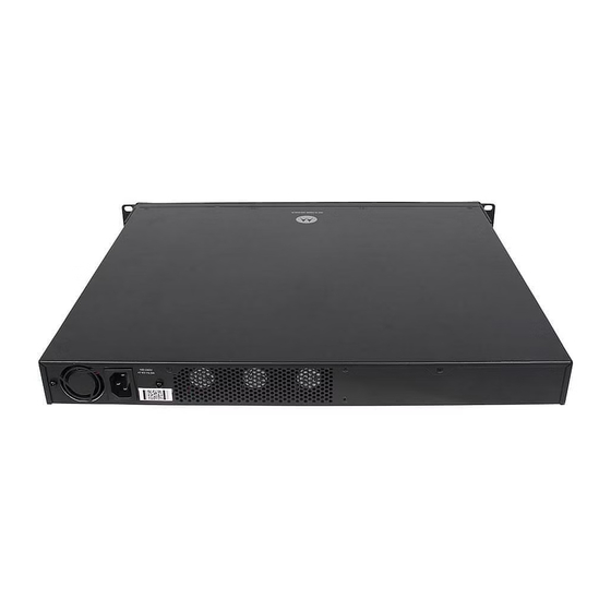
1-2 Motorola RF Switch Systen Reference 1.1 Hardware Overview The WS5100, RFS6000 and RFS7000 are rack-mountable devices that manage all inbound and outbound traffic on the wireless network. They provide security, network service and system management applications. Unlike traditional wireless infrastructure devices that reside at the edge of a network, the switch uses centralized, policy-based management to apply sets of rules or actions to all devices on the wireless network. - Page 13 Overview Operating Temperature 0°C - 40°C (32°F - 104°F) Operating Humidity 5% - 85% RH, non-condensing A power cord is not supplied with a WS5100, RFS6000 or RFS7000 model switch. Use only a correctly rated power cord certified for the country of operation...
-
Page 14: Software Overview
Motorola RFMS can help optimize the positioning and configuration of a switch in respect to a WLAN’s MU throughput requirements and can help detect rogue devices. For more information, refer to the Motorola Web site. - Page 15 Overview • Installation Feature • Licensing Support • Configuration Management • Diagnostics • Serviceability • Tracing / Logging • Process Monitor • Hardware Abstraction Layer and Drivers • Redundancy • Secure Network Time Protocol (SNTP) • Password Recovery 1.2.1.1 Installation Feature The upgrade/downgrade of the switch can be performed at boot time using one of the following methods: •...
- Page 16 1-6 Motorola RF Switch Systen Reference • Hardware – Ethernet ports, chip failures, system temperature via the temperature sensors provided by the hardware, etc. • Software – CPU load, memory usage, etc. • Environmental – CPU and air temperature, fans speed, etc.
- Page 17 Overview 1.2.1.8 Hardware Abstraction Layer and Drivers HAL) The Hardware Abstraction Layer ( provides an abstraction library with an interface hiding hardware/ platform specific data. Drivers include platform specific components such as Ethernet, Flash Memory storage and thermal sensors. 1.2.1.9 Redundancy Using the switch redundancy, up to 12 switches can be configured in a redundancy group (and provide group monitoring).
-
Page 18: Wireless Switching
1-8 Motorola RF Switch Systen Reference 1.2.2 Wireless Switching The switch includes the following wireless switching features: • Adaptive AP • Physical Layer Features • Rate Limiting • Proxy-ARP • HotSpot / IP Redirect • IDM (Identity Driven Management) •... - Page 19 Overview • Centralized Configuration Management & Compliance - Wireless configurations across distributed sites can be centrally managed by the wireless switch or cluster. • WAN Survivability - Local WLAN services at a remote sites are unaffected in the case of a WAN outage. •...
- Page 20 1-10 Motorola RF Switch Systen Reference Motorola vendor specific attributes. The switch extracts the rate limits from radius server response. When such attributes are not present, the global settings on the switch are then applied. 1.2.2.4 Proxy-ARP Proxy ARP is provided for MU's whose IP address is known. The WLAN generates an ARP reply on behalf of a MU (if the MU's IP address is known).
- Page 21 1-11 Overview 1.2.2.7 Voice Prioritization The switch has the capability of having its QoS policy configured to prioritize network traffic requirements for associated MUs. Use QoS to enable voice prioritization for devices using voice as its transmission priority. Voice prioritization allows you to assign priority to voice traffic over data traffic, and (if necessary) assign legacy voice supported devices (non WMM supported voice devices) additional priority.
- Page 22 • 802.11e admission control — 1 byte: channel utilization % and 1 byte: MU count is sent in QBSS Load Element in beacons to MU. • Motorola load balancing element (proprietary) — 2 byte: MU Count are sent in beacon to MU.
- Page 23 1-13 Overview AP Balancing Across Multiple Switches At adoption, the AP solicits and receives multiple adoption responses from the switches on the network. These adoption responses contain preference and loading information the AP uses to select the optimum switch to be adopted by. Use this mechanism to define which APs are adopted by which switches. By default, the adoption algorithm generally distributes AP adoption evenly among the switches available.
- Page 24 1-14 Motorola RF Switch Systen Reference MU Move Command As a value added proprietary feature between Motorola infrastructure products and Motorola MUs, a move command has been introduced. The move command permits an MU to roam between ports connected to the same switch without the need to perform the full association and authentication defined by the 802.11...
- Page 25 1-15 Overview disconnect. With QoS, a VoIP conversation (a real-time session), receives priority, maintaining a high level of voice quality. Voice QoS ensures: • Strict Priority • Spectralink Prioritization • VOIP Prioritization (IP ToS Field) • Multicast Prioritization Data QoS The switch supports the following data QoS techniques: •...
- Page 26 1-16 Motorola RF Switch Systen Reference 1.2.2.14 Wireless Layer 2 Switching The switch supports the following layer 2 wireless switching techniques: • WLAN to VLAN • MU User to VLAN • WLAN to GRE 1.2.2.15 Automatic Channel Selection Automatic channel selection works sequentially as follows: 1.
- Page 27 1-17 Overview Limiting Users Per VLAN Not all VLANs within a single WLAN must have the same DHCP pool size. Assign a user limit to each VLAN to allow the mapping of different pool sizes. Specify the VLAN user limit. This specifies the maximum number of MUs associated with a VLAN (for a particular WLAN).
-
Page 28: Wired Switching
1-18 Motorola RF Switch Systen Reference for future VLAN assignment. To configure Multiple VLANs for a single WLAN, see Assigning Multiple VLANs per WLAN on page 4-30. 1.2.3 Wired Switching The switch includes the following wired switching features: • DHCP Servers •... -
Page 29: Management Features
• A Command Line Interface (CLI) accessible via the serial port or through Telnet or a Secure Shell (SSH) application • A CLI Service mode enabling the capture of system status information that can be sent to Motorola personnel for use in problem resolution •... -
Page 30: Security Features
1-20 Motorola RF Switch Systen Reference 1.2.5 Security Features Switch security can be classified into wireless security and wired security. The switch includes the following wireless security features: • Encryption and Authentication • MU Authentication • Secure Beacon • MU to MU Disallow •... - Page 31 KeyGuard is Motorola’s proprietary dynamic WEP solution. Motorola (upon hearing of the vulnerabilities of WEP) developed a non standard method of rotating keys to prevent compromises. Basically, KeyGuard is TKIP without the message integrity check. KeyGuard is proprietary to Motorola MUs only. For information on configuring KeyGuard for a WLAN, see Configuring WEP 128 / KeyGuard on page 4-52.
- Page 32 1-22 Motorola RF Switch Systen Reference uses the MAC address of the MU as both the username and password (this configuration is also expected on the Radius server). MAC-Auth supports all encryption types, and (in case of 802.11i) the handshake is completed before the Radius lookup begins.
- Page 33 NOTE: The Motorola RF Management Software is recommended to plan the deployment of the switch. Motorola RFMS can help optimize the positioning and configuration of a switch in respect to a WLAN’s MU throughput requirements and can help detect rogue...
- Page 34 With this most recent switch firmware release, the switch can provide rogue device detection data to the Motorola RF Management software application (or Motorola RFMS). Motorola RFMS uses this data to refine the position and display the rogue on a site map representative of the physical dimensions of the actual radio coverage area of the switch.
- Page 35 1-25 Overview allowed. If the action is to mark, the packet is tagged for priority. The switch supports the following types of ACLs: • IP Standard ACLs • IP Extended ACLs • MAC Extended ACLs • Wireless LAN ACLs For information on creating an ACL, see Configuring Firewalls and Access Control Lists on page 6-19.
-
Page 36: Supported Access Ports/Points
NAC 802.1x support (printers, phones, PDAs etc.). For information on configuring NAC support, see Configuring NAC Server Support on page 4-48. 1.2.6 Supported Access Ports/Points A RF switch supports the adoption of the following Motorola Enterprise Access Ports and Access Points: • AP100 • AP300 • AP-5131... -
Page 37: Chapter 2. Switch Web Ui Access And Image Upgrades
Switch Web UI Access and Image Upgrades The content of this chapter is segregated amongst the following: • Accessing the Switch Web UI • Switch Password Recovery • Upgrading the Switch Image • Auto Installation • AP-4131 Access Point to Access Port Conversion 2.1 Accessing the Switch Web UI 2.1.1 Web UI Requirements The switch Web UI is accessed using Internet Explorer version 5.5 (or later) and SUN JRE (Java Runtime... - Page 38 This warning screen will continue to display on future login attempts until a self-signed certificate is implemented. Motorola recommends only using the default certificate for the first few login attempts until a self-signed certificate can be generated.
-
Page 39: Switch Password Recovery
Only an installation professional should reset the switch password and promptly define a new restrictive password. To contact Motorola Support in the event of a password reset requirement, go to http://www.symbol.com/contactsupport. -
Page 40: Upgrading The Switch Image
System Reference Guide. However, Motorola periodically releases switch firmware that includes enhancements or resolutions to known issues. Verify your current switch firmware version with the latest version available from the Motorola Web site before determining if your system requires an upgrade. 2.4 Auto Installation The switch auto install function can be configured manually or using a DHCP server. - Page 41 Switch Web UI Access and Image Upgrades • image file URL • expected image version To set default to no, and the URLs and the version default to "" (blank): RF Switch(config)#show autoinstall feature enabled config --not-set-- cluster cfg --not-set-- image --not-set-- expected image version...
-
Page 42: Ap-4131 Access Point To Access Port Conversion
To convert an AP-4131 “fat” Access Point to a “thin” AP-4131 Access Port you need to load the port conversion version firmware. Refer to the files available with you Motorola Web site download package. To convert an AP-4131 Access Point 1. - Page 43 Switch Web UI Access and Image Upgrades 5. Reset the AP if you changed the AP's IP address, buy displaying the System Summary and selecting the Reset AP option. If you reset the AP-4131 you will need to login as Admin again. 6.
- Page 44 2-8 Motorola RF Switch System Reference...
-
Page 45: Chapter 3. Switch Information
Motorola RFMS can help optimize the positioning and configuration of a switch (and its associated radios) in respect to a WLAN’s MU throughput requirements and can help detect rogue devices. -
Page 46: Setting The Switch Country Code
3-2 Motorola RF Switch System Reference NOTE: When the switch’s configuration is successfully updated (using the Web UI), the effected screen is closed without informing the user their change was successful. However, if an error were to occur, the error displays within the effected screen’s Status field and the screen remains displayed. - Page 47 Firmware Displays the current firmware version running on the switch. This version should be periodically compared to the most recent version available on the Motorola Web site, as versions with increased functionality are periodically released. AP Licenses Displays the number of Access Port licenses currently available for the switch.
-
Page 48: Switch Dashboard Details
(to the Time Zone or Country parameters specifically). 3.1.3 Switch Dashboard Details Each Motorola RF Switch platform contains a dashboard whichrepresents a high-level graphical overview of central switch processes and hardware. When logging into the switch, the dashboard should be the first place you go to assess overall switch performance and any potential performance issues. - Page 49 Switch Information 3.1.3.1 WS5100 Switch Dashboard Dashboard screen displays the current health of the switch and is divided into fields representing the following important diagnostics: • Alarms • Ports • Environment • CPU/Memory • File Systems Apart from the sections mentioned above, it also displays the following status: Redundancy State Displays the Redundancy State of the switch.
- Page 50 3-6 Motorola RF Switch System Reference Mobile Units Displays the total number of MUs associated with the switch. Up Time Displays the actual switch uptime. The Uptime is the current operational time of the device defined within the System Name field. Uptime is the cumulative time since the switch was last rebooted or lost power.
- Page 51 Switch Information 3.1.3.2 RFS6000 Switch Dashboard Dashboard screen displays the current health of the switch and is divided into fields representing the following important diagnostics: • Alarms • Ports • Environment • CPU/Memory • File Systems Apart from the sections mentioned above, it also displays the following status: Redundancy State Displays the Redundancy State of the switch.
- Page 52 3-8 Motorola RF Switch System Reference Mobile Units Displays the total number of MUs associated with the switch. Up Time Displays the actual switch uptime. The Uptime is the current operational time of the device defined within the System Name field. Uptime is the cumulative time since the switch was last rebooted or lost power.
- Page 53 Switch Information 3.1.3.3 RFS7000 Switch Dashboard Dashboard screen displays the current health of the switch and is divided into fields representing the following important diagnostics: • Alarms • Ports • Environment • CPU/Memory • File Systems Apart from the sections mentioned above, it also displays the following status: Redundancy State Displays the Redundancy State of the switch.
- Page 54 3-10 Motorola RF Switch System Reference Mobile Units Displays the total number of MUs associated with the switch. Up Time Displays the actual switch uptime. The Uptime is the current operational time of the device defined within the System Name field. Uptime is the cumulative time since the switch was last rebooted or lost power.
-
Page 55: Viewing Switch Statistics
3-11 Switch Information 3.1.4 Viewing Switch Statistics Switch Statistics tab displays an overview of the recent network traffic and RF status for the switch. To display the Switch Statistics tab: 1. Select Switch from the main menu tree. 2. Click the Switch Statistics tab at the top of the Switch screen. - Page 56 3-12 Motorola RF Switch System Reference Avg. Bit Speed Displays the average bit speed for the switch over last 30 seconds and 1 hour. Use the average bit speed value to help determine overall network speeds and troubleshoot network congestion.
-
Page 57: Viewing Switch Port Information
3-13 Switch Information 3.2 Viewing Switch Port Information Port screen displays configuration, runtime status and statistics of the ports on the switch. SWITCH NOTE: The ports available vary by switch platform. WS5100: eth1, eth2 RFS6000: ge1, ge2, ge3, ge4, ge5, ge6, ge7, ge8, me1, up1 RFS7000: ge1, ge2, ge3, ge4, me1 The port types are defined as follows: ETH#... - Page 58 3-14 Motorola RF Switch System Reference 2. Select the Configuration tab to display the following read-only information: Name Displays the current port name. The port names available vary by switch. WS5100: eth1, eth2 RFS6000: ge1, ge2, ge3, ge4, ge5, ge6, ge7, ge8, me1, up1...
- Page 59 3-15 Switch Information 2. Click the Edit button. Port Change Warning screen displays, stating any change to the port setting could disrupt access to the switch. Communication errors may occur even if modifications made are successful. 3. Click the button to continue. Optionally, select the Don’t show this message again for the rest of the session checkbox to disable...
-
Page 60: Viewing The Ports Runtime Status
3-16 Motorola RF Switch System Reference Name Displays the read-only name assigned to the port. Speed Select the speed at which the port can receive and transmit the data. Select from the following range: • 10 Mbps • 100 Mbps •... -
Page 61: Reviewing Port Statistics
3-17 Switch Information 2. Select the Runtime tab to display the following read-only information: Name Displays the port’s current name. MAC Address Displays the port’s MAC Address. This value is read-only, set at the factory and cannot be modified. Oper Status Displays the link status of the port. - Page 62 3-18 Motorola RF Switch System Reference 2. Select the Statistics tab. 3. Refer to the Statistics tab to display the following read-only information: Name Defines the port name. Bytes In Displays the total number of bytes received by the port.
- Page 63 3-19 Switch Information 2. Click the Details button. 3. The Interface Statistics screen displays. This screen displays the following statistics for the selected port: Name Displays the port name. MAC Address Displays physical address information associated with the interface. This address is read-only (hard-coded at the factory) and cannot be modified.
- Page 64 3-20 Motorola RF Switch System Reference Output Packets Displays the number of transmitted packets dropped from the interface. Output Dropped Packets Dropped are packets dropped when the output queue of the device associated with the interface is saturated. Output Packets Error Displays the number of transmitted packets with errors.
-
Page 65: Power Over Ethernet (Poe)
3-21 Switch Information • Input Pkts Total • Input Pkts Error • Output Pkts NUCast • Input Pkts NUCast • Output Bytes • Output Pkts Dropped 3. Display any of the above by selecting the checkbox associated with it. NOTE: You are not allowed to select (display) more than four parameters at any given time. - Page 66 3-22 Motorola RF Switch System Reference 2. Select the SWITCH NOTE: The PoE screen is only available on the RF6000 switch. The WS5100 and RFS7000 switches do not have Power over Ethernet on any ports and will not display the PoE tab.
-
Page 67: Editing Port Poe Settings
3-23 Switch Information Priority Displays the priority mode for each of the PoE ports. The priority options are: • Critical • High • Low Limit (watts) Displays the power limit in watts for each of the PoE ports. The maximum power limit per port is 29.7 watts. -
Page 68: Viewing Switch Configurations
Motorola RFMS can help optimize the positioning and configuration of a switch (and its associated radios) in respect to a WLAN’s MU throughput requirements and can help detect rogue devices. -
Page 69: Viewing The Detailed Contents Of A Config File
3.3.1 Viewing the Detailed Contents of a Config File The View screen displays the entire contents of a configuration file. Motorola recommends a file be reviewed carefully before it is selected from the Config Files screen for edit or designation as the switch startup configuration. -
Page 70: Transferring A Config File
3-26 Motorola RF Switch System Reference Use the up and down navigation facilities on the right-hand side of the screen to view the entire page. 3. The Page parameter displays the portion of the configuration file in the main viewing area. - Page 71 3-27 Switch Information 1. Click the Transfer Files button on the bottom of the Configuration screen. 2. Refer to the Source field to define the location and address information for the source config file. From Select the location representing the source file’s current location using the From drop-down menu.
-
Page 72: Viewing Switch Firmware Information
3-28 Motorola RF Switch System Reference 3.4 Viewing Switch Firmware Information The switch can store (retain) two software versions (primary and secondary). Information supporting the two versions displays within the Firmware screen. The Version column displays the version string. The... -
Page 73: Editing The Switch Firmware
3-29 Switch Information 3. Refer to the Patch field for a listing of those Patches available to the switch. The name and version of each patch file is displayed. Each patch file has an associated .txt file designation. the text file describes nuances associated with the file that may make it optimal for use with the switch. -
Page 74: Enabling Global Settings For The Image Failover
3-30 Motorola RF Switch System Reference 3.4.2 Enabling Global Settings for the Image Failover Use the Global Settings screen to specify a firmware version for use with the failover image. SWITCH NOTE: The Global Settings for Image Failover is only available on the WS5100 switch. - Page 75 3-31 Switch Information 3. Use the From drop-down menu to specify the location from which the file is sent. 4. Enter the name of the file containing the firmware update in the File text field. This is the file that will append the file currently in use. 5.
-
Page 76: Switch File Management
3-32 Motorola RF Switch System Reference 3.5 Switch File Management Use the File Management screen to transfer configuration file to and from the switch and review the files available. 3.5.1 Transferring Files Use the Transfer Files screen to transfer files to and from the switch.Transferring files is recommended to keep files in a secure location. - Page 77 3-33 Switch Information 3.5.1.1 Transferring a file from Wireless Switch to Wireless Switch To transfer a file from one switch to another: 1. Select Wireless Switch from the From drop-down menu 2. Use the Browse button to locate a target file for the file transfer. 3.
- Page 78 3-34 Motorola RF Switch System Reference 1. Refer to the Source field to specify the source file. Use the From drop-down menu and select Wireless Switch. 2. Use the Browse button and select a file for transfer. 3. Use the drop-down menu (within the Target field) and select Server.
-
Page 79: Viewing Files
3-35 Switch Information 1. Refer to the Source field to specify the details of the source file. Use the From drop-down menu and select Server. 2. Provide the name of the File. 3. Use the Using drop-down menu to configure whether the file transfer is conducted using FTP, TFTP or HTTP. - Page 80 3-36 Motorola RF Switch System Reference • nvram • system • Compact Flash • USB 1 • USB 2 SWITCH NOTE: USB 1 is available on the RFS6000 and RFS7000 switches. USB2 and Compact Flash are only available on the RFS7000 switch. Neither USB or Compact Flash are supported on the WS5100 switch.
-
Page 81: Configuring Automatic Updates
Enable this option for either the firmware, configuration file or cluster configuration file. Motorola recommends leaving this setting disabled if a review of a new file is required before it is automatically uploaded by the switch. - Page 82 3-38 Motorola RF Switch System Reference 2. Refer to the Switch Configuration field to enable and define the configuration for automatic configuration file updates. If enabled, the located (updated) configuration file will be used with the switch the next time the switch boots.
- Page 83 3-39 Switch Information 4. Refer to the Firmware field to enable and define the configuration for automatic firmware updates. If enabled, the located (updated) switch firmware is used with the switch the next time the switch boots. Enable Select the Enable checkbox to allow an automatic firmware update when a new (updated) version is detected (upon the boot of the switch) at the specified IP...
-
Page 84: Viewing The Switch Alarm Log
3-40 Motorola RF Switch System Reference 3.7 Viewing the Switch Alarm Log Use the Alarm Log screen as an initial snapshot for alarm log information. Expand alarms (as needed) for greater detail, delete alarms, acknowledge alarms or export alarm data to a user-specified location for archive and network performance analysis. -
Page 85: Viewing Alarm Log Details
3-41 Switch Information Time Stamp Displays the date, year and time the alarm was raised (as well as the time zone of the system). The time stamp only states the time the alarm was generated, not the time it was acknowledged. Severity Displays the severity level of the event. -
Page 86: Viewing Switch Licenses
3-42 Motorola RF Switch System Reference 2. Select an alarm and click the Details button. 3. Refer to the Alarm Details Alarm Message for the following information: Description Displays the details of the alarm log event. This information can be used in... - Page 87 License Key Enter the license key required to install a particular feature. The license key is returned when you supply the switch serial number to Motorola support. Feature Name Enter the name of the feature you wish to install/upgrade using the license.
-
Page 88: How To Use The Filter Option
3-44 Motorola RF Switch System Reference 3.9 How to use the Filter Option Use the Filter Option to sort the display details of screen that employ the filtering option as a means of sorting how data is displayed within the screen. -
Page 89: Chapter 4. Network Setup
Network Setup This chapter describes the Network Setup menu information used to configure the switch. This chapter consists of the following switch Network configuration activities: • Displaying the Network Interface • Viewing Network IP Information • Viewing and Configuring Layer 2 Virtual LANs •... -
Page 90: Displaying The Network Interface
4-2 Motorola RF Switch System Reference Guide 4.1 Displaying the Network Interface The main Network interface displays a high-level overview of the configuration (default or otherwise) as defined within the Network main menu. Use the information to determine if items require additional configuration using the sub-menu items under the main Network menu item. - Page 91 Network Setup 2. Refer to the following information to discern if configuration changes are warranted: DNS Servers Displays the number of DNS Servers configured thus far for use with the switch. For more information, see Viewing Network IP Information on page 4-4.
-
Page 92: Viewing Network Ip Information
4-4 Motorola RF Switch System Reference Guide 4.2 Viewing Network IP Information Use the Internet Protocol screen to view and configure network associated IP details. The Internet Protocol screen contains tabs supporting the following configuration activities: • Configuring DNS •... - Page 93 Network Setup 6. Click the Global Settings button to open a screen that allows the domain lookup to be enabled/disabled and the domain name to be specified. For more information, see Configuring Global Settings on page 4-5. 4.2.1.1 Adding an IP Address for a DNS Server Add an IP address for a new domain server using the screen.
-
Page 94: Configuring Ip Forwarding
4-6 Motorola RF Switch System Reference Guide 6. Click Cancel to close the dialog without committing updates to the running configuration. 4.2.2 Configuring IP Forwarding The IP Forwarding table lists all the routing entries to route the packets to a specific destination. To view the IP forwarding configuration: 1. - Page 95 Network Setup Protocol Displays the name of the routing protocol with which this route was obtained. Possible values are: • Static — Routes are statically added by the operator. • DHCP — Routes obtained from the DHCP server. • Connected — Routes automatically installed by the switch for directly connected networks based on interface IP addresses.
-
Page 96: Viewing Address Resolution
4-8 Motorola RF Switch System Reference Guide 7. Click Cancel to close the dialog without committing updates to the running configuration. 4.2.3 Viewing Address Resolution Address Resolution table displays the mapping of layer three (IP) addresses to layer two (MAC) addresses. -
Page 97: Viewing And Configuring Layer 2 Virtual Lans
Network Setup 4.3 Viewing and Configuring Layer 2 Virtual LANs A virtual LAN (VLAN) is similar to a Local Area Network (LAN), however devices do not need to be connected to the same segment physically. Devices operate as if connected to the same LAN, but could be connected at different physical connections across the LAN segment. -
Page 98: Editing The Details Of An Existing Vlan By Port
4-10 Motorola RF Switch System Reference Guide Allowed VLANs Displays VLAN tags allowed on this interface Native VLAN Tagged Displays if the Native VLAN for each port is tagged or not. The column displays a green check mark if the Native VLAN is tagged. If the Native VLAN is not tagged the column will display a red “x”. -
Page 99: Viewing And Configuring Ports By Vlan
4-11 Network Setup 5. Use the Edit screen to modify the following: Name Displays a read only field and with the name of the Ethernet to which the VLAN is associated. Mode Use the drop-down menu to select the mode. It can be either: •... - Page 100 4-12 Motorola RF Switch System Reference Guide 2. Select the Ports by VLAN tab. VLAN details display within the VLANs by Port tab. 3. Highlight an existing VLAN and click the Edit button. The system displays a Port VLAN Change Warning message.
-
Page 101: Configuring Switch Virtual Interfaces
4-13 Network Setup 5. Change VLAN port designations as required. 6. Click to use the changes to the running configuration and close the dialog. 7. Click Cancel to close the dialog without committing updates to the running configuration. 4.4 Configuring Switch Virtual Interfaces A switch virtual interface (SVI) is required for layer 3 (IP) access to the switch or provide layer 3 service on a VLAN. - Page 102 4-14 Motorola RF Switch System Reference Guide DHCP Displays whether the DHCP client is enabled or not. A green check mark defines the DHCP client as enabled for the interface. A red X means the interface is disabled. Primary IP Address Displays the IP address for the virtual interface.
- Page 103 4-15 Network Setup 3. Click on the button. 4. Enter the VLAN ID for the switch virtual interface. 5. Provide a Description for the VLAN, representative of the VLAN’s intended operation within the switch managed network. 6. The Primary IP Settings field consists of the following: a.
-
Page 104: Viewing Virtual Interface Statistics
4-16 Motorola RF Switch System Reference Guide 2. Select the Configuration tab and click the Edit button. The screen displays with the name of the VLAN in the upper left-hand side. The VLAN ID cannot be modified and should be used to associate the VLAN ID with the description and IP address assignments defined. - Page 105 4-17 Network Setup 2. Select the Statistics tab. Refer to the following to assess the network throughput of existing virtual interfaces: Name Displays the user defined interface name. The corresponding statistics are displayed along the row. The statistics are the total traffic to the interface since its creation.
- Page 106 4-18 Motorola RF Switch System Reference Guide Packets In Error Displays the number of error packets coming into the interface. • Runt frames — Packets shorter than the minimum Ethernet frame length (64 bytes). • CRC errors — The Cyclical Redundancy Check (CRC) is the 4 byte field at the end of every frame the receiving station uses to interpret if the frame is valid.
- Page 107 4-19 Network Setup 3. The Interface Statistics screen displays with the following content: Name Displays the title of the logical interface selected. MAC Address Displays physical address information associated with the interface. This address is read-only (hard-coded at the factory) and cannot be modified. Input Bytes Displays the number of bytes received by the interface.
- Page 108 4-20 Motorola RF Switch System Reference Guide 4.4.2.2 Viewing the Virtual Interface Statistics Graph The switch Web UI continuously updates its virtual interface statistics, even when the graph is closed. Periodically display the virtual statistics graph for the latest information as network performance information is required.
-
Page 109: Viewing And Configuring Switch Wlans
4-21 Network Setup 4. Refer to the Status field for the current state of the requests made from applet. This field displays error messages if something goes wrong in the transaction between the applet and the switch. 5. Click Close to close the dialog. - Page 110 4-22 Motorola RF Switch System Reference Guide 2. Click the Configuration tab. The Configuration tab displays the following details: Switch Switch field displays the IP address of the cluster member associated with each WLAN. When clustering is enabled on the switch and...
- Page 111 4-23 Network Setup Encryption Displays the type of wireless encryption used on the specified WLAN. When no encryption is used, the field displays "none". Click the Edit button to modify the WLAN’s current encryption scheme. For information on configuring an authentication scheme for a WLAN, see Configuring Different Encryption Types on page...
- Page 112 4-24 Motorola RF Switch System Reference Guide 7. Click the Global Settings button to display a screen with WLAN settings applying to the all the WLANs on the system. Remember, changes made to any one value impact each WLAN. Click to save updates to the Global WLAN Settings screen.
- Page 113 4-25 Network Setup MU Rate Limiting Enter an downstream rate limit in kbps for all MUs associated with the switch Down across all WLANs. MU Load Balance Configure a method for distributing traffic across MUs using the MU Load Mode Balancing Mode.
- Page 114 4-26 Motorola RF Switch System Reference Guide 4. Click the Edit button. The Wireless LANs Edit screen is divided into the following user-configurable fields: • Switch IP • Configuration • Authentication • Encryption • Advanced 5. The Switch field displays the IP address of the cluster member associated with each WLAN. When clustering is enabled on the switch and Cluster GUI is enabled the Switch field will be available on the Wireless LAN screen.
- Page 115 4-27 Network Setup Independent Mode Determines whether the WLAN is functioning as an independent or extended (AAP Only) WLAN in regards its support of adaptive AP (AAP) operation. Select the checkbox to designate the WLAN as independent and prevent traffic from being forwarded to the switch.
- Page 116 For detailed information on configuring WEP 128 for the WLAN, see Configuring WEP 128 / KeyGuard on page 4-52. KeyGuard Uses a Motorola proprietary encryption mechanism to protect data. For detailed information on configuring KeyGuard for the WLAN, see Configuring WEP 128 / KeyGuard on page 4-52.
- Page 117 Select the Use Voice Prioritization option if Voice is used on the WLAN. This gives Prioritization priority to voice packets and voice management packets and is supported only on certain legacy Motorola VOIP phones. Enable SVP Enabling SVP (Spectralink Voice Prioritization) allows the switch to identify and prioritize traffic from Spectralink/Polycomm phones.
- Page 118 4-30 Motorola RF Switch System Reference Guide MCast Addr 2 The second address also takes packets (where the first 4 bytes match the first 4 bytes of the mask) and sends them immediately over the air instead of waiting for the DTIM period.
- Page 119 4-31 Network Setup 6. Configure the Multiple VLAN Mapping for WLAN table as required to add or remove multiple VLANS for the selected WLAN. Multiple VLAN’s per WLAN are mapped (by default) to a regular VLAN and are not supported on an adaptive AP.
- Page 120 4-32 Motorola RF Switch System Reference Guide 4.5.1.3 Configuring Authentication Types Refer to the following to configure the WLAN authentication options available on the switch: • Configuring 802.1x EAP • Configuring Kerberos • Configuring Hotspots • Configuring an Internal Hotspot •...
- Page 121 Once a MU and server prove their identity, they can encrypt all communications to assure privacy and data integrity. Kerberos can only be used with Motorola clients. CAUTION: Kerberos makes no provisions for host security. Kerberos assumes it is running on a trusted host with an untrusted network.
- Page 122 4-34 Motorola RF Switch System Reference Guide 5. Click the Config button to the right of the Kerberos checkbox. The Kerberos screen displays. 6. Specify a case-sensitive Realm Name. The realm name is the name domain/realm name of the KDC Server. A realm name functions similarly to a DNS domain name.
- Page 123 4-35 Network Setup 3. Customized internal Web page (using the Advanced feature in hotspot configuration) When a user visits a public hotspot and wants to browse a Web page, they can boot up their laptop and associate with the local Wi-Fi network by entering the correct SSID. They then start a browser. The hotspot access controller forces this un-authenticated user to a Welcome page from the hotspot Operator that allows the user to login with a username and password.
- Page 124 4-36 Motorola RF Switch System Reference Guide Configuring Advanced Hotspot on page 4-42. NOTE: The appearance of the Hotspot screen differs depending on which option is selected from the drop-down menu. You may want to research the options available before deciding which hotspot option to select.
- Page 125 4-37 Network Setup 3. Select the Hotspot button from within the Authentication field. Ensure Internal is selected from within This WLAN’s Web Pages are of the drop-down menu. 4. Click the tab and enter the title, header, footer Small Logo URL, Main Logo URL and Descriptive Login Text you would like to display when users login to the switch maintained hotspot.
- Page 126 4-38 Motorola RF Switch System Reference Guide Main Logo URL Displays the URL for the main logo image displayed on the Failed page when using the switch’s internal Web server. This option is only available if Internal is chosen from the drop-down menu above.
- Page 127 4-39 Network Setup Main Logo URL The Main Logo URL is the URL for the main logo image displayed on the Failed page when using the internal Web server. This option is only available if Internal is chosen from the drop-down menu above. Descriptive Text Specify any additional text containing instructions or information for the users who access the Failed page on the internal Web server.
- Page 128 4-40 Motorola RF Switch System Reference Guide 3. Select the Hotspot button from within the Authentication field. Ensure External is selected from within This WLAN’s Web Pages are of the drop-down menu. 4. Refer to the External Web Pages field and provide the Login, Welcome and Failed Page URLs used by the external Web server to support the hotspot.
- Page 129 4-41 Network Setup Welcome Page URL Define the complete URL for the location of the Welcome page. The Welcome page assumes the hotspot user has logged in successfully and can access the Internet. Ensure that that RADIUS server port number is included in the URL using the following format: https://192.168.0.70:444/wlan2/login.html Failed Page URL...
- Page 130 4-42 Motorola RF Switch System Reference Guide Configuring Advanced Hotspot A customer may wish to use advanced Web content (XML, Flash) but might not have (or would not want to use) an external Web server, choosing instead to host the Web pages on the switch's HTTP Web server.
- Page 131 4-43 Network Setup a. Specify a source hotspot configuration file. The file used at startup automatically displays within the File parameter. b. Refer to the Using drop-down menu to configure whether the hotspot file transfer is conducted using FTP or TFTP. c.
- Page 132 (default users are admin with superuser privileges and operator with monitor privileges). No secondary authentication source is specified. However, Motorola recommends using an external Radius Server as the primary user authentication source and the local switch Radius Server as the secondary user authentication source.
- Page 133 To configure an external Radius Server for EAP 802.1x, Hotspot or Dynamic MAC ACL WLAN support: NOTE: To optimally use an external Radius Server with the switch, Motorola recommends defining specific external Server attributes to best utilize user privilege values for specific switch permissions.
- Page 134 4-46 Motorola RF Switch System Reference Guide 6. Refer to the Server field and define the following credentials for a primary and secondary Radius server. RADIUS Server Enter the IP address of the primary and secondary server acting as the Radius user Address authentication data source.
- Page 135 Configuring an External Radius Server for Optimal Switch Support The switch’s external Radius Server should be configured with Motorola RF Switch specific attributes to best utilize the user privilege values assignable by the Radius Server. The following two values should be configured on the external Server for optimal use with the switch: •...
- Page 136 4-48 Motorola RF Switch System Reference Guide access, configure the Radius Server with two attributes. Once with a value 1 for monitor access and then with a value 2 for the helpdesk role. Multiple roles can also be defined by configuring the Radius Server with attribute 1 and value 3 (or monitor value 1 and helpdesk value 2).
- Page 137 4-49 Network Setup 1. Select Network > Wireless LANs from the main menu tree. 2. Select an existing WLAN from those displayed with the Configuration tab. 3. Click on the Edit button. 4. Select either the 802.1x, Hotspot Dynamic MAC ACL button from within the Authentication field.
- Page 138 4-50 Motorola RF Switch System Reference Guide Server Timeout Enter a value (between 1 and 300 seconds) to indicate the number of elapsed seconds causing the switch to time out on a request to the primary or secondary NAC server.
- Page 139 4-51 Network Setup 11.Refer to the Status field for the current state of the requests made from applet. This field displays error messages if something goes wrong in the transaction between the applet and the switch. 12.Click to use the changes to the running configuration and close the dialog. 13.Click Cancel to close the dialog without committing updates to the running configuration.
- Page 140 Generate button. The pass key can be any alphanumeric string. The switch, other proprietary routers and Motorola MUs use the algorithm to convert an ASCII string to the same hexadecimal number. MUs without Motorola adapters need to use WEP keys manually configured as hexadecimal numbers.
- Page 141 Generate button. The pass key can be any alphanumeric string. The switch and Motorola MUs use the algorithm to convert an ASCII string to the same hexadecimal number. MUs without Motorola adapters need to use WEP keys manually configured as hexadecimal numbers.
- Page 142 4-54 Motorola RF Switch System Reference Guide Configuring WPA/WPA2 using TKIP and CCMP Wi-Fi Protected Access (WPA) is a robust encryption scheme specified in the IEEE Wireless Fidelity (Wi-Fi) standard, 802.11i. WPA provides more sophisticated data encryption than WEP. WPA is designed for corporate networks and small-business environments where more wireless traffic allows quicker discovery of encryption keys by an unauthorized person.
- Page 143 4-55 Network Setup 5. Select the Broadcast Key Rotation checkbox to enable periodically changing the broadcast key for this WLAN. Only broadcast key changes when required by associated MUs to reduce the transmissions of sensitive key information. This value is enabled by default. 6.
-
Page 144: Viewing Wlan Statistics
4-56 Motorola RF Switch System Reference Guide Opportunistic Key Opportunistic Key Caching allows the switch to use a PMK derived with a Caching client on one Access Port with the same client when it roams over to another Access Port. Upon roaming, the client does not have to conduct 802.1x authentication and can start sending/receiving data sooner. - Page 145 4-57 Network Setup 3. Refer to the following details displayed within the table: Last 30s Click the Last 30s radio button to display statistics for the WLAN over the last 30 seconds. This option is helpful when troubleshooting issues as they actually occur. Last Hr Click the Last Hr radio button to displays statistics for the WLAN over the last 1 hour.
- Page 146 4-58 Motorola RF Switch System Reference Guide 3. Select a WLAN from the table displayed in the Statistics screen. and click the Details button. v The Details screen displays the WLAN statistics of the selected WLAN. The Details screen contains the following fields: •...
- Page 147 4-59 Network Setup 5. Refer to the Traffic field for the following information (both received and transmitted): Pkts per second Displays the average total packets per second that cross the selected WLAN. The Rx column displays the average total packets per second received on the selected WLAN.
- Page 148 4-60 Motorola RF Switch System Reference Guide 4.5.2.2 Viewing WLAN Statistics in a Graphical Format The switch Web UI continuously collects WLAN statistics even when the graph is not displayed. Periodically display the WLAN statistics graph for the latest WLAN throughput and performance information.
- Page 149 WLAN. NOTE: The Motorola RF Management Software is recommended to plan the deployment of the switch. Motorola RFMS can help optimize the positioning and configuration of a switch in respect to a WLAN’s MU throughput requirements. For more information, refer to the Motorola Web site.
-
Page 150: Configuring Wmm
4-62 Motorola RF Switch System Reference Guide 4.5.3 Configuring WMM Use the tab to review a WLAN’s current index (numerical identifier), SSID, description, current enabled/disabled designation, and Access Category. To view existing WMM Settings: 1. Select Network > Wireless LANs from the main menu tree. - Page 151 4-63 Network Setup AIFSN Displays the current Arbitrary Inter-frame Space Number (AIFSN). Higher-priority traffic categories should have lower AIFSNs than lower-priority traffic categories. This will causes lower-priority traffic to wait longer before trying attempting access. Transmit Ops Displays the maximum duration a device can transmit after obtaining a transmit opportunity.
- Page 152 4-64 Motorola RF Switch System Reference Guide 4. Select the QoS Mappings button to revise the existing mappings of access category to 802.1p and DSCP to access category settings. With a drastic increase in bandwidth absorbing network traffic (VOIP, multimedia etc.), the importance of data prioritization is critical to effective network management.
- Page 153 4-65 Network Setup 4.5.3.1 Editing WMM Settings WLAN WMM configuration affects your upstream traffic parameters. Use Configuring WMM on page 4-102 to configure downstream traffic parametersUse the WMM Edit screen to modify existing Access Category settings for the WLAN selected within the WMM screen. This could be necessary in instances when data traffic has changed and high-priority traffic (video and voice) must be accounted for by modifying AIFSN Transmit Ops and CW values.
-
Page 154: Configuring The Nac Inclusion List
4-66 Motorola RF Switch System Reference Guide Transmit Ops Define the maximum duration a device can transmit after obtaining a transmit opportunity. For higher-priority traffic categories, this value should be set to a low number. CW Minimum The CW Minimum is combined with the CW Maximum to make the Contention screen. - Page 155 4-67 Network Setup To view the attributes of a NAC Include list: 1. Select Network > Wireless LANs from the main menu tree. 2. Select the NAC Include List Configuration tab to view and configure NAC enabled devices. 3. The Include Lists field displays the list of devices that can be included on a WLAN (a printer for example).
- Page 156 4-68 Motorola RF Switch System Reference Guide 4.5.4.1 Adding an Include List to a WLAN To add a device to a WLAN’s include list configuration: 1. Select Network > Wireless LANs from the main menu tree. 2. Select the NAC Include tab to view and configure NAC Include enabled devices.
- Page 157 4-69 Network Setup 8. Click to save and add the new configuration and close the dialog window. 9. Click Cancel to close the dialog without committing updates to the running configuration. 4.5.4.3 Mapping Include List Items to WLANs To assign include list items to a one or more WLANs: 1.
-
Page 158: Configuring The Nac Exclusion List
4-70 Motorola RF Switch System Reference Guide 4.5.5 Configuring the NAC Exclusion List The switch provides a means to bypass NAC for 802.1x devices without a NAC agent. For Motorola handheld devices (like the MC9000), authentication is achieved using an exclusion list. - Page 159 4-71 Network Setup 5. The Configured WLANs field displays the available switch WLANs. Associate a list item in the Exclude Lists field with multiple WLANs. For information on mapping NAC Exclude list’s items to WLANs, see Mapping Exclude List Items to WLANs on page 4-72.
- Page 160 4-72 Motorola RF Switch System Reference Guide 3. Click on the button in the List Configuration field. 4. The List Name displays the read-only name of the list for which you wish to add more devices. 5. Enter the Host Name for the device you wish to add for the selected exclude list.
-
Page 161: Nac Configuration Examples Using The Switch Cli
The following are NAC include list, exclude list and WLAN configuration examples using the switch CLI interface: 4.5.6.1 Creating an Include List Since few devices require NAC, Motorola recommends using the "bypass-nac-except-include-list" option. Refer to the commands below to create a NAC Include List: 1. Create a NAC include list. - Page 162 4-74 Motorola RF Switch System Reference Guide 3. Associate the exclude list to a WLAN. RF Switch(config-wireless-client-list) #wlan 1 RF Switch(config-wireless-client-list) # 4.5.6.3 Configuring the WLAN for NAC Many handheld devices are required to bypass NAC and a few laptops and desktops are required to be NAC validated.
- Page 163 4-75 Network Setup RF Switch (config-wireless) #wlan 1 radius-server secondary radius-key my-rad-secret-2 RF Switch (config-wireless) # 4. Configure the NAC server’s timeout and re-transmit settings. The timeout parameter configures the duration for which the switch waits for a response from the Radius server before attempting a retry. This is a global setting for both the primary and secondary server.
-
Page 164: Viewing Associated Mu Details
• Viewing MU Statistics NOTE: The Motorola RF Management Software is a recommended utility to plan the deployment of the switch and view its configuration once operational. Motorola RFMS can help optimize switch positioning and configuration in respect to a WLAN’s MU throughput requirements and can help detect rogue devices. -
Page 165: Viewing Mu Details
4-77 Network Setup IP Address Displays the unique IP address for the MU. Use this address as necessary throughout the applet for filtering and device intrusion recognition and approval. Ready Displays whether the MU is ready for switch interoperation. Values are Yes and Power Save Displays the current (read-only) Power-Save-Poll (PSP) state of the MU. - Page 166 4-78 Motorola RF Switch System Reference Guide 3. Select a MU from the table in the Status screen and click the Details button. 4. Refer to the following read-only MU’s transmit and receive statistics:. MAC Address Displays the Hardware or Media Access Control (MAC) address for the MU.
-
Page 167: Configuring Mobile Units
4-79 Network Setup Voice Displays whether or not the MU is a voice capable device. Traffic from a voice enabled MU is handled differently than traffic from MUs without this capability. MUs grouped to particular WLANs can be prioritized to transmit and receive voice traffic over data traffic. - Page 168 4-80 Motorola RF Switch System Reference Guide MAC Address Each MU has a unique Media Access Control (MAC) address through which it is identified. This address is burned into the ROM of the MU. MAC Name MAC Name is a user created name used to identify individual mobile unit MAC Addresses with a user friendly name.
-
Page 169: Viewing Mu Statistics
4-81 Network Setup 4.6.3 Viewing MU Statistics Statistics screen displays read-only statistics for each MU. Use this information to assess if configuration changes are required to improve network performance. If a more detailed set of MU statistics is required, select a MU from the table and click the Details button. - Page 170 4-82 Motorola RF Switch System Reference Guide Throughput Mbps Displays the average throughput in Mbps between the selected MU and the Access Port. The Rx column displays the average throughput in Mbps for packets received on the selected MU from the Access Port. The Tx column displays the average throughput for packets sent on the selected MU from the Access Port.
- Page 171 4-83 Network Setup • Information • Traffic • RF Status • Errors Information in black represents the statistics from the last 30 seconds and information in blue represents statistics from the last hour. Use both sets of data to trend stats in real time versus a measurable period (1 hour).
- Page 172 4-84 Motorola RF Switch System Reference Guide 7. Refer to the Errors field for the following information: Avg Num of Retries Displays the average number of retries for the selected MU. Use this information to assess potential performance issues. % Gave Up Pkts Displays the percentage of packets the switch gave up on for the selected MU.
-
Page 173: Viewing Access Port Information
Access Ports. However, port adoption per switch is determined by the number of licenses acquired. NOTE: The Motorola RF Management Software is a recommended utility to plan the deployment of the switch and view its configuration once operational. Motorola RFMS can help optimize the positioning and configuration of a switch and Access Ports in respect to a WLAN’s MU throughput requirements. - Page 174 Description Displays a user assigned name for the radio. AP Type Displays the type of Access Port detected. The switches support Motorola AP 100, AP300 model Access Ports and AP-4131, AP-5131 and AP-7131 model Access Points. Type Use the Type to identify whether the radio is 802.11a radio or an 802.11bg radio.
- Page 175 4-87 Network Setup 4. Refer to the Properties field for the following Desired Channel When the radio’s channel is configured statically, the Actual Channel and Desired Channel are the same. If using ACS (Automatic Channel Selection), the switch selects a channel for the radio. The Desired Channel displays “ACS” and the Actual channel displays the channel selected for the radio.
- Page 176 WMM admission control is a mechanism for limiting traffic on a given access category. Per therecommendation of the 802.11e specification, Motorola limits support of this feature to voice and video. The switch configures the AP to broadcast that admission control is mandatory.
- Page 177 4-89 Network Setup 7. To use WIPS enter a Primary WIPS Server Address Secondary WIPS Server Address into the corresponding fields. 8. Click the Configure Port Authentication button to open a new dialogue with port authentication configuration information. 9. Click to save the changes and return to the previous screen.
- Page 178 4-90 Motorola RF Switch System Reference Guide 4.7.1.2 Editing AP Settings Edit screen provides a means of modifying the properties of an existing radio. This is often necessary when the radio’s intended function has changed and its name needs modification or if the radio now needs to be defined as a detector radio.
- Page 179 MU RSSI information. RSSI data (as obtained by at least three detecting radios) can be used by the Motorola RFMS application to triangulate the location of a MU on a site map representative of the actual physical dimensions of the switch radio coverage area.
- Page 180 4-92 Motorola RF Switch System Reference Guide RF coverage in WLAN environments that have more electromagnetic interference or greater distances between the Access Port and MUs. Decrease the power level according to the proximity of other Access Ports. Overlapping RF coverage may cause lost packets and problems for roaming devices trying to connect to an Access Port.
- Page 181 4-93 Network Setup Specify a Request To Send (RTS) threshold (in bytes) for use by the WLAN's adopted RTS Threshold Access Ports. RTS is a transmitting station's signal that requests a Clear To Send (CTS) response from a receiving station. This RTS/CTS procedure clears the air where many MUs are contending for transmission time.
- Page 182 4-94 Motorola RF Switch System Reference Guide Self Healing Offset When an Access Port increases its power to compensate for a failure, power is increased to the country's regulatory maximum. Set the Self Healing Offset to reduce the country's regulatory maximum power if Access Ports are situated close to each other or if an Access Port uses an external antenna.
- Page 183 4-95 Network Setup Supported rates allow an 802.11 network to specify the data rate it supports. When a MU attempts to join the network, it checks the data rate used on the network. If a rate is selected as a basic rate, it is automatically selected as a supported rate.
-
Page 184: Viewing Ap Statistics
4-96 Motorola RF Switch System Reference Guide 3. Click the button to display at screen containing settings for adding a radio 4. Enter the device MAC Address (the physical MAC address of the radio). Ensure this address is the actual hard-coded MAC address of the device. - Page 185 4-97 Network Setup 2. Click the Statistics tab. 3. To select the time frame for the radio statistics, select either Last 30s Last Hr above the statistics table. • Select the Last 30s radio button to display statistics for the last 30 seconds for the radio. •...
- Page 186 4-98 Motorola RF Switch System Reference Guide 5. Select a radio from those displayed and click the Details button for additional radio information in rae data format. For more information, see Viewing AP Statistics in Detail on page 4-98. 6. Select a radio from those displayed and click the...
- Page 187 4-99 Network Setup Avg Bit Speed Displays the average bit speed in Mbps on the selected radio. This includes all packets that are sent and received. The number in black represents this statistic for the last 30 seconds and the number in blue represents this statistic for the last hour.
-
Page 188: Configuring Wlan Assignment
4-100 Motorola RF Switch System Reference Guide 3. Select a radio index from the table displayed in the Statistics screen and click the Graph button. 4. Select a checkbox to display that metric charted within the graph. Do not select more than four checkboxes at any one time. - Page 189 4-101 Network Setup 3. Select a radio from the table to view WLAN assignment information. The WLAN Assignment tab is divided into two fields; Select Radios Assigned WLANs. 4. Refer to the Select Radios field for the following information Index Displays the numerical index (device identifier) used with the radio.
-
Page 190: Configuring Wmm
4-102 Motorola RF Switch System Reference Guide 3. Select a radio from the table and click the Edit button. Select Radio/BSS field displays the WLANs associated to each of the BSSIDs used by the radios within the radio table. Use Select/Change Assigned WLANs field to edit the WLAN assignment. - Page 191 4-103 Network Setup 2. Click the tab. WMM information displays per radio with the following information: Index Displays the identifier assigned to each Radio index, each index is assigned a unique identifier such as (1/4, 1/3, etc.). Displays the name of the Access Port associated with the index. The Access Port name comes from the description field in the Radio Configuration screen.
- Page 192 4-104 Motorola RF Switch System Reference Guide 4. Select a radio and click the Edit button to modify its properties. For more information, see Editing WMM Settings on page 4-104. 4.7.4.1 Editing WMM Settings Use the Edit screen to modify a WMM profile's properties (AIFSN, Tx Op, Cw Min and CW Max). Modifying these properties may be necessary as Access Categories are changed and transmit intervals need to be adjusted to compensate for larger data packets and contention windows.
-
Page 193: Configuring Access Point Radio Bandwidth
4-105 Network Setup 8. Refer to the Status field for the current state of the requests made from applet. This field displays error messages if something goes wrong in the transaction between the applet and the switch. 9. Click to use the changes to the running configuration and close the dialog. 10.Click Cancel to close the dialog without committing updates to the running configuration. -
Page 194: Configuring Radio Groups For Mu Load Balancing
4-106 Motorola RF Switch System Reference Guide 4.7.6 Configuring Radio Groups for MU Load Balancing In order to do MU load balancing, radios must be grouped. Usually, two radios with similar characteristics and geographically close to each other can be grouped together. -
Page 195: Viewing Active Calls (Ac) Statistics
4-107 Network Setup 2. Click the Group tab. Group information displays per radio with the following data: Group Id Displays the Group Id associated with each adopted radio. Radio Configured The Index is the numerical index (device identifier) used with the device radio. Use Index this index (along with the radio name) to differentiate the radio from other device radios. -
Page 196: Viewing Mesh Statistics
4-108 Motorola RF Switch System Reference Guide 2. Click the AC Statistics tab. 3. The following statistics are displayed: Index Displays the numberical identifier assigned to each Acess Port. Description Displays the names assigned to each of the APs. The AP name can be configured on the Access Port Radios Configuration page. -
Page 197: Smart Rf
4-109 Network Setup 2. Click the Mesh Statistics tab. 3. The following statistics are displayed: Mesh Index Displays the numberical identifier assigned to each mesh member AP. MAC Address Displays the Media Access Control(MAC) address for each Access Port. Connection Type Displays the connection type for each Access Port. - Page 198 4-110 Motorola RF Switch System Reference Guide distance is recorded in terms of signal attenuation. The information from external radios is used during channel assignment to minimize interference. Smart RF management is comprised of the following two phases: • Smart RF Calibration Phase •...
- Page 199 4-111 Network Setup 2. Click the Smart RF tab. 3. The following Smart RF details are displayed: MAC Address Displays the Media Access Control (MAC) Address of each of the APs in the table. Index Displays the numberical identifier assigned to each detector AP used in Smart RF calibration.
- Page 200 Displays the name assigned to the AP. The AP name can be configured on the Access Port Radios Configuration page. AP Type Displays the type of Access Port detected. The switches support Motorola AP 100, AP300 model Access Ports and AP-4131, AP-5131 and AP-7131 model Access Points.
- Page 201 MAC Address Displays the Media Access Control (MAC) Address of the selected AP. AP Type Displays the type of Access Port detected. The switches support Motorola AP 100, AP300 model Access Ports and AP-4131, AP-5131 and AP-7131 model Access Points.
- Page 202 Displays the name assigned to the AP. The AP name can be configured on the Access Port Radios Configuration page. AP Type Displays the type of Access Port detected. The switches support Motorola AP 100, AP300 model Access Ports and AP-4131, AP-5131 and AP-7131 model Access Points.
- Page 203 4-115 Network Setup Radio Type Displays the radio type of the corresponding APs. Available type are: • 802.11a • 802.11an • 802.11b • 802.11bg • 802.11bgn AP Location Displays the current location for the selected AP. The location can be configured on the Access Port Radios Configuration page.
- Page 204 4-116 Motorola RF Switch System Reference Guide 1. Select Network > Access Port Radios from the main menu tree. 2. Click the Smart RF 3. Click the Smart RF History button 4. The Smart RF History window displays the Index...
- Page 205 4-117 Network Setup 3. Click the Smart RF Settings button 4. Click the Check All Boxes option in the Smart RF Global Settings dialogue to check every box in the configuration window. To uncheck all boxes click this box a second time. 5.
- Page 206 4-118 Motorola RF Switch System Reference Guide Remove To remove a channel from the configured list, select one or more channesl from the Available box and click the Remove button. Number of Rescuers Assign a number of radios to dedicate as rescuers. The valid range is between 1 and 5.
-
Page 207: Voice Statistics
4-119 Network Setup 11.Click the Calibration Status button to open a dialogue with the following calibration status information: Last Calibration Start Displays the date and time that the last Smart RF calibration began. Time Last Calibration End Displays the date and time that the last Smart RF calibration ended. Time Next Calibration Displays the date and time scheduled for the next Smart RF calibration. - Page 208 4-120 Motorola RF Switch System Reference Guide 2. Click the Voice Statistics tab. 3. The following statistics are displayed: Index Displays the numberical identifier assigned to each Acess Port. Description Displays the names assigned to each of the APs. The AP name can be configured on the Access Port Radios Configuration page.
-
Page 209: Viewing Access Port Adoption Defaults
4-121 Network Setup 4.8 Viewing Access Port Adoption Defaults Use the Access Port Adoption Defaults screen to configure the current radio adoption configurations, assigning WLANs and security schemes and to review each radio type, as well as the Access Category that defines which data type (Video, Voice, Best Effort and Background) the radio has been configured to process. - Page 210 4-122 Motorola RF Switch System Reference Guide 3. Refer to the following information as displayed within the Configuration tab: Type Displays whether the radio is an 802.11a radio or an 802.11 bg model radio Placement Displays the default placement when an radio auto-adopts and takes on the default settings.
- Page 211 4-123 Network Setup 4. Click the Edit button to display a screen to change the radio adoption default values for the currently selected radio type (either 802.11a or 802.11bg). Properties field displays the Model family for the selected Access Port. The Model is read only and cannot be modified.
- Page 212 4-124 Motorola RF Switch System Reference Guide 11.After first selecting a channel, select a power level in dBm for RF signal strength in the Desired Power (dBm) field. The optimal power level for the specified channel is best determined by a site survey prior to installation.
- Page 213 4-125 Network Setup RTS Threshold Specify a Request To Send (RTS) threshold (in bytes) for use by the WLAN's adopted Access Ports. RTS is a transmitting station's signal that requests a Clear To Send (CTS) response from a receiving station. This RTS/CTS procedure clears the air where many MUs (or nodes) are contending for transmission time.
- Page 214 4-126 Motorola RF Switch System Reference Guide DTIM Period Specify a period for the Delivery Traffic Indication Message (DTIM). This is a divisor of the beacon interval (in milliseconds), for example, 10 : 100. (See "Beacon Interval," above). A DTIM is periodically included in the beacon frame transmitted from adopted Access Ports.
- Page 215 4-127 Network Setup Supported Rates allow an 802.11 network to specify the data rate it supports. When a station attempts to join the network, it checks the data rate used on the network. If a rate is selected as a basic rate it is automatically selected as a supported rate.
-
Page 216: Configuring Layer 3 Access Port Adoption
4-128 Motorola RF Switch System Reference Guide 4.8.2 Configuring Layer 3 Access Port Adoption The configuration activity required for adopting Access Ports in a layer 3 environment is unique. In a layer 3 environment, switch discovery is attempted in the following ways: •... - Page 217 4-129 Network Setup 2. Click the WLAN Assignment tab. The Assigned WLANs tab displays two fields: Select Radios/BSS Select/Change Assigned WLANs. 3. With the Select Radios/BSS field, select the radio type to configure (802.11a or 802.11bg) from the Select Radio drop-down menu.
-
Page 218: Configuring Wmm
4-130 Motorola RF Switch System Reference Guide 7. Click Revert to cancel the changes made and revert back to the last saved configuration. 4.8.4 Configuring WMM Use the tab to review each radio type, as well as the Access Category that defines the data (Video, Voice, Best Effort and Background) the radio has been configured to process. - Page 219 4-131 Network Setup CW Min The CW Min is combined with the CW Max to define the Contention Window. From this range, a random number is selected for the back off mechanism. Lower values are used for higher priority traffic. CW Max The CW Max is combined with the CW Min to make the Contention Window.
-
Page 220: Configuring Access Ports
4-132 Motorola RF Switch System Reference Guide 6. Enter a value between 0 and 15 for the Contention Window minimum value. The CW Minimum is combined with the CW Maximum to make the Contention Window. From this range, a random number is selected for the back off mechanism. Lower values are used for higher priority traffic. - Page 221 4-133 Network Setup 3. Refer to the Adopted AP screen for the following information: Switch Switch field displays the IP address of the cluster member associated with each AP. When clustering is enabled on the switch and Cluster GUI is enabled the Switch field will be available on the AP configuration screen.
-
Page 222: Viewing Unadopted Access Ports
4-134 Motorola RF Switch System Reference Guide 6. Click the Convert to Sensor button to convert the selected adopted AP300 to a sensor that can be used with the Wireless Intrusion Detection System (WIDS) application. NOTE: Both Access Ports and standalone Access Points can be converted to sensors. - Page 223 4-135 Network Setup 2. Click the Unadopted AP tab. Unadopted AP tab displays the following information: Index Displays a numerical identifier used to associate a particular Access Port with a set of statistics and can help differentiate the Access Port from other Access Ports with similar attributes.
-
Page 224: Viewing Sensor Information
4-136 Motorola RF Switch System Reference Guide 4.9.3 Viewing Sensor Information Use the Sensor tab to view information on AP300s configured as sensors and if needed revert them to Access Ports. To view existing Sensor information: 1. Select Network >... - Page 225 4-137 Network Setup 2. Click the Secure WiSPe tab. 3. Enter a Default Pre-Shared Secret used for Secure WiSPe authentication. The shared secret must be between 1 and 64 characters. 4. The Secure WiSPe Table displays the following information on each configured AP: Switch Switch field displays the IP address of the cluster member associated with...
-
Page 226: Configuring Adaptive Ap Firmware
4-138 Motorola RF Switch System Reference Guide the pulldown menu. To view APs radios from a specific cluster member, select that member’s IP address from the pulldown menu. 4.9.5 Configuring Adaptive AP Firmware Refer to the AP Firmware tab to view the Access Port and Adaptive AP firmware image associated with each adopted Access Port or Adaptive AP. - Page 227 4-139 Network Setup 2. View the firmware information displayed per Adaptive AP type with the following data: AP Image Type The AP image type is the model of Access Port or Adaptive AP which the firmware is used with. Available image types are: •...
-
Page 228: Multiple Spanning Tree
4-140 Motorola RF Switch System Reference Guide 1. Select Network Setup > Access Port from the main menu tree. 2. Click the AP Firmware tab. 3. Select an AP Image Type from the AP Image Upload table. 4. Click the... -
Page 229: Configuring A Bridge
4-141 Network Setup • Common and Internal Spanning Trees (CIST) – CIST contains all of the ISTs and bridges not formally configured into a region. This instance interoperates with bridges running legacy STP and RSTP implementations. • Multiple Spanning Tree Instance (MSTI) – The MSTI is identified by an MSTP identifier (MSTPid) value from 1 to 15. - Page 230 4-142 Motorola RF Switch System Reference Guide To configure the MSTP bridge: 1. Select Network > Multiple Spanning Tree from the main menu tree. 2. Select the Bridge tab (should be the displayed tab by default). 3. Refer to the MSTP Parameter field to view or set the following: Global MSTP Status Use the drop-down menu to define MSTP status.
-
Page 231: Viewing And Configuring Bridge Instance Details
4-143 Network Setup 4. Refer to the General Configuration field for the following CIST Root This displays the CIST (Common and Internal Spanning Tree) root bridge’s bridge identifier. The bridge identifier consists of a priority value followed by the MAC address.The lower the path cost, the greater the likelihood of the bridge becoming the root. - Page 232 4-144 Motorola RF Switch System Reference Guide 2. Select the Bridge Instance tab. The Bridge Instance tab displays the following: Displays the ID of the MSTP instance. Bridge Priority Displays the bridge priority for the associated instance. The Bridge Priority is assigned to an individual bridge based on whether it is selected as the root bridge.
-
Page 233: Configuring A Port
4-145 Network Setup 3. Click the button. 4. Enter a value between 1 and 15 as the Instance ID. 5. Click to save and commit the changes. 6. The Bridge Instance tab with now display the new instance ID. 7. Click Cancel to disregard the new Bridge Instance ID. - Page 234 4-146 Motorola RF Switch System Reference Guide 2. Select the Port Port tab displays the following information (ensure you scroll to the right to view the numerous port variables described): Index Displays the port index. Admin MAC Enable Displays the status of the Admin MAC. Change the status using the Edit button.
- Page 235 4-147 Network Setup AdminPort PortFast Displays the whether BPDU Guard is currently enabled for this port. Bpdu Guard When set for a bridge, all portfast-enabled ports having the bpdu-guard set to default shut down the port on receiving the BPDU. When this occurs, the BPDU is not processed.
- Page 236 4-148 Motorola RF Switch System Reference Guide Admin Edge Port A green checkmark defines the listed index enabled as an Admin Edge Port, and a red “X” defines the listed index as not being an Admin Edge Port. Enable it only on ports that connect to a single location.
-
Page 237: Viewing And Configuring Port Instance Details
4-149 Network Setup Port FastBPDU Guard Enable this option to change the status of the Port Fast BPDU Guard. Port Version Select a value to reconfigure the port version. Port Path Cost Port Path Cost Displays the path cost for the specified port index. The default path cost depends on the speed of the interface. - Page 238 4-150 Motorola RF Switch System Reference Guide 2. Select the PortInstance tab. The Port Instance table displays the following: Displays the instance ID. Index Displays the port index. State Displays the MSTP state for the port for that instance. Role Displays the MSTP state of the port.
- Page 239 4-151 Network Setup 4.10.4.1 Editing a Port Instance Configuration To edit and reconfigure Port Instance parameters. 1. Select a row from the port table and click the Edit button. Most of the MSTP Port Instance parameters can be reconfigured, as indicated below. Port Instance ID Read only indicator of the instance ID used as a basis for other modifications.
- Page 240 4-152 Motorola RF Switch System Reference Guide...
-
Page 241: Chapter 5. Switch Services
Switch Services This chapter describes the Services main menu information available for the following switch configuration activities.: • Displaying the Services Interface • DHCP Server Settings • Configuring Secure NTP • Configuring Switch Redundancy & Clustering • Layer 3 Mobility •... -
Page 242: Displaying The Services Interface
5-2 Motorola RF Switch System Reference 5.1 Displaying the Services Interface Refer to the Services main menu interface to review a summary describing the availability of several central features within the Services main menu item. NOTE: When the switch’s configuration is successfully updated (using the Web UI), the effected screen is closed without informing the user their change was successful. -
Page 243: Dhcp Server Settings
Switch Services Layer 3 Mobility Displays whether Layer 3 Mobility is currently enabled or disabled. Layer 3 mobility is a mechanism which enables a MU to maintain the same Layer 3 address while roaming throughout a multi-VLAN network. This enables the transparent routing of IP datagrams to MUs during their movement, so data sessions can be initiated while they roam (in for voice applications in particular). -
Page 244: Configuring The Switch Dhcp Server
5-4 Motorola RF Switch System Reference 5.2.1 Configuring the Switch DHCP Server The switch contains an internal Dynamic Host Configuration Protocol (DHCP) Server. DHCP can provide the dynamic assignment of IP addresses automatically. DHCP is a protocol that includes mechanisms for IP address allocation and delivery of host-specific configuration parameters from a DHCP server to a host. - Page 245 Switch Services 5. Refer to the following as displayed within Network Pool field. Displays the name of the IP pool from which IP addresses can be issued to DHCP Pool Name client requests on the current interface. The pool is the range of IP addresses available.
- Page 246 5-6 Motorola RF Switch System Reference • A p-peer (peer-to-peer node) uses directed calls to communicate with a known NetBIOS name server, such as a Windows Internet Name Service (WINS) server, for the IP address of a NetBIOS machine. • A...
- Page 247 Switch Services 2. Click the button at the bottom of the screen. 3. Enter the name of the IP pool from which IP addresses can be issued to client requests on this interface. 4. Provide the Domain name as appropriate for the interface using the pool.
- Page 248 5-8 Motorola RF Switch System Reference 7. From the Network field, use the Associated Interface drop-down menu to define the switch interface is used for the newly created DHCP configuration. Use VLAN1 as a default interface if no others have been defined.
- Page 249 Switch Services 3. Click the Insert button to display an editable field wherein the name and value of the DHCP option can be added. Name the option as appropriate, assign a Code (numerical identifier) and use the Type drop-down options to specify a value of ip or ascii to the DHCP global option. 5.
-
Page 250: Viewing The Attributes Of Existing Host Pools
5-10 Motorola RF Switch System Reference 5. Use the Automatic Update drop-down menu to specify whether the automatic update feature is on or off. Select Server update to enable a DDNS update from the DHCP server. Select Client update to get the DDNS updates from DHCP clients. -
Page 251: Configuring Excluded Ip Address Information
5-11 Switch Services Hardware Address Displays the type of interface used to pass DHCP discover and request exchanges between the switch DHCP server and DHCP Clients. The Hardware Address field also displays the address of the DHCP client for whom the static IP is reserved. Client Name Displays the name of the client requesting DHCP Server support over this interface. - Page 252 5-12 Motorola RF Switch System Reference 2. Click the Excluded tab. The Excluded tab displays “fixed” IP addresses statically assigned and unavailable for assignment with a pool. 3. Click the Edit button to modify the IP address range displayed. For more information, see...
-
Page 253: Configuring The Dhcp Server Relay
5-13 Switch Services 5.2.4 Configuring the DHCP Server Relay Refer to the Relay tab to view the current DHCP Relay configurations for available switch VLAN interfaces. The Relay tab also displays the VLAN interfaces for which the DHCP Relay is enabled/configured. The Gateway Interface address information is helpful in selecting the interface suiting the data routing requirements between the External DHCP Server and DHCP client (present on one of the switch’s available VLANs). - Page 254 5-14 Motorola RF Switch System Reference 2. Click the Relay tab. 3. Refer to the Interfaces field for the names of the interfaces available to route information between the DHCP Server and DHCP clients. If this information is insufficient, consider creating a new IP pool or edit an existing pool.
-
Page 255: Viewing Ddns Bindings
5-15 Switch Services 7. Click the button to create a new DHCP pool. a. Use the Interface drop-down menu to assign the interface used for the DHCP relay. As VLANs are added to the switch, the number of interfaces available grows. b. -
Page 256: Viewing Dhcp Bindings
5-16 Motorola RF Switch System Reference 2. Select the DDNS Bindings tab. 3. Refer to the contents of the DDNS Bindings tab for the following information: IP Address Displays the IP address assigned to the client. Domain Name Displays the domain name mapping corresponding to the IP address listed in the left-hand side of the tab. -
Page 257: Reviewing Dhcp Dynamic Bindings
5-17 Switch Services 2. Select the Bindings tab. 3. Refer to the contents of the Bindings tab for the following information: IP Address Displays a IP address for each client with a listed MAC address. This column is read-only and cannot be modified. MAC Address / Displays the MAC address (client hardware ID) of the client using the switch’s Client ID... - Page 258 5-18 Motorola RF Switch System Reference 2. Select the Dynamic Bindings tab. 3. Refer to the contents of the Dynamic Bindings tab for the following: Displays the IP address for each client whose MAC Address is listed in the MAC IP Address Address / Client ID column.
-
Page 259: Configuring The Dhcp User Class
5-19 Switch Services 5.2.8 Configuring the DHCP User Class The DHCP server assigns IP addresses to clients based on user class option names. Clients with a defined set of user class option names are identified by their user class name. The DHCP server assigns IP addresses from multiple IP address ranges. - Page 260 5-20 Motorola RF Switch System Reference 3. Click the button from the User Class Name section. The DHCP server groups clients based on user class option values. DHCP Clients with the defined set of user class option values are identified by class.
-
Page 261: Configuring Dhcp Pool Class
5-21 Switch Services 3. Select an existing DHCP user class name from the list and click on the Edit button from the DHCP User Class Name section. a. The User Class Name is a display field and cannot be modified. b. - Page 262 5-22 Motorola RF Switch System Reference 2. Select the Pool Class tab to view the DHCP pool class details. 3. Refer to the Pool Class Names field to configure a pool class. A pre configured pool and class must exist to configure a pool class.
- Page 263 5-23 Switch Services 7. Refer to the Status field. It displays the current state of the requests made from the applet. Requests are any “SET/GET” operation from the applet. The Status field displays error messages if something goes wrong in the transaction between the applet and the switch. 8.
-
Page 264: Configuring Secure Ntp
5-24 Motorola RF Switch System Reference 5.3 Configuring Secure NTP Secure Network Time Protocol (SNTP) is central for networks that rely on their switch to supply system time. Without an SNTP implementation, switch time is unpredictable, which can result in data loss, failed processes and compromised security. - Page 265 5-25 Switch Services 2. Select the Configuration tab. 3. An ACL Id must be created before it is selectable from any of the drop-down menus. Refer to the Access Group field to define the following: Supply a numeric ACL ID from the drop-down menu to provide the ACL full access. Full Access Only Control Queries Supply a numeric ACL ID from the drop-down menu to provide the ACL only control query access to SNTP resources.
-
Page 266: Configuring Symmetric Key
5-26 Motorola RF Switch System Reference Broadcast Delay Enter the estimated round-trip delay (between 1 and 999999 seconds) for SNTP broadcasts between the SNTP broadcast server and the switch. Define the interval based on the priority of receiving accurate system time frequently. -
Page 267: Defining A Ntp Neighbor Configuration
5-27 Switch Services Displays the authentication value used to secure the credentials of the server Key Value providing system time to the switch. If a checkmark appears, a trusted key has been associated with a domain name. A Trusted Key trusted key is added when a public key is known, but cannot be securely obtained. - Page 268 5-28 Motorola RF Switch System Reference necessary, modify the attributes of an existing peer or server configuration or create a new neighbor peer or server SNTP configuration. To review the switch’s existing NTP neighbor configurations: 1. Select Services > Secure NTP from the main menu tree.
-
Page 269: Adding An Ntp Neighbor
5-29 Switch Services 6. Click the button to define a new peer or server configuration that can be added to the existing configurations displayed within the NTP Neighbor tab.For more information, see Adding an NTP Neighbor on page 5-29. 5.3.4 Adding an NTP Neighbor To add a new NTP peer or server neighbor configuration to those available for synchronization: 1. - Page 270 5-30 Motorola RF Switch System Reference 9. Use the NTP Version drop-down menu to select the version of SNTP to use with this configuration Currently version three and version four implementations of NTP are available. The latest version is NTPv4, but the official Internet standard is NTPv3.
-
Page 271: Viewing Ntp Associations
5-31 Switch Services 5.3.5 Viewing NTP Associations The interaction between the switch and a SNTP server constitutes an association. SNTP associations can be either a peer association (the switch synchronizes to the another system or allows another system to synchronize to it), or a server association (only the switch synchronizes to the SNTP resource, not the other way around). - Page 272 5-32 Motorola RF Switch System Reference Delay (sec) Displays the round-trip delay (in seconds) for SNTP broadcasts between the SNTP server and the switch. Offset (sec) Displays the calculated offset between the switch and SNTP server. The switch adjusts its clock to match the server's time value. The offset gravitates toward zero over time, but never completely reduces its offset to zero.
-
Page 273: Viewing Ntp Status
5-33 Switch Services 5.3.6 Viewing NTP Status Refer to the NTP Status tab to display performance (status) information relative to the switch’s current NTP association. Verifying the switch’s SNTP status is important to assess which resource the switch is currently getting its system time from, as well as the time server’s current differences in time attributes as compared to the current switch time. -
Page 274: Configuring Switch Redundancy & Clustering
5-34 Motorola RF Switch System Reference The total round-trip delay in seconds. This variable can take on both positive and Root delay negative values, depending on the relative time and frequency offsets. The values that normally appear in this field range from negative values of a few milliseconds to positive values of several hundred milliseconds. - Page 275 5-35 Switch Services on the other switches at the same time. This is done by the cluster-protocol running on WS1, by duplicating the commands and sending them to the group over the virtual connection: After sending the command to other members, the cluster-management protocol (at WS1) waits for a response from the members of the redundancy group.
-
Page 276: Configuring Redundancy Settings
5-36 Motorola RF Switch System Reference • Managing Clustering Using the Web UI 5.4.1 Configuring Redundancy Settings To configure switch redundancy: 1. Select Services > Redundancy from the main menu tree. The Redundancy screen displays with the Configuration tab selected. - Page 277 5-37 Switch Services Define the Hold Time for a redundancy group. If there are no heartbeats received Hold Time from a peer during the hold time, the peer is considered down. In general, the hold period is configured for three times the heartbeat period. Meaning, if three consecutive heartbeats are not received from the peer, the peer is assumed down and unreachable.
- Page 278 5-38 Motorola RF Switch System Reference 3. To enable Dynamic AP Load Balancing check the Enable Dynamic AP Load Balancing box and configure the parameters below: Runtime/Schedule Select Runtime or Schedule to determine when load balancing will run. If Runtime is selected, load balancing will initiate anytime a new active switch is added to the redundancy group.
-
Page 279: Reviewing Redundancy Status
5-39 Switch Services 5.4.2 Reviewing Redundancy Status The switch is capable of displaying the status of the collective membership of the cluster. Use this information to assess the overall health and performance of the group. NOTE: When ETH2 of one of the group members is unplugged, the other members report that this member as gone, but an AP will continue to be adopted by the switch with no ETH2 connectivity. - Page 280 5-40 Motorola RF Switch System Reference Licenses in Group Displays the number of Access Ports that can be adopted in the redundancy group. This value is calculated when a member starts-up, is added, is deleted or a license changes (downgrade and upgrade.) This value is equal to the highest license level of its members.
- Page 281 5-41 Switch Services Displays the number of radios on this switch with self-healing enabled. Compare Self-healing radios this value with the total number of radios within the group to determine how on this switch effectively radios can self-heal if problems exist. Displays the number of MUs currently associated with the radio(s) used with this Mobile Units on this switch.
-
Page 282: Configuring Redundancy Group Membership
5-42 Motorola RF Switch System Reference 5.4.3 Configuring Redundancy Group Membership The redundancy group should be disabled to conduct an Add/Delete operation. There are a minimum of 2 members needed to comprise a Redundancy Group, including the initiating switch To configure switch redundancy memberships: 1. - Page 283 5-43 Switch Services License Count Displays the number of licenses installed on this member. Mode The Redundancy Mode could be Active or Standby depending on the mode configuration on the member. Refer to the Configuration screen to change the mode. 4.
- Page 284 5-44 Motorola RF Switch System Reference 4. Refer to the following redundancy member information: IP Address Displays the IP addresses of the members of the redundancy group. There are a minimum of 2 members needed to define a redundancy group, including this current module.
-
Page 285: Redundancy Group License Aggregation Rules
5-45 Switch Services Rogue APs Displays the number of Rogue APs detected by each member. Use this information to discern whether these radios represent legitimate threats to other members of the redundancy group. Self Healing Radios Displays the number of self healing radios on each detected member. These radios can be invaluable if other radios within the redundancy group were to experience problems requiring healing by another radio. - Page 286 5-46 Motorola RF Switch System Reference • In a redundancy group of three switches (S1, S2 and S3), if S1 has X licenses, S2 has Y licenses and S3 has Z licenses, the license count is X+Y+Z (the aggregation of each switch).
-
Page 287: Managing Clustering Using The Web Ui
5-47 Switch Services 5.4.5 Managing Clustering Using the Web UI Managing clustering in the Web UI is done through the Cluster GUI feature. The Cluster GUI feature updates many key screens in the Web UI allowing you to see APs and MUs managed by all active members of a cluster. - Page 288 5-48 Motorola RF Switch System Reference • Defining the Layer 3 Peer List • Reviewing Layer 3 Peer List Statistics • Reviewing Layer 3 MU Status...
-
Page 289: Configuring Layer 3 Mobility
5-49 Switch Services 5.5.1 Configuring Layer 3 Mobility Layer 3 mobility is a mechanism enabling a MU to maintain the same Layer 3 address while roaming throughout a multi-VLAN network. This enables transparent routing of IP datagrams to MUs during their movement, so data sessions can be maintained while they roam (in for voice applications in particular). - Page 290 5-50 Motorola RF Switch System Reference • Forward and reverse data paths for traffic originating from and destined to MUs that have roamed from one Layer 3 subnet to another are symmetric. NOTE: When using Layer 3 Mobility ensure that TCP traffic on port 58788 is allowed on the network(s) where mobile units will be roaming from and to.
-
Page 291: Defining The Layer 3 Peer List
5-51 Switch Services 10.Click the Revert button to disregard any changes made within this screen and revert back to the last saved configuration. 5.5.2 Defining the Layer 3 Peer List The Layer 3 Peer List contains the IP addresses MUs are using to roam amongst various subnets. This screen is helpful in displaying the IP addresses available to those MUs requiring access to different subnet resources. -
Page 292: Reviewing Layer 3 Peer List Statistics
5-52 Motorola RF Switch System Reference 5. Click the button to display a screen used for adding the IP address to the list of addresses available for MU Layer 3 roaming. Enter the IP addresses in the area provided and click the... -
Page 293: Reviewing Layer 3 Mu Status
5-53 Switch Services 3. Refer to the following information within the Peer Statistics tab: Peer IP Displays the IP addresses of the peer switches within the mobility domain. Each peer can support up to 500 MUs. JOIN Events Displays the number of JOIN messages sent and received. JOIN messages sent/rcvd advertise the presence of MUs entering the mobility domain for the first time. -
Page 294: Configuring Self Healing
5-54 Motorola RF Switch System Reference 2. Select the MU Status tab. 5.6 Configuring Self Healing The switch supports a feature called Self Healing that enables radios to take corrective action when one or more radios fail. To enable the feature the user must specify radio neighbors that would self heal if either... - Page 295 5-55 Switch Services one goes down. The neighbor radios do not have to be of the same type. Therefore, an 11bg radio can be the neighbor of a 11a radio and either of them can self heal when one of them fails. The switch initiates self healing when it looses communication with the Access Port or when another radio (configured in detector mode) informs the switch a particular radio is not transmitting beacons.
-
Page 296: Configuring Self Healing Neighbor Details
5-56 Motorola RF Switch System Reference 5.6.1 Configuring Self Healing Neighbor Details The Neighbor Details page displays all the radios configured on the switch and their neighbor designations. To configure self-healing on the switch: 1. Select Services > Self Healing from the main menu tree. - Page 297 5-57 Switch Services Action Displays the self healing action configured for the radio. Options include: • Raise Power - The transmit power of the radio is increased when a neighbor radio is not functioning as expected. • Open Rates - Radio rates are decreased to support all rates when a neighbor radio is not functioning as expected.
-
Page 298: Configuring Switch Discovery
5-58 Motorola RF Switch System Reference 3. Select an existing neighbor and click the Edit button. The radio index and description display in the upper right corner of the screen. The Available Radios value represents the radios that can be added as a neighbor for the target radio. -
Page 299: Configuring Discovery Profiles
5-59 Switch Services Recently Found Devices tab to view a table of devices discovered by the current discovery process. Each discovered device compatible with the locating switch is displayed in a shaded color to distinguish it from non-compatible devices. CAUTION: Switch discovery can be a time consuming operation. However, the switch discovery operation is a standalone process. - Page 300 IP address and SNMP version. Motorola recommends editing a profile only if some of its attributes are still valid, if the profile is obsolete, delete it and create a new one.
-
Page 301: Viewing Discovered Switches
5-61 Switch Services 5.7.1.1 Adding a New Discovery Profile If the contents of an existing profile are no longer relevant to warrant modification using the Edit function, then a new switch discovery profile should be created To create a new switch discovery profile: 1. - Page 302 5-62 Motorola RF Switch System Reference displayed in a shaded color to distinguish it from non-compatible devices. The switch Web UI enables users display the Web UI of the discovered device in a separate browser window. To view the devices located by the switch: 1.
- Page 303 5-63 Switch Services Device Location Displays the device location defined to the discovered device. The location would have been assigned using the Switch > Configuration screen. Profile used for Displays the profile selected from within the Discovery Profiles tab and used with Discovery the Start Discovery function to discover devices within the switch managed network.
-
Page 304: Locationing
WiFi tag, UWB tag or RFID tag that is attached to a person, vehicles or a package) A Motorola wireless LAN switches (such as a RFS7000) can facilitate true RF technology-agnostic mobility, allowing customers to view, manage and troubleshoot their RF network (Wi-Fi, RFID, UWB, mesh etc.) and provide accurate asset locationing information across multiple networks in real-time. -
Page 305: Defining Site Parameters
5-65 Switch Services SOLE is capable of receiving input of location from external 3rd party location engines such as Aeroscout, Ekahau and Newbury. SOLE also has a self learning process that adapts with a changing environment. SOLE also provides an open platform for supporting new architectures, future algorithms or newer asset types. 5.8.3 Defining Site Parameters In order for the locationing engine to function properly the site parameters must first be defined. - Page 306 5-66 Motorola RF Switch System Reference width of the site is then mapped out on the X and Y axises. Those length and width along with the height are entered into the field below. Define the Dimensions and Unit of measure used to define the site size: Length Enter the length of the site.
-
Page 307: Configuring Sole Parameters
5-67 Switch Services 5.8.3.1 Adding AP Location Information 1. To add AP Location information for your site:Select Services > RTLS from the main menu tree. 2. Select the Site tab. 3. Click the button.. 5.8.4 Configuring SOLE Parameters To configure the switch’s internal SOLE locationing engine: .Services >... - Page 308 MU Locate Interval value and revert back to the last saved configuration. NOTE: AP coordinates can only be configured in the Command Line Interface. For more information on configuring AP coordinates please consult the Motorola RF Switch CLI Reference. 7. The MU MAC table allows you to manually add or remove MAC Addresses which can be located by the SOLE engine.
-
Page 309: Configuring Aeroscout Parameters
Zone 0. NOTE: Zone configuration can be defined using the CLI interface only. For information on Zone Configuration please see the Motorola RF Switch CLI Reference. 5.8.5 Configuring Aeroscout Parameters To configure the switch to work with an external Aeroscout RTLS engine: .Services... - Page 310 5-70 Motorola RF Switch System Reference 4. Enter the Multicast MAC Address used for all Aeroscout tags to send updates via multicast to the MAC address specified. Typically the MAC address will start with 01-0C-CC-XX-XX-XX. NOTE: To use the onboard SOLE engine to locate Aeroscout tags, site parameters, AP location (Command Line Interface only) and Zone configuration (optional, Command Line Interface only) must be configured.
-
Page 311: Configuring Newbury Parameters
Zone 0. NOTE: Zone configuration can be defined using the CLI interface only. For information on Zone Configuration please see the Motorola RF Switch CLI Reference. 5.8.6 Configuring Newbury Parameters To configure the switch to work with an external Newbury RTLS engine: .Services... - Page 312 5-72 Motorola RF Switch System Reference 4. Enter the Multicast MAC Address used for all Newbury tags to send updates via multicast to the MAC address specified. Typically the MAC address will start with 01-0C-CC-XX-XX-XX. NOTE: To use the onboard SOLE engine to locate Newbury tags, site parameters, AP location (Command Line Interface only) and Zone configuration (optional, Command Line Interface only) must be configured.
- Page 313 CLI interface only. When no zones are configured, the switch defaults the entire site to Zone 0. NOTE: Zone configuration can be defined using the CLI interface only. For information on Zone Configuration please see the Motorola RF Switch CLI Reference.
- Page 314 5-74 Motorola RF Switch System Reference...
-
Page 315: Chapter 6. Switch Security
Switch Security This chapter describes the security mechanisms available to the switch. This chapter describes the following security configuration activities: • Displaying the Main Security Interface • AP Intrusion Detection • MU Intrusion Detection • Configuring Wireless Filters • Configuring Firewalls and Access Control Lists •... - Page 316 6-2 Motorola RF Switch System Reference Guide To view main menu security information: 1. Select Security from the main menu tree. 2. Refer to the following information to discern if configuration changes are warranted: Access Port Intrusion Displays the Enabled or Disabled state of the switch to detect potentially hostile Detection Access Ports (the definition of which defined by you).
-
Page 317: Ap Intrusion Detection
Switch Security 6.2 AP Intrusion Detection Use the Access Point Detection menu options to view and configure the detection of other Access Points. The Access Point Detection screen consists of the following tabs: • Enabling and Configuring AP Detection • Approved APs •... - Page 318 6-4 Motorola RF Switch System Reference Guide 3. Enable AP assisted scanning and timeout intervals as required. Enable Select the Enable checkbox to enable associated Access Ports to detect potentially hostile Access Points (the definition of which defined by you). Once detected, the Access Points can be added to a list of APs either approved or denied from interoperating within the switch managed network.
- Page 319 Switch Security BSS MAC Address Displays the MAC address of the Allowed AP(s). The MAC addresses displayed are defined by clicking the button and entering a specific MAC address or by allowing all MAC addresses to be allowed. The list of MAC addresses allowed can Edit be modified by highlighting an existing entry, clicking the button and revising...
-
Page 320: Approved Aps
6-6 Motorola RF Switch System Reference Guide 5. Refer to the BSS MAC Address field to define the following: Any MAC Address/ Click the Any MAC Address radio button to allow any MAC address detected on Specific MAC the network as an Allowed AP. This is not necessary if a specific MAC address is Address used with this index. -
Page 321: Unapproved Aps (Ap Reported)
Switch Security 2. Select the Approved APs tab. 3. The Approved APs table displays the following information: BSS MAC Address Displays the MAC Address of each approved AP. These MAC addresses are Access Points observed on the network meeting the criteria (MAC and ESSIDs) of allowed APs. - Page 322 6-8 Motorola RF Switch System Reference Guide 2. Click on the Unapproved APs (AP Reported) tab. 3. The Unapproved APs (AP Reported) table displays the following information: BSS MAC Address Displays the MAC Address of each Unapproved AP. These MAC addresses are Access Points observed on the network, but have yet to be added to the list of Approved APs, and are therefore interpreted as a threat on the network.
-
Page 323: Unapproved Aps (Mu Reported)
Switch Security 6.2.4 Unapproved APs (MU Reported) Use the Unapproved APs (MU Reported) tab to review unapproved Access Points detected by associated MUs. The criteria for Access Point approval was defined using the Security > Access Port Intrusion Detection > Configuration screen, using the values defined within the MU Assisted Scan field.To view... -
Page 324: Ap Containment
6-10 Motorola RF Switch System Reference Guide 6.2.5 AP Containment Use the rogue AP Containment feature to provide protection from rogue Access Points by disrupting traffic to mobile units associated with the Rogue AP and prevents new mobile units from getting associated to the Rogue AP. -
Page 325: Mu Intrusion Detection
6-11 Switch Security 6.3 MU Intrusion Detection Unauthorized attempts to access the switch managed LAN by MUs is a significant threat to the network, and one that is very pervasive currently. The switch has several means to protect against threats from MUs trying to find network vulnerabilities. -
Page 326: Viewing Filtered Mus
6-12 Motorola RF Switch System Reference Guide Radio Set the radio threshold value for each violation type. If exceeded, the MU is filtered and displayed within the Filtered MUs screen. Switch Set the switch’s threshold value for each violation type. If exceeded, the offending MU is filtered (from the switch) and displayed within the Filtered MUs screen. - Page 327 6-13 Switch Security 2. Click on the Filtered MUs tab. The Filtered MUs tab displays the following read-only information for detected MUs: MAC Address Displays the MU’s MAC address. Defer to this address as the potentially hostile MU’s identifier. Radio Index The radio index displays the index of the detected MU.
-
Page 328: Configuring Wireless Filters
6-14 Motorola RF Switch System Reference Guide Violation Type Displays the reason the violation occurred for each detected MU. Use the Violation Type to discern whether the detected MU is truly a threat on the switch managed network (and must be removed) or can be interpreted as a non threat. The following violation types are possible: •... - Page 329 6-15 Switch Security be selected from those available and edited or deleted. Additionally, a new filter can be added if an existing filter does not adequately express the MU’s address range required. To display the Wireless Filters main page: 1. Select Security >...
-
Page 330: Editing An Existing Wireless Filter
6-16 Motorola RF Switch System Reference Guide Authentication Displays the authentication scheme configured for the devices comprising this WLAN. Encryption Displays the encryption method configured for the devices comprising this WLAN. 5. If the properties of an existing filter fulfill to your needs but still require modification to better filter... -
Page 331: Adding A New Wireless Filter
6-17 Switch Security 6. Modify the existing Ending MAC for the target Index. Enter the same Starting MAC address within the Ending MAC field to use only the Starting MAC address as either allowed or denied access to the switch managed network. 7. -
Page 332: Associating An Acl With Wlan
6-18 Motorola RF Switch System Reference Guide 7. Refer to the Status field for the current state of the requests made from applet. This field displays error messages if something goes wrong in the transaction between the applet and the switch. -
Page 333: Configuring Firewalls And Access Control Lists
6-19 Switch Security 6.5 Configuring Firewalls and Access Control Lists An Access Control List (ACL) is a sequential collection of permit and deny conditions that apply to switch data packets. When a packet is received on an interface, the switch compares the fields in the packet against any applied ACLs to verify the packet has the required permissions to be forwarded, based on the criteria specified in the access lists. - Page 334 6-20 Motorola RF Switch System Reference Guide • Wireless LAN ACLs • ACL Actions • Precedence Order 6.5.1.1 Router ACLs Router ACLs are applied to Layer 3 or VLAN interfaces. If an ACL is already applied in a particular direction on an interface, applying a new one will replace the existing ACL.
- Page 335 6-21 Switch Security 6.5.1.2 Port ACLs The switch supports Port ACLs on physical interfaces and inbound traffic only. The following Port ACLs are supported: • Standard IP ACL— Uses a source IP address as matching criteria. • Extended IP ACL— Uses a source IP address, destination IP address and IP protocol type as basic matching criteria.
-
Page 336: Configuring The Firewall
6-22 Motorola RF Switch System Reference Guide NOTE: Only a Port ACL supports a mark action. With Router ACLs, a mark is treated as a permit and the packet is allowed without modifications. 6.5.1.5 Precedence Order The rules within an ACL are applied to packets based on their precedence values. Every rule has a unique precedence value between 1 and 5000. - Page 337 6-23 Switch Security ACLs field displays the list of ACLs currently associated with the switch. An ACL contains an ordered list of ACEs. Each ACE specifies a permit or deny designation and a set of conditions the packet must satisfy to match the ACE. Because the switch stops testing conditions after the first match, the order of conditions in the list is critical.
- Page 338 6-24 Motorola RF Switch System Reference Guide 3. Click the button. 4. Select an ACL Type from the drop-down menu. The following options are available: • Standard IP List – Uses source IP addresses for matching operations. • Extended IP List – Uses source and destination IP addresses and optional protocol information for matching operations.
- Page 339 6-25 Switch Security 3. Click the button within the Associated Rules field. 4. Use the Precedence field to enter a precedence (priority) value between 1 and 5000. The rules within an ACL will be applied to packets based on their precedence value. Rules with lower precedence are always applied first.
- Page 340 6-26 Motorola RF Switch System Reference Guide 1. Select Security > Firewalls from the main menu tree. 2. Click the Configuration tab. 3. Select an ACL from the ACLs field. The rules associated with the selected ACL display in the Associated Rules section.
-
Page 341: Attaching An Acl Layer 2/Layer 3 Configuration
6-27 Switch Security 12.Click to use the changes to the running configuration and close the dialog. 13.Click Cancel to close the dialog without committing updates to the running configuration. 6.5.3 Attaching an ACL Layer 2/Layer 3 Configuration Use the Attach-L2/L3 screen to view and assign the ACL to a physical interface or VLAN. -
Page 342: Attaching An Acl On A Wlan Interface/Port
6-28 Motorola RF Switch System Reference Guide 6.5.3.1 Adding a New ACL Layer 2/Layer 3 Configuration After creating an ACL, it can be applied to one or more interfaces. On a Layer 3 interface, it can be applied in either an outbound or inbound direction, and only in an inbound direction on a Layer 2 interface. To add an ACL interface to the switch: 1. - Page 343 6-29 Switch Security 3. Refer to the following information as displayed within the Attach -WLAN tab: WLAN Index Displays the list of WLANs attached with ACLs. IP ACL Displays the IP ACL configured. MAC ACL Displays the MAC ACL configured. Direction Displays whether the WLAN ACL is configured to work in an inbound or outbound direction.
-
Page 344: Reviewing Acl Statistics
6-30 Motorola RF Switch System Reference Guide 4. Define a WLAN Index between 1 and 32. 5. Use the IP ACL drop-down menu to select an IP ACL for the WLAN. 6. Use the MAC ACL drop-down menu to select the MAC ACL for the WLAN interface. - Page 345 6-31 Switch Security 2. Click the Statistics tab. 3. Refer to the following information as displayed within the Statistics tab: Interface Displays the Ethernet 1, Ethernet 2 or VLAN 1 interface used to add the ACL association to the switch. Action Displays the permit, deny or mark designation for the ACL.
- Page 346 6-32 Motorola RF Switch System Reference Guide 4. Select an interface and click the Details button to display a more robust set of statistics for the selected interface. 5. Click the Export to export the selected ACL attribute to a user specified location.
-
Page 347: Configuring Nat Information
6-33 Switch Security 6.6 Configuring NAT Information Network Address Translation NAT provides the translation of an Internet Protocol (IP) address within one network to a different, known IP address within another network. One network is designated as the private network, while the other is public. NAT provides a layer of security by translating private (local) network addresses to one or more public IP addresses. - Page 348 6-34 Motorola RF Switch System Reference Guide 3. Refer to the following information as displayed within the Dynamic Translation tab. Type Displays the NAT type as either: • Inside - Applies NAT on packets arriving on interfaces marked as inside. These interfaces should be private networks not accessible from outside (public) networks.
- Page 349 6-35 Switch Security 6. Click the button to display a screen to create a new NAT configuration and add it to the list of available configurations. For more information, see Adding a New Dynamic NAT Configuration on page 6-35. 6.6.1.1 Adding a New Dynamic NAT Configuration If the existing NAT configurations displayed with the Configuration prove unsuitable for translation, consider creating a new one.
-
Page 350: Defining Static Nat Translations
6-36 Motorola RF Switch System Reference Guide 10.Click Cancel to close the dialog without committing updates to the running configuration. 6.6.2 Defining Static NAT Translations Static NAT creates a permanent, one-to-one mapping between an address on an internal network and a perimeter or external network. - Page 351 6-37 Switch Security 3. Refer to the following information as displayed within the Static Translation tab. Type Displays the NAT type as either: • Inside - The set of networks subject to translation. These are the internal addresses you are trying to prevent from being exposed to the outside world. •...
- Page 352 6-38 Motorola RF Switch System Reference Guide 3. Click the button. 4. Define the NAT Type from the drop-down menu. Options include: • Inside - The set of networks subject to translation. These are the internal addresses you are trying to prevent from being exposed to the outside world.
-
Page 353: Configuring Nat Interfaces
6-39 Switch Security 6.6.3 Configuring NAT Interfaces The NAT Interface is the VLAN used to route switch data traffic between the source and destination address locations within the switch-managed network. Any of the default VLANs is available as the NAT interface, in addition to any other VLANs created. -
Page 354: Viewing Nat Status
6-40 Motorola RF Switch System Reference Guide a. Click the button from within the Interfaces tab. b. Use the Interface drop-down menu to select the VLAN used as the communication medium between the switch managed network and its destination (within the insecure outside world). - Page 355 6-41 Switch Security 2. Click on the Status tab.. 3. Refer to the following to assess the validity and total NAT translation configurations available to the switch. Inside-Global Displays the internal global pool of addresses (allocated out of the switch’s private address space but relevant to the outside) you are trying to prevent from being exposed to the outside world.
-
Page 356: Configuring Ike Settings
Setting IKE Policies • Viewing SA Statistics NOTE: By default, the IKE feature is enabled. Motorola does not support disabling the IKE server. NOTE: The default isakmp policy will not be picked up for IKE negotiation if another crypto isakmp policy is created. For the default isakmp policy to be picked up for AAP adoption you must first create the default isakmp policy as a new policy with default parameters. - Page 357 6-43 Switch Security 2. Click the Configurations tab. During IKE negotiations, peers must identify themselves to one another. Thus, the configuration you define is the identification medium for device recognition. 3. Set a Keep Alive interval (in seconds) the switch uses for monitoring the continued presence of a peer and report of the client's continued presence.
-
Page 358: Setting Ike Policies
6-44 Motorola RF Switch System Reference Guide 9. If the properties of an existing peer IP address, key and aggressive mode designation are no longer relevant and cannot be edited, click the button to create a new pre-shared key a. Select the... - Page 359 6-45 Switch Security To view the current set of IKE policies: 1. Select Security > IKE Settings from the main menu tree. 2. Click the IKE Policies tab. 3. Refer to the values displayed within the IKE Policies tab to determine if an existing policy requires revision, removal or a new policy requires creation.
- Page 360 6-46 Motorola RF Switch System Reference Guide SA Lifetime Displays an integer for the SA lifetime. The default is 60 seconds. With longer lifetimes, security defines future IPSec security associations quickly. Encryption strength is great enough to ensure security without using fast rekey times.
-
Page 361: Viewing Sa Statistics
IPSec security associations quickly. Encryption strength is great enough to ensure security without using fast rekey times. Motorola recommends using the default value. DH Group Set the Diffie-Hellman group identifier. IPSec peers use the defined value to derive a shared secret without transmitting it to one another. - Page 362 6-48 Motorola RF Switch System Reference Guide 2. Click the SA Statistics tab. 3. Refer to the information displayed within SA Statistics tab to discern the following: Index Displays the alpha-numeric name (index) used to identify individual SAs. Phase 1 done Displays whether this index is completed with the phase 1 (authentication) credential exchanged between peers.
-
Page 363: Configuring Ipsec Vpn
Security associations are unidirectional and established per security protocol. To configure IPSec security associations, Motorola uses the Crypto Map entries. Crypto Map entries created for IPSec pull together the various parts used to set up IPSec security associations. Crypto Map entries include transform sets. -
Page 364: Defining The Ipsec Configuration
6-50 Motorola RF Switch System Reference Guide • Create Crypto Map entries When IKE is used to establish security associations, the IPSec peers can negotiate the settings they use for the new security associations. Therefore, specify lists (such as lists of acceptable transforms) within the Crypto Map entry. - Page 365 6-51 Switch Security 2. Click the Configuration tab. 3. Refer to the Configuration field to define the following: SA Lifetime (secs) For IKE based security associations, define a SA Lifetime (in seconds) forcing the periodic expiration and re-negotiation of peer credentials. Thus, continually validating the peer relationship.
- Page 366 6-52 Motorola RF Switch System Reference Guide ESP Encryption Displays the ESP Encryption Transform used with the index. Options include: Scheme • None - No ESP encryption is used with the transform set. • ESP-DES - ESP with the 56-bit DES encryption algorithm.
- Page 367 6-53 Switch Security 4. Revise the following information as required to render the existing transform set useful. Name The name is read-only and cannot be modified unless a new transform set is created. AH Authentication Select the Use AH checkbox (if necessary) to modify the AH Transform Scheme Authentication scheme.
- Page 368 6-54 Motorola RF Switch System Reference Guide 3. Click the button. 4. Define the following information as required for the new transform set. Name Create a name describing this new transform set. AH Authentication Select the Use AH checkbox to define the AH Transform Authentication scheme.
-
Page 369: Defining The Ipsec Vpn Remote Configuration
6-55 Switch Security 6.8.2 Defining the IPSec VPN Remote Configuration Use the IPSec VPN Remote tab to configure the DNS and/or WINS Servers used to route packets to the remote end of the IPSec VPN tunnel. The Remote tab is also used for defining the IP address range used within the IPSec VPN tunnel and configuring the authentication scheme for user permissions within the IPSec VPN tunnel. -
Page 370: Configuring Ipsec Vpn Authentication
6-56 Motorola RF Switch System Reference Guide Starting IP Address Enter the numerical IP address used as the starting address for the range defined. If the Ending IP address is left blank, only the starting address is used for the remote destination. - Page 371 Radius Server, IP address, port, NAS ID and shared secret password. Motorola recommends only modifying an existing Radius Server when its current configuration is no longer viable for providing user authentication. Otherwise, define a new Radius Server.
-
Page 372: Configuring Crypto Maps
6-58 Motorola RF Switch System Reference Guide 8. If you require a new Radius Server be configured, click the button. Set this server’s designation as a primary or secondary Radius Server (using the checkboxes), define the server IP address, port and shared secret password. Click when completed to save the changes. - Page 373 6-59 Switch Security 2. Click the Crypto Maps tab. The Crypto Maps screen is divided into 5 tabs, each serving a unique function in the overall Crypto Map configuration. Refer to the following: • Crypto Map Entries • Crypto Map Peers •...
- Page 374 6-60 Motorola RF Switch System Reference Guide 2. Click the Crypto Maps tab and select Crypto Map Entries. 3. Review the following Crypto Map attributes to determine if an existing Crypto Map requires revision, deletion or if a new Crypto Map needs to be created.
- Page 375 6-61 Switch Security 6. Click the button to define the attributes of a new Crypto Map. a. Assign a Seq # (sequence number) to distinguish one Crypto Map from the another. b. Assign the Crypto Map a Name to differentiate from others with similar configurations. c.
- Page 376 6-62 Motorola RF Switch System Reference Guide m. Refer to the Transform Sets (select one) field to select and assign a transform set for v with Crypto Map. Again, a transform set represents a combination of security protocols and algorithms.
- Page 377 6-63 Switch Security 6. If a new peer requires creation, click the button. a. Define the Seq # /Name for the new peer. b. Enter the name of the IKE Peer used with the Crypto Map to build an IPSec security association. 7.
- Page 378 6-64 Motorola RF Switch System Reference Guide IKE Peer Displays the IKE peer used with the Crypto Map to build an IPSec security association. ACL ID Displays the ACL ID the Crypto Map’s data flow uses to establish access permissions.
- Page 379 6-65 Switch Security use the transform set for protecting the data flow. A new manual security association cannot be generated without the selection of a transform set. A default transform set is available (if none are defined). 7. Click when completed to save the configuration of the Crypto Map security association.
- Page 380 6-66 Motorola RF Switch System Reference Guide 6.8.4.4 Crypto Map Transform Sets A transform set is a combination of security protocols and algorithms defining how the switch protects data. To review, revise or add a Crypto Map transform set: 1. Select Security >...
- Page 381 6-67 Switch Security a. Select the #/Name. b. Enter the name of the Transform set used with the Crypto Map. 7. Click when completed to save the configuration of the Crypto Map transform set. 6.8.4.5 Crypto Map Interfaces To review the interfaces currently available to the Crypto Maps or assign an interface: NOTE: A Crypto Map cannot get applied to more than one interface at a time.
-
Page 382: Viewing Ipsec Security Associations
6-68 Motorola RF Switch System Reference Guide 6.8.5 Viewing IPSec Security Associations Refer to the IPSec SAs tab to review the various security associations (SAs) between the local and remote peers comprising an IPSec VPN connection. The IPSec SA tab displays the authentication and encryption schemes used between the VPN peers as well other device address information. - Page 383 6-69 Switch Security The switch can display a maximum of 600 security associations. To enable a search through the list, the Security > IPSec VPN screen provides a page navigation facility. Up to 30 security associations display per page. The following navigation and pagination options are available: View All Displays all SAs in one screen.
-
Page 384: Configuring The Radius Server
Configuring Radius User Groups • Viewing Radius Accounting Logs NOTE: For hotspot deployment, Motorola recommends using the switch’s onboard Radius server and built-in user database. This is the easiest setup option and offers a high degree of security and accountability. - Page 385 6-71 Switch Security Apart from EAP authentication, the switch allows the enforcement of user-based policies. User-based policies include dynamic VLAN assignment and access based on time of day. The switch uses a default trustpoint. A certificate is required for EAP TTLS,PEAP and TLS Radius authentication (configured with the Radius service).
-
Page 386: Using The Switch's Radius Server Versus An External Radius
(default users are admin with superuser privileges and operator with monitor privileges). No secondary authentication source is specified. However, Motorola recommends using an external Radius Server as the primary authentication source and the local switch Radius Server as the secondary user authentication source. -
Page 387: Defining The Radius Configuration
6-73 Switch Security 6.9.3 Defining the Radius Configuration To configure Radius support on the switch: 1. Select Security > Radius Server from the main menu. 2. Ensure the Configuration tab is selected. 3. Click the Start the RADIUS server link to use the switch’s own Radius server to authenticate users accessing the switch managed network. - Page 388 6-74 Motorola RF Switch System Reference Guide A Radius client implements a client/server mechanism enabling the switch to communicate with a central server to authenticate users and authorize access to the switch managed network. A Radius client is often an embedded device since it alleviates the need to store detailed user information locally.
-
Page 389: Configuring Radius Authentication And Accounting
6-75 Switch Security 3. Select the Proxy Servers tab from the bottom of the Configuration tab. The Proxy Servers tab displays the user ID suffix (index), IP address and port number of the switch’s existing proxy server configurations. 4. To remove an existing Radius proxy server configuration from the table of configurations available to the switch, select the configuration and click the Delete button. - Page 390 6-76 Motorola RF Switch System Reference Guide 2. Select the Authentication tab. 3. Refer to the Authentication field to define the following Radius authentication information: EAP and Auth Type Specify the EAP type for the Radius server. • PEAP uses a TLS layer on top of EAP as a carrier for other EAP modules. PEAP is an ideal choice for networks using legacy EAP authentication methods.
- Page 391 6-77 Switch Security Cert Trustpoint Click the View/Change button to specify the trustpoint from which the Radius server automatically grants certificate enrollment requests. A trustpoint is a representation of a CA or identity pair. A trustpoint contains the identity of the CA, CA-specific configuration parameters, and an association with one enrolled identity certificate.
-
Page 392: Configuring Radius Users
6-78 Motorola RF Switch System Reference Guide 6.9.5 Configuring Radius Users Refer to the Users tab to view the current set of users and groups assigned for the Radius server. The Users tab is employed when Local is selected as the Auth Data Source within the Authentication &... - Page 393 6-79 Switch Security 5. If an existing user is no longer needed, select the user from those displayed and click the Delete button to permanently remove the user. 6. To create a new user for use with the local Radius server, click the button and provide the following information.
-
Page 394: Configuring Radius User Groups
6-80 Motorola RF Switch System Reference Guide a. Refer to the Status field for the current state of the requests made from applet. This field displays error messages if something goes wrong in the transaction between the applet and the switch. - Page 395 6-81 Switch Security 2. Select the Groups tab. 3. Refer to the user groups listed to review the following read-only attributes for each group: Name Displays the unique name assigned to each group. The group name should be indicative of the user population within and their shared activity within the switch managed network.
- Page 396 6-82 Motorola RF Switch System Reference Guide This value is read-only within the Groups tab. Click Edit to modify the access assignments of an existing group or click to create a new group with unique access assignments. 6. To modify the attributes of an existing group, select the group from the list of groups displayed and click Edit button.
-
Page 397: Viewing Radius Accounting Logs
6-83 Switch Security Time of Access Start Set the time the group is authenticated to interoperate. Each user within the group is authenticated with the local Radius server. Those group members successfully authenticated are allowed access to the switch using the restrictions defined for the group. -
Page 398: Creating Server Certificates
6-84 Motorola RF Switch System Reference Guide 2. Select the Accounting Logs tab. 3. Refer to the following information as displayed within the Accounting Logs tab. Filename Displays the name of each accounting log file. Use this information to differentiate files with similar attributes. -
Page 399: Using Trustpoints To Configure Certificates
6-85 Switch Security Server Certificates screen displays two tabs supporting the following: • Using Trustpoints to Configure Certificates • Configuring Trustpoint Associated Keys 6.10.1 Using Trustpoints to Configure Certificates Each certificate is digitally signed by a trustpoint. The trustpoint signing the certificate can be a certificate authority, corporation or individual. - Page 400 6-86 Motorola RF Switch System Reference Guide Common Name (CN) If there is a common name (IP address) for the organizational unit making the certificate request, it displays here. Issued By Country (C) Displays the country of the certificate issuer.
- Page 401 6-87 Switch Security 3. Use this wizard for: • Creating a new self-signed certificate or certificate request • Uploading an external certificate • Delete Operations 4. Select the Create new certificate radio button to generate a new self-signed certificate or prepare a certificate request which can be sent to a Certificate Authority (CA).
- Page 402 6-88 Motorola RF Switch System Reference Guide certificate request. Once the values of the certificate are defined, the user can configure and enroll the trustpoint. Select a trustpoint for the new certificate. • Use existing trustpoint - Select an existing trustpoint from the drop-down menu.
- Page 403 City name is San Jose. This is a required field. Organization Define an Organization for the organization used in the Self-Signed Certificate. By default, it is Motorola, Inc. The user is allowed to modify the Organization name. This is a required field. Organization Unit Enter an Org.
- Page 404 6-90 Motorola RF Switch System Reference Guide Email Address Provide an email address used as the contact address for issues relating to this certificate request. FQDN Enter a fully qualified domain name (FQDN) is an unambiguous domain name that specifies the node's position in the DNS tree hierarchy absolutely. To distinguish an FQDN from a regular domain name, a trailing period is added.
- Page 405 6-91 Switch Security If you selected to prepare a certificate request in the page 2, the wizard continues, prompting the user for the required information to complete the certificate request. Click Next to continue. 9. Check the Copy the certificate request to clipboard option to add the contents of the certificate request to the clipboard which can then be copied to other locations.
- Page 406 6-92 Motorola RF Switch System Reference Guide Using the Wizard Delete Operation The wizard can also be used to delete entire trustpoints, the certificate used with a trustpoint or the CA root certificate use with a trustpoint. Delete trustpoint properties as they become obsolete or the properties of a certificate are no longer relevant to the operation of the switch.
-
Page 407: Configuring Trustpoint Associated Keys
6-93 Switch Security 2. Select and use the Delete trustpoint and all certificates inside it drop-down menu to define the target trustpoint for removal. 3. Select and use the Remove certificates from this trustpoint drop-down menu define the trustpoint that will have either its Server Certificate CA Root Certificate removed... - Page 408 6-94 Motorola RF Switch System Reference Guide 6.10.2.1 Adding a New Key If none of the keys listed within the Keys tab are suitable for use with a certificate, consider creating a new key pair. 1. Select Security > Server Certificates from the main menu tree.
-
Page 409: Configuring Enhanced Beacons And Probes
6-95 Switch Security The drop-down menu contains the log files listed within the Server Certificate screen. 6. Use the drop-down menu to define whether the target log file is to be sent to the system's local disk (Local Disk) or to an external server (Server). 7. - Page 410 • Time when the AP was detected. This information is used by the Motorola RF Management application (or Motorola RFMS) to locate the rogue AP. Motorola RFMS uses this information to physically locate the position of rogues and authorized devices within a site map representative of the physical dimensions of the actual device deployment area.
- Page 411 6-97 Switch Security 5. Use the Scan Time value to enter the duration of the scan. The radio scans each channel for the defined interval. The default value is 100 milliseconds. 6. Define a Max Number of APs value to set the number of detected APs displayed in the Beacon Found table.
-
Page 412: Configuring The Probe Table
AP forwards the MU’s probe request information to the switch. The switch maintains a table of the probe requests the AP300 receives from MUs. In conjunction with the Motorola RF Management application, the AP locates the rogue MU and displays its location within a Motorola RFMS maintained site map. To configure enhanced beacons: 1. -
Page 413: Reviewing Found Beacons
6-99 Switch Security 802.11a Radios: Click the Enable All button to allow an AP’s 802.11a radio to receive MU probe requests and forward them to the switch. 802.11a Radios: Click the Disable button to stop AP’s 802.11a radios from forwarding MU probe requests to the switch. -
Page 414: Reviewing Found Probes
6-100 Motorola RF Switch System Reference Guide Signal Strength Displays the signal strength when the unadopted AP was detected. (dBm) Heard Channel Displays the channel frequency when the unadopted AP was detected. Heard Time Displays the time when the unadopted AP was detected. -
Page 415: Chapter 7. Switch Management
Switch Management This chapter describes the Management Access main menu items used to configure the switch. This chapter consists of the following switch management activities: • Displaying the Management Access Interface • Configuring Access Control • Configuring SNMP Access • Configuring SNMP Traps •... -
Page 416: Configuring Access Control
7-2 Motorola RF Switch System Reference Guide To display the main Management screen: 1. Select Management Access from the main menu tree. 2. Refer to the Current Status field to review the following read-only information: Firmware In Use Firmware In Use value displays the software version currently running on the switch. - Page 417 Switch Management 1. Select Management Access > Access Control from the main menu tree. 2. Refer to the Management Settings field to enable or disable the following switch interfaces: Secure Management Select this checkbox to allow management VLAN access to switch resources. The (on Management management VLAN is used to establish an IP connection to the switch from a VLAN only)
-
Page 418: Configuring Snmp Access
7-4 Motorola RF Switch System Reference Guide HTTPS Trustpoint Use the Trustpoint drop-down menu to select the local or default trustpoint used with a HTTPS session with the switch. For information on creating a new certificate, see Creating Server Certificates on page 6-84. -
Page 419: Configuring Snmp V1/V2 Access
Switch Management NOTE: The SNMP facility cannot retrieve a configuration file directly from its SNMP interface. First deposit the configuration file to a computer, then FTP the file to the switch. NOTE: When accessing the switch via a SNMP client ensure that UDP traffic is allowed on port 161 for the network being used for the switch and the SNMP client. -
Page 420: Configuring Snmp V3 Access
7-6 Motorola RF Switch System Reference Guide 2. Refer to the Community Name Access Control parameters for the following information: Community Name Displays the read-only or read-write name used to associate a site-appropriate name for the community. The name is required to match the name used within the remote network management software. - Page 421 Switch Management based Access Control Model (VACM) for access control. The architecture supports the concurrent use of different security, access control, and message processing techniques. Refer to the screen to review the current SNMP v3 configuration. An Existing User Name can be selected and edited, enabled or disabled.
- Page 422 7-8 Motorola RF Switch System Reference Guide Authentication Displays the current authorization scheme used by this user for v3 access to the switch. Click the Edit button to modify the password required to change authentication keys. Encryption Displays the current Encryption Standard (DES) protocol the user must satisfy for SNMP v3 access to the switch.
-
Page 423: Accessing Snmp V2/V3 Statistics
Switch Management 7. Refer to the Status field for the current state of the requests made from applet. This field displays error messages if something goes wrong in the transaction between the applet and the switch. 8. Click Cancel to close the dialog without committing updates to the running configuration. 7.3.3 Accessing SNMP v2/v3 Statistics Refer to the Statistics... -
Page 424: Configuring Snmp Traps
7-10 Motorola RF Switch System Reference Guide Usm Statistics Displays SNMP v3 events specific to Usm. The User-based Security Model (USM) decrypts incoming messages. The module then verifies authentication data. For outgoing messages, the USM module encrypts PDUs and generates authentication data. - Page 425 7-11 Switch Management 1. Select Management Access > SNMP Trap Configuration from the main menu tree. 2. Select the Allow Traps to be generated checkbox to enable the selection (and employment) of all the traps within the screen. Leaving the checkbox unselected means traps must be enabled by category or individually.
- Page 426 7-12 Motorola RF Switch System Reference Guide DHCP Displays a list of sub-items (trap options) specific to the DHCP configuration option. Select an individual trap within this subsection and click the Enable button to enable this specific trap or highlight the DHCP trap family parent item and click Enable all sub-items to enable all traps within the DHCP category.
- Page 427 7-13 Switch Management 2. Click the Email Configuration button to launch a dialogue where you can configure outgoing E-mail servers and and addresses for alerts. 3. Check the Enable SMTP box to enable the outgoing mail server on the switch. In order to use E-mail notification on the switch, this box must be checked.
-
Page 428: Configuring Trap Thresholds
7-14 Motorola RF Switch System Reference Guide From Address Enter an e-mail address that will serve as the From address for the notifications sent by the switch. Subject Prefix Enter a short subject line that will prepend the subject line in each outgoing notification e-mail. - Page 429 7-15 Switch Management Threshold values for: Set a threshold value for adopted APs. Use the Threshold Name Threshold Conditions as input criteria to define an appropriate Threshold Value unique to the APs within the network. For information on specific values, see Wireless Trap Threshold Values on page 7-16.
-
Page 430: Wireless Trap Threshold Values
7-16 Motorola RF Switch System Reference Guide 7.4.2.1 Wireless Trap Threshold Values The table below lists the Wireless Trap threshold values for the switch: # Threshold Name Condition Station Range Radio Range WLAN Range Wireless Units Service Range 1 Packets per Second... -
Page 431: Configuring Snmp Trap Receivers
7-17 Switch Management 7.5 Configuring SNMP Trap Receivers Refer to the Trap Receivers screen to review the attributes of existing SNMP trap receivers (including destination address, port, community and trap version). A new v2c or v3 trap receiver can be added to the existing list by clicking the button. -
Page 432: Editing Snmp Trap Receivers
7-18 Motorola RF Switch System Reference Guide 5. Click the button to display a sub-screen used to assign a new Trap Receiver IP Address, Port Number and v2c or v3 designation to the new trap. Add trap receivers as needed if the existing trap receiver information is insufficient. For more... - Page 433 7-19 Switch Management 2. Click the button at the bottom of the screen. 3. Create a new (non DNS name) destination IP address for the new trap receiver to be used for receiving the traps sent by the SNMP agent. 4.
-
Page 434: Configuring Management Users
7-20 Motorola RF Switch System Reference Guide 7.6 Configuring Management Users Refer to the Users screen to view the administrative privileges assigned to different switch users. You can modify the roles and access modes assigned to each user. The Users screen also allows you to configure the authentication methods used by the switch. - Page 435 7-21 Switch Management 4. Click on the Edit button to modify the associated roles and access modes of the selected user. By default, the switch has two default users – Admin and Operator. Admin’s role is that of a superuser and Operator the role will be monitored (read only).
- Page 436 7-22 Motorola RF Switch System Reference Guide Network Network Administrator has privileges to configure all wired and wireless Administrator parameters like IP config, VLANs, Layer 2/Layer 3 security, WLANs, radios, IDS and hotspot. System Administrator Select System Administrator to allow the user to configure general settings like NTP, boot parameters, licenses, perform image upgrade, auto install, manager redundancy/clustering and control access.
- Page 437 7-23 Switch Management 4. Enter the new authentication password for the user in the Password field and reconfirm within the Confirm Password field. 5. Select the user role from the options provided in the Associated Roles field. Select one or more of the following options: Monitor If necessary, modify user permissions without any administrative rights.
- Page 438 7-24 Motorola RF Switch System Reference Guide 7. Refer to the Status field for an indication of any problems that may have arisen. The Status is the current state of the requests made from applet. This field displays error messages if something goes wrong in the transaction between the applet and the switch.
- Page 439 7-25 Switch Management 7.6.1.3 Creating a Guest Admin and Guest User Optionally, create a guest administrator for creating guest users with specific usernames, start and expiry times and passwords. Each guest user can be assigned access to specific user groups to ensure they are limited to just the group information they need, and nothing additional.
-
Page 440: Configuring Switch Authentication
7-26 Motorola RF Switch System Reference Guide 7.6.2 Configuring Switch Authentication The switch provides the capability to proxy authenticate requests to a remote Radius server. Refer to the Authentication tab to view and configure the Radius Server used by the local user to log into the switch. - Page 441 7-27 Switch Management 6. Refer to the bottom half of the Authentication screen to view the Radius Servers configured for switch authentication. The servers are listed in order of their priority. Index Displays a numerical Index for the Radius Server to help distinguish this Radius Server from other servers with a similar configuration.
- Page 442 7-28 Motorola RF Switch System Reference Guide 3. Select an existing Radius Server from those listed and click the Edit button at the bottom of the screen. 4. Modify the following Radius Server attributes as necessary: Radius Server Index Displays the read-only numerical...
- Page 443 7-29 Switch Management 1. Select Management Access > Users from the main menu tree. The Users screen displays. 2. Select the Authentication tab. 3. Click the button at the bottom of the screen. 4. Configure the following Radius Server attributes: Radius Server IP Provide the IP address of the external Radius server.
- Page 444 7-30 Motorola RF Switch System Reference Guide Vendor ID Vendor ID The Motorola vendor ID is 388 Radius VSAs There are two radius VSAs used for management user authentication. VSA Name Attribute Number Type Values Symbol-Service-Type Integer (Decimal) • Monitor Role: Value is 1.
-
Page 445: Chapter 8. Diagnostics
NOTE: HTTPS must be enabled to access the switch applet. Ensure HTTPS access has been enabled before using the login screen to access the switch applet. NOTE: The Motorola RF Management Software is a recommended utility to plan the deployment of the switch and view its configuration once operational. Motorola RFMS can help optimize the positioning and configuration of a switch and assist in the troubleshooting of performance issues as they are encountered in the field. -
Page 446: Switch Environment
8-2 Motorola RF Switch System Reference Guide NOTE: When the switch’s configuration is successfully updated (using the Web UI), the effected screen is closed without informing the user their change was successful. However, if an error were to occur, the error displays within the effected screen’s Status field and the screen remains displayed. -
Page 447: Cpu Performance
Diagnostics 5. Use the Temperature Sensors field to monitor the CPU and system temperatures. This information is extremely useful in assessing if the switch exceeds its critical limits. SWITCH NOTE: Unlike a WS5100 Series Switch, a RF7000 Series Switch has six sensors. -
Page 448: Switch Memory Allocation
8-4 Motorola RF Switch System Reference Guide is substantial during periods of low network activity, then perhaps, the situation requires troubleshooting. 6. Click the Apply button to commit and apply the changes. 7. Click the Revert button to revert back to the last saved configuration. -
Page 449: Switch Disk Allocation
Diagnostics 8.1.4 Switch Disk Allocation Disk tab contains parameters related to the various disk partitions on the switch. It also displays available space in the external drives (compact flash etc). 1. Select Diagnostics from the main tree menu. 2. Select the Disk tab. -
Page 450: Other Switch Resources
8-6 Motorola RF Switch System Reference Guide 2. Select the Processes 3. The Processes tab has 2 fields: • General • Processes by highest memory consumption 4. Refer to the General field to review the number of processes in use and percentage of memory usage per process. -
Page 451: Configuring System Logging
Diagnostics 2. Select the Other Resources tab. Keep the Cache allocation in line with cache expectations required within the switch managed network. 3. Define the maximum limit for each resource accordingly as you expect these resources to be utilized within the switch managed network. 4. - Page 452 8-8 Motorola RF Switch System Reference Guide 2. Select the Log Options tab. 3. Select the Enable Logging Module checkbox to enable the switch to log system events to a user defined log file or a syslog server. 4. Select the Enable Logging to Buffer checkbox to enable the switch to log system events to a buffer.
-
Page 453: File Management
Diagnostics 8. Click Apply to save the changes made to the screen. This will overwrite the previous configuration. 9. Click the Revert button to move the display back to the last saved configuration. 8.2.2 File Management Use the File Mgt tab to view existing system logs. - Page 454 Log Files on page 8-12. 8.2.2.1 Viewing the Entire Contents of Individual Log Files Motorola recommends the entire contents of a log file be viewed to make an informed decision whether to transfer the file or clear the buffer. The View screen provides additional details about a target file by allowing the entire contents of a log file to be reviewed.
- Page 455 8-11 Diagnostics 3. Select an individual log file whose properties you wish to display in detail and click the View button. 4. Refer to the following for information on the elements that can be viewed within a log file: Timestamp Displays the date, year and time of day the log file was initially created.
- Page 456 8-12 Motorola RF Switch System Reference Guide Mnemonic Use the Mnemonic as a text version of the severity code information. A mnemonic is convention for the classification, organization, storage and recollection of switch information. Description Displays a high-level overview of the event, and (when applicable) message type, error or completion codes for further clarification of the event.
-
Page 457: Reviewing Core Snapshots
8-13 Diagnostics 10.If Server has been selected as the source, enter the User ID credentials required to send the log file to the target location. 11.If Server has been selected as the source, use the Password parameter to enter the password required to send the log file to the target location. -
Page 458: Transferring Core Snapshots
8-14 Motorola RF Switch System Reference Guide Size (Bytes) Displays the size of the core file in bytes. Displays the date and time the core file was generated. This information may be Created useful in troubleshooting issues. 3. Select a target file and click the Delete button to remove the selected file. -
Page 459: Reviewing Panic Snapshots
8-15 Diagnostics 11.Specify the appropriate Path to the target directory on the local system disk or server as configured using parameter. If the local disk option is selected, use the browse button to specify the location on the local disk. 12.Refer to the Status field for the current state of the requests made from applet. -
Page 460: Viewing Panic Details
8-16 Motorola RF Switch System Reference Guide Size Displays the size of the panic file in bytes. Displays the date and time the panic file was created. The panic file is created after Created the system reboots, however the panic information within the file contains the date and time the panic actually occurred. - Page 461 8-17 Diagnostics 2. Select a record from those available and click the Transfer button. 3. Use the From drop-down menu to specify the location from which the file is sent. If only the applet is available as a transfer location, use the default switch option. 4.
-
Page 462: Debugging The Applet
8-18 Motorola RF Switch System Reference Guide 8.5 Debugging the Applet Refer to the Applet Debugging screen to debug the applet. This screen allows you to view and debug system events by a criticality level you define. 1. Select Diagnostics >... -
Page 463: Configuring A Ping
8-19 Diagnostics • None - no impact. 6. Select the message deployed when a bug is raised. What Kind of message should be seen field allows you to select a range of parameters for returned messages while debugging. Move your mouse pointer over a message checkbox for a message description. -
Page 464: Modifying The Configuration Of An Existing Ping Test
8-20 Motorola RF Switch System Reference Guide 2. Refer to the following information displayed within the Configuration tab: Description Displays the user assigned description of the ping test. The name is read-only. Use this title to determine whether this test can be used as is or if a new ping test is required. -
Page 465: Adding A New Ping Test
8-21 Diagnostics 3. Modify the following information (as needed) to edit the existing ping test: Description If necessary, modify the description for the ping test. Ensure this description is representative of the test, as this is the description displaying within the Configuration tab. -
Page 466: Viewing Ping Statistics
8-22 Motorola RF Switch System Reference Guide 3. Enter the following information to define the properties of the new ping test: Test Name Enter a short name for the ping test to describe either the target destination of the ping packet or the ping test’s expected result. Use the name provided in combination with the ping test description to convey the overall function of the test. - Page 467 8-23 Diagnostics 2. Select the Statistics tab. 3. Refer to the following content within the Statistics tab to assess the connection with the target device: Destination IP Displays the numeric (non DNS address) destination for the device transmitted the ping packets. Packets Sent Displays the number of packets transmitted to the target device IP address.
- Page 468 8-24 Motorola RF Switch System Reference Guide...
-
Page 469: Customer Support
• Software type and version number Motorola responds to calls by email, telephone or fax within the time limits set forth in support agreements. If you purchased your Enterprise Mobility business product from a Motorola business partner, contact that business partner for support. - Page 470 A-2 Motorola RF Switch System Reference Guide...
- Page 471 An adaptive AP (AAP) is an Access Point that can adopt like an AP300 (Layer 3). The management of an AAP is conducted by the switch, once the Access Point connects to a Motorola RFS6000 or RFS7000 model switch and receives its AAP configuration.
- Page 472 B-2 Motorola RF Switch System Reference Guide • Licensing • Switch Discovery • Securing a Configuration Channel Between Switch and AP • Adaptive AP WLAN Topology • Configuration Updates • Securing Data Tunnels between the Switch and AAP • Adaptive AP Switch Failure •...
- Page 473 A dependent mode AP cannot be converted into a standalone AP-5131 through a firmware change. Refer to the AP-5131 Hardware/ Software Compatibility Matrix within the release notes bundled with the Access Point firmware. AP-5131-13040-D-WR Dependent AP-5131 Dual Radio (Switch Required) AP-5131-40020-D-WR Dependent AP-5131 Single Radio (Switch Required) B.1.4 Licensing...
- Page 474 B-4 Motorola RF Switch System Reference Guide B.1.5.2 Manual Adoption Configuration A manual switch adoption of an AAP can be conducted using: • Static FQDN - A switch fully qualified domain name can be specified to perform a DNS lookup and switch discovery.
- Page 475 • Independent WLANs - Independent WLANs are local to an AAP and can be configured from the switch. You must specify a WLAN as independent to stop traffic from being forwarded to the switch. Independent WLANs behave like WLANs on a standalone Access Point. •...
- Page 476 B-6 Motorola RF Switch System Reference Guide RSS Enabled WLAN continues beaconing WLAN continues beaconing but AP does allow clients to associate on that WLAN RSS Disabled WLAN stops beaconing WLAN stops beaconing NOTE: For a dependant AAP, independent WLANs continue to beacon for three days in the absence of a switch.
- Page 477 2. Uncheck the Adopt Unconfigured Radios Automatically option to prevent the switch from automatically adopting new APs when they are connected to the switch. 3. Configure the client bridge back haul WLAN, base bridge and client bridge radios on the switch using the Command Line Interface (CLI) commands listed below.
- Page 478 WLAN with Adaptive AP Radius Proxy. NOTE: The Motorola RF Series Wireless Switches support Adaptive AP Radius proxy without specifying realm information. If AAP Proxy Radius is enabled without specifying realm information, the onboard Radius server can no longer be used to authenticate users.
- Page 479 LAN1. If the WAN Interface is used, explicitly configure WAN as the default gateway interface. • Motorola recommends using the LAN1 interface for adoption in multi-cell deployments. • If you have multiple independent WLANs mapped to different VLANs, the AAP's LAN1 interface requires trunking be enabled with the correct management and native VLAN IDs configured.
- Page 480 2. Use the switch’s secret password on the AAP for the switch to authenticate it. To avoid a lengthy broken connection with the switch, Motorola recommends generating an SNMP trap when the AAP loses adoption with the switch For additional information (in greater detail) on the AP configuration activities...
- Page 481 B-11 B.3.3 Configuring the Switch for Adaptive AP Adoption The tasks described below are configured on a Motorola RF switch. For information on configuring the switch for AAP support, see http://www.motorola.com/customersupport. To adopt an AAP on a switch: 1. Ensure enough licenses are available on the switch to adopt the required number of AAPs.
- Page 482 B-12 Motorola RF Switch System Reference Guide 2. Select the Auto Discovery Enable checkbox. Enabling auto discovery will allow the AAP to be detected by a switch once its connectivity medium has been configured (by completing steps 3-6). NOTE: Auto discovery must be enabled for a switch to detect an AP.
- Page 483 Specific Option 43 and sent in the DHCP Offer. B.4.2 Switch Configuration A Motorola RF Switch (running firmware version 3.1 or later) requires an explicit adaptive configuration to adopt an Access Point (if IPSec is not being used for adoption). The same licenses currently used for AP300 adoption can be used for an AAP.
- Page 484 B-14 Motorola RF Switch System Reference Guide 3. Ensure the Adopt unconfigured radios automatically option is NOT selected. When disabled, there is no automatic adoption of non-configured radios on the network. Additionally, default radio settings will NOT be applied to Access Ports when automatically adopted.
- Page 485 B-15 NOTE: For AAP to work properly with RFS7000, you need to have independent and extended WLANs mapped to a different VLAN than the ge port. Once an AAP is adopted by the switch, it displays within the switch Access Port Radios screen (under the Network parent menu item) as an AP-5131, AP-5181 or AP-7131 within the AP Type...
- Page 486 B-16 Motorola RF Switch System Reference Guide B.4.4 Sample Switch Configuration File for IPSec and Independent WLAN The following constitutes a sample switch configuration file supporting an AAP IPSec with Independent WLAN configuration. Please note new AAP specific CLI commands in and relevant comments in blue.
- Page 487 B-17 xyxyxyxxyxyxyx wireless no adopt-unconf-radio enable manual-wlan-mapping enable wlan 1 enable wlan 1 ssid qs5-ccmp wlan 1 vlan 200 wlan 1 encryption-type ccmp wlan 1 dot11i phrase 0 Symbol123 wlan 2 enable wlan 2 ssid qs5-tkip wlan 2 vlan 210 wlan 2 encryption-type tkip wlan 2 dot11i phrase 0 Symbol123 wlan 3 enable...
- Page 488 B-18 Motorola RF Switch System Reference Guide radio 4 channel-power indoor 48 4 radio 4 rss enable radio 4 client-bridge bridge-select-mode auto radio 4 client-bridge ssid Mesh radio 4 client-bridge mesh-timeout 0 radio 4 client-bridge enable radio default-11a rss enable...
- Page 489 B-19 interface vlan1 ip address dhcp To attach a Crypto Map to a VLAN Interface crypto map AAP-CRYPTOMAP sole ip route 157.235.0.0/16 157.235.92.2 ip route 172.0.0.0/8 157.235.92.2 ntp server 10.10.10.100 prefer version 3 line con 0 line vty 0 24...
- Page 490 B-20 Motorola RF Switch System Reference Guide...
-
Page 491: Troubleshooting Information
• Miscellaneous Issues • System Logging Mechanism C.1.1 Wireless Switch Issues This section describes various issues that may occur when working with a Motorola RF Series Switch. Possible issues include: • Switch Does Not Boot Up • Switch Does Not Obtain an IP Address through DHCP •... - Page 492 C-2 Motorola RF Switch System Reference Guide C.1.1.1 Switch Does Not Boot Up The Motorola RF Series Switch does not boot up to a username prompt via CLI console or Telnet. The table below provides suggestions to troubleshoot this issue.
- Page 493 When configuring the switch, it is easy to overlook the fact that the host computer is running the browser while the Motorola RF Series Switch is providing the data to the browser. Occasionally, while using the Web UI the switch does not respond or appears to be running very slow; this could be a symptom of the host computer or the network, and not the switch itself.
- Page 494 Access Ports that are not being adopted. Miscellaneous other issues • With a packet sniffer, look for 8375 (broadcast) packets • Reset the Motorola RF Series Switch. If the switch is hung, it may begin to adopt Access Ports properly once it has been reset.
- Page 495 60 seconds. after converting to a Detector AP All else... Contact Motorola Support. C.1.2.3 Sensor Port frequently goes up and down Possible Problem Suggestions to Correct This may be caused by the sensor being unable to find its server. Ensure Sensor Port flapping (going that the detection configuration is correct and that all cables are secure.
- Page 496 Verify that a long preamble is used with Spectralink phones. Spectralink phones C.1.4 Miscellaneous Issues This section describes various miscellaneous issues related to the Motorola RF Series Switch which don’t fall into any of the previous categories. Possible issues include: •...
- Page 497 Contact Motorola Support. C.1.5 System Logging Mechanism The Motorola RF Series Switch provides subsystem logging to a Syslog server. There are two Syslog systems, local and remote. Local Syslog records system information locally, on the switch. The remote Syslog sends messages to a remote host.
- Page 498 C-8 Motorola RF Switch System Reference Guide C.2.2 Not able to SNMP WALK for a GET • Check whether the MIB browser has IP connectivity to the SNMP agent on the the switch. Use IP Ping from the client system which has the MIB Browser.
- Page 499 To access the Motorola RF Series Switch using password recovery: CAUTION: Using this recovery procedure erases the switch’s current configuration and data files from the switch /flash dir. Only the switch’s license keys are retained. You should be able to log in using the default username and password (admin/superuser) and restore the switch’s previous configuration (only if it has been exported to a secure...
- Page 500 C-10 Motorola RF Switch System Reference Guide • Add a Radius client in AAA context • Ensure that key password in AAA/EAP context is set to the key used to generate imported certificates • DO NOT forget to SAVE! C.3.2.2 Radius Server does not reply to my requests Ensure the following have been attempted: •...
- Page 501 "enable" and should also the status of the configured detection scheme. • Check for the "Motorola AP" flag in rulelist context. If it is set to "enable", then all the detected APs will be added in approved list context.
- Page 502 3. Check whether Host-1/Host-2 and Host-3 are on the same IP subnet. If not, add proper NAT entries for configured LANs under FireWall context. 4. After last step, check again, that IP Ping from Host1 to the Interface on the Trusted Side of the Motorola RF Series Switch works.
- Page 503 C-13 3. Ensure that "network policy" and "Ethernet port" set to the LAN is correct. C.5.2.2 How to block the request from host on untrusted to host on trusted side based on packet classification. 1. Add a new Classification Element with required Matching Criteria 2.
- Page 504 C-14 Motorola RF Switch System Reference Guide...
- Page 506 MOTOROLA INC. 1303 E. ALGONQUIN ROAD SCHAUMBURG, IL 60196 http://www.motorola.com 72E-124691-01 Revision A May 2009...
Need help?
Do you have a question about the RFS Series and is the answer not in the manual?
Questions and answers