Sign In
Upload
Manuals
Brands
WAGO Manuals
I/O Systems
WAGO-I/O-IPC-C6
WAGO WAGO-I/O-IPC-C6 Manuals
Manuals and User Guides for WAGO WAGO-I/O-IPC-C6. We have
2
WAGO WAGO-I/O-IPC-C6 manuals available for free PDF download: Manual
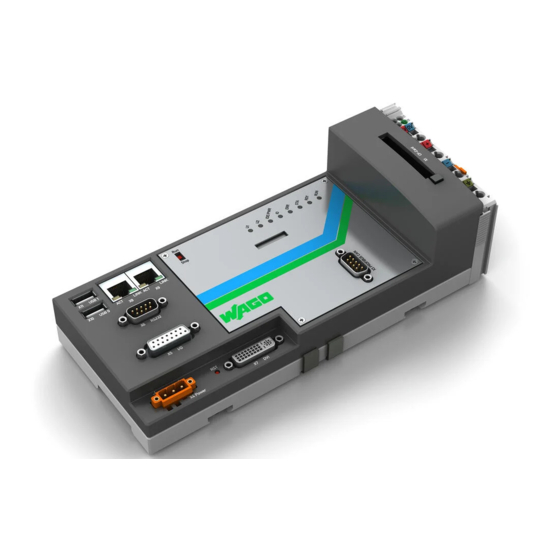
WAGO WAGO-I/O-IPC-C6 Manual (322 pages)
WAGO-I/O-SYSTEM 750
Brand:
WAGO
| Category:
I/O Systems
| Size: 7.29 MB
Table of Contents
Table of Contents
5
Table of Contents
3
1 Notes about this Documentation
10
Validity of These Operating Instructions
10
Copyright
10
Symbols
11
Number Notation
13
Font Conventions
13
Table 1: Number Notation
13
Table 2: Font Conventions
13
2 Important Notes
14
Legal Bases
14
Subject to Changes
14
Personnel Qualification
14
Use in Compliance with Underlying Provisions
15
Technical Condition of Specified Devices
15
Safety Advice (Precautions)
16
Safety Equipment
17
Notes on Operation
17
Special Use Conditions for ETHERNET Devices
17
3 Scope of Delivery
18
4 Device Description
19
Overview of Physical Interfaces
21
Figure 1: Overview of Interfaces
21
Display Elements
23
Figure 2: Leds
23
Operating Elements
24
Figure 3: Operating Elements
24
Battery
26
Figure 4: Battery
26
Labeling
27
Figure 5: Lateral Marking on the I/O-IPC
27
Technical Data
28
Device Data
28
Table 3: Technical Data - Device Data
28
System Data
29
Supply
29
Table 4: Technical Data - System Data
29
Table 5: Technical Data - Supply
29
Communication
30
Protection and Security
30
Runtime System
30
Environmental Requirements
30
Table 6: Technical Data - Communication
30
Table 7: Technical Data - Protection and Security
30
Table 8: Technical Data - Runtime System
30
Table 9: Technical Data - Environmental Requirements
30
Wire Connection
31
Standards and Guidelines
31
Electromagnetic Compatibility
31
Table 10: Technical Data - Wire Connection
31
Table 11: Technical Data - Electromagnetic Compatibility
31
Approvals
32
5 Description of I/O-IPC Interfaces
33
ETHERNET Interfaces (X8, X9)
33
Figure 6: RJ-45 Geode
33
Table 12: ACT/LNK and Speed LED
33
Table 13: ETHERNET Interfaces: Pin Assignments
33
Interface for Electronic Power Supply (X4)
34
Table 14: Interface for Electronic Power Supply: Pin Assignments
34
PROFIBUS Interface (X3)
35
Figure 7: Interface X3
35
Integrated Inputs and Outputs (X5)
36
Table 15: Digital Inputs and Outputs: Pin Assignments
36
Figure 8: Connection of Integrated Inputs
37
Figure 9: Connection of Integrated Outputs
38
USB Interfaces (X10, X11)
39
Figure 10: USB Interface
39
Table 16: USB Interfaces: Pin Assignments
39
Serial Interface (X6)
40
Figure 11: RS-232 Serial Interface
40
Table 17: RS-232 Interface: Pin Assignments
40
DVI-I Interface (X7)
41
Figure 12: DVI-I Interfave
42
Table 18: DVI-I Interface: Pin Assignments
42
6 Installing and Removing the I/O-IPC
43
Instructions for Installation/Removal
43
Accessories Required for Installation
44
Acceptable Mounting Directions for the I/O-IPC
44
Figure 13: Mounting Directions for the I/O-IPC; Recommended Mounting Direction (a 1)
44
Securing the I/O-IPC to a Mounting Rail
45
Figure 14: Securing of the I/O-IPC to a Mounting Rail
45
Connecting the I/O Module to the I/O-IPC
46
Figure 15: Connecting an I/O Module to the I/O-IPC Connecting Clamp
47
Dismounting the I/O-IPC
48
Disconnecting Cables and Conductors
48
Figure 16: I/O-IPC Interfaces
48
Removing the I/O-IPC from the Mounting Rail
49
Figure 17: Removing the I/O-IPC from the Mounting Rail
49
7 Connecting the Supply Voltage
50
Notes
50
Table 19: Use of 750-602/626 Depending on the Application Area of the I/O-IPC
50
Required Accessories
51
Power Supply Via 750-602 Supply Module
52
Figure 18: 750-602
52
Table 20: Connections, Contacts and Supply Module Leds
53
Table 21: Connection for Electronic Supply: Terminal Layout
53
Figure 19: Power Supply Via 750-602 up to HW 10 (with Fieldbus)
54
Figure 20: Power Supply Via 750-602 as of HW 11 (with Fieldbus)
55
Power Supply Via 750-626 Filter Module
56
Table 22: Connection for Electronic Supply: Terminal Layout
56
Figure 21: Power Supply Via 750-626 (with Fieldbus)
57
Connecting Sensor and Actuator Lines to I/O Modules
58
8 Commissioning
59
Turning the I/O-IPC on
59
Determining the IP Address of a Host PC
60
Setting up an IP Address
61
Assigning an IP Address Using Bootp
61
Table 23: Pre-Set IP Addresses for the Ethernet Interfaces
61
Table 24: Net Mask 255.255.255.0
61
Figure 22: Configuration Line in the Configuration File
62
Table 25: Explanations of the Configuration Line
63
Figure 23: Dialog Window of the WAGO Bootp Server with Messages
64
Changing an IP Address Using the Linux Console (IPC Configuration Tool)
65
Figure 24: Start Screen of the WAGO IPC Configuration Tool
65
Figure 25: TCP/IP
65
Figure 26: TCP/IP Configuration Eth0 (X8)
66
Figure 27: IP Address
66
Figure 28: Enter New Address
67
Testing the Network Connection
68
Figure 29: Example of a Functional Test
68
Switch Off/Re-Start
69
Figure 30: Switch Off/Restart of the I/O-IPC
69
9 Configuration
70
Web-Based Management (WBM)
71
Figure 31: Entering the Authentication
71
User Administration of WBM
72
Table 26: User Settings in the Initial State
72
Table 27: Access Rights for WBM Pages
72
Information" Page
73
Figure 32: "Information" Page (Example)
73
Table 28: Description of the Parameters of the "Information" Page
73
Codesys" Page
74
Table 29: Description of the Parameters of the "Codesys" Page
74
TCP/IP" Page
75
Table 30: Description of the Parameters of the "TCP/IP" Page
75
ETHERNET" Page
76
NTP" Page
76
Table 31: Description of the Parameters of the "ETHERNET" Page
76
Table 32: Description of the Parameters of the "NTP" Page
76
Clock" Page
77
Table 33: Description of the Parameters of the "Clock" Page
77
Users" Page
78
Table 34: Description of the Parameters of the "Users" Page
78
HMI Settings" Page
79
Table 35: Description of the Screensaver and Cleanmode Parameters on the "HMI Settings" Page
79
Administration" Page
81
Table 36: Description of the Parameters of the "Administration" Page
82
Package Server" Page
83
Table 37: Description of the Parameters of the "Package Server" Page
83
Mass Storage" Page
85
Downloads" Page
85
Table 38: Description of the Parameters of the "Mass Storage" Page
85
Port" Page
86
MODBUS" Page
86
Table 39: Description of the Parameters of the "MODBUS" Page
86
Page „SNMP
87
Table 40: Description of the Parameters for the "SNMP" Page
87
I/O Configuration
88
Table 41: Description of the Parameters on the "I/O Configuration" Page
88
Webvisu" Page
89
Configuration with a Terminal Program
89
Figure 33: Access to the IPC Configuration Tool Using Telnet
89
Configuration with Touch Screen/Monitor and USB Keyboard
90
Figure 34: Start Screen of the WAGO IPC Configuration Tool
90
10 Modbus/Tcp
91
Table 42: Elements of a MODBUS Telegram
91
Table 43: Basic Data Types of MODBUS
91
Process Data of the MODBUS Server
92
Accessing the Process Image Via MODBUS Functions
92
Table 44: MODBUS Function Codes
92
Register Services
93
Table 45: Reading Analog Input Terminals Using FC3, FC4, FC23
93
Table 46: Writing of Analog Output Terminals Using FC6, FC16, FC23
93
Bit Services
94
Table 47: Reading of Digital Input Terminals Using FC1, FC2
94
Table 48: Writing of Digital Output Terminals Using FC5, FC15
94
Configuration Tab
95
Table 49: Arrangement of the I/O Modules for the Addressing Example
96
Table 50: Addressing Example
96
11 Codesys 2.3 Runtime Environment
97
Process Images
97
Process Image for the I/O Modules Connected to the I/O-IPC
97
Process Image for the Slaves Connected to the I/O-IPC
98
Syntax of Logical Addresses
98
Table 51: Syntax of Logical Addresses
98
Access to the Process Images of the Input and Output Data Via Codesys 2.3
99
Table 52: Memory Areas for the Input and Output Data of Codesys
100
Figure 35: Adaptation of the Remanent Memory Area
101
Addressing Example
102
Table 53: Arrangement of the I/O Modules for the Addressing Example
102
Installing the Programming System Codesys 2.3
103
The First Program with Codesys 2.3
103
Start the Codesys Programming System
103
Table 54: Addressing Example
103
Designing a Project and Selecting the Target System
104
Figure 36: Target Settings (1)
104
Figure 37: Target Settings (2)
104
Figure 38: Designing a New Function Block
105
Figure 39: Programming Interface with the Program Function Block PLC_PRG
105
Creating the PLC Configuration
106
Figure 40: "Resources" Tab
106
Figure 41: PLC Configuration: Appending Sub-Elements
107
Figure 42: I/O Configuration 1
107
Figure 43: I/O Configuration 2
108
Figure 44: PLC Configuration: I/O Module with the Associated Addresses
109
Figure 45: PLC Configuration with Symbolic Names
109
Editing a Program Function Block
110
Figure 46: Program Function Block
110
Figure 47: Input Assistant for Selecting Variables
110
Figure 48: Example of an Assignment
111
Loading and Executing the PLC Program in Control (ETHERNET)
112
Loading and Executing the PLC Program in Control (RS 232)
114
Creating a Boot Project
116
Creating a Task Configuration
117
Figure 49: Changing the Task Name
118
Figure 50: Call to Add Program Function Block
118
Cyclical Task Priorities
119
Figure 51: Changing the Task Name
119
Freewheeling Tasks
120
Figure 52: Freewheeling Tasks
120
System Events
121
Figure 53: System Events
121
Table 55: Events
122
I/O Module Synchronization
123
Case 1: the Codesys Task Interval Is Set as Less than the I/O Module Cycle
123
Figure 54: I/O Module Synchronization 01
123
Case 2: the Codesys Task Interval Is Less than Double the I/O Module Cycle
124
Figure 55: I/O Module Synchronization 02
124
Case 3: the Codesys Task Interval Is Greater than Double the I/O Module Cycle
125
Figure 56: I/O Module Synchronization 03
125
Case 4: Codesys Task Interval Greater than 10 Ms
126
Figure 57: I/O Module Synchronization 04
126
11.10 Codesys Visualization
127
Figure 58: Selection of the Visualization Variants in the Target Setting
127
Figure 59: Generating the PLC_VISU Home Page
128
11.10.1 Incorporating Fonts
129
Table 56: Name Convention for Fonts (Example)
129
11.10.2 Limitations of the Codesys Visualization
130
11.10.3 Eliminating Codesys Web Visualization Errors
132
Table 57: Errors and Its Solution
132
Frequently Asked Questions about Codesys Web Visualization
133
12 PROFIBUS Master in Codesys 2.3
135
PROFIBUS I/O-IPC PLC Configuration
135
Figure 60: Adding the PROFIBUS Master
135
Figure 61: Append PROFIBUS Slaves
136
Figure 62: Selecting I/O Modules
137
Figure 63: DP Parameters
138
PLC Configuration Setting Choices
139
PROFIBUS-Master (I/O-IPC)
139
Figure 64: "Base Parameters" Tab
139
Table 58: Description of the Parameters
139
Figure 65: "DP Parameters" Tab
140
Table 59: Description of the Parameters
140
Figure 66: "Bus Parameters" Tab
141
Table 60: Description of the Parameters
141
Figure 67: "Module Parameters" Tab (Example)
142
Table 61: Description of the Parameters
142
Figure 68: Target System Settings
143
PROFIBUS Slaves
144
Figure 69: "Base Parameters" Tab
144
Table 62: Description of the Parameters
144
Figure 70: "DP Parameters" Tab
145
Table 63: Description of the Parameters
145
Figure 71: "Input/Output" Tab
146
Table 64: Description of the Parameters
146
Figure 72: "User Parameters" Tab (Example)
147
Table 65: Description of the Parameters
147
Figure 73: "Groups" Tab
148
Table 66: Description of the Parameters
148
Access to the PROFIBUS Process Data
149
Figure 74: PLC Configuration: I/O Modules with Their Associated Addresses
149
Figure 76: Input Assistant for Selecting Variables
150
Loading the Program in the I/O-IPC
151
Figure 77: Example of an Assignment of the Previously Created Variables
151
Diagnostics of the Fieldbus Coupler
152
Releasing the Channel Diagnostics
152
Figure 78: Release of Channel Diagnostics 1
152
Figure 79: Release of Channel Diagnostics 2
153
Diaggetbusstate() and Diaggetstate()
154
Creation of Diagnostic Functions in Codesys 2.3
155
Figure 80: "Resources" Tab
155
Figure 81: "Open" Dialog
156
Figure 82: Box Symbol in the Menu List, FBD Programming Language
156
Figure 83: Instance of the Function Block Diaggetbusstate() in FBD
156
Calling the Diagnostic Block
157
Figure 84: Function Block Diaggetstate() in FBD
157
Figure 85: Offline View of the Variable Window in Codesys
157
Performing Bus Diagnostics Via Diaggetbusstate()
158
Figure 86: Online View of the Variable Window (Upper Window) in FBD
158
Figure 87: Example of Diagnostics
159
Table 67: Bits of the Diagnostics Information
159
Performing Device Diagnostics Via Diaggetstate()
160
Analyzing PROFIBUS Diagnostics of Individual I/O Modules
160
Figure 88: Diagnostics Call Diaggetstate()
160
Figure 89: Online View of the Array EXTENDEDINFO in the Binary Representation
161
Figure 90: Online View of the Arrays EXTENDEDINFO in Binary Representation 1
164
Figure 91: Online View of the Arrays EXTENDEDINFO in Binary Representation 2
165
13 Incorporation of C-Functions as Codesys Library
166
Example for Linking a Dynamic Library
166
Developing and Compiling a Linux Shared Library
166
Figure 92: "Libmytest.C" File
166
Creating a Description File for the Codesys Runtime System
167
Figure 93: "Extlibs.ini" File
167
Figure 94: "Extlibs.ini" File
167
Copying a Library and INI File and Restarting the Codesys Runtime System
168
Creating an IEC Library
169
Figure 95: "Target Settings" Window
169
Figure 96: "New POU" Window
169
Figure 97: "Mytestfunction" Window
170
Figure 98: "Save File As" Window
170
Linking a Library to the Codesys Project
171
Figure 75: PLC_PRG
173
Special Features
174
Data Types
174
Table 68: Data Types
174
Structures
175
Figure 99: "Example.lib" File
175
Figure 100: "Example.h" File
175
Parameter Transfer by Reference or by Value
176
Additional Applications
176
14 Operating System
177
Linux Kernel Used
177
Grand Unified Bootloader (GRUB)
178
Figure 101: Serial Console "Hyperterminal
178
Linux Startup Process
179
Linux Console
180
Access to the Linux Console
180
Table 69: Users for the Linux Console
180
Access over Telnet
182
Figure 102: DOS Console 1
182
Figure 103: DOS Console 2
182
Access Via RS-232 Interface and Terminal Program
183
Figure 104: RS-232 Interface X6
183
Access over Keyboard and Monitor (DVI-I and USB Interface)
184
Figure 105: DVI-I Interface X7 and USB Interfaces X10/11
184
Installed Applications
185
Construction of the File System
186
Table 70: Construction of the File System
186
Installed Shell (BASH)
189
Busybox and Other Help Programs
189
Drivers for Special Hardware Parts
191
Incorporation of a USB Printer
191
Installed Services of the ETHERNET Interface
192
Telnet Server (Telnetd)
192
FTP Server (Pure-Ftpd)
193
Figure 106: DOS Console
193
NFS Server
194
FTP Client
194
Web Server (Lighttp)
195
NTP Client
195
NFS Client
196
SNMP Agent
196
15 Diagnostics
198
Operational Messages
198
Figure 107: Identification of Leds
198
Table 71: I/O-IPC Operational Messages
198
Table 72: I/O-IPC Operational Messages
200
Table 73: I/O-IPC Operational Messages
201
Table 74: Operating Reports of ERR and STA LED
202
Error Messages Via I/O-LED
203
Figure 108: Display of Blink Codes by the I/O-LED
203
Progression of Blink Sequence
204
Figure 109: Blink Sequence Process Diagram
204
Example of an Error Message Via Blink Code
205
Meaning of the Blink Codes and Procedures for Troubleshooting
206
Table 75: Meaning of Blink Codes and Measures to Eliminate Errors
206
16 Service
211
Replacing the Battery
211
Figure 110: Changing the Battery for the Emergency Power Supply 1
212
Figure 111: Changing the Battery for the Emergency Power Supply 2
212
Disposal
213
17 Use in Hazardous Environments
214
Marking Configuration Examples
215
Marking for Europe According to CENELEC and IEC
215
Figure 112: Side Marking Example for ATEX and IEC Ex Approved I/O Modules According to CENELEC and IEC
215
Figure 113: Printing Text Detail - Marking Example for ATEX and IEC Ex Approved I/O Modules According to CENELEC and IEC
215
Table 76: Description of Marking Example for ATEX and IEC Ex Approved I/O Modules According to CENELEC and IEC
215
Figure 114: Side Marking Example for Ex I and IEC Ex I Approved I/O Modules According to CENELEC and IEC
216
Figure 115: Text Detail - Marking Example for Ex I and IEC Ex I Approved I/O Modules According to CENELEC and IEC
216
Table 77: Description of Marking Example for Ex I and IEC Ex I Approved I/O Modules According to CENELEC and IEC
217
Marking for America According to NEC 500
218
Figure 116: Side Marking Example for I/O Modules According to NEC 500
218
Figure 117: Text Detail - Marking Example for I/O Modules According to NEC 500
218
Table 78: Description of Marking Example for I/O Modules According to NEC 500
218
Installation Regulations
219
Table 79: VDE Installation Regulations in Germany
219
Table 80: Installation Regulations in USA and Canada
219
Special Conditions for Safe Use (ATEX Certificate TÜV 07 ATEX 554086 X)
220
Special Conditions for Safe Use (IEC-Ex Certificate TUN 09.0001 X)
222
18 I/O Modules
224
Overview
224
Process Data Architecture for MODBUS/TCP
225
Digital Input Modules
226
Channel Digital Input Module with Diagnostics
226
Channel Digital Input Modules
226
Table 81: 1 Channel Digital Input Module with Diagnostics
226
Table 82: 2 Channel Digital Input Modules
226
Table 83: 2 Channel Digital Input Module with Diagnostics
226
Channel Digital Input Module with Diagnostics and Output Process Data
227
Channel Digital Input Modules
227
Table 84: 2 Channel Digital Input Module with Diagnostics and Output Process Data
227
Table 85: 4 Channel Digital Input Modules
227
Table 86: 8 Channel Digital Input Modules
227
16 Channel Digital Input Modules
228
Table 87: 16 Channel Digital Input Modules
228
Digital Output Modules
229
Channel Digital Output Module with Input Process Data
229
Channel Digital Output Modules
229
Table 88: 1 Channel Digital Output Module with Input Process Data
229
Table 89: 2 Channel Digital Output Modules
229
Channel Digital Input Modules with Diagnostics and Input Process Data
230
Table 90: 2 Channel Digital Input Modules with Diagnostics and Input Process Data
230
Table 91: 2 Channel Digital Input Modules with Diagnostics and Input Process Data 75X-506
230
Channel Digital Output Modules
231
Channel Digital Output Modules with Diagnostics and Input Process Data
231
Channel Digital Output Module
231
Table 92: 4 Channel Digital Output Modules
231
Table 93: 4 Channel Digital Output Modules with Diagnostics and Input Process Data
231
Table 94: 8 Channel Digital Output Module
231
Channel Digital Output Modules with Diagnostics and Input Process Data
232
16 Channel Digital Output Modules
232
Table 95: 8 Channel Digital Output Modules with Diagnostics and Input Process Data
232
Table 96: 16 Channel Digital Output Modules
232
Channel Digital Input/Output Modules
233
Table 97: 8 Channel Digital Input/Output Modules
233
Analog Input Modules
234
Channel Analog Input Modules
234
Table 98: 1 Channel Analog Input Modules
234
Table 99: 2 Channel Analog Input Modules
234
Channel Analog Input Modules
235
Table 100: 4 Channel Analog Input Modules
235
Analog Output Modules
236
Channel Analog Output Modules
236
Table 101: 2 Channel Analog Output Modules
236
Table 102: 4 Channel Analog Output Modules
236
Specialty Modules
237
Counter Modules
237
Table 103: Counter Modules 750-404, (and All Variations Except of /000-005), 753-404, (and Variation /000-003)
237
Table 104: Counter Modules 750-404/000-005
238
Table 105: Counter Modules 750-638, 753-638
238
Pulse Width Modules
239
Serial Interface Modules with Alternative Data Format
239
Table 106: Pulse Width Modules 750-511, /XXX-XXX
239
Table 107: Serial Interface Modules with Alternative Data Format
239
Serial Interface Modules with Standard Data Format
240
Data Exchange Module
240
SSI Transmitter Interface Modules
240
Table 108: Serial Interface Modules with Standard Data Format
240
Table 109: Data Exchange Module
240
Incremental Encoder Interface Modules
241
Table 110: SSI Transmitter Interface Modules
241
Table 112: Incremental Encoder Interface Modules 750-634
242
Table 113: Incremental Encoder Interface Modules 750-637
242
DC-Drive Controller
243
Table 114: Digital Pulse Interface Modules 750-635
243
Table 115: DC-Drive Controller 750-636
243
Stepper Controller
244
Table 116: Stepper Controller RS 422 / 24 V / 20 Ma 750-670
244
18.2.5.10 RTC Module
245
18.2.5.11 DALI/DSI Master Module
245
Table 117: RTC Module 750-640
245
Table 118: DALI/DSI Master Module 750-641
245
18.2.5.12 Enocean Radio Receiver
246
18.2.5.13 MP Bus Master Module
246
Table 119: Enocean Radio Receiver 750-642
246
Table 120: MP Bus Master Module 750-643
246
RF-Transceiver
247
Table 121: Bluetooth ® RF-Transceiver 750-644
247
18.2.5.15 Vibration Velocity/Bearing Condition Monitoring VIB I/O
248
18.2.5.16 KNX/EIB/TP1 Module
248
Table 122: Vibration Velocity/Bearing Condition Monitoring VIB I/O
248
18.2.5.17 AS-Interface Master Module
249
Table 123: KNX/EIB/TP1 Module 753-646
249
Table 124: AS-Interface Master Module 750-655
250
System Modules
251
System Modules with Diagnostics
251
Binary Space Module
251
Table 125: System Modules with Diagnostics 750-610, -611
251
Table 126: Binary Space Module
251
Mailbox Modules
252
19 Appendix
253
Wagoconfigtoollib.lib
253
Figure 118: Graphical Representation of the "Configtool" Function Block
253
Table 127: "Configtool" Function Block
253
Table 128: Function STRING_TO_IP
254
Table 129: Function IP_TO_STRING
254
Calls for the "Wagoconfigtoollib.lib" Library
255
Figure 119: Graphical Representation of the "Configtool" Function Block
255
Table 130: Description of the Configuration Scripts for "Information
255
Table 131: Description of the Configuration Scripts for "Codesys
256
Table 132: Description of the Configuration Scripts for "TCP/IP
256
Table 133: Description of the Configuration Scripts for "ETHERNET
259
Table 134: Description of the Configuration Scripts for "NTP
260
Table 135: Description of the Configuration Scripts for "Clock
261
Table 136: Description of the Configuration Scripts for "HMI Settings
262
Table 137: Description of the Configuration Scripts for "Administration
265
Table 138: Description of the Configuration Scripts for "Package Server
267
Table 139: Description of the Configuration Scripts for "Mass Storage
267
Table 140: Description of the Configuration Scripts for "Port
268
Table 141: Description of the Configuration Scripts for "MODBUS
269
Table 142: Description of the Configuration Scripts for " General SNMP Information Parameters
271
Wagolibnetsnmp.lib
275
Snmpregistercustomoid_Int32()
276
Table 143: Data Type
276
Table 144: Parameter Snmpregistercustomoid_Int32()
276
Table 145: Return Snmpregistercustomoid_Int32()
276
Snmpregistercustomoid_String()
277
Table 146: Parameter Snmpregistercustomoid_String()
277
Table 147: Return Snmpregistercustomoid_String()
277
Snmpregistercustomoid_Uint32()
278
Table 148: Parameter Snmpregistercustomoid_Uint32()
278
Table 149: Return Snmpregistercustomoid_Uint32()
278
Snmpgetvaluecustomoid_Int32()
279
Table 150: Parameter Snmpgetvaluecustomoid_Int32()
279
Table 151: Return Snmpgetvaluecustomoid_Int32()
279
Snmpgetvaluecustomoid_String()
280
Table 152: Parameter Snmpgetvaluecustomoid_String()
280
Table 153: Return Snmpgetvaluecustomoid_String()
280
Snmpgetvaluecustomoid_Uint32()
281
Table 154: Parameter Snmpgetvaluecustomoid_Int32()
281
Table 155: Return Snmpgetvaluecustomoid_Int32()
281
Snmpsetvaluecustomoid_Int32()
282
Table 156: Parameter Snmpsetvaluecustomoid_Int32()
282
Table 157: Return Snmpsetvaluecustomoid_Int32()
282
Snmpsetvaluecustomoid_String()
283
Table 158: Parameter Snmpsetvaluecustomoid_String()
283
Table 159: Return Snmpsetvaluecustomoid_String()
283
Snmpsetvaluecustomoid_Uint32()
284
Table 160: Parameter Snmpsetvaluecustomoid_Uint32()
284
Table 161: Return Snmpsetvaluecustomoid_Uint32()
284
19.2.10 Feedback
285
Table 162: Error Messages
285
19.2.11 Example Program "Test.pro
286
Wago_Dpm_01.Lib
289
Dpm_Version
290
Dpm_Redundancy
291
Dpm_Global_Control
293
Dpm_Read_Input
295
W Dpm_Read_Output
297
Dpm_Set_Slave_Address
299
Dpm_Msac1_Read
301
Dpm_Msac1_Write
303
Dpm_Msac1_Error
305
Function_Code
306
Dpm_Error_Class
307
App_Code
308
Acc_Code
309
19.3.14 Res_Code
310
Dpm_Control
311
Mode_Indication
312
Mod_Com.lib
313
Sercomm.lib
313
Wagolibterminaldiag.lib
313
Syslibcom.lib
313
Syslibfile, Syslibdir, Syslibfileasync
314
Figure 120: Formatting Partname
314
Advertisement
WAGO WAGO-I/O-IPC-C6 Manual (258 pages)
WAGO-I/O-SYSTEM 750
Brand:
WAGO
| Category:
I/O Systems
| Size: 5.76 MB
Table of Contents
Table of Contents
5
Table of Contents
3
1 Notes about this Documentation
9
Validity of These Operating Instructions
9
Copyright
9
Symbols
10
Number Notation
12
Font Conventions
12
Table 1: Number Notation
12
Table 2: Font Conventions
12
2 Important Notes
13
Legal Bases
13
Subject to Changes
13
Personnel Qualification
13
Use in Compliance with Underlying Provisions
14
Technical Condition of Specified Devices
14
Safety Advice (Precautions)
15
Safety Equipment
16
Notes on Operation
16
Special Use Conditions for ETHERNET Devices
16
3 Scope of Delivery
17
4 Device Description
18
Overview of Physical Interfaces
19
Figure 1: Overview of Interfaces
19
Display Elements
20
Figure 2: Leds
20
Operating Elements
21
Figure 3: Operating Elements
21
Battery
22
Figure 4: Battery
22
Labeling
23
Figure 5: Lateral Marking on the I/O-IPC
23
Technical Data
24
Device Data
24
Table 3: Technical Data - Device Data
24
System Data
25
Supply
25
Table 4: Technical Data - System Data
25
Table 5: Technical Data - Supply
25
Communication
26
Protection and Security
26
Runtime System
26
Environmental Requirements
26
Table 6: Technical Data - Communication
26
Table 7: Technical Data - Protection and Security
26
Table 8: Technical Data - Runtime System
26
Table 9: Technical Data - Environmental Requirements
26
Wire Connection
27
Standards and Guidelines
27
Electromagnetic Compatibility
27
Table 10: Technical Data - Wire Connection
27
Table 11: Technical Data - Electromagnetic Compatibility
27
Approvals
28
5 Description of I/O-IPC Interfaces
29
ETHERNET Interfaces (X8, X9)
29
Figure 6: RJ-45 Geode
29
Table 12: ACT/LNK and Speed LED
29
Table 13: ETHERNET Interfaces: Pin Assignments
29
Interface for Electronic Power Supply (X4)
30
Table 14: Interface for Electronic Power Supply: Pin Assignments
30
Integrated Inputs and Outputs (X5)
31
Table 15: Digital Inputs and Outputs: Pin Assignments
31
Figure 7: Connection of Integrated Inputs
32
Figure 8: Connection of Integrated Outputs
33
USB Interfaces (X10, X11)
34
Figure 9: USB Interface
34
Table 16: USB Interfaces: Pin Assignments
34
Serial Interface (X6)
35
Figure 10: RS-232 Serial Interface
35
Table 17: RS-232 Interface: Pin Assignments
35
DVI-I Interface (X7)
36
Figure 11: DVI-I Interfave
37
Table 18: DVI-I Interface: Pin Assignments
37
6 Installing and Removing the I/O-IPC
38
Instructions for Installation/Removal
38
Accessories Required for Installation
39
Acceptable Mounting Directions for the I/O-IPC
39
Figure 12: Mounting Directions for the I/O-IPC; Recommended Mounting Direction (a 1)
39
Securing the I/O-IPC to a Mounting Rail
40
Figure 13: Securing of the I/O-IPC to a Mounting Rail
40
Connecting the I/O Module to the I/O-IPC
41
Figure 14: Connecting an I/O Module to the I/O-IPC Connecting Clamp
42
Dismounting the I/O-IPC
43
Disconnecting Cables and Conductors
43
Figure 15: I/O-IPC Interfaces
43
Removing the I/O-IPC from the Mounting Rail
44
Figure 16: Removing the I/O-IPC from the Mounting Rail
44
7 Connecting the Supply Voltage
45
Notes
45
Table 19: Use of 750-602/626 Depending on the Application Area of the I/O-IPC
45
Required Accessories
46
Power Supply Via 750-602 Supply Module
47
Figure 17: 750-602
47
Table 20: Connections, Contacts and Supply Module Leds
48
Table 21: Connection for Electronic Supply: Terminal Layout
48
Figure 18: Power Supply Via 750-602 up to HW 10 (Without Fieldbus)
49
Figure 19: Power Supply Via 750-602 as of HW 11 (Without Fieldbus)
50
Power Supply Via 750-626 Filter Module
51
Table 22: Connection for Electronic Supply: Terminal Layout
51
Figure 20: Power Supply Via 750-626 (Without_Fieldbus)
52
Connecting Sensor and Actuator Lines to I/O Modules
53
8 Commissioning
54
Turning the I/O-IPC on
54
Determining the IP Address of a Host PC
55
Setting up an IP Address
56
Assigning an IP Address Using Bootp
56
Table 23: Pre-Set IP Addresses for the Ethernet Interfaces
56
Table 24: Net Mask 255.255.255.0
56
Figure 21: Configuration Line in the Configuration File
57
Table 25: Explanations of the Configuration Line
58
Figure 22: Dialog Window of the WAGO Bootp Server with Messages
59
Changing an IP Address Using the Linux Console (IPC Configuration Tool)
60
Figure 23: Start Screen of the WAGO IPC Configuration Tool
60
Figure 24: TCP/IP
60
Figure 25: TCP/IP Configuration Eth0 (X8)
61
Figure 26: IP Address
61
Figure 27: Enter New Address
62
Testing the Network Connection
63
Figure 28: Example of a Functional Test
63
Switch Off/Re-Start
64
Figure 29: Switch Off/Restart of the I/O-IPC
64
9 Configuration
65
Web-Based Management (WBM)
66
Figure 30: Entering the Authentication
66
User Administration of WBM
67
Table 26: User Settings in the Initial State
67
Table 27: Access Rights for WBM Pages
67
Information" Page
68
Figure 31: "Information" Page (Example)
68
Table 28: Description of the Parameters of the "Information" Page
68
Codesys" Page
69
Table 29: Description of the Parameters of the "Codesys" Page
69
TCP/IP" Page
70
Table 30: Description of the Parameters of the "TCP/IP" Page
70
ETHERNET" Page
71
NTP" Page
71
Table 31: Description of the Parameters of the "ETHERNET" Page
71
Table 32: Description of the Parameters of the "NTP" Page
71
Clock" Page
72
Table 33: Description of the Parameters of the "Clock" Page
72
Users" Page
73
Table 34: Description of the Parameters of the "Users" Page
73
HMI Settings" Page
74
Table 35: Description of the Screensaver and Cleanmode Parameters on the "HMI Settings" Page
74
Administration" Page
76
Table 36: Description of the Parameters of the "Administration" Page
77
Package Server" Page
78
Table 37: Description of the Parameters of the "Package Server" Page
78
Mass Storage" Page
80
Downloads" Page
80
Table 38: Description of the Parameters of the "Mass Storage" Page
80
Port" Page
81
MODBUS" Page
81
Table 39: Description of the Parameters of the "MODBUS" Page
81
Page „SNMP
82
Table 40: Description of the Parameters for the "SNMP" Page
82
I/O Configuration
83
Table 41: Description of the Parameters on the "I/O Configuration" Page
83
Webvisu" Page
84
Configuration with a Terminal Program
84
Figure 32: Access to the IPC Configuration Tool Using Telnet
84
Configuration with Touch Screen/Monitor and USB Keyboard
85
Figure 33: Start Screen of the WAGO IPC Configuration Tool
85
10 Modbus/Tcp
86
Table 42: Elements of a MODBUS Telegram
86
Table 43: Basic Data Types of MODBUS
86
Process Data of the MODBUS Server
87
Accessing the Process Image Via MODBUS Functions
87
Table 44: MODBUS Function Codes
87
Register Services
88
Table 45: Reading Analog Input Terminals Using FC3, FC4, FC23
88
Table 46: Writing of Analog Output Terminals Using FC6, FC16, FC23
88
Bit Services
89
Table 47: Reading of Digital Input Terminals Using FC1, FC2
89
Table 48: Writing of Digital Output Terminals Using FC5, FC15
89
Configuration Tab
90
Table 49: Arrangement of the I/O Modules for the Addressing Example
91
Table 50: Addressing Example
91
11 Codesys 2.3 Runtime Environment
92
Syntax of Logical Addresses
92
Table 51: Syntax of Logical Addresses
92
Access to the Process Images of the Input and Output Data Via Codesys 2.3
93
Table 52: Memory Areas for the Input and Output Data of Codesys
94
Figure 34: Adaptation of the Remanent Memory Area
95
Addressing Example
96
Table 53: Arrangement of the I/O Modules for the Addressing Example
96
Installing the Programming System Codesys 2.3
97
The First Program with Codesys 2.3
97
Start the Codesys Programming System
97
Table 54: Addressing Example
97
Designing a Project and Selecting the Target System
98
Figure 35: Target Settings (1)
98
Figure 36: Target Settings (2)
98
Figure 37: Designing a New Function Block
99
Figure 38: Programming Interface with the Program Function Block PLC_PRG
99
Creating the PLC Configuration
100
Figure 39: "Resources" Tab
100
Figure 40: PLC Configuration: Appending Sub-Elements
101
Figure 41: I/O Configuration 1
101
Figure 42: I/O Configuration 2
102
Figure 43: PLC Configuration: I/O Module with the Associated Addresses
103
Figure 44: PLC Configuration with Symbolic Names
103
Editing a Program Function Block
104
Figure 45: Program Function Block
104
Figure 46: Input Assistant for Selecting Variables
104
Figure 47: Example of an Assignment
105
Loading and Executing the PLC Program in Control (ETHERNET)
106
Loading and Executing the PLC Program in Control (RS 232)
108
Creating a Boot Project
110
Creating a Task Configuration
111
Figure 48: Changing the Task Name
112
Figure 49: Call to Add Program Function Block
112
Cyclical Task Priorities
113
Figure 50: Changing the Task Name
113
Freewheeling Tasks
114
Figure 51: Freewheeling Tasks
114
System Events
115
Figure 52: System Events
115
Table 55: Events
116
I/O Module Synchronization
117
Case 1: the Codesys Task Interval Is Set as Less than the I/O Module Cycle
117
Figure 53: I/O Module Synchronization 01
117
Case 2: the Codesys Task Interval Is Less than Double the I/O Module Cycle
118
Figure 54: I/O Module Synchronization 02
118
Case 3: the Codesys Task Interval Is Greater than Double the I/O Module Cycle
119
Figure 55: I/O Module Synchronization 03
119
Case 4: Codesys Task Interval Greater than 10 Ms
120
Figure 56: I/O Module Synchronization 04
120
Codesys Visualization
121
Figure 57: Selection of the Visualization Variants in the Target Setting
121
Figure 58: Generating the PLC_VISU Home Page
122
Incorporating Fonts
123
Table 56: Name Convention for Fonts (Example)
123
Limitations of the Codesys Visualization
124
Eliminating Codesys Web Visualization Errors
126
Table 57: Errors and Its Solution
126
Frequently Asked Questions about Codesys Web Visualization
127
12 Incorporation of C-Functions as Codesys Library
129
Example for Linking a Dynamic Library
129
Developing and Compiling a Linux Shared Library
129
Figure 59: "Libmytest.C" File
129
Creating a Description File for the Codesys Runtime System
130
Figure 60: "Extlibs.ini" File
130
Figure 61: "Extlibs.ini" File
130
Copying a Library and INI File and Restarting the Codesys Runtime System
131
Creating an IEC Library
132
Figure 62: "Target Settings" Window
132
Figure 63: "New POU" Window
132
Figure 64: "Mytestfunction" Window
133
Figure 65: "Save File As" Window
133
Linking a Library to the Codesys Project
134
Special Features
137
Data Types
137
Table 58: Data Types
137
Structures
138
Figure 66: "Example.lib" File
138
Figure 67: "Example.h" File
138
Parameter Transfer by Reference or by Value
139
Additional Applications
139
13 Operating System
140
Linux Kernel Used
140
Grand Unified Bootloader (GRUB)
141
Figure 68: Serial Console "Hyperterminal
141
Linux Startup Process
142
Linux Console
143
Access to the Linux Console
143
Table 59: Users for the Linux Console
143
Access over Telnet
145
Figure 69: DOS Console 1
145
Figure 70: DOS Console 2
145
Access Via RS-232 Interface and Terminal Program
146
Figure 71: RS-232 Interface X6
146
Access over Keyboard and Monitor (DVI-I and USB Interface)
147
Figure 72: DVI-I Interface X7 and USB Interfaces X10/11
147
Installed Applications
148
Construction of the File System
149
Table 60: Construction of the File System
149
Installed Shell (BASH)
152
Busybox and Other Help Programs
152
Drivers for Special Hardware Parts
154
Incorporation of a USB Printer
154
Installed Services of the ETHERNET Interface
155
Telnet Server (Telnetd)
155
FTP Server (Pure-Ftpd)
156
Figure 73: DOS Console
156
NFS Server
157
FTP Client
157
Web Server (Lighttp)
158
NTP Client
158
NFS Client
159
SNMP Agent
159
14 Diagnostics
161
Operational Messages
161
Figure 74: Identification of Leds
161
Table 61: I/O-IPC Operational Messages
161
Table 62: I/O-IPC Operational Messages
163
Table 63: Operating Reports of ERR and STA LED
163
Error Messages Via I/O-LED
164
Figure 75: Display of Blink Codes by the I/O-LED
164
Progression of Blink Sequence
165
Figure 76: Blink Sequence Process Diagram
165
Example of an Error Message Via Blink Code
166
Meaning of the Blink Codes and Procedures for Troubleshooting
167
Table 64: Meaning of Blink Codes and Measures to Eliminate Errors
167
15 Service
172
Replacing the Battery
172
Figure 77: Changing the Battery for the Emergency Power Supply 1
173
Figure 78: Changing the Battery for the Emergency Power Supply 2
173
Disposal
174
16 Use in Hazardous Environments
175
Marking Configuration Examples
176
Marking for Europe According to CENELEC and IEC
176
Figure 79: Side Marking Example for ATEX and IEC Ex Approved I/O Modules According to CENELEC and IEC
176
Figure 80: Printing Text Detail - Marking Example for ATEX and IEC Ex Approved I/O Modules According to CENELEC and IEC
176
Table 65: Description of Marking Example for ATEX and IEC Ex Approved I/O Modules According to CENELEC and IEC
176
Figure 81: Side Marking Example for Ex I and IEC Ex I Approved I/O Modules According to CENELEC and IEC
177
Figure 82: Text Detail - Marking Example for Ex I and IEC Ex I Approved I/O Modules According to CENELEC and IEC
177
Table 66: Description of Marking Example for Ex I and IEC Ex I Approved I/O Modules According to CENELEC and IEC
178
Marking for America According to NEC 500
179
Figure 83: Side Marking Example for I/O Modules According to NEC 500
179
Figure 84: Text Detail - Marking Example for I/O Modules According to NEC 500
179
Table 67: Description of Marking Example for I/O Modules According to NEC 500
179
Installation Regulations
180
Table 68: VDE Installation Regulations in Germany
180
Table 69: Installation Regulations in USA and Canada
180
Special Conditions for Safe Use (ATEX Certificate TÜV 07 ATEX 554086 X)
181
Special Conditions for Safe Use (IEC-Ex Certificate TUN 09.0001 X)
183
17 I/O Modules
185
Overview
185
Process Data Architecture for MODBUS/TCP
186
Digital Input Modules
187
Channel Digital Input Module with Diagnostics
187
Channel Digital Input Modules
187
Table 70: 1 Channel Digital Input Module with Diagnostics
187
Table 71: 2 Channel Digital Input Modules
187
Table 72: 2 Channel Digital Input Module with Diagnostics
187
Channel Digital Input Module with Diagnostics and Output Process Data
188
Channel Digital Input Modules
188
Table 73: 2 Channel Digital Input Module with Diagnostics and Output Process Data
188
Table 74: 4 Channel Digital Input Modules
188
Table 75: 8 Channel Digital Input Modules
188
16 Channel Digital Input Modules
189
Table 76: 16 Channel Digital Input Modules
189
Digital Output Modules
190
Channel Digital Output Module with Input Process Data
190
Channel Digital Output Modules
190
Table 77: 1 Channel Digital Output Module with Input Process Data
190
Table 78: 2 Channel Digital Output Modules
190
Channel Digital Input Modules with Diagnostics and Input Process Data
191
Table 79: 2 Channel Digital Input Modules with Diagnostics and Input Process Data
191
Table 80: 2 Channel Digital Input Modules with Diagnostics and Input Process Data 75X-506
191
Channel Digital Output Modules
192
Channel Digital Output Modules with Diagnostics and Input Process Data
192
Channel Digital Output Module
192
Table 81: 4 Channel Digital Output Modules
192
Table 82: 4 Channel Digital Output Modules with Diagnostics and Input Process Data
192
Table 83: 8 Channel Digital Output Module
192
Channel Digital Output Modules with Diagnostics and Input Process Data
193
Channel Digital Output Modules
193
Table 84: 8 Channel Digital Output Modules with Diagnostics and Input Process Data
193
Table 85: 16 Channel Digital Output Modules
193
Channel Digital Input/Output Modules
194
Table 86: 8 Channel Digital Input/Output Modules
194
Analog Input Modules
195
Channel Analog Input Modules
195
Table 87: 1 Channel Analog Input Modules
195
Table 88: 2 Channel Analog Input Modules
195
Channel Analog Input Modules
196
Table 89: 4 Channel Analog Input Modules
196
Analog Output Modules
197
Channel Analog Output Modules
197
Table 90: 2 Channel Analog Output Modules
197
Table 91: 4 Channel Analog Output Modules
197
Specialty Modules
198
Counter Modules
198
Table 92: Counter Modules 750-404, (and All Variations Except of /000-005), 753-404, (and Variation /000-003)
198
Table 93: Counter Modules 750-404/000-005
199
Table 94: Counter Modules 750-638, 753-638
199
Pulse Width Modules
200
Serial Interface Modules with Alternative Data Format
200
Table 95: Pulse Width Modules 750-511, /XXX-XXX
200
Table 96: Serial Interface Modules with Alternative Data Format
200
Serial Interface Modules with Standard Data Format
201
Data Exchange Module
201
SSI Transmitter Interface Modules
201
Table 97: Serial Interface Modules with Standard Data Format
201
Table 98: Data Exchange Module
201
Incremental Encoder Interface Modules
202
Table 99: SSI Transmitter Interface Modules
202
Table 101: Incremental Encoder Interface Modules 750-634
203
Table 102: Incremental Encoder Interface Modules 750-637
203
DC-Drive Controller
204
Table 103: Digital Pulse Interface Modules 750-635
204
Table 104: DC-Drive Controller 750-636
204
Stepper Controller
205
Table 105: Stepper Controller RS 422 / 24 V / 20 Ma 750-670
205
17.2.5.10 RTC Module
206
17.2.5.11 DALI/DSI Master Module
206
Table 106: RTC Module 750-640
206
Table 107: DALI/DSI Master Module 750-641
206
17.2.5.12 Enocean Radio Receiver
207
17.2.5.13 MP Bus Master Module
207
Table 108: Enocean Radio Receiver 750-642
207
Table 109: MP Bus Master Module 750-643
207
Bluetooth ® RF-Transceiver
208
Table 110: Bluetooth ® RF-Transceiver 750-644
208
17.2.5.15 Vibration Velocity/Bearing Condition Monitoring VIB I/O
209
17.2.5.16 KNX/EIB/TP1 Module
209
Table 111: Vibration Velocity/Bearing Condition Monitoring VIB I/O
209
17.2.5.17 AS-Interface Master Module
210
Table 112: KNX/EIB/TP1 Module 753-646
210
Table 113: AS-Interface Master Module 750-655
211
System Modules
212
System Modules with Diagnostics
212
Binary Space Module
212
Table 114: System Modules with Diagnostics 750-610, -611
212
Table 115: Binary Space Module
212
Mailbox Modules
213
18 Appendix
214
Wagoconfigtoollib.lib
214
Figure 85: Graphical Representation of the "Configtool" Function Block
214
Table 116: "Configtool" Function Block
214
Table 117: Function STRING_TO_IP
215
Table 118: Function IP_TO_STRING
215
Calls for the "Wagoconfigtoollib.lib" Library
216
Figure 86: Graphical Representation of the "Configtool" Function Block
216
Table 119: Description of the Configuration Scripts for "Information
216
Table 120: Description of the Configuration Scripts for "Codesys
217
Table 121: Description of the Configuration Scripts for "TCP/IP
217
Table 122: Description of the Configuration Scripts for "ETHERNET
220
Table 123: Description of the Configuration Scripts for "NTP
221
Table 124: Description of the Configuration Scripts for "Clock
222
Table 125: Description of the Configuration Scripts for "HMI Settings
223
Table 126: Description of the Configuration Scripts for "Administration
227
Table 127: Description of the Configuration Scripts for "Package Server
228
Table 128: Description of the Configuration Scripts for "Mass Storage
228
Table 129: Description of the Configuration Scripts for "Port
229
Table 130: Description of the Configuration Scripts for "MODBUS
230
Table 131: Description of the Configuration Scripts for " General SNMP Information Parameters
232
Wagolibnetsnmp.lib
236
Snmpregistercustomoid_Int32()
237
Table 132: Data Type
237
Table 133: Parameter Snmpregistercustomoid_Int32()
237
Table 134: Return Snmpregistercustomoid_Int32()
237
Snmpregistercustomoid_String()
238
Table 135: Parameter Snmpregistercustomoid_String()
238
Table 136: Return Snmpregistercustomoid_String()
238
Snmpregistercustomoid_Uint32()
239
Table 137: Parameter Snmpregistercustomoid_Uint32()
239
Table 138: Return Snmpregistercustomoid_Uint32()
239
Snmpgetvaluecustomoid_Int32()
240
Table 139: Parameter Snmpgetvaluecustomoid_Int32()
240
Table 140: Return Snmpgetvaluecustomoid_Int32()
240
Snmpgetvaluecustomoid_String()
241
Table 141: Parameter Snmpgetvaluecustomoid_String()
241
Table 142: Return Snmpgetvaluecustomoid_String()
241
Snmpgetvaluecustomoid_Uint32()
242
Table 143: Parameter Snmpgetvaluecustomoid_Int32()
242
Table 144: Return Snmpgetvaluecustomoid_Int32()
242
Snmpsetvaluecustomoid_Int32()
243
Table 145: Parameter Snmpsetvaluecustomoid_Int32()
243
Table 146: Return Snmpsetvaluecustomoid_Int32()
243
Snmpsetvaluecustomoid_String()
244
Table 147: Parameter Snmpsetvaluecustomoid_String()
244
Table 148: Return Snmpsetvaluecustomoid_String()
244
Snmpsetvaluecustomoid_Uint32()
245
Table 149: Parameter Snmpsetvaluecustomoid_Uint32()
245
Table 150: Return Snmpsetvaluecustomoid_Uint32()
245
18.2.10 Feedback
246
Table 151: Error Messages
246
18.2.11 Example Program "Test.pro
247
Mod_Com.lib
250
Sercomm.lib
250
Wagolibterminaldiag.lib
250
Syslibcom.lib
250
Syslibfile, Syslibdir, Syslibfileasync
251
Figure 87: Formatting Partname
251
Advertisement
Related Products
WAGO WAGO-I/O-SYSTEM750
WAGO WP 104 VGA
WAGO WINSTA Sunblind Box
WAGO PERSPECTO WP 57 QVGA
WAGO 50-1418
WAGO 750 Series
WAGO 750-1417/040-000
WAGO 750-1422
WAGO 750-1423
WAGO 750-1491
WAGO Categories
I/O Systems
Control Unit
Power Supply
Switch
Controller
More WAGO Manuals
Login
Sign In
OR
Sign in with Facebook
Sign in with Google
Upload manual
Upload from disk
Upload from URL