Table of Contents
Advertisement
Quick Links
Pos: 2 /Dokumentation allgemein/Einband/Einband Handbuch - Deckblatt ohne Variantenfeld (Standard) @ 9\mod_1285229289866_0.doc @ 64941 @ @ 1
Manual
WAGO-I/O-SYSTEM 750
WAGO-I/O-IPC-C6
758-874/000-110
CoDeSys 2.3
Version 2.3.0
Pos: 3 /Alle Serien (Allgemeine Module)/Hinweise zur Dokumentation/Impressum für Standardhandbücher - allg. Angaben, Anschriften, Telefonnummern und E-Mail-Adressen @ 3\mod_1219151118203_21.doc @ 21060 @ @ 1
Advertisement
Chapters
Table of Contents

Related Manuals for WAGO WAGO-I/O-IPC-C6


Summary of Contents for WAGO WAGO-I/O-IPC-C6
- Page 1 Pos: 2 /Dokumentation allgemein/Einband/Einband Handbuch - Deckblatt ohne Variantenfeld (Standard) @ 9\mod_1285229289866_0.doc @ 64941 @ @ 1 Manual WAGO-I/O-SYSTEM 750 WAGO-I/O-IPC-C6 758-874/000-110 CoDeSys 2.3 Version 2.3.0 Pos: 3 /Alle Serien (Allgemeine Module)/Hinweise zur Dokumentation/Impressum für Standardhandbücher - allg. Angaben, Anschriften, Telefonnummern und E-Mail-Adressen @ 3\mod_1219151118203_21.doc @ 21060 @ @ 1...
- Page 2 WAGO-I/O-SYSTEM 750 758-874/000-110 WAGO-I/O-IPC-C6 © 2012 by WAGO Kontakttechnik GmbH & Co. KG All rights reserved. WAGO Kontakttechnik GmbH & Co. KG Hansastraße 27 D-32423 Minden Phone: +49 (0) 571/8 87 – 0 Fax: +49 (0) 571/8 87 – 1 69 E-Mail: info@wago.com...
-
Page 3: Table Of Contents
WAGO-I/O-SYSTEM 750 Table of Contents 758-874/000-110 WAGO-I/O-IPC-C6 Pos: 5 /Dokumentation allgemein/Verzeichnisse/Inhaltsverzeichnis - ohne Gliederung - und Verzeichnis @ 3\mod_1219151230875_21.doc @ 21063 @ @ 1 Table of Contents Notes about this Documentation..............9 Validity of these Operating Instructions ........... 9 Copyright....................9 Symbols.................... - Page 4 Table of Contents WAGO-I/O-SYSTEM 750 758-874/000-110 WAGO-I/O-IPC-C6 Accessories Required for Installation ............. 39 Acceptable Mounting Directions for the I/O-IPC ........39 Securing the I/O-IPC to a Mounting Rail ..........40 Connecting the I/O Module to the I/O-IPC..........41 Dismounting the I/O-IPC ................ 43 6.6.1...
-
Page 5: Table Of Contents
Access to the Process Images of the Input and Output Data via CoDeSys 2.3.................... 93 11.3 Addressing Example ................96 11.4 Installing the Programming System CoDeSys 2.3 (WAGO-I/O-PRO CAA) ....................... 97 11.5 The First Program with CoDeSys 2.3 ............. 97 11.5.1 Start the CoDeSys Programming System........... - Page 6 Table of Contents WAGO-I/O-SYSTEM 750 758-874/000-110 WAGO-I/O-IPC-C6 Operating System..................140 13.1 Linux Kernel Used ................140 13.2 Grand Unified Bootloader (GRUB) ............141 13.3 Linux Startup Process ................142 13.4 Linux Console ..................143 13.4.1 Access to the Linux Console ............143 13.4.1.1...
- Page 7 WAGO-I/O-SYSTEM 750 Table of Contents 758-874/000-110 WAGO-I/O-IPC-C6 17.2.1.2 2 Channel Digital Input Modules ..........187 17.2.1.3 2 Channel Digital Input Module with Diagnostics ...... 187 17.2.1.4 2 Channel Digital Input Module with Diagnostics and Output Process Data................. 188 17.2.1.5 4 Channel Digital Input Modules ..........188 17.2.1.6...
- Page 8 Table of Contents WAGO-I/O-SYSTEM 750 758-874/000-110 WAGO-I/O-IPC-C6 18.1 WAGOConfigToolLIB.lib ..............214 18.1.1 Calls for the "WAGOConfigToolLIB.lib" Library ......216 18.2 WagoLibNetSnmp.lib ................236 18.2.1 snmpRegisterCustomOID_INT32() ..........237 18.2.2 snmpRegisterCustomOID_STRING() ..........238 18.2.3 snmpRegisterCustomOID_UINT32() ..........239 18.2.4 snmpGetValueCustomOID_INT32() ..........240 18.2.5 snmpGetValueCustomOID_STRING() ...........
-
Page 9: Notes About This Documentation
Pos: 10 /Serie 758 (Funk, IPC und PFC)/Hinweise zur Dokumentation/Gültigkeit Dokumentation 758-87X @ 10\mod_1312289123587_21.doc @ 75541 @ 2 @ 1 Validity of these Operating Instructions These operating instructions are only valid for WAGO-I/O-IPC-C6 of the WAGO-I/O-SYSTEM 750 with item number 758-874/000-110. -
Page 10: Symbols
Notes about this Documentation WAGO-I/O-SYSTEM 750 758-874/000-110 WAGO-I/O-IPC-C6 Pos: 11.3 /Alle Serien (Allgemeine Module)/Überschriften für alle Serien/Hinweis zur Dokumentation/Symbole - Überschrift 2 @ 13\mod_1351068042408_21.doc @ 105270 @ 2 @ 1 Symbols Pos: 11.4.1 /Alle Serien (Allgemeine Module)/Wichtige Erläuterungen/Sicherheits- und sonstige Hinweise/Gefahr/Gefahr: _Warnung vor Personenschäden allgemein_ - Erläuterung @ 13\mod_1343309450020_21.doc @ 101029 @ @ 1... - Page 11 WAGO-I/O-SYSTEM 750 Notes about this Documentation 758-874/000-110 WAGO-I/O-IPC-C6 Additional Information: Refers to additional information which is not an integral part of this documentation (e.g., the Internet). Pos: 11.5 /Dokumentation allgemein/Gliederungselemente/---Seitenwechsel--- @ 3\mod_1221108045078_0.doc @ 21810 @ @ 1 Manual Version 2.3.0...
-
Page 12: Number Notation
Notes about this Documentation WAGO-I/O-SYSTEM 750 758-874/000-110 WAGO-I/O-IPC-C6 Pos: 11.6 /Alle Serien (Allgemeine Module)/Hinweise zur Dokumentation/Zahlensysteme @ 3\mod_1221059454015_21.doc @ 21711 @ 2 @ 1 Number Notation Table 1: Number Notation Number code Example Note Decimal Normal notation Hexadecimal 0x64 C notation... -
Page 13: Important Notes
2.1.1 Subject to Changes WAGO Kontakttechnik GmbH & Co. KG reserves the right to provide for any alterations or modifications that serve to increase the efficiency of technical progress. WAGO Kontakttechnik GmbH & Co. KG owns all rights arising from the granting of patents or from the legal protection of utility patents. -
Page 14: Use In Compliance With Underlying Provisions
Up to 64 750/753 series I/O modules may be connected to the I/O-IPC. The use of up to 250 I/O modules is possible with the WAGO internal data bus extension (optional). When doing so, the following system parameters shall be observed: •... -
Page 15: Safety Advice (Precautions)
For each activity, observe the corresponding personnel qualification in Section "Personnel Qualification". • Read and observe the operating instructions for the WAGO I/O modules that you connect to the I/O-IPC. To avoid property damage, read and observe the following information: •... -
Page 16: Safety Equipment
• Do not connect control components and control networks to an open network such as the Internet or an office network. WAGO recommends putting control components and control networks behind a firewall. • Limit physical and electronic access to all automation components to authorized personnel only. -
Page 17: Scope Of Delivery
WAGO-I/O-SYSTEM 750 Scope of Delivery 758-874/000-110 WAGO-I/O-IPC-C6 • If remote access to control components and control networks is required, use a Virtual Private Network (VPN). • Regularly perform threat analyses. You can check whether the measures taken meet your security requirements. -
Page 18: Device Description
Pos: 32.3 /Serie 758 (Funk, IPC und PFC)/Gerätebeschreibung/Beschreibung/Beschreibung 758-87x 2 @ 10\mod_1312884861387_21.doc @ 76170 @ @ 1 You can connect all available I/O modules of the WAGO-I/O-SYSTEM 750/753 to the I/O-IPC. This allows any analog and digital signals from the automation environment to be internally processed or to be made available to other devices through one of the available interfaces. -
Page 19: Overview Of Physical Interfaces
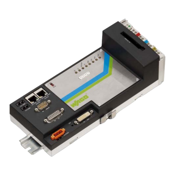
WAGO-I/O-SYSTEM 750 Device Description 758-874/000-110 WAGO-I/O-IPC-C6 Pos: 32.10 /Serie 758 (Funk, IPC und PFC)/Gerätebeschreibung/Anschlüsse/Anschlüsse 758-87x ohne Feldbus - Bild @ 10\mod_1313390563107_21.doc @ 76827 @ 2 @ 1 Übersicht der physikalischen Schnittstellen Overview of Physical Interfaces Stop Figure 1: Overview of interfaces Pos: 32.11 /Serie 758 (Funk, IPC und PFC)/Gerätebeschreibung/Anschlüsse/Anschlüsse 758-87x allgemein -Tabelle 1 @ 10\mod_1312355635368_21.doc @ 75620 @ @ 1... -
Page 20: Display Elements
Device Description WAGO-I/O-SYSTEM 750 758-874/000-110 WAGO-I/O-IPC-C6 Pos: 32.14 /Alle Serien (Allgemeine Module)/Überschriften für alle Serien/Gerätebeschreibung/Anzeigeelemente - Überschrift 2 @ 4\mod_1240984390875_21.doc @ 31964 @ 2 @ 1 Display Elements 40 41 Pos: 32.15 /Serie 758 (Funk, IPC und PFC)/Gerätebeschreibung/Anzeigeelemente/Anzeigeelemente 758-87x ohne Feldbus - Bild @ 10\mod_1313390715396_21.doc @ 76831 @ @ 1... -
Page 21: Operating Elements
Mounting rail For fastening the I/O-IPC to a grounded mounting rail. fastener Marker strips For 4-character identification of the I/O-IPC via WAGO Miniature WSB Quick marking system. Run: Automatic start of the boot project (CoDeSys) when starting Run/Stop the I/O-IPC or when starting the PLC program. -
Page 22: Battery
Device Description WAGO-I/O-SYSTEM 750 758-874/000-110 WAGO-I/O-IPC-C6 Pos: 32.24 /Serie 758 (Funk, IPC und PFC)/Gerätebeschreibung/Batterie/Batterie 758-87x - Überschrift 2 @ 10\mod_1314790319035_21.doc @ 77911 @ 2 @ 1 Battery Pos: 32.25 /Serie 758 (Funk, IPC und PFC)/Gerätebeschreibung/Batterie/Batterie 758-87x CR2025 @ 10\mod_1314684160789_21.doc @ 77496 @ @ 1 The 3 V battery (52) of type CR2025 (LiMnO , ca.165 mAh) is located... -
Page 23: Labeling
WAGO-I/O-SYSTEM 750 Device Description 758-874/000-110 WAGO-I/O-IPC-C6 Pos: 32.29 /Alle Serien (Allgemeine Module)/Überschriften für alle Serien/Gerätebeschreibung/Bedruckung - Überschrift 2 @ 4\mod_1241082409515_21.doc @ 32035 @ 2 @ 1 Labeling Pos: 32.30 /Serie 758 (Funk, IPC und PFC)/Gerätebeschreibung/Bedruckung/Bedruckung 758-87x allgemein ohne Exi @ 10\mod_1314792404986_21.doc @ 77933 @ @ 1 There is a label on the side of the I/O-IPC with the following information: •... -
Page 24: Technical Data
Device Description WAGO-I/O-SYSTEM 750 758-874/000-110 WAGO-I/O-IPC-C6 Pos: 32.34 /Alle Serien (Allgemeine Module)/Überschriften für alle Serien/Gerätebeschreibung/Technische Daten - Überschrift 2 @ 3\mod_1232967587687_21.doc @ 26924 @ 2 @ 1 Technical Data Pos: 32.35 /Serie 758 (Funk, IPC und PFC)/Gerätebeschreibung/Technische Daten/Gerätedaten 758-87x @ 10\mod_1312372717751_21.doc @ 75757 @ 3 @ 1 4.6.1... -
Page 25: System Data
WAGO-I/O-SYSTEM 750 Device Description 758-874/000-110 WAGO-I/O-IPC-C6 Pos: 32.37 /Serie 758 (Funk, IPC und PFC)/Gerätebeschreibung/Technische Daten/Systemdaten 758-87x allgemein 1 @ 10\mod_1312372761268_21.doc @ 75760 @ 3 @ 1 4.6.2 System Data Table 4: Technical data – System data Number of I/O modules that... -
Page 26: Communication
Runtime System Table 8: Technical data – Runtime System Programming CoDeSys 2.3 (WAGO-I/O-PRO CAA) IEC 61131-3 IL, LD, FBD, ST, FC Pos: 32.46 /Serie 758 (Funk, IPC und PFC)/Gerätebeschreibung/Technische Daten/Umgebungsbedingungen 758-87x allgemein @ 10\mod_1312373632441_21.doc @ 75794 @ 3 @ 1 4.6.7... -
Page 27: Wire Connection
WAGO-I/O-SYSTEM 750 Device Description 758-874/000-110 WAGO-I/O-IPC-C6 Pos: 32.49 /Serie 758 (Funk, IPC und PFC)/Gerätebeschreibung/Technische Daten/Anschlusstechnik 758-87x @ 10\mod_1312373715255_21.doc @ 75797 @ 3 @ 1 4.6.8 Wire Connection Table 10: Technical Data – Wire Connection ® Wire connection CAGE CLAMP Cross section 0.08 mm... -
Page 28: Approvals
Pos: 32.53 /Alle Serien (Allgemeine Module)/Überschriften für alle Serien/Gerätebeschreibung/Zulassungen - Überschrift 2 @ 3\mod_1224055364109_21.doc @ 24030 @ 2 @ 1 Approvals Pos: 32.54 /Serie 750 (WAGO-I/O-SYSTEM)/Gerätebeschreibung/Zulassungen/Information: Weitere Informationen zu Zulassungen 750-xxxx @ 3\mod_1227190967156_21.doc @ 25221 @ @ 1 More Information about Approvals Detailed references to the approvals are listed in the document "Overview... -
Page 29: Description Of I/O-Ipc Interfaces
WAGO-I/O-SYSTEM 750 Description of I/O-IPC Interfaces 758-874/000-110 WAGO-I/O-IPC-C6 Pos: 34.1 /Serie 758 (Funk, IPC und PFC)/Beschreibung der Schnittstellen/Beschreibung der Schnittstellen 758-87x ETHERNET 1 @ 10\mod_1312374986842_21.doc @ 75809 @ 12 @ 1 Description of I/O-IPC Interfaces ETHERNET Interfaces (X8, X9) Both ETHERNET interfaces of type RJ-45 are based on the 10/100 BASE-T transmission standard. -
Page 30: Interface For Electronic Power Supply (X4)
Description of I/O-IPC Interfaces WAGO-I/O-SYSTEM 750 758-874/000-110 WAGO-I/O-IPC-C6 Pos: 34.4 /Serie 758 (Funk, IPC und PFC)/Beschreibung der Schnittstellen/Beschreibung der Schnittstellen 758-87x Elektronikversorgung @ 10\mod_1314943943948_21.doc @ 78033 @ 2 @ 1 Interface for Electronic Power Supply (X4) Feed the electronic power supply for the I/O-IPC and for the I/O modules connected to the internal data bus in through this interface. -
Page 31: Integrated Inputs And Outputs (X5)
WAGO-I/O-SYSTEM 750 Description of I/O-IPC Interfaces 758-874/000-110 WAGO-I/O-IPC-C6 Pos: 34.6 /Serie 758 (Funk, IPC und PFC)/Beschreibung der Schnittstellen/Beschreibung der Schnittstellen 758-87x (onBoard I/Os, USB, ...) Einleitung @ 10\mod_1312375295737_21.doc @ 75820 @ 2 @ 1 Integrated Inputs and Outputs (X5) The 12-pole D-sub connector provides two integrated digital inputs and two outputs. -
Page 32: Figure 7: Connection Of Integrated Inputs
Description of I/O-IPC Interfaces WAGO-I/O-SYSTEM 750 758-874/000-110 WAGO-I/O-IPC-C6 Pos: 34.9 /Serie 758 (Funk, IPC und PFC)/Beschreibung der Schnittstellen/Beschreibung der Schnittstellen 758-87x (onBoard I/Os, USB, ...) Ende @ 10\mod_1314943172178_21.doc @ 78022 @ 222 @ 1 Digital Inputs The two digital inputs are independent of the internal data bus. This means that digital signals are processed even if the internal data bus breaks down. -
Page 33: Figure 8: Connection Of Integrated Outputs
WAGO-I/O-SYSTEM 750 Description of I/O-IPC Interfaces 758-874/000-110 WAGO-I/O-IPC-C6 Digital Outputs Highest current carrying capacity of the output channels is 0.1A! Always observe the maximum current carrying capacity of 0.1A for the digital output channels. An increase in the current leads to overheating of the output driver and damage to the I/O-IPC. -
Page 34: Usb Interfaces (X10, X11)
Description of I/O-IPC Interfaces WAGO-I/O-SYSTEM 750 758-874/000-110 WAGO-I/O-IPC-C6 USB Interfaces (X10, X11) The USB interfaces are used to connect USB devices such as USB memory. If the connected USB device is not used, you can remove it at any time. If a USB memory is connected, it is important to remember to close any open files before removing the USB memory. -
Page 35: Serial Interface (X6)
WAGO-I/O-SYSTEM 750 Description of I/O-IPC Interfaces 758-874/000-110 WAGO-I/O-IPC-C6 RS-232 Serial Interface (X6) The following table provides information on the RS-232 interface pin assignments: Table 17: RS-232 Interface: Pin Assignments Connector Description DCD1 RXD1 TXD1 DTR1 1 2 3 4 5... -
Page 36: Dvi-I Interface (X7)
Description of I/O-IPC Interfaces WAGO-I/O-SYSTEM 750 758-874/000-110 WAGO-I/O-IPC-C6 Boot process During the boot process, attached devices are not permitted to send data to the RS-232 interface because the firmware will not start otherwise. However, if this cannot be excluded, comment the "serial" parameter out in the menu.lst file (/boot/grub/menu.lst):... -
Page 37: Figure 11: Dvi-I Interfave
WAGO-I/O-SYSTEM 750 Description of I/O-IPC Interfaces 758-874/000-110 WAGO-I/O-IPC-C6 The following table provides information on the DVI-I interface pin assignments: Table 18: DVI-I Interface: Pin Assignments Connector Description TXD2- TXD2+ Not assigned Not assigned DDCCLK DDCDATA CRT_VSY CRT_R CRT_HSY TXD1- TXD1+ Not assigned …... -
Page 38: Installing And Removing The I/O-Ipc
Installing and Removing the I/O-IPC WAGO-I/O-SYSTEM 750 758-874/000-110 WAGO-I/O-IPC-C6 Pos: 36.1 /Serie 758 (Funk, IPC und PFC)/Montieren/Montage 758-87x Einleitung 1 @ 10\mod_1312436538898_21.doc @ 75830 @ 12 @ 1 Installing and Removing the I/O-IPC The I/O-IPC has an elevated generation of heat. Excess heat is drawn off by passive heat dissipation (aluminum underside of the I/O-IPC and mounting rail). -
Page 39: Accessories Required For Installation
WAGO-I/O-SYSTEM 750 Installing and Removing the I/O-IPC 758-874/000-110 WAGO-I/O-IPC-C6 Accessories Required for Installation To install the I/O-IPC, you will need • perforated or non-perforated mounting rails according to EN 60715 and • a 750-600 End Module. Acceptable Mounting Directions for the I/O-IPC The I/O-IPC can be mounted either horizontally or vertically on a mounting rail. -
Page 40: Securing The I/O-Ipc To A Mounting Rail
Installing and Removing the I/O-IPC WAGO-I/O-SYSTEM 750 758-874/000-110 WAGO-I/O-IPC-C6 Pos: 36.7 /Serie 758 (Funk, IPC und PFC)/Montieren/Montage 758-87x - Überschrift 2 @ 10\mod_1312436839609_21.doc @ 75837 @ 2 @ 1 Securing the I/O-IPC to a Mounting Rail Pos: 36.8 /Serie 758 (Funk, IPC und PFC)/Montieren/Montage 758-87x Einleitung @ 10\mod_1314955106193_21.doc @ 78070 @ @ 1 For installing the I/O-IPC on a mounting rail, there are four clamp levers on the underside that secure the I/O-IPC to the mounting rail. -
Page 41: Connecting The I/O Module To The I/O-Ipc
I/O modules. The same limitations apply in this case as for the use of 64 I/O modules. Using the WAGO internal data bus extension Information on the use of the WAGO internal data bus extension can be found in the 750-627 and 750-628 documentation, which can be obtained from the WAGO internet site. -
Page 42: Figure 14: Connecting An I/O Module To The I/O-Ipc Connecting Clamp
Installing and Removing the I/O-IPC WAGO-I/O-SYSTEM 750 758-874/000-110 WAGO-I/O-IPC-C6 To connect the I/O modules, proceed as described below: Disconnect from the power supply those parts of the system on which you wish to mount the I/O-IPC. Insert the slot (71) of each I/O module onto the key (70) of the previous module. -
Page 43: Dismounting The I/O-Ipc
WAGO-I/O-SYSTEM 750 Installing and Removing the I/O-IPC 758-874/000-110 WAGO-I/O-IPC-C6 Pos: 36.17 /Serie 758 (Funk, IPC und PFC)/Montieren/Demontage 758-87x allgemein 1 @ 10\mod_1312439787258_21.doc @ 75849 @ 2 @ 1 Dismounting the I/O-IPC To replace an I/O-IPC (e.g., in the event of version change), proceed as described in the following section. -
Page 44: Removing The I/O-Ipc From The Mounting Rail
Installing and Removing the I/O-IPC WAGO-I/O-SYSTEM 750 758-874/000-110 WAGO-I/O-IPC-C6 Pos: 36.22 /Serie 758 (Funk, IPC und PFC)/Montieren/Demontage 758-87x allgemein 2 @ 10\mod_1312441023649_21.doc @ 75856 @ 3 @ 1 6.6.2 Removing the I/O-IPC from the Mounting Rail Remove the I/O-IPC from the mounting rail as described below: First, disconnect from the power supply those parts of the system on which you have mounted the I/O-IPC. -
Page 45: Connecting The Supply Voltage
WAGO-I/O-SYSTEM 750 Connecting the Supply Voltage 758-874/000-110 WAGO-I/O-IPC-C6 Pos: 38.1 /Serie 758 (Funk, IPC und PFC)/Anschluss Daten- und Versorgungskabel/Anschluss Daten- und Versorgungskabel 758-87x Einleitung @ 10\mod_1312441245283_21.doc @ 75864 @ 1 @ 1 Connecting the Supply Voltage The supply voltage is connected as follows, depending on the application area of... -
Page 46: Required Accessories
758-874/000-110 WAGO-I/O-IPC-C6 Required Accessories To connect the supply power to the I/O-IPC potentially requires the 750-626 Filter Module. It can be ordered at www.wago.com. The customer provides the accessories (e.g. individual cables) and tools required to connect the supply power. -
Page 47: Power Supply Via 750-602 Supply Module
WAGO-I/O-SYSTEM 750 Connecting the Supply Voltage 758-874/000-110 WAGO-I/O-IPC-C6 Power supply via 750-602 Supply Module Scope of Delivery The 750-602 Supply Module is no longer included in the scope of delivery as of HW Version 11. Length of the power supply cable With this type of power supply, the length of the power supply cable shall not exceed 3 meters from the voltage source to the I/O-IPC X4 connection. -
Page 48: Table 20: Connections, Contacts And Supply Module Leds
Connecting the Supply Voltage WAGO-I/O-SYSTEM 750 758-874/000-110 WAGO-I/O-IPC-C6 Table 20: Connections, contacts and supply module LEDs Position LED/Operating Element Color/ Meaning Status Earth Connection of protective earth 0 V DC Ground (GND) of the supply voltage Field supply, 24 V DC 24V supply voltage for the sensors/actuators. -
Page 49: Figure 18: Power Supply Via 750-602 Up To Hw 10 (Without Fieldbus)
WAGO-I/O-SYSTEM 750 Connecting the Supply Voltage 758-874/000-110 WAGO-I/O-IPC-C6 Pos: 38.5 /Serie 758 (Funk, IPC und PFC)/Anschluss Daten- und Versorgungskabel/Anschluss Daten- und Versorgungskabel 758-87x allgemein 1.1 @ 10\mod_1313409070108_21.doc @ 76965 @ @ 1 To connect the supply cable for the I/O-IPC electronic supply and for feeding in... -
Page 50: Figure 19: Power Supply Via 750-602 As Of Hw 11 (Without Fieldbus)
Connecting the Supply Voltage WAGO-I/O-SYSTEM 750 758-874/000-110 WAGO-I/O-IPC-C6 V_IN 1,6 A 10 A 24 V 24 V Electronic power supply Field power supply Figure 19: Power Supply via 750-602 as of HW 11 (without fieldbus) Pos: 38.10 /Dokumentation allgemein/Gliederungselemente/---Seitenwechsel--- @ 3\mod_1221108045078_0.doc @ 21810 @ @ 1 Manual Version 2.3.0... -
Page 51: Power Supply Via 750-626 Filter Module
For this power supply variant, you will need the 750-626 Filter Module starting with hardware version 4. This is the only filter module configured for the higher current carrying capacity. You can obtain the filter module from www.wago.com. Observe the isolation voltage! When using the 750-626 Filter Module, the isolation voltage of the field and electronic power supply is reduced to 50 V against ground. -
Page 52: Figure 20: Power Supply Via 750-626 (Without_Fieldbus)
Connecting the Supply Voltage WAGO-I/O-SYSTEM 750 758-874/000-110 WAGO-I/O-IPC-C6 Pos: 38.15 /Serie 758 (Funk, IPC und PFC)/Anschluss Daten- und Versorgungskabel/Anschluss Daten- und Versorgungskabel 758-87x 2.0 @ 10\mod_1313409103611_21.doc @ 76984 @ @ 1 To connect the I/O-IPC electronic supply and the field supply for the connected... -
Page 53: Connecting Sensor And Actuator Lines To I/O Modules
Modules You can find additional information and instructions for wiring individual WAGO I/O modules in the WAGO-I/O SYSTEM 750 system description, and the respective manuals and data sheets at www.wago.com. Pos: 39 /Dokumentation allgemein/Gliederungselemente/---Seitenwechsel--- @ 3\mod_1221108045078_0.doc @ 21810 @ @ 1 Manual Version 2.3.0... -
Page 54: Commissioning
Commissioning WAGO-I/O-SYSTEM 750 758-874/000-110 WAGO-I/O-IPC-C6 Pos: 40 /Alle Serien (Allgemeine Module)/Überschriften für alle Serien/Inbetriebnehmen - Konfigurieren - Parametrieren/In Betrieb nehmen - Überschrift 1 @ 4\mod_1240901452750_21.doc @ 31570 @ 1 @ 1 Commissioning Pos: 41.1 /Serie 758 (Funk, IPC und PFC)/In Betrieb nehmen/In Betrieb nehmen 758-87x allgemein 1 @ 10\mod_1312442544398_21.doc @ 75883 @ 222 @ 1... -
Page 55: Determining The Ip Address Of A Host Pc
WAGO-I/O-SYSTEM 750 Commissioning 758-874/000-110 WAGO-I/O-IPC-C6 Determining the IP Address of a Host PC So that the host PC (e.g. notebook) can communicate with an I/O-IPC via the ETHERNET, both must be located in the same subnet. To determine the IP address of a host PC (with MS Windows operating system) using the MS-DOS prompt, proceed as follows: Click on "Start"... -
Page 56: Setting Up An Ip Address
The assignment of the IP address using BootP is explained here using an example with the WAGO BootP Server. Prerequisite: The WAGO BootP Server can be installed on your PC. It can be obtained at www.wago.com. Manual Version 2.3.0... -
Page 57: Figure 21: Configuration Line In The Configuration File
You can find this on the label on the side of the I/O-IPC (see Section "Lateral Marking"). Turn on your PC. In the "Start" menu, start the WAGO BootP Server by navigating to Programs >WAGO Software > WAGO BOOTP Server. Open the configuration file by clicking on the [Edit BootPtab] button in the BootP Server. -
Page 58: Table 25: Explanations Of The Configuration Line
Commissioning WAGO-I/O-SYSTEM 750 758-874/000-110 WAGO-I/O-IPC-C6 Table 25: Explanations of the configuration line Parameter Description Node_1 Name of the I/O-IPC with the I/O modules. This can be freely chosen. ht=1 Network hardware type. For ETHERNET, this is 1. ha=0030DE000200 MAC address of an ETHERNET interface. -
Page 59: Figure 22: Dialog Window Of The Wago Bootp Server With Messages
You can ignore these error messages. 192.168.1.100 Figure 22: Dialog window of the WAGO BootP Server with messages Restart the I/O-IPC by switching the supply voltage of the I/O-IPC off and then on again, or by pressing the reset button. -
Page 60: Changing An Ip Address Using The Linux Console (Ipc Configuration Tool)
Using the key combination [Alt] + [F3], open the third console of the I/O- IPC on which the IPC configuration tool is located. Figure 23: Start screen of the WAGO IPC configuration tool Use the keyboard (arrow keys or number block) to select the TCP/IP entry and press the [Enter] key. -
Page 61: Figure 25: Tcp/Ip Configuration Eth0 (X8)
WAGO-I/O-SYSTEM 750 Commissioning 758-874/000-110 WAGO-I/O-IPC-C6 Pos: 41.5 /Serie 758 (Funk, IPC und PFC)/In Betrieb nehmen/In Betrieb nehmen 758-87x 4 @ 11\mod_1315222587717_21.doc @ 78212 @ @ 1 To change the X8 Ethernet interface, select TCP/IP Configuration eth0 or TCP/IP Configuration eth1 for the X9 Ethernet interface. Then press the [Enter] key. -
Page 62: Figure 27: Enter New Address
Commissioning WAGO-I/O-SYSTEM 750 758-874/000-110 WAGO-I/O-IPC-C6 Enter the new IP address for the selected Ethernet interface and confirm it with [OK]. If you want to return to the main menu without making changes, select [Abort]. Figure 27: Enter new address Note You cannot assign IP addresses for both Ethernet interfaces in the same subnet. -
Page 63: Testing The Network Connection
WAGO-I/O-SYSTEM 750 Commissioning 758-874/000-110 WAGO-I/O-IPC-C6 Pos: 41.7 /Serie 758 (Funk, IPC und PFC)/In Betrieb nehmen/In Betrieb nehmen 758-87x allgemein 5 @ 11\mod_1315222596607_21.doc @ 78218 @ 2 @ 1 Testing the Network Connection To check whether you can reach the I/O-IPC at the IP address you have assigned in the network, carry out the ping network service. -
Page 64: Switch Off/Re-Start
Commissioning WAGO-I/O-SYSTEM 750 758-874/000-110 WAGO-I/O-IPC-C6 Pos: 41.9 /Serie 758 (Funk, IPC und PFC)/In Betrieb nehmen/In Betrieb nehmen 758-87x 6 -Überschrift @ 11\mod_1315222738358_21.doc @ 78221 @ 2 @ 1 Switch Off/Re-start Pos: 41.10 /Serie 758 (Funk, IPC und PFC)/Wichtige Erläuterungen/Sicherheitshinweise/Sicherheitshinweise 758-87x Heiße Oberseite PIKTOGRAMM @ 10\mod_1315199932690_21.doc @ 78103 @ @ 1... -
Page 65: Configuration
WAGO-I/O-SYSTEM 750 Configuration 758-874/000-110 WAGO-I/O-IPC-C6 Pos: 43 /Alle Serien (Allgemeine Module)/Überschriften für alle Serien/Inbetriebnehmen - Konfigurieren - Parametrieren/Konfigurieren - Überschrift 1 @ 5\mod_1247578046546_21.doc @ 37410 @ 1 @ 1 Configuration Pos: 44.1 /Serie 758 (Funk, IPC und PFC)/Konfigurieren/Konfigurieren 785-87x - allgemein 1 @ 10\mod_1312455450627_21.doc @ 75901 @ 2 @ 1 The following methods are available for configuring the I/O-IPC: •... -
Page 66: Web-Based Management (Wbm)
Configuration WAGO-I/O-SYSTEM 750 758-874/000-110 WAGO-I/O-IPC-C6 Web-Based Management (WBM) The implemented HTML pages (abbreviated as "pages" in the following) for Web-Based Management are used to configure the I/O-IPC. To access Web- Based Management, proceed as follows: Pos: 44.2 /Serie 758 (Funk, IPC und PFC)/Konfigurieren/Konfigurieren 785-87x 2 @ 11\mod_1315226371364_21.doc @ 78257 @ @ 1 Connect the I/O-IPC via the X9 ETHERNET interface to the ETHERNET network. -
Page 67: User Administration Of Wbm
WAGO-I/O-SYSTEM 750 Configuration 758-874/000-110 WAGO-I/O-IPC-C6 9.1.1 User Administration of WBM To allow settings to be made by a select number of person only, limit access to WBM functions through User Administration. Passwords Please change the passwords for your own use since the standard passwords are documented in these instructions. -
Page 68: Information" Page
Configuration WAGO-I/O-SYSTEM 750 758-874/000-110 WAGO-I/O-IPC-C6 9.1.2 "Information" Page After entering the IP address, the start page "Information" for web-based management appears. This page provides information on the I/O-IPC and the ETHERNET network. Figure 31: "Information" page (Example) The following table explains the parameters listed on the page: Table 28: Description of the Parameters of the "Information"... -
Page 69: Codesys" Page
WAGO-I/O-SYSTEM 750 Configuration 758-874/000-110 WAGO-I/O-IPC-C6 9.1.3 "CoDeSys" Page You will all information about the PLC program created in CoDeSys on that page. Table 29: Description of the Parameters of the "CoDeSys" Page Project Details Date Display of project information that the programmer entered in the PLC program (in CoDeSys under Project >... -
Page 70: Tcp/Ip" Page
Configuration WAGO-I/O-SYSTEM 750 758-874/000-110 WAGO-I/O-IPC-C6 9.1.4 "TCP/IP" Page On the page for TCP/IP configuration, change the parameters for the ETHERNET configuration. To accept your entries, click on the [SUBMIT] button. Table 30: Description of the Parameters of the "TCP/IP" Page... -
Page 71: Ethernet" Page
WAGO-I/O-SYSTEM 750 Configuration 758-874/000-110 WAGO-I/O-IPC-C6 9.1.5 "ETHERNET" Page Configure the transmission speed and communication method of the I/O-IPC ETHERNET interface on this page. To accept your entries, click on the [SUBMIT] button. Table 31: Description of the Parameters of the "ETHERNET" Page Transmission Mode Eth0 und Eth1 When the function is enabled, two ETHERNET interfaces (e.g. -
Page 72: Clock" Page
Configuration WAGO-I/O-SYSTEM 750 758-874/000-110 WAGO-I/O-IPC-C6 9.1.7 "Clock" Page On this page, configure the real-time clock. To accept your entries, click on the [CHANGE] button. Enter the time zone Your time zone entries are not active until after a restart/reset of the I/O-IPC. -
Page 73: Users" Page
WAGO-I/O-SYSTEM 750 Configuration 758-874/000-110 WAGO-I/O-IPC-C6 9.1.8 "Users" Page On this page, change the passwords for WBM of the users admin and user. To do this, you must be logged on as the user admin. An overview of passwords can be found in Section "User Administration of WBM". -
Page 74: Hmi Settings" Page
Configuration WAGO-I/O-SYSTEM 750 758-874/000-110 WAGO-I/O-IPC-C6 9.1.9 "HMI Settings" Page On the "HMI Settings" page, change the graphic resolution for the DVI-I interface, configure the touch screen or monitor, and choose between a English or German keyboard layout. To save all settings made on the page, click the [SUBMIT] button. The I/O-IPC must be restarted or reset to apply the settings. - Page 75 WAGO-I/O-SYSTEM 750 Configuration 758-874/000-110 WAGO-I/O-IPC-C6 Table 35: Description of the Screensaver and Cleanmode parameters on the "HMI Settings" page Cleanmode Indicates whether Cleanmode is currently active or inactive active: green check and text "on" inactive red cross and text "off"...
-
Page 76: Administration" Page
Configuration WAGO-I/O-SYSTEM 750 758-874/000-110 WAGO-I/O-IPC-C6 Table 35: Description of the Screensaver and Cleanmode parameters on the "HMI Settings" page Touchscreen Configuration This is where you select a touch screen (mouse dev) connected via USB. The I/O-IPC does not support serially connected touch screens. -
Page 77: Table 36: Description Of The Parameters Of The "Administration" Page
Here, select the service that is to be executed on the serial interface. To accept your entries, click on the [SUBMIT] button. MODBUS RTU Activating "Control Mode“ in WAGO-IO-CHECK! Using WAGO-IO-CHECK, you can overwrite parameters and process data in "Control Mode"... -
Page 78: Package Server" Page
Configuration WAGO-I/O-SYSTEM 750 758-874/000-110 WAGO-I/O-IPC-C6 Pos: 44.6 /Serie 758 (Funk, IPC und PFC)/Konfigurieren/Konfigurieren 785-87x - allgemein 5 @ 12\mod_1331131418014_21.doc @ 90415 @ 3333333322 @ 1 9.1.11 "Package Server" Page From the "Package Server" page, copy the firmware as a "backup package" from the current partition of the I/O-IPC to devices attached to the I/O-IPC. - Page 79 WAGO-I/O-SYSTEM 750 Configuration 758-874/000-110 WAGO-I/O-IPC-C6 Table 37: Description of the Parameters of the "Package Server" Page When creating packages using this function, the packages are automatically copied from the media (CF card/USB storage) to the device when starting the device.
-
Page 80: Mass Storage" Page
Configuration WAGO-I/O-SYSTEM 750 758-874/000-110 WAGO-I/O-IPC-C6 9.1.12 "Mass Storage" Page The "Mass Storage" page provides information about the mass storage media available for the IPC and can perform different actions in this regard. A separate table is displayed for each media available. -
Page 81: Port" Page
WAGO-I/O-SYSTEM 750 Configuration 758-874/000-110 WAGO-I/O-IPC-C6 9.1.14 "Port" Page On this page for protocol configuration, select the protocol that you would like to use for communication. You have a choice between the following protocols: • Telnet When using the Linux console through ETHERNET •... -
Page 82: Page „Snmp
Configuration WAGO-I/O-SYSTEM 750 758-874/000-110 WAGO-I/O-IPC-C6 9.1.16 Page „SNMP“ On this page, change the parameters for the "Simple Network Management Protocol" on the SNMP configuration page. To accept your entries, click on the [SUBMIT] button or delete them by clicking on [DELETE]. -
Page 83: I/O Configuration
WAGO-I/O-SYSTEM 750 Configuration 758-874/000-110 WAGO-I/O-IPC-C6 Table 40: Description of the parameters for the "SNMP" page SNMP v3 Configuration A list of all configured v3 users is indicated here. The number of users is in principle not limited by the I/O-IPC. You have the opportunity to delete individually configured Users via [DELETE]. -
Page 84: Webvisu" Page
Configuration WAGO-I/O-SYSTEM 750 758-874/000-110 WAGO-I/O-IPC-C6 9.1.18 "WebVisu" Page On the "WebVisu" page, you select whether the WBM or CoDeSys web visualization should appear when entering the IP address of the I/O-IPC. To save all settings made on the page, click the [SUBMIT] button. The I/O-IPC must be restarted or reset to apply the settings. -
Page 85: Configuration With Touch Screen/Monitor And Usb Keyboard
IPC configuration tool is located. You cannot quit this Linux console. Therefore, "QUIT" on the navigation bar has no function. Figure 33: Start screen of the WAGO IPC configuration tool Pos: 45 /Dokumentation allgemein/Gliederungselemente/---Seitenwechsel--- @ 3\mod_1221108045078_0.doc @ 21810 @ @ 1 Manual Version 2.3.0... -
Page 86: Modbus/Tcp
MODBUS/TCP WAGO-I/O-SYSTEM 750 758-874/000-110 WAGO-I/O-IPC-C6 Pos: 46.1 /Serie 758 (Funk, IPC und PFC)/Feldbuskommunikation/Feldbuskommunikation 758-87x MODBUS allgemein @ 10\mod_1312456038415_21.doc @ 75904 @ 12233 @ 1 MODBUS/TCP The modular concept of the 750 Series makes it possible to connect up to 250 (via internal data bus extension) I/O modules to the I/O-IPC. -
Page 87: Process Data Of The Modbus Server
Data Architecture for MODBUS/TCP." Activating "Control Mode“ in WAGO-IO-CHECK! Using WAGO-IO-CHECK, you can overwrite parameters and process data in "Control Mode" regardless of whether the fieldbus or PLC functionalities are enabled or disabled. By doing so, machine components may be placed in a dangerous state and personnel and machines may be at risk. -
Page 88: Register Services
MODBUS/TCP WAGO-I/O-SYSTEM 750 758-874/000-110 WAGO-I/O-IPC-C6 10.2.1 Register Services With the register services, determine or change the statuses of analog input and output terminals for the following address ranges: Table 45: Reading Analog Input Terminals Using FC3, FC4, FC23 MODBUS Address... -
Page 89: Bit Services
WAGO-I/O-SYSTEM 750 MODBUS/TCP 758-874/000-110 WAGO-I/O-IPC-C6 10.2.2 Bit Services With the digital bit services, determine or change the statuses of digital input and output terminals for the following address ranges: Table 47: Reading of Digital Input Terminals Using FC1, FC2 MODBUS Address Addresses in CoDeSys... -
Page 90: Configuration Tab
MODBUS/TCP WAGO-I/O-SYSTEM 750 758-874/000-110 WAGO-I/O-IPC-C6 Pos: 46.3 /Serie 758 (Funk, IPC und PFC)/Feldbuskommunikation/Feldbuskommunikation 758-87x MODBUS Konfigurationsregister @ 11\mod_1315373711867_21.doc @ 78360 @ 2 @ 1 10.3 Configuration Tab By using the MODBUS configuration register, you can configure the I/O-IPC and read out information through it. -
Page 91: Table 49: Arrangement Of The I/O Modules For The Addressing Example
WAGO-I/O-SYSTEM 750 MODBUS/TCP 758-874/000-110 WAGO-I/O-IPC-C6 Pos: 46.5 /Serie 758 (Funk, IPC und PFC)/Feldbuskommunikation/Feldbuskommunikation 758-87x MODBUS Adressierungsbeispiel allgemein @ 11\mod_1315373747056_21.doc @ 78366 @ 2 @ 1 10.4 Addressing Example The following addressing example clarifies the access to the process image: Table 49: Arrangement of the I/O modules for the addressing example... -
Page 92: Codesys 2.3 Runtime Environment
CoDeSys 2.3 Runtime Environment WAGO-I/O-SYSTEM 750 758-874/000-110 WAGO-I/O-IPC-C6 Table 50: Addressing example I/O Module Input Data Output Data Description Type C* FC3, FC1, End module The passive 750-600 End Module does not 750-600 transmit any data. Analog input/output modules Digital input/output modules *C: Number of the input/output Pos: 46.6 /Serie 758 (Funk, IPC und PFC)/Feldbuskommunikation/CoDeSys 758-87x - Überschrift 1 @ 10\mod_1313151338247_21.doc @ 76730 @ 1 @ 1... -
Page 93: Access To The Process Images Of The Input And Output Data Via Codesys 2.3
WAGO-I/O-SYSTEM 750 CoDeSys 2.3 Runtime Environment 758-874/000-110 WAGO-I/O-IPC-C6 11.2 Access to the Process Images of the Input and Output Data via CoDeSys 2.3 The following table describes the possibilities with which you can access the address ranges of the process image for the inputs and outputs connected to the... -
Page 94: Table 52: Memory Areas For The Input And Output Data Of Codesys
Write SRAM: 1023 kBytes The use of up to 250 I/O modules is possible with the WAGO internal data bus extension modules. Only for I/O-IPC with fieldbus connections The total memory size for flag and retain variables is 1023 kB). Use bit-oriented addressing and observe that the base address is word-oriented. -
Page 95: Figure 34: Adaptation Of The Remanent Memory Area
WAGO-I/O-SYSTEM 750 CoDeSys 2.3 Runtime Environment 758-874/000-110 WAGO-I/O-IPC-C6 • Remanent memory area of 8 kB Memory: 16#2000 (8 kB) Retain: 16#FDF00 (1015 kB) Sum: 16#FFF00 (1023 kB)) • Remanent memory area of 16 kB Memory: 16#4000 (16 kB) Retain: 16#FBF00 (1007 kB) -
Page 96: Addressing Example
CoDeSys 2.3 Runtime Environment WAGO-I/O-SYSTEM 750 758-874/000-110 WAGO-I/O-IPC-C6 11.3 Addressing Example The following addressing example clarifies the access to the process image: Table 53: Arrangement of the I/O modules for the addressing example I/O-IPC 750- 750- 750- 750- 750- 750-... -
Page 97: Installing The Programming System Codesys 2.3
Installing the Programming System CoDeSys 2.3 (WAGO-I/O-PRO CAA) The WAGO target files are installed during the installation of CoDeSys. These contain all device-specific information for the WAGO 750/758 product series. Proceed as described below to install the programming software CoDeSys 2.3 on the I/O-IPC. -
Page 98: Designing A Project And Selecting The Target System
CoDeSys 2.3 Runtime Environment WAGO-I/O-SYSTEM 750 758-874/000-110 WAGO-I/O-IPC-C6 11.5.2 Designing a Project and Selecting the Target System Click on File in the menu bar and select New. The "Set Target System" window opens. Here, all available target systems that can be programmed with CoDeSys 2.3 are listed. -
Page 99: Figure 37: Designing A New Function Block
WAGO-I/O-SYSTEM 750 CoDeSys 2.3 Runtime Environment 758-874/000-110 WAGO-I/O-IPC-C6 Create a program function block in the "New POU" window. In this example, a new function block, "PLC_PRG", is created in the "ST" programming language. Click on [OK] to create the project. The programming interface opens. -
Page 100: Creating The Plc Configuration
CoDeSys 2.3 Runtime Environment WAGO-I/O-SYSTEM 750 758-874/000-110 WAGO-I/O-IPC-C6 11.5.3 Creating the PLC Configuration Procedure for the creation of the PLC configuration Use an I/O-IPC with a fieldbus connection, then proceed with the creation of the PLC configuration as described in section "CANopen Master in CoDeSys 2.3" or "PROFIBUS Master in CoDeSys 2.3". -
Page 101: Figure 40: Plc Configuration: Appending Sub-Elements
WAGO-I/O-SYSTEM 750 CoDeSys 2.3 Runtime Environment 758-874/000-110 WAGO-I/O-IPC-C6 Double click on "PLC Configuration" in the left field. This opens the PLC configuration of the I/O-IPC. Right click on the entry "K-Bus[Fix]" and select "Append Subelement" in the context menu. The "I/O-Configuration" dialog opens. -
Page 102: Figure 42: I/O Configuration 2
CoDeSys 2.3 Runtime Environment WAGO-I/O-SYSTEM 750 758-874/000-110 WAGO-I/O-IPC-C6 You can change the position of an I/O module in the right window by marking it and then moving it up or down using the arrow button on the right edge of the window. -
Page 103: Figure 43: Plc Configuration: I/O Module With The Associated Addresses
WAGO-I/O-SYSTEM 750 CoDeSys 2.3 Runtime Environment 758-874/000-110 WAGO-I/O-IPC-C6 In the PLC configuration, the added I/O modules appear under "K-bus[FIX]" with the corresponding fixed addresses. Figure 43: PLC configuration: I/O module with the associated addresses You can declare a variable for each input and output (e.g., K-Bus_DI_01 and K-Bus_Do_01). -
Page 104: Editing A Program Function Block
CoDeSys 2.3 Runtime Environment WAGO-I/O-SYSTEM 750 758-874/000-110 WAGO-I/O-IPC-C6 11.5.4 Editing a Program Function Block To edit the program component PLC_PRG, change to the "POUs" tab and double click on the program function block PLC_PRG. Figure 45: Program function block The following example is intended to illustrate the editing of the program function block. -
Page 105: Figure 47: Example Of An Assignment
WAGO-I/O-SYSTEM 750 CoDeSys 2.3 Runtime Environment 758-874/000-110 WAGO-I/O-IPC-C6 Figure 47: Example of an assignment To compile, click on "Project" in the menu bar and select "Rebuild all". Manual Version 2.3.0... -
Page 106: Loading And Executing The Plc Program In Control (Ethernet)
CoDeSys 2.3 Runtime Environment WAGO-I/O-SYSTEM 750 758-874/000-110 WAGO-I/O-IPC-C6 11.5.5 Loading and Executing the PLC Program in Control (ETHERNET) Prerequisite: The simulation mode is disabled (Online > Simulation). You have connected the PC to the ETHERNET interface of the I/O-IPC via an ETHERNET cable (RJ-45). - Page 107 WAGO-I/O-SYSTEM 750 CoDeSys 2.3 Runtime Environment 758-874/000-110 WAGO-I/O-IPC-C6 Enter the IP address of your I/O-IPC in the "Address" field in the "Communication Parameters" window and then press the enter key on your PC keyboard. To close the window, click in the window on [OK].
-
Page 108: Loading And Executing The Plc Program In Control (Rs 232)
CoDeSys 2.3 Runtime Environment WAGO-I/O-SYSTEM 750 758-874/000-110 WAGO-I/O-IPC-C6 11.5.6 Loading and Executing the PLC Program in Control (RS 232) Prerequisite: The simulation mode is disabled (Online > Simulation). You have connected the PC to the serial interface of the I/O-IPC via a null modem cable. - Page 109 WAGO-I/O-SYSTEM 750 CoDeSys 2.3 Runtime Environment 758-874/000-110 WAGO-I/O-IPC-C6 Figure 15: Creating a new communication channel (RS 232) 2 Enter the following communication parameters of the RS-232 interface: • Baud rate: 115200 bit/sec • Parity: Even • Stop Bits: 1 •...
-
Page 110: Creating A Boot Project
CoDeSys 2.3 Runtime Environment WAGO-I/O-SYSTEM 750 758-874/000-110 WAGO-I/O-IPC-C6 11.5.7 Creating a Boot Project So that the PLC program automatically restarts after restarting the I/O-IPC, create a boot project. To do this, select Online > Create boot project in the menu bar. -
Page 111: Creating A Task Configuration
WAGO-I/O-SYSTEM 750 CoDeSys 2.3 Runtime Environment 758-874/000-110 WAGO-I/O-IPC-C6 11.6 Creating a Task Configuration With task configuration, you set the time response and priority of individual program function blocks. Watchdog In an application program without task configuration, there is no watchdog that monitors the cycle time of the application program (PLC_PRG). -
Page 112: Figure 48: Changing The Task Name
CoDeSys 2.3 Runtime Environment WAGO-I/O-SYSTEM 750 758-874/000-110 WAGO-I/O-IPC-C6 To assign a new name to the task (e.g. PLC_Prog), click on "NewTask". Then select the type of task. In this example, this is the "cyclic" type. Figure 48: Changing the task name Add the previously created program function block PLC_PRG (see section "Editing a Program Function Block") by right clicking on the "hour"... -
Page 113: Cyclical Task Priorities
WAGO-I/O-SYSTEM 750 CoDeSys 2.3 Runtime Environment 758-874/000-110 WAGO-I/O-IPC-C6 11.6.1 Cyclical Task Priorities You can assign a priority for each task in order to establish the task processing sequence. All tasks that access the process image of the I/O module are synchronized with it. -
Page 114: Freewheeling Tasks
CoDeSys 2.3 Runtime Environment WAGO-I/O-SYSTEM 750 758-874/000-110 WAGO-I/O-IPC-C6 Priority 11 – 15: Applications such as long-lasting arithmetic operations and non-real-time relevant accesses to the internal data bus, the ETHERNET, file system, fieldbus (only for I/O-IPC with fieldbus connections) and RS-232 interface should be carried out as tasks with the lowest priorities 11-15. -
Page 115: System Events
WAGO-I/O-SYSTEM 750 CoDeSys 2.3 Runtime Environment 758-874/000-110 WAGO-I/O-IPC-C6 11.7 System events Event tasks can be used in the CoDeSys task configuration in addition to cyclical tasks. Event tasks call up certain events in the device. You can activate events in the following dialog and input a called program:... -
Page 116: Table 55: Events
CoDeSys 2.3 Runtime Environment WAGO-I/O-SYSTEM 750 758-874/000-110 WAGO-I/O-IPC-C6 The following events can be activated: Table 55: Events Name Description start The event is called directly after the user program starts. stop The event is called directly after the user program stops. -
Page 117: I/O Module Synchronization
WAGO-I/O-SYSTEM 750 CoDeSys 2.3 Runtime Environment 758-874/000-110 WAGO-I/O-IPC-C6 11.8 I/O Module Synchronization The I/O module cycle and the CoDeSys task cycle are optimally automatically synchronized: This depends on the number of I/O modules connected and the fastest CoDeSys task cycle set in the I/O-IPC. The synchronization cases described below can therefore take place. -
Page 118: Case 2: The Codesys Task Interval Is Less Than Double The I/O Module Cycle
CoDeSys 2.3 Runtime Environment WAGO-I/O-SYSTEM 750 758-874/000-110 WAGO-I/O-IPC-C6 11.8.2 Case 2: The CoDeSys task interval is less than double the I/O module cycle The implementation of the I/O module is synchronized to the CoDeSys Task Interval set. At the end of the CoDeSys task, the I/O module cycle starts, which is processed synchronously with the fastest CoDeSys task. -
Page 119: Case 3: The Codesys Task Interval Is Greater Than Double The I/O Module Cycle
WAGO-I/O-SYSTEM 750 CoDeSys 2.3 Runtime Environment 758-874/000-110 WAGO-I/O-IPC-C6 11.8.3 Case 3: The CoDeSys task interval is greater than double the I/O module cycle The I/O data from the internal data bus are actualized once prior to the CoDeSys task and once after the CoDeSys task. -
Page 120: Case 4: Codesys Task Interval Greater Than 10 Ms
CoDeSys 2.3 Runtime Environment WAGO-I/O-SYSTEM 750 758-874/000-110 WAGO-I/O-IPC-C6 11.8.4 Case 4: CoDeSys Task interval greater than 10 ms The synchronization takes place as in Case 3; however, the output data busses would be reset to their default state after 150 ms without an I/O module cycle. -
Page 121: Codesys Visualization
WAGO-I/O-SYSTEM 750 CoDeSys 2.3 Runtime Environment 758-874/000-110 WAGO-I/O-IPC-C6 11.9 CoDeSys Visualization The CoDeSys Web visualization is based on Java technology. All Java programs require a Java runtime environment (JRE), which must be installed on the host PC along with an Internet browser. An applet (Java program) is created in the file system of a web server and made accessible through an HTML home page. -
Page 122: Figure 58: Generating The Plc_Visu Home Page
CoDeSys 2.3 Runtime Environment WAGO-I/O-SYSTEM 750 758-874/000-110 WAGO-I/O-IPC-C6 Generate a start page for the visualization. Use the right mouse button to click on the "Visualization" folder on the "Visualization" tab. Select Add object ... from the context menu. The "New visualization" dialog box opens. -
Page 123: Incorporating Fonts
• The graphics library of the CoDeSys target visualization accesses a directory in the file system of the WAGO-I/O-IPC in which you must store these fonts. You must create this directory. The easiest way to do this is via FTP access from the PC. -
Page 124: Limitations Of The Codesys Visualization
CoDeSys 2.3 Runtime Environment WAGO-I/O-SYSTEM 750 758-874/000-110 WAGO-I/O-IPC-C6 11.9.2 Limitations of the CoDeSys Visualization The visualization integrated in CoDeSys has the three variants "HMI", "TargetVisu" and "WebVisu", which are all supported by the I/O-IPC. Depending on the process variant, there are technological limitations. - Page 125 WAGO-I/O-SYSTEM 750 CoDeSys 2.3 Runtime Environment 758-874/000-110 WAGO-I/O-IPC-C6 Computer Performance/Processor Time The I/O-IPC is based on a real-time operating system. This means that high- priority processes (e.g., PLC program) will interrupt or block lower priority processes. The Web server responsible for Web visualization is among these lower priority processes.
-
Page 126: Eliminating Codesys Web Visualization Errors
CoDeSys 2.3 Runtime Environment WAGO-I/O-SYSTEM 750 758-874/000-110 WAGO-I/O-IPC-C6 11.9.3 Eliminating CoDeSys Web Visualization Errors If problems occur when using CoDeSys Web visualization, please try to find a solution in the following table first. If you cannot eliminate the problems, please contact WAGO support. -
Page 127: Frequently Asked Questions About Codesys Web Visualization
WAGO-I/O-SYSTEM 750 CoDeSys 2.3 Runtime Environment 758-874/000-110 WAGO-I/O-IPC-C6 11.9.4 Frequently Asked Questions About CoDeSys Web Visualization How can I optimize the applet for special screen resolutions? In order to optimize the Web visualization for a PDA or a touch panel with a fixed resolution, you should proceed as follows: In the "Target system settings", enter the pixel width and height in the tab... - Page 128 CoDeSys 2.3 Runtime Environment WAGO-I/O-SYSTEM 750 758-874/000-110 WAGO-I/O-IPC-C6 Why does the visualization element "TREND" in the Web visualization only work "Online"? The following settings must be selected for the visualization projects: Resources tab > Target system settings. Activate "Web visualization" and "Trend data recording within control."...
-
Page 129: Incorporation Of C-Functions As Codesys Library
WAGO-I/O-SYSTEM 750 Incorporation of C-Functions as CoDeSys Library 758-874/000-110 WAGO-I/O-IPC-C6 Pos: 46.9 /Serie 758 (Funk, IPC und PFC)/Feldbuskommunikation/C-Funktionen als CoDeSys-Bibliothek @ 10\mod_1312527555987_21.doc @ 75970 @ 123333323332 @ 1 Incorporation of C-Functions as CoDeSys Library For the use of any C- or also Linux functions in CoDeSys, the import interface described in the following is available. -
Page 130: Creating A Description File For The Codesys Runtime System
Incorporation of C-Functions as CoDeSys Library WAGO-I/O-SYSTEM 750 758-874/000-110 WAGO-I/O-IPC-C6 12.1.2 Creating a Description File for the CoDeSys Runtime System Create a description file with the fixed name "extlibs.ini" in order to make the C- functions known to the CoDeSys runtime system. -
Page 131: Copying A Library And Ini File And Restarting The Codesys Runtime System
WAGO-I/O-SYSTEM 750 Incorporation of C-Functions as CoDeSys Library 758-874/000-110 WAGO-I/O-IPC-C6 12.1.3 Copying a Library and INI File and Restarting the CoDeSys Runtime System To link the library and the INI file to the CoDeSys runtime system, proceed as follows: Copy both of the newly created files (libmytest.so and extlibs.ini) onto the I/O-IPC. -
Page 132: Creating An Iec Library
Incorporation of C-Functions as CoDeSys Library WAGO-I/O-SYSTEM 750 758-874/000-110 WAGO-I/O-IPC-C6 12.1.4 Creating an IEC Library In order to be able to use the incorporated library within CoDeSys library functions, the function prototypes must be stored in an external CoDeSys library. -
Page 133: Figure 64: "Mytestfunction" Window
WAGO-I/O-SYSTEM 750 Incorporation of C-Functions as CoDeSys Library 758-874/000-110 WAGO-I/O-IPC-C6 Then define the input parameter with value : WORD; and add a semicolon in the program part of the function (lower window). Otherwise, a CoDeSys error will occur. Figure 64: "MyTestFunction" window Select File >... -
Page 134: Linking A Library To The Codesys Project
Incorporation of C-Functions as CoDeSys Library WAGO-I/O-SYSTEM 750 758-874/000-110 WAGO-I/O-IPC-C6 12.1.5 Linking a Library to the CoDeSys Project To link the previously created library mytest.lib to CoDeSys, proceed as follows: Click on File in the menu bar and select New. - Page 135 WAGO-I/O-SYSTEM 750 Incorporation of C-Functions as CoDeSys Library 758-874/000-110 WAGO-I/O-IPC-C6 Figure 10: "New POU" window 6. Click on the "Resources" tab. Figure 8: "Resources" tab Double click in the left field on "Library Manager." Manual Version 2.3.0...
- Page 136 Incorporation of C-Functions as CoDeSys Library WAGO-I/O-SYSTEM 750 758-874/000-110 WAGO-I/O-IPC-C6 Click on Insert > Additional library… in the menu bar and select mytest.lib. Click on the "POUs" tab. Then call up the function in CoDeSys as follows: Figure 9: "PLC_PRG(PRG)" window Manual Version 2.3.0...
-
Page 137: Special Features
WAGO-I/O-SYSTEM 750 Incorporation of C-Functions as CoDeSys Library 758-874/000-110 WAGO-I/O-IPC-C6 12.2 Special Features 12.2.1 Data Types All CoDeSys data types can be used as transfer parameters. Here, the CoDeSys data types are interpreted in C as follows: Table 58: Data Types... -
Page 138: Structures
Incorporation of C-Functions as CoDeSys Library WAGO-I/O-SYSTEM 750 758-874/000-110 WAGO-I/O-IPC-C6 12.2.2 Structures Structures can also be transferred. In doing so, it is important that the data types be maintained exactly. The structures must also be defined with the "packed" attribute. Therefore, the following CoDeSys structure... -
Page 139: Parameter Transfer By Reference Or By Value
WAGO-I/O-SYSTEM 750 Incorporation of C-Functions as CoDeSys Library 758-874/000-110 WAGO-I/O-IPC-C6 Furthermore, an init-function must be created in the library for each structure created in CoDeSys. For the file "Beispiel.h", the init-function might look like the following: char t_teststructinit(struct t_teststruct *pteststruct, char bRetain) pteststruct->a = 0;... -
Page 140: Operating System
Operating System WAGO-I/O-SYSTEM 750 758-874/000-110 WAGO-I/O-IPC-C6 Pos: 48.1 /Serie 758 (Funk, IPC und PFC)/Betriebssystem/Betriebssystem Linux 758-87x IPC - Einleitung, Kernel, GRUB @ 10\mod_1312532984811_21.doc @ 75974 @ 122 @ 1 Operating System 13.1 Linux Kernel Used For the I/O-IPC, an RT-Preempt real-time kernel is used. This is a kernel that has been provided with the corresponding real-time patch. -
Page 141: Grand Unified Bootloader (Grub)
WAGO-I/O-SYSTEM 750 Operating System 758-874/000-110 WAGO-I/O-IPC-C6 13.2 Grand Unified Bootloader (GRUB) GRUB is used as the bootloader for the I/O-IPC. To change the start settings of the Linux kernel, press one of the following keys within the waiting time you have set during the start phase of GRUB: •... -
Page 142: Linux Startup Process
Operating System WAGO-I/O-SYSTEM 750 758-874/000-110 WAGO-I/O-IPC-C6 Pos: 48.3 /Serie 758 (Funk, IPC und PFC)/Betriebssystem/Betriebssystem Linux 758-87x IPC - Startablauf von Linux @ 11\mod_1315392790726_21.doc @ 78644 @ 2 @ 1 13.3 Linux Startup Process After switching on the I/O-IPC, the BIOS starts first. If you would like to implement the settings known to the PC there, press the keys [Entf] or [Del] simultaneously on the keyboard connected to the I/O-IPC. -
Page 143: Linux Console
WAGO-I/O-SYSTEM 750 Operating System 758-874/000-110 WAGO-I/O-IPC-C6 Pos: 48.5 /Serie 758 (Funk, IPC und PFC)/Betriebssystem/Betriebssystem Linux 758-87x IPC - Linux-Konsole @ 11\mod_1315392799289_21.doc @ 78647 @ 23 @ 1 13.4 Linux Console The Linux consoles are available via keyboard as follows: 1. Linux Console 2. - Page 144 Operating System WAGO-I/O-SYSTEM 750 758-874/000-110 WAGO-I/O-IPC-C6 Be careful when deleting users! The deluser command can be used to delete superusers. This can result in you no longer having access to the device. If you want to restore access, the device must be reset using a firmware download.
-
Page 145: Access Over Telnet
WAGO-I/O-SYSTEM 750 Operating System 758-874/000-110 WAGO-I/O-IPC-C6 Pos: 48.7 /Serie 758 (Funk, IPC und PFC)/Betriebssystem/Betriebssystem Linux 758-87x IPC - Zugriff über Telnet @ 11\mod_1315392988383_21.doc @ 78770 @ 4 @ 1 13.4.1.1 Access over Telnet In order to access the I/O-IPC over Telnet, use a terminal program such as minicom (under Linux) or hyper terminal (under Windows). -
Page 146: Access Via Rs-232 Interface And Terminal Program
Operating System WAGO-I/O-SYSTEM 750 758-874/000-110 WAGO-I/O-IPC-C6 Pos: 48.11 /Serie 758 (Funk, IPC und PFC)/Betriebssystem/Betriebssystem Linux 758-87x IPC - Zugriff über RS-232 und Terminal, Einleitung + Schritt 1 @ 11\mod_1315393108650_21.doc @ 78782 @ 4 @ 1 13.4.1.2 Access via RS-232 Interface and Terminal Program... -
Page 147: Access Over Keyboard And Monitor (Dvi-I And Usb Interface)
WAGO-I/O-SYSTEM 750 Operating System 758-874/000-110 WAGO-I/O-IPC-C6 Pos: 48.16 /Serie 758 (Funk, IPC und PFC)/Betriebssystem/Betriebssystem Linux 758-87x IPC - Zugriff über Tastatur und Monitor (DVI/USB) @ 10\mod_1312533925172_21.doc @ 75988 @ 4 @ 1 13.4.1.3 Access over keyboard and monitor (DVI-I and USB Interface) -
Page 148: Installed Applications
Operating System WAGO-I/O-SYSTEM 750 758-874/000-110 WAGO-I/O-IPC-C6 Pos: 48.22 /Serie 758 (Funk, IPC und PFC)/Betriebssystem/Betriebssystem Linux 758-87x IPC - Installierte Anwendungen, Aufbau des Dateisystems @ 10\mod_1312534512270_21.doc @ 75998 @ 33 @ 1 13.4.2 Installed Applications The I/O-IPC is delivered with a basic image that already contains the most important applications in the file system. -
Page 149: Construction Of The File System
Kernel image and configuration of the bootloader. boot Device driver files for the entire periphery of the I/O-IPC Global configuration files of the I/O-IPC config- WAGO-specific, executable configuration tools tools Configuration files for the ETHERNET interfaces. network Start scripts init.d Links to start scripts. - Page 150 Operating System WAGO-I/O-SYSTEM 750 758-874/000-110 WAGO-I/O-IPC-C6 Home directory of a user who is logged on as a user. user CoDeSys directory: This contains, if applicable, the boot application codesys and the necessary files for target or web visualization. Directory with all dynamic libraries (shared objects).
- Page 151 WAGO-I/O-SYSTEM 750 Operating System 758-874/000-110 WAGO-I/O-IPC-C6 Directory with all dynamic libraries (shared objects) Directory that the web server has accessed. Here lie the HTML/SSI pages of the web server and the CGI parser that can be executed over the web.
-
Page 152: Installed Shell (Bash)
Operating System WAGO-I/O-SYSTEM 750 758-874/000-110 WAGO-I/O-IPC-C6 13.4.4 Installed Shell (BASH) A BASH (Bourne Again Shell) containing built in commands such as installed for the I/O-IPC. In addition, the BASH makes available the environment variables and enables navigation of the file system and the starting of programs. - Page 153 WAGO-I/O-SYSTEM 750 Operating System 758-874/000-110 WAGO-I/O-IPC-C6 Additional programs are also installed on the I/O-IPC, such as, for example, Moreover, the programs listed in section “Installed applications” are also ftp. included, such as the following help programs (examples): • htop, top Program for displaying priorities and used resources individual processes.
-
Page 154: Drivers For Special Hardware Parts
Operating System WAGO-I/O-SYSTEM 750 758-874/000-110 WAGO-I/O-IPC-C6 13.5 Drivers for Special Hardware Parts User space I/O drivers (UIO) can be implemented through the real-time capable kernel. This enables a memory mapping functionality to be accessed directly from the user space. In this manner, you can access the process image of the connected I/O modules as well as other hardware areas. -
Page 155: Installed Services Of The Ethernet Interface
WAGO-I/O-SYSTEM 750 Operating System 758-874/000-110 WAGO-I/O-IPC-C6 13.7 Installed Services of the ETHERNET Interface All sorts of client/server services are activated for the ETHERNET interface in the I/O-IPC as delivered to the customer. A selection of the installed services is listed below: •... -
Page 156: Ftp Server (Pure-Ftpd)
Operating System WAGO-I/O-SYSTEM 750 758-874/000-110 WAGO-I/O-IPC-C6 13.7.2 FTP Server (pure-ftpd) "File Transfer Protocol" is used to exchange files between a PC and the I/O-IPC. To do this, Linux cannot be installed on the PC since Windows also provides FTP client functions. -
Page 157: Nfs Server
WAGO-I/O-SYSTEM 750 Operating System 758-874/000-110 WAGO-I/O-IPC-C6 13.7.3 NFS Server The NFS ("Network File System") is a service that permits cross-network access of files. If, for example, the local directory /home is made available in the network, the following lines must be added in the file /etc/exports: /home *(rw,sync,all_squash,anonuid=<uid>,anongid=<gid>) -
Page 158: Web Server (Lighttp)
Operating System WAGO-I/O-SYSTEM 750 758-874/000-110 WAGO-I/O-IPC-C6 13.7.5 Web Server (lighttp) Lighttp is a program under GPL and is especially characterized by its speed. The configuration relies on the Apache web server and can therefore be simply configured. PHP5 support is also available to the web server, which is already used for the WBM web pages. -
Page 159: Nfs Client
WAGO-I/O-SYSTEM 750 Operating System 758-874/000-110 WAGO-I/O-IPC-C6 13.7.7 NFS Client An NFS client is integrated in the kernel, which enables the addition of remote drives to one's own file system. To integrate a directory from a remote system, it is assigned to the Linux directory structure like a partition of a hard drive with the command . - Page 160 Operating System WAGO-I/O-SYSTEM 750 758-874/000-110 WAGO-I/O-IPC-C6 To create customer-specific variables (OID), the CoDeSys library WAGO_Snmp.lib is available. Detailed information about the data packages that allow communication via SNMP is available in the attachment, Section " WagoLibNetSnmp.lib ". Pos: 49 /Dokumentation allgemein/Gliederungselemente/---Seitenwechsel--- @ 3\mod_1221108045078_0.doc @ 21810 @ @ 1 Manual Version 2.3.0...
-
Page 161: Diagnostics
WAGO-I/O-SYSTEM 750 Diagnostics 758-874/000-110 WAGO-I/O-IPC-C6 Pos: 50 /Alle Serien (Allgemeine Module)/Überschriften für alle Serien/Diagnose - Service/Diagnose - Überschrift 1 @ 4\mod_1240831069471_21.doc @ 31372 @ 1 @ 1 Diagnostics Pos: 51.1 /Serie 758 (Funk, IPC und PFC)/Diagnose/Diagnose LED-Signalisierung 758-87x allgemein @ 10\mod_1312534609600_21.doc @ 76001 @ 2 @ 1 14.1... - Page 162 Diagnostics WAGO-I/O-SYSTEM 750 758-874/000-110 WAGO-I/O-IPC-C6 Table 61: I/O-IPC Operational Messages Position Color/Status Cause Explanation/Remedy IDE/PWR Green 24V supply voltage is available on the I/O- IPC. 24V supply voltage is available on the I/O- IPC and it is being accessed on the internal flash memory or the CF card.
-
Page 163: Table 62: I/O-Ipc Operational Messages
WAGO-I/O-SYSTEM 750 Diagnostics 758-874/000-110 WAGO-I/O-IPC-C6 Pos: 51.6 /Serie 758 (Funk, IPC und PFC)/Diagnose/Diagnose LED-Signalisierung 758-87x Tabelle 2 @ 10\mod_1313038911331_21.doc @ 76402 @ @ 1 Table 62: I/O-IPC Operational Messages Position Color/Status Cause Explanation/Remedy I/O- IPC If the LED still lights... -
Page 164: Error Messages Via I/O-Led
Diagnostics WAGO-I/O-SYSTEM 750 758-874/000-110 WAGO-I/O-IPC-C6 Pos: 51.9 /Serie 758 (Funk, IPC und PFC)/Diagnose/Diagnose I/O-LED 758-87x - Überschrift 2 @ 11\mod_1315485558070_21.doc @ 78956 @ 2 @ 1 14.2 Error Messages via I/O-LED Pos: 51.10 /Serie 758 (Funk, IPC und PFC)/Diagnose/Diagnose I/O-LED 758-87x Einleitung @ 11\mod_1315485565836_21.doc @ 78969 @ @ 1 This section describes I/O LED (38) in details. -
Page 165: Progression Of Blink Sequence
WAGO-I/O-SYSTEM 750 Diagnostics 758-874/000-110 WAGO-I/O-IPC-C6 Pos: 51.14 /Serie 758 (Funk, IPC und PFC)/Diagnose/Diagnose Blinkcode 758-87x Blinksequenz @ 10\mod_1312535550094_21.doc @ 76024 @ 333 @ 1 14.2.1 Progression of Blink Sequence An error is always displayed as three blink sequences in a cyclic manner: The first blink sequence (flickering) introduces the error message. -
Page 166: Example Of An Error Message Via Blink Code
Diagnostics WAGO-I/O-SYSTEM 750 758-874/000-110 WAGO-I/O-IPC-C6 14.2.2 Example of an Error Message via Blink Code The following example explains the representation of an error message via blink code. A data error is displayed on the internal data bus caused by the removal of an I/O module located in the 6th position of the I/O-IPC. -
Page 167: Meaning Of The Blink Codes And Procedures For Troubleshooting
In this section, all errors and warnings indicated by the I/O-LED are listed. If the following errors and warnings cannot be eliminated with the indicated measures, please contact WAGO Support, and provide them with the blink code given by your I/O-IPC. - Page 168 Diagnostics WAGO-I/O-SYSTEM 750 758-874/000-110 WAGO-I/O-IPC-C6 Table 64: Meaning of Blink Codes and Measures to Eliminate Errors Error Argument Cause Correction Unknown module type of - Switch the supply voltage of the the flash program memory I/O-IPC off and change it.
- Page 169 WAGO-I/O-SYSTEM 750 Diagnostics 758-874/000-110 WAGO-I/O-IPC-C6 Table 64: Meaning of Blink Codes and Measures to Eliminate Errors Error Argument Cause Correction Error Code 3: Internal Data Bus Protocol Error Internal data bus If a power supply module (e.g., 750-602) is communication error;...
- Page 170 Diagnostics WAGO-I/O-SYSTEM 750 758-874/000-110 WAGO-I/O-IPC-C6 Table 64: Meaning of Blink Codes and Measures to Eliminate Errors Error Argument Cause Correction Error Code 4: Physical Error in the Internal Data Bus Internal data bus - Switch the supply voltage of the I/O-IPC off.
- Page 171 WAGO-I/O-SYSTEM 750 Diagnostics 758-874/000-110 WAGO-I/O-IPC-C6 Table 64: Meaning of Blink Codes and Measures to Eliminate Errors Error Argument Cause Correction Error Code 9: CPU Exception Error Invalid program statement Malfunction of the program sequence. Contact WAGO Support. Stack overflow Malfunction of the program sequence.
-
Page 172: Service
Service WAGO-I/O-SYSTEM 750 758-874/000-110 WAGO-I/O-IPC-C6 Pos: 53 /Alle Serien (Allgemeine Module)/Überschriften für alle Serien/Service - Überschrift 1 @ 4\mod_1241771948421_21.doc @ 32830 @ 1 @ 1 Service Pos: 54.1 /Serie 758 (Funk, IPC und PFC)/Service/Service 758-87x Einleitung allgemein @ 11\mod_1315556678441_21.doc @ 79025 @ @ 1 This section contains information on maintenance and service. -
Page 173: Figure 77: Changing The Battery For The Emergency Power Supply 1
WAGO-I/O-SYSTEM 750 Service 758-874/000-110 WAGO-I/O-IPC-C6 Pos: 54.6 /Serie 758 (Funk, IPC und PFC)/Service/Service Wartung 758-87x 2 @ 10\mod_1312538266466_21.doc @ 76027 @ @ 1 To replace the battery, proceed as follows: Remove the fieldbus cable from connection X3 (this step is not nessesary for versions without fieldbus connection). -
Page 174: Disposal
Service WAGO-I/O-SYSTEM 750 758-874/000-110 WAGO-I/O-IPC-C6 Pos: 54.10 /Serie 758 (Funk, IPC und PFC)/Service/Service Entsorgung 758-87x @ 10\mod_1312538651595_21.doc @ 76049 @ 2 @ 1 15.2 Disposal Dispose of the 750 Series components in accordance with the applicable laws. You can also turn to a certified disposal operation. -
Page 175: Use In Hazardous Environments
Pos: 56.1 /Alle Serien (Allgemeine Module)/Einsatz in Ex-Bereichen/Einsatz in explosionsgefährdeten Bereichen - Überschrift 1 @ 3\mod_1224075191281_21.doc @ 24084 @ 1 @ 1 Use in Hazardous Environments Pos: 56.2 /Serie 750 (WAGO-I/O-SYSTEM)/Einsatz in Ex-Bereichen/Einsatzbereich Serie 750 @ 3\mod_1234272230203_21.doc @ 27500 @ @ 1 The WAGO-I/O-SYSTEM 750 (electrical equipment) is designed for use in Zone 2 hazardous areas. -
Page 176: Marking Configuration Examples
Pos: 56.4 /Serie 750 (WAGO-I/O-SYSTEM)/Einsatz in Ex-Bereichen/Beispielhafter Aufbau der Kennzeichnung - Überschrift 2 @ 3\mod_1224157499140_21.doc @ 24182 @ 2 @ 1 16.1 Marking Configuration Examples Pos: 56.5 /Serie 750 (WAGO-I/O-SYSTEM)/Einsatz in Ex-Bereichen/Kennzeichnung für Europa gemäß CENELEC und IEC - Überschrift 3 @ 3\mod_1224157620203_21.doc @ 24185 @ 3 @ 1 16.1.1 Marking for Europe according to CENELEC and IEC Pos: 56.6 /Serie 750 (WAGO-I/O-SYSTEM)/Einsatz in Ex-Bereichen/Beispielbedruckung der ATEX- und IEC-Ex-zugelassenen Busklemmen gemäß... -
Page 177: Figure 81: Side Marking Example For Ex I And Iec Ex I Approved I/O Modules According To Cenelec And Iec
758-874/000-110 WAGO-I/O-IPC-C6 Pos: 56.8 /Serie 750 (WAGO-I/O-SYSTEM)/Einsatz in Ex-Bereichen/Beispielbedruckung der Ex-i- und IEC-Ex-i-zugelassenen Busklemmen gemäß CENELEC und IEC @ 7\mod_1274338578856_21.doc @ 56679 @ @ 1 Figure 81: Side marking example for Ex i and IEC Ex i approved I/O modules according to CENELEC and IEC Figure 82: Text detail –... -
Page 178: Table 66: Description Of Marking Example For Ex I And Iec Ex I Approved I/O Modules According To Cenelec And Iec
Use in Hazardous Environments WAGO-I/O-SYSTEM 750 758-874/000-110 WAGO-I/O-IPC-C6 Table 66: Description of marking example for Ex i and IEC Ex i approved I/O modules according to CENELEC and IEC Inscription text Description TÜV 07 ATEX 554086 X Approving authority or TUN 09.0001X... -
Page 179: Marking For America According To Nec 500
WAGO-I/O-SYSTEM 750 Use in Hazardous Environments 758-874/000-110 WAGO-I/O-IPC-C6 Pos: 56.10 /Serie 750 (WAGO-I/O-SYSTEM)/Einsatz in Ex-Bereichen/Kennzeichnung für Amerika gemäß NEC 500 - Überschrift 3 @ 3\mod_1224158423187_21.doc @ 24188 @ 3 @ 1 16.1.2 Marking for America according to NEC 500 Pos: 56.11 /Serie 750 (WAGO-I/O-SYSTEM)/Einsatz in Ex-Bereichen/Beispielbedruckung gemäß NEC 500 @ 7\mod_1274339607920_21.doc @ 56683 @ @ 1 Figure 83: Side marking example for I/O modules according to NEC 500 Figure 84: Text detail –... -
Page 180: Installation Regulations
Pos: 56.16 /Dokumentation allgemein/Gliederungselemente/------Leerzeile------ @ 3\mod_1224662755687_0.doc @ 24460 @ @ 1 Pos: 56.17 /Dokumentation allgemein/Gliederungselemente/------Leerzeile------ @ 3\mod_1224662755687_0.doc @ 24460 @ @ 1 Pos: 56.18 /Serie 750 (WAGO-I/O-SYSTEM)/Einsatz in Ex-Bereichen/Achtung: Errichtungsbestimmungen Serie 750 beachten @ 3\mod_1224158893890_21.doc @ 24191 @ @ 1 Notice the following points... -
Page 181: Special Conditions For Safe Use (Atex Certificate Tüv 07 Atex 554086 X)
ATEX 554086 X) For use as Gc- or Dc-apparatus (in zone 2 or 22) the field bus independent I/O modules WAGO-I/O-SYSTEM 750-*** shall be erected in an enclosure that fulfils the requirements of the applicable standards (see the marking) EN 60079-0, EN 60079-11, EN 60079-15, EN 61241-0 and EN 61241-1. - Page 182 Use in Hazardous Environments WAGO-I/O-SYSTEM 750 758-874/000-110 WAGO-I/O-IPC-C6 Pos: 56.22 /Alle Serien (Allgemeine Module)/Einsatz in Ex-Bereichen/Hinweisanhang - In der Nähe des Gerätes sind die folgenden Warnhinweise anzubringen: @ 11\mod_1326966656062_21.doc @ 86612 @ @ 1 The following warnings shall be placed nearby the unit: Pos: 56.23 /Alle Serien (Allgemeine Module)/Wichtige Erläuterungen/Sicherheits- und sonstige Hinweise/Warnung/Warnung: Sicherung nicht unter Spannung herausnehmen oder wechseln! @ 11\mod_1326959227633_21.doc @ 86570 @ @ 1...
-
Page 183: Special Conditions For Safe Use (Iec-Ex Certificate Tun 09.0001 X)
09.0001 X) For use as Dc- or Gc-apparatus (in zone 2 or 22) the fieldbus independent I/O modules WAGO-I/O-SYSTEM 750-*** shall be erected in an enclosure that fulfils the requirements of the applicable standards (see the marking) IEC 60079-0, IEC 60079-11, IEC 60079-15, IEC 61241-0 and IEC 61241-1. - Page 184 Pos: 56.34 /Dokumentation allgemein/Gliederungselemente/------Leerzeile------ @ 3\mod_1224662755687_0.doc @ 24460 @ @ 1 Pos: 56.35 /Dokumentation allgemein/Gliederungselemente/------Leerzeile------ @ 3\mod_1224662755687_0.doc @ 24460 @ @ 1 Pos: 56.36 /Serie 750 (WAGO-I/O-SYSTEM)/Einsatz in Ex-Bereichen/Information: Zertifizierungsnachweis @ 7\mod_1274279547729_21.doc @ 56649 @ @ 1 Additional Information Proof of certification is available on request. Also take note of the information given on the module technical information sheet.
-
Page 185: I/O Modules
WAGO-I/O-SYSTEM 750 I/O Modules 758-874/000-110 WAGO-I/O-IPC-C6 Pos: 58 /Serie 750 (WAGO-I/O-SYSTEM)/Gerätebeschreibung/Einleitung/Busklemmen - Überschrift 1, Übersicht - Überschrift 2, und allgemeine Einleitung @ 4\mod_1237537660059_21.doc @ 28770 @ 12 @ 1 I/O Modules 17.1 Overview For modular applications with the WAGO-I/O-SYSTEM 750, different types of I/O modules are available •... -
Page 186: Process Data Architecture For Modbus/Tcp
I/O Modules WAGO-I/O-SYSTEM 750 758-874/000-110 WAGO-I/O-IPC-C6 Pos: 60.1 /Serie 750 (WAGO-I/O-SYSTEM)/Prozessabbild Mapping/ETHERNET - EtherNet/IP - MODBUS/TCP/PA ETHERNET - MODBUS/TCP Einleitung Prozessdatenaufbau (750-342, -830, -842, -849, FBC/PFC) @ 5\mod_1253542489968_21.doc @ 41903 @ 2 @ 1 17.2 Process Data Architecture for MODBUS/TCP With some I/O modules, the structure of the process data is fieldbus specific. -
Page 187: Digital Input Modules
WAGO-I/O-SYSTEM 750 I/O Modules 758-874/000-110 WAGO-I/O-IPC-C6 Pos: 60.4 /Serie 750 (WAGO-I/O-SYSTEM)/Prozessabbild Mapping/ETHERNET - EtherNet/IP - MODBUS/TCP/PA ETHERNET- Digitale Klemmen MODBUS/TCP (750-342, -352, -830, -842, -849) @ 5\mod_1253542361394_21.doc @ 41900 @ 344444443444444444 @ 1 17.2.1 Digital Input Modules Digital input modules supply one bit of data per channel to specify the signal state for the corresponding channel. -
Page 188: Channel Digital Input Module With Diagnostics And Output Process Data
I/O Modules WAGO-I/O-SYSTEM 750 758-874/000-110 WAGO-I/O-IPC-C6 17.2.1.4 2 Channel Digital Input Module with Diagnostics and Output Process Data 750-418, 753-418 The digital input module supplies a diagnostic and acknowledge bit for each input channel. If a fault condition occurs, the diagnostic bit is set. After the fault condition is cleared, an acknowledge bit must be set to re-activate the input. -
Page 189: 16 Channel Digital Input Modules
WAGO-I/O-SYSTEM 750 I/O Modules 758-874/000-110 WAGO-I/O-IPC-C6 17.2.1.7 16 Channel Digital Input Modules 750-1400, -1402, -1405, -1406, -1407 Table 76: 16 Channel Digital Input Modules Input Process Image Bit 15 Bit 14Bit 13Bit 12Bit 11Bit 10Bit 9 Bit 8 Bit 7 Bit 6 Bit 5 Bit 4 Bit 3 Bit 2 Bit 1 Bit 0... -
Page 190: Digital Output Modules
I/O Modules WAGO-I/O-SYSTEM 750 758-874/000-110 WAGO-I/O-IPC-C6 17.2.2 Digital Output Modules Digital output modules use one bit of data per channel to control the output of the corresponding channel. These bits are mapped into the Output Process Image. Some digital modules have an additional diagnostic bit per channel in the Input Process Image. -
Page 191: Channel Digital Input Modules With Diagnostics And Input Process Data
WAGO-I/O-SYSTEM 750 I/O Modules 758-874/000-110 WAGO-I/O-IPC-C6 17.2.2.3 2 Channel Digital Input Modules with Diagnostics and Input Process Data 750-507 (-508), -522, 753-507 The digital output modules have a diagnostic bit for each output channel. When an output fault condition occurs (i.e., overload, short circuit, or broken wire), a diagnostic bit is set. -
Page 192: Channel Digital Output Modules
I/O Modules WAGO-I/O-SYSTEM 750 758-874/000-110 WAGO-I/O-IPC-C6 17.2.2.4 4 Channel Digital Output Modules 750-504, -516, -519, -531, 753-504, -516, -531, -540 Table 81: 4 Channel Digital Output Modules Output Process Image Bit 7 Bit 6 Bit 5 Bit 4 Bit 3... -
Page 193: Channel Digital Output Modules With Diagnostics And Input Process Data
WAGO-I/O-SYSTEM 750 I/O Modules 758-874/000-110 WAGO-I/O-IPC-C6 17.2.2.7 8 Channel Digital Output Modules with Diagnostics and Input Process Data 750-537 The digital output modules have a diagnostic bit for each output channel. When an output fault condition occurs (i.e., overload, short circuit, or broken wire), a diagnostic bit is set. -
Page 194: Channel Digital Input/Output Modules
I/O Modules WAGO-I/O-SYSTEM 750 758-874/000-110 WAGO-I/O-IPC-C6 17.2.2.9 8 Channel Digital Input/Output Modules 750-1502, -1506 Table 86: 8 Channel Digital Input/Output Modules Input Process Image Bit 7 Bit 6 Bit 5 Bit 4 Bit 3 Bit 2 Bit 1 Bit 0... -
Page 195: Analog Input Modules
WAGO-I/O-SYSTEM 750 I/O Modules 758-874/000-110 WAGO-I/O-IPC-C6 Pos: 60.6 /Serie 750 (WAGO-I/O-SYSTEM)/Prozessabbild Mapping/ETHERNET - EtherNet/IP - MODBUS/TCP/PA ETHERNET - AIs-Einleitung MODBUS/TCP (INTEL, mit word-alignment) @ 7\mod_1272352811572_21.doc @ 55815 @ 3 @ 1 17.2.3 Analog Input Modules The hardware of an analog input module has 16 bits of measured analog data per channel and 8 bits of control/status. -
Page 196: Channel Analog Input Modules
I/O Modules WAGO-I/O-SYSTEM 750 758-874/000-110 WAGO-I/O-IPC-C6 17.2.3.3 4 Channel Analog Input Modules 750-453, -455, -457, -459, -460, -468, (and all variations), 753-453, -455, -457, -459 Table 89: 4 Channel Analog Input Modules Input Process Image Byte Destination Offset Description High Byte... -
Page 197: Analog Output Modules
WAGO-I/O-SYSTEM 750 I/O Modules 758-874/000-110 WAGO-I/O-IPC-C6 Pos: 60.11 /Serie 750 (WAGO-I/O-SYSTEM)/Prozessabbild Mapping/ETHERNET - EtherNet/IP - MODBUS/TCP/PA ETHERNET - AOs-Einleitung MODBUS/TCP (Intel, mit word-alignment) @ 7\mod_1272352587776_21.doc @ 55809 @ 3 @ 1 17.2.4 Analog Output Modules The hardware of an analog output module has 16 bits of measured analog data per channel and 8 bits of control/status. -
Page 198: Specialty Modules
I/O Modules WAGO-I/O-SYSTEM 750 758-874/000-110 WAGO-I/O-IPC-C6 Pos: 60.16 /Serie 750 (WAGO-I/O-SYSTEM)/Prozessabbild Mapping/ETHERNET - EtherNet/IP - MODBUS/TCP/PA ETHERNET - Sonderklemmen (Intel, mit word-alignment) bis KNX-Klemme @ 7\mod_1272352385583_21.doc @ 55796 @ 3444444444444444 @ 1 17.2.5 Specialty Modules WAGO has a host of Specialty I/O modules that perform various functions. With individual modules beside the data bytes also the control/status byte is mapped in the process image. -
Page 199: Table 93: Counter Modules 750-404/000-005
WAGO-I/O-SYSTEM 750 I/O Modules 758-874/000-110 WAGO-I/O-IPC-C6 750-404/000-005 The above Counter Modules have a total of 5 bytes of user data in both the Input and Output Process Image (4 bytes of counter data and 1 byte of control/ status). The two counter values are supplied as 16 bits. The following tables illustrate the Input and Output Process Image, which has a total of 3 words mapped into each image. -
Page 200: Pulse Width Modules
I/O Modules WAGO-I/O-SYSTEM 750 758-874/000-110 WAGO-I/O-IPC-C6 17.2.5.2 Pulse Width Modules 750-511, (and all variations /xxx-xxx) The above Pulse Width modules have a total of 6 bytes of user data in both the Input and Output Process Image (4 bytes of channel data and 2 bytes of control/ status). -
Page 201: Serial Interface Modules With Standard Data Format
WAGO-I/O-SYSTEM 750 I/O Modules 758-874/000-110 WAGO-I/O-IPC-C6 17.2.5.4 Serial Interface Modules with Standard Data Format 750-650/000-001, -014, -015, -016 750-653/000-001, -006 The above Serial Interface Modules with Standard Data Format have a total of 6 bytes of user data in both the Input and Output Process Image (5 bytes of serial data and 1 byte of control/status). -
Page 202: Incremental Encoder Interface Modules
I/O Modules WAGO-I/O-SYSTEM 750 758-874/000-110 WAGO-I/O-IPC-C6 The above SSI Transmitter Interface modules have a total of 4 bytes of user data in the Input Process Image, which has 2 words mapped into the image. Word alignment is applied. Table 99: SSI Transmitter Interface Modules... -
Page 203: Table 101: Incremental Encoder Interface Modules 750-634
WAGO-I/O-SYSTEM 750 I/O Modules 758-874/000-110 WAGO-I/O-IPC-C6 Table 101: Incremental Encoder Interface Modules 750-634 Input Process Image Byte Destination Offset Description High Byte Low Byte not used Status byte Counter word (D2) *) not used (Periodic time) Latch word If cycle duration measurement mode is enabled in the control byte, the cycle duration is given as a 24-bit value that is stored in D2 together with D3/D4. -
Page 204: Dc-Drive Controller
I/O Modules WAGO-I/O-SYSTEM 750 758-874/000-110 WAGO-I/O-IPC-C6 750-635, 753-635 The above Digital Pulse Interface module has a total of 4 bytes of user data in both the Input and Output Process Image (3 bytes of module data and 1 byte of control/status). -
Page 205: Stepper Controller
WAGO-I/O-SYSTEM 750 I/O Modules 758-874/000-110 WAGO-I/O-IPC-C6 Output Process Image Byte Destination Offset Description High Byte Low Byte Control byte C1 Control byte C0 Setpoint position Setpoint position (LSB) Setpoint position Setpoint position (MSB) 17.2.5.9 Stepper Controller 750-670 The Stepper controller RS422 / 24 V / 20 mA 750-670 provides the fieldbus coupler 12 bytes input and output process image via 1 logical channel. -
Page 206: 17.2.5.10 Rtc Module
I/O Modules WAGO-I/O-SYSTEM 750 758-874/000-110 WAGO-I/O-IPC-C6 Output Process Image Byte Destination Offset Description High Byte Low Byte reserved reserved Control byte C0 Process data*) / Mailbox**) Process data*) / Control byte C3 reserved**) Control byte C1 Control byte C2 Cyclic process image (Mailbox disabled) Mailbox process image (Mailbox activated) 17.2.5.10 RTC Module... -
Page 207: 17.2.5.12 Enocean Radio Receiver
WAGO-I/O-SYSTEM 750 I/O Modules 758-874/000-110 WAGO-I/O-IPC-C6 Output Process Image Byte Destination Offset Description High Byte Low Byte DALI command, Control byte DSI dimming value Parameter 2 DALI Address Command extension Parameter 1 17.2.5.12 EnOcean Radio Receiver 750-642 The EnOcean radio receiver has a total of 4 bytes of user data in both the Input and Output Process Image (3 bytes of module data and 1 byte of control/status). -
Page 208: Bluetooth ® Rf-Transceiver
The internal structure of the Bluetooth ® process data can be found in the documentation for the Bluetooth 750-644 RF Transceiver. The mailbox and the process image sizes are set with the startup tool WAGO-I/O- CHECK. ® Table 110: Bluetooth RF-Transceiver 750-644... -
Page 209: 17.2.5.15 Vibration Velocity/Bearing Condition Monitoring Vib I/O
Sensor input 2) Data bytes (log. Channel 4, Sensor input 2) Pos: 60.17 /Serie 750 (WAGO-I/O-SYSTEM)/Prozessabbild Mapping/ETHERNET - EtherNet/IP - MODBUS/TCP/PA ETHERNET - 753-646 KNX/EIB (750-830, -842, -849) @ 5\mod_1253540550198_21.doc @ 41890 @ 4 @ 1 17.2.5.16 KNX/EIB/TP1 Module 753-646... -
Page 210: 17.2.5.17 As-Interface Master Module
Data byte 19 Data byte 18 Pos: 60.18 /Serie 750 (WAGO-I/O-SYSTEM)/Prozessabbild Mapping/ETHERNET - EtherNet/IP - MODBUS/TCP/PA ETHERNET - MODBUS/TCP Teil 2 ASI- und Systemklemmen (750-342, -830, -842, -849) @ 5\mod_1246540791017_21.doc @ 36540 @ 434 @ 1 17.2.5.17 AS-interface Master Module... -
Page 211: Table 113: As-Interface Master Module 750-655
In the operating mode with suppressible mailbox (Mode 2), the mailbox and the cyclical process data are mapped next. The following words contain the remaining process dat. The mailbox and the process image sizes are set with the startup tool WAGO-I/O- CHECK. Table 113: AS-interface Master module 750-655... -
Page 212: System Modules
S 2 bit S 1 Fuse Fuse Pos: 60.19 /Serie 750 (WAGO-I/O-SYSTEM)/Prozessabbild Mapping/ETHERNET - EtherNet/IP - MODBUS/TCP/PA ETHERNET - MODBUS TCP Teil 3 Binäre Platzhalterklemmen - letzte Klemme @ 8\mod_1279182270905_21.doc @ 60020 @ 4 @ 1 17.2.6.2 Binary Space Module 750-622... -
Page 213: Mailbox Modules
WAGO-I/O-SYSTEM 750 I/O Modules 758-874/000-110 WAGO-I/O-IPC-C6 Pos: 62 /Serie 758 (Funk, IPC und PFC)/Mailboxklemmen/Mailboxklemmen Anzahl @ 11\mod_1319612214924_21.doc @ 82581 @ 2 @ 1 17.3 Mailbox Modules The I/O-IPC currently supports a total of eight I/O modules that work according to the mailbox principle such as, e.g., the 750-655 AS-interface master modules or the 750-670 stepper controller modules. -
Page 214: Appendix
Appendix WAGO-I/O-SYSTEM 750 758-874/000-110 WAGO-I/O-IPC-C6 Pos: 64 /Alle Serien (Allgemeine Module)/Überschriften für alle Serien/Anhang - Überschrift 1 @ 4\mod_1239874070437_21.doc @ 30560 @ 1 @ 1 Appendix Pos: 65 /Serie 758 (Funk, IPC und PFC)/Anhang/Anhang 758-87x WagoConfigToolLIB_lib @ 12\mod_1338539824410_21.doc @ 95800 @ 23 @ 1 18.1... -
Page 215: Table 117: Function String_To_Ip
WAGO-I/O-SYSTEM 750 Appendix 758-874/000-110 WAGO-I/O-IPC-C6 Table 117: Function STRING_TO_IP Parameter Name Data Type Description Input stIpAddress STRING String with the IP address in the form (15) xxx.xxx.xxx.xxx In-/Output IpAddress ARRAY Arry with the values of the individual bytes of [0..3] OF the IP address. -
Page 216: Calls For The "Wagoconfigtoollib.lib" Library
Appendix WAGO-I/O-SYSTEM 750 758-874/000-110 WAGO-I/O-IPC-C6 18.1.1 Calls for the "WAGOConfigToolLIB.lib" Library The following table shows calls that allow you to configure and parameterize the I/O-IPC from the PLC program or Linux via the "ConfigTool" function block. In addition to WBM and the "IPC Configuration Tool", this is another variant to configure the I/O-IPC for operational requirements. -
Page 217: Table 120: Description Of The Configuration Scripts For "Codesys
WAGO-I/O-SYSTEM 750 Appendix 758-874/000-110 WAGO-I/O-IPC-C6 Table 120: Description of the configuration scripts for "CoDeSys" Parameter Status Call Output/Input Validity CoDeSys Project Details get_rts_info Date read project date get_rts_info Title read project title Display of the project information specified in get_rts_info... - Page 218 Appendix WAGO-I/O-SYSTEM 750 758-874/000-110 WAGO-I/O-IPC-C6 Table 121: Description of the configuration scripts for "TCP/IP" Parameter Status Call Output/Input Validity DNS server address with read get_dns_server 1 the consecutive number 1. Set the address of the DNS server with the consecutive edit_dns_server number 1.
- Page 219 WAGO-I/O-SYSTEM 750 Appendix 758-874/000-110 WAGO-I/O-IPC-C6 Table 121: Description of the configuration scripts for "TCP/IP" Parameter Status Call Output/Input Validity Way be which the interface receives its IP address: get_eth_config read static (static assignment), eth0 config-type dhcp (per DHC) or Type of IP...
-
Page 220: Table 122: Description Of The Configuration Scripts For "Ethernet
Appendix WAGO-I/O-SYSTEM 750 758-874/000-110 WAGO-I/O-IPC-C6 Table 122: Description of the configuration scripts for "ETHERNET" Validity Parameter Status Call Output/Input ETHERNET Transmission Mode Eth0 Query the status of the get_eth_config Autonegotiation function: read eth0 autoneg Switch on Autonegotiation config_interfaces function: eth0 autoneg=on... -
Page 221: Table 123: Description Of The Configuration Scripts For "Ntp
WAGO-I/O-SYSTEM 750 Appendix 758-874/000-110 WAGO-I/O-IPC-C6 Table 123: Description of the configuration scripts for "NTP" Parameter Status Call Output/Input Validity Configuration Data Entries for <value> are: get_ntp_config read enabled state disabled State Entries for <value> are: config_sntp write enabled state=<value> disabled... -
Page 222: Table 124: Description Of The Configuration Scripts For "Clock
Appendix WAGO-I/O-SYSTEM 750 758-874/000-110 WAGO-I/O-IPC-C6 Table 124: Description of the configuration scripts for "Clock" Parameter Status Call Output/Input Validity Clock Time and Date get_clock_data read Local time and date date-local Date on Device, config_clock Change date. The format local write type=local for <date>... -
Page 223: Table 125: Description Of The Configuration Scripts For "Hmi Settings
WAGO-I/O-SYSTEM 750 Appendix 758-874/000-110 WAGO-I/O-IPC-C6 Table 125: Description of the configuration scripts for "HMI Settings" Parameter Status Call Output/Input Validity HMI Settings Screensaver on – display is turned on get_touchscreen_config (screensaver is off). read display-state off – display is switched off (screensaver is on). - Page 224 Appendix WAGO-I/O-SYSTEM 750 758-874/000-110 WAGO-I/O-IPC-C6 Table 125: Description of the configuration scripts for "HMI Settings" Parameter Status Call Output/Input Validity enabled – the screensaver state is actively switched on, i.e. after the configured wait time, the display is automatically turned off,...
- Page 225 WAGO-I/O-SYSTEM 750 Appendix 758-874/000-110 WAGO-I/O-IPC-C6 Table 125: Description of the configuration scripts for "HMI Settings" Parameter Status Call Output/Input Validity on – Cleanmode is currently switched on, i.e. contacts on the touch screen will be ignored for the duration of the set timeout...
- Page 226 Appendix WAGO-I/O-SYSTEM 750 758-874/000-110 WAGO-I/O-IPC-C6 Table 125: Description of the configuration scripts for "HMI Settings" Parameter Status Call Output/Input Validity Touchscreen Configuration get_touchscreen_ Device Name read Read device name config device-name immediate get_touchscreen_ Driver Name read config Read driver name...
-
Page 227: Table 126: Description Of The Configuration Scripts For "Administration
WAGO-I/O-SYSTEM 750 Appendix 758-874/000-110 WAGO-I/O-IPC-C6 Table 126: Description of the configuration scripts for "Administration" Parameter Status Call Output/Input Validity File system Check Check the file system of the specified device names or for all devices. Entries for <value> are: hda1... -
Page 228: Table 127: Description Of The Configuration Scripts For "Package Server
Appendix WAGO-I/O-SYSTEM 750 758-874/000-110 WAGO-I/O-IPC-C6 Table 127: Description of the configuration scripts for "Package Server" Parameter Status Call Output/Input Validity Firmware Update Outputs the media of the Medium of the get_filesystem_data active partition read Active Partition active_partition_medium cf-card, internal-flash, usb1, usb2, etc.) -
Page 229: Table 129: Description Of The Configuration Scripts For "Port
WAGO-I/O-SYSTEM 750 Appendix 758-874/000-110 WAGO-I/O-IPC-C6 Table 129: Description of the configuration scripts for "Port" Parameter Status Call Output/Input Validity Port Telnet Read the status of the get_port_state Telnet server: read telnet enabled Telnet Port immediate disabled Entries for <value> are:... -
Page 230: Table 130: Description Of The Configuration Scripts For "Modbus
Appendix WAGO-I/O-SYSTEM 750 758-874/000-110 WAGO-I/O-IPC-C6 Table 130: Description of the configuration scripts for "MODBUS" Parameter Status Call Output/Input Validity MODBUS MODBUS/UDP Status of MODBUS/UDP: get_rts3scfg_value read enabled MODBUS_UDP state disabled MODBUS/UDP Enable/disable the immediate Status change_rts_config MODBUS/UDP server. write area=MODBUS_UDP Entries for <value>... - Page 231 WAGO-I/O-SYSTEM 750 Appendix 758-874/000-110 WAGO-I/O-IPC-C6 Table 130: Description of the configuration scripts for "MODBUS" Parameter Status Call Output/Input Validity get_rts3scfg_value Baud rate for read MODBUS_RTU Baud MODBUS/RTU Change the baud rate for MODBUS/RTU. Entries for <value> are: 2400 Baudrate change_rts_config...
-
Page 232: Table 131: Description Of The Configuration Scripts For " General Snmp Information Parameters
Appendix WAGO-I/O-SYSTEM 750 758-874/000-110 WAGO-I/O-IPC-C6 Table 131: Description of the configuration scripts for " General SNMP information parameters " Parameter Status Call Output/Input Validity General SNMP information parameters get_snmp_data Specify the SNMP read immediate device-name “sysName” parameter Name of Device... - Page 233 WAGO-I/O-SYSTEM 750 Appendix 758-874/000-110 WAGO-I/O-IPC-C6 Table 131: Description of the configuration scripts for " General SNMP information parameters " Parameter Status Call Output/Input Validity Specifies the IP address of the trap receiver, to which the I/O-IPC should send the v1 or v2 traps.
- Page 234 Appendix WAGO-I/O-SYSTEM 750 758-874/000-110 WAGO-I/O-IPC-C6 Table 131: Description of the configuration scripts for " General SNMP information parameters " Parameter Status Call Output/Input Validity Configuration of SNMP v3 Any number of SNMP v3 users can be created. A user that has been set up is always active; the complete data set must be deleted to deactivate a user.
- Page 235 WAGO-I/O-SYSTEM 750 Appendix 758-874/000-110 WAGO-I/O-IPC-C6 Table 131: Description of the configuration scripts for " General SNMP information parameters " Parameter Status Call Output/Input Validity Creating a new v3 user. v3-auth-name: user name, string without blank characters, maximum 32 characters. The user name may not have been previously assigned.
-
Page 236: Wagolibnetsnmp.lib
Appendix WAGO-I/O-SYSTEM 750 758-874/000-110 WAGO-I/O-IPC-C6 Pos: 67 /Serie 758 (Funk, IPC und PFC)/Anhang/Anhang SNMP-lib 758-87x @ 10\mod_1312538980287_21.doc @ 76055 @ 233333333333 @ 1 18.2 WagoLibNetSnmp.lib The WagoLibNetSnmp.lib library is an external CoDeSys library. It serves to create customer-specific object identifiers (OIDs) and to set/query these values from the SPS program. -
Page 237: Snmpregistercustomoid_Int32()
WAGO-I/O-SYSTEM 750 Appendix 758-874/000-110 WAGO-I/O-IPC-C6 Variables The following data types are supported: Table 132: Data type OID data type CoDeSys data type Length (in bytes) Integer DINT UInteger, Gauge32 UDINT, DWORD Octet String STRING(255) Functions Functions of registered, customer-specific OIDs:... -
Page 238: Snmpregistercustomoid_String()
Appendix WAGO-I/O-SYSTEM 750 758-874/000-110 WAGO-I/O-IPC-C6 18.2.2 snmpRegisterCustomOID_STRING() Registers an OID of the data type: Octet string (255 bytes) Table 135: Parameter snmpRegisterCustomOID_STRING() Parameter Description sOID : STRING(128) numerical OID i.e.: .1.3.6.1.4.1.8072.2.4.1.1.1.0 sDefValue : default value i.e.: 'hallo world' STRING(255) bReadOnly : BOOL... -
Page 239: Snmpregistercustomoid_Uint32()
WAGO-I/O-SYSTEM 750 Appendix 758-874/000-110 WAGO-I/O-IPC-C6 18.2.3 snmpRegisterCustomOID_UINT32() Registers an OID of the data type: UInteger, Gauge32 (4 bytes) Table 137: Parameter snmpRegisterCustomOID_UINT32() Parameter Description sOID : STRING(128) numerical OID i.e.: .1.3.6.1.4.1.8072.2.4.1.1.1.0 uiDefValue : UDINT; default value i.e.: 2 bReadOnly : BOOL... -
Page 240: Snmpgetvaluecustomoid_Int32()
Appendix WAGO-I/O-SYSTEM 750 758-874/000-110 WAGO-I/O-IPC-C6 18.2.4 snmpGetValueCustomOID_INT32() Queries the value of an OID of the data type: Integer (4 bytes) Table 139: Parameter snmpGetValueCustomOID_INT32() Parameter Description sOID : STRING(128) numerical OID i.e.: .1.3.6.1.4.1.8072.2.4.1.1.1.0 iValue : DINT OID value Table 140: Return snmpGetValueCustomOID_INT32() -
Page 241: Snmpgetvaluecustomoid_String()
WAGO-I/O-SYSTEM 750 Appendix 758-874/000-110 WAGO-I/O-IPC-C6 18.2.5 snmpGetValueCustomOID_STRING() Queries the value of an OID of the data type: Octet string (255 bytes) Table 141: Parameter snmpGetValueCustomOID_STRING() Parameter Description sOID : STRING(128) numerical OID i.e.: .1.3.6.1.4.1.8072.2.4.1.1.1.0 sValue : STRING(255); OID value Table 142: Return snmpGetValueCustomOID_STRING() -
Page 242: Snmpgetvaluecustomoid_Uint32()
Appendix WAGO-I/O-SYSTEM 750 758-874/000-110 WAGO-I/O-IPC-C6 18.2.6 snmpGetValueCustomOID_UINT32() Queries the value of an OID of the data type: UInteger, Gauge32 (4 bytes) Table 143: Parameter snmpGetValueCustomOID_INT32() Parameter Description sOID : STRING(128) numerical OID i.e.: .1.3.6.1.4.1.8072.2.4.1.1.1.0 uiValue : UDINT; OID value Table 144: Return snmpGetValueCustomOID_INT32() -
Page 243: Snmpsetvaluecustomoid_Int32()
WAGO-I/O-SYSTEM 750 Appendix 758-874/000-110 WAGO-I/O-IPC-C6 18.2.7 snmpSetValueCustomOID_INT32() Sets the value of an OID of the data type: Integer (4 bytes) Table 145: Parameter snmpSetValueCustomOID_INT32() Parameter Description sOID : STRING(128) numerical OID i.e.: .1.3.6.1.4.1.8072.2.4.1.1.1.0 iValue : DINT new default value i.e.: 2... -
Page 244: Snmpsetvaluecustomoid_String()
Appendix WAGO-I/O-SYSTEM 750 758-874/000-110 WAGO-I/O-IPC-C6 18.2.8 snmpSetValueCustomOID_STRING() Sets the value of an OID of the data type: Octet string (255 bytes) Table 147: Parameter snmpSetValueCustomOID_STRING() Parameter Description sOID : STRING(128) numerical OID i.e.: .1.3.6.1.4.1.8072.2.4.1.1.1.0 sDefValue : STRING(255) new value i.e.: 'hallo world'... -
Page 245: Snmpsetvaluecustomoid_Uint32()
WAGO-I/O-SYSTEM 750 Appendix 758-874/000-110 WAGO-I/O-IPC-C6 18.2.9 snmpSetValueCustomOID_UINT32() Sets the value of an OID of the data type: UInteger, Gauge32 (4 bytes) Table 149: Parameter snmpSetValueCustomOID_UINT32() Parameter Description sOID : STRING(128) numerical OID i.e.: .1.3.6.1.4.1.8072.2.4.1.1.1.0 uiDefValue : UDINT; new value i.e.: 2... -
Page 246: 18.2.10 Feedback
Appendix WAGO-I/O-SYSTEM 750 758-874/000-110 WAGO-I/O-IPC-C6 18.2.10 Feedback The following error messages can be returned by the functions: Table 151: Error messages Value Definition Description RET_SUCCESS All ok, no error RET_ERR_WRONG_OID Incorrect OID, only numeric variables are supported, e.g.: .1.3.6.1.4.1.8072.2.4.1.1.1.0 Max. 32 points permissible here. -
Page 247: 18.2.11 Example Program "Test.pro
WAGO-I/O-SYSTEM 750 Appendix 758-874/000-110 WAGO-I/O-IPC-C6 18.2.11 Example Program "Test.pro" The "Test.pro" example program illustrates registration, querying, and setting customer-specific OIDs: Program variables PROGRAM PLC_PRG (* Flags *) bRegisterOID_INT32:BOOL := FALSE; bRegisterOID_STRING:BOOL := FALSE; bRegisterOID_UINT32:BOOL := FALSE; bSetValueOID_INT32:BOOL := FALSE; bSetValueOID_STRING:BOOL := FALSE;... - Page 248 Appendix WAGO-I/O-SYSTEM 750 758-874/000-110 WAGO-I/O-IPC-C6 Program block (* Register new OID with Integer value *) IF bRegisterOID_INT32 = TRUE THEN wError := snmpRegisterCustomOID_INT32(sOID1, iValue, FALSE); bRegisterOID_INT32 := FALSE; END_IF; (* Register new OID with OctetString value*) IF bRegisterOID_STRING = TRUE THEN wError := snmpRegisterCustomOID_STRING(sOID2, sValue, FALSE);...
- Page 249 WAGO-I/O-SYSTEM 750 Appendix 758-874/000-110 WAGO-I/O-IPC-C6 (* Get UInteger value *) IF bGetValueOID_UINT32 = TRUE THEN wError := snmpGetValueCustomOID_UINT32(sOID3, uiValue); bGetValueOID_UINT32 := FALSE; END_IF; The custom OIDs can be registered, queried, and set via the “TEST” visualization form: Figure 1: "TEST" visualization form Pos: 68 /Dokumentation allgemein/Gliederungselemente/---Seitenwechsel--- @ 3\mod_1221108045078_0.doc @ 21810 @ @ 1...
-
Page 250: Mod_Com.lib
SysLibCom.lib By using the SysLibCom library, you can connect an additional RS-232 interface at the I/O-IPC using the WAGO USB-to-Serial Adapter (761-9005). The adapter connected via the USB interface is reached via COM3(=3). You can obtain additional information about the SysLibCom.lib library in the CoDeSys online help. -
Page 251: Syslibfile, Syslibdir, Syslibfileasync
WAGO-I/O-SYSTEM 750 Appendix 758-874/000-110 WAGO-I/O-IPC-C6 18.7 SysLibFile, SysLibDir, SysLibFileAsync The file system can be accessed in CoDeSys using the following CoDeSys libraries: SysLibFile, SysLibDir, and SysLibFile_Async The following directories can be used for this: Memory on the boot medium: home/codesys/ Memory on a CF card/USB flash drive formatted using FAT: media/<partitionname>/... -
Page 252: List Of Figures
Figure 20: Power Supply via 750-626 (without_fieldbus)........52 Figure 21: Configuration line in the configuration file ......... 57 Figure 22: Dialog window of the WAGO BootP Server with messages ....59 Figure 23: Start screen of the WAGO IPC configuration tool ......60 Figure 24: TCP/IP .................... - Page 253 WAGO-I/O-SYSTEM 750 List of Figures 758-874/000-110 WAGO-I/O-IPC-C6 Figure 48: Changing the task name..............112 Figure 49: Call to add program function block ........... 112 Figure 50: Changing the task name..............113 Figure 51: Freewheeling Tasks ................114 Figure 52: System events ..................115 Figure 53: I/O module synchronization 01............
-
Page 254: List Of Tables
List of Tables WAGO-I/O-SYSTEM 750 758-874/000-110 WAGO-I/O-IPC-C6 Pos: 77 /Dokumentation allgemein/Verzeichnisse/Tabellenverzeichnis - ohne Gliederung - und Verzeichnis @ 3\mod_1219222958703_21.doc @ 21084 @ @ 1 List of Tables Table 1: Number Notation..................12 Table 2: Font Conventions ..................12 Table 3: Technical data – Device Data ..............24 Table 4: Technical data –... - Page 255 WAGO-I/O-SYSTEM 750 List of Tables 758-874/000-110 WAGO-I/O-IPC-C6 Table 47: Reading of Digital Input Terminals Using FC1, FC2 ......89 Table 48: Writing of Digital Output Terminals Using FC5, FC15 ....... 89 Table 49: Arrangement of the I/O modules for the addressing example ....91 Table 50: Addressing example ................
- Page 256 List of Tables WAGO-I/O-SYSTEM 750 758-874/000-110 WAGO-I/O-IPC-C6 Table 89: 4 Channel Analog Input Modules ............196 Table 90: 2 Channel Analog Output Modules............. 197 Table 91: 4 Channel Analog Output Modules............. 197 Table 92: Counter Modules 750-404, (and all variations except of /000-005), 753- 404, (and variation /000-003) ..............
- Page 257 WAGO-I/O-SYSTEM 750 List of Tables 758-874/000-110 WAGO-I/O-IPC-C6 Table 134: Return snmpRegisterCustomOID_INT32() ........237 Table 135: Parameter snmpRegisterCustomOID_STRING()......238 Table 136: Return snmpRegisterCustomOID_STRING() ........238 Table 137: Parameter snmpRegisterCustomOID_UINT32()......239 Table 138: Return snmpRegisterCustomOID_UINT32() ........239 Table 139: Parameter snmpGetValueCustomOID_INT32()....... 240 Table 140: Return snmpGetValueCustomOID_INT32() ........
- Page 258 Pos: 79 /Dokumentation allgemein/Einband/Einband Handbuch - Rückseite @ 9\mod_1285229376516_21.doc @ 64944 @ @ 1 WAGO Kontakttechnik GmbH & Co. KG Postfach 2880 • D-32385 Minden Hansastraße 27 • D-32423 Minden Phone: +49/5 71/8 87 – 0 Fax: +49/5 71/8 87 – 1 69 E-Mail: info@wago.com...
Need help?
Do you have a question about the WAGO-I/O-IPC-C6 and is the answer not in the manual?
Questions and answers
how to replaced CMOS battery in wago-i/o-ipc 758-870
To replace the CMOS battery in the WAGO I/O IPC C6:
1. Use a new CR2025 battery (3V, Li/MnO₂, approx. 165 mAh) from Varta, Sony, Renata, Mitsubishi, Sanyo, or Toshiba.
2. Remove the front plate by unscrewing the four screws.
3. Insert the new battery with the positive pole facing upwards, ensuring the edge lies on the lower contact. Press it in until it catches.
4. Reattach the front plate with the four screws. Do not overtighten.
5. If mounting vertically, hold the front plate while fastening the first screw.
6. Follow electrostatic discharge (ESD) precautions.
7. Do not charge the battery.
8. Dispose of the old battery according to local laws.
This answer is automatically generated