Edge-Core ES4624-SFP Basic Management Manual
Hide thumbs
Also See for ES4624-SFP:
- Manual (932 pages) ,
- User manual (24 pages) ,
- Routing management manual (256 pages)
Table of Contents
Advertisement
Quick Links
Advertisement
Table of Contents
Troubleshooting

Related Manuals for Edge-Core ES4624-SFP


Summary of Contents for Edge-Core ES4624-SFP
- Page 1 ES4624-SFP/ES4626-SFP Basic Management Guide www.edge-core.com...
-
Page 2: Table Of Contents
Content CHAPTER 1 SWITCH MANAGEMENT ................22 1.1 M ................... 22 ANAGEMENT PTIONS 1.1.1 Out-Of-Band Management ................22 1.1.2 In-band Management ..................25 1.1.3 Management Via Telnet .................. 25 1.1.4 Management Via HTTP ................... 28 1.2 M ..................31 ANAGEMENT NTERFACE 1.2.1 CLI Interface .................... - Page 3 ..........................86 2.4.2 Debugging and diagnosis for packets received and sent by CPU Task List ..86 2.4.3 Commands for debugging and diagnosis for packets received and sent by CPU ..........................87 2.5 C IP A ..............89 ONFIGURATE WITCH DDRESSES 2.5.1 Switch IP Addresses Configuration Task List ..........
- Page 4 2.11.1 RADIUS Introduction ................... 142 2.11.2 RADIUS Configuration ................144 2.11.3 Commands for RADIUS ................146 2.11.4 RADIUS Typical Example ................158 2.11.5 RADIUS Troubleshooting ................159 2.12 W ..................... 160 ANAGEMENT 2.12.1 Switch Basic Configuration ................. 160 2.12.2 SNMP Configuration ................... 161 2.12.3 Switch upgrade ...................
- Page 5 3.6.10 Show port information ................. 198 CHAPTER 4 PORT ISOLATION FUNCTION CONFIGURATION ........ 200 4.1 I ............200 NTRODUCTION TO SOLATION UNCTION 4.2 P ............200 SOLATION UNCTION ONFIGURATION 4.2.1 Task Sequence of Port Isolation ..............200 4.2.2 The Configuration Commands of Port Isolation Function ......201 4.3 T ..........
- Page 6 7.3 LLDP F ................. 228 UNCTION OMMANDS 7.3.1 lldp enable ..................... 228 7.3.2 lldp enable(Port) .................... 228 7.3.3 lldp mode ...................... 229 7.3.4 lldp tx-interval ....................229 7.3.5 lldp msgtxhold ....................230 7.3.6 lldp transmit delay ..................230 7.3.7 lldp notification interval .................. 230 7.3.8 lldp trap ......................
- Page 7 8.5 P ..................248 HANNEL XAMPLE 8.6 P ............... 250 HANNEL ROUBLESHOOTING 8.7 W ....................251 ANAGEMENT 8.7.1 LACP port group configuration ..............251 8.7.2 LACP port configuration ................251 CHAPTER 9 VLAN CONFIGURATION ................ 253 9.1 VLAN C ..................253 ONFIGURATION 9.1.1 Introduction to VLAN ..................
- Page 8 9.6.3 Typical Applications Of The Voice VLAN ............297 9.6.4 Voice VLAN Troubleshooting ................ 298 CHAPTER 10 MAC TABLE CONFIGURATION ............300 10.1 I MAC T ................300 NTRODUCTION TO ABLE 10.1.1 Obtaining MAC Table .................. 300 10.1.2 Forward or Filter ..................302 10.2 M ..........
- Page 9 11.3.15 spanning-tree max-hop ................329 11.3.16 spanning-tree mcheck ................330 11.3.17 spanning-tree mode .................. 330 11.3.18 spanning-tree mst configuration ..............330 11.3.19 spanning-tree mst cost ................331 11.3.20 spanning-tree mst loopguard ..............332 11.3.21 spanning-tree mst port-priority ..............332 11.3.22 spanning-tree mst priority ................333 11.3.23 spanning-tree mst rootguard ..............
- Page 10 13.1.3 Commands for Layer 3 Interface ..............356 13.2 IP C ....................358 ONFIGURATION 13.2.1 Introduction to IPv4, IPv6 ................358 13.2.2 IP Configuration ..................360 13.2.3 IP Configuration Examples ................377 13.2.4 IP Troubleshooting ..................381 13.3 IP F ....................
- Page 11 CHAPTER 15 DHCPV6 CONFIGURATION ..............434 15.1 DHCP ..................434 INTRODUCTION 15.2 DHCP ............... 435 SERVER CONFIGURATION 15.3 DHCP ............437 RELAY DELEGATION CONFIGURATION 15.4 DHCP ......... 437 PREFIX DELEGATION SERVER CONFIGURATION 15.5 DHCP .......... 439 PREFIX DELEGATION CLIENT CONFIGURATION 15.6 DHCP ..............
- Page 12 15.8 DHCP ................460 ROUBLESHOOTING CHAPTER 16 DHCP OPTION 82 CONFIGURATION ..........462 16.1 I DHCP 82 ..............462 NTRODUCTION TO OPTION 16.1.1 DHCP option 82 Message Structure ............462 16.1.2 option 82 Working Mechanism ..............463 16.2 DHCP 82 C ...............
- Page 13 19.3 NTP ................508 CONFIGURATION COMMAND 19.3.1 clock timezone .................... 508 19.3.2 debug ntp authentication ................508 19.3.3 debug ntp adjust ..................509 19.3.4 debug ntp events ..................509 19.3.5 debug ntp packets ..................509 19.3.6 debug ntp sync .................... 510 19.3.7 ntp access-group ..................
- Page 14 20.3.12 show dns config ..................526 20.3.13 show dns client ..................526 20.3.14 debug dns ....................526 20.4 T DNS ................527 YPICAL XAMPLES OF 20.5 DNS T ..................528 ROUBLESHOOTING CHAPTER 21 ARP SCANNING PREVENTION FUNCTION CONFIGURATION ..530 21.1 I ARP S ........
- Page 15 22.3.8 clear ipv6 nd dynamic ................. 545 22.4 P ARP, ND S ............... 546 REVENT POOFING XAMPLE CHAPTER 23 ARP GUARD CONFIGURATION ............548 23.1 ARP GUARD I ................548 NTRODUCTION 23.2 ARP GUARD C ............. 549 ONFIGURATION 23.3 C ARP GUARD ................
- Page 16 26.3.11 ip igmp snooping vlan query-mrsp ............. 564 26.3.12 ip igmp snooping vlan query-robustness ........... 565 26.3.13 ip igmp snooping vlan report source-address ........... 565 26.3.14 ip igmp snooping vlan specific-query-mrsp ..........566 26.3.15 ip igmp snooping vlan suppression-query-time ......... 566 26.3.16 ip igmp snooping vlan static-group ............
- Page 17 28.1 VRRP ..................586 NTRODUCTION 28.1.1 The Format of VRRPv3 Message ............... 587 28.1.2 VRRPv3 Working Mechanism ..............588 28.2 VRRP ............589 ONFIGURATION EQUENCE 28.3 IP 6 VRRP ............590 ONFIGURATION OMMANDS 28.3.1 advertisement-interval ................. 590 28.3.2 circuit-failover ....................591 28.3.3 debug ipv6 vrrp ...................
- Page 18 29.4 MRPP ..................608 TYPICAL SCENARIO 29.5 MRPP ...................611 TROUBLESHOOTING CHAPTER 30 CLUSTER CONFIGURATION ............... 612 30.1 I ................612 NTRODUCTION LUSTER 30.2 C ..........612 LUSTER ANAGEMENT ONFIGURATION EQUENCE 30.3 C ................... 616 OMMANDS LUSTER 30.3.1 cluster run ....................616 30.3.2 cluster ip-pool ....................
- Page 19 31.3.11 flush enable mac ..................638 31.3.12 preemption delay ..................639 31.3.13 preemption mode ..................639 31.3.14 protect vlan-reference-instance ..............639 31.3.15 show ulpp flush counter interface .............. 640 31.3.16 show ulpp flush-receive-port ..............640 31.3.17 show ulpp group ..................641 31.3.18 ulpp control vlan ..................
- Page 20 33.3 C DHCP ..............659 OMMANDS FOR NOOPING 33.3.1 clear ipv6 dhcp snooping binding ..............659 33.3.2 ipv6 dhcp snooping action ................660 33.3.3 ipv6 dhcp snooping action MaxNum ............660 33.3.4 ipv6 dhcp snooping binding enable ............. 661 33.3.5 ipv6 dhcp snooping binding nd ..............661 33.3.6 ipv6 dhcp snooping binding user ..............
- Page 21 35.3 C ................684 OMMANDS FOR UMMER 35.3.1 clock summer-time absolute ............... 684 35.3.2 clock summer-time recurring ............... 684 35.3.3 clock summer-time recurring ............... 685 35.4 E ................686 XAMPLES OF UMMER 35.5 S ............... 686 UMMER ROUBLESHOOTING CHAPTER 36 KEEPALIVE GATEWAY CONFIGURATION ......... 688 36.1 I ...............
-
Page 22: Chapter 1 Switch Management
Chapter 1 Switch Management 1.1 Management Options After purchasing the switch, the user needs to configure the switch for network management. ES4624-SFP/ES4626-SFP Switch provides two management options: in-band management and out-of-band management. 1.1.1 Out-Of-Band Management Out-of-band management is the management through Console interface. Generally, the user will use out-of-band management for the initial switch configuration, or when in-band management is not available. - Page 23 Serial port cable One end attach to the RS-232 serial port, the other end to the Console port. ES4624-SFP/ES462 Functional Console port required. 6-SFP Step 2: Entering the HyperTerminal Open the HyperTerminal included in Windows after the connection established. The example below is based on the HyperTerminal included in Windows XP.
- Page 24 “Parity checksum”, “1” for stop bit and “none” for traffic control;or,you can also click “Restore default” and click “OK”. Fig 1-5 Opening HyperTerminal Step 3 :Entering switch CLI interface Power on the switch, the following appears in the HyperTerminal windows, that is the CLI configuration mode for ES4624-SFP/ES4626-SFP Switch. Testing RAM...
-
Page 25: In-Band Management
0x077C0000 RAM OK Loading MiniBootROM... Attaching to file system ... Loading nos.img ... done. Booting..Starting at 0x10000... Attaching to file system ... …… --- Performing Power-On Self Tests (POST) --- DRAM Test....PASS! PCI Device 1 Test....PASS! FLASH Test....PASS! FAN Test.....PASS! Done All Pass. - Page 26 3) If not 2), Telnet client can connect to an IP address of the switch via other devices, such as a router. ES4624-SFP/ES4626-SFP Switch is a Layer 3 switch that can be configured with several IP addresses. The following example assumes the shipment status of the switch where only VLAN1 exists in the system.
- Page 27 telnet-server enable in the global mode as below: Switch>enable Switch#config Switch(config)# telnet-server enable Step 2: Run Telnet Client program. Run Telnet client program included in Windows with the specified Telnet target. Fig 1-7 Run telnet client program included in Windows When accessing a switch with IPv6 address, it is recommended to use the Firefox browser with 1.5 or later version.
-
Page 28: Management Via Http
Fig 1-8 Telnet Configuration Interface 1.1.4 Management Via HTTP To manage the switch via HTTP, the following conditions should be met: 1) Switch has an IP address configured 2) The host IP address (HTTP client) and the switch’s VLAN interface IP address are in the same network segment;... - Page 29 Step 2: Run HTTP protocol on the host. Open the Web browser on the host and type the IP address of the switch.Or run directly the HTTP protocol on the Windows. For example, the IP address of the switch is “10.1.128.251”.
- Page 30 Fig 1-10 Web Login Interface Input the right username and password, and then the main Web configuration interface is shown as below. Fig 1-11 Main Web Configuration Interface...
-
Page 31: Management Interface
1.2 Management Interface 1.2.1 CLI Interface CLI interface is familiar to most users. As aforementioned, out-of-band management and Telnet login are all performed through CLI interface to manage the switch. CLI Interface is supported by Shell program, which consists of a set of configuration commands. - Page 32 Or, when exit command is run under Global Mode, it will also return to the Admin Mode. ES4624-SFP/ES4626-SFP Switch also provides a shortcut key sequence "Ctrl+z”, this allows an easy way to exit to Admin Mode from any configuration mode (except User Mode).
- Page 33 switch IPs, etc command to Interface vlan <Vlan-id> Vlanx)# command under return to Global Mode. Global Mode. Ethernet Port Type Switch(Config- Configure Use the exit interface ethernetxx)# supported command to ethernet duplex mode, return <interface-list> command under speed, etc. Global Mode. Global Mode.
-
Page 34: Configuration Syntax
ES4624-SFP/ES4626-SFP Switch provides various configuration commands. Although all the commands are different, they all abide by the syntax for ES4624-SFP/ES4626-SFP Switch configuration commands. The general commands format of ES4624-SFP/ES4626-SFP Switch is shown below: cmdtxt <variable> { enum1 | … | enumN } [option] Conventions: cmdtxt in bold font indicates a command keyword;... -
Page 35: Shortcut Key Support
<string> rw 1.2.4 Shortcut Key Support ES4624-SFP/ES4626-SFP Switch provides several shortcut keys to facilitate user configuration, such as up, down, left, right and Blank Space. If the terminal does not recognize Up and Down keys, ctrl +p and ctrl +n can be used instead. -
Page 36: Help Function
1.2.5 Help Function There are two ways in ES4624-SFP/ES4626-SFP Switch for the user to access help information: the “help” command and the “?”. Access to Help Usage and function Help Under any command line prompt, type in “help” and press Enter will get a brief description of the associated help system. -
Page 37: Fuzzy Match Support
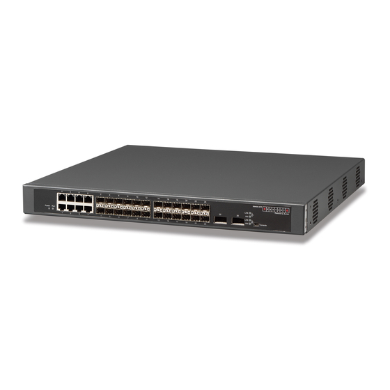
Quotation marks are not used in pairs. end of command line! 1.2.7 Fuzzy Match Support ES4624-SFP/ES4626-SFP switch shell support fuzzy match in searching command and keyword. Shell will recognize commands or keywords correctly if the entered string causes no conflict. - Page 38 and to display configuration and statistic information. Fig 1-13 Module Front Panel...
-
Page 39: Chapter 2 Basic Switch Configuration
Chapter 2 Basic Switch Configuration 2.1 Commands for Basic Switch Configuration Basic switch configuration includes commands for entering and exiting the admin mode, commands for entering and exiting port mode, for configuring and displaying the switch clock, for displaying the version information of the switch system, etc. Command Explanation Normal User Mode/ Admin Mode... -
Page 40: Commands For Basic Configuration
Configure the information displayed when the banner motd <LINE> login authentication of a telnet or console user no banner motd is successful. 2.1.1 Commands for Basic Configuration 2.1.1.1 authentication line Command:authentication line {console | vty | web| ftp} login {local | radius | tacacs} no authentication line {console | vty | web| ftp } login Function: Configure VTY (login with Telnet and ssh), Web and Console, so as to select... - Page 41 2.1.1.2 authentication ip access-class Command: authentication ip access-class {<num-std>|<name>} no authentication ip access-class Function: Binding standard IP ACL protocol to login with Telnet/SSH/Web; the no form command will cancel the binding ACL. Parameters: <num-std> is the access-class number for standard numeric ACL, ranging between 1-99;...
- Page 42 clients with trusted IP addresses are able to login the switch. Up to 32 trusted IP addresses can be configured in the switch. Example: To configure 192.168.1.21 as the trusted IP address. Switch(config)#authentication securityip 192.168.1.21 2.1.1.5 authentication securityipv6 Command:authentication securityipv6 <ipv6-addr> no authentication securityipv6 <ipv6-addr>...
- Page 43 The local users adopt username command permission while authorization command is not configured, the users login the switch via RADIUS/TACACS method and works under common mode. Example: Configure the telnet authentication mode to RADIUS. Switch(config)#authorization line vty exec radius 2.1.1.7 banner Command: banner motd <LINE>...
- Page 44 Usage Guide:This command can only be applied to the active main control boardcard, Users have to configure the first and second img files used in the next booting of the standby main control card by specifying the slot number, and can only use .img files stored in the standby main control boardcard.
- Page 45 Parameter: <HH> <MM> <SS> is the current time, and the valid scope for HH is 0 to 23, MM and SS 0 to 59; <DD> <MON> <YYYY> or <MON> <DD> <YYYY> is the current date, month and year or the current year, month and date, and the valid scope for YYYY is 1970~2038, MON meaning month, and DD between 1 to 31.
- Page 46 2.1.1.14 dir Command: dir Function: Display the files and their sizes in the Flash memory. Command mode: Admin Mode Example: Check for files and their sizes in the Flash memory. Switch#dir boot.rom 329,828 1900-01-01 00: 00: 00 --SH boot.conf 94 1900-01-01 00: 00: 00 --SH nos.img 2,449,496 1980-01-01 00: 01: 06 ---- startup-config...
- Page 47 leave the terminal for a long time. Example: Set the Admin user password to “admin”. Switch(config)#enable password 0 admin 2.1.1.17 end Command: end Function: Quit current mode and return to Admin mode when not at User Mode/ Admin Mode. Command mode: Except User Mode/ Admin Mode Example: Quit VLAN mode and return to Admin mode.
- Page 48 2.1.1.20 help Command: help Function: Output brief description of the command interpreter help system. Command mode: All configuration modes. Usage Guide: An instant online help provided by the switch. Help command displays information about the whole help system, including complete help and partial help. The user can type in ? any time to get online help.
- Page 49 Command mode: Global Mode Default: The default prompt is ES4624-SFP/ES4626-SFP switch. Usage Guide: With this command, the user can set the CLI prompt of the switch according to their own requirements. Example: Set the prompt to “Test”. Switch(config)#hostname Test Test(config)# 2.1.1.23 ip host...
- Page 50 Command mode: Admin and Config Mode. Default: The default setting is English display. Usage Guide: ES4624-SFP/ES4626-SFP switch provides help information in two languages, the user can select the language according to their preference. After the system restart, the help information display will revert to English.
- Page 51 Command mode: Global mode Default: This password is empty by system default Usage guide: When both this password and login command are configured, users have to enter the password set by password command to enter normal user mode on console Example:Switch(config)#password 0 test Switch(config)#login 2.1.1.29 ping...
- Page 52 Type ^c to abort. Sending 5 56-byte ICMP Echos to 10.1.128.160, using source address 10.1.128.161, timeout is 2 seconds. !!!!! Success rate is 100 percent (5/5), round-trip min/avg/max = 0/0/0 ms The example above shows that, the switch use 10.1.128.161 as the source address of the ICMP request messages from “ping”, and the IP address of destination device of “ping”...
- Page 53 no more than 64 characters. Default: Send 5 ICMP packets of 56 bytes each, timeout in 2 seconds. Command Mode: User Mode Usage Guide: Ping6 followed by IPv6 address is the default configuration. Ping6 function can configure the parameters of the ping packets on users’ demands. When the ipv6-address is the link-local address, a vlan interface name is needed to be specified.
- Page 54 Displayed Information Explanation ping6 Run ping6 function Target IPv6 address Destination IPv6 address Output Interface Name of Vlan interface,required to be specified when destination address is a link-local address Use source IPv6 address [n]: Use source IPv6 address, not used by default Source IPv6 address Source IPv6 IP address...
- Page 55 function however encrypted passwords remain unchanged. Example: Encrypt system passwords Switch(config)#service password-encryption 2.1.1.33 service terminal-length Command: service terminal-length <0-512> no service terminal-length Function: Configure the columns of characters displayed in each screen on terminal (vty). The “no service terminal-length” command cancels the screen shifting operation. Parameter: Columns of characters displayed on each screen of vty, ranging between 0-512.
- Page 56 2.1.1.37 setup Command: setup Function: Enter the Setup Mode of the switch. Command mode: Admin Mode Usage Guide: ES4624-SFP/ES4626-SFP switch provides a Setup Mode, in which the user can configure IP addresses, etc. 2.1.1.38 terminal length Command: terminal length <0-512>...
- Page 57 Example: Configure treads in each display to 20 Switch#terminal length 20 2.1.1.39 terminal monitor Command: terminal monitor terminal no monitor Function: Copy debugging messages to current display terminal; the “terminal no monitor” command restores to the default value Command mode: Admin mode Usage guide: Configures whether the current debugging messages is displayed on this terminal.
- Page 58 <hostname> is the name of the remote host; <hops> is the max number of the gateways the traceroute6 passed through, ranging between 1-255; <timeout> is the timeout period of the data packets,shown in millisecond and ranging between 100~10000. Default: Default number of the gateways pass by the data packets is 30, and timeout period is defaulted at 2000 ms Command Mode: Admin Mode Usage Guide: Traceroute6 is normally used to locate destination network inaccessible...
- Page 59 be denied. Example: To configure a administrator account named admin, with the preference level as 15. And configure two normal accounts with its preference level as 1. Then enable local authentication method. Above all the configurations, only the admin user is able to login the switch in privileged mode through telnet and console login method.
-
Page 60: Monitor And Debug Command
When the users configures the switch, they will need to verify whether the configurations are correct and the switch is operating as expected, and in network failure, the users will also need to diagnostic the problem. ES4624-SFP/ES4626-SFP switch provides various debug commands including ping, telnet, show and debug, etc. to help the users to check system configuration, operating status and locate problem causes. -
Page 61: Telnet
Telnet client program included in Windows or the other operation systems to login to ES4624-SFP/ES4626-SFP switch, as described earlier in the In-band management section. As a Telnet server, ES4624-SFP/ES4626-SFP switch allows up to 5 telnet client TCP connections. - Page 62 the telnet. The no form command <privilege>] [password [0|7] delete the authorized telnet user. The <password>] command privilege of the Telnet user no username <username> must set to 15. authenticaion securityip <ip-addr> Configure the secure IP address to no authentication securityip <ip-addr> login to the switch through Telnet: the authenticaion securityipv6 <ipv6-addr>...
- Page 63 2.2.3.3 Commands for Telnet 2.2.3.3.1 telnet Command: telnet [vrf <vrf-name>] {<ip-addr> | <ipv6-addr> | host <hostname>} [<port>] Function: Log on the remote host by Telnet Parameter:<vrf-name> is the specific VRF name; <ip-addr> is the IP address of the remote host,shown in dotted decimal notation; <ipv6-addr> is the IPv6 address of the remote host;...
-
Page 64: Ssh
command to enable or disable the Telnet client to login to the switch. Example: Disable the Telnet server function in the switch. Switch(config)#no ip telnet server 2.2.3.3.3 telnet-server max-connection Command:telnet-server max-connection {<max-connection-number>|default} Function:Configure the max connection number supported by the Telnet service of the switch. - Page 65 Configure the username and password of username <username> [privilege SSH client software for logging on the <privilege>] [password [0|7] switch; the no command deletes the <password>] username. no username <username> Configure timeout value authentication; “no ssh-server timeout <timeout> ssh-server timeout” command restores the default no ssh-server timeout timeout value for SSH authentication.
- Page 66 Function: Enable SSH function on the switch; the “no ssh-server enable” command disables SSH function. Command mode: Global Mode Default: SSH function is disabled by default. Usage Guide: In order that the SSH client can log on the switch, the users need to configure the SSH user and enable SSH function on the switch.
-
Page 67: Traceroute
2.2.4.3.5 ssh-server timeout Command: ssh-server timeout <timeout> no ssh-server timeout Function: Configure timeout value for SSH authentication; the “no ssh-server timeout” command restores the default timeout value for SSH authentication. Parameter: <timeout> is timeout value; valid range is 10 to 600 seconds. Command mode: Global Mode Default: SSH authentication timeout is 180 seconds by default. -
Page 68: Traceroute6
be sent. Also the send hop may be a TTL timeout return, but the procedure will carries on till the data packet is sent to its destination. These procedures is for recording every source address which returned ICMP TTL timeout message, so to describe a path the IP data packets traveled to reach the destination 2.2.6 Traceroute6 The Traceroute6 function is used on testing the gateways passed through by the... - Page 69 Show the recent command history of all users. Use clear history all-users command to clear the command history of all users show history all-users [detail] saved by the system, the max history number can be set by history all-users max-length command.
- Page 70 the system clock can be adjusted in time if inaccuracy occurs. Example: Switch#show calendar Current time is TUE AUG 22 11: 00: 01 2002] 2.2.7.1.2 show cpu usage Command: show cpu usage [<slotno>] Function: Show CPU usage rate. Command mode: Admin and configuration mode. Usage Guide: Check the current usage of CPU resource by show cpu usage command.
- Page 71 2.2.7.1.4 show history Command: show history Function: Display the recent user command history,. Command mode: Admin Mode Usage Guide: The system holds up to 19 commands the user entered, the user can use the UP/DOWN key or their equivalent (ctrl+p and ctrl+n) to access the command history. Example: Switch#show history enable...
- Page 72 Function: Display the contents in the memory. Command mode: Admin Mode Usage Guide: This command is used for switch debug purposes. The command will interactively prompt the user to enter start address of the desired information in the memory and output word number. The displayed information consists of three parts: address, Hex view of the information and character view.
- Page 73 parameters. Example: Switch#show running-config 2.2.7.1.9 show ssh-server Command: show ssh-server Function: Display SSH state and users which log on currently. Command mode: Admin Mode Example: ssh server is enabled ssh-server timeout 180s ssh-server authentication-retries 3 ssh-server max-connection number 6 ssh-server login user number 2 2.2.7.1.10 show startup-config Command: show startup-config Function: Display the switch parameter configurations written into the Flash memory at...
- Page 74 Type :Universal Mac addr num : No limit Mode: Trunk Port VID :1 Trunk allowed Vlan :ALL Displayed Information Description Ethernet1/1 Corresponding interface number of the Ethernet Type Current interface type Mac addr num Number of interfaces with MAC address learning ability Mode: Trunk Current interface VLAN mode...
- Page 75 ForeignPort Remote port number of the TCP connection. State Current status of the TCP connection. 2.2.7.1.14 show tcp ipv6 Command: show tcp ipv6 Function: Show the current TCP connection. Command mode: Admin and configuration mode. Example: Switch#show tcp ipv6 LocalAddress LocalPort RemoteAddress RemotePort State IF VRF...
-
Page 76: Debug
ForeignAddress Remote address of the udp connection. ForeignPort Remote port number of the udp connection. State Current status of the udp connection. 2.2.7.1.16 show udp ipv6 Command: show udp ipv6 Function: Show the current UDP connection. Command mode: Admin and configuration mode. Example: LocalAddress LocalPort RemoteAddress... -
Page 77: System Log
ES4624-SFP/ES4626-SFP switch supports have their corresponding debug commands. The users can use the information from debug commands for troubleshooting. Debug commands for their corresponding protocols will be introduced in the later chapters. 2.2.9 System log 2.2.9.1 System Log Introduction The system log takes all information output under it control, while making detailed catalogue, so to select the information effectively. - Page 78 buffer zone, The two buffer zone record the log information in a circuit working pattern, namely when log information need to be recorded exceeds the buffer size, the oldest log information will be erased and replaced by the new log information, information saved in NVRAM will stay permanently while those in SDRAM will lost when the system restarts or encounter an power failure.
- Page 79 Right now the switch can generate information of following four levels Restart the switch, mission abnormal, hot plug on the CHASSIS switch chips are classified critical Up/down interface, topology change, aggregate port state change of the interface are notifications warnings Outputted information from the CLI command is classified informational Information from the debugging of CLI command is classified debugging Log information can be automatically sent to corresponding channels with regard to...
- Page 80 Global Mode Enable the output channel of the logging {<ipv4-addr> | <ipv6-addr>} [ facility log host. The “no” form of this <local-number> ] [level <severity>] command will disable the output logging {<ipv4-addr> at the output channel of the log <ipv6-addr>}[ facility <local-number>] host.
- Page 81 Command Mode: Admin Mode Default: No parameter specified indicates all the critical log information will be displayed. Usage Guide: Warning and critical log information is saved in the buffer zone. When displayed to the terminal, their display format should be: index ID time <level>...
- Page 82 Usage Guide: When the old information in the log buffer zone is no longer concerned, we can use this command to clear all the information example:Clear all information in the log buffer zone sdram Switch# clear logging sdram 2.2.9.2.2.5 logging host Command: logging {<ipv4-addr>...
- Page 83 Default: Disable state. Usage Guide: After enable this command, the commands executed by user at the console, telnet or ssh terminal will record the log, so it should be used with the logging LOGHOST command. Example: Enable the command and send the commands executed by user into log host (10.1.1.1) Switch(Config)#logging 10.1.1.1 Switch(Config)#logging executed-commands enable...
-
Page 84: Reload Switch After Specified Time
Switch(Config-if-Vlan1)#ipv6 address 3ffe:506::1/64 Switch(Config-if-Vlan1)#exit Switch(config)#logging 3ffe:506::4 facility local7 level critical 2.3 Reload switch after specified time 2.3.1 Introduce to reload switch after specifid time Reload switch after specifid time is to reboot the switch without shutdown its power after a specified period of time, usually when updating the switch version. The switch can be rebooted after a period of time instead of immediately after its version being updated successfully. - Page 85 power after a specified period of time, usually when updating the switch version. The switch can be rebooted after a period of time instead of immediately after its version being updated successfully. This command will not be reserved, which means that it only has one-time effect.
-
Page 86: Debugging And Diagnosis For Packets Received And Sent By Cpu
2.4 Debugging and diagnosis for packets received and sent by CPU 2.4.1 Introduction to debugging and diagnosis for packets received and sent by CPU The following commands are used to debug and diagnose the packets received and sent by CPU, and are supposed to be used with the help of the technical support. 2.4.2 Debugging and diagnosis for packets received and sent by CPU Task List Command... -
Page 87: Commands For Debugging And Diagnosis For Packets Received And Sent By Cpu
2.4.3 Commands for debugging and diagnosis for packets received and sent by CPU 2.4.3.1 cpu-rx-ratelimit total Command: cpu-rx-ratelimit total <packets> no cpu-rx-ratelimit total Function: Set the total rate of the CPU receiving packets, the “no cpu-rx-ratelimit total” command set the total rate of the CPU receiving packets to default. Parameter:<packets>... - Page 88 Parameter: <protocol-type> is the type of the protocol, including dot1x, stp, snmp, arp, telnet, http, dhcp, igmp, ssh, bgp, bgp4plus, rip, ripng, ospf, ospfv3, pim, pimv6, unknown-mcast, unknow-mcast6, mld. <packets> is the max rate of CPU receiving packets of the protocol type, its range is <1-2000> pps. Command Mode: Global Mode Default: A different default rate is set for the different type of protocol.
-
Page 89: Configurate Switch Ip Addresses
Switch#debug driver receive 2.5 Configurate Switch IP Addresses All Ethernet ports of ES4624-SFP/ES4626-SFP switch is default to Data Link layer ports and perform layer 2 forwarding. VLAN interface represent a Layer 3 interface function which can be assigned an IP address, which is also the IP address of the switch. -
Page 90: Commands For Configuring Switch Ip
1. Manual configuration 2. BOOTP configuration 3. DHCP configuration 1. Manual configuration Command Explanation Configure the VLAN interface IP address; address <ip_address> <mask> the “no ip address <ip_address> <mask> [secondary] [secondary]” command deletes VLAN no ip address <ip_address> <mask> interface IP address. [secondary] 2. - Page 91 mask in dot decimal format; [secondary] indicates the IP configured is a secondary IP address. Default: No IP address is configured upon switch shipment. Command mode: Port mode Usage Guide: A VLAN interface must be created first before the user can assign an IP address to the switch.
-
Page 92: Snmp Configuration
mutually exclusive, enabling any 2 methods for obtaining an IP address is not allowed. Example: Getting an IP address through DHCP. Switch (config)#interface vlan 1 Switch (Config-if-Vlan1)#ip address dhcp-client 2.6 SNMP Configuration 2.6.1 Introduction To SNMP SNMP (Simple Network Management Protocol) is a standard network management protocol widely used in computer network management. -
Page 93: Introduction To Mib
requests, replies with Get-Response message. On some special situations, like network device ports are on Up/Down status or the network topology changes, Agents can send Trap messages to NMS to inform the abnormal events. Besides, NMS can also be set to alert to some abnormal events by enabling RMON function. -
Page 94: Introduction To Rmon
Fig 2-1 ASN.1 Tree Instance In this figure, the OID of the object A is 1.2.1.1. NMS can locate this object through this unique OID and gets the standard variables of the object. MIB defines a set of standard variables for monitored network devices by following this structure. If the variable information of Agent MIB needs to be browsed, the MIB browse software needs to be run on the NMS. -
Page 95: Snmp Configuration Task List
the Agent. History: Record periodical statistic samples available from Statistics. Alarm: Allow management console users to set any count or integer for sample intervals and alert thresholds for RMON Agent records. Event: A list of all events generated by RMON Agent. Alarm depends on the implementation of Event. - Page 96 {<ipv6-num-std>|<ipv6-name>}] 3. Configure IP address of SNMP management base Command Explanation Configure the secure IPv4/IPv6 address snmp-server securityip which is allowed to access the switch on {<ipv4-address>| <ipv6-address>} the NMS; the “no snmp-server securityip snmp-server securityip {<ipv4-address>| <ipv6-address>} {<ipv4-address> command deletes <ipv6-address>}“...
-
Page 97: Commands For Snmp
[ipv6-access {<ipv6-num-std>|<ipv6-name>}] 7. Configure view Command Explanation Configure view switch. This snmp-server view <view-string> command is used for SNMP v3. <oid-string> {include|exclude} no snmp-server view <view-string> 8. Configuring TRAP Command Explanation Enable the switch to send Trap message. snmp-server enable traps This command is used for SNMP v1/v2/v3. - Page 98 Switch(config)#rmon enable Example 2: Disable RMON Switch(config)#no rmon enable 2.6.5.2 show snmp Command: show snmp Function: Display all SNMP counter information. Command mode: Admin Mode Example: Switch#show snmp 0 SNMP packets input 0 Bad SNMP version errors 0 Unknown community name 0 Illegal operation for community name supplied 0 Encoding errors 0 Number of requested variables...
- Page 99 number of altered variables Number of variables set by NMS. get-request PDUs Number of packets received by “get” requests. get-next PDUs Number of packets received by “getnext” requests. set-request PDUs Number of packets received by “set” requests. snmp packets output Total number of SNMP packet outputs.
- Page 100 V3 Trap Host Information: Displayed information Description Community string Community string Community access Community access permission Trap-rec-address IP address which is used to receive Trap. Trap enable Enable or disable to send Trap. SecurityIP IP address of the NMS which is allowed to access Agent 2.6.5.4 snmp-server community Command:...
- Page 101 specifically readable view or writable view. Example: Add a community string named “private” with read-write permission. Switch(config)#snmp-server community private rw Add a community string named “public” with read-only permission. Switch(config)#snmp-server community public ro Modify the read-write community string named “private” to read-only. Switch(config)#snmp-server community private ro Delete community string “private”.
- Page 102 Switch(config)#snmp-server enable traps Example 2: Disable to send Trap messages. Switch(config)#no snmp-server enable traps 2.6.5.7 snmp-server host Command: snmp-server host {<ipv4-addr> | <ipv6-addr>} {v1 | v2c | {v3 {NoauthNopriv | AuthNopriv | AuthPriv}}} <user-string> no snmp-server host {<ipv4-addr> | <ipv6-addr>} {v1 | v2c | {v3 {NoauthNopriv | AuthNopriv | AuthPriv}}} <user-string>...
- Page 103 Command: debug snmp mib no debug snmp mib Function: Enable the SNMP mib debugging; the "no debug snmp mib” command disables the debugging Command Mode: Admin Mode Usage Guide: When user encounters problems in applying SNMP, the SNMP debugging is available to locate the problem causes. Example: Switch#debug snmp mib 2.6.5.9 debug snmp kernel Command: debug snmp kernel...
- Page 104 SNMP engineID Engine number Engine Boots Engine boot counts 2.6.5.12 show snmp group Command: show snmp group Function: Display the group information commands Command Mode: Admin Mode Example: Switch#show snmp group Group Name:initial Security Level:noAuthnoPriv Read View:one Write View:<no writeview specified> Notify View:one Displayed Information Explanation...
- Page 105 User name User name Engine ID Engine ID Priv Protocol Employed encryption algorithm Auth Protocol Employed identification algorithm Row status User state 2.6.5.15 show snmp view Command: show snmp view Function: Display the view information commands. Command Mode: Admin Mode Example: Switch#show snmp view View Name:readview...
- Page 106 Command: snmp-server group <group-string> {NoauthNopriv|AuthNopriv|AuthPriv} [[read <read-string>] [write <write-string>] [notify <notify-string>]] [access {<num-std>|<name>}] [ipv6-access {<ipv6-num-std>|<ipv6-name>}] snmp-server group <group-string> {NoauthNopriv|AuthNopriv|AuthPriv} [access {<num-std>|<name>}] [ipv6-access {<ipv6-num-std>|<ipv6-name>}] Function: This command is used to configure a new group; the “no” form of this command deletes this group. Command Mode: Global Mode Parameter:<group-string >...
- Page 107 Default:Enable the safety IP address authentication function Example: Disable the safety IP address authentication function Switch(config)#snmp-server securityip disable 2.6.5.19 snmp-server trap-source Command: snmp-server trap-source {<ipv4-address> | <ipv6-address>} no snmp-server trap-source {<ipv4-address> | <ipv6-address>} Function: Set the source IPv4 or IPv6 address which is used to send trap packet, the no command deletes the configuration.
- Page 108 Create a view, the name is readview, including iso node but not including the iso.3 node Switch (config)#snmp-server view readview iso include Switch (config)#snmp-server view readview iso.3 exclude Delete the view Switch (config)#no snmp-server view readview 2.6.5.21 snmp-server user Command: snmp-server user <use-string> <group-string> [{authPriv | authNoPriv} auth {md5 sha}...
-
Page 109: Typical Snmp Configuration Examples
Switch (config)#snmp-server user tester UserGroup authPriv auth md5 hellohello deletes an User Switch (config)#no snmp-server user tester UserGroup 2.6.5.22 snmp-server securityip Command:snmp-server securityip {<ipv4-address>| <ipv6-address>} no snmp-server securityip {<ipv4-address>| <ipv6-address>} Function: Configure to permit to access security IPv4 or IPv6 address of the switch administration station;... -
Page 110: Snmp Troubleshooting
data from the switch. The configuration on the switch is listed below: Switch(config)#snmp-server Switch(config)#snmp-server community private rw Switch(config)#snmp-server community public ro Switch(config)#snmp-server securityip 1.1.1.5 The NMS can use “private” as the community string to access the switch with read-write permission, or use “public” as the community string to access the switch with read-only permission. -
Page 111: Switch Upgrade
If users still can’t solve the SNMP problems, Please contact our technical and service center. 2.7 Switch Upgrade ES4624-SFP/ES4626-SFP switch provides two ways for switch upgrade: BootROM upgrade and the TFTP/FTP upgrade under Shell. 2.7.1 Switch System Files The system files includes system image file and boot file. The updating of the switch is to update the two files by overwrite the old files with the new ones. -
Page 112: Bootrom Upgrade
2.7.2 BootROM Upgrade There are two methods for BootROM upgrade: TFTP and FTP, which can be selected at BootROM command settings. cable Console cable connection connection Fig 2-3 Typical topology for switch upgrade in BootROM mode The upgrade procedures are listed below: Step 1: As shown in the figure, a PC is used as the console for the switch. - Page 113 BootRom version: 1.0.4 Creation date: Jun 9 2006, 14: 54: 12 Attached TCP/IP interface to lnPci0. [Boot]: Step 3: Under BootROM mode, run “setconfig” to set the IP address and mask of the switch under BootROM mode, server IP address and mask, and select TFTP or FTP upgrade. Suppose the switch address is 192.168.1.2/24, and PC address is 192.168.1.66/24, and select TFTP upgrade, the configuration should like: [Boot]: setconfig...
-
Page 114: Ftp/Tftp Upgrade
[Boot]: Step 6: After successful upgrade, execute “run” command in BootROM mode to return to CLI configuration interface. [Boot]: run(or reboot) Other commands in BootROM mode DIR command Used to list existing files in the FLASH. [Boot]: dir boot.rom 327,440 1900-01-01 00: 00: 00 --SH boot.conf 83 1900-01-01 00: 00: 00 --SH nos.img... - Page 115 And file list can also be retrieved from the server in ftp client mode. Of course, ES4624-SFP/ES4626-SFP switch can also upload current configuration files or system files to the remote FTP/TFTP servers(can be hosts or other switches).
- Page 116 Boot file: refers to the file initializes the switch, also referred to as the ROM upgrade file (Large size file can be compressed as IMAGE file). In ES4624-SFP/ES4626-SFP switch, the boot file is allowed to save in ROM only. ES4624-SFP/ES4626-SFP switch mandates the name of the boot file to be boot.rom.
- Page 117 2. FTP server configuration (1) Start FTP server (2) Configure FTP login username and password (3) Modify FTP server connection idle time (4) Shut down FTP server 3. TFTP server configuration (1) Start TFTP server (2) Configure TFTP server connection idle time (3)...
- Page 118 Global Mode Start TFTP server, the “no ftp-server enable” tftp-server enable command shuts down TFTP server and no tftp-server enable prevents TFTP user from logging in. (2)Modify TFTP server connection idle time Command Explanation Global Mode tftp-server Set maximum retransmission time within retransmission-timeout timeout interval.
- Page 119 running-config startup-config command System files nos.img System startup files nos.rom Command Mode: Admin Mode Usage Guide: This command supports command line hints,namely if the user can enter commands in following forms: copy <filename> ftp:// or copy ftp:// <filename> and press Enter,following hints will be provided by the system: ftp server ip/ipv6 address [x.x.x.x]/[x:x::x:x] >...
- Page 120 Running configuration files running-config It means the reboot configuration files when using copy startup-config running-config startup-config command System files nos.img System startup files nos.rom Command Mode: Admin Mode Usage Guide: This command supports command line hints,namely if the user can enter commands in following forms: copy <filename>...
- Page 121 Default: FTP server is not started by default. Command mode: Global Mode Usage Guide: When FTP server function is enabled, the switch can still perform ftp client functions. FTP server is not started by default. Example: enable FTP server service. Switch#config Switch(config)# ftp-server enable 2.7.3.2.2.5 ftp-server timeout...
- Page 122 Example: Switch#show tftp timeout : 60 Retry Times : 10 Displayed information Explanation Timeout Timeout time. Retry Times Retransmission times. 2.7.3.2.2.8 tftp-server enable Command: tftp-server enable no tftp-server enable Function: Start TFTP server, the “no ftp-server enable” command shuts down TFTP server and prevents TFTP user from logging in.
-
Page 123: Ftp/Tftp Configuration Examples
Switch#config Switch(config)#tftp-server transmission-timeout 60 2.7.4 FTP/TFTP Configuration Examples It is the same configuration switch for IPv4 addresses and IPv6 addresses. The example only for the IPv4 addresses configuration. Switch 10.1.1.2 computer 10.1.1.1 Fig 2-4 Download nos.img file as FTP/TFTP client Scenario 1: The switch is used as FTP/TFTP client. - Page 124 downloaded to the FLASH. TFTP Configuration Computer side configuration: Start TFTP server software on the computer and place the “nos.img” file to the appropriate TFTP server directory on the computer. The configuration procedures of the switch is listed below: Switch(config)#interface vlan 1 Switch(Config-if-Vlan1)#ip address 10.1.1.2 255.255.255.0 Switch(Config-if-Vlan1)#no shut Switch(Config-if-Vlan1)#exit...
- Page 125 Computer side configuration: Login to the switch with any TFTP client software, use the “tftp” command to download “nos.img” file from the switch to the computer. Scenario 4: The switch is used as FTP/TFTP client. The switch connects from one of its ports to a computer, which is a FTP/TFTP server with an IP address of 10.1.1.1;...
-
Page 126: Ftp/Tftp Troubleshooting
Switch#copy tftp: //10.1.1.1/ startup-config startup-config Scenario 5: ES4624-SFP/ES4626-SFP switch acts as FTP client to view file list on the FTP server. Synchronization conditions: The switch connects to a computer by an Ethernet port, the computer is a FTP server with an IP address of 10.1.1.1; the switch acts as a FTP client, and the IP address of the switch management VLAN1 interface is 10.1.1.2. - Page 127 2.7.5.1 FTP Troubleshooting When upload/download system file with FTP protocol, the connectivity of the link must be ensured, i.e., use the “Ping” command to verify the connectivity between the FTP client and server before running the FTP program. If ping fails, you will need to check for appropriate troubleshooting information to recover the link connectivity.
-
Page 128: Jumbo Configuration
check for appropriate troubleshooting information to recover the link connectivity. The following is the message displays when files are successfully transferred. Otherwise, please verify link connectivity and retry “copy” command again. nos.img file length = 1526021 read file ok begin to send file,wait... file transfers complete. -
Page 129: Jumbo Command
1.Configure enable Jumbo function Command Explanation Enable/disable sending/receiving function jumbo enable [<mtu-value>] of the Jumbo frames no jumbo enable 2.8.3 Jumbo Command Command:jumbo enable [<mtu-value>] no jumbo enable Function: Configure the MTU size of JUMBO frame, enable the Jumbo receiving/sending function. -
Page 130: Sflow Configuration Task
sFlow system. We have achieved data sampling and statistic targeting physical port. Our data sample includes the IPv4 and IPv6 packets. Extensions of other types are not supported so far. As for non IPv4 and IPv6 packet, the unify HEADER mode will be adopted following the requirements in RFC3176, copying the head information of the packet based on analyzing the type of its protocol. -
Page 131: Commands For Sflow
priority” command restores to the default 4. Configure the packet head length copied by sFlow Command Explanation Port mode Configure the length of the packet data sflow header-len <length-vlaue> head copied in the sFlow data sampling; no sflow header-len the “no” form of this command restores to the default value. - Page 132 Command: sflow destination <collector-address> [<collector-port>] no sflow destination Function: Configure the IP address and port number of the host on which the sFlow analysis software is installed. If the port has been configured with IP address, the port configuration will be applied, or else the global configuration will be applied. The “no” form of this command restores the port to default and deletes the IP address.
- Page 133 Command Mode: Global Mode Default: Do not configure. Usage Guide: Configure this command when using sFlowTrend. Example: Switch(config)#sflow analyzer sflowtrend 2.9.3.4 sflow priority Command: sflow priority <priority-value> no sflow priority Function: Configure the priority when sFlow receives packet from the hardware. The "no”...
- Page 134 no sflow data-len Function: Configure the max length of the sFlow packet data; the “no sflow data-len” command restores to the default value Parameter: <length-value> is the value of the length with a valide range of 500-1470 Command Mode: Port mode Default: The value is 1400 by default Usage Guide: When combining several samples to a sFlow group to be sent, the length of the group excluding the mac head and IP head parts should not exceed the configured...
- Page 135 configured on the port. And if the ingress group sampling rate is set to 10000, this indicates there will be one group be sampled every 10000 ingress groups. Example: Configure the ingress sample rate on port e3/1 to 10000 and the egress sample rate to 20000 Switch(Config-If-Ethernet3/2)#sflow rate input 10000 Switch(Config-If-Ethernet3/2)#sflow rate output 20000...
-
Page 136: Sflow Examples
Collector address The analyzer address of the sampling address of the 192.168.1.200 E3/1 interface is 192.168.1.200 Collector port is 6343 Default value of the port on E3/1 interface sampling proxy is 6343. Counter interval is 20 The statistic sampling interval on e3/1 interface is 20 seconds Sample rate is input 10000, The ingress traffic rate of e3/1 interface sampling proxy... -
Page 137: Sflow Troubleshooting
Switch (Config-If-Ethernet3/1)#sflow counter-interval 20 Switch (Config-If-Ethernet3/1)#exit Switch (config)# interface ethernet3/2 Switch (Config-If-Ethernet3/2)#sflow rate input 20000 Switch (Config-If-Ethernet3/2)#sflow rate output 20000 Switch (Config-If-Ethernet3/2)#sflow counter-interval 40 2.9.5 sFlow Troubleshooting In configuring and using sFlow, the sFlow server may fail to run properly due to physical connection failure, wrong configuration, etc. -
Page 138: Commands For Tacacs
Configure the TACACS+ authentication key Configure the TACACS+ server Configure the TACACS+ authentication timeout time Configure the IP address of the RADIUS NAS 1) Configure the TACACS+ authentication key Command Explanation Global Mode Configure the TACACS+ server key; the tacacs-server key <string> “no command tacacs-server... - Page 139 Command: tacacs-server authentication host <ip-address> [port <port-number>] [timeout <seconds>] [key <string>] [primary] no tacacs-server authentication host <ip-address> Function: Configure the IP address, listening port number, the value of timeout timer and the key string of the TACACS+ server; the “no” form of this command deletes TACACS+ authentication server.
- Page 140 TACACS+ server or else no correct TACACS+ authentication will be performed. It is recommended to configure the authentication server key to ensure the data security. Example: Configure test as the TACACS+ server authentication key. Switch(config)# tacacs-server key test 2.10.3.3 tacacs-server nas-ipv4 Command: tacacs-server nas-ipv4 <ip-address>...
-
Page 141: Typical Tacacs+ Scenarios
Example: Configure the timeout timer of the tacacs+ server to 30 seconds Switch(config)# tacacs-server timeout 30 2.10.3.5 debug tacacs-server Command: debug tacacs-server no debug tacacs-server Function: Open the debug message of the TACACS+; the “no debug tacacs-server” command closes the TACACS+ debugging messages. Command Mode: Admin Mode Parameter: None Usage Guide: Enable the TACACS+ debugging messages to check the negotiation... -
Page 142: Radius Configuration
In configuring and using TACACS+, the TACACS+ may fail to authentication due to reasons such as physical connection failure or wrong configurations. The user should ensure the following: First good condition of the TACACS+ server physical connection Second all interface and link protocols are in the UP state (use “show interface” command) Then ensure the TACACS+ key configured on the switch is in accordance with the one configured on TACACS+ server... - Page 143 Fig 2-7 Message structure for RADIUS Codefield(1octets): is the type of the RADIUS packet. Available value for the Code field is show as below: 1 Access-Request 2 Access-Accept 3 Access-Reject 4 Accounting-Request 5 Accounting-Response 11 Access-Challenge Identifier field (1 octet) : Identifier for the request and answer packets. Length field (2 octets) : The length of the overall RADIUS packet, including Code, Identifier, Length, Authenticator and Attributes Authenticator field (16 octets): used for validation of the packets received from the...
-
Page 144: Radius Configuration
CHAP-Password Class NAS-IP-Address Vendor-Specific NAS-Port Session-Timeout Service-Type Idle-Timeout Framed-Protocol Termination-Action Framed-IP-Address Called-Station-Id Framed-IP-Netmask Calling-Station-Id Framed-Routing NAS-Identifier Filter-Id Proxy-State Framed-MTU Login-LAT-Service Framed-Compression Login-LAT-Node Login-IP-Host Login-LAT-Group Login-Service Framed-AppleTalk-Link Login-TCP-Port Framed-AppleTalk-Network (unassigned) Framed-AppleTalk-Zone Reply-Message 40-59 (reserved for accounting) Callback-Number CHAP-Challenge Callback-Id NAS-Port-Type (unassigned) Port-Limit Framed-Route Login-LAT-Port... - Page 145 Command Explanation Global Mode enable authentication function. The no form of this command aaa enable will disable the AAA authentication no aaa enable function. To enable AAA accounting. The no form aaa-accounting enable of this command will disable AAA no aaa-accounting enable accounting.
-
Page 146: Commands For Radius
Command Explanation Global Mode configure interval that RADIUS becomes available after it is radius-server dead-time <minutes> down. The no form of this command will no radius-server dead-time restore the default configuration. To configure retry times for the RADIUS radius-server retransmit <retries> packets. - Page 147 Usage Guide: The AAA authentication for the switch must be enabled first to enable IEEE 802.1x authentication for the switch. Example: Enable AAA function for the switch. Switch(config)#aaa enable 2.11.3.2 aaa-accounting enable Command: aaa-accounting enable no aaa-accounting enable Function: Enables the AAA accounting function in the switch: the "no aaa-accounting enable"...
- Page 148 Function: Enable the debug information of aaa about receiving and sending packets; the no operation of this command will disable such debug information. Parameters:send:Enable the debug information of aaa about sending packets. receive:Enable the debug information of aaa about receiving packets. all:Enable the debug information of aaa about both sending and receiving packets.
- Page 149 Parameters:None. Command Mode:Admin Mode. Usage Guide:By enabling the debug information of aaa about connection details, users can check connection details of aaa, which might help diagnose the cause of faults if there is any. Example:Enable the debug information of aaa about connection details Switch#debug aaa detail connection 2.11.3.7 debug aaa detail event Command:debug aaa detail event...
- Page 150 “no radius nas-ipv4” command delete the configuration. Parameter: <ip-address> is the source IP address of the RADIUS packet, in dotted decimal notation, it mast be a valid unicast IP address. Default: No specific source IP address for RADIUS packet is configured, the IP address of the interface from which the RADIUS packets are sent is used as source IP address of RADIUS packet.
- Page 151 Function: Specifies the IPv4/IPv6 address and the port number, whether be primary server for RADIUS accounting server; the no command deletes the RADIUS accounting server. Parameters: <ipv4-address> | <ipv6-address> stands for the server IPv4/IPv6 address; <port-number> for server listening port number from 0 to 65535; <string>...
- Page 152 would be available. RADIUS Server will be searched by the configured order if primary is not configured, otherwise, the specified RADIUS server will be used last. [access-mode {dot1x|telnet}] designates the current RADIUS server only use 802.1x authentication or telnet authentication, all services can use current RADIUS server by default.
- Page 153 Example: Setting the down-restore time for RADIUS server to 3 minutes. Switch(config)#radius-server dead-time 3 2.11.3.14 radius-server key Command:radius-server key <string> no radius-server key Function: Specifies the key for the RADIUS server (authentication and accounting); the “no radius-server key” command deletes the key for RADIUS server. Parameters: <string>...
- Page 154 no radius-server timeout Function: Configures the timeout timer for RADIUS server; the “no radius-server timeout” command restores the default setting. Parameters: <seconds> is the timer value (second) for RADIUS server timeout, the valid range is 1 to 1000. Command mode: Global Mode Default: The default value is 3 seconds.
- Page 155 messages(in seconds) 300(default value) 1~299 300~599 600~1199 1200 1200~1799 1800 ≥1800 3600 Example:The maximum number of users supported by NAS is 700, the interval of sending fee-counting update messages 1200 seconds. Switch(config)#radius-server accounting-interim-update timeout 1200 2.11.3.18 show aaa authenticated-user Command: show aaa authenticated-user Function: Displays the authenticated users online.
- Page 156 2.11.3.20 show aaa config Command: show aaa config Function: Displays the configured commands for the switch as a RADIUS client. Command mode: Admin Mode Usage Guide: Displays whether AAA authentication, accounting are enabled and information for key, authentication and accounting server specified. Example: Switch#show aaa config(For Boolean value, 1 stands for TRUE and 0 for FALSE)...
- Page 157 Displayed information Description Is AAA Enabled Indicates whether AAA authentication is enabled or not. 1 for enable and 0 for disable. Is Account Enabled Indicates whether AAA accounting is enabled or not. 1 for enable and 0 for disable. MD5 Server Key Displays the key for RADIUS server.
-
Page 158: Radius Typical Example
Switch #show radius authencated-user count --------------------- Radius user statistic--------------------- The authencated online user num is: The total user num is: 2. Display the statistics for RADIUS authenticated users and others. Switch #sho radius authencating-user count --------------------- Radius user statistic--------------------- The authencating user num is: The stopping user num is: The stopped user num is: The total user num is:... -
Page 159: Radius Troubleshooting
Switch(config)#aaa enable Switch(config)#aaa-accounting enable 2.11.4.2 IPv6 RadiusExample Fig 2-9 The Topolopy of IPv6 Radius configuration A computer connects to a switch, of which the IP address is 2004:1:2:3::2 and connected with a RADIUS authentication server; IP address of the server is 2004:1:2:3::3 and the authentication port is defaulted at 1812, accounting port is defaulted at 1813. -
Page 160: Web Management
Finally ensure to connect to the correct RADIUS server. 2.12 Web Management 2.12.1 Switch Basic Configuration Users should click “Switch basic configuration” table and configure the switch’s clock, prompts of command-line interface, timeout of quitting Admin mode, etc. 2.12.1.1 Basic Configuration Users should click “Switch basic configuration”... -
Page 161: Snmp Configuration
2.12.2 SNMP Configuration Users should click “Switch basic configuration” and “SNMP configuration” to configure the SNMP relating functions. 2.12.2.1 SNMP Manager Configuration Users should click “Switch basic configuration”, “SNMP configuration”, and “SNMP manager configuration” to configure the community string of the switch. Community string (0-255 characters) -for configuration of the community string. - Page 162 2.12.2.3 Configure IP address of SNMP manager User should click “Switch basic configuration”, “SNMP configuration”, and “Configure ip address of snmp manager” to configure the security IP address which will be allowed to access to the NMS management station of the switch. 5.4.4.2.6. Security ip address -Security IP address of NMS State –”Valid”...
-
Page 163: Switch Upgrade
2.12.2.5 RMON and trap configuration Users should click “Switch basic configuration”, “SNMP configuration” and “RMON and TRAP configuration” to configure the RMON function of the switch. Snmp Agent state –open/close the switch to be SNMP agent server function. RMON state -open/close RMON function of the switch. Trap state -allows device to send Trap messages Example: choose Snmp Agent state as “Open”, choose RMON state as “Open”, and choose Trap state as “Open”. - Page 164 FTP client service -to configure FTP client FTP server service -to configure FTP server 2.12.3.1 TFTP client configuration Users should click “Switch basic configuration” and “TFTP client service” to enter into the configuration page. Words and phrases are explained in the following: Server IP address-IP address of the server.
- Page 165 2.12.3.3 FTP client configuration Users should click “Switch basic configuration” and “FTP client service” to enter into this configuration page. Words and phrases are explained in the following: Server IP address-IP address of the server User name-the name of the user Password-the specific password Operation type-”Upload”...
-
Page 166: Monitor And Debug Command
Example: open the TFTP server, input the username “switch” and password “switch”, and then click “Apply.” 2.12.4 Monitor And Debug Command Users should click “Switch basic configuration” and “Basic configuration debug” to enter into the configuration page and make configuration nodes, which include the following segments: Debug command-a debugging command. -
Page 167: Switch Maintenance
2.12.4.2 Show vlan port property Users should click “Switch basic configuration”, “Basic configuration debug” and “show switchport interface” to enter into the configuration page and make configuration nodes. “Port” means the port table. Example: User finds a VLAN port’s properties by choosing port1/1 and click “Apply.” 2.12.4.3 Others Other parts are easier to configure. -
Page 168: Telnet Server Configuration
Users should save the current running-config by clicking “Switch maintenance”, “Save current running-config” and “Apply”. 2.12.5.3 Reboot Users should reboot the switch by clicking “Switch maintenance.” 2.12.5.4 Reboot with the default configuration Users should clear all current configurations and reboot the switch again by clicking “Switch maintenance”... -
Page 169: Radius Client Configuration
Users should click “Telnet server configuration” and “Telnet security IP” to configure the security IP address of an allowed Telnet client for when the switch functions as the Telnet server. Words and phrases are explained in the following: Security IP address-a specific security IP address Operation-to choose from the drop-down list. - Page 170 Accounting Status as Enable Accounting, configure RADIUS key as “aaa”, configure System recovery time as 10 seconds, configure RADIUS Retransmit times as 5 times, configure RADIUS server timeout as 30 seconds, and lastly, click Apply button. The configuration will then be applied to the switch. 2.12.9.2 RADIUS authentication configuration Click “Authentication configuration”, “RADIUS client configuration”, “RADIUS authentication configuration”...
- Page 171 Click “Authentication configuration”, “RADIUS client configuration”, “RADIUS accounting configuration” to configure the RADIUS accounting server’s IP address and monitor port Accounting server IP - server IP address. Accounting server port(optional) -is the accounting server port ID, with range: 0~65535, where “0” means that it’s not work as authentication server. Primary accounting server -Primary Accounting server, is the primary server;...
-
Page 172: Chapter 3 Port Configuration
Chapter 3 Port Configuration 3.1 Introduction to Port ES4624-SFP/ES4626-SFP Switch comes with 8 Gigabit Combo ports , 16 SFP Gigabit fiber ports and (for ES4626-SFP) 2 SFP 10G fiber ports. The Combo ports can be configured to as either 1000GX-TX ports or Gigabit fiber ports. - Page 173 (9) Configure broadcast storm control function for the switch (10) Configure the scan mode of the port (11) Configure rate-violation control of the port (12) Configure interval of port-rate-statistics 1. Enter the Ethernet port configuration mode Command Explanation Port mode Enters the network port configuration interface ethernet <interface-list>...
- Page 174 Enables/Disables traffic control function for flow control specified ports no flow control Enables/Disables loopback test function loopback for specified ports no loopback Enables the storm control function for broadcasts, multicasts and unicasts with unknown destinations (short rate-suppression {dlf | broadcast | broadcast), sets allowed...
- Page 175 Usage Guide: The combo mode of combo ports and the port connection condition determines the active port of the combo ports. A combo port consists of one fiber port and a copper cable port. It should be noted that the speed-duplex command applies to the copper cable port while the negotiation command applies to the fiber cable port, they should not conflict.
- Page 176 Usage Guide: After the flow control function is enabled, the port will notify the sending device to slow down the sending speed to prevent packet loss when traffic received exceeds the capacity of port cache. ES4624-SFP/26-SFP’s ports support IEEE802.3X flow control; the ports work in half-duplex mode, supporting back-pressure flow control. If...
- Page 177 flow control results in serious HOL, the switch will automatically start HOL control (discarding some packets in the COS queue that may result in HOL) to prevent drastic degradation of network performance. Note: Port flow control function is NOT recommended unless the users need a slow speed, low performance network with low packet loss.
- Page 178 This command is not supported on ES4624-SFP/26-SFP’s ports of 1000Mbps or more, these ports have auto-identification set for cable types. Parameters: auto indicates auto identification of cable types; across indicates crossover cable support only; normal indicates straight-through cable support only.
- Page 179 Command Mode: Global Mode Usage Guide: None. Example: Count the interval of port-rate-statistics as 20 seconds. Switch(config)#port-rate-statistics interval 20 3.2.1.2.10 port-scan-mode Command: port-scan-mode {interrupt | poll} no port-scan-mode Function: Configure the scan mode of the port as “interrupt” or “poll”, the no command restores the default scan mode.
- Page 180 port. For example, an 10/100M Ethernet port can not be set to a bandwidth limit at 101M (or higher), but applicable on a 10/100/1000 port working at a speed of 100M. If the actual bandwidth is not a integral multiple of chip bandwidth granularity, it will be modified automatically.
- Page 181 3.2.1.2.13 rate-violation Command: rate-violation <200-2000000> [recovery <0-86400>|] no rate-violation Function: Set the max packet reception rate of a port. If the rate of the received packet violates the packet reception rate, shut down this port and configure the recovery time, the default is 300s.
- Page 182 counter {packet | rate} show package number or rate statistics of all layer 2 ports. <port-channel-number> is the number of the aggregation interface, <interface-name> is the name of the interface such as port-channel1. [detail] show the detail of the port. Command Mode: Admin and Configuration Mode.
- Page 183 Input packets statistics: Input queue 0/600, 0 drops 0 packets input, 0 bytes, 0 no buffer 0 input errors, 0 CRC, 0 frame alignment, 0 overrun 0 ignored, 0 abort, 0 length error Output packets statistics: 0 packets output, 0 bytes, 0 underruns 0 output errors, 0 collisions, 0 late collisions Show the information of loopback 1: Switch#show interface loopback 1...
- Page 184 The last 5 second output rate 0 bytes/sec, 0 packets/sec Input packets statistics: Input queue 0/600, 0 drops 0 packets input, 0 bytes, 0 no buffer 0 input errors, 0 CRC, 0 frame alignment, 0 overrun 0 ignored, 0 abort, 0 length error Output packets statistics: 0 packets output, 0 bytes, 0 underruns 0 output errors, 0 collisions, 0 late collisions...
- Page 185 1/1 UP/UP f-100M f-full 1 G-TX 1/2 UP/UP a-100M a-full trunk G-TX 1/3 UP/DOWN auto auto 1 G-TX 1/4 A-Down/DOWN auto auto 1 G-TX … Show the package number statistics information of all layer 2 ports: Switch#Show interface ethernet counter packet Interface Unicast(pkts) BroadCast(pkts) MultiCast(pkts) Err(pkts) 1/1 IN 12,345,678 12,345,678,9 12,345,678,9 4,567 OUT 23,456,789 34,567,890 5,678 0...
- Page 186 the port status displayed when the user types the “show interface” command is “down”. Example: Opening ports 1/1-8. Switch(config)#interface ethernet1/1-8 Switch(Config-Port-Range)#no shutdown 3.2.1.2.16 speed-duplex Command: speed-duplex {auto [10 [100 [1000]] [auto | full | half |]] | force10-half | force10-full | force100-half | force100-full | force100-fx [module-type {auto-detected | no-phy-integrated | phy-integrated}] | {{force1g-half | force1g-full} [nonegotiate [master | slave]]}| force10g-full} no speed-duplex...
-
Page 187: Vlan Interface Configuration
SwitchA(config)#interface ethernet1/1 SwitchA(Config-If-Ethernet1/1)#speed-duplex force100-half SwitchB(config)#interface ethernet1/1 SwitchB(Config-If-Ethernet1/1)#speed-duplex force100-half 3.2.2 VLAN Interface Configuration 3.2.2.1 VLAN Interface Configuration Task List Enter VLAN Mode Configure the IP address for VLAN interface and enable VLAN interface. 1. Enter VLAN Mode Command Explanation Global Mode Enters VLAN Port mode;... - Page 188 existing VLAN interface. Parameters: <vlan-id> is the VLAN ID for the establish VLAN, the valid range is 1 to 4094. Command mode: Global Mode Usage Guide: Before setting a VLAN interface, the existence of the VLAN must be verified. Run the exit command to exit the VLAN Mode to Global Mode. Example: Entering into the Port mode for VLAN1.
-
Page 189: Network Management Port Configuration
protocol, it must be enabled. Example: Enabling VLAN1 interface of the switch. Switch(Config-if-Vlan1)#no shutdown 3.2.3 Network Management Port Configuration 3.2.3.1 Network Management Port Configuration Task List 1. Enter the network management port configuration mode 2. Configure the properties for the network management ports (1)... - Page 190 3.2.3.2.1 duplex Command: duplex {auto| full| half } Function: Sets network management port duplex mode Parameters: auto for auto-negotiation full-duplex mode; full for forced full-duplex mode; half for forced half-duplex mode. Command mode: Network management port configuration Mode Default: The default duplex mode is set to auto-negotiation. Usage Guide: According to IEEE 802.3, the auto-negotiation for port speed and duplex are linked.
- Page 191 Default: No IP address is configured by default. Usage Guide: This command configures the IP address for network management port. Example: Setting the IP address of the network management interface to 192.168.1.10/24. Switch(Config-If-Ethernet0)#ip address 192.168.1.10 255.255.255.0 3.2.3.2.4 shutdown Command: shutdown no shutdown Function: Shuts down the network management port;...
-
Page 192: Port Mirroring Configuration
3.3 Port Mirroring Configuration 3.3.1 Introduction to Port Mirroring Port mirroring refers to the duplication of data frames sent/received on a port to another port. The duplicated port is referred to as mirror source port and the duplicating port is referred to as mirror destination port. A protocol analyzer (such as Sniffer) or RMON monitoring instrument is often attached to the mirror destination port to monitor and manage the network and diagnostic. -
Page 193: Device Mirroring Troubleshooting
Function: Specifies port of mirror source; the “no port monitor interface <interface-list>” command deletes the mirror source port. Parameter: <interface-list> is the mirror source port list, in which special characters such as “-”、“;” are available; rx is the flow received from the source port by the mirror; tx is the flow sent from the source port by the mirror;... -
Page 194: Port Configuration Example
3.4 Port Configuration Example SwitchA SwitchB 1/12 1/10 SwitchC Fig 3-1 Port Configuration Example No VLAN has been configured in the switches, default VLAN1 is used. Switch Port Property SwitchA Ingress bandwidth limit: 150 M SwitchB Mirror source port 100Mbps full, mirror source port 1/12 1000Mbps full, mirror destination port SwitchC... -
Page 195: Web Management
solutions: Two connected fiber interfaces won’t link up if one interface is set to auto-negotiation but the other to forced speed/duplex. This is determined by IEEE 802.3. The following combinations are not recommended: enabling traffic control as well as setting multicast limiting for the same port; setting broadcast, multicast and unknown destination unicast control as well as port bandwidth limiting for the same port. -
Page 196: Bandwidth Control
Example: Assign port to be Ethernet 1/1 and set up MDI as normal; Admin control status as no shutdown, speed/duplex as auto, port flow control status as disabled flow control and Loopback as no loopback. Then click Apply button and these set up items will be applied to port 1/1. -
Page 197: Vlan Interface Configuration
3.6.4 Vlan interface configuration Click Port configuration, vlan interface configuration to open the VLAN port configuration management list to allocate IP address and mask on L3 port and so on. 3.6.5 Allocate IP address for L3 port Click “Port configuration”, “vlan interface configuration”, Allocate IP address for L3 port to allocate IP address for L3 port. -
Page 198: Port Mirroring Configuration
3.6.7 Port mirroring configuration Click “Port configuration”, “Port mirroring configuration” to enter port mirroring configuration management table to do port mirroring configurations. 3.6.8 Mirror configuration Click Port configuration, Port mirroring configuration, Mirror configuration to configure port mirroring function including configuring mirroring source port and mirroring destination port functions. - Page 199 Click “Port configuration”, “Port debug” and “maintenance”, Show port information to check the statistic information of the receiving/sending data packet information of the port.
-
Page 200: Chapter 4 Port Isolation Function Configuration
Chapter 4 Port Isolation Function Configuration 4.1 Introduction to Port Isolation Function Port isolation is an independent port-based function working in an inter-port way, which isolates flows of different ports from each other. With the help of port isolation, users can isolate ports within a vlan to save vlan resources and enhance network security. -
Page 201: The Configuration Commands Of Port Isolation Function
Add one port or a group of ports into a port isolate-port group <WORD> switchport isolation group to isolate, which will interface [<ethernet>]< IFNAME> become isolated from the other ports in the isolate-port group <WORD> group; the no operation of this command switchport interface [<ethernet>]<... - Page 202 the users needs to change or redo the configuration of the port isolation group, he can delete the existing group with the no operation of this command. Example:Create a port isolation group and name it as ”test”. Switch>enable Switch#config Switch(config)#isolate-port group test 4.2.2.2 isolate-port group switchport interface Command:isolate-port group <WORD>...
-
Page 203: Typical Examples Of Port Isolation Function
Parameters: <l2|l3|all> the flow to be isolated, l2 means isolating layer-2 flows, l3 means isolating layer-3 flows, all means isolating all flows. Command Mode:Global Mode. Default:Isolate all flows. Usage Guide:User can apply the port isolation configuration to isolate layer-2 flows, layer-3 flows or all flows according to their requirements. - Page 204 e1/15 Vlan e1/1 e1/10 Fig 4-1 A Typical Example of Port Isolation Function The topology and configuration of switches are showed in the figure above, with e1/1, e1/10 and e1/15 all belonging to vlan 100. The requirement is that, after port isolation is enabled on switch S1, e1/1 and e1/10 on switch S1 can not communicate with each other, while both of them can communicate with the uplink port e1/15.
-
Page 205: Chapter 5 Port Loopback Detection Function Configuration
Chapter 5 Port Loopback Detection Function Configuration 5.1 Introduction to Port Loopback Detection Function With the development of switches, more and more users begin to access the network through Ethernet switches. In enterprise network, users access the network through layer-2 switches, which means urgent demands for both internet and the internal layer 2 Interworking. -
Page 206: Port Loopback Detection Function Configuration
5.2 Port Loopback Detection Function Configuration 5.2.1 Port Loopback Detection Function Configuration Task List 1.Configure the time interval of loopback detection 2.Enable the function of port loopback detection 3.Configure the control method of port loopback detection 4.Display and debug the relevant information of port loopback detection 5. -
Page 207: Command For Port Loopback Detection Function
Admin Mode Enable the debug information of the function module port loopback debug loopback-detection detection. The no operation of this no debug loopback-detection command will disable debug information. Display the state and result of the loopback detection of all ports, if no show loopback-detection [interface... - Page 208 controlled after enabling control operation on the port. If the overtime is configured, the ports will recovery normal state when the overtime is time-out. If the control method is block, the corresponding relationship between instance and vlan id should be set manually by users, it should be noticed when be used.
- Page 209 <no-loopback > the detection interval if no loopback is found, ranging from 1 to 30, in seconds. Default:The default value is 5s with loopbacks existing, and 3s otherwise. Command Mode:Global Mode. Usage Guide:When there is no loopback detection, the detection interval can be relatively shorter, for too short a time would be a disaster for the whole network if there is any loopback.
-
Page 210: Port Loopback Detection Function Example
loopback detection config and state information in the switch! PortName Loopback Detection Control Mode Is Controlled Ethernet1/4 Enable Shutdown 5.2.2.6 debug loopback-detection Command:debug loopback-detection Function: After enabling the loopback detection debug on a port, BEBUG information will be generated when sending, receiving messages and changing states. Parameters:None. -
Page 211: Troubleshooting Help On Port Loopback Detection
the port connecting the switch with the outside network, the switch will notify the connected network about the existence of a loopback, and control the port on the switch to guarantee the normal operation of the whole network. The configuration task sequence of SWITCH: Switch(config)#loopback-detection interval-time 35 15 Switch(config)#interface ethernet 1/1 Switch(Config-If-Ethernet1/1)#loopback-detection special-vlan 1-3... -
Page 212: Chapter 6 Uldp Function Configuration
Chapter 6 ULDP Function Configuration 6.1 ULDP Function Introduction Unidirectional link is a common error state of link in networks, especially in fiber links. Unidirectional link means that only one port of the link can receive messages from the other port, while the latter one can not receive messages from the former one. Since the physical layer of the link is connected and works normal, via the checking mechanism of the physical layer, communication problems between the devices can not be found. -
Page 213: Uldp Configuration Task Sequence
disable the port automatically or manually according to users’ configuration. The ULDP of switches recognizes remote devices and check the correctness of link connections via interacting ULDP messages. When ULDP is enabled on a port, protocol state machine will be started, which means different types of messages will be sent at different states of the state machine to check the connection state of the link by exchanging information with remote devices. - Page 214 3. Configure aggressive mode globally Command Explanation Global configuration mode uldp aggressive-mode Set the global working mode no uldp aggressive-mode 4. Configure aggressive mode on a port Command Explanation Port configuration mode uldp aggressive-mode Set the working mode of the port no uldp aggressive-mode 5.
-
Page 215: Uldp Configuration
Reset all ports in global configuration mode. uldp reset Rest specified port port configuration mode. 9. Display and debug the relative information of ULDP Command Explanation Admin mode Display ULDP information. No parameter means display global ULDP show uldp [interface ethernet information. -
Page 216: Uldp Disable
this command will enable ULDP for the port. Parameters: None. Command Mode: Global mode and port mode. Default: By default ULDP is not configured. Usage Guide: ULDP can be configured for the ports only if ULDP is enabled globally. If ULDP is enabled globally, it will be effect for all the existing fiber ports. -
Page 217: Uldp Aggressive-Mode
6.3.4 uldp aggressive-mode Command: uldp aggressive-mode no uldp aggressive-mode Function: To configure ULDP to work in aggressive mode. The no form of this command will restore the normal mode. Parameters: None. Command Mode: Global mode and port mode. Default: Normal mode. Usage Guide: The ULDP working mode can be configured only if it is enabled globally. -
Page 218: Uldp Recovery-Time
Example: To reset all the port which are disabled by ULDP. Switch(config)#uldp reset 6.3.7 uldp recovery-time Command: uldp recovery-time<integer> no uldp recovery-time Function: To configure the interval for ULDP recovery. The no form of this command will restore the default configuration. Parameters: Recovery-time is the time out value for the ULDP recovery timer. -
Page 219: Debug Uldp Error
Function: To enable debugging information for ULDP for the specified interface. The no form of this command will disable the debugging information. Parameters: Interface name. Command Mode: Admin mode. Default: Disabled by default. Usage Guide: This command can be used to display the information about state transitions of the specified interfaces. -
Page 220: Debug Uldp Interface Ethernet
Command: debug uldp packet [receive|send] no debug uldp packet [receive|send] Function: Enable receive and send packet debug function, after that. Display the type and interface of the packet which receiving and sending on the client. Parameter: None. Command Mode: Admin Mode. Default: Disabled. - Page 221 Fig 6-3 Fiber Cross Connection Fig 6-4 One End of Each Fiber Not Connected In the network topology, port g1/1 and port g1/2 of SWITCH A as well as port g1/3 and port g1/4 of SWITCH B are all fiber ports. And the connection is cross connection. The physical layer is connected and works normally, but the data link layer is abnormal.
-
Page 222: Uldp Troubleshooting Help
%Oct 29 11:09:50 2007 A unidirectional link is detected! Port Ethernet1/1 need to be shut down! %Oct 29 11:09:50 2007 Unidirectional port Ethernet1/1 shut down! %Oct 29 11:09:50 2007 A unidirectional link is detected! Port Ethernet1/2 need to be shut down! %Oct 29 11:09:50 2007 Unidirectional port Ethernet1/2 shut down! Port g1/3, and port g1/4 of SWITCH B are all shut down by ULDP, and there is notification information on the CRT terminal of PC1. - Page 223 ULDP does not compact with similar protocols of other vendors, which means users can not use ULDP on one end and use other similar protocols on the other end. ULDP function is disabled by default. After globally enabling ULDP function, the debug switch can be enabled simultaneously to check the debug information.
-
Page 224: Chapter 7 Configuration Of Lldp Function Operation
Chapter 7 Configuration of LLDP Function Operation 7.1 Introduction to LLDP Function Link Layer Discovery Protocol (LLDP) is a new protocol defined in 802.1ab. It enables neighbor devices to send notices of their own state to other devices, and enables all ports of every device to store information about them. If necessary, the ports can also send update information to the neighbor devices directly connected to them, and those neighbor devices will store the information in standard SNMP MIBs. -
Page 225: Lldp Function Configuration Task Sequence
Many kinds of network management software use “Automated Discovery” function to trace the change and condition of topology, but most of them can reach layer-three and classify the devices into all IP subnets at best. This kind of data are very primitive, only referring to basic events like the adding and removing of relative devices instead of details about where and how these devices operate with the network. - Page 226 3. Configure the operating state of port LLDP Command Explanation Port mode Configure the operating state of port lldp mode (send|receive|both|disable) LLDP. 4. Configure the intervals of LLDP updating messages Command Explanation Global mode Configure the intervals of LLDP updating lldp tx-interval <integer>...
- Page 227 Enable or disable the Trap function of lldp trap <enable|disable> the port. 9. Configure the optional information-sending attribute of the port Command Explanation Port configuration mode Configure optional lldp transmit optional tlv [portDesc] information-sending attribute of the port [sysName] [sysDesc] [sysCap] as the option value of default values.
-
Page 228: Lldp Function Commands
debug lldp packets interface ethernet Enable disable DEBUG <IFNAME> packet-receiving and sending function in debug lldp packets interface port or global mode. ethernet <IFNAME> Port mode Clear Remote-table of the port. clear lldp remote-table 7.3 LLDP Function Commands 7.3.1 lldp enable Command:lldp enable lldp disable Function:Globally enable LLDP function;... -
Page 229: Lldp Mode
Switch(Config-If-Ethernet1/5)#lldp disable 7.3.3 lldp mode Command:lldp mode {send|receive|both|disable} Function:Configure the operating state of lldp function of the port. Parameters:send: Configure the LLDP function as only being able to send messages. receive: Configure the LLDP function as only being able to receive messages. both: Configure the LLDP function as being able to both send and receive messages. -
Page 230: Lldp Msgtxhold
Example:Set the interval of sending messages as 40 seconds. Switch(config)#lldp tx-interval 40 7.3.5 lldp msgtxhold Command:lldp msgTxHold <value> no lldp msgTxHold Function:Set the multiplier value of the aging time carried by update messages sent by the all ports with LLDP function enabled. The value ranges from 2 to 10. Parameters:<value>... -
Page 231: Lldp Trap
Command: lldp notification interval <seconds> no lldp notification interval Function:When the time interval ends, the system is set to check whether the Remote Table has been changed. If it has, the system will send Trap to the SNMP management end. Parameters:<seconds>is the time interval, ranging from 5 to 3600 seconds. -
Page 232: Lldp Neighbors Max-Num
optional TLV represents the description of local system, such as Switch Device, Nov 15 2007 09:36:37HardWare version 1.0.0.0SoftWare package version Switch_5.5.5.1BootRom version is Switch_1.6.13All rights reserved. Last reboot is cold resetUptime is 0 weeks, 0 days, 0 hours, 25 minutes; sysCap optional TLV represents the capability of local system, for example: it is 4 in a switch. -
Page 233: Show Lldp Traffic
Command:show lldp Function:Display the configuration information of global LLDP, such as the list of all the ports with LLDP enabled, the interval of sending update messages, the configuration of aging time, the interval needed by the sending module to wait for re-initialization, the interval of sending TRAP, the limitation of the number of the entries in the Remote Table. -
Page 234: Show Lldp Neighbors Interface Ethernet
Command:show lldp interface ethernet <IFNAME> Function: Display the configuration information of LLDP on the port, such as: the working state of LLDP Agent. Parameters:None. Default:Do not display the configuration information of LLDP on the port. Command Mode:Admin mode and Global mode. Usage Guide:Users can check the configuration information of LLDP on the port by using “show lldp interface ethernet XXX”. -
Page 235: Debug Lldp
Command Mode: Admin and Config Mode. Usage Guide:With show debugging lldp, all ports with lldp debug enabled will be displayed. Example: Display all ports with lldp debug enabled. Switch(config)#show debugging lldp ====BEGINNING OF LLDP DEBUG SETTINGS==== debug lldp debug lldp packets interface Ethernet1/1 debug lldp packets interface Ethernet1/2 debug lldp packets interface Ethernet1/3 debug lldp packets interface Ethernet1/4... -
Page 236: Clear Lldp Remote-Table
sending of packets and other information on the port. Example:Enable the debug switch of LLDP function on the switch. Switch(config)#debug lldp packets interface ethernet 1/1 %Jan 01 00:02:40 2006 LLDP-PDU-TX PORT= ethernet 1/1 7.3.19 clear lldp remote-table Command:clear lldp remote-table Function:Clear the Remote-table on the port. -
Page 237: Lldp Function Troubleshooting Help
SWITCH B configuration task sequence: Switch B(config)#lldp enable SwitchB(config)#interface ethernet 1/4 SwitchB(Config-If-Ethernet1/4)#lldp transmit optional tlv portdesc syscap SwitchB(Config-If-Ethernet1/4)#exit 7.5 LLDP Function Troubleshooting Help LLDP function is disabled by default. After enabling the global switch of LLDP, users can enable the debug switch “debug lldp” simultaneously to check debug information. Using “show”... -
Page 238: Chapter 8 Port Channel Configuration
Channel fails, the other ports will undertake traffic of that port through a traffic allocation algorithm. This algorithm is carried out by the hardware. ES4624-SFP/ES4626-SFP switch offers 2 methods for configuring port aggregation: manual Port Channel creation and LACP (Link Aggregation Control Protocol) dynamic... -
Page 239: Brief Introduction To Lacp
If the ports are all Trunk ports or Hybrid ports, then their “Allowed VLAN” and “Native VLAN” property should also be the same. If Port Channel is configured manually or dynamically on ES4624-SFP/ES4626-SFP switch, the system will automatically set the port with the smallest number to be Master Port of the Port Channel. -
Page 240: Static Lacp Aggregation
0 by default. After the static aggregation port enables LACP, the management Key of the port is the same with the ID of the aggregation group. For the dynamic aggregation group, the members of the same group have the same operation Key, for the static aggregation group, the ports of Active have the same operation Key. -
Page 241: Port Channel Configuration Task List
of the ports, if the priorities are same, then compare the ID of the ports. The port with a small port ID is selected, and the others become the standby ports. In an aggregation group, the port which has the smallest port ID and is at the selected state will be the master port, the other ports at the selected state will be the member port. -
Page 242: Commands For Port Channel
Command Explanation Aggregation port configuration mode load-balance {src-mac | dst-mac | dst-src-mac | Set load-balance for port-group. src-ip | dst-ip | dst-src-ip} 5. Set the system priority of LACP protocol Command Explanation Global mode Set the system priority of LACP lacp system-priority <system-priority>... -
Page 243: Interface Port-Channel
Function: Open the debug switch of port-channel. Parameters: <port-group-number> is the group number of port channel, ranging from 1 to 128 all: all debug information event: debug event information fsm: debug the state machine packet: debug LACP packet information timer: debug the timer information Command mode: Admin mode. -
Page 244: Lacp System-Priority
Command: lacp port-priority <port-priority> no lacp port-priority Function: Set the port priority of LACP protocol. Parameters: <port-priority>: the port priority of LACP protocol, the range from 0 to 65535. Command mode: Port Mode. Default: The default priority is 32768 by system. Usage Guide: Use this command to modify the port priority of LACP protocol, the no command restores the default value. -
Page 245: Load-Balance
8.4.6 load-balance Command: load-balance {src-mac | dst-mac | dst-src-mac | src-ip | dst-ip | dst-src-ip} Function: Set load-balance mode for port-group. Parameter: src-mac performs load-balance according to the source MAC dst-mac performs load-balance according to the destination MAC dst-src-mac performs load-balance according to the source and destination src-ip performs load-balance according to the source IP dst-ip performs load-balance according to the destination IP dst-src-ip performs load-balance according to the destination and source IP... -
Page 246: Show Port-Group
Command: port-group <port-group-number> mode {active|passive|on} no port-group Function: Add a physical port to port channel,the no operation removes specified port from the port channel. Parameters: <port-group-number> is the group number of port channel, from 1 to 128; active enables LACP on the port and sets it in Active mode; passive enables LACP on the port and sets it in Passive mode;... - Page 247 1. Display summary information for port-group 1. Switch#sho port-group brief ID: port group number; Mode: port group mode such as on active or passive; Ports: different types of port number of a port group, the first is selected ports number, the second is standby ports number, and the third is unselected ports number.
-
Page 248: Port Channel Example
SwitchB Fig 8-2 Configuring Port Channel in LACP Example: The switches in the description below are all ES4624-SFP/ES4626-SFP switch and as shown in the figure, ports 1, 2, 3, 4 of SwitchA are access ports that belong to vlan1. Add those four ports to group1 in active mode. Ports 1, 2, 3, 4 of SwitchB are access ports that also belong to vlan1. - Page 249 SwitchA (Config-If-Port-Channel1)# SwitchB#config SwitchB (config)#port-group 2 SwitchB (config)#interface eth 1/1-4 SwitchB (Config-Port-Range)#port-group 2 mode passive SwitchB (Config-Port-Range)#exit SwitchB (config)#interface port-channel 2 SwitchB (Config-If-Port-Channel2)# Configuration result: Shell prompts ports aggregated successfully after a while, now ports 1, 2, 3, 4of Switch 1 form an aggregated port named “Port-Channel1”, ports 1, 2, 3, 4 of Switch 2 forms an aggregated port named “Port-Channel2”;...
-
Page 250: Port Channel Troubleshooting
SwitchA (Config-If-Ethernet1/2)#exit SwitchA (config)#interface eth 1/3 SwitchA (Config-If-Ethernet1/3)# port-group 1 mode on SwitchA (Config-If-Ethernet1/3)#exit SwitchA (Config-If-Ethernet1/4)# port-group 1 mode on SwitchA (Config-If-Ethernet1/4)#exit SwitchB#config SwitchB (config)#port-group 2 SwitchB (config)#interface eth 1/1-4 SwitchB (Config-Port-Range)#port-group 2 mode on SwitchB (Config-Port-Range)#exit Configuration result: Add ports 1, 2, 3, 4 of Switch 1 to port-group 1 in order, and we can see a group in “on”... -
Page 251: Web Management
aggregation is triggered due to port addition or removal. Verify that port group is configured in the partner end, and in the same configuration. If the local end is set in manual aggregation or LACP, the same should be done in the partner end;... - Page 252 Display port member Select a group num in port configuration and the information of port member will be shown under the configuration table. Port: name of port member Port mode: active or passive...
-
Page 253: Chapter 9 Vlan Configuration
IEEE announced IEEE 802.1Q protocol to direct the standardized VLAN implementation, and the VLAN function of ES4624-SFP/ES4626-SFP switch is implemented following IEEE 802.1Q. The key idea of VLAN technology is that a large LAN can be partitioned into many separate broadcast domains dynamically to meet the demands. -
Page 254: Vlan Configuration Task List
convenience: Improving network performance Saving network resources Simplifying network management Lowering network cost Enhancing network security ES4624&26-SFP Switch Ethernet Ports can works in three kinds of modes: Access, Hybrid and Trunk, each mode has a different processing method in forwarding the packets with tagged or untagged. - Page 255 Command Explanation Global Mode Create/delete VLAN or enter VLAN vlan <vlan-id> [name <vlan-name>] Mode and Set or delete VLAN name. no vlan <vlan-id>[name] 2. Assigning Switch ports for VLAN Command Explanation VLAN Mode switchport interface <interface-list> Assign Switch ports to VLAN. no switchport interface <interface-list>...
-
Page 256: Commands For Vlan Configuration
Command Explanation Port Mode switchport hybrid allowed vlan {WORD | Set/delete the VLAN which is allowed all | add WORD | except WORD|remove by Hybrid port with tag or untag mode. WORD} {tag|untag} no switchport hybrid allowed vlan switchport hybrid native vlan <vlan-id> Set/delete PVID of the port. - Page 257 9.1.3.1 vlan Command: vlan <vlan-id>[name <vlan-name>] no vlan <vlan-id>[name] Function: Create VLANs and enter VLAN configuration mode, and can set VLAN name. In VLAN Mode, the user can assign the switch ports to the VLAN. The “no vlan <vlan-id>” command deletes specified VLANs. Parameter: <vlan-id>...
- Page 258 Command: private-vlan {primary|isolated|community} no private-vlan Function: Configure current VLAN to Private VLAN. The “no private-vlan” command cancels the Private VLAN configuration. Parameter: primary set current VLAN to Primary VLAN, isolated set current VLAN to Isolated VLAN, community set current VLAN to Community VLAN. Command Mode: VLAN mode.
- Page 259 Function: Set Private VLAN association; the “no private-vlan association” command cancels Private VLAN association. Parameter: <secondary-vlan-list> Sets Secondary VLAN list which is associated to Primary VLAN. There are two types of Secondary VLAN: Isolated VLAN and Community VLAN. Users can set multiple Secondary VLANs by “;”. Command mode: VLAN Mode.
- Page 260 Ethernet1/7 Ethernet1/8 Switch#show vlan summary The max. vlan entrys: 4094 Universal Vlan: Total Existing Vlans is: 2 Displayed information Explanation VLAN VLAN number Name VLAN name Type VLAN type, statically configured dynamically learned. Media VLAN interface type: Ethernet Ports Access port within a VLAN Universal Vlan Universal VLAN.
- Page 261 Command mode: Port mode. Default: All ports belong to VLAN1 by default. Usage Guide: Only ports in Access mode can join specified VLANs, and an Access port can only join one VLAN at a time. Example: Add some Access port to VLAN100. Switch(config)#interface ethernet 1/8 Switch(Config-If-Ethernet1/8)#switchport mode access Switch(Config-If-Ethernet1/8)#switchport access vlan 100...
- Page 262 Switch(Config-If-Ethernet1/5)#switchport mode hybrid Switch(Config-If-Ethernet1/5)#switchport hybrid allowed vlan 1;3;5-20 untag Switch(Config-If-Ethernet1/5)#switchport hybrid allowed vlan 100; 300; 500-2000 tag Switch(Config-If-Ethernet1/5)#exit 9.1.3.8 switchport hybrid native vlan Command: switchport hybrid native vlan <vlan-id> no switchport hybrid native vlan Function: Set the PVID for Hybrid port; the “no switchport hybrid native vlan” command restores the default setting.
- Page 263 Parameter: trunk means the port allows traffic of multiple VLAN; access indicates the port belongs to one VLAN only; hybrid means the port allows the traffic of multi-VLANs to pass with tag or untag mode. Command mode: Port mode. Default: The port is in Access mode by default. Usage Guide: Ports in trunk mode is called Trunk ports.
- Page 264 “remove” delet assigned allow vlan from allow vlan list. Command mode: Port mode. Default: Trunk port allows all VLAN traffic by default. Usage Guide: The user can use this command to set the VLAN traffic allowed to pass though the trunk port; traffic of VLANs not included are prohibited. Example: Set Trunk port to allow traffic of VLAN1, 3, 5-20.
-
Page 265: Typical Vlan Application
Example: Disable VLAN ingress rules on the port. Switch(Config-If-Ethernet1/1)# no switchport ingress-filtering 9.1.4 Typical VLAN Application Scenario: Fig 9-2 Typical VLAN Application Topology The existing LAN is required to be partitioned to 3 VLANs due to security and application requirements. The three VLANs are VLAN2, VLAN100 and VLAN200. Those three VLANs are cross two different location A and B. -
Page 266: Typical Application Of Hybrid Port
In this example, port 1 and port 12 is spared and can be used for management port or for other purposes. The configuration steps are listed below: Switch A: Switch(config)#vlan 2 Switch(Config-Vlan2)#switchport interface ethernet 1/2-4 Switch(Config-Vlan2)#exit Switch(config)#vlan 100 Switch(Config-Vlan100)#switchport interface ethernet 1/5-7 Switch(Config-Vlan100)#exit Switch(config)#vlan 200 Switch(Config-Vlan200)#switchport interface ethernet 1/8-10... - Page 267 internet Switch A Switch B Fig 9-3 Typical Application of Hybrid Port PC1 connects to the interface Ethernet 1/7 of SwitchB, PC2 connects to the interface Ethernet 1/9 of SwitchB, Ethernet 1/10 of SwitchA connect to Ethernet 1/10 of SwitchB. It is required that PC1 and PC2 can not mutually access due to reason of the security, but PC1 and PC2 can access other network resources through the gateway SwitchA.
-
Page 268: Gvrp Configuration
Switch A: Switch (config)#vlan 10 Switch (Config-Vlan10)#switchport interface ethernet 1/10 Switch B: Switch (config)#vlan 7;9;10 Switch (config)#interface ethernet 1/7 Switch (Config-If-Ethernet1/7)#switchport mode hybrid Switch (Config-If-Ethernet1/7)#switchport hybrid native vlan 7 Switch (Config-If-Ethernet1/7)#switchport hybrid allowed vlan 7;10 untag Switch (Config-If-Ethernet1/7)#exit Switch (Config)#interface Ethernet 1/9 Switch (Config-If-Ethernet1/9)#switchport mode hybrid Switch (Config-If-Ethernet1/9)#switchport hybrid native vlan 9 Switch (Config-If-Ethernet1/9)#switchport hybrid allowed vlan 9;10 untag... -
Page 269: Gvrp Configuration Task List
switch enabled GVRP can also populate their own VLAN register information to the other switches. The populated VLAN register information includes local static information manually configured and dynamic information learnt from the other switches. Therefore, by populating the VLAN register information, VLAN information consistency can be achieved among all GVRP enabled switches. - Page 270 Command: bridge-ext gvrp no bridge-ext gvrp Function: Enable the GVRP function for the switch or the current Trunk port; the “no gvrp” command disables the GVRP function globally or for the port. Command mode: Port mode and Global Mode. Default: GVRP is disabled by default. Usage Guide: Port GVRP can only be enabled after global GVRP is enabled.
- Page 271 messages received with the hold time will be sent in one GVRP frame, thus effectively reducing protocol message traffic. Example: Set the GARP hold timer value of port 1/10 to 500 ms. Switch(Config-If-Ethernet1/10)#bridge-ext garp timer hold 500 9.2.3.4 bridge-ext garp timer join Command: bridge-ext garp timer join <timer-value>...
-
Page 272: Typical Gvrp Application
command restores the default timer setting. Parameter: <timer-value> is the value for GARP leaveall timer, the valid range is 100 to 327650 ms. Command mode: Global Mode. Default: The default value for leaveall timer is 10000 ms. Usage Guide: When a GARP application entity starts, the leaveall timer is started at the same time. - Page 273 Switch A Switch B Switch C Fig 9-4 Typical GVRP Application Topology To enable dynamic VLAN information register and update among switches, GVRP protocol is to be configured in the switch. Configure GVRP in Switch A, B and C, enable Switch B to learn VLAN100 dynamically so that the two workstation connected to VLAN100 in Switch A and C can communicate with each other through Switch B without static VLAN100 entries.
-
Page 274: Gvrp Troubleshooting
The GARP counter setting in for Trunk ports in both ends of Trunk link must be the same, otherwise GVRP will not work properly.It is recommended to avoid enabling GVRP and RSTP at the same time in ES4624-SFP/ES4626-SFP switch. If GVRP is to be enabled, RSTP function for the ports must be disabled first. -
Page 275: Dot1Q-Tunnel Configuration
to be enabled, RSTP function for the ports must be disabled first. 9.3 Dot1q-tunnel Configuration 9.3.1 Dot1q-tunnel Introduction Dot1q-tunnel is also called QinQ (802.1Q-in-802.1Q), which is an expansion of 802.1Q. Its dominating idea is encapsulating the customer VLAN tag (CVLAN tag) to the service provider VLAN tag (SPVLAN tag). -
Page 276: Dot1Q-Tunnel Configuration
Detailed description on the application and configuration of dot1q-tunnel of ES4624-SFP/ES4626-SFP will be provided in this section. 9.3.2 Dot1q-tunnel Configuration 9.3.2.1 Configuration Task Sequence Of Dot1q-Tunnel... - Page 277 Command: dot1q-tunnel enable no dot1q-tunnel enable Function: Set the access port of the switch to dot1q-tunnel mode; the “no dot1q-tunnel enable” command restores to default. Parameter: None. Command Mode: Port Mode. Default: Dot1q-tunnel function disabled on the port by default. Usage Guide: After enabling dot1q-tunnel on the port, data packets without VLAN tag (referred to as tag) will be packed with a tag when entering through the port;...
-
Page 278: Typical Applications Of The Dot1Q-Tunnel
Switch (Config-If-Ethernet1/10)#switchport mode trunk Switch (Config-If-Ethernet1/10)#dot1q-tunnel tpid 9100 Switch (Config-If-Ethernet1/10)#exit 9.3.3.3 show dot1q-tunnel Command: show dot1q-tunnel Function: Display the information of all the ports at dot1q-tunnel state. Parameter: None. Command Mode: Admin Mode and other configuration Mode. Usage Guide: This command is used for displaying the information of the ports at dot1q-tunnel state. -
Page 279: Dot1Q-Tunnel Troubleshooting
Switch(config)#interface ethernet 1/1 Switch(Config-If-Ethernet1/1)# dot1q-tunnel enable Switch(Config-If-Ethernet1/1)# exit Switch(config)#interface ethernet 1/10 Switch(Config-If-Ethernet1/10)#switchport mode trunk Switch(Config-If-Ethernet1/10)#dot1q-tunnel tpid 0x9100 Switch(Config-If-Ethernet1/10)#exit Switch(config)# PE2: Switch(config)#vlan 3 Switch(Config-Vlan3)#switchport interface ethernet 1/1 Switch(Config-Vlan3)#exit Switch(config)#interface ethernet 1/1 Switch(Config-If-Ethernet1/1)# dot1q-tunnel enable Switch(Config-If-Ethernet1/1)# exit Switch(config)#interface ethernet 1/10 Switch(Config-If-Ethernet1/10)#switchport mode trunk Switch (Config-If-Ethernet1/10)#dot1q-tunnel tpid 0x9100 Switch(Config-If-Ethernet1/10)#exit Switch(config)#... -
Page 280: Vlan-Translation Configuration
VLAN translation, as one can tell from the name, which translates the original VLAN ID to new VLAN ID according to the user requirements so to exchange data across different VLANs. The VLAN translation is classified to ingress translation and egress translation, respectively translation the VLAN ID at the entrance or exit. -
Page 281: Commands For Vlan-Translation Configuration
9.4.3 Commands for VLAN-Translation Configuration 9.4.3.1 show vlan-translation Command: show vlan-translation Function: Show the related configuration of vlan-translation. Parameter: None. Command mode: Admin mode. Usage Guide: Show the related configuration of vlan-translation. Example: Show the related configuration of vlan-translation. Switch# show vlan-translation Interface Ethernet1/1: vlan-translation is enable, miss drop is not set vlan-translation 5 to 10 in... -
Page 282: Typical Application Of Vlan-Translation
Switch(Config-If-Ethernet1/1)#vlan-translation 2 to 100 out Switch(Config-If-Ethernet1/1)#exit Switch(config)# 9.4.3.3 vlan-translation enable Command: vlan-translation enable no vlan-translation enable Function: Enable VLAN translation on the port; the “no vlan-translation enable” command restores to the default value. Parameter: None. Command Mode: Port Mode. Default: VLAN translation has not been enabled on the port by default. Usage Guide: vlan-translation and dot1q-tunnel are mutually exclusive, it is recommended to enable vlan-translation on trunk port and manually disable port filtering. -
Page 283: Vlan-Translation Troubleshooting
to CE1, port10 is connected to public network; port1 of PE2 is connected to CE2, port10 is connected to public network. On the customer port Trunk VLAN 200-300 ingress port Trunk connection translates VLAN20 to VLAN3, the egress translates VLAN3 to SP networks VLAN20 on PE Customer... -
Page 284: Dynamic Vlan Configuration
9.5 Dynamic VLAN Configuration 9.5.1 Dynamic VLAN Introduction The dynamic VLAN is named corresponding to the static VLAN (namely the port based VLAN). Dynamic VLAN supported by the ES4624-SFP/26-SFP switch includes MAC-based VLAN, IP-subnet-based VLAN and Protocol-based VLAN. Detailed description is as follows: The MAC-based VLAN division is based on the MAC address of each host, namely every host with a MAC address will be assigned to certain VLAN. - Page 285 9.5.2.1 Dynamic VLAN Configuration Task Sequence Configure the MAC-based VLAN function on the port Set the VLAN to MAC VLAN Configure the correspondence between the MAC address and the VLAN Configure the IP-subnet-based VLAN function on the port Configure the correspondence between the IP subnet and the VLAN Configure the correspondence between the Protocols and the VLAN Adjust the priority of the dynamic VLAN 1.
- Page 286 5. Configure the correspondence between the IP subnet and the VLAN Command Explanation Global Mode subnet-vlan ip-address <ipv4-addrss> Add/delete correspondence mask <subnet-mask> vlan <vlan-id> between the IP subnet and the VLAN, priority <priority-id> namely specified subnet subnet-vlan {ip-address joins/leaves specified VLAN. <ipv4-addrss>...
- Page 287 sequence is MAC-based VLAN、IP-subnet-based VLAN、Protocol-based VLAN, namely the preferred order when several dynamic VLAN is available. After the IP-subnet-based VLAN is set to be preferred and the user wish to restore to preferring the MAC-based VLAN, please use this command. Example: Set the MAC-based VLAN preferred.
- Page 288 Example: Switch#config Switch(config)#mac-vlan mac 00-03-0f-11-22-33 vlan 100 priority 0 9.5.2.2.4 mac-vlan vlan Command: mac-vlan vlan <vlan-id> no mac-vlan Function: Configure the specified VLAN to MAC VLAN; the “no mac-vlan " command cancels the MAC VLAN configuration of this VLAN. Parameter: <vlan-id> is the number of the specified VLAN. Command Mode: Global Mode.
- Page 289 packets go through, their belonging VLAN is the same. The command will not interfere with VLAN labeled data packets. It is recommended to configure ARP protocol together with the IP protocol or else some application may be affected. Example: Assign the IP protocol data packet encapsulated by the EthernetII to VLAN200.
- Page 290 Usage Guide: Display the ports of enabling MAC-based VLAN, the character in the bracket indicate the ports mode, A means Access port, T means Trunk port, H means Hybrid port. Example: Display the ports of enabling MAC-based VLAN currently. Switch#show mac-vlan interface Ethernet1/1(A) Ethernet1/2(A) Ethernet1/3(A)
- Page 291 9.5.2.2.11 show subnet-vlan interface Command: show subnet-vlan interface Function: Display the port at IP-subnet-based VLAN. Parameter: None. Command Mode: Admin Mode and other configuration Mode. Usage Guide: Display the port the port of enabling IP-subnet-based VLAN, the character in the bracket indicate the ports mode, A means Access port, T means Trunk port, H means Hybrid port.
-
Page 292: Typical Application Of The Dynamic Vlan
9.5.2.2.13 switchport mac-vlan enable Command: switchport mac-vlan enable no switchport mac-vlan enable Function: Enable the MAC-based VLAN function on the port; the "no” form of this command will disable the MAC-based VLAN function on the port. Parameter: None. Command Mode: Port Mode. Default: The MAC-base VLAN function is enabled on the port by default. - Page 293 required to ensure the resource for other members of the department to access VLAN 100. Assume one of the members is M, the MAC address of his PC is 00-03-0f-11-22-33, when M moves to VLAN200 or VLAN300, the port connecting M is configured as Hybrid mode and belongs to VLAN100 with untag mode.
-
Page 294: Dynamic Vlan Troubleshooting
SwitchC(Config)#exit SwitchC# 9.5.4 Dynamic VLAN Troubleshooting On the switch configured with dynamic VLAN, if the two connected equipment (e.g. PC) are both belongs to the same dynamic VLAN, first communication between the two equipment may not go through. The solution will be letting the two equipment positively send data packet to the switch (such as ping), to let the switch learn their source MAC, then the two equipment will be able to communicate freely within the dynamic VLAN. -
Page 295: Voice Vlan Configuration
9.6.2 Voice VLAN Configuration 9.6.2.1 Voice VLAN Configuration Task Sequence Set the VLAN to Voice VLAN Add a voice equipment to Voice VLAN Enable the Voice VLAN on the port 1. Configure the VLAN to Voice VLAN Command Explanation Global Mode voice-vlan vlan <vlan-id>... - Page 296 Command Mode: Admin Mode and other configuration Mode. Usage Guide:Display Voice VLAN Configuration. Example:Display the Current Voice VLAN Configuration. Switch#show voice-vlan Voice VLAN ID:2 Ports:ethernet4/1;ethernet4/3 Voice name MAC-Address Mask Priority ------------ ----- ---------------------- ----- -------- test 00-00-00-00-00-ff 0x80 NULL 00-00-00-00-00-11 0x80 9.6.2.2.2 switchport voice-vlan enable Command: switchport voice-vlan enable...
-
Page 297: Typical Applications Of The Voice Vlan
indicates all the MAC addresses of the voice equipments. Command Mode:Global Mode. Default:This command will add a specified voice equipment into the Voice VLAN, if a non VLAN labeled data packet from the specified voice equipment enters through the switch port, then no matter through which port the packet enters, it will belongs to Voice VLAN. -
Page 298: Voice Vlan Troubleshooting
Figure 9-8 VLAN typical apply topology Figure Configuration Configuration Explanation items Voice VLAN Global configuration on the Switch. Configuration procedure: Switch 1: Switch(config)#vlan 100 Switch(Config-Vlan100)#exit Switch(config)#voice-vlan vlan 100 Switch(config)#voice-vlan mac 00-03-0f-11-22-33 mask 255 priority 5 name company Switch(config)#voice-vlan mac 00-03-0f-11-22-55 mask 255 priority 5 name company Switch(config)#interface ethernet 1/10 Switch(Config-If-Ethernet1/10)#switchport mode trunk Switch(Config-If-Ethernet1/10)#exit... - Page 299 Voice VLAN can not be applied concurrently with MAC-base VLAN The Voice VLAN support maximum 1024 sets of voice equipments, the exceeded number of equipments will not be supported The Voice VLAN on the port is enabled by default. If the configured data can no longer enter the Voice VLAN during operation, please check if the Voice VLAN function has been disabled on the port.
-
Page 300: Chapter 10 Mac Table Configuration
Chapter 10 MAC Table Configuration 10.1 Introduction to MAC Table MAC table is a table identifies the mapping relationship between destination MAC addresses and switch ports. MAC addresses can be categorized as static MAC addresses and dynamic MAC addresses. Static MAC addresses are manually configured by the user, have the highest priority and are permanently effective (will not be overwritten by dynamic MAC addresses);... - Page 301 00-01-44-44-44-44 Fig 10-1 MAC Table dynamic learning The topology of the figure above: 4 PCs connected to ES4624-SFP/ES4626-SFP switch, where PC1 and PC2 belongs to a same physical segment (same collision domain), the physical segment connects to port 1/5 of ES4624-SFP/ES4626-SFP switch;...
-
Page 302: Forward Or Filter
Take the above figure as an example, assuming ES4624-SFP/ES4626-SFP switch have learnt the MAC address of PC1 and PC3, and the user manually configured the mapping relationship for PC2 and PC4 to ports. The MAC table of ES4624-SFP/ES4626-SFP switch will be:... -
Page 303: Mac Address Table Configuration Task List
Unicast frame: When no VLAN is configured, if the destination MAC addresses are in the switch MAC table, the switch will directly forward the frames to the associated ports; when the destination MAC address in a unicast frame is not found in the MAC table, the switch will broadcast the unicast frame. -
Page 304: Commands For Mac Address Table Configuration
[address <mac-addr>] [vlan <vlan-id>] [interface [ethernet portchannel] <interface-name>] 10.3 Commands for MAC address table configuration 10.3.1 clear mac-address-table dynamic Command: clear mac-address-table dynamic [address <mac-addr>] [vlan <vlan-id>] [interface [ethernet | portchannel] <interface-name>] Function: Clear the dynamic address table. Parameter: <mac-addr>: MAC address will be deleted; <interface-name> name of the port forwarding the MAC packets;... -
Page 305: Mac-Address-Table
address table. The dynamic address does aging when the aging-time is set to 0. Example: Set the aging-time to 400 seconds. Switch (config)#mac-address-table aging-time 400 10.3.3 mac-address-table Command: mac-address-table {static | static-multicast | blackhole} address <mac-addr> vlan <vlan-id> [interface [ethernet | portchannel] <interface-name>] | [source|destination|both] no mac-address-table {static | static-multicast | blackhole | dynamic} [address <mac-addr>] [vlan <vlan-id>] [interface [ethernet | portchannel]... -
Page 306: Show Mac-Address-Table
dot1x, security port…). SYSTEM is the additive static MAC address entries according to VLAN interface. When adding STATIC entries, it can cover the conflictive DYNAMIC, except APPLICATION, SYSTEM entries. After configure the static multicast MAC by this command, the multicast MAC traffic will be forwarded to the specified port of the specified VLAN. -
Page 307: Troubleshooting
1/11 MAC 00-01-11-11-11-11 MAC 00-01-33-33-33-33 MAC 00-01-22-22-22-22 MAC 00-01-44-44-44-44 Fig 10-2 MAC Table typical configuration example Scenario: Four PCs as shown in the above figure connect to port 1/5, 1/7, 1/9, 1/11 of switch, all the four PCs belong to the default VLAN1. As required by the network environment, dynamic learning is enabled. -
Page 308: Mac Address Function Extension
10.6 MAC Address Function Extension 10.6.1 MAC Address Binding 10.6.1.1 Introduction to MAC Address Binding Most switches support MAC address learning, each port can dynamically learn several MAC addresses, so that forwarding data streams between known MAC addresses within the ports can be achieved. If a MAC address is aged, the packet destined for that entry will be broadcasted. - Page 309 Lock the MAC addresses for a port Command Explanation Port mode Lock the port,when a port is locked, the MAC address learning function will be port-security lock disabled.the “no port-security lock” no port-security lock command restores the MAC address learning function for the port. Convert dynamic secure...
- Page 310 10.6.1.3 Commands for Mac Address Binding configuration 10.6.1.3.1 clear port-security dynamic Command: clear port-security dynamic [address <mac-addr> interface <interface-id> ] Function: Clear the Dynamic MAC addresses of the specified port. Command mode: Admin Mode. Parameter: <mac-addr> stands MAC address; <interface-id> for specified port number. Usage Guide: The secure port must be locked before dynamic MAC clearing operation can be perform in specified port.
- Page 311 Switch(config)#interface ethernet 1/1 Switch(Config-If-Ethernet1/1)#port security 10.6.1.3.4 port-security lock Command: port security lock no port-security lock Function: Lock the port, when a port is locked, the MAC address learning function will be disabled ; the “no port-security” command restores the MAC address learning function for the port.
- Page 312 MAC address can be added. Example: Adding MAC 00-03-0F-FE-2E-D3 to port1. Switch(config)#interface Ethernet 1/1 Switch(Config-If-Ethernet1/1)# port-security mac-address 00-03-0F-FE-2E-D3 10.6.1.3.7 port-security maximum Command: port-security maximum <value> no port-security maximum Function: Sets the maximum number of secure MAC addresses for a port; the “no maximum”...
- Page 313 10.6.1.3.9 port-security violation Command: port-security violation {protect | shutdown} [recovery <30-3600>] no port-security violation Function: Configure the port violation mode. The “no port-security violation” restore the violation mode to protect. Command Mode: Port mode. Parameter: protect refers to protect mode shutdown refers to shutdown mode recovery: configure the border port can be recovered automatically after implement shutdown violation operation...
- Page 314 10.6.1.3.11 show port-security address Command: show port-security address [interface <interface-id>] Function: Display the secure MAC addresses of the port. Command mode: Admin Mode and other configuration Mode. Parameter: <interface-list> stands for the port to be displayed. Usage Guide: This command displays the secure port MAC address information, if no port is specified, secure MAC addresses of all ports are displayed.
- Page 315 Violation mode : Protect Maximum MAC Addresses : 1 Total MAC Addresses : 1 Configured MAC Addresses : 1 Lock Timer is ShutDown Mac-Learning function is : Closed Displayed information Explanation Port Security Is port enabled as a secure port. Port status Port secure status.
-
Page 316: Chapter 11 Mstp Configuration
Chapter 11 MSTP Configuration 11.1 MSTP Introduction The MSTP (Multiple STP) is a new spanning-tree protocol which is based on the STP and the RSTP. It runs on all the bridges of a bridged-LAN. It calculates a common and internal spanning tree (CIST) for the bridge-LAN which consists of the bridges running the MSTP, the RSTP and the STP. - Page 317 Fig 11-1 Example of CIST and MST Region In the above network, if the bridges are running the STP or the RSTP, one port between Bridge M and Bridge B should be blocked. But if the bridges in the yellow range run the MSTP and are configured in the same MST region, MSTP will treat this region as a bridge.
-
Page 318: Port Roles
region to become the CST. The MSTI is only valid within its MST region. An MSTI has nothing to do with MSTIs in other MST regions. The bridges in a MST region receive the MST BPDU of other regions through Boundary Ports. They only process CIST related information and abandon MSTI information. - Page 319 spanning-tree Enable/Disable MSTP. no spanning-tree Global Mode spanning-tree mode Set MSTP running mode. {mstp|stp|rstp} no spanning-tree mode Port Mode Force port migrate to run under MSTP. spanning-tree mcheck 2. Configure instance parameters Command Explanation Global Mode spanning-tree <instance-id> priority <bridge-priority> Set bridge priority for specified instance.
- Page 320 loopguard 3. Configure MSTP region parameters Command Explanation Global Mode Enter MSTP region mode. The no spanning-tree mst configuration command restores default no spanning-tree mst configuration setting. MSTP region mode Display the information of the current show running system. instance <instance-id> vlan <vlan-list> Create Instance and set mapping instance <instance-id>...
- Page 321 Command Explanation Global Mode Set the value for switch forward spanning-tree forward-time <time> delay time. no spanning-tree forward-time Set the Hello time for sending BPDU spanning-tree hello-time <time> messages. no spanning-tree hello-time spanning-tree maxage <time> Set Aging time for BPDU messages. no spanning-tree maxage Set Maximum number of hops of spanning-tree max-hop <hop-count>...
- Page 322 Command Explanation Port Mode spanning-tree cost Set the port path cost. no spanning-tree cost spanning-tree port-priority Set the port priority. no spanning-tree port-priority spanning-tree rootguard Set the port is root port. no spanning-tree rootguard Global Mode spanning-tree transmit-hold-count Set the max transmit-hold-count of <tx-hold-count-value>...
-
Page 323: Commands For Mstp
11.3 Commands for MSTP 11.3.1 abort Command: abort Function: Abort the current MSTP region configuration, quit MSTP region mode and return to global mode. Command mode: MSTP Region Mode Usage Guide: This command is to quit MSTP region mode without saving the current configuration. -
Page 324: Name
Parameter: Normally, <instance-id> sets the instance number. The valid range is from 0 to 64; In the command “no instance <instance-id> [vlan <vlan-list>]”, <instance-id> sets the instance number. The valid number is from 0 to 64. <vlan-list> sets consecutive or non-consecutive VLAN numbers. “-” refers to consecutive numbers, and “;” refers to non-consecutive numbers. -
Page 325: Revision-Level
<revision-level> is account the modify value of MST configuration caption. Command mode: MSTP Region Mode Default: The default revision level is 0. Usage Guide: This command deletes the specified instance and MSTP region name, restore the default of modify value is 0. Example: Delete instance 1. -
Page 326: Spanning-Tree Cost
no spanning-tree Function: Enable MSTP in global mode and in port mode; The command “no spanning-tree” is to disable MSTP. Command mode: Global Mode and Port mode Default: MSTP is not enabled by default. Usage Guide: If the MSTP is enabled in global mode, the MSTP is enabled in all the ports except for the ports which are set to disable the MSTP explicitly. -
Page 327: Spanning-Tree Format
11.3.10 spanning-tree format Command:spanning-tree format standard | privacy | auto no spanning-tree format Function: Configure the format of the port packet so to be interactive with products of other companies. Parameter:standard:The packet format provided by IEEE privacy: Privacy packet format, which is compatible with CISCOequipments. auto:Auto identified packet format, which is determined by checking the format of the received packets. -
Page 328: Spanning-Tree Hello-Time
Command: spanning-tree forward-time <time> no spanning-tree forward-time Function: Set the switch forward delay time; The command “no spanning-tree forward-time” restores the default setting. Parameter: <time> is forward delay time in seconds. The valid range is from 4 to 30. Command mode: Global Mode Default: The forward delay time is 15 seconds by default. -
Page 329: Spanning-Tree Maxage
link-type” restores link type to auto-negotiation. Parameter: auto sets auto-negotiation, force-true forces the link as point-to-point type, force-false forces the link as non point-to-point type. Command mode: Port mode Default: The link type is auto by default, The MSTP detects the link type automatically. Usage Guide: When the port is full-duplex, MSTP sets the port link type as point-to-point;... -
Page 330: Spanning-Tree Mcheck
uses max-hop to count BPDU lifetime. The max-hop is degressive in the network. The BPDU has the max value when it initiates from MSTI root bridge. Once the BPDU is received, the value of the max-hop is reduced by 1. When a port receives the BPDU with max-hop as 0, it drops this BPDU and sets itself as designated port to send the BPDU. -
Page 331: Spanning-Tree Mst Cost
Command: spanning-tree mst configuration no spanning-tree mst configuration Function: Enter the MSTP mode. Under the MSTP mode, the MSTP attributes can be set. The command “no spanning-tree mst configuration” restores the attributes of the MSTP to their default values. Command mode: Global Mode Default: The default values of the attributes of the MSTP region are listed as below: Attribute of MSTP Default Value... -
Page 332: Spanning-Tree Mst Loopguard
Port Type Allowed Number Default Port Cost Aggregation Ports 10Mbps 2000000/N 100Mbps 200000/N 1Gbps 20000/N 10Gbps 2000/N Usage Guide: By setting the port cost, users can control the cost from the current port to the root bridge in order to control the elections of root port and the designated port of the instance. -
Page 333: Spanning-Tree Mst Priority
the multiples of 16, such as 0, 16, 32…240. Command mode: Port mode Default: The default port priority is 128. Usage Guide: By setting the port priority, users can control the port ID of the instance in order to control the root port and designated port of the instance. The lower the value of the port priority is, the higher the priority is. -
Page 334: Spanning-Tree Portfast
rootguand port , it is forbidden to be a MSTP root port. If superior BPDU packet is received from a rootguard port, MSTP did not recalculate spanning-tree, and just set the status of the port to be root_inconsistent(blocked).If no superior BPDU packet is received from a blocked rootguard port, the port status will restore to be forwarding. -
Page 335: Spanning-Tree Priority
the default setting. Parameter: <port-priority> sets port priority. The valid range is from 0 to 240. The value should be the multiples of 16, such as 0, 16, 32, 48…240. Command mode: Port Mode Default: The default port priority is 32768. Usage Guide: By setting the port priority to designated port. -
Page 336: Spanning-Tree Digest-Snooping
received from a rootguard port, MSTP did not recalculate spanning-tree, and just set the status of the port to be root_inconsistent (blocked).If no superior BPDU packet is received from a blocked rootguard port, the port status will restore to be forwarding. The rootguard function can maintain a relative stable spanning-tree topology when a new switch is added to the network. -
Page 337: Spanning-Tree Tcflush (Port Mode)
spanning-tree tcflush” restores to default setting Parameter: Enable:the spanning-tree flush once the topology changes. Disable:the spanning tree don’t flush when the topology changes. Protect: the spanning-tree flush not more than one time every ten seconds Default: enable。 Command mode: Global mode。 Usage Guide: According to MSTP , when topology changes, the port that send change message clears MAC/ARP table (FLUSH). -
Page 338: Spanning-Tree Transmit-Hold-Count
Switch(config)#interface ethernet 1/2 Switch(Config-If-Ethernet-1/2)#spanning-tree tcflush disable Switch(Config-If-Ethernet-1/2)# 11.3.31 spanning-tree transmit-hold-count Command: spanning-tree transmit-hold-count <tx-hold-count-value> no spanning-tree transmit-hold-count Function: Set the max transmit-hold-count of port. Parameter: tx-hold-count-value: ranging from 1 to 20, the default value is 10. Command mode: Global Mode Default: 10. - Page 339 Bridge Name SwitchA SwitchB SwitchC SwitchD Bridge MAC …00-00-01 …00-00-02 …00-00-03 …00-00-04 Address Bridge Priority 32768 32768 32768 32768 Port 1 Port 2 Port 3 Port 4 Port 5 Port 6 Port 7 Port 1 200000 200000 200000 Port 2 200000 200000 200000...
- Page 340 SwitchB(Config-Vlan20)#exit SwitchB(config)#vlan 30 SwitchB(Config-Vlan30)#exit SwitchB(config)#vlan 40 SwitchB(Config-Vlan40)#exit SwitchB(config)#vlan 50 SwitchB(Config-Vlan50)#exit SwitchB(config)#spanning-tree mst configuration SwitchB(Config-Mstp-Region)#description mstp SwitchB(Config-Mstp-Region)#instance 3 vlan 20;30 SwitchB(Config-Mstp-Region)#instance 4 vlan 40;50 SwitchB(Config-Mstp-Region)#exit SwitchB(config)#interface e1/1-7 SwitchB(Config-Port-Range)#switchport mode trunk SwitchB(Config-Port-Range)#exit SwitchB(config)#spanning-tree SwitchC: SwitchC(config)#vlan 20 SwitchC(Config-Vlan20)#exit SwitchC(config)#vlan 30 SwitchC(Config-Vlan30)#exit SwitchC(config)#vlan 40 SwitchC(Config-Vlan40)#exit SwitchC(config)#vlan 50 SwitchC(Config-Vlan50)#exit...
- Page 341 SwitchD(config)#vlan 20 SwitchD(Config-Vlan20)#exit SwitchD(config)#vlan 30 SwitchD(Config-Vlan30)#exit SwitchD(config)#vlan 40 SwitchD(Config-Vlan40)#exit SwitchD(config)#vlan 50 SwitchD(Config-Vlan50)#exit SwitchD(config)#spanning-tree mst configuration SwitchD(Config-Mstp-Region)#description mstp SwitchD(Config-Mstp-Region)#instance 3 vlan 20;30 SwitchD(Config-Mstp-Region)#instance 4 vlan 40;50 SwitchD(Config-Mstp-Region)#exit SwitchD(config)#interface e1/1-7 SwitchD(Config-Port-Range)#switchport mode trunk SwitchD(Config-Port-Range)#exit SwitchD(config)#spanning-tree SwitchD(config)#spanning-tree mst 4 priority 0 After the above configuration, SwitchA is the root bridge of the instance 0 of the entire network.
- Page 342 SwitchA SwitchB SwitchC SwitchD Fig 11-3 The Topology Of the Instance 0 after the MSTP Calculation SwitchB SwitchC SwitchD Fig 11-4The Topology Of the Instance 3 after the MSTP Calculation SwitchB SwitchC SwitchD Fig 11-5The Topology Of the Instance 4 after the MSTP Calculation...
-
Page 343: Mstp Troubleshooting
11.5 MSTP Troubleshooting In order to run the MSTP on the switch port, the MSTP has to be enabled globally. If the MSTP is not enabled globally, it can’t be enabled on the port. The MSTP parameters co work with each other, so the parameters should meet the following conditions. - Page 344 ########################### Instance 0 ########################### Self Bridge Id : 32768 - 00: 03: 0f: 01: 0e: 30 Root Id : 16384.00: 03: 0f: 01: 0f: 52 Ext.RootPathCost : 200000 Region Root Id : this switch Int.RootPathCost : 0 Root Port ID : 128.1 Current port list in Instance 0: Ethernet1/1 Ethernet1/2 (Total 2)
- Page 345 Ethernet1/1 128.001 0 FWD MSTR 32768.00030f010e30 128.001 Ethernet1/2 128.002 0 BLK ALTR 32768.00030f010e30 128.002 Displayed Information Description Bridge Information Standard STP version Bridge MAC Bridge MAC address Bridge Times Max Age, Hello Time and Forward Delay of the bridge Force Version Version of STP Instance Information Self Bridge Id...
- Page 346 Usage Guide: In the Admin mode, this command can show the parameters of the MSTP configuration such as MSTP name, revision, VLAN and instance mapping. Example: Display the configuration of the MSTP on the switch. Switch#show spanning-tree mst config Name switch Revision Instance...
-
Page 347: Web Management
Command: debug spanning-tree no debug spanning-tree Function: Enable the MSTP debugging information; the command “no debug spanning-tree” disables the MSTP debugging information Command mode: Admin Mode Usage Guide: This command is the general switch for all the MSTP debugging. Users should enable the detailed debugging information, then they can use this command to display the relevant debugging information. -
Page 348: Mstp Port Operation
Click “MSTP control” to enter the MSTP field operation. Configure MSTP field name under MSTP field configuration mode. Set the MSTP field name to "mstp-test". Equivalent command 1.2.1.4. 11.6.1.3 Revision level control Click “MSTP control” to enter MSTP field operation, then "revision-level Config". Configure the revision level value for calculating MST configuration ID under MST configuration mode. -
Page 349: Mstp Global Control
Set the port route cost on specified instance for the current port Set on port 1/1 route cost of the MSTP port corresponding to Instance 2 to 3000000. 11.6.2.4 MSTP mode Click “MSTP control” to enter MSTP port operation, then "MSTP Mode". Force switch port migrate to run under MSTP. - Page 350 Enable MSTP in Global mode. 11.6.3.2 Forward delay time configuration Click “MSTP control” to enter MSTP Global control, then "Forward-time Config". Set the value for switch forward delay time Set MSTP forward delay time to 20 seconds in Global Mode. 11.6.3.3 Hello_time configuration Click “MSTP control”...
-
Page 351: Show Mstp Setting
11.6.3.6 Set bridge priority of the specified instance for the switch Click “MSTP control”, “MSTP Global control”, enter the "Priority Config" to set bridge priority for the switch for the specified instance. Set bridge priority of the specified instance for the switch Configure switch instance2 priority to 4096. -
Page 352: Chapter 12 Flow-Based Redirection
Chapter 12 Flow-based Redirection 12.1 Introduction to Flow-based Redirection Flow-based redirection function enables the switch to transmit the data frames meeting some special condition (specified by ACL) to another specified port. The fames meeting a same special condition are called a class of flow, the ingress port of the data frame is called the source port of redirection, and the specified egress port is called the destination port of redirection. -
Page 353: Command For Flow-Based Redirection
2. Check the current flow-based redirection configuration Command Explanation Global mode/Admin mode Display the information of show flow-based-redirect {interface [ethernet current flow-based <IFNAME> | <IFNAME>]} redirection in the system/port 12.3 Command for Flow-based Redirection 12.3.1 access-group <aclname> redirect to interface ethernet Command :... -
Page 354: Flow-Based Redirection Examples
in the system 2. specify ports in <IFNAME>, display the information of the flow-based redirection configured in the ports listed in the interface-list. Command Mode:Global mode/Admin mode Usage Guide:This command is used to display the information of current flow-based redirection in the system/por Examples:... -
Page 355: Chapter 13 L3 Forward Configuration
ES4624-SFP/ES4626-SFP switch can forward IP packets by hardware, the forwarding chip of ES4624-SFP/ES4626-SFP switch have a host route table and default route table. Host route table stores host routes to connect to the switch directly; default route table stores network routes (after aggregation algorithm process). -
Page 356: Commands For Layer 3 Interface
2. Bandwidth for Layer 3 Interface configuration 3. Configure VLAN interface description 1. Create Layer 3 Interface Command Explanation Global Mode Creates a VLAN interface (VLAN interface is a Layer 3 interface); the “no interface interface vlan <vlan-id> vlan <vlan-id>” command deletes the no interface vlan <vlan-id>... - Page 357 exceed 256 characters. Default: Do not configure. Command Mode: VLAN interface mode Usage Guide: The description information of VLAN interface behind description and shown under the configured VLAN. Example: Configure the description information of VLAN interface as test vlan. Switch(config)#interface vlan 2 Switch(config-if-vlan2)#description test vlan 13.1.3.2 interface vlan Command:interface vlan <vlan-id>...
-
Page 358: Ip Configuration
Usage Guide: This command only can be used at interface vlan mode。The conversion of unit: 1g=1,000m=1,000,000k=1,000,000,000bit. Example: Config the bandwidth for vlan1 is 50,000,000bit. Switch(Config-if-Vlan1)#bandwidth 50m 13.2 IP Configuration 13.2.1 Introduction to IPv4, IPv6 IPv4 is the current version of global universal Internet protocol. The practice has proved that IPv4 is simple, flexible, open, stable, strong and easy to implement while collaborating well with various protocols of upper and lower layers. - Page 359 Therefore, in order to solve all kinds of problems existing in IPv4 comprehensively, the next generation Internet Protocol IPv6 designed by IETF has become the only feasible solution at present. First of all, the 128 bits addressing scheme of IPv6 Protocol can guarantee to provide enough globally unique IP addresses for global IP network nodes in the range of time and space.
-
Page 360: Ip Configuration
temporally; meanwhile it adds the burden of address translation process for network device and application. Since the address space of IPv6 has increased greatly, address translation becomes unnecessary, thus the problems and system cost caused by NAT deployment are solved naturally. Support extensively deployed Routing Protocol. - Page 361 Command Mode:VLAN interface configuration mode Default:The system default is no IP address configuration. Usage Guide:This command configures IP address on VLAN interface manually. If optional parameter secondary is not configured, then it is configured as the primary IP address of VLAN interface; if optional parameter secondary is configured, then that means the IP address is the secondary IP address of VLAN.
- Page 362 Configure Tunnel Destination (3) Configure Tunnel Next-Hop (4) Configure Tunnel Mode (5) Configure Tunnel Routing (6) 1. IPv6 Basic Configuration (1). Configure interface IPv6 address Command Explanation Interface Configuration Mode Configure IPv6 address, including aggregatable global unicast addresses, site-local addresses link-local ipv6 address...
- Page 363 Command Explanation Interface Configuration Mode Set the interval of the interface to send ipv6 nd ns-interval <seconds> neighbor query message. The NO command no ipv6 nd ns-interval resumes default value (1 second). (3)Enable and disable router advertisement Command Explanation Interface Configuration Mode Forbid IPv6 Router Advertisement.
- Page 364 [no] ipv6 prefix Configure address prefix <ipv6-address/prefix-length> advertisement parameters of router. The NO <valid-lifetime> command cancels the address prefix of <preferred-lifetime> [off-link] routing advertisement. [no-autoconfig] (8)Configure static IPv6 neighbor Entries Command Explanation Interface Configuration Mode Set static neighbor table entries, including ipv6 neighbor <ipv6-address>...
- Page 365 Interface Configuration Mode Set the retrans-timer of sending router ipv6 nd retrans-timer <seconds> advertisement. (14)Set the flag representing whether information other than the address information will be obtained via DHCPv6. Command Explanation Interface Configuration Mode Set the flag representing whether information other than the address information will be ipv6 nd other-config-flag obtained via DHCPv6.
- Page 366 Configure tunnel destination end IPv4/IPv6 tunnel destination {ipv4-address> address. The NO command deletes the IPv4 | <ipv6-address>} address of tunnel destination end. no tunnel destination (4)Configure Tunnel Next-Hop Command Description Tunnel Configuration Mode Configure tunnel next-hop IPv4 address. The tunnel nexthop <ipv4-daddress> NO command deletes the IPv4 address of no tunnel nexthop tunnel next-hop end.
- Page 367 Usage Guide: When there is more than one tunnel in the system, configuring description will help user with identifying the purposes of different tunnels. Examples: Set the tunnel description as toCernet2. Switch(Config-if-Tunnel1)#description toCernet2 13.2.2.3.1.2 ipv6 address Command:ipv6 address <ipv6-address/prefix-length> [eui-64] no ipv6 address <ipv6-address/prefix-length>...
- Page 368 Usage Guide: When the next hop IPv6 address is link-local address, the interface name must be specified. When the next hop IPv6 address is global aggregatable unicast address and site-local address, if no interface name of the exit is specified, it must be assured that the IP address of the next hop and the address of some interface of the switch must be in the same network segment.
- Page 369 restores to default value 1. Command Mode:Interface Configuration Mode Default:The default request message number is 1 Usage Guide: When configuring an IPv6 address, it is required to process IPv6 Duplicate Address Detection, this command is used to configure the ND message number of Duplicate Address Detection to be sent, value being 0 means no Duplicate Address Detection is executed.
- Page 370 no ipv6 nd ra-lifetime Function: Configure the lifetime of router announcement Parameter : parameter <seconds> stands for the number of seconds of router announcement lifetime, <seconds> value must be between 9-9000. Command Mode: Interface Configuration Mode Default:The number of seconds of router default announcement lifetime is 1800. Usage Guide:This command is used to configure the lifetime of the router on Layer 3 interface, seconds being 0 means this interface can not be used for default router, otherwise the value should not be smaller than the maximum time interval of sending...
- Page 371 Usage Guide:The maximum time interval of routing announcement should be smaller than the lifetime value routing announcement. Example : Set the maximum time interval of sending routing announcement is 20 seconds. Switch (Config-if-Vlan1)#ipv6 nd max-ra-interval 20 13.2.2.3.1.11 ipv6 nd prefix Command :...
- Page 372 Default: The default hoplimit of sending router advertisement is 64. Example: Set the hoplimit of sending router advertisement in interface vlan 1 as 128. Switch#(Config-if-Vlan1)#ipv6 nd ra-hoplimit 128 13.2.2.3.1.13 ipv6 nd ra-mtu Command: ipv6 nd ra-mtu <value> Function: Set the mtu of sending router advertisement. Parameters: <value>...
- Page 373 no ipv6 nd managed-config-flag Function: Set the management address configuration flag of Router Advertisement as 1. Parameters: None. Command Mode:Interface Configuration Mode. Default: The management address configuration flag of Router Advertisement is 0 by default. Usage Guide : When the management address configuration flag of Router Advertisement is 1, in order to obtain an address, the hosts receiving this router advertisement may use a stateless address autoconfiguration protocol, and also have to use a stateful address configuration protocol (like DHCPv6);...
- Page 374 Usage Guide: IPv6 address and multicast address for specific purpose and local address can not be set as neighbor. Example:Set static neighbor 2001:1:2::4 on port E1/1, and the hardware MAC address is 00-03-0f-89-44-bc Switch(Config-if-Vlan1)#ipv6 neighbor 2001:1:2::4 00-03-0f-89-44-bc interface Ethernet 13.2.2.3.1.19 interface tunnel Command:[no] interface tunnel <tnl-id>...
- Page 375 Success rate is 100 percent (1/1), round-trip min/avg/max = 1/1/1 ms Displayed information Explanation ping6 Execute ping6 function Target IPv6 address Destination IPv6 address Repeat count Number of ping packets being sent Datagram size in byte Size of Ping packets Timeout in milli-seconds Time delay allowed Extended commands...
- Page 376 destination. Example:Configure tunnel destination 203.78.120.5 Switch {Config-if-Tunnel1}#tunnel destination 203.78.120.5 13.2.2.3.1.23 tunnel nexthop Command:tunnel nexthop <ipaddress> no tunnel nexthop Function:Configure tunnel nexthop. Parameter:<ipv4-daddress> is the ipv4 address of tunnel nexthop. Command Mode:Tunnel Configuration Mode Default Situation:None Usage Guide:This command is for ISATAP tunnel, other tunnels won’t check the configuration of nexhop.
-
Page 377: Ip Configuration Examples
Switch #clear ipv6 neighbors 13.2.3 IP Configuration Examples 13.2.3.1 Configuration Examples of IPv4 SwitchB PC-A PC-B SwitchA Fig 13-1 IPv4 configuration example The user’s configuration requirements are: Configure IPv4 address of different network segments on SwitchA and SwitchB, configure static routing and validate accessibility using ping function. - Page 378 SwitchA(Config-if-Vlan2)#exit SwitchA(config)#IP route 192.168.3.0 255.255.255.0 192.168.2.2 SwitchB(config)#interface vlan 2 SwitchB(Config-if-Vlan2)#IP address 192.168.2.2 255.255.2550 SwitchB(config)#interface vlan 3 SwitchB(Config-if-Vlan3)#IP address 192.168.3.1 255.255.255.0 SwitchB(Config-if-Vlan3)#exit SwitchB(config)#IP route 192,168.1.0 255.255.255.0 192.168.2.1 13.2.3.2 Configuration Examples of IPv6 Example 1: SwitchB PC-A PC-B SwitchA Fig 13-2 IPv6 configuration example The user’s configuration requirements are: Configure IPv6 address of different network segments on SwitchA and SwitchB, configure static routing and validate reachability using ping6 function.
- Page 379 and SwitchB can access each other by ping. The configuration procedure is as follows: SwitchA(config)#ipv6 enable SwitchA(config)#interface vlan 1 SwitchA(Config-if-Vlan1)#ipv6 address 2001::1/64 SwitchA(config)#interface vlan 2 SwitchA(Config-if-Vlan2)#ipv6 address 2002::1/64 SwitchA(Config-if-Vlan2)#exit SwitchA(config)#ipv6 route 2003::33/64 2002::2 SwitchB(config)#ipv6 enable SwitchB(config)#interface vlan 2 SwitchB(Config-if-Vlan2)#ipv6 address 2002::2/64 SwitchB(config)#interface vlan 3 SwitchB(Config-if-Vlan3)#ipv6 address 2003::1/64 SwitchB(Config-if-Vlan3)#exit...
- Page 380 ipv6 address 2002::2/64 interface Vlan3 ipv6 address 2003::1/64 interface Loopback mtu 3924 ipv6 route 2001::/64 2002::1 no login Example 2: SwitchC SwithA SwitchB PC-A PC-B This case is IPv6 tunnel with the following user configuration requirements: SwitchA and SwitchB are tunnel nodes, dual-stack is supported. SwitchC only runs IPv4, PC-A and PC-B communicate.
-
Page 381: Ip Troubleshooting
4、 Configure IPv6 address 2002:cbcb:cb01:2::1/64 in vlan4 of SwitchB and turn on RA function, configure IPv4 address 203.203.203.1 on vlan3. 5、 Configure tunnel on SwitchA, the source IPv4 address of the tunnel is 202.202.202.1, the tunnel routing is ::/0 6、 Configure tunnel on SwitchB, the source IPv4 address of the tunnel is 202.202.202.2, and the tunnel routing is ::/0 7、... - Page 382 IPv6 troubleshooting: IPv6 on-off must be turned on when configuring IPv6 commands, otherwise the configuration is invalid. The router lifespan configured should not be smaller then the Send Router advertisement Interval. If the connected PC has not obtained IPv6 address, you should check the RA announcement switch (the default is turned off) 13.2.4.1 Commands for Monitor And Debug 13.2.4.1.1 show ip interface...
- Page 383 ICMP statistics: Rcvd: 0 total 0 errors 0 time exceeded 0 redirects, 0 unreachable, 0 echo, 0 echo replies 0 mask requests, 0 mask replies, 0 quench 0 parameter, 0 timestamp, 0 timestamp replies Sent: 0 total 0 errors 0 time exceeded 0 redirects, 0 unreachable, 0 echo, 0 echo replies 0 mask requests, 0 mask replies, 0 quench 0 parameter, 0 timestamp, 0 timestamp replies...
- Page 384 packets and packets without route. ICMP statistics: ICMP packet statistics. Rcvd: 0 total 0 errors 0 time exceeded Statistics of total ICMP packets 0 redirects, 0 unreachable, 0 echo, 0 received and classified information echo replies 0 mask requests, 0 mask replies, 0 quench 0 parameter, 0 timestamp, 0 timestamp replies...
- Page 385 Function:IPv6 data packets receive/send debug message. Parameter:None Default:None Command Mode:Admin Mode Usage Guide: Example: Switch#debug ipv6 packet IPv6 PACKET: rcvd, src <fe80::203:fff:fe01:2786>, dst <fe80::1>, size <64>, proto <58>, from Vlan1 Displayed information Explanation IPv6 PACKET: rcvd Receive IPv6 data report Src <fe80::203:fff:fe01:2786>...
- Page 386 Default: None Command Mode:Admin Mode Example: Switch#debug ipv6 nd IPv6 ND: rcvd, type <136>, src <fe80::203:fff:fe01:2786>, dst <fe80::203:fff:fe01:59ba> Displayed information Explanation IPv6 ND: rcvd Receive ND data report type <136> ND Type Src <fe80::203:fff:fe01:2786> Source IPv6 address Dst <fe80::203:fff:fe01:59ba> Destination IPv6 address 13.2.4.1.7 debug ipv6 tunnel packet Command:[no] debug ipv6 tunnel packet Function:...
- Page 387 Switch#show ipv6 interface Vlan1 Vlan1 is up, line protocol is up, dev index is 2004 Device flag 0x1203(UP BROADCAST ALLMULTI MULTICAST) IPv6 is enabled Link-local address(es): fe80::203:fff:fe00:10 PERMANENT Global unicast address(es): 3001::1 subnet is 3001::1/64 PERMANENT Joined group address(es): ff02::1 ff02::16 ff02::2 ff02::5...
- Page 388 3001::1 Configured IPv6 address of Layer 3 interface 13.2.4.1.9 show ipv6 route Command:show ipv6 route [<destination>|<destination >/<length>| database| fib [local]| nsm [connected | static | rip| ospf | bgp | isis| kernel| database]|statistics] Function:Display IPv6 routing table Parameter:<destination> is destination network address; <destination >/<length> is destination network address plus prefix length;...
- Page 389 3ffe:3240:800d:20::/64 via fe80::20c:ceff:fe13:eac1, Vlan12 1024 fe80::/64 via ::, Vlan1 fe80::5efe:0:0/96 via ::, tunnel26 ff00::/8 via ::, Vlan1 Displayed information Explanation IPv6 Routing Table IPv6 routing table status Codes: K - kernel route, C - Abbreviation display sign of every entry connected, S - static, R - RIP, O - OSPF,I - IS-IS, B - BGP >...
- Page 390 Ethernet1/3 reachable 3ffe:3240:800d:1::8888 00-02-01-00-00-00 Vlan1 Ethernet1/1 permanent 3ffe:3240:800d:1:250:baff:fef2:a4f4 00-50-ba-f2-a4-f4 Vlan1 Ethernet1/4 reachable 3ffe:3240:800d:2::8888 00-02-01-00-01-01 Vlan2 Ethernet1/16 permanent 3ffe:3240:800d:2:203:fff:fefe:3045 00-03-0f-fe-30-45 Vlan2 Ethernet1/15 reachable fe80::203:fff:fe01:2786 00-03-0f-01-27-86 Vlan1 Ethernet1/5 reachable fe80::203:fff:fefe:3045 00-03-0f-fe-30-45 Vlan2 Ethernet1/17 reachable fe80::20c:ceff:fe13:eac1 00-0c-ce-13-ea-c1 Vlan12 Ethernet1/20 reachable fe80::250:baff:fef2:a4f4 00-50-ba-f2-a4-f4 Vlan1 Ethernet1/6 reachable IPv6 neighbour table: 11 entries...
- Page 391 0 unknown protocol, 13 discards Frags: 0 reassembled, 0 timeouts 0 fragment rcvd, 0 fragment dropped 0 fragmented, 0 couldn't fragment, 0 fragment sent Sent: 110 generated, 0 forwarded 0 dropped, 0 no route ICMP statistics: Rcvd: 0 total 0 errors 0 time exceeded 0 redirects, 0 unreachable, 0 echo, 0 echo replies Displayed information Explanation...
-
Page 392: Ip Forwarding
13.3.1 Introduction to IP Forwarding Gateway devices can forward IP packets from one subnet to another; such forwarding uses routes to find a path. IP forwarding of ES4624-SFP/ES4626-SFP switch is done with the participation of hardware, and can achieve wire speed forwarding . In addition, flexible management is provided to adjust and monitor forwarding. -
Page 393: Urpf
Default: Optimized IP route aggregation algorithm is disabled by default. Command mode: Global Mode Usage Guide: This command is used to optimize the aggregation algorithm: if the route table contains no default route, the next hop most frequently referred to will be used to construct a virtual default route to simplify the aggregation result. -
Page 394: Urpf Configuration Task Sequence
C. The application of URPF technology in the situation described above can avoid the attacks based on the Source Address Spoofing. 13.4.1.1 URPF Operating Mechanism At present the UPRF relies on the ACL function provided by the switch chips. Firstly, globally enable the URPF function to monitor the changes in the router table: create a corresponding URPF permit ACL rule for each router in the router table FIB. -
Page 395: Commands For Urpf
urpf enable {loose strict} Enable and disable URPF on port. {allow-default-route } no ip urpf enable 3. Display and debug URPF relevant information Command Explanation Admin mode debug l4driver urpf {notice |warn Enable the URPF debug function to |error} display error information if failures occur no debug l4driver urpf {notice | warn | during the installation of URPF rules. - Page 396 Function:Enable the URPF function on the port. Parameters:loose:the loose mode; strict:the strict mode; allow-default-route:allow the default route. Command mode: Port Mode Default:The URPF function is disabled on the port by default. Usage Guide:Users should specify the mode: loose or strict. Example: Switch(config)#interface ethernet 1/4 Switch(Config-If-Ethernet1/4)#ip urpf enable strict...
-
Page 397: Urpf Typical Example
Usage Guide:Display the currently distributed rules. Examples:Display the details of IPv4 rules bonded to the port Ethernet1/4. Switch#show urpf rule ipv4 interface ethernet 1/4 13.4.3.6 show urpf rule ipv6 Command:show urpf rule ipv6 interface {ethernet IFNAME |IFNAME} Function:Display the details of IPv6 rules bonded to the port. Parameters:IFNAME: specify the port name. -
Page 398: Urpf Troubleshooting
E3/2 Globally enable URPF Vlan3 E1/8 E1/8 E3/2 10.1.1.10/24 Vlan4 vlan1 E3/3 E1/2 Enable URPF Pretending to be SW2 by using 10.1.1.10 to launch a vicious attack 2002::4/64 access host Vicious In the network, topology shown in the graph above, IP URPF function is enabled on SW3. -
Page 399: Arp
URPF rules are correct, and send the result to the technology service center. 13.5 ARP 13.5.1 Introduction to ARP ARP (Address Resolution Protocol) is mainly used to resolve IP address to Ethernet MAC address. ES4624-SFP/ES4626-SFP switch supports both dynamic ARP and static configuration.Furthermore, ES4624-SFP/ES4626-SFP switch supports configuration of proxy ARP for some applications. -
Page 400: Commands For Arp Configuration
command disables the proxy ARP. 3. Clear dynamic ARP Command Explanation The command “clear arp-cache” clears clear arp-cache the content of current ARP table, but it does not clear the current static ARP table 4. Clear the statistic information of ARP message Command Explanation Admin mode... - Page 401 Usage Guide: Clears the content of current ARP table, but it does not clear the current static ARP table. Example: Switch#clear arp-cache 13.5.3.3 clear arp traffic Command:clear arp traffic Function:Clear the statistic information of ARP messages of the switch. For box switches, this command will only clear statistics of APP messages received and sent from the current boardcard.
- Page 402 sending/receiving condition of ARP packets. Defective cable is a common cause of ARP problems and may disable ARP learning. 13.5.3.5.1 Commands for Monitor And Debug 13.5.3.5.1.1 debug arp Command: debug arp no debug arp Function: Enables the ARP debugging function; the “no debug arp” command disables this debugging function.
-
Page 403: L3 Station Movement
150.1.1.2 00-00-58-fc-48-9f Vlan150 Ethernet1/4 Dynamic Displayed information Explanation Total arp items Total number of ARP entries. Valid ARP entry number matching the filter conditions and attributing the legality states. Matched ARP entry number matching the filter conditions. Verifying ARP entry number at verifying again validity for Arp. -
Page 404: L3 Station Movement Configuration Task List
When arp/nd swith over the port in normal condition, learn the port information of arp/nd entry again according to arp/nd packets. If PC or other network nodes switch over the port, non-security switchover (ARP packets are not sent or received) does not process to learn again. - Page 405 Switch(Config)# l3-station-move...
-
Page 406: Chapter 14 Dhcp Configuration
Chapter 14 DHCP Configuration 14.1 Introduction to DHCP DHCP [RFC2131] is the acronym for Dynamic Host Configuration Protocol. It is a protocol that assigns IP address dynamically from the address pool as well as other network configuration parameters such as default gateway, DNS server, and default route and host image file position within the network. -
Page 407: Dhcp Server Configuration
DHCP packets so that the DHCP packets exchange can be completed between the DHCP client and server. ES4624-SFP/ES4626-SFP switch can act as both a DHCP server and a DHCP relay. DHCP server supports not only dynamic IP address assignment, but also manual IP address binding (i.e. - Page 408 Global Mode ip dhcp pool <name> Configure DHCP Address pool no ip dhcp pool <name> (2) Configure DHCP address pool parameters Command Explanation DHCP Address Pool Mode network-address <network-number> Configure the address scope that can be [mask | prefix-length] allocated to the address pool no network-address default-router Configure default gateway for DHCP...
-
Page 409: Commands For Dhcp Server Configuration
option <code> {ascii <string> | hex Configure network parameter <hex> | ipaddress <ipaddress>} specified by the option code no option <code> lease {infinite | [<days>] [<hours>] Configure the lease period allocated to [<minutes>] } addresses in the address pool no lease dhcp excluded-address Exclude the addresses in the address... - Page 410 no bootfile Function: Sets the file name for DHCP client to import on boot up; the “no bootfile“ command deletes this setting. Parameters: <filename> is the name of the file to be imported, up to 255 characters are allowed. Command Mode: DHCP Address Pool Mode Usage Guide: Specify the name of the file to be imported for the client.
- Page 411 assigned first has the highest priority, and therefore address1 has the highest priority, and address2 has the second, and so on. Example: Configuring the default gateway for DHCP clients to be 10.1.128.2 and 10.1.128.100. Switch(dhcp-1-config)#default-router 10.1.128.2 10.1.128.100 14.2.2.4 dns-server Command: dns-server <address1>[<address2>[…<address8>]] no dns-server Function: Configure DNS servers for DHCP clients;...
- Page 412 is the Ethernet protocol type, <type-number> should be the RFC number defined for protocol types, from 1 to 255, e.g., 0 for Ethernet and 6 for IEEE 802. Default: The default protocol type is Ethernet, Command Mode: DHCP Address Pool Mode Usage Guide: This command is used with the “host”...
- Page 413 dhcp conflict logging” command disables the logging. Default: Logging for address conflict is enabled by default. Command mode: Global Mode Usage Guide: When logging is enabled, once the address conflict is detected by the DHCP server, the conflicting address will be logged. Addresses present in the log for conflicts will not be assigned dynamically by the DHCP server until the conflicting records are deleted.
- Page 414 14.2.2.11 ip dhcp conflict ping-detection enable Command:ip dhcp conflict ping-detection enable no ip dhcp conflict ping-detection enable Function:Enable ping-detection of conflict on DHCP server; the no operation of this command will disable the function. Parameters:None. Default:By default, ping-detection of conflict is disabled. Command Mode:Global Mode.
- Page 415 DHCP, while too short duration results in increased network traffic and overhead. The default lease duration of ES4624-SFP/ES4626-SFP switch is 1 day. Example: Setting the lease of DHCP pool “1” to 3 days 12 hours and 30 minutes.
- Page 416 Usage Guide: This command is used to specify WINS server for the client, up to 8 WINS server addresses can be configured. The WINS server address assigned first has the highest priority. Therefore, address 1 has the highest priority, and address 2 the second, and so on.
- Page 417 Example: Configuring the assignable address in pool 1 to be 10.1.128.0/24. Switch(dhcp-1-config)#network-address 10.1.128.0 24 14.2.2.18 next-server Command: next-server <address1>[<address2>[…<address8>]] no next-server Function: Sets the server address for storing the client import file; the “no next-server” command cancels the setting. Parameters: <address1>…<address8> are IP addresses, in the decimal format. Command Mode: DHCP Address Pool Mode Usage Guide: This command configures the address for the server hosting client import file.
- Page 418 Usage Guide: Both DHCP server and DHCP relay are included in the DHCP service. When DHCP services are enabled, both DHCP server and DHCP relay are enabled. ES4624-SFP/ES4626-SFP switch can only assign IP address for the DHCP clients and enable DHCP relay when DHCP server function is enabled.
-
Page 419: Dhcp Relay Configuration
log and is no longer used by anyone, so he deletes the record from the address conflict log. Switch#clear ip dhcp conflict 10.1.128.160 14.2.2.23 clear ip dhcp server statistics Command: clear ip dhcp server statistics Function: Deletes the statistics for DHCP server, clears the DHCP server count. Command mode: Admin Mode Usage Guide: DHCP count statistics can be viewed with “show ip dhcp server statistics”... -
Page 420: Dhcp Relay Configuration Task List
networks, the DHCP client performs the four DHCP steps as usual yet DHCP relay is added to the process. The client broadcasts a DHCPDISCOVER packet, and DHCP relay inserts its own IP address to the relay agent field in the DHCPDISCOVER packet on receiving the packet, and forwards the packet to the specified DHCP server (for DHCP frame format, please refer to RFC2131). -
Page 421: Commands For Dhcp Relay Configuration
“ip forward-protocol udp <port>“ command and this command should be used for configuration. 14.4 DHCP Configuration Example Scenario 1: Too save configuration efforts of network administrators and users, a company is using ES4624-SFP/ES4626-SFP switch as a DHCP server. The Admin VLAN IP address... - Page 422 is 10.16.1.2/16. The local area network for the company is divided into network A and B according to the office locations. The network configurations for location A and B are shown below. PoolA(network 10.16.1.0) PoolB(network 10.16.2.0) Device IP address Device IP address Default gateway 10.16.1.200...
- Page 423 Usage Guide: When a DHCP/BOOTP client is connected to a VLAN1 port of the switch, the client can only get its address from 10.16.1.0/24 instead of 10.16.2.0/24. This is because the broadcast packet from the client will be requesting the IP address in the same segment of the VLAN interface after VLAN interface forwarding, and the VLAN interface IP address is 10.16.1.2/24, therefore the IP address assigned to the client will belong to 10.16.1.0/24.
-
Page 424: Dhcp Troubleshooting
In such case, DHCP server should be examined for an address pool that is in the same segment of the switch VLAN, such a pool should be added if not present, and (This does not indicate ES4624-SFP/ES4626-SFP switch cannot assign IP address for different segments, see solution 2 for details.) In DHCP service, pools for dynamic IP allocation and manual binding are conflicting, i.e.,... - Page 425 “dynamic” for dynamic assignment; “count” displays statistics for DHCP address binding entries. Command mode: Admin Mode Example: Switch# show ip dhcp binding IP address Hardware address Lease expiration Type 10.1.1.233 00-00-E2-3A-26-04 Infinite Manual 10.1.1.254 00-00-E2-3A-5C-D3 Automatic Displayed information Explanation IP address IP address assigned to a DHCP client Hardware address MAC address of a DHCP client...
- Page 426 Automatic bindings Manual bindings Conflict bindings Expired bindings Malformed message Message Received BOOTREQUEST 3814 DHCPDISCOVER 1899 DHCPREQUEST DHCPDECLINE DHCPRELEASE DHCPINFORM Message Send BOOTREPLY 1911 DHCPOFFER DHCPACK DHCPNAK DHCPRELAY 1907 DHCPFORWARD Switch# Displayed information Explanation Address pools Number DHCP address pools configured.
-
Page 427: Web Management
Message Send Statistics for DHCP packets sent BOOTREPLY Total packets sent DHCPOFFER Number of DHCPOFFER packets DHCPACK Number of DHCPACK packets DHCPNAK Number of DHCPNAK packets DHCPRELAY Number of DHCPRELAY packets DHCPFORWARD Number of DHCPFORWARD packets 14.6 Web Management Click DHCP configuration. Users can configure DHCP on the switch. 14.6.1 DHCP server configuration Click DHCP configuration, DHCP server configuration, The DHCP server configuration page is shown. - Page 428 14.6.1.3 Client's default gateway configuration Click DHCP configuration, DHCP server configuration, Client's default gateway configuration. Users can configure DHCP client’s default gateway. The default gateway IP address should be in the same subnet as DHCP clients. Users can configure maximum eight gateway addresses. Gateway 1 has the highest priority and Gateway 8 has the lowest priority.
- Page 429 14.6.1.5 Client WINS server configuration Click DHCP configuration, DHCP server configuration, Client WINS server configuration. Users can configure Wins server. Users can configure maximum eight WINS server. WINS server 1 has the highest priority and WINS server 8 has the lowest priority.
- Page 430 14.6.1.7 DHCP network parameter configuration Click DHCP configuration, DHCP server configuration, DHCP network parameter configuration. Users can specify DHCP network parameters; set Operation type to Set network parameter, and then click Apply. The configuration is applied on the switch. 14.6.1.8 Manual address pool configuration Click DHCP configuration, DHCP server configuration, Manual address pool configuration.Users can configure DHCP manual address pool: DHCP pool name -Select DHCP pool name...
- Page 431 14.6.1.9 Excluded address Click DHCP configuration, DHCP server configuration, Manual address pool configuration.Users can configure the exclusive addresses on the DHCP pool. 10.1.128.1; set Ending address to 10.1.128.10; set Operation type to Add address not for allocating dynamically, and then click Apply. The configuration is applied on the switch.
-
Page 432: Dhcp Debugging
switch; click Default, DHCP relay is enabled on the switch. 14.6.2 DHCP debugging Click DHCP configuration, DHCP debugging. Users can display DHCP debug information. 14.6.2.1 Delete binding log Click DHCP configuration, DHCP debugging, Delete binding log. Users can delete specified binding log or all binding logs. For example: Set Delete all binding log to Yes, and then click Apply. - Page 433 14.6.2.5 Show conflict-logging Click DHCP configuration, DHCP debugging, Show conflict-logging. Users can display conflict logging.
-
Page 434: Chapter 15 Dhcpv6 Configuration
Chapter 15 DHCPv6 Configuration 15.1 DHCPv6 introduction DHCPv6 [RFC3315] is the IPv6 version for Dynamic Host Configuration Protocol (DHCP). It is a protocol that assigns IPv6 address as well as other network configuration parameters such as DNS address, and domain name to DHCPv6 client. DHCPv6 is a conditional auto address configuration protocol relative to IPv6. -
Page 435: Dhcpv6 Server Configuration
broadcasting a SOLICIT packet to all the DHCP delay delegation and server with broadcast address as FF02::1:2. Any DHCP server which receives the request, wil reply the client with an ADVERTISE message, which includes the identity of the server –DUID, and its priority. - Page 436 (2) To configure parameter of DHCPv6 address pool To enable DHCPv6 server function on port 1. To enable/disable DHCPv6 service Command Notes Global Mode service dhcpv6 To enable DHCPv6 service. no service dhcpv6 2. To configure DHCPv6 address pool. (1)To achieve/delete DHCPv6 address pool. Command Notes Global Mode...
-
Page 437: Dhcpv 6 Prefix Delegation Server Configuration
ipv6 dhcp server <poolname> To enable DHCPv6 server function on [preference <value>] [rapid-commit] specified port, and binding the used [allow-hint] DHCPv6 address pool. no ipv6 dhcp server <poolname> 15.3 DHCPv6 relay delegation configuration DHCPv6 relay delegation configuration task list as below: To enable/disable DHCPv6 service To configure DHCPv6 relay delegation on port 1.To enable DHCPv6 service. - Page 438 To enable DHCPv6 prefix delegation server function on port 1.To enable/delete DHCPv6 service Command Notes Global Mode service dhcpv6 To enable DHCPv6 service. no service dhcpv6 2. To configure prefix delegation pool Command Notes Global Mode ipv6 local pool <poolname> <prefix/prefix-length>...
-
Page 439: Dhcp V 6 Configuration Command
prefix-delegation <ipv6-prefix/prefix-length> <client-DUID> [iaid <iaid>] [lifetime To specify IPv6 prefix and any prefix {<valid-time> infinity} required static binding by client. {<preferred-time> | infinity}] prefix-delegation <ipv6-prefix/prefix-length> <client-DUID> [iaid <iaid>] (4) To configure other parameter of DHCPv6 address pool Command Notes DHCPv6 address pool Configuration Mode To configure DNS server address for dns-server <ipv6-address>... -
Page 440: Clear Ipv6 Dhcp Binding
2. To enable DHCPv6 prefix delegation client function on port Command Notes Interface Configuration Mode To enable client prefix delegation request ipv6 dhcp client pd <prefix-name> function on specified port, and the prefix [rapid-commit] obtained associate with universal prefix no ipv6 dhcp client pd configured. -
Page 441: Debug Ipv6 Dhcp Client
Command Mode: Admin Mode. Usage Guide: Statistics about the DHCPv6 server can be displayed though the command show ipv6 dhcp server statistics. And these statistics can be reset with this command. Example: To reset DHCPv6 Server counter. Switch#clear ipv6 dhcp server statistics Relative Command:show ipv6 dhcp server statistics 15.6.3 debug ipv6 dhcp client Command:debug ipv6 dhcp client { event | packet }... -
Page 442: Debug Ipv6 Dhcp Server
Example: Switch#debug ipv6 dhcp relay packet 15.6.6 debug ipv6 dhcp server Command:debug ipv6 dhcp server { event | packet } no debug ipv6 dhcp server { event | packet } Function: To enable the debugging information of DHCPv6 server. The no form of this command will disable the debugging. -
Page 443: Excluded-Address
Command Mode: DHCPv6 address pool configuration mode. Default: The domain name parameter of address pool is not configured by default. Usage Guide: At most 3 domain names can be configured for each address pool. Example: To set the domain name of DHCPv6 client as switch.com.cn. Switch(dhcp-1-config)#domain-name switch.com.cn 15.6.9 excluded-address Command:excluded-address <ipv6-address>... -
Page 444: Ipv6 Dhcp Client Pd
prefix will be disabled. Only one <ipv6-prefix/prefix-length> can be configured for one prefix name. Example: If the prefix name my-prefix designates 2001:da8:221::/48, then the following command will add the address 2001:da8:221:2008::2008 to interface vlan 1. Switch(Config-if-Vlan1)#ipv6 address my-prefix 0:0:0:2008::2008/64 15.6.11 ipv6 dhcp client pd Command:ipv6 dhcp client pd <prefix-name>... -
Page 445: Ipv6 Dhcp Pool
no ipv6 dhcp client pd hint <prefix|prefix-length> Function:Designate the prefix demanded by the client and its length. The no operation of this command will delete that prefix and its length from the specified interface. Parameters:<prefix|prefix-length> means the prefix demanded by the client and its length. -
Page 446: Ipv6 Dhcp Server
Command : ipv6 dhcp relay destination [<ipv6-address>] interface { <interface-name> | vlan <1-4096> } ] } no ipv6 dhcp relay destination { [<ipv6-address>] [ interface { <interface-name> | vlan <1-4096> } ] } Function: To configure the destination to which the DHCPv6 relay forwards the DHCPv6 requests from the clients. -
Page 447: Ipv6 General-Prefix
between 0 and 255, and with 0 by defaut. The bigger the preference value is, the higher the priority of the DHCPv6 server. If the allow-hint option has been specified, the client expected value of parameters will be appended in its request packets. Command Mode: Interface Configuration Mode. -
Page 448: Lifetime
Function: To configure the address pool for prefix delegation. The no form of this command will remove the IPv6 prefix delegation configuration. Parameters: <poolname> is the name for the IPv6 address pool of the prefix delegation. The length name string should be less than 32. <prefix/prefix-length> is the address prefix and its length of the prefix delegation. -
Page 449: Prefix-Delegation
<ipv6-pool-end-address> is the end of the addresss pool. <prefix-length> is the length of the address prefix, which is allowed to be between 3 and 128, and 64 by default. The size of the pool will be determined by <prefix-length> if it has been specified. <ipv6-pool-end-address>... -
Page 450: Prefix-Delegation Pool
Default: Disabled Usage Guide: This command configures the specified IPv6 address prefix to bind with the specified client. If no IAID is configured, any IA of any clients will be able get this address prefix. At most eight static binding address prefix can be configured for each address pool. -
Page 451: Show Ipv6 Dhcp
Command:service dhcpv6 no service dhcpv6 Function: To enable DHCPv6 server function; the no form of this command disables the configuration. Parameter: None. Default: Disabled. Command Mode: Global Mode. Usage Guide: The DHCPv6 services include DHCPv6 server function, DHCPv6 relay function, DHCPv6 prefix delegation function. All of the above services are configured on ports. -
Page 452: Show Ipv6 Dhcp Conflict
include type, DUID, IAID, prefix, valid time and so on. Example: Switch#show ipv6 dhcp binding Client: iatype IANA, iaid 0x0e001d92 DUID: 00:01:00:01:0f:55:82:4f:00:19:e0:3f:d1:83 IANA leased address: 2001:da8::10 Preferred lifetime 604800 seconds, valid lifetime 2592000 seconds Lease obtained at %Jan 01 01:34:44 1970 Lease expires at %Jan 31 01:34:44 1970 (2592000 seconds left) The number of DHCPv6 bindings is 1 15.6.25 show ipv6 dhcp conflict... -
Page 453: Show Ipv6 Dhcp Pool
Vlan10 is in relay mode Relay destination is <2001::1> 15.6.27 show ipv6 dhcp pool Command:show ipv6 dhcp pool [<poolname>] Function: To show the DHCPv6 address pool information. Parameter: <poolname> is the DHCPv6 address pool name which configured already, and the length less than 32 chatacters. If the <poolname> parameter is not provided, then all the DHCPv6 address pool information will be shown. - Page 454 DHCP6RENEW DHCP6REBIND DHCP6RELEASE DHCP6DECLINE DHCP6CONFIRM DHCP6RECONFIGURE DHCP6INFORMREQ DHCP6RELAYFORW DHCP6RELAYREPLY Message Send DHCP6SOLICIT DHCP6ADVERTISE DHCP6REQUEST DHCP6REPLY DHCP6RENEW DHCP6REBIND DHCP6RELEASE DHCP6DECLINE DHCP6CONFIRM DHCP6RECONFIGURE DHCP6INFORMREQ DHCP6RELAYFORW DHCP6RELAYREPLY Show information Notes Address pools To configure the number of DHCPv6 address pools. Active bindings The number of auto assign addresses. Expiried bindings The number of expiried bindings.
-
Page 455: Show Ipv6 General-Prefix
DHCP6RENEW The number of DHCPv6 RENEW packets. DHCP6REBIND The number of DHCPv6 REBIND packets. DHCP6RELEASE number DHCPv6 RELEASE packets. DHCP6DECLINE The number of DHCPv6 DECLINE packets. DHCP6CONFIRM number DHCPv6 CONFIRM packets. DHCP6RECONFIGURE The number of DHCPv6 RECONFIGURE packets. DHCP6INFORMREQ The number of DHCPv6 INFORMREQ packets. -
Page 456: Show Ipv6 Local Pool
Command:show ipv6 general-prefix Function: To show the IPv6 general prefix pool information. Command Mode: Admin Mode. Usage Guide: To show the IPv6 general prefix pool information, include the prefix number in general prefix pool, the name of every prefix, the interface of prefix obtained, and the prefix value. - Page 457 Usage guide: Switch3 configuration: Switch3>enable Switch3#config Switch3(config)#service dhcpv6 Switch3(config)#ipv6 dhcp pool EastDormPool Switch3(dhcpv6-EastDormPool-config)#network-address 2001:da8:100:1::1 2001:da8:100:1::100 Switch3(dhcpv6-EastDormPool-config)#excluded-address 2001:da8:100:1::1 Switch3(dhcpv6-EastDormPool-config)#dns-server 2001:da8::20 Switch3(dhcpv6-EastDormPool-config)#dns-server 2001:da8::21 Switch3(dhcpv6-EastDormPool-config)#domain-name dhcpv6.com Switch3(dhcpv6-EastDormPool-config)#lifetime 1000 600 Switch3(dhcpv6-EastDormPool-config)#exit Switch3(config)#interface vlan 1 Switch3(Config-if-Vlan1)#ipv6 address 2001:da8:1:1::1/64 Switch3(Config-if-Vlan1)#exit Switch3(config)#interface vlan 10 Switch3(Config-if-Vlan10)#ipv6 address 2001:da8:10:1::1/64 Switch3(Config-if-Vlan10)#ipv6 dhcp server EastDormPool preference 80...
- Page 458 Switch3(Config-if-Vlan10)#exit Switch3(config)# Switch2 configuration: Switch2>enable Switch2#config Switch2(config)#service dhcpv6 Switch2(config)#interface vlan 1 Switch2(Config-if-Vlan1)#ipv6 address 2001:da8:1:1::2/64 Switch2(Config-if-Vlan1)#exit Switch2(config)#interface vlan 10 Switch2(Config-if-Vlan10)#ipv6 address 2001:da8:10:1::2/64 Switch2(Config-if-Vlan10)#exit Switch2(config)#interface vlan 100 Switch2(Config-if-Vlan100)#ipv6 address 2001:da8:100:1::1/64 Switch2(Config-if-Vlan100)#no ipv6 nd suppress-ra Switch2(Config-if-Vlan100)#ipv6 nd managed-config-flag Switch2(Config-if-Vlan100)#ipv6 nd other-config-flag Switch2(Config-if-Vlan100)#ipv6 dhcp relay destination 2001:da8:10:1::1 Switch2(Config-if-Vlan100)#exit Switch2(config)# Example2:...
- Page 459 The edge switch is Switch2. The interface connected to the trunk switch which is Switch1, is configured as the prefix delegation client. The interfaces connected to hosts, are configured as stateless DHCPv6 servers to provide the hosts with stateless information such as DNS and domain names. Also routing advertisement of stateless address allocation is enabled for the host interfaces.
-
Page 460: Dhcpv6 Troubleshooting
Switch2(config)#service dhcpv6 Switch2(config)#interface vlan 2 Switch2(Config-if-Vlan2)#ipv6 dhcp client pd prefix-from-provider Switch2(Config-if-Vlan2)#exit Switch2(config)#interface vlan 3 Switch2(Config-if-Vlan3)#ipv6 address prefix-from-provider 0:0:0:1::1/64 Switch2(Config-if-Vlan3)#exit Switch2(config)#ipv6 dhcp pool foo Switch2(dhcpv6-foo-config)#dns-server 2001:4::1 Switch2(dhcpv6-foo-config)#domain-name test.com Switch2(dhcpv6-foo-config)#exit Switch2(config)#interface vlan 3 Switch2(Config-if-Vlan3)#ipv6 dhcp server foo Switch2(Config-if-Vlan3)#ipv6 nd other-config-flag Switch2(Config-if-Vlan3)#no ipv6 nd suppress-ra Switch2(Config-if-Vlan3)#exit Switch2# 15.8 DHCPv6 Troubleshooting... - Page 461 address pool.
-
Page 462: Chapter 16 Dhcp Option 82 Configuration
Chapter 16 DHCP option 82 Configuration 16.1 Introduction to DHCP option 82 DHCP option 82 is the Relay Agent Information Option, its option code is 82. DHCP option 82 is aimed at strengthening the security of DHCP servers and improving the IP address configuration policy. -
Page 463: Option 82 Working Mechanism
SubOpt: the sequence number of sub-option, the sequence number of Circuit ID sub-option is 1, the sequence number of Remote ID sub-option is 2. Len: the number of bytes in Sub-option Value, not including the two bytes in SubOpt segment and Len segment. 16.1.2 option 82 Working Mechanism DHCP Relay Agent DHCP Request... -
Page 464: Dhcp Option 82 Configuration
3)After receiving the DHCP request message, the DHCP server will allocate IP address and other information for the client according to the information and preconfigured policy in the option segment of the message. Then it will forward the reply message with DHCP configuration information and option 82 information to DHCP Relay Agent. - Page 465 This command is used to set the retransmitting policy of the system for the received DHCP request message which contains option 82. The drop mode means that if the message has option82, then the system will drop it without processing; keep mode means that the system will keep the original ip dhcp relay information policy {drop option 82 segment in the message, and...
- Page 466 Set the suboption2 (remote ID option) content of option 82 added by DHCP ip dhcp relay information option request packets (They are received by remote-id {standard | <remote-id>} the interface). The no command sets the no ip dhcp relay information option additive suboption2 (remote ID option) remote-id format of option 82 as standard.
-
Page 467: Command For Dhcp Option 82
16.2.2 Command for DHCP option 82 16.2.2.1 debug ip dhcp relay packet Command:debug ip dhcp relay packet Function: This command is used to display the information of data packets processing in DHCP Relay Agent, including the “add” and “peel” action of option 82. Parameters: None Command Mode: Admin Mode User Guide:Use this command during the operation to display the procedure of data... - Page 468 Command: ip dhcp relay information option remote-id {standard | <remote-id>} no ip dhcp relay information option remote-id Function: Set the suboption2 (remote ID option) content of option 82 added by DHCP request packets (They are received by the interface). The no command sets the additive suboption2 (remote ID option) format of option 82 as standard.
- Page 469 Example: Set remote-id of Relay Agent option82 as the compatible format with HP manufacturer. Switch(config)#ip dhcp relay information option remote-id format vs-hp 16.2.2.5 ip dhcp relay information option subscriber-id Command:ip dhcp relay information option subscriber-id {standard | <circuit-id>} no ip dhcp relay information option subscriber-id Function:This command is used to set the format of option82 sub-option1(Circuit ID option) added to the DHCP request messages from interface, standard means the standard vlan name and physical port name format, like”Vlan2+Ethernet1/12”,...
- Page 470 VLAN field fills in VLAN ID. For chassis switch, Slot means slot number, for box switch, Slot is 1; default Module is 0; Port means port number which begins from 1. The compatible subscriber-id format with HP manufacturer defined as below: Port means port number which begins from 1.
- Page 471 Switch(Config-if-Vlan1)# ip dhcp relay information policy keep 16.2.2.8 ip dhcp server relay information enable Command:ip dhcp server relay information enable no ip dhcp server relay information enable Function:This command is used to enable the switch DHCP server to identify option82. The “no ip dhcp server relay information enable”...
-
Page 472: Dhcp Option 82 Application Examples
16.3 DHCP option 82 Application Examples DHCP option 82 Application Examples DHCP Client PC1 Switch1 DHCP Relay Agent Vlan2:eth1/3 Switch3 DHCP Client PC2 Switch2 Vlan3 Vlan2:eth1/2 DHCP Server Fig 16-2 a DHCP option 82 typical application example Fig 16-2 a DHCP option 82 typical application example In the above example, layer 2 switches Switch1 and Switch2 are both connected to In the above example, layer 2 switches Switch1 and Switch2 are both connected to layer 3 switch Switch3, Switch 3 will transmit the request message from DHCP client to... - Page 473 ignore client-updates; class "Switch3Vlan2Class1" { match option agent.circuit-id "Vlan2+Ethernet1/2" option agent.remote-id=00:03:0f:02:33:01; class "Switch3Vlan2Class2" { match option agent.circuit-id "Vlan2+Ethernet1/3" option agent.remote-id=00:03:0f:02:33:01; subnet 192.168.102.0 netmask 255.255.255.0 { option routers 192.168.102.2; option subnet-mask 255.255.255.0; option domain-name "example.com.cn"; option domain-name-servers 192.168.10.3; authoritative; pool { range 192.168.102.21 192.168.102.50;...
-
Page 474: Dhcp Option 82 Troubleshooting Help
16.4 DHCP option 82 Troubleshooting Help DHCP option 82 is implemented as a sub-function module of DHCP Relay Agent. Before using it, users should make sure that the DHCP Relay Agent is configured correctly. DHCP option 82 needs the DHCP Relay Agent and the DHCP server cooperate to finish the task of allocating IP addresses. -
Page 475: Chapter 17 Dhcp Snooping Configuration
Chapter 17 DHCP snooping Configuration 17.1 Introduction to DHCP Snooping DHCP Snooping means that the switch monitors the IP-getting process of DHCP CLIENT via DHCP protocol. It prevents DHCP attacks and illegal DHCP SERVER by setting trust ports and untrust ports. And the DHCP messages from trust ports can be forwarded without being verified. -
Page 476: Dhcp Snooping Configuration
resources without DOT1X authentication. Automatic Recovery:A while after the switch shut down the port or send blockhole, it should automatically recover the communication of the port or source MAC and send information to Log Server via syslog. LOG Function:When the switch discovers abnormal received packets or automatically recovers, it should send syslog information to Log Server. - Page 477 Command Explanation Globe mode ip dhcp snooping enable Enable or disable the dhcp snooping function no ip dhcp snooping enable 2. Enable DHCP Snooping binding Command Explanation Globe mode ip dhcp snooping binding enable Enable or disable the dhcp snooping binding no ip dhcp snooping binding function enable...
- Page 478 ip user helper-address A.B.C.D [port <udpport>] source <ipAddr> Set or delete HELPER SERVER address (secondary|) user helper-address (secondary|) 7. Enable DHCP Snooping binding ARP function Command Explanation Globe mode Enable or disable the dhcp snooping binding ip dhcp snooping binding arp ARP function no ip dhcp snooping binding arp 8.
- Page 479 Command Explanation Globe mode ip dhcp snooping binding user <mac> address <ipAddr> <mask> vlan <vid> interface (ethernet|) Add/delete dhcp snooping static binding list <ifname> entries no ip dhcp snooping binding user <mac> interface (ethernet|) <ifname> 12. Set defense actions Command Explanation Port mode dhcp...
-
Page 480: Command For Dhcp Snooping Configuration
Command Explanation Globe mode ip dhcp snooping information This command is used to set subscriber-id option subscriber-id format {hex | format of DHCP snooping option82. acsii | vs-hp} Set the suboption2 (remote ID option) content ip dhcp snooping information of option 82 added by DHCP request packets option remote-id {standard... - Page 481 Command:debug ip dhcp snooping event no debug ip dhcp snooping event Function: This command is use to enable the DHCP SNOOPING debug switch to debug the state of DHCP SNOOPING task. Command Mode:Admin mode. Usage Guide: This command is mainly used to debug the state of DHCP SNOOPING task and available of outputting the state of checking binding data and executing port action and so on.
- Page 482 17.2.2.6 enable trustview key Command: enable trustview key 0/7 <password> no enable trustview key Function: To configure DES encrypted key for private packets, this command is also the switch for the private packets encrypt and hash function enabled or not. Parameter: <password>...
- Page 483 executed.(no shut ports or delete correponding blackhole) Second: Users can set how long after the execution of defense action to recover. The unit is second, and valid range is 10-3600. Command Mode:Port mode Default Settings:No default defense action. Usage Guide: Only when DHCP Snooping is globally enabled, can this command be set.
- Page 484 Default Settings:DHCP Snooping binding is disabled by default. Usage Guide: When the function is enabled, it will record the binding information allocated by DHCP Server of all trusted ports. Only after the DHCP SNOOPING function is enabled, the binding function can be enabled.
- Page 485 Function: Enable the DHCP Snooping binding ARP funciton. Parameters:None Command Mode:Globe mode Default Settings: DHCP Snooping binding ARP funciton is disabled by default. Usage Guide: When this function is enbaled, DHCP SNOOPING will add binding ARP list entries according to binding information. Only after the binding function is enabled, can the binding ARP function be enabled.
- Page 486 17.2.2.14 ip dhcp snooping binding user-control Command:ip dhcp snooping binding user-control no ip dhcp snooping binding user-control Function: Enable the binding user funtion Parameters:None Command Mode:Port mode Default Settings:By default, the binding user funciton is disabled on all ports. Usage Guide: When this function is enabled, DHCP SNOOPING will treat the captured binding information as trusted users allowed to access all resources.
- Page 487 Examples:Enable DHCP Snooping binding user funtion on Port ethernet1/1, setting the max number of user allowed to access by Port Ethernet1/1 as 5. Switch(Config-If-Ethernet1/1)#ip dhcp snooping binding user-control max-user 5 Related Command:ip dhcp snooping binding user-control 17.2.2.16 ip dhcp snooping information enable Command:ip dhcp snooping information enable no ip dhcp snooping information enable Function:...
- Page 488 function. Example: Enable the function that receives DHCP packets with option82. Switch(config)#ip dhcp snooping information option allow-untrusted 17.2.2.18 ip dhcp snooping information option remote-id Command: dhcp snooping information option remote-id {standard <remote-id>} no ip dhcp snooping information option remote-id Function: Set the suboption2 (remote ID option) content of option 82 added by DHCP request packets (they are received by the port).
- Page 489 Switch(config)#ip dhcp snooping information option subscriber-id P2 17.2.2.20 ip dhcp snooping information option subscriber-id format Command: ip dhcp snooping information option subscriber-id format {hex | acsii | vs-hp} Function: This command is used to set subscriber-id format of DHCP snooping option82.
- Page 490 <pps>:The number of DHCP messages transmitted in every minute, ranging from 0 to 100. Its default value is 100. 0 means that no DHCP message will be transmitted. Command Mode:Globe mode. Default Settings:The default value is 100. Usage Guide:After enabling DHCP snooping, the switch will monitor all the DHCP messages and implement software transmission.
- Page 491 17.2.2.24 ip user private packet version two Command: ip user private packet version two no ip user private packet version two Function: The switch choose private packet version two to communicate with Edge-Core inter security management background system. Parameter: None.
- Page 492 Command:show ip dhcp snooping [interface [ethernet] <interfaceName>] Function: Display the current cofiguration information of dhcp snooping or display the records of defense actions of a specific port. Parameters: <interfaceName>:the name of the specific port. Command Mode:Admin and global configuration mode Default Settings:None Usage Guide :...
- Page 493 Ethernet1/16 untrust none 0second Ethernet1/17 untrust none 0second Ethernet1/18 untrust none 0second Ethernet1/19 untrust none 0second Ethernet1/20 untrust none 0second Ethernet1/21 untrust none 0second Ethernet1/22 untrust none 0second Ethernet1/23 untrust none 0second Ethernet1/24 untrust none 0second Displayed Information Explanation DHCP Snooping is enable Whether the DHCP Snooping is globally enabled or disabled.
- Page 494 immediately might be that the switch needs to notify the helper server about the information, but the helper server has not acknowledged it. request binding The number of REQUEST information interface The name of port trust The truest attributes of the port action The automatic defense action of the port...
- Page 495 port maxnum of alarm info number automatic defense actions that can be recorded by the port binding dot1x Whether the binding dot1x function is enabled on the port binding user Whether the binding user function is enabled on the port. Alarm info The number of alarm information.
- Page 496 The flag explanation of the binding state: S The static binding is configured by shell command D The dynamic binding type U The binding is uploaded to the server R The static binding is configured by the server O DHCP response with the option82 L The hardware drive is announced by the binding X Announcing dot1x module is successful E Announcing dot1x module is failing...
-
Page 497: Dhcp Snooping Typical Application
17.3 DHCP Snooping Typical Application Fig 17-1 Sketch Map of TRUNK As showed in the above chart, Mac-AA device is the normal user, connected to the non-trusted port 1/1 of the switch. It operates via DHCP Client, IP 1.1.1.5; DHCP Server and GateWay are connected to the trusted ports 1/11 and 1/12 of the switch;... -
Page 498: Dhcp Snooping Troubleshooting Help
17.4 DHCP Snooping Troubleshooting Help 17.4.1 Monitor And Debug Information The “debug ip dhcp snooping” command can be used to monitor the debug information. 17.4.2 DHCP Snooping Troubleshooting Help If there is any problem happens when using DHCP Snooping function, please check if the problem is caused by the following reasons: Check that whether the global DHCP Snooping is enabled;... -
Page 499: Chapter 18 Sntp Configuration
Chapter 18 SNTP Configuration 18.1 Introduction to SNTP The Network Time Protocol (NTP) is widely used for clock synchronization for global computers connected to the Internet. NTP can assess packet sending/receiving delay in the network, and estimate the computer’s clock deviation independently, so as to achieve high accuracy in network computer clocking. -
Page 500: Commands For Sntp
Fig 18-1 Working Scenario ES4624-SFP/ES4626-SFP switch implements SNTPv4 and supports SNTP client unicast as described in RFC2030; SNTP client multicast and unicast are not supported, nor is the SNTP server function. 18.2 Commands for SNTP 18.2.1 clock timezone Command: clock timezone WORD {add | subtract} <0-23> [<0-59>]... -
Page 501: Sntp Poll
vlan no: Virtual LAN number, ranging from 1 to 4094 loopback: Configure loopback interface loopback no: Loopback identifier, ranging from 1 to 1024 version: Configure the version for the server version_no: Version number, ranging from 1 to 4, the default is 4 Default: Do not configure the time server. -
Page 502: Show Sntp
SwitchC Fig 18-2 Typical SNTP Configuration All ES4624-SFP/ES4626-SFP switch in the autonomous zone are required to perform time synchronization, which is done through two redundant SNTP/NTP servers. For time to be synchronized, the network must be properly configured. There should be reachable route between any ES4624-SFP/ES4626-SFP switch and the two SNTP/NTP servers. -
Page 503: Web Management
Switch(config)#sntp server 10.1.1.1 Switch(config)#sntp server 20.1.1.1 From now on, SNTP would perform time synchronization to the server according to the default setting (polltime 64s, version 1). 18.4 Web Management Click “SNTP configuration” to open the switch SNTP configuration management list. Users may then make configuration to switch’s SNTP settings. -
Page 504: Show Sntp
after-utc –means: (Optional)Sets the offset as a positive number. This is the default offset. Example: Configure time zone as Beijing, select Add, set the time difference as 8, and then, click Apply to set the configuration in the switch . 18.4.4 Show SNTP Click “SNTP configuration”, “Show sntp”... -
Page 505: Chapter 19 Ntp Function Configuration
Chapter 19 NTP function configuration 19.1 Introduction of NTP function The NTP (network time protocol) synchronizes timekeeping spans WAN and LAN among distributed time servers and clients, it can get millisecond precision. The introduction of event, state, transmit function and action are defined in RFC 1305. The purpose of using NTP is to keep consistent timekeeping among all clock-dependent devices within the network so that the devices can provide diverse applications based on the consistent time. - Page 506 Command Notes Global Mode server {<ip-address>|<ipv6-address>} To enable the specified time [version <version_no>] [key <key-id>] server of time source. server {<ip-address> <ipv6-address>} 3. To configure the max number of broadcast or multicast servers supported by the NTP client Command Explication Global Mode Set the max number of broadcast or multicast servers supported by the NTP...
- Page 507 ntp authenticate To enable NTP authentication no ntp authenticate function. ntp authentication-key <key-id> md5 <value> To configure authentication key no ntp authentication-key <key-id> for NTP authentication. ntp trusted-key <key-id> To configure trusted key. no ntp trusted-key <key-id> 7. To specified some interface as NTP broadcast/multicast client interface Command Notes Interface Configuration Mode...
-
Page 508: Ntp Configuration Command
To enable debug switch of NTP debug ntp authentication authentication. no debug ntp authentication To enable debug switch of NTP debug ntp packets [send | receive] packet information. no debug ntp packets [send | receive] To enable debug switch of time debug ntp adjust update information. -
Page 509: Debug Ntp Adjust
process, then the key identifier will be printed out. The no command is to close the switch of displaying NTP authentication information. Parameter: None. Default: Disabled. Command Mode: Admin Mode. Usage Guide: None. Example: To enable the switch of displaying NTP authentication information. Switch(config)#debug ntp authentication 19.3.3 debug ntp adjust Command: debug ntp adjust... -
Page 510: Debug Ntp Sync
Command: debug ntp packets [send | receive] no debug ntp packets [send | receive] Function: To enable/disable the debug switch of displaying NTP packets information. Parameter: send:The debug switch of sending ntp packets. receive:The debug switch of receiving ntp packets. If there is no parameter, that means enable the sending and receiving switch of ntp packets in the same time. -
Page 511: Ntp Authenticate
Usage Guide: None. Example:To configure access control list 2 on the switch. Switch(config)#ntp access-group server 2 19.3.8 ntp authenticate Command: ntp authenticate no ntp authenticate Function: To enable/disable NTP authentication function. Parameter: None. Default: Disabled. Command Mode: Global Mode. Usage Guide: None. Example:To enable NTP authentication function. -
Page 512: Ntp Broadcast Server Count
Parameter: None. Default: Disabled. Command Mode: Interface Configuration Mode. Usage Guide: None. Example: To enable the function of VLAN1 interface to receive NTP broadcast packets. Switch(config)# interface vlan 1 Switch(Config-if-Vlan1)#ntp broadcast client 19.3.11 ntp broadcast server count Command:ntp broadcast server count <number> no ntp broadcast server count Function:Set the max number of broadcast or multicast servers supported by the NTP client. -
Page 513: Ntp Enable
Default: Disabled. Command Mode: Global Mode. Usage Guide: None. Example:To disable NTP function. Switch(config)#ntp disable 19.3.14 ntp enable Command: ntp enable Function: To enable NTP function globally. Parameter: None. Default: Disabled. Command Mode: Global Mode. Usage Guide: None. Example:To enable NTP function. Switch(config)#ntp enable 19.3.15 ntp ipv6 multicast client Command: ntp ipv6 multicast client... -
Page 514: Ntp Server
Function: To configure the specified port to receive NTP multicast packets. The no command is to delete the specified port to receive NTP multicast packets. Parameter: None. Default: Disabled. Command Mode: Interface Configuration Mode. Usage Guide: None. Example: To enable the function of VLAN1 interface to receive NTP multicast packets. Switch(config)#interface vlan 1 Switch(Config-if-Vlan1)#ntp multicast client 19.3.17 ntp server... -
Page 515: Show Ntp Session
Command Mode: Global Mode. Usage Guide: None. Example: To configure the specified key 20 to trusted key. Switch(config)#ntp trusted-key 20 19.3.19 show ntp session Command: show ntp session [<ip-address>|<ipv6-address>] Function: To display the information of all ntp session or some one specific session, include server ID, server layer, the local offset according to server. -
Page 516: Typical Example Of Ntp Function
Clock offset: 0.010 s Root delay: 0.012 ms Root dispersion: 0.000 ms Reference time: TUE JAN 03 01:27:24 2006 19.4 Typical Example of NTP function A client switch wanted to synchronize time with time server in network, there is two time server in network, the one is used as host, the other is used as standby, the connection and configuration as follows (The switch A and switch B are the switch or route which support NTP server, they can be cisco switch ):... - Page 517 debugging command and display specific information in procedure, and the function is configured right or not, you can also use “show” command to display the NTP running information, any questions please send the recorded message to the technical server center.
-
Page 518: Chapter 20 Dnsv4/V6 Configuration
Chapter 20 DNSv4/v6 Configuration 20.1 DNS introduction DNS (Domain name system) is a distributed database used by TCP/IP applications to translate domain names into corresponding IPv4/IPv6 addresses. With DNS, you can use easy-to-remember and signification domain names in some applications and let the DNS server translate them into correct IPv4/IPv6 addresses. - Page 519 remember than addresses such 208.77.188.166(IPv4) 2001:db8:1f70::999:de8:7648:6e8 (IPv6). People take advantage of this when they recite meaningful URLs and e-mail addresses without having to know how the machine will actually locate them. The Domain Name System distributes the responsibility for assigning domain names and mapping them to Internet Protocol (IP) networks by designating authoritative name servers for each domain to keep track of their own changes, avoiding the need for a central register to be continually consulted and updated.
- Page 520 Command Notes Global Mode ip domain-list <WORD> To configure/delete domain name suffix no ip domain-list <WORD> 4. To delete the domain entry of specified address in dynamic cache Command Notes Admin Mode To delete the domain entry of specified clear dynamic-host {<ip-address>...
-
Page 521: Dns V 4/ V 6 Configuration Task List
To show the configured DNS server show dns name-server information. To show the configured DNS domain show dns domain-list name suffix information. To show the dynamic domain name show dns dynamic-hosts information of resolved by switch. Display configured global show dns config information on the switch. -
Page 522: Dns-Server
Function: To enable/disable DNS function, whether the switch will send dynamic DNS domain queries to the real DNS server or not. Parameter: None. Command Mode: Global Mode. Default: Disabled. Usage Guide: This command is used to enable or disable the switch DNS dynamic query function. -
Page 523: Ip Domain-List
Switch(config)#dns-server 10.1.120.241 priority 200 20.3.4 ip domain-list Command: ip domain-list <WORD> no ip domain-list <WORD> Function: To configure/delete domain name suffix. Parameter: <WORD> is the character string of domain name suffix, less than 63 characters. Command Mode: Global Mode. Default: Disabled. Usage Guide: This command is used to configure or delete suffix of domain name, when the entered domain name is not integrity (such as sina), the switch can add suffix automatically, after that, address mapping can run. -
Page 524: Ip Dns Server Queue Timeout
Command Mode: Global Mode. Default:The default client number is 3000. Usage Guide:When receiving a DNS Request from a client, the switch will cache the client’s information. But the number of client information in the queue should not exceed the configured maximum number; otherwise the client’s request won’t be handled. Example:Set the max number of client information in the switch queue as 2000. -
Page 525: Show Dns Name-Server
20.3.9 show dns name-server Command: show dns name-server Function: To display the information of configured DNS server. Parameter: None. Command Mode: Admin Mode and Configuration Mode. Example: Switch#show dns name-server DNS NAME SERVER: Address Priority 10.1.120.231 10.1.180.85 2001::1 20.3.10 show dns domain-list Command:show dns domain-list Function: To display the suffix information of configured DNS domain name. -
Page 526: Show Dns Config
www.sina.com.cn 202.108.33.32 168000 dynamic www.ipv6.org 2001:6b0:1: 168060 dynamic 20.3.12 show dns config Command:show dns config Function:Display the configured global DNS information on the switch. Parameter: None. Command Mode: Admin and Configuration Mode. Example: Switch(config)#show dns config ip dns server enable ip domain-lookup enable the maximum of dns client in cache is 3000, timeout is 5 dns client number in cache is 0... -
Page 527: Typical Examples Of Dns
the no form of this command disables the dubug display. Parameter: None. Command Mode: Admin Mode. Example: Switch#debug dns all Switch#ping host www.sina.com.cn %Jan 01 00:03:13 2006 domain name www.sina.com.cn is to be parsed! %Jan 01 00:03:13 2006 Dns query type is A! %Jan 01 00:03:13 2006 Connect dns server 10.1.120.241 .. -
Page 528: Dns Troubleshooting
such as PING, the switch can get corresponding IPv4/IPv6 address with dynamic domain name resolution function. DNS SERVER IP:219.240.250.101 IPv6:2001::1 client SWITCH INTERNET Fig 20-2 DNS typical SERVER environment The figure above is an application of DNS SERVER. Under some circumstances, the client PC doesn’t know the real DNS SERVER, and points to the switch instead. - Page 529 connection failure or wrong configurations. The user should ensure the following: First make sure good condition of the TACACS+ server physical connection; Second all interface and link protocols are in the UP state (use “show interface” command); Then please make sure that the DNS dynamic lookup function is enabled (use the “ip domain-lookup”...
-
Page 530: Chapter 21 Arp Scanning Prevention Function Configuration
Chapter 21 ARP Scanning Prevention Function Configuration 21.1 Introduction Scanning Prevention Function ARP scanning is a common method of network attack. In order to detect all the active hosts in a network segment, the attack source will broadcast lots of ARP messages in the segment, which will take up a large part of the bandwidth of the network. -
Page 531: Arp Scanning Prevention Configuration Task Sequence
21.2 ARP Scanning Prevention Configuration Task Sequence 1. Enable the ARP Scanning Prevention function. 2. Configure the threshold of the port-based and IP-based ARP Scanning Prevention 3. Configure trusted ports 4. Configure trusted IP 5. Configure automatic recovery time 6. Display relative information of debug information and ARP scanning Enable the ARP Scanning Prevention function. -
Page 532: Command For Arp Scanning Prevention
anti-arpscan trust ip <ip-address> [<netmask>] Set the trust attributes of IP no anti-arpscan trust ip <ip-address> [<netmask>] 5. Configure automatic recovery time Command Explanation Global configuration mode Enable disable anti-arpscan recovery enable automatic recovery no anti-arpscan recovery enable function automatic recovery anti-arpscan recovery time <seconds>... -
Page 533: Anti-Arpscan Port-Based Threshold
User Guide:When remotely managing a switch with a method like telnet, users should set the uplink port as a Super Trust port before enabling anti-ARP-scan function, preventing the port from being shutdown because of receiving too many ARP messages. After the anti-ARP-scan function is disabled, this port will be reset to its default attribute, that is, Untrust port. -
Page 534: Anti-Arpscan Trust
the threshold of IP-based ARP scanning prevention, or, the IP-based ARP scanning prevention will fail. Example:Set the threshold of IP-based ARP scanning prevention as 6 packets/second. Switch(config)#anti-arpscan ip-based threshold 6 21.3.4 anti-arpscan trust Command:anti-arpscan trust <port | supertrust-port> no anti-arpscan trust <port | supertrust-port> Function:... -
Page 535: Anti-Arpscan Recovery Enable
User Guide:If a port is configured as a trusted port, then the ARP scanning prevention function will not deal with this port, even if the rate of received ARP messages exceeds the set threshold, this port will not be closed. If the port is already closed by ARP scanning prevention, its traffic will be recovered right immediately. -
Page 536: Anti-Arpscan Trap Enable
Function:Enable ARP scanning prevention log function; ”no anti-arpscan log enable” command will disable this function. Parameters:None. Default Settings:Enable ARP scanning prevention log function Command Mode:Global configuration mode User Guide: After enabling ARP scanning prevention log function, users can check the detailed information of ports being closed or automatically recovered by ARP scanning prevention or IP being disabled and recovered by ARP scanning prevention. - Page 537 The reset follow the same rule. Example:Check the operating state of ARP scanning prevention function after enabling Switch(config)#show anti-arpscan Total port: 36 Name Port-property beShut shutTime(seconds) Ethernet1/1 untrust Ethernet1/2 untrust Ethernet1/3 untrust Ethernet1/4 untrust Ethernet1/5 untrust Ethernet1/6 untrust Ethernet1/7 untrust Ethernet1/8 untrust Ethernet1/9...
-
Page 538: Debug Anti-Arpscan
Ethernet4/21 untrust Ethernet4/22 untrust Ethernet4/23 untrust Ethernet4/24 untrust Prohibited IP: shutTime(seconds) 1.1.1.2 Trust IP: 192.168.99.5 255.255.255.255 192.168.99.6 255.255.255.255 21.3.11 debug anti-arpscan Command:debug anti-arpscan <port | ip> no debug anti-arpscan <port | ip> Function:Enable the debug switch of ARP scanning prevention; ”no debug anti-arpscan <port | ip>”... -
Page 539: Arp Scanning Prevention Typical Examples
21.4 ARP Scanning Prevention Typical Examples SWITCH B E1/1 E1/19 SWITCH A E1/2 Server (192.168.1.100) Fig 21-1 ARP scanning prevention typical configuration example In the network topology above, port E1/1 of SWITCH B is connected to port E1/19 of SWITCH A, the port E1/2 of SWITCH A is connected to file server (IP address is 192.168.1.100), and all the other ports of SWITCH A are connected to common PC. -
Page 540: Arp Scanning Prevention Troubleshooting Help
SwitchB (Config-If-Ethernet1/2)#anti-arpscan trust port SwitchB (Config-If-Ethernet1/2)exit 21.5 ARP Scanning Prevention Troubleshooting Help ARP scanning prevention is disabled by default. After enabling ARP scanning prevention, users can enable the debug switch, “debug anti-arpscan”, to view debug information. If the state of a port is showed as not closed when using “show anti-arpscan”, it means that the port is not closed by the ARP scanning prevention function. -
Page 541: Chapter 22 Prevent Arp, Nd Spoofing Configuration
Chapter 22 Prevent ARP, ND Spoofing Configuration 22.1 Overview 22.1.1 ARP ( Address Resolution Protocol) Generally speaking, ARP (RFC-826) protocol is mainly responsible of mapping IP address to relevant 48-bit physical address, that is Mac address, for instance, IP address is 192.168.0.1, network card Mac address is 00-03-0F-FD-1D-2B. -
Page 542: How To Prevent Void Arp/Nd Spoofing For Our Layer 3 Switch
22.1.3 How to prevent void ARP/ND Spoofing for our Layer 3 Switch There are many sniff, monitor and attack behaviors based on ARP protocol in networks, and most of attack behaviors are based on ARP spoofing, so it is very important to prevent ARP spoofing. -
Page 543: Commands For Preventing Arp, Nd Spoofing
ip arp-security updateprotect Disable and enable ARP, Nd automatic no ip arp-security updateprotect update function ipv6 nd-security updateprotect no ipv6 nd-security updateprotect 2. Disable ARP, ND automatic learning function Command Explanation Admin mode and Port mode ip arp-security learnprotect Disable and enable ARP, ND automatic no Ip arp-security learnprotect learning function ipv6 nd-security learnprotect... -
Page 544: Ipv6 Nd-Security Updateprotect
Parameter: None. Default: ARP table automatic update. Command Mode: Global Mode/ Interface configuration. Example:Switch(Config-if-Vlan1)#ip arp-security updateprotect Switch(config)#ip arp-security updateprotect 22.3.2 ipv6 nd-security updateprotect Command:ipv6 nd-security updateprotect no ipv6 nd-security updateprotect Function: Forbid ND automatic update function of IPv6 Version, the “no ipv6 nd-security updateprotect ”... -
Page 545: Ip Arp-Security Convert
Parameter: None Default: ND learning enabled. Command Mode:Global Mode/ Interface configuration Example:Switch(Config-if-Vlan1)#ipv6 nd -security learnprotect Switch(config)#ipv6 nd -security learnprotect 22.3.5 ip arp-security convert Command:ip arp-security convert Function: Change all of dynamic arp to static arp Parameter: None Command Mode:Global Mode/ Interface configuration Example:Switch(Config-if-Vlan1)# ip arp -security convert Switch(config)# ip arp -security convert 22.3.6 ipv6 nd-security convert... -
Page 546: Prevent Arp, Nd Spoofing Example
Example:Switch(Config-if-Vlan1)#clear ipv6 nd dynamic 22.4 Prevent ARP, ND Spoofing Example Fig 22-1 Prevent ARP ,ND Spoofing Equipment Explanation Equipment Configuration Quality switch IP:192.168.2.4; IP:192.168.1.4; mac: 00-00-00-00-00-04 IP:192.168.2.1; mac: 00-00-00-00-00-01 IP:192.168.1.2; mac: 00-00-00-00-00-02 IP:192.168.2.3; mac: 00-00-00-00-00-03 some There is a normal communication between B and C on above diagram. A wants switch to forward packets sent by B to itself, so need switch sends the packets transfer from B to A. - Page 547 Switch(config)#ip arp-security convert If the environment changing, it enable to forbid ARP refresh, once it learns ARP property, it wont be refreshed by new ARP reply packet, and protect use data from sniffing. Switch#config Switch(config)#ip arp-security updateprotect...
-
Page 548: Chapter 23 Arp Guard Configuration
Chapter 23 ARP GUARD Configuration 23.1 ARP GUARD Introduction There is serious security vulnerability in the design of ARP protocol, which is any network device, can send ARP messages to advertise the mapping relationship between IP address and MAC address. This provides a chance for ARP cheating. Attackers can send ARP REQUEST messages or ARP REPLY messages to advertise a wrong mapping relationship between IP address and MAC address, causing problems in network communication. -
Page 549: Arp Guard Configuration Task List
will be improper. It is recommended that adopting FREE RESOURCE related accessing scheme. Please refer to relative documents for details. 23.2 ARP GUARD Configuration Task List 1. Configure the protected IP address Command Explanation Port configuration mode arp-guard ip <addr> Configure/delete ARP GUARD address no arp-guard ip <addr>... -
Page 550: Chapter 24 Arp Local Proxy Configuration
Chapter 24 Arp local proxy Configuration 24.1 Introduction to Arp local proxy function In a real application environment, the switches in the aggregation layer are required to implement local arp proxy function to avoid arp cheating. This function will restrict the forwarding of arp messages in the same vlan and thus direct the L3 forwarding of the data flow through the switch. -
Page 551: Arp Local Proxy Function Configuration Task List
This function should cooperate with other security functions. When users configure local arp proxy on an aggregation switch while configuring interface isolation function on the layer-2 switch connected to it, all ip flow will be forwarded on layer 3 via the aggregation switch. -
Page 552: Typical Examples Of Arp Local Proxy Function
24.4 Typical examples of arp local proxy function As shown in the following figure, S1 is a medium/high-level layer-3 switch supporting arp local proxy, S2 is layer-2 access switches supporting interface isolation. Considering security, interface isolation function is enabled on S2. Thus all downlink ports of S2 is isolated from each other, making all arp messages able to be forwarded through S1. -
Page 553: Chapter 25 Gratuitous Arp Configuration
Chapter 25 Gratuitous ARP Configuration 25.1 Introduction to Gratuitous ARP Gratuitous ARP is a kind of ARP request that is sent by the host with its IP address as the destination of the ARP request. The basic working mode for switches is as below: The Layer 3 interfaces of the switch can be configured to advertise gratuitous ARP packets periodicly or the switch can be configured to enable to send gratuitous ARP packets in all the interfaces globally. -
Page 554: Gratuitous Arp Command
2. To display configurations about gratuitous ARP Command Notes All modes To display configurations about gratuitous show ip gratuitous-arp (interface vlan <1-4094>| ) 25.3 Gratuitous ARP Command 25.3.1 ip gratuitous-arp Command: ip gratuitous-arp [<interval-time>] no ip gratuitous-arp Function: To enabled gratuitous arp, and specify update interval for gratuitous ARP. The no form of this command will disable the gratuitous ARP configuration. - Page 555 Command: show ip gratuitous-arp [interface vlan <vlan-id>] Function: To display configuration information about gratuitous ARP. Parameters: <vlan-id>is the VLAN IDThe valid range for <vlan-id> is between 1 and 4094. Command Mode: All the configuration modes. Usage Guide: In all the configuration modes, the command show ip gratuitous arp will display information about the gratuitous ARP configuration in global and interface configuration mode.
-
Page 556: Gratuitous Arp Configuration Example
25.4 Gratuitous ARP Configuration Example Fig 25-1 Gratuitous ARP Configuration Example For the network topology shown in the figure above, interface vlan 10 whose IP address is 192.168.15.254 and network address mask is 255.255.255.0 in the Switch system. Three PCs – PC3, PC4, PC5 are connected to the interface. The IP address of interface vlan 1 is 192.168.14.254, its network address mask is 255.255.255.0. - Page 557 If gratuitous ARP is enabled in global configuration mode, it can be disabled only in global configuration mode. If gratuitous ARP is configured in interface configuration mode, the configuration can only be disabled in interface configuration mode either. If gratuitous ARP is configured in both global and interface configuration mode, and update interval is specified in both configuration modes, the switch take the value which is configured in interface configuration mode.
-
Page 558: Chapter 26 Igmp Snooping
ES4624-SFP/ES4626-SFP switch provides IGMP Snooping and is able to send a query from the switch so that the user can use ES4624-SFP/ES4626-SFP switch in IP multicast. 26.2 IGMP Snooping Configuration Task 1. - Page 559 Global Mode Enables IGMP Snooping for specified ip igmp snooping vlan <vlan-id> VLAN no ip igmp snooping vlan <vlan-id> Enable IGMP Snooping proxy function, the ip igmp snooping proxy no command disables the function. no ip igmp snooping proxy Sets the specified VLAN the port for igmp snooping vlan...
-
Page 560: Commands For Igmp Snooping
the vlan. The no form of the command static-group <A.B.C.D> [source cancels this configuration. <A.B.C.D>] interface [ethernet port-channel] <IFNAME> no ip igmp snooping vlan <vlan-id> static-group <A.B.C.D> [source <A.B.C.D>] interface [ethernet port-channel] <IFNAME> Configure forward report source-address ip igmp snooping vlan <vlan-id> report for IGMP, the “no ip igmp snooping vlan souce-address <A.B.C.D>... -
Page 561: Ip Igmp Snooping Vlan
no ip igmp snooping proxy Function: Enable IGMP Snooping proxy function, the no command disables the function. Parameter: None. Command Mode: Global Mode Default: Enable. Example: Switch(config)#no ip igmp snooping proxy 26.3.3 ip igmp snooping vlan Command: ip igmp snooping vlan <vlan-id> no ip igmp snooping vlan <vlan-id>... -
Page 562: Ip Igmp Snooping Vlan L2-General-Querier
Switch(config) #ip igmp snooping vlan 100 immediate-leave 26.3.5 ip igmp snooping vlan l2-general-querier Command: ip igmp snooping vlan < vlan-id > l2-general-querier no ip igmp snooping vlan < vlan-id > l2-general-querier Function: Set this vlan to layer 2 general querier Parameter: vlan-id: is ID number of the VLAN, ranging between <1-4094>... -
Page 563: Ip Igmp Snooping Vlan Mrouter-Port Interface
configured to “no limit”. It is recommended to use default value and if layer 3 IGMP is in operation, please make this configuration in accordance with the IGMP configuration as possible. Example: Switch(config)#ip igmp snooping vlan 2 limit group 300 26.3.7 ip igmp snooping vlan mrouter-port interface Command: igmp... -
Page 564: Ip Igmp Snooping Vlan Mrpt
packets). Switch(config)#no ip igmp snooping vlan 100 mrouter-port learnpim 26.3.9 ip igmp snooping vlan mrpt Command: ip igmp snooping vlan <vlan-id> mrpt <value> no ip igmp snooping vlan <vlan-id> mrpt Function: Configure this survive time of mrouter port Parameter: vlan-id: vlan id , ranging between <1-4094> value: mrouter port survive period, ranging between <1-65535>seconds Command Mode: Global mode Default: 255s... -
Page 565: Ip Igmp Snooping Vlan Query-Robustness
Default: 10s Usage Guide:It is recommended to use the default settings. Please keep this configure in accordance with IGMP configuration as possible if layer 3 IGMP is running. Example: Switch(config)#ip igmp snooping vlan 2 query-mrsp 18 26.3.12 ip igmp snooping vlan query-robustness Command: ip igmp snooping vlan <vlan-id>... -
Page 566: Ip Igmp Snooping Vlan Specific-Query-Mrsp
26.3.14 ip igmp snooping vlan specific-query-mrsp Command: ip igmp snooping vlan <vlan-id> specific-query-mrsp <value> no ip igmp snooping vlan <vlan-id> specific-query-mrspt Function: Configure the maximum query response time of the specific group or source, the no command restores the default value. Parameters: <vlan-id>: the specific VLAN ID, the range from 1 to 4094. -
Page 567: Igmp Snooping Example
Function:Configure static-group on specified port of the vlan. The no form of the command cancels this configuration. Parameter: vlan-id: ranging between <1-4094> A.B.C.D: the address of group or source ethernet: Name of Ethernet port port-channel: Port aggregation ifname: Name of interface Command Mode: Global mode Default: No configuration by default. - Page 568 respectively and the multicast router is connected to port 1. As IGMP Snooping is disabled by default either in the switch or in the VLANs, If IGMP Snooping should be enabled in VLAN 100, the IGMP Snooping should be first enabled for the switch in Global Mode and in VLAN 100 and set port 1 of VLAN 100 to be the Mrouter port.
- Page 569 Multicast Router Group 1 Group 2 IGMP Snooping Query SwitchA Mrouter Port IGMP Snooping SwitchB Group 1 Group 1 Group 1 Group 2 Fig 26-2 The switches as IGMP Queries The configuration of Switch2 is the same as the switch in scenario 1, SwitchA takes the place of Multicast Router in scenario 1.
-
Page 570: Igmp Snooping Troubleshooting
Similar to scenario 1. 26.5 IGMP Snooping Troubleshooting On IGMP Snooping function configuration and usage, IGMP Snooping might not run properly because of physical connection or configuration mistakes. So the users should noted that: Make sure correct physical connection. Activate IGMP Snooping on whole config mode (use ip igmp snooping) Config IGMP Snooping at VLAN on whole config mode ( use ip igmp snooping vlan <vlan-id>) Make sure one VLAN is configured as L2 common checker in same mask, or make... - Page 571 Parameter: <vlan-id> is the vlan number specified for displaying IGMP Snooping messages Command Mode:Admin Mode Usage Guide: If no vlan number is specified, it will show whether global igmp snooping switch is on, which vlan is configured with l2-general-querier function, and if a vlan number is specified, detailed IGMP messages fo this vlan will be shown Example: 1.
- Page 572 (192.168.0.2) Ethernet1/8 00:04:14 Igmp snooping vlan 1 mrouter port Note:"!"-static mrouter port !Ethernet1/2 Displayed Information Explanation Igmp snooping general Whether the vlan enables l2-general-querier function querier and show whether the querier state is could-query or suppressed Igmp snooping query-interval Query interval of the vlan Igmp snooping max reponse Max response time of the vlan time...
-
Page 573: Chapter 27 Vrrp Configuration
Chapter 27 VRRP Configuration 27.1 Introduction to VRRP VRRP (Virtual Router Redundancy Protocol) is a fault tolerant protocol designed to enhance connection reliability between routers (or L3 Ethernet switches) and external devices. It is developed by the IETF for local area networks (LAN) with multicast/ broadcast capability (Ethernet is a Configuration Example) and has wide applications. -
Page 574: Configuration Task List
duration is brief and smooth, hosts within the segment can use the Virtual Router as normal and uninterrupted communication can be achieved. 27.2 Configuration Task List Create/Remove the Virtual Router (required) Configure VRRP dummy IP and interface (required) Activate/Deactivate Virtual Router (required) Configure VRRP authentication (optional) Configure VRRP sub-parameters (optional) Configure the preemptive mode for VRRP... -
Page 575: Commands For Vrrp
Command Explanation Port mode Configures simple authentication strings for VRRP packets sending on the ip vrrp authentication string <string> interface, the "no ip vrrp authentication no ip vrrp authentication string command removes string" authentication string. 5. Configure VRRP Sub-parameters (1) Configure the preemptive mode for VRRP Command Explanation VRRP protocol configuration mode... -
Page 576: Circuit-Failover
Commands: advertisement-interval <adver_interval> no advertisement-interval Function: Sets the vrrp timer values; the “no advertisement-interval” command restores the default setting. Parameters: <adver_interva> is the interval for sending VRRP packets in seconds, ranging from 1 to 10. Default: The default <adver_interva> is 1second. Command mode: VRRP protocol configuration mode Usage Guide: The Master in a VRRP Standby cluster will send VRRP packets to member routers (or L3 Ethernet switch) to announce its properness at a specific interval;... -
Page 577: Debug Vrrp
When this command is used, if the status of an interface monitored turns from up to down, then the priority of that very router (or L3 Ethernet switch) in its Standby cluster will decrease, lest Backup cannot changes its status due to lower priority than the Master when the Master fails. -
Page 578: Interface
Commands: enable Function: Activates VRRP Parameters: N/A. Default: Not configured by default. Command mode: VRRP protocol configuration mode Usage Guide: Activates the appropriate Virtual Router. Only a router (or L3 Ethernet switch) interface started by this enable command is part of Standby cluster. VRRP virtual IP and interface must be configured first before starting Virtual Router. -
Page 579: Priority
27.3.8 priority Commands: priority <value> no priority Function: Configures VRRP priority; the "no priority" restores the default value 100. Priority is always 254 for IP Owner. Parameters: < value> is the priority value, ranging from 1 to 254. Default: The priority of all backup routers (or L3 Ethernet switch) in a Standby cluster is 100;... -
Page 580: Virtual-Ip
Example: Switch# show vrrp VrId <1> State is Initialize Virtual IP is 10.1.20.10 (Not IP owner) Interface is Vlan2 Priority is 100 Advertisement interval is 1 sec Preempt mode is TRUE VrId <10> State is Initialize Virtual IP is 10.1.10.1 (IP owner) Interface is Vlan1 Configured priority is 255, Current priority is 255 Advertisement interval is 1 sec... -
Page 581: Typical Vrrp Scenario
Example: Setting the backup dummy IP address to 10.1.1.1. Switch(Config-Router-Vrrp)# virtual-ip 10.1.1.1 27.4 Typical VRRP Scenario As shown in the figure below, SwitchA and SwitchB are Layer 3 Ethernet Switches in the same group and provide redundancy for each other. SwitchB SwitchA Vlan 1... -
Page 582: Vrrp Troubleshooting
27.5 VRRP Troubleshooting In configuring and using VRRP protocol, the VRRP protocol may fail to run properly due to reasons such as physical connection failure or wrong configurations. The user should ensure the following: Good condition of the physical connection. All interface and link protocols are in the UP state (use “show interface”... -
Page 583: Configure Vrrp Port
27.6.3 Configure VRRP Port Click “VRRP control” to configure VRRP and enter "VRRP Port". Example: Enter created Virtual Router number "1" and VLAN port IP "23". Click Apply to add port 23 to Virtual Router number 1. Click Remove to remove port 23 from Virtual Router number 1. -
Page 584: Configure Vrrp Priority
27.6.6 Configure VRRP priority Click “VRRP control” to configure VRRP and enter "VRRP Priority". Example: Enter the created Virtual Router number "1" and priority. Click Enable to set the priority of virtual router number 1 to "255". Click Disable to disable the priority of Virtual Router number 1. - Page 585 Example: Choose created "Vlan1" for Port and "yes" for AuthenMode. Click Apply to finish Port Vlan1 authentication mode configuration.
-
Page 586: Chapter 28 Ipv6 Vrrpv3 Configuration
Chapter 28 IPv6 VRRPv3 Configuration 28.1 VRRPv3 Introduction VRRPv3 is a virtual router redundancy protocol for IPv6. It is designed based on VRRP(VRRPv2) in IPv4 environment. The following is a brief introduction to it. In a network based on TCP/IP protocol, in order to guarantee the communication between the devices which are not physically connected, routers should be specified. -
Page 587: The Format Of Vrrpv3 Message
need to change IP address or MAC address, it will be transparent to terminal user systems. In IPv6 environment, the hosts in a LAN usually learn the default gateway via neighbor discovery protocol(NDP), which is implemented based on regularly receiving advertisement messages from routers. -
Page 588: Vrrpv3 Working Mechanism
Checksum:The checksum, taking account of the whole VRRPv3 message and an IPv6 psuedohead (please refer to RFC2460 for details); IPv6 Address(es):one or more IPv6 addresses related to the virtual router, the number of which is the same with ”Count IPv6 Addr”, and the first one of which should be the virtual IPv6 address of the virtual router. -
Page 589: Vrrpv3 Configuration Task Sequence
or if it receives an advertisement with a priority of 0. In a VRRP router group, the master router is selected according to priority. The range of priority in VRRP protocol is 0-255. If the IP address of a VRRP router is the same to that of the virtual router interface, then the virtual router will be called the IP address owner in the VRRP group. -
Page 590: Ipv6 Vrrpv3 Configuration Commands
Configure the virtual IPv6 address and virtual-ipv6 <ipv6-address> interface interface of VRRPv3, the no operation of {Vlan <ID> | IFNAME } this command will delete the virtual IPv6 no virtual-ipv6 interface address and interface 3. Configure the VRRPv3 advertisement interval Command Explanation VRRPv3 protocol mode... -
Page 591: Circuit-Failover
Function:Configure the advertisement interval of VRRPv3. Parameters: <adver_interval>is the interval of sending VRRPv3 advertisement messages, in centiseconds, ranging from 100 to 1000, and has to be a multiple of 100. Command Mode:VRRPv3 protocol mode. Default:<adver_interval> is 100 centi seconds (1 second) by default. Usage Guide: The Master in a VRRPv3 backup group will send a VRRPv3 message to notify other routers (layer-three switches) in the group that it is working normally at intervals. -
Page 592: Debug Ipv6 Vrrp
will decrease, lest Backup cannot changes its status due to lower priority than the Master when the Master fails. Example: Configuring vrrp monitor interface to vlan 2 and decreasing amount of priority to 10. Switch(Config-Router-Vrrp)# circuit-failover vlan 2 10 28.3.3 debug ipv6 vrrp Command:debug ipv6 vrrp [all | events | packet [recv | send] ] no debug ipv6 vrrp [all | events | packet [recv | send] ] Function:Display the state change, message receiving and sending of a VRRPv3... -
Page 593: Enable
28.3.5 enable Command:enable Function:Enable VRRPv3 virtual router. Parameters:None. Command Mode:VRRPv3 protocol mode. Default:There is no configuration by default. Usage Guide:Start the corresponding virtual router session. Only the interface of the enabled router (or the layer-three switch can actually join the backup group. Before enabling the virtual router, the virtual IPv6 address and interface of VRRPv3 should be configured. -
Page 594: Router Ipv6 Vrrp
IP address owner. The priority of 0 has special usage, which is when disabling a VRRP session, Master will send an advertisement message with a priority of 0. When Backup receives such advertisement message, it will start a new round of Master selection. When there are two or more routers (or layer-three switches) in one backup group have the same priority, the router with biggest local link IPv6 address has higher priority. -
Page 595: Virtual-Ipv6 Interface
Advertisement interval is 100 centi seconds Preempt mode is TRUE Circuit failover interface Vlan1, Priority Delta 3, Status UP VrId 10 State is Initialize Virtual IPv6 is fe80::3 (Not IPv6 owner) Interface is Vlan2 Priority is 100 Advertisement interval is 300 centi seconds Preempt mode is TRUE Circuit failover interface Vlan2, Priority Delta 10, Status UP Display... -
Page 596: Vrrpv3 Typical Examples
interface. Thus, the interfaces of all VRRPv3 backup groups are Backup by default, and need to select a Master within the backup groups Example: Configure the virtual IPv6 address of the backup group as fe80::2, the interface is vlan1. Switch(config-router)# virtual-ipv6 fe80::2 interface vlan 1 28.4 VRRPv3 Typical Examples Fig 28-2 VRRPv3 Typical Network Topology As shown in graph 2, switch A and switch B are backups to each other, switch A is... -
Page 597: Vrrp Troubleshooting Help
SwitchA(config-router)#enable SwitchA(config)#router ipv6 vrrp 2 SwitchA(config-router)#virtual-ipv6 fe80::3 interface vlan 1 SwitchA(config-router)#enable The configuration of switchB: SwitchB(config)#ipv6 enable SwitchB(config)#interface vlan 1 SwitchB(config)#router ipv6 vrrp 2 SwitchB(config-router)#virtual-ipv6 fe80::3 interface vlan 1 SwitchB(config-router)#priority 150 SwitchB(config-router)#enable SwitchB(config)#router ipv6 vrrp 1 SwitchB(config-router)#virtual-ipv6 fe80::2 interface vlan 1 SwitchB(config-router)#enable 28.5 VRRPv3 Troubleshooting Help When configuring and using VRRPv3 protocol, it might operate abnormally because... -
Page 598: Chapter 29 Mrpp Configuration
Chapter 29 MRPP Configuration 29.1 MRPP introduction MRPP (Multi-layer Ring Protection Protocol), is a link layer protocol applied on Ethernet loop protection. It can avoid broadcast storm caused by data loop on Ethernet ring, and restore communication among every node on ring network when the Ethernet ring has a break link.MRPP is the expansion of EAPS(Ethernet link automatic protection protocol). - Page 599 control VLAN ID to be the same with other configured VLAN ID. The different MRPP ring should configure the different control VLAN ID. 2.Ethernet Ring (MRPP Ring) Ring linked Ethernet network topology. Each ring has two states. Health state: The whole ring net work physical link is connected. Break state: one or a few physical link break in ring network 3.nodes Each switch is named after a node on Ethernet.
-
Page 600: Mrpp Protocol Packet Types
29.1.2 MRPP Protocol Packet Types Packet Type Explanation Hello packet (Health examine The primary port of primary node evokes to detect packet) Hello ring, if the secondary port of primary node can receive Hello packet in configured overtime, so the ring is normal. -
Page 601: Mrpp Configuration Task List
MAC address forward list. 3. Ring Restore After the primary node occur ring fail, if the secondary port receives Hello packet sending from primary node, the ring has been restored, at the same time the primary node block its secondary port, and sends its neighbor LINK-UP-Flush-FDB packet. After MRPP ring port refresh UP on transfer node, the primary node maybe find ring restore after a while. -
Page 602: Commands For Mrpp
Configure Hello packet overtime timer sending from primary node of MRPP fail-timer <INT> ring, format “no” restores default timer no fail-timer value Enable MRPP ring, format “no” disables enable enabled MRPP ring no enable Interface Mode mrpp ring <ring-id> primary-port Specify MRPP ring primary-port. -
Page 603: Control-Vlan
it clears all of MRPP ring statistic information. Command Mode: Admin Mode Default: Usage Guide: Example: Clear statistic information of MRPP ring 4000 of switch. Switch#clear mrpp statistics 4000 29.3.2 control-vlan Command:control-vlan <VID> no control-vlan Function: Configure control VLAN ID of MRPP ring; the “no control-vlan” command deletes control VLAN ID. -
Page 604: Enable
Example: Enable debug information of MRPP protocol. Switch#debug mrpp 29.3.4 enable Command:enable no enable Function: Enable configured MRPP ring, the “no enable” command disables this enabled MRPP ring. Parameter: Command Mode: MRPP ring mode Default: Default disable MRPP ring. Usage Guide: Executing this command, it must enable MRPP protocol, and if the other command have configured, the MRPP ring enabled. -
Page 605: Hello-Timer
Usage Guide: If primary node of MRPP ring doesn’t receives Hello packet from primary port of primary node on configured fail timer, the whole loop is fail. Transfer node of MRPP doesn’t need this timer and configure. To avoid time delay by transfer node forwards Hello packet, the value of fail timer must be more than or equal to 3 times of Hello timer. -
Page 606: Mrpp Poll-Time
Example: Globally enable MRPP Switch(config)#mrpp enable 29.3.8 mrpp poll-time Command: mrpp poll-time <20-2000> Function: Configure the query interval of MRPP. Command mode: Global mode. Usage Guide: Configure the query time to adjust the query interval of MRPP, the default interval is 100ms. Example: Set the query time as 200ms. -
Page 607: Mrpp Ring Primary-Port
29.3.11 mrpp ring primary-port Command: mrpp ring <ring-id> primary-port no mrpp ring <ring-id> primary-port Function: Specify MRPP ring primary-port. Parameter: <ring-id> is the ID of MRPP ring, range is <1-4094>. Command Mode: Interface mode Default: None Usage Guide: The command specifies MRPP ring primary port. Primary node uses primary port to send Hello packet, secondary port is used to receive Hello packet from primary node. -
Page 608: Show Mrpp Statistics
Command: show mrpp {<INT>|} Function: Display MRPP ring configuration. Parameter: <INT> is MRPP ring ID, the valid range is from 1 to 4096, if not specified ID, it display all of MRPP ring configuration. Command Mode: Admin Mode Default: Usage Guide: Example:... - Page 609 SWITCH A SWITCH B Master Node MRPP Ring 4000 SWITCH C SWITCH D Fig 29-2 MRPP typical configuration scenario 1 The above topology often occurs on using MRPP protocol. The multi switch constitutes a single MRPP ring, all of the switches only are configured an MRPP ring, thereby constitutes a single MRPP ring.
- Page 610 SWITCH B configuration Task Sequence: Switch(config)#MRPP enable Switch(config)#MRPP ring 4000 Switch(MRPP-ring-4000)#control-vlan 4000 Switch(MRPP-ring-4000)#enable Switch(MRPP-ring-4000)#exit Switch(config)#interface ethernet 1/1 Switch(config-If-Ethernet1/1)#mrpp ring 4000 primary-port Switch(config-If-Ethernet1/1)# interface ethernet 1/2 Switch(config-If-Ethernet1/2)#mrpp ring 4000 secondary-port Switch(config-If-Ethernet1/2)#exit Switch(config)# SWITCH C configuration Task Sequence: Switch(config)#MRPP enable Switch(config)#MRPP ring 4000 Switch(MRPP-ring-4000)#control-vlan 4000 Switch(MRPP-ring-4000)#enable Switch(MRPP-ring-4000)#exit...
-
Page 611: Mrpp Troubleshooting
Switch(config)# 29.5 MRPP troubleshooting The normal operation of MRPP protocol depends on normal configuration of each switch on MRPP ring, otherwise it is very possible to form ring and broadcast storm: Configuring MRPP ring, you’d better disconnected the ring, and wait for each switch configuration, then open the ring. -
Page 612: Chapter 30 Cluster Configuration
Chapter 30 Cluster Configuration 30.1 Introduction To Cluster Cluster network management is an in-band configuration management. Unlike CLI, SNMP and Web Config which implement a direct management of the target switches through a management workstation, cluster network management implements a direct management of the target switches (member switches) through an intermediate switch (commander switch). - Page 613 1) Configure private IP address pool for member switches of the cluster 2) Create or delete cluster 3) Add or remove a member switch 3. Configure attributes of the cluster in the commander switch 1) Enable or disable automatically adding cluster members 2) Set automatically added members to manually added ones Set or modify the time interval of keep-alive messages on switches in the cluster.
- Page 614 Command Explanation Global Mode Configure the private IP addressed cluster ip-pool<commander-ip> pool for cluster member devices no cluster ip-pool cluster commander [<cluster_name>] Create or delete a cluster no cluster commander cluster member {candidate-sn <candidate-sn> | mac-address <mac-addr> Add or remove a member switch [id <member-id>]} no cluster member {id <member-id>...
- Page 615 5.Remote cluster network management Command Explanation Admin Mode In the commander switch, this command is used to configure and rcommand member <mem-id> manage member switches. member switch, this command is used to configure the rcommand commander commander switch. In the commander switch, this cluster reset member [id <member-id>...
-
Page 616: Commands For Cluster
Command Explanation Global Mode Enable snmp server function in commander switch and member switch. Notice: must insure the snmp server function be enabled in member switch when commander snmp-server enable switch visiting member switch by snmp. The commander switch visit member switch configure... -
Page 617: Cluster Ip-Pool
Switch (config)#no cluster run 30.3.2 cluster ip-pool Command: cluster ip-pool <commander-ip> no cluster ip-pool Function: Configure private IP address pool for member switches of the cluster. Parameters : commander-ip : cluster IP address pool for allocating internal IP addresses of the cluster commander-ip is the head address of the address pool, of which the valid format is 10.x.x.x, in dotted-decimal notation;... -
Page 618: Cluster Member
commander configuration of the switch. Example: Set the current switch as the commander switch and name the cluster as admin. Switch(config)#cluster commander admin 30.3.4 cluster member Command: cluster member {nodes-sn <candidate-sn-list> mac-address <mac-addr> [id <member-id>]} no cluster member {id <member-id> | mac-address <mac-addr>} Function:On a commander switch, manually add candidate switches into the cluster created by it. -
Page 619: Cluster Auto-Add
30.3.5 cluster auto-add Command: cluster auto-add no cluster auto-add Function: When this command is executed in the commander switch, the newly discovered candidate switches will be added to the cluster as a member switch automatically; the “no cluster auto-add” command disables this function. Command mode: Global Mode Default: This function is disabled by default. -
Page 620: Cluster Keepalive Loss-Count
the commander and members. After executing it on a non commander switch, the configuration value will be saved but not used until the switch becomes a commander. Before that, its keepalive interval is the one distributed by its commander. Commander will send DP messages within the cluster once in every keepalive interval. -
Page 621: Rcommand Member
30.3.9 rcommand member Command: rcommand member <mem-id> Function: In the commander switch, this command is used to remotely manage the member switches in the cluster. Parameter: <mem-id> commander the member id allocated by commander to each member, whose range is 1~128. Command mode: Admin Mode Usage Guide:After executing this command, users will remotely login to a member switch and enter Admin Mode on the latter. -
Page 622: Cluster Reset Member
dst-filename:the specified filename for saving the file in the switch flash; ascii means that the file transmission follows ASCII standard; binary means that the file transmission follows binary standard, which is de default mode. when src-url address, form will ftp://<username>:<password>@<ipadress>/<filename>,in which <username> is the FTP username <password>... -
Page 623: Clear Cluster Nodes
Switch#cluster reset member 1 30.3.13 clear cluster nodes Command: clear cluster nodes [nodes-sn<candidate-sn-list>|mac-address <mac-addr> ] Function:Clear the nodes in the candidate list found by the commander switch. Parameters: candidate-sn-list:sn of candidate switches, ranging from 1 to 256. More than one candidate can be specified. mac-address:mac address of the switches (including all candidates, members and other switches). -
Page 624: Cluster Administration Troubleshooting
Switch(config)#cluster run Switch(config)#cluster ip-pool 10.254.254.30 Switch(config)#cluster commander 5526 Switch(config)#cluster auto-add 2. Configure the member switch Configuration of SwitchB-SwitchD Switch(config)#cluster run 30.5 Cluster Administration Troubleshooting 30.5.1 Cluster Debugging and Monitoring Command 30.5.1.1 show cluster Command: show cluster Function: Display cluster information of the switch. Command Mode: Admin and Config Mode Example: Execute this command on switches of different roles. - Page 625 Commander Ip Address: 10.254.254.1 Internal Ip Address: 10.254.254.2 Commamder Mac Address: 00-12-cf-39-1d-90 ---- a candidate ---------------------------- Switch#show cluster Status: Enabled Cluster VLAN: 1 Role: Candidate ---- disabled ---------------------------- Switch#show cluster Status: Disabled 30.5.1.2 show cluster members Command: show cluster members [id <member-id> | mac-address <mac-addr>] Function: Display member information of a cluster.
- Page 626 IP Address: 10.254.254.2 MAC Address: 00-01-02-03-04-06 Description: ES3528M-SFP Hostname: DSW102 30.5.1.3 show cluster candidates Command: show cluster candidates [nodes-sn<candidate-sn-list> | mac-address <mac-addr>] Function: Display the statistic information of the candidate member switches on the command switch Parameter:candidate-sn-list: candidate switch sn, ranging from 1 to 256. More than one switch can be specified.
- Page 627 Example:Execute this command on the commander switch to display the topology information under different conditions. Switch#show cluster topology Role: commander(CM);Member(M);Candidate(CA);Other commander(OC);Other member(OM) LV SN Description Hostname Role MAC_ADDRESS Upstream Upstream leaf local-port remote-port node == ============ ============ == ================= ============ ============ = x xxx xxxxxxxxxx12 xxxxxxxxxx12 xx xx-xx-xx-xx-xx-xx xxxxxxxxxx12 xxxxxxxxxx12 x 1 ES4626H...
- Page 628 Upstream remote-port:eth 1/2 Upstream speed: 100full Switch# ---------------------------------------------- Switch#show cluster topology mac-address 01-02-03-04-05-02 Toplogy role: Member Member status: Active member (user-config) MAC Address: 01-02-03-04-05-02 Description: ES4626H Hostname : LAB_SWITCH_2 Upstream local-port: eth 1/1 Upstream node: 01-02-03-04-05-01 Upstream remote-port:eth 1/2 Upstream speed: 100full 30.5.1.5 debug cluster Command: debug cluster {statemachine | application| tcp } no debug cluster {statemachine | application| tcp }...
-
Page 629: Cluster Administration Troubleshooting
Default:None. Command Mode:Admin Mode Usage Guide : Enable the debug information of cluster messages. After enabling classification, all DP, DR and CP messages sent or received in the cluster will be printed. Example:Enable the debug information of receiving DP messages. Switch#debug cluster packets DP receive 30.5.2 Cluster Administration Troubleshooting When encountering problems in applying the cluster admin, please check the following... -
Page 630: Chapter 31 Ulpp Configuration
Chapter 31 ULPP Configuration 31.1 Introduction to ULPP Each ULPP group has two uplink ports, they are master port and slave port. The port may be a physical port or a port channel. The member ports of ULPP group have three states: Forwarding, Standby, Down. - Page 631 wait for some times before the master port preempt the slave port. For keeping the continuance of the flows, the master port does not process to preempt by default, but turns into the Standby state. When configuring ULPP, it needs to specify the VLAN which is protected by this ULPP group through the method of MSTP instances, and ULPP does not provide the protection to other VLANs.
-
Page 632: Ulpp Configuration Task List
Fig 31-2 VLAN load balance 31.2 ULPP Configuration Task List 1. Create ULPP group globally 2. Configure ULPP group 3. Show and debug the relating information of ULPP 1. Create ULPP group globally Command Expalnation Global mode Configure and delete ULPP group ulpp group <integer>... - Page 633 Command Explanation ULPP group configuration mode Configure the preemption mode of preemption mode ULPP group. The no operation no preemption mode deletes the preemption mode. Configure the preemption delay, preemption delay <integer> the no operation restores the no preemption delay default value 30s.
-
Page 634: Commands For Ulpp
Command Explanation Admin mode Show the configuration information of show ulpp group [group-id] the configured ULPP group. Show the statistic information of the flush show ulpp flush counter interface packets. {ethernet <IFNAME> | <IFNAME>} Show flush type and control VLAN show ulpp flush-receive-port received by the port. -
Page 635: Control Vlan
31.3.2 control vlan Command: control vlan <integer> no control vlan Function: Configure the control VLAN of ULPP group, the no command restores the default value. Parameter: <integer> is the control VLAN ID that sends the flush packets, range from 1 to 4094. -
Page 636: Debug Ulpp Flush Content Interface
Default: Do not display. Command mode: Admin mode. Usage Guide: None. Example: Show the event information of ULPP. Switch# debug ulpp event ULPP group 1 state changes: Master port ethernet 1/1 in ULPP group 1 changed state to Forwading. Slave port ethernet 1/2 in ULPP group 1 changed state to Standby. 31.3.5 debug ulpp flush content interface Command: debug ulpp flush content interface <name>... -
Page 637: Description
disables the shown information. Parameter: <name> is the name of the port. Default: Do not display. Command mode: Admin mode. Usage Guide: None. Example: Show the information that send the flush packets for the port1/1. Switch# debug ulpp flush send interface e1/1 Flush packet send on port Ethernet 1/1. -
Page 638: Flush Disable Mac
31.3.9 flush disable mac Command: flush disable mac Function: Disable sending the flush packets of updating MAC address. Parameter: None. Default: By default, enable sending the flush packets of updating MAC address. Command mode: ULPP group configuration mode. Usage Guide: If configure this command, when the link is switched, it will not actively send the flush packets to notify the upstream device to update the MAC address table. -
Page 639: Preemption Delay
31.3.12 preemption delay Command: preemption delay <integer> no preemption delay Function: Configure the preemption delay, the no command configures the preemption delay as the default value. Parameter: <integer>: the preemption delay, range from 1 to 600, in second. Default: The default preemption delay is 30. Command mode: ULPP group configuration mode. -
Page 640: Show Ulpp Flush Counter Interface
Parameter: <instance-list> is MSTP instance list, such as: i; j-k. The number of the instances is not limited in the list. Default: Do not protect any VLANs by default that means any instances are not quoted. Command mode: ULPP group configuration mode. Usage Guide: Quote the instances of MSTP to protect the VLANs. -
Page 641: Show Ulpp Group
Portname Type Control Vlan ------------------------------------------------ Ethernet1/1 Ethernet1/3 1;3;5-10 31.3.17 show ulpp group Command: show ulpp group [group-id] Function: Show the configuration information of the ULPP groups which have been configured. Parameter: [group-id]: Show the information of the specific ULPP group. Default: By default, show the information of all ULPP groups which have been configured. -
Page 642: Ulpp Flush Disable Arp
as: i; j-k. The number of VLANs in Each character string can not exceed 100. The receiving control VLAN of the port can be added. Default: The default is VLAN 1. Command mode: Port mode. Usage Guide: Configure the receiving control VLAN for the port. This VLAN must correspond the existent VLAN, after it is configured, this VLAN can’t be deleted. -
Page 643: Ulpp Flush Enable Mac
Command: ulpp flush enable arp Function: Enable receiving the flush packets of deleting ARP. Parameter: None. Default: By default, disable receiving the flush packets of deleting ARP. Command mode: Port mode. Usage Guide: Enable this function to receive the flush packets which delete ARP. Example: Enable receiving of the flush packets of deleting ARP. -
Page 644: Ulpp Group Slave
Command: ulpp group <integer> master no ulpp group <integer> master Function: Configure the master port of ULPP group, the no command deletes the master port. Parameter: <integer> is the ID of ULPP group, range from 1 to 48. Default: There is no master port configured by default. Command mode: Port mode. - Page 645 SwitchD SwitchB E1/1 E1/2 SwitchC E1/1 E1/2 SwitchA Fig 31-3 ULPP typical example1 The above topology is the typical application environment of ULPP protocol. SwitchA has two uplinks, they are SwitchB and SwitchC. When any protocols are not enabled, this topology forms a ring. For avoiding the loopback, SwitchA can configure ULPP protocol, the master port and the slave port of ULPP group.
-
Page 646: Ulpp Typical Example2
Switch(Config)#interface ethernet 1/1 Switch(config-If-Ethernet1/1)# ulpp group 1 master Switch(config-If-Ethernet1/1)#exit Switch(Config)#interface Ethernet 1/2 Switch(config-If-Ethernet1/2)# ulpp group 1 slave Switch(config-If-Ethernet1/2)#exit SwitchB configuration task list: Switch(Config)#vlan 10 Switch(Config-vlan10)#switchport interface ethernet 1/1 Switch(Config-vlan10)#exit Switch(Config)#interface ethernet 1/1 Switch(config-If-Ethernet1/1)# ulpp flush enable mac Switch(config-If-Ethernet1/1)# ulpp flush enable arp Switch(config-If-Ethernet1/1)# ulpp control vlan 10 SwitchC configuration task list: Switch(Config)#vlan 10... - Page 647 SwitchD SwitchB E1/1 E1/2 SwitchC Vlan 1-100 Vlan 101-200 E1/1 E1/2 SwitchA Fig 31-4 ULPP typical example2 ULPP can implement the VLAN-based load balance. As the picture illustrated, SwitchA configures two ULPP groups: port E1/1 is the master port and port 1/2 is the slave port in group1, port 1/2 is the master port and port 1/1 is the slave port in group2.
-
Page 648: Ulpp Troubleshooting
Switch(config-If-Ethernet1/1)#ulpp group 1 master Switch(config-If-Ethernet1/1)#ulpp group 2 slave Switch(config-If-Ethernet1/1)#exit Switch(Config)#interface Ethernet 1/2 Switch(config-If-Ethernet1/2)#switchport mode trunk Switch(config-If-Ethernet1/2)# ulpp group 1 slave Switch(config-If-Ethernet1/2)# ulpp group 2 master Switch(config-If-Ethernet1/2)#exit SwitchB configuration task list: Switch(Config)#interface ethernet 1/1 Switch(config-If-Ethernet1/1)#switchport mode trunk Switch(config-If-Ethernet1/1)# ulpp flush enable mac Switch(config-If-Ethernet1/1)# ulpp flush enable arp SwitchC configuration task list: Switch(Config)#interface ethernet 1/2... -
Page 649: Chapter 32 Ulsm Configuration
Chapter 32 ULSM Configuration 32.1 Introduction to ULSM ULSM (Uplink State Monitor) is used to process the port state synchronization. Each ULSM group is made up of the uplink port and the downlink port, both the uplink port and the downlink port may be multiple. The port may be a physical port or a port channel, but it can not be a member port of a port channel, and each port only belongs to one ULSM group. -
Page 650: Ulsm Configuration Task List
Fig 32-1 ULSM using scene 32.2 ULSM Configuration Task List 1. Create ULSM group globally 2. Configure ULSM group 3. Show and debug the relating information of ULSM 1. Create ULSM group globally Command explanation Global mode Configure and delete ULSM group ulsm group <group-id>... -
Page 651: Commands For Ulsm
3. Show and debug the relating information of ULSM Command Explanation Admin mode Show the configuration information of show ulsm group [group-id] ULSM group. Show the event information of ULSM, debug ulsm event the no operation disables the shown no debug ulsm event information. -
Page 652: Ulsm Group
Switch# show ulsm group 1 ULSM group 1 information: ULSM group state: Down Member Role State Down by ULSM --------------------------------------------------------------------------------------------- ethernet1/1 UpLINK Down ethernet1/2 DownLINK Down 32.3.3 ulsm group Command: ulsm group <group-id> no ulsm group <group-id> Function: Create a ULSM group. The no command deletes the ULSM group. Parameter: <group-id>... -
Page 653: Ulsm Typical Example
32.4 ULSM Typical Example SwitchD E1/3 E1/4 SwitchB E1/1 E1/2 SwitchC E1/1 E1/2 SwitchA Fig 32-2 ULSM typical example The above topology is the typical application environment which is used by ULSM and ULPP protocol. ULSM is used to process the port state synchronization, its independent running is useless, so it usually associates with ULPP protocol to use. -
Page 654: Ulsm Troubleshooting
SwitchB configuration task list: Switch(Config)#ulsm group 1 Switch(Config)#interface ethernet 1/1 Switch(config-If-Ethernet1/1)#ulsm group 1 downlink Switch(config-If-Ethernet1/1)#exit Switch(Config)#interface ethernet 1/3 Switch(config-If-Ethernet1/3)#ulsm group 1 uplink Switch(config-If-Ethernet1/3)#exit SwitchC configuration task list: Switch(Config)#ulsm group 1 Switch(Config)#interface ethernet 1/2 Switch(config-If-Ethernet1/2)#ulsm group 1 downlink Switch(config-If-Ethernet1/2)#exit Switch(Config)#interface ethernet 1/4 Switch(config-If-Ethernet1/4)#ulsm group 1 uplink Switch(config-If-Ethernet1/4)#exit 32.5 ULSM Troubleshooting... -
Page 655: Chapter 33 Dhcpv6 Snooping Configuration
Chapter 33 DHCPv6 Snooping Configuration 33.1 Introduction to DHCPv6 Snooping DHCPv6 Snooping monitors the interaction flow of the packets between DHCPv6 client and server, so as to create the binding table of the user, and implement all kinds of security policies based on the binding table. DHCPv6 Snooping has the following functions: 33.1.1 Defense against Fake DHCPv6 Server DHCPv6 Snooping can set the port of connecting DHCPv6 server as the trust port,... -
Page 656: Defense Against Nd Cheat
addresses exhaustion. 33.1.4 Defense against ND cheat The IPv6 address obtained by DHCPv6 protocol can be trustier in IPv6 network, so DHCPv6 Snooping can convert the binding list entries to static one, and effectively prevent the attack of ND cheat to a gateway device. The function of binding ND for DHCPv6 Snooping needs to be enabled on the device of layer 3 gateway. - Page 657 Command Explanation Global mode Enable disable DHCPv6 Snooping ipv6 dhcp snooping enable function. no ipv6 dhcp snooping enable 2. Enable DHCPv6 Snooping binding function Command Explanation Global mode ipv6 dhcp snooping binding Enable or disable DHCPv6 Snooping binding enable function. no ipv6 dhcp snooping binding enable 3.
- Page 658 6. Configure static binding list entries Command explanation Global mode ipv6 dhcp snooping binding user <MAC-address> address <ipv6-address> vlan <vid> Configure or delete the configured static interface [ethernet | port-channel] binding list entries. <ifname> no ipv6 dhcp snooping binding user <MAC-address> 7.
-
Page 659: Dhcp V 6 Snooping Configuration Task Sequence
Command Explanation Port mode ipv6 dhcp snooping binding Enable or disable the user access control user-control function is bound by DHCPv6 Snooping. no ipv6 dhcp snooping binding user-control 11. Enable the debug switch Command Explanation Admin mode debug ipv6 dhcp snooping packet Enable the debug of DHCP Snooping. -
Page 660: Ipv6 Dhcp Snooping Action
ipv6 address: Delete the binding of the specific IPv6 address IFNAME: The port name all: Delete all binding of DHCPv6 Snooping Command Mode: Admin mode Default: None Usage Guide: Delete the (one port or all ports) dynamic DHCPv6 Snooping binding information. -
Page 661: Ipv6 Dhcp Snooping Binding Enable
Default Settings: Limit blackhole MAC as 10 by the default port. Usage Guide: Set the max number of the blackhole MAC to avoid the resource exhaustion of the switch caused by attacks. If the number of alarm information is bigger than the setting value, then the earliest blackhole MAC will be recovered forcibly while new blackhole MAC take effect. -
Page 662: Ipv6 Dhcp Snooping Binding User
entries will not be set according to DHCPv6 Snooping binding, and all the corresponding static ND entries set by DHCP Snooping binding will be deleted. Example: Send the static ND entries according to DHCPv6 Snooping binding. switch(config)#ipv6 dhcp snooping binding nd 33.3.6 ipv6 dhcp snooping binding user Command: ipv6... -
Page 663: Ipv6 Dhcp Snooping Binding-Limit
no ipv6 dhcp snooping binding user-control Function: Enable the DHCPv6 Snooping binding user-access-control funtion. The no command disables the function. Parameters: None. Command Mode: Port mode Default Settings: Disable the DHCPv6 Snooping binding user-access-control. Usage Guide: Only enable the global DHCPv6 Snooping function at first, it is able to enable the user-access-control function. -
Page 664: Ip Dhcp Snooping Trust
DHCPv6 Snooping to be configured in a port, the DHCPv6 packets of all ports can not be forwarded directly and are copied to cpu to be processed and forwarded by DHCPv6 Snooping. After disable the global DHCPv6 Snooping function and all ports functions of DHCPv6 Snooping, the DHCPv6 packets are forwarded directly and do not need to be copied to cpu, so DHCPv6 Snooping will not process DHCPv6 packets any more. -
Page 665: Dhcp Snooping Typical Application
33.4 DHCPv6 Snooping Typical Application DHCPv6 Server Interface E1/1 Interface E1/2 Interface E1/4 Interface E1/3 MAC-AA MAC-CC Virtual DHCPv6 Server MAC-BB Fig 33-1 Sketch Map of preventing lawless DHCPv6 Server As showed in the above chart, MAC-AA and MAC-BB devices are normal users, they are connected to the non-trusted ports 1/2 and 1/3 of the switch, and obtain IP 2010::3 and IP 2010::4 through DHCPv6 Client;... -
Page 666: Dhcp Snooping Troubleshooting
33.5 DHCPv6 Snooping Troubleshooting 33.5.1 Monitor and Debug Information 33.5.1.1 debug ipv6 dhcp snooping binding Command: debug ipv6 dhcp snooping binding Function: Debug the binding information of DHCPv6 Snooping. Parameter: None Command Mode: Admin mode Default: None Usage Guide: Display the binding processing information of DHCPv6 Snooping, include: create/delete the binding. - Page 667 Parameter: None Command Mode: Admin mode Default: None Usage Guide: Enable this command to show the processing information of the events for DHCPv6 Snooping, the event include sending/deleting the security policy events, such as: black hole MAC, port shutdown/no shutdown, and the error prompt, etc. Example: Enable debug of events information for DHCPv6 Snooping.
- Page 668 src MAC 00-00-00-11-22-33 interface Ethernet1/2 vlan 1 %Jan 16 02:18:01 2006 DHCP6SNP PACKET: Receive DHCPv6 packet ADVERTISE from fe80::200:ff:fe11:2233 src MAC 00-00-00-11-22-33, dst MAC 00-19-e0-3f-d1-83, interface Ethernet1/2 vlan 1, transaction-ID 2469, smac host flag 1, dmac host flag 0 %Jan 16 02:18:01 2006 DHCP6SNP PACKET: Forward packet ADVERTISE (protocol 0x819) %Jan 16 02:18:01 2006 DHCP6SNP PACKET: to exact port Ethernet4/11 (designPort flag 1)
- Page 669 [ethernet | port-channel] <ifname> | all} Function: Show the binding information of DHCPv6 Snooping. Parameter: MAC: Show the specific MAC address ipv6 address: Show the specific IPv6 address ifname: The port ID all: Show all DHCPv6 Snooping binding Command Mode: Any mode Default: None Usage Guide: Display the specified (one port or all ports) binding information for DHCPv6 Snooping.
-
Page 670: Dhcpv6 Snooping Troubleshooting Help
-------------------------------------------------------- DHCPv6 Snooping Binding built at MON JAN 16 02:40:29 2006 Time Stamp: 5634 Vlan: 1, Port: Ethernet1/13 Client MAC: 00-19-e0-3f-d1-83 Client IPv6 addr: 2001::200 Lease: 259200(s) Flag: Dynamic Static Binding info: 0 33.5.2 DHCPv6 Snooping Troubleshooting Help If there is any problem happens when using DHCPv6 Snooping function, please check whether the problem is caused by the following reasons: Check whether the DHCPv6 Snooping is enabled globally If DHCP client does not obtain IP when configuring DHCPv6 Snooping, please check... -
Page 671: Chapter 34 Nd Snooping Configuration
Chapter 34 ND Snooping Configuration 34.1 Introduction to ND Snooping The purpose of developing ND snooping module: using Control Packet Snooping (CPS) mechanism, that means to detect the validity of access packets through the method which bind the source IPv6 address and the anchor information, so as to permit the matched packets and drop the unmatched packets that will control access of the direct connected IPv6 nodes. - Page 672 Clear all dynamic bindings of ND Snooping 7. Set the trust port of the switch 1. Enable or disable the monitor function of ND Snooping Command Expalnation Global mode Enable or disable ND Snooping ipv6 nd snooping enable globally. no ipv6 nd snooping enable Port mode Enable or disable ND Snooping in ipv6 nd snooping user-control...
-
Page 673: Commands For Nd Snooping
Command Explanation Global mode ipv6 snooping policy Configure the dynamic binding {bind-eui64-address policy of ND Snooping address. bind-non-eui64-address} no ipv6 nd snooping policy ipv6 snooping static-binding <ipv6-address> hardware-address <hardware-address> interface Add a static binding. <interface-name> ipv6 snooping static-binding <ipv6-address> Configure the max number of IPv6 ipv6 snooping mac-binding-limit... -
Page 674: Debug Ipv6 Nd Snooping
Command: clear ipv6 nd snooping binding [<interface-name>] Function: Clear all dynamic binding of ND Snooping. Parameter: <interface-name> the name of an ethernet port. Default: None. Command mode: Admin Mode. Usage Guide: Clear all ND Snooping binding table or binding entries of a port, the entries of the corresponding FFP hardware drive will also be cleared. -
Page 675: Ipv6 Nd Snooping Mac-Binding-Limit
Snooping is allowed, NA/NS packets of all ports are not forwarded, but are copied to cpu. After being processed by ND Snooping, these packets are forwarded according to the set rules. Example: Enable the ND Snooping globally. Switch(config)#ipv6 nd snooping enable 34.3.4 ipv6 nd snooping mac-binding-limit Command: ipv6 nd snooping mac-binding-limit <number>... -
Page 676: Ipv6 Nd Snooping Max-Dad-Prepare-Delay
Default: SAC_START state binds the lifetime as 1 second. Usage Guide: Reset the binding lifetime of SAC_START state as <max-dad-delay> or 1 second. Example: Configure the lifetime as 10 seconds. Switch(config)#ipv6 nd snooping enable Switch(config)#ipv6 nd snooping max-dad-delay 10 34.3.6 ipv6 nd snooping max-dad-prepare-delay Command: ipv6 nd snooping max-dad-prepare-delay <max-dad-prepare-delay>... -
Page 677: Ipv6 Nd Snooping Policy
34.3.8 ipv6 nd snooping policy Command: ipv6 nd snooping policy {bind-eui64-address | bind-non-eui64-address} no ipv6 nd snooping policy Function: Configure the dynamic binding policy of ND Snooping addresses. Parameter: bind-eui64-address means only the address of the global unicast EUI-64 is bound, bind-non-eui64-address means the global unicast address of non EUI-64 is bound, default means the global unicast address is bound. -
Page 678: Ipv6 Nd Snooping Static-Binding
Switch(config-if-ethernet1/1)#ipv6 nd snooping port-binding-limit 100 34.3.10 ipv6 nd snooping static-binding Command: ipv6 nd snooping static-binding <ipv6-address> hardware-address <hardware-address> interface <interface-name > no ipv6 nd snooping static-binding <ipv6-address> Function: Add a static binding. Parameter: ipv6-address can bind the global unicast address only, can not bind the link local address , the unspecific address and the loopback address, hardware-address is the MAC address of IEEE802 hardware, interface-name is the corresponding port ID. -
Page 679: Ipv6 Nd Snooping User-Control
Command mode: Port Mode. Default: un-trusted port. Usage Guide: This command sets a port or a group of ports as the trust port and deletes all dynamic binding corresponding with the port or ports, stop creating new binding of port or ports, and accessing of packets is also allowed. -
Page 680: Nd Snooping Example
Command mode: Admin Mode. Usage Guide: Show the configuration and the binding information of ND Snooping. Example: Switch#show ipv6 nd snooping binding all ND Snooping is enabled ND Snooping max-dad-delay: 1 s ND Snooping max-sac-lifetime:7200 s ND Snooping max-dad-prepare-delay: 0.5 s ND Snooping max-mac-binding-num: 10 ND Snooping binding-policy: bind-all-type-address ND Snooping auto binding count: 0, static binding count: 1... - Page 681 and RA function; SW1 is layer 2 switch, it enables IPv6 function and ND Snooping, and enable the control function of ND snooping on the ports which connect three PC nodes. PC1, PC2, PC3 are three PCs, each PC installed IPv6 protocol and directly connect SW1, the direct ports are 1/1, 1/2, 1/3.
-
Page 682: Nd Snooping Troubleshooting
SW2(config)# interface vlan 1 SW2(config-if-vlan1)# ipv6 address 2001::2/64 SW2(config-if-vlan1)# no ipv6 nd suppress-ra 34.5 ND Snooping Troubleshooting If there is any problem happens when using ND Snooping, please check whether the problem is caused by the following reasons: Whether ipv6 nd snooping enable is enabled globally and ipv6 nd snooping user-control is configured in the port. -
Page 683: Chapter 35 Summer Time Configuration
Chapter 35 Summer Time Configuration 35.1 Introduction to Summer Time Summer time is also called daylight saving time, it is a time system for saving energy sources. In summer the time is advanced 1 hour to keep early hours, reduce the lighting, so as to save electrolighting. -
Page 684: Commands For Summer Time
35.3 Commands for Summer Time 35.3.1 clock summer-time absolute Command: clock summer-time <word> absolute <HH:MM> <YYYY.MM.DD> <HH:MM> <YYYY.MM.DD> [<offset>] no clock summer-time Function: Configure summer time range, the time in this range is summer time. The no command deletes the configuration. Parameter: <word>... -
Page 685: Clock Summer-Time Recurring
the format is hour (from 0 to 23):minute (from 0 to 59); <MM.DD> is the start date, the format is month(from 1 to 12).date(from 1 to 31); <HH:MM> is the end time, the format is hour(from 0 to 23):minute(from 0 to 59); <MM.DD> is the end date, the format is month(from 1 to 12).date(from 1 to 31);... -
Page 686: Examples Of Summer Time
Usage Guide: This command sets the start and end time for the recurrent summer time flexibly. When the system time reaches to the start time point of summer time, the clock is changed and increase <offset> value, the system enters summer time. When the system time reaches to the end time point of summer time, the clock is changed again, subtract <offset>... - Page 687 Check whether system clock is correct...
-
Page 688: Chapter 36 Keepalive Gateway Configuration
Chapter 36 Keepalive Gateway Configuration 36.1 Introduction to Keepalive Gateway Ethernet port is used to process backup or load balance, for the reason that it is a broadcast channel, it may not detect the change of physical signal and fails to get to down when the gateway is down. -
Page 689: Commands For Keepalive Gateway
Admin and configuration mode Show keepalive running status of the specified interface, if there is no interface is show keepalive gateway specified, show keepalive running status of [interface-name] all interfaces. Show IPv4 running status of the specified interface, if there is no interface is show ip interface [interface-name] specified, show IPv4 running status of all interfaces. -
Page 690: Show Keepalive Gateway
Command: show ip interface [interface-name] Function: Show IPv4 running status of the specified interface. Parameters: interface-name is the specified interface name. If there is no parameter, show IPv4 running status of all interfaces. Default: None. Command Mode: Admin and configuration mode. Usage Guide: Show IPv4 running status of the interface. -
Page 691: Keepalive Gateway Example
36.4 Keepalive Gateway Example Fig 36-1 keepalive gateway typical example In above network topology, interface address of interface vlan10 is 1.1.1.1 255.255.255.0 for gateway A, interface address of interface vlan100 is 1.1.1.2 255.255.255.0 for gateway B, gateway B supports keepalive gateway function, the configuration in the following: 1. - Page 692 gateway The detection method is used to point-to-point topology mode only Detect IPv4 accessibility by the method, so the detection result only affects IPv4 traffic, other traffic such as IPv6 is not affected. Physical state of interface only controlled by physical signal Interface can’t run IPv4 after determine gateway is not reachable, so all relative IPv4 routes are deleted and IPv4 route protocol can’t establish the neighbor on the interface.
Need help?
Do you have a question about the ES4624-SFP and is the answer not in the manual?
Questions and answers