
Subscribe to Our Youtube Channel
Related Manuals for Edge-Core ES3526XA


Summary of Contents for Edge-Core ES3526XA
- Page 1 Powered by Accton ES3526XA Installation Guide L2/4 Fast Ethernet Switch www.edge-core.com...
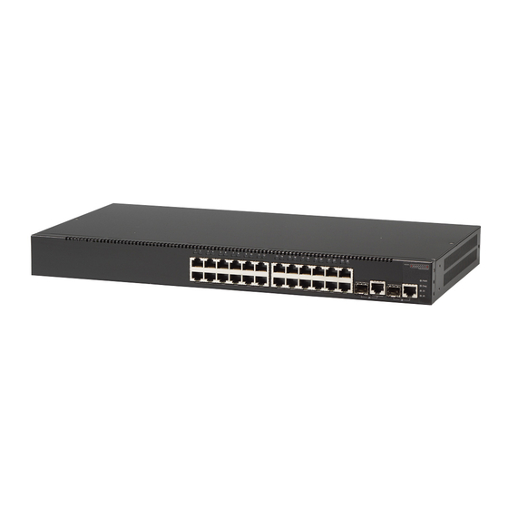
- Page 3 Installation Guide L2/4 Fast Ethernet Switch Layer 2 Standalone Switch with 24 100BASE-TX (RJ-45) Ports, and 2 Gigabit Combination Ports (RJ-45/SFP)
- Page 4 ES3526XA E112007-LP-R01 150000051300A...
- Page 5 Compliances and Safety Warnings FCC - Class A This equipment generates, uses, and can radiate radio frequency energy and, if not installed and used in accordance with the instruction manual, may cause interference to radio communications. It has been tested and found to comply with the limits for a Class A computing device pursuant to Subpart B of Part 15 of FCC Rules, which are designed to provide reasonable protection against such interference when operated in a commercial environment.
- Page 6 CE Mark Declaration of Conformance for EMI and Safety (EEC) This information technology equipment complies with the requirements of the Council Directive 89/336/EEC on the Approximation of the laws of the Member States relating to Electromagnetic Compatibility and 73/23/EEC for electrical equipment used within certain voltage limits and the Amendment Directive 93/68/EEC.
- Page 7 Safety Compliance Warning: Fiber Optic Port Safety When using a fiber optic port, never look at the transmit laser while it is powered on. Also, never look directly at the fiber TX port and fiber cable CLASS I LASER DEVICE ends when they are powered on.
- Page 8 Power Cord Set U.S.A. and Canada The cord set must be UL-approved and CSA certified. The minimum specifications for the flexible cord are: - No. 18 AWG - not longer than 2 meters, or 16 AWG. - Type SV or SJ - 3-conductor The cord set must have a rated current capacity of at least 10 A The attachment plug must be an earth-grounding type with NEMA...
- Page 9 France et Pérou uniquement: Ce groupe ne peut pas être alimenté par un dispositif à impédance à la terre. Si vos alimentations sont du type impédance à la terre, ce groupe doit être alimenté par une tension de 230 V (2 P+T) par le biais d’un transformateur d’isolement à rapport 1:1, avec un point secondaire de connexion portant l’appellation Neutre et avec raccordement direct à...
- Page 10 Stromkabel . Dies muss von dem Land, in dem es benutzt wird geprüft werden: Schweiz Dieser Stromstecker muss die SEV/ASE 1011 Bestimmungen ein- halten. Europa Das Netzkabel muss vom Typ HO3VVF3GO.75 (Mindestan- forderung) sein und die Aufschrift <HAR> oder <BASEC> tragen. Der Netzstecker muss die Norm CEE 7/7 erfüllen (”SCHUKO”).
- Page 11 Environmental Statement The manufacturer of this product endeavors to sustain an environmentally-friendly policy throughout the entire production process. This is achieved though the following means: • Adherence to national legislation and regulations on environmental production standards. • Conservation of operational resources. •...
- Page 12 viii...
- Page 13 About This Guide Purpose This guide details the hardware features of the switch, including the physical and performance-related characteristics, and how to install the switch. Audience The guide is intended for use by network administrators who are responsible for installing and setting up network equipment;...
-
Page 15: Table Of Contents
Contents Chapter 1: Introduction Overview Switch Architecture Network Management Options Description of Hardware 10BASE-T/100BASE-TX Ports 1000BASE-T/SFP Ports Port and System Status LEDs Power Supply Socket Features and Benefits Connectivity Expandability Performance Management Chapter 2: Network Planning Introduction to Switching Application Examples Collapsed Backbone Network Aggregation Plan Remote Connections with Fiber Cable... - Page 16 Contents Chapter 4: Making Network Connections Connecting Network Devices Twisted-Pair Devices Cabling Guidelines Connecting to PCs, Servers, Hubs and Switches Network Wiring Connections Fiber Optic SFP Devices Connectivity Rules 1000BASE-T Cable Requirements 1000 Mbps Gigabit Ethernet Collision Domain 100 Mbps Fast Ethernet Collision Domain 10 Mbps Ethernet Collision Domain Cable Labeling and Connection Records Appendix A: Troubleshooting...
- Page 17 Tables Table 1-1 Port Status LEDs Table 1-2 System Status LEDs Table 3-1 Serial Cable Wiring Table 4-1 Maximum 1000BASE-T Gigabit Ethernet Cable Length Table 4-2 Maximum 1000BASE-SX Gigabit Ethernet Cable Lengths Table 4-3 Maximum 1000BASE-LX Gigabit Ethernet Cable Length Table 4-4 Maximum 1000BASE-LH Gigabit Ethernet Cable Length Table 4-5...
- Page 18 Figures Figure 1-1 Front and Rear Panels Figure 1-2 Port LEDs Figure 1-3 System LEDs Figure 1-4 Power Supply Socket Figure 2-1 Collapsed Backbone Figure 2-2 Network Aggregation Plan Figure 2-3 Remote Connections with Fiber Cable Figure 2-4 Making VLAN Connections Figure 3-1 RJ-45 Connections Figure 3-2...
-
Page 19: Chapter 1: Introduction
SNMP-based management agent, which provides both in-band and out-of-band access for managing the switch. The ES3526XA provides a broad range of powerful features for Layer 2 switching, delivering reliability and consistent performance for your network traffic. It brings order to poorly performing networks by segregating them into separate broadcast domains with IEEE 802.1Q compliant VLANs, and empowers multimedia... -
Page 20: Switch Architecture
Network Management Options With a comprehensive array of LEDs, the ES3526XA provides “at a glance” monitoring of network and port status. The switch can be managed over the network with a web browser or Telnet application, or via a direct connection to the console port. -
Page 21: 1000Base-T/Sfp Ports
(See “1000BASE-T Pin Assignments” on page B-3.) Port and System Status LEDs The ES3526XA includes a display panel for key system and port indications that simplify installation and network troubleshooting. The LEDs, which are located on the front panel for easy viewing, are shown below and described in the following tables. -
Page 22: Power Supply Socket
Introduction System LEDs ES3526XA Diag Figure 1-3 System LEDs Table 1-2 System Status LEDs Condition Status On Green The unit’s internal power supply is operating normally. On Amber The unit’s internal power supply has failed. The unit has no power connected. -
Page 23: Features And Benefits
Features and Benefits Features and Benefits Connectivity • 24 dual-speed ports for easy Fast Ethernet integration and for protection of your investment in legacy LAN equipment. • Auto-negotiation enables each RJ-45 port to automatically select the optimum communication mode (half or full duplex) if this feature is supported by the attached device;... - Page 24 Introduction...
-
Page 25: Chapter 2: Network Planning
Chapter 2: Network Planning Introduction to Switching A network switch allows simultaneous transmission of multiple packets via non-crossbar switching. This means that it can partition a network more efficiently than bridges or routers. The switch has, therefore, been recognized as one of the most important building blocks for today’s networking technology. -
Page 26: Application Examples
Network Planning Application Examples The ES3526XA is not only designed to segment your network, but also to provide a wide range of options in setting up network connections. Some typical applications are described below. Collapsed Backbone The ES3526XA is an excellent choice for mixed Ethernet, Fast Ethernet, and Gigabit Ethernet installations where significant growth is expected in the near future. -
Page 27: Network Aggregation Plan
Application Examples Network Aggregation Plan With 26 parallel bridging ports (i.e., 26 distinct collision domains), the ES3526XA can collapse a complex network down into a single efficient bridged node, increasing overall bandwidth and throughput. In the figure below, the 10BASE-T/100BASE-TX ports on the switch are providing 100 Mbps connectivity for up to 24 segments. -
Page 28: Remote Connections With Fiber Cable
1000BASE-LX (SMF) link up to 5 km, and a 1000BASE-LH link up to 70 km. This allows a Gigabit Ethernet Switch to serve as a collapsed backbone, providing direct connectivity for a widespread LAN. The figure below illustrates this switch connecting multiple segments with fiber cable. Headquarters ES3526XA Slave Stack Master Uplink Uplink 27/Down 28/Up... -
Page 29: Making Vlan Connections
VLAN group to which it belongs. Untagged VLANs can be used for small networks attached to a single switch. However, tagged VLANs should be used for larger networks, and all the VLANs assigned to the inter-switch links. ES3526XA Slave Stack Master Uplink... -
Page 30: Application Notes
Network Planning Application Notes Full-duplex operation only applies to point-to-point access (such as when a switch is attached to a workstation, server or another switch). When the switch is connected to a hub, both devices must operate in half-duplex mode. Avoid using flow control on a port connected to a hub unless it is actually required to solve a problem. -
Page 31: Chapter 3: Installing The Switch
Chapter 3: Installing the Switch Selecting a Site Switch units can be mounted in a standard 19-inch equipment rack or on a flat surface. Be sure to follow the guidelines below when choosing a location. • The site should: - be at the center of all the devices you want to link and near a power outlet. - be able to maintain its temperature within 0 to 50 °C (32 to 122 °F) and its humidity within 10% to 90%, non-condensing - provide adequate space (approximately two inches) on all sides for proper air... -
Page 32: Equipment Checklist
Then, before beginning the installation, be sure you have all other necessary installation equipment. Package Contents • Fast Ethernet Switch (ES3526XA) • Four adhesive foot pads • Bracket Mounting Kit containing two brackets and eight screws for attaching the brackets to the switch •... -
Page 33: Mounting
Mounting Mounting This switch can be mounted in a standard 19-inch equipment rack or on a desktop or shelf. Mounting instructions for each type of site follow. Rack Mounting Before rack mounting the switch, pay particular attention to the following factors: •... -
Page 34: Desktop Or Shelf Mounting
Installing the Switch Mount the device in the rack, using four rack-mounting screws (not provided). Be sure to secure the lower rack-mounting screws first to prevent the brackets being bent by the weight of the switch. Figure 3-3 Installing the Switch in a Rack If installing a single switch only, turn to “Connecting to a Power Source”... - Page 35 Mounting Set the device on a flat surface near an AC power source, making sure there are at least two inches of space on all sides for proper air flow. If installing a single switch only, go to “Connecting to a Power Source” at the end of this chapter.
-
Page 36: Installing An Optional Sfp Transceiver
Installing the Switch Installing an Optional SFP Transceiver E S 3 5 2 6 X D i a Figure 3-5 Inserting an SFP Transceiver into a slot The SFP slots support the following optional SFP transceivers: • 1000BASE-SX • 1000BASE-LX •... -
Page 37: Connecting To A Power Source
Connecting to a Power Source Connecting to a Power Source To connect a switch to a power source: Insert the power cable plug directly into the AC socket located at the back of the switch. 100-240V ~50-60Hz 0.8A Figure 3-6 Power Socket Plug the other end of the cable into a grounded, 3-pin, AC power source. -
Page 38: Wiring Map For Serial Cable
Installing the Switch Wiring Map for Serial Cable Table 3-1 Serial Cable Wiring Switch’s 9-Pin Null Modem PC’s 9-Pin Serial Port DTE Port 2 RXD (receive data) <---------------------------- 3 TXD (transmit data) 3 TXD (transmit data) -----------------------------> 2 RXD (receive data) 5 SGND (signal ground) ------------------------------ 5 SGND (signal ground) No other pins are used. -
Page 39: Chapter 4: Making Network Connections
Chapter 4: Making Network Connections Connecting Network Devices The ES3526XA is designed to be connected to 10 or 100 Mbps network cards in PCs and servers, as well as to other switches and hubs. It may also be connected to remote devices using optional 1000BASE-SX, 1000BASE-LX, or 1000BASE-LH SFP transceivers. -
Page 40: Connecting To Pcs, Servers, Hubs And Switches
Making Network Connections Connecting to PCs, Servers, Hubs and Switches Attach one end of a twisted-pair cable segment to the device’s RJ-45 connector. Figure 4-1 Making Twisted-Pair Connections If the device is a network card and the switch is in the wiring closet, attach the other end of the cable segment to a modular wall outlet that is connected to the wiring closet. -
Page 41: Figure 4-2 Network Wiring Connections
Twisted-Pair Devices Label the cables to simplify future troubleshooting. See “Cable Labeling and Connection Records” on page 4-6. Equipment Rack Switch (side view) ES3526XA Diag Punch-Down Block Patch Panel Wall Figure 4-2 Network Wiring Connections... -
Page 42: Fiber Optic Sfp Devices
Making Network Connections Fiber Optic SFP Devices An optional Gigabit SFP transceiver (1000BASE-SX, 1000BASE-LX or 1000BASE-LH) can be used for a backbone connection between switches, or for connecting to a high-speed server. Each single-mode fiber port requires 9/125 micron single-mode fiber optic cable with an LC connector at both ends. -
Page 43: Connectivity Rules
Connectivity Rules The 1000BASE-SX, 1000BASE-LX, 1000BASE-LH fiber optic ports operate at 1 Gbps, full duplex, with auto-negotiation of flow control. The maximum length for fiber optic cable operating at Gigabit speed will depend on the fiber type as listed under “1000 Mbps Gigabit Ethernet Collision Domain” on page 4-5. Connectivity Rules When adding hubs (repeaters) to your network, please follow the connectivity rules listed in the manuals for these products. -
Page 44: 100 Mbps Fast Ethernet Collision Domain
Making Network Connections Table 4-4 Maximum 1000BASE-LH Gigabit Ethernet Cable Length Fiber Size Fiber Bandwidth Maximum Cable Length Connector 9/125 micron 2 m - 70 km single-mode fiber (7 ft - 43.5 miles) 100 Mbps Fast Ethernet Collision Domain Table 4-5 Maximum Fast Ethernet Cable Lengths Type Cable Type Max. -
Page 45: Appendix A: Troubleshooting
Appendix A: Troubleshooting Diagnosing Switch Indicators Table A-1 Troubleshooting Chart Symptom Action PWR LED is Off • Check connections between the switch, the power cord and the wall outlet. • Contact your dealer for assistance PWR LED is Amber • Internal power supply has failed. Contact your local dealer for assistance. -
Page 46: Installation
Troubleshooting Installation Verify that all system components have been properly installed. If one or more components appear to be malfunctioning (such as the power cord or network cabling), test them in an alternate environment where you are sure that all the other components are functioning properly. -
Page 47: Appendix B: Cables
Appendix B: Cables Twisted-Pair Cable and Pin Assignments For 10/100BASE-TX connections, the twisted-pair cable must have two pairs of wires. For 1000BASE-T connections the twisted-pair cable must have four pairs of wires. Each wire pair is identified by two different colors. For example, one wire might be green and the other, green with white stripes. -
Page 48: Straight-Through Wiring
Cables Table B-1 10/100BASE-TX MDI and MDI-X Port Pinouts MDI Signal Name MDI-X Signal Name Transmit Data plus (TD+) Receive Data plus (RD+) Transmit Data minus (TD-) Receive Data minus (RD-) Receive Data plus (RD+) Transmit Data plus (TD+) Receive Data minus (RD-) Transmit Data minus (TD-) Not used Not used... -
Page 49: 1000Base-T Pin Assignments
Twisted-Pair Cable and Pin Assignments You must connect all four wire pairs as shown in the following diagram to support Gigabit Ethernet. EIA/TIA 568B RJ-45 Wiring Standard 10/100BASE-TX Crossover Cable White/Orange Stripe Orange White/Green Stripe End A End B Blue White/Blue Stripe Green White/Brown Stripe... -
Page 50: Fiber Standards
Cables Cable Testing for Existing Category 5 Cable Installed Category 5 cabling must pass tests for Attenuation, Near-End Crosstalk (NEXT), and Far-End Crosstalk (FEXT). This cable testing information is specified in the ANSI/TIA/EIA-TSB-67 standard. Additionally, cables must also pass test parameters for Return Loss and Equal-Level Far-End Crosstalk (ELFEXT). -
Page 51: Appendix C: Specifications
Appendix C: Specifications Physical Characteristics Ports 24 10/100BASE-TX, with auto-negotiation 2 10/100/1000BASE-T shared with two SFP transceiver slots Network Interface Ports 1-24: RJ-45 connector, auto MDI/X 10BASE-T: RJ-45 (100-ohm, UTP cable; Category 3 or better) 100BASE-TX: RJ-45 (100-ohm, UTP cable; Category 5 or better) 1000BASE-T: RJ-45 (100-ohm, UTP or STP cable;... -
Page 52: Switch Features
Specifications AC Input 100 to 240 V, 50-60 Hz, 0.8A Power Supply Internal, auto-ranging transformer: 100 to 240 VAC, 50 to 60 Hz Power Consumption 25 Watts maximum Maximum Current 0.6 A @ 100 VAC 0.3 A @ 240 VAC Switch Features Forwarding Mode Store-and-forward... -
Page 53: Standards
Standards Standards Standards IEEE 802.3-2002 IEEE 802.3-2005 Ethernet, Fast Ethernet, Gigabit Ethernet Ethernet, Fast Ethernet, Gigabit Ethernet Full-duplex flow control Full-duplex flow control Link Aggregation Control Protocol Link Aggregation Control Protocol IEEE 802.1D Spanning Tree Protocol ISO/IEC 8802-3 IEEE 802.1w Rapid Spanning Tree Protocol ISO/IEC 8802-3 Compliances Compliances... - Page 54 Specifications...
- Page 55 Glossary 10BASE-T IEEE 802.3-2005 specification for 10 Mbps Ethernet over two pairs of Category 3, 4, or 5 UTP cable. 100BASE-FX IEEE 802.3-2005 specification for 100 Mbps Ethernet over two strands of 50/125, 62.5/125 micron, or 9/125 micron core fiber cable. 100BASE-TX IEEE 802.3-2005 specification for 100 Mbps Ethernet over two pairs of Category 5 UTP cable.
- Page 56 Glossary Collision A condition in which packets transmitted over the cable interfere with each other. Their interference makes both signals unintelligible. Collision Domain Single CSMA/CD LAN segment. CSMA/CD CSMA/CD (Carrier Sense Multiple Access/Collision Detect) is the communication method employed by Ethernet, Fast Ethernet, and Gigabit Ethernet. End Station A workstation, server, or other device that does not forward traffic.
- Page 57 Glossary IEEE 802.3u Defines CSMA/CD access method and physical layer specifications for 100BASE-TX Fast Ethernet. (Now incorporated in IEEE 802.3-2005.) IEEE 802.3x Defines Ethernet frame start/stop requests and timers used for flow control on full-duplex links. (Now incorporated in IEEE 802.3-2005.) IEEE 802.3z Defines CSMA/CD access method and physical layer specifications for 1000BASE Gigabit Ethernet.
- Page 58 Glossary RJ-45 Connector A connector for twisted-pair wiring. Switched Ports Ports that are on separate collision domains or LAN segments. Telecommunications Industry Association Transmission Control Protocol/Internet Protocol (TCP/IP) Protocol suite that includes TCP as the primary transport protocol, and IP as the network layer protocol.
- Page 59 Index 1000 Mbps 4-5 Numerics console port, pin assignments 3-7 10 Mbps connectivity rules 4-6 contents of package 3-2 100 Mbps connectivity rules 4-6 cooling problems A-1 1000 Mbps connectivity rules 4-5 cord sets, international 3-7 1000BASE-LH fiber cable Lengths 4-6 1000BASE-LX fiber cable Lengths 4-5 1000BASE-SX fiber cable Lengths 4-5 desktop mounting 3-4...
- Page 60 Index rear panel of switch 1-1 rear panel socket 1-4 laser safety 4-4 RJ-45 port 1-2, 1-3 LC port connections 4-4 connections 4-1 LED indicators pinouts B-3 Diag 1-4 RMON 1-2 Power 1-4 RS-232 port 1-2 problems A-1 rubber foot pads, attaching 3-4 location requirements 3-1 screws for rack mounting 3-2 management...
- Page 61 Index web-based management 1-2 Index-3...
- Page 62 Index Index-4...
- Page 64 ES3526XA E112007-LP-R01 150000051300A...
Need help?
Do you have a question about the ES3526XA and is the answer not in the manual?
Questions and answers