Table of Contents
Advertisement
Quick Links
Advertisement
Table of Contents
Troubleshooting

Subscribe to Our Youtube Channel
Related Manuals for Edge-Core ES4626


Summary of Contents for Edge-Core ES4626
- Page 1 ES4626/ES4650 L3 Gigabit Ethernet Switch www.edge-core.com...
- Page 2 Preface ES4626/ES4650 L3 Gigabit Ethernet Switch is a high performance routing switch released by Edge-Core that can be deployed as an aggregation device for campus networks, enterprise networks, as well as core layer switches for small and medium-sized networks.ES4626/ES4650 L3 Gigabit Ethernet Switch support a variety of network interfaces from 100Mb, 1000Mb to 10 GB Ethernet.
-
Page 3: Table Of Contents
Content CHAPTER 1 SWITCH MANAGEMENT................20 1.1 M ................... 20 ANAGEMENT PTIONS 1.1.1 Out-Of-Band Management................20 1.1.2 In-band Management ..................23 1.1.3 Management Via Telnet .................. 24 1.1.4 Management Via HTTP................... 26 1.2 M ..................29 ANAGEMENT NTERFACE 1.2.1 CLI Interface ....................29 1.2.2 Configuration Modes .................. - Page 4 2.4.2 SNMP Configuration Task List................. 74 2.4.3 Commands For SNMP ..................76 2.4.4 Typical SNMP Configuration Examples............86 2.4.5 SNMP Troubleshooting ................... 87 2.5 S ....................88 WITCH PGRADE 2.5.1 Switch System Files ..................88 2.5.2 BootROM Upgrade ..................88 2.5.3 FTP/TFTP Upgrade..................
- Page 5 2.10.7 Telnet server user configuration ..............131 2.10.8 Telnet security IP..................132 CHAPTER 3 PORT CONFIGURATION ................ 133 3.1 I ..................133 NTRODUCTION TO 3.2 P ................... 133 ONFIGURATION 3.2.1 Network Port Configuration ................133 3.2.2 VLAN Interface Configuration ............... 142 3.2.3 Network Management Port Configuration .............
- Page 6 4.6 W ....................167 ANAGEMENT 4.6.1 LACP port group configuration ..............167 4.6.2 LACP port configuration ................167 CHAPTER 5 VLAN CONFIGURATION ................ 169 5.1 VLAN C ..................169 ONFIGURATION 5.1.1 Introduction To VLAN ..................169 5.1.2 VLAN Configuration Task List ............... 170 5.1.3 Commands For Vlan Configuration...............
- Page 7 CHAPTER 6 MAC TABLE CONFIGURATION ............. 209 6.1 I MAC T ................209 NTRODUCTION TO ABLE 6.1.1 Obtaining MAC Table ..................209 6.1.2 Forward or Filter.....................211 6.2 M ........... 212 DDRESS ABLE ONFIGURATION 6.3 C .......... 212 OMMANDS FOR ADDRESS TABLE CONFIGURATION 6.3.1 mac-address-table aging-time...............
- Page 8 7.3.18 spanning-tree mst priority................237 7.3.19 spanning-tree portfast ................. 238 7.3.20 spanning-tree digest-snooping..............238 7.3.21 spanning-tree tcflush (global mode) ............239 7.3.22 spanning-tree tcflush (port mode) ............... 239 7.4 MSTP E ....................240 XAMPLE 7.5 MSTP T ..................245 ROUBLESHOOTING 7.5.1 Commands for Monitor And Debug...............
- Page 9 10.1.3 Commands for Layer 3 Interface..............286 10.2 IP C ....................286 ONFIGURATION 10.2.1 Introduction to IPv4, IPv6 ................286 10.2.2 IP Configuration ..................289 10.2.3 IP Configuration Examples................303 10.2.4 IP Troubleshooting ..................307 10.3 IP F ....................317 ORWARDING 10.3.1 Introduction to IP Forwarding ..............
- Page 10 12.1.2 option 82 Working Mechanism..............355 12.2 DHCP 82 C ............... 356 OPTION ONFIGURATION 12.2.1 DHCP option 82 Configuration Task List ............. 356 12.2.2 Command for DHCP option 82 ..............358 12.3 DHCP 82 A ............361 OPTION PPLICATION XAMPLES 12.4 DHCP 82 T ............
- Page 11 15.3.4 anti-arpscan trust ..................391 15.3.5 anti-arpscan trust ip..................391 15.3.6 anti-arpscan recovery enable..............392 15.3.7 anti-arpscan recovery time................392 15.3.8 anti-arpscan log enable................392 15.3.9 anti-arpscan trap enable ................393 15.3.10 show anti-arpscan ..................393 15.3.11 debug anti-arpscan..................395 15.4 ARP S ..........
- Page 12 17.3.1 Introduction to Static Route ................. 429 17.3.2 Introduction to Default Route ..............429 17.3.3 Static Route Configuration Task List............430 17.3.4 Commands for Static Route ................ 430 17.3.5 Configuration Examples ................434 17.4 RIP........................435 17.4.1 Introduction to RIP ..................435 17.4.2 RIP Configuration Task List.................
- Page 13 17.9.3 MBGP4+ Examples..................631 17.9.4 MBGP4+ Troubleshooting................633 CHAPTER 18 IGMP SNOOPING ................. 634 18.1 I IGMP S ..............634 NTRODUCTION TO NOOPING 18.2 IGMP S ............... 634 NOOPING ONFIGURATION 18.3 C IGMP S ............... 636 OMMANDS FOR NOOPING 18.3.1 ip igmp snooping..................636 18.3.2 ip igmp snooping vlan .................
- Page 14 20.2.3 Commands for PIM-DM ................657 20.2.4 PIM-DM Configuration Examples..............661 20.2.5 PIM-DM Troubleshooting ................662 20.3 PIM-SM......................668 20.3.1 Introduction to PIM-SM ................668 20.3.2 PIM-SM Configuration Task List..............669 20.3.3 Commands for PIM-SM................672 20.3.4 PIM-SM Configuration Examples ..............681 20.3.5 PIM-SM Troubleshooting................
- Page 15 21.2.4 PIM-SM Typical Application................. 757 21.2.5 PIM-SM Troubleshooting................759 21.3 MLD ........................769 21.3.1 Introduction to MLD..................769 21.3.2 MLD Configuration Task List ............... 769 21.3.3 Commands for MLD ..................771 21.3.4 MLD Typical Application ................777 21.3.5 MLD Troubleshooting .................. 777 21.4 MLD S ....................
- Page 16 23.1.3 The Encapsulation of EAPOL Messages ............ 821 23.1.4 The Encapsulation of EAP Attributes ............823 23.1.5 The Authentication Methods of 802.1x ............824 23.1.6 The Extension and Optimization of 802.1x..........829 23.1.7 The Features of VLAN Allocation ..............830 23.2 802.1 ...............
- Page 17 CHAPTER 24 THE NUMBER LIMITATION FUNCTION OF PORT, MAC IN VLAN AND IP CONFIGURATION....................863 24.1 I , MAC VLAN NTRODUCTION TO THE UMBER IMITATION UNCTION OF ..........................863 24.2 T , MAC VLAN IP C UMBER IMITATION UNCTION OF ONFIGURATION ......................
- Page 18 25.3.6 interface ...................... 883 25.3.7 preempt-mode..................... 883 25.3.8 priority ......................884 25.3.9 router vrrp ....................884 25.3.10 show vrrp ....................884 25.3.11 virtual-ip..................... 885 25.4 T VRRP S ................... 886 YPICAL CENARIO 25.5 VRRP T .................. 887 ROUBLESHOOTING 25.6 W .....................
- Page 19 26.4 MRPP ..................900 TYPICAL SCENARIO 26.5 MRPP .................. 902 TROUBLESHOOTING CHAPTER 27 CLUSTER CONFIGURATION ............... 904 27.1 I ..........904 NTRODUCTION TO CLUSTER NETWORK MANAGEMENT 27.2 C ......905 LUSTER ETWORK ANAGEMENT ONFIGURATION EQUENCE 27.3 C ..................907 OMMANDS FOR CLUSTER 27.3.1 cluster run ....................
-
Page 20: Chapter 1 Switch Management
Chapter 1 Switch Management 1.1 Management Options After purchasing the switch, the user needs to configure the switch for network management. ES4626/ES4650 Switch provides two management options: in-band management and out-of-band management. 1.1.1 Out-Of-Band Management Out-of-band management is the management through Console interface. Generally, the user will use out-of-band management for the initial switch configuration, or when in-band management is not available. - Page 21 Windows 9x/NT/2000/XP. Serial port cable One end attach to the RS-232 serial port, the other end to the Console port. ES4626/ES4650 Functional Console port required. Step 2 Entering the HyperTerminal Open the HyperTerminal included in Windows after the connection established. The example below is based on the HyperTerminal included in Windows XP.
- Page 22 3) In the “Connecting using” drop-list, select the RS-232 serial port used by the PC, e.g. COM1, and click “OK”. Fig 1-4 Opening HyperTerminal 4) COM1 property appears, select “9600” for “Baud rate”, “8” for “Data bits”, “none” for “Parity checksum”, “1” for stop bit and “none” for traffic control; or, you can also click “Restore default”...
-
Page 23: In-Band Management
Power on the switch, the following appears in the HyperTerminal windows, that is the CLI configuration mode for ES4626/ES4650 Switch. ES4650 Management Switch Copyright (c) 2001-2004 by Accton Technology Corporation. All rights reserved. Reset chassis ... done. Testing RAM... 134,217,728 RAM OK. -
Page 24: Management Via Telnet
3) If not 2), Telnet client can connect to an IP address of the switch via other devices, such as a router. ES4626/ES4650 Switch is a Layer 3 switch that can be configured with several IP addresses. The following example assumes the shipment status of the switch where only VLAN1 exists in the system. - Page 25 Switch>en Switch#config Switch(Config)#interface vlan 1 Switch(Config-If-Vlan1)#ip address 10.1.128.251 255.255.255.0 Switch(Config-If-Vlan1)#no shutdown Step 2: Run Telnet Client program. Run Telnet client program included in Windows with the specified Telnet target. Fig 1-7Run telnet client program included in Windows Step 3: Login to the switch Login to the Telnet configuration interface.Valid login name and password are required, otherwise the switch will reject Telnet access.
-
Page 26: Management Via Http
Fig 1-8 Telnet Configuration Interface 1.1.4 Management Via HTTP To manage the switch via HTTP, the following conditions should be met: 1) Switch has an IP address configured 2) The host IP address (HTTP client) and the switch’s VLAN interface IP address are in the same network segment;... - Page 27 Switch(Config)#ip http server Step 2: Run HTTP protocol on the host. Open the Web browser on the host and type the IP address of the switch. Or run directly the HTTP protocol on the Windows. For example, the IP address of the switch is “10.1.128.251”.
- Page 28 Fig 1-10 Web Login Interface Input the right username and password, and then the main Web configuration interface is shown as below. Fig 1-11 Main Web Configuration Interface...
-
Page 29: Management Interface
1.2 Management Interface 1.2.1 CLI Interface CLI interface is familiar to most users. As before mentioned, out-of-band management and Telnet login are all performed through CLI interface to manage the switch. CLI Interface is supported by Shell program, which consists of a set of configuration commands. - Page 30 Or, when exit command is run under Global Mode, it will also return to the Admin Mode. ES4626/ES4650 Switch also provides a shortcut key sequence "Ctrl+z”, this allows an easy way to exit to Admin Mode from any configuration mode (except User Mode).
- Page 31 Interface anx)# switch IPs, etc command to vlan <Vlan-id> command under return to Global Mode. Global Mode. Ethernet Port Type Configure Use the exit interface Switch(Config- supported command to ethernet ethernetxx)# duplex mode, return <interface-list> command under speed, etc. Global Mode. Global Mode.
-
Page 32: Configuration Syntax
Mode 1.2.3 Configuration Syntax ES4626/ES4650 Switch provides various configuration commands. Although all the commands are different, they all abide by the syntax for ES4626/ES4650 Switch configuration commands. The general commands format of ES4626/ES4650 Switch is shown below: cmdtxt <variable> { enum1 | … | enumN } [option] Conventions: cmdtxt in bold font indicates a command keyword;... -
Page 33: Shortcut Key Support
<string> rw 1.2.4 Shortcut Key Support ES4626/ES4650 Switch provides several shortcut keys to facilitate user configuration, such as up, down, left, right and Blank Space. If the terminal does not recognize Up and Down keys, ctrl +p and ctrl +n can be used instead. -
Page 34: Input Verification
There are two ways in ES4626/ES4650 Switch for the user to access help information: the “help” command and the “?”. Access to Help Usage and function Help Under any command line prompt, type in “help” and press Enter will get a brief description of the associated help system. -
Page 35: Web Management
ES4626/ES4650 switch shell support fuzzy match in searching command and keyword. Shell will recognize commands or keywords correctly if the entered string causes no conflict. For example: 1. For command “show interfaces status ethernet 1/1”, typing “sh in status e 1/1” will work 2. - Page 36 Fig 1-13 Module Front Panel...
-
Page 37: Chapter 2 Basic Switch Configuration
Chapter 2 Basic Switch Configuration 2.1 Basic Switch Configuration Commands Basic switch configuration includes commands for entering and exiting the admin mode, commands for entering and exiting interface mode, for configuring and displaying the switch clock, for displaying the version information of the switch system, etc. Command Explanation Normal User Mode/ Admin Mode... - Page 38 Command: authentication login {local | radius | local radius | radius local|tacacs } no authentication login Function: Configure the authentication mode and priority on Telnet Server for remote login users; the “no authentication login” command restores to the default login authentication mode.
- Page 39 2.1.1.4 debug ssh-server Command: debug ssh-server no debug ssh-server Function: Display SSH server debugging information; the “no debug ssh-server” command stops displaying SSH server debugging information. Default: This function is disabled by default. Command mode: Admin Mode Example: Switch#debug ssh-server 2.1.1.5 dir Command: dir Function: Display the files and their sizes in the Flash memory.
- Page 40 no enable password Function: Configure the password used for enter Admin Mode from the User Mode, The “no enable password” command deletes this password Parameter: password is the configured code. Encryption will be performed by entering 8. Command mode: Global Mode Default: This password is empty by system default Usage Guide: Configure this password to prevent unauthorized entering Admin Mode.
- Page 41 Parameter <hostname> is the string for the prompt, up to 30 characters are allowed. Command mode: Global Mode Default: The default prompt is ES4626/ES4650 switch. Usage Guide: With this command, the user can set the CLI prompt of the switch according to their own requirements.
- Page 42 Switch(Config)#ip host beijing 200.121.1.1 2.1.1.13 ipv6 host Command: ipv6 host <hostname> <ipv6_addr> no ipv6 host <hostname> Function: Configure the mapping relationship between the IPv6 address and the host; the “no ipv6 host <hostname>” command deletes this mapping relationship name host,containing Parameter :...
- Page 43 Command mode: Admin Mode Default: The default setting is English display. Usage Guide: ES4626/ES4650 switch provides help information in two languages, the user can select the language according to their preference. After the system restart, the help information display will revert to English.
- Page 44 Usage guide: When both this password and login command are configured, users have to enter the password set by password command to enter normal user mode on console Example: Switch(Config)#password 8 test Switch(Config)#login 2.1.1.19 ping Command: ping [<ip-addr> | <host>|vrf|] Function: The switch send ICMP packet to remote devices to verify the connectivity between the switch and remote devices.
- Page 45 Displayed information Explanation VRF name: VPN Routing/Forwarding instance Target IP address: Target IP address Repeat count [5] Packet number, the default is 5 Datagram size in byte [56] ICMP packet size the default is 56 bytes Timeout in milli-seconds [2000]: Timeout (in milliseconds,) the default is 2 seconds.
- Page 46 switch>ping6 Target IPv6 address:fe80::2d0:59ff:feb8:3b27 Output Interface: vlan1 Use source address option[n]:y Source IPv6 address: fe80::203:fff:fe0b:16e3 Repeat count [5]: Datagram size in byte [56]: Timeout in milli-seconds [2000]: Extended commands [n]: Type ^c to abort. Sending 5 56-byte ICMP Echoes to fe80::2d0:59ff:feb8:3b27, using src address fe80::203:fff:fe0b:16e3, timeout is 2 seconds.
- Page 47 Command: reload Function: Warm reset the switch. Command mode: Admin Mode Usage Guide: The user can use this command to restart the switch without power off. 2.1.1.22 service password-encryption Command: service password-encryption no service password-encryption Function: Encrypt system password. The “no service password-encryption” command cancels the encryption Command mode: Global mode Default: no service password-encryption by system default...
- Page 48 2.1.1.25 setup Command: setup Function: Enter the Setup Mode of the switch. Command mode: Admin Mode Usage Guide: ES4626/ES4650 switch provides a Setup Mode, in which the user can configure IP addresses, etc. 2.1.1.26 terminal length Command: terminal length <0-512>...
- Page 49 Command mode: Admin mode Usage guide: Configures whether the current debugging messages is displayed on this terminal. If this command is configured on telnet or ssh clients, debug messages will be sent to that client. The debug message is displayed on console by default Example: Switch#terminal monitor 2.1.1.28 traceroute Command: traceroute {<ip-addr>...
- Page 50 user can not access in admin mode, other than common user mode. Notice: The user can log in use name and priority after the command configures, before login local command is executed (Enable username and password), it insures that priority of one user is maximum 15, so that users could log in by this username and access in admin mode and global mode to modify system configuration, otherwise, users only access in common mode, not admin mode to take the users effect.
-
Page 51: Monitor And Debug Command
ES4626/ES4650 switch provides various debug commands including ping, telnet, show and debug, etc. to help the users to check system configuration, operating status and locate problem causes. - Page 52 Telnet employs the Client-Server mode, the local system is the Telnet client and the remote host is the Telnet server. ES4626/ES4650 switch can be either the Telnet Server or the Telnet client.
- Page 53 Command Explanation Admin Mode Login to a remote host with the telnet [<ip-addr>] [<port>] Telnet client included in the switch. 2.2.3.3 Commands for Telnet 2.2.3.3.1 telnet Command: telnet {<ip-addr> | <ipv6-addr> | host <hostname>} [<port>] Function: Log on the remote host by Telnet Parameter:<ip-addr>...
-
Page 54: Ssh
Default: Telnet server function is enabled by default. Command mode: Global Mode Usage Guide: This command is available in Console only. The administrator can use this command to enable or disable the Telnet client to login to the switch. Example: Disable the Telnet server function in the switch. Switch(Config)#no ip telnet server 2.2.3.3.3 telnet-server securityip Command: telnet-server securityip <ip-addr>... - Page 55 SSH Server Configuration Command Explanation Global Mode Enable SSH function on the switch; the ssh-server enable “no command ssh-server enable” no ssh-server enable disables SSH function. Configure the username and password of SSH client software for logging on the ssh-user <user-name> password {0|7} switch;...
- Page 56 Default: The number of times for retrying SSH authentication is 3 by default. Example: Set the number of times for retrying SSH authentication to 5. Switch(Config)#ssh-server authentication-retries 5 2.2.4.3.2 ssh-server enable Command: ssh-server enable no ssh-server enable Function: Enable SSH function on the switch; the “no ssh-server enable” command disables SSH function.
-
Page 57: Traceroute
Default: SSH authentication timeout is 180 seconds by default. Example: Set SSH authentication timeout to 240 seconds. Switch(Config)#ssh-server timeout 240 2.2.4.3.5 ssh-user Command: ssh-user <username> password {0|7} <password> no ssh-user <username> Function: Configure the username and password of SSH client software for logging on the switch;... -
Page 58: Traceroute6
Trace route command is for testing the gateways through which the data packets travels from the source device to the destination device, so to check the network accessibility and locate the network failure. Execution procedure of the Trace route command consists of: first a data packet with TTL at 1 is sent to the destination address, if the first hop returns an ICMP error message to inform this packet can not be sent (due to TTL timeout), a data packet with TTL at 2 will be sent. - Page 59 Display the files and the sizes saved in the flash Display recent user input history show history command Display content in specified memory area show memory Display the switch parameter configuration show running-config validating at current operation state. Display the switch parameter configuration written in the Flash Memory at current operation state,...
- Page 60 the system clock can be adjusted in time if inaccuracy occurs. Example: Switch#show calendar Current time is TUE AUG 22 11: 00: 01 2002 2.2.7.1.2 show debugging Command: show debugging Function: Display the debug switch status. Usage Guide: If the user need to check what debug switches have been enabled, show debugging command can be executed.
- Page 61 address, Hex view of the information and character view. Example: Switch#show memory start address : 0x2100 number of words[64]: 002100: 0000 0000 0000 0000 0000 0000 0000 0000 *....* 002110: 0000 0000 0000 0000 0000 0000 0000 0000 *....* 002120: 0000 0000 0000 0000 0000 0000 0000 0000 *....* 002130: 0000 0000 0000 0000 0000 0000 0000 0000 *....*...
- Page 62 Example: Switch#show ssh-user test 2.2.7.1.8 show startup-config Command: show startup-config Function: Display the switch parameter configurations written into the Flash memory at the current operation; those are usually also the configuration files used for the next power-up. Default: If the configuration parameters read from the Flash are the same as the default operating parameter, nothing will be displayed.
- Page 63 Port VID :1 Current VLAN number the interface belongs Trunk allowed Vlan :ALL VLAN permitted by Trunk. 2.2.7.1.10 show users Command: show users Function: Display all user information that can login the switch . Usage Guide: This command can be used to check for all user information that can login the switch.
-
Page 64: Debug
Uptime is 0 weeks, 0 days, 0 hours, 28 minutes 2.2.8 Debug All the protocols ES4626/ES4650 switch supports have their corresponding debug commands. The users can use the information from debug commands for troubleshooting. Debug commands for their corresponding protocols will be introduced in the later chapters. - Page 65 provide a powerful support to the network administrator and developer in monitoring the network operation state and locating the network failures. The switch system log has following characteristics Log output from four directions (or log channels) of the Console, Telnet terminal and monitor, log buffer zone, and log host.
- Page 66 record and analyze the log by the syslog (system log protect session) on the UNIX/LINUX, as well as syslog similar applications on PC. The log information is classified into eight classes by severity or emergency procedure. One level per value and the higher the emergency level the log information has, the smaller its value will be.
- Page 67 SDRAM and the NVRAM (if exists) besides sent to all terminals. To check the log save in SDRAM and the NVRAM, we can use the show logging buffered command. To clear the log save in NVRAM and SDRAM log buffer zone, we can use the clear logging command 2.2.9.2 System Log Configuration 2.2.9.2.1 System Log Configuration Task Sequence 1.
- Page 68 2.2.9.2.2.2 clear logging Command: clear logging { sdram | nvram } Function: This command is used to clear all the information in the log buffer zone. Command Mode:Admin Mode Usage Guide: When the old information in the log buffer zone is no longer concerned, we can use this command to clear all the information example:Clear all information in the log buffer zone sdram Switch# clear logging sdram...
-
Page 69: Configurate Switch Ip Addresses
Switch(Config)#logging 3ffe:506::4 facility local7 level warnings 2.3 Configurate Switch IP Addresses All Ethernet ports of ES4626/ES4650 switch is default to Data Link layer ports and perform layer 2 forwarding. VLAN interface represent a Layer 3 interface function which can be assigned an IP address, which is also the IP address of the switch. All VLAN interface related configuration commands can be configured under VLAN Mode. -
Page 70: Commands For Configuring Switch Ip
1. Manual configuration 2. BootP configuration 3. DHCP configuration 1. Manual configuration Command Explanation Configure the VLAN interface IP address; address <ip_address> <mask> the “no ip address <ip_address> <mask> [secondary] [secondary]” command deletes VLAN no ip address <ip_address> <mask> interface IP address. [secondary] 2. - Page 71 Usage Guide: A VLAN interface must be created first before the user can assign an IP address to the switch. Example: Set 10.1.128.1/24 as the IP address of VLAN1 interface. Switch(Config)#interface vlan 1 Switch(Config-If-Vlan1)#ip address 10.1.128.1 255.255.255.0 Switch(Config-If-Vlan1)#exit 2.3.2.2 ip address bootp-client Command: ip address bootp-client no address ip bootp-client Function: Enable the switch to be a BootP client and obtain IP address and gateway...
-
Page 72: Snmp Configuration
Switch (Config-If-Vlan1)#ip address dhcp-client Switch (Config-If-Vlan1)#exit 2.4 SNMP Configuration 2.4.1 Introduction To SNMP SNMP (Simple Network Management Protocol) is a standard network management protocol widely used in computer network management. SNMP is an evolving protocol. SNMP v1 [RFC1157] is the first version of SNMP which is adapted by vast numbers of manufacturers for its simplicity and easy implementation;... - Page 73 Trap messages to NMS to inform the abnormal events. Besides, NMS can also be set to alert to some abnormal events by enabling RMON function. When alert events are triggered, Agents will send Trap messages or log the event according to the settings. Inform-Request is mainly used for inter-NMS communication in the layered network management.
-
Page 74: Snmp Configuration Task List
If the variable information of Agent MIB needs to be browsed, the MIB browse software needs to be run on the NMS. MIB in the Agent usually consists of public MIB and private MIB. The public MIB contains public network management information that can be accessed by all NMS;... - Page 75 6. Configure group 7. Configure view 8. Configuring TRAP 9. Enable/Disable RMON 1. Enable or disable SNMP Agent server function Command Explanation Enable the SNMP Agent function on the snmp-server switch; the “no snmp-server” command no snmp-server disables the SNMP Agent function on the switch.
-
Page 76: Commands For Snmp
6. Configure group Command Explanation Set the group information on the switch. snmp-server group <group-string> This command is used to configure VACM {NoauthNopriv|AuthNopriv|AuthPriv} for SNMP v3. [[read <read-string>] [write <write-string>] [notify <notify-string>]] no snmp-server group <group-string> {NoauthNopriv|AuthNopriv|AuthPriv} 7. Configure view Command Explanation Configure... - Page 77 Function: Enable RMON; the “no rmon enable” command disables RMON. Command mode: Global Mode Default: RMON is disabled by default. Example 1: Enable RMON Switch(config)#rmon enable Example 2: Disable RMON Switch(config)#no rmon enable 2.4.3.2 show snmp Command: show snmp Function: Display all SNMP counter information. Command mode: Admin Mode Example: Switch#show snmp...
- Page 78 supplied name error packets. encoding errors Number of encoding error packets. number of requested variables Number of variables requested by NMS. number of altered variables Number of variables set by NMS. get-request PDUs Number of packets received by “get” requests. get-next PDUs Number of packets received by “getnext”...
- Page 79 Community access Community access permission Trap-rec-address IP address which is used to receive Trap. Trap enable Enable or disable to send Trap. SecurityIP IP address of the NMS which is allowed to access Agent 2.4.3.4 snmp-server community Command: snmp-server community <string> {ro|rw} snmp-server community <string>...
- Page 80 Command: snmp-server enable traps no snmp-server enable traps Function: Enable the switch to send Trap message; the “no snmp-server enable traps” command disables the switch to send Trap message. Command mode: Global Mode Default: Trap message is disabled by default. Usage Guide: When Trap message is enabled, if Down/Up in device ports or of system occurs, the device will send Trap messages to NMS that receives Trap messages.
- Page 81 Configure an IP address to receive Trap Switch(config)#snmp-server host 1.1.1.5 v1 usertrap Delete a Trap receiving IP address Switch(config)#no snmp-server host 1.1.1.5 v1 usertrap Configure a Trap receiving IPv6 address Switch(config)#snmp-server host 2001:1:2:3::1 v1 usertrap Delete a Trap receiving IPv6 address Switch(config)#no snmp-server host 2001:1:2:3::1 v1 usertrap 2.4.3.8 debug snmp mib Command: debug snmp mib...
- Page 82 Displayed Information Explanation SNMP engineID Engine number Engine Boots Engine boot counts 2.4.3.11 show snmp group Command: show snmp group Function: Display the group information commands Command Mode: Admin Mode Example: Switch#show snmp group Group Name:initial Security Level:noAuthnoPriv Read View:one Write View:<no writeview specified>...
- Page 83 Displayed Information Explanation User name User name Engine ID Engine ID Priv Protocol Employed encryption algorithm Auth Protocol Employed identification algorithm Row status User state 2.4.3.14 show snmp view Command: show snmp view Function:Display the view information commands. Command Mode: Admin Mode Example: Switch#show snmp view View Name:readview...
- Page 84 Switch(config)#no snmp-server engineid A66688999F 2.4.3.16 snmp-server group Command: snmp-server group <group-string> {NoauthNopriv|AuthNopriv|AuthPriv} [[read <read-string>] [write <write-string>] [notify <notify-string>]] no snmp-server group <group-string> {NoauthNopriv|AuthNopriv|AuthPriv} Function:This command is used to configure a new group; the “no” form of this command deletes this group. Command Mode: Global Mode Parameter:<group-string >...
- Page 85 no snmp-server view <view-string> Function: This command is used to create or renew the view information; the “no" form of this command deletes the view information Command Mode:Global Mode Parameter: <view-string> view name, containing 1-32 characters; <oid-string>is OID number or corresponding node name, containing 1-255 characters. include|exclude , include/exclude this OID Usage Guide: The command supports not only the input using the character string of the variable OID as parameter.
-
Page 86: Typical Snmp Configuration Examples
deletes an User Switch (Config)#no snmp-server user tester UserGroup 2.4.3.20 snmp-server securityip Command:snmp-server securityip {<ipv4-address>| <ipv6-address>} no snmp-server securityip {<ipv4-address>| <ipv6-address>} Function: Configure to permit to access security IPv4 or IPv6 address of the switch NMS administration station; the“no snmp-server securityip {<ipv4-address>| <ipv6-address>}”command deletes configured security IPv4 or IPv6 address. -
Page 87: Snmp Troubleshooting
The IP address of the NMS is 1.1.1.5; the IP address of the switch (Agent) is 1.1.1.9 Scenario 1: The NMS network administrative software uses SNMP protocol to obtain data from the switch. The configuration on the switch is listed below: Switch(config)#snmp-server Switch(Config)#snmp-server community private rw Switch(Config)#snmp-server community public ro... -
Page 88: Switch Upgrade
If users still can’t solve the SNMP problems, Please contact our technical and service center. 2.5 Switch Upgrade ES4626/ES4650 switch provides two ways for switch upgrade: BootROM upgrade and the TFTP/FTP upgrade under Shell. 2.5.1 Switch System Files The system files includes system image file and boot file. The updating of the switch is to update the two files by overwrite the old files with the new ones. - Page 89 There are two methods for BootROM upgrade: TFTP and FTP, which can be selected at BootROM command settings. Console cable cable connection connection Fig 2-3 Typical topology for switch upgrade in BootROM mode The upgrade procedures are listed below: Step 1: As shown in the figure, a PC is used as the console for the switch.
- Page 90 Under BootROM mode, run “setconfig” to set the IP address and mask of the switch under BootROM mode, server IP address and mask, and select TFTP or FTP upgrade. Suppose the switch address is 192.168.1.2/24, and PC address is 192.168.1.66/24, and select TFTP upgrade, the configuration should like: [Boot]: setconfig Host IP Address: 10.1.1.1 192.168.1.2...
-
Page 91: Ftp/Tftp Upgrade
startup-config 2,922 1980-01-01 00: 09: 14 ---- temp.image 2,431,631 1980-01-01 00: 00: 32 ---- CONFIG RUN command Used to set the IMAGE file to run upon system start-up, and the configuration file to run upon configuration recovery. [Boot]: config run Boot File: [nos.img] nos1.image Config File: [boot.conf] 2.5.3 FTP/TFTP Upgrade... - Page 92 Boot file: refers to the file initializes the switch, also referred to as the ROM upgrade file (Large size file can be compressed as IMAGE file). In ES4626/ES4650 switch, the boot file is allowed to save in ROM only. ES4626/ES4650 switch mandates the name of the boot file to be boot.rom.
- Page 93 In ES4626/ES4650 switch, the running configuration file stores in the RAM. In the current version, the running configuration sequence running-config can be saved from the RAM to FLASH by write command or copy running-config startup-config command, so that the running configuration sequence becomes the start up configuration file, which is called configuration save.
- Page 94 Global Mode For FTP client, server file list can be checked. dir <ftpServerUrl> FtpServerUrl format looks like: ftp: //user: password@IP Address 2. FTP server configuration (1)Start FTP server Command Explanation Global Mode Start FTP server, the “no ftp-server enable” ftp-server enable command shuts down FTP server and no ftp-server enable prevents FTP user from logging in.
- Page 95 2.5.3.2.2 Commands for Switch Upgrade 2.5.3.2.2.1 copy(FTP) Command: copy <source-url> <destination-url> [ascii | binary] Function: Download files to the FTP client. Parameter : <source-url> is the location of the source files or directories to be copied;<destination-url> is the destination address to which the files or directories to be copied;forms of <source-url>...
- Page 96 (3)Save the running configuration files Switch#copy running-config startup-config 2.5.3.2.2.2 copy(TFTP) Command: copy <source-url> <destination-url> [ascii | binary] Function: Download files to the TFTP client Parameter:<source-url> is the location of the source files or directories to be cop ied;<destination-url> is the destination address to which the files or directories to be copied;forms of <source-url>...
- Page 97 2.5.3.2.2.3 dir Command: dir <ftp-server-url> Function: Browse the file list on the FTP server. Parameter:The form of < ftp-server-url > is:ftp://<username>:<password>@{<ipv 4address>|<ipv6address>},amongst <username> is the FTP user name,<password> i s the FTP user password, {<ipv4address>|<ipv6address>} is the IPv4 or IPv6 address of the FTP server. Command Mode: Global Mode Example: Browse the list of the files on the server with the FTP client Switch(Config)# dir ftp://user:password@IPv6 Address.
- Page 98 2.5.3.2.2.6 show ftp Command: show ftp Function: display the parameter settings for the FTP server Command mode: Admin Mode Default: No display by default. Example: Switch#show ftp Timeout : 600 Displayed information Description Timeout Timeout time. 2.5.3.2.2.7 show tftp Command: show tftp Function: display the parameter settings for the TFTP server Default: No display by default.
-
Page 99: Ftp/Tftp Configuration Examples
2.5.3.2.2.9 tftp-server retransmission-number Command: tftp-server retransmission-number <number> Function: Set the retransmission time for TFTP server Parameter: < number> is the time to re-transfer, the valid range is 1 to 20. Default: The default value is 5 retransmission. Command mode: Global Mode Example: Modify the retransmission to 10 times. - Page 100 FTP Configuration Computer side configuration: Start the FTP server software on the computer and set the username “Switch”, and the password “switch”. Place the “12_30_nos.img” file to the appropriate FTP server directory on the computer. The configuration procedures of the switch is listed below: Switch(Config)#inter vlan 1 Switch (Config-If-Vlan1)#ip address 10.1.1.2 255.255.255.0 Switch (Config-If-Vlan1)#no shut...
- Page 101 “nos.img” file from the switch to the computer. Scenario 3: The switch is used as TFTP server. The switch operates as the TFTP server and connects from one of its ports to a computer, which is a TFTP client. Transfer the “nos.img”...
- Page 102 Switch#copy tftp: //10.1.1.1/ boot.rom boot.rom Switch#copy tftp: //10.1.1.1/ startup-config startup-config Scenario 5: ES4626/ES4650 switch acts as FTP client to view file list on the FTP server. Synchronization conditions: The switch connects to a computer by an Ethernet port, the computer is a FTP server with an IP address of 10.1.1.1; the switch acts as a FTP client, and the IP address of the switch management VLAN1 interface is 10.1.1.2.
-
Page 103: Ftp/Tftp Troubleshooting
snmp.TXT 226 Transfer complete. Switch (Config)# 2.5.5 FTP/TFTP Troubleshooting 2.5.5.1 FTP Troubleshooting When upload/download system file with FTP protocol, the connectivity of the link must be ensured, i.e., use the “Ping” command to verify the connectivity between the FTP client and server before running the FTP program. If ping fails, you will need to check for appropriate troubleshooting information to recover the link connectivity. -
Page 104: Security Feature Configuration
start. If the system file and system start up file upgrade through FTP fails, please try to upgrade again or use the BootROM mode to upgrade. 2.5.5.2 TFTP Troubleshooting When upload/download system file with TFTP protocol, the connectivity of the link must be ensured, i.e., use the “Ping”... -
Page 105: Security Feature Configuration
processing the attacker’s data packet, leading to the denial of the service and worse can lead to leak of sensitive data of the server. Security feature refers to applications such as protocol check which is for protecting the server from attacks such as DoS. The protocol check allows the user to drop matched packets based on specified conditions. - Page 106 dosattack-check Enable the prevent-port-cheat function srcport-equal-dstport enable 2.6.2.4 Prevent TCP Fragment Attack Function Configuration Task Sequence 1.Enable the prevent TCP fragment attack function 2.Configure the minimum permitted TCP head length of the packet Command Explanation Global Mode Enable the prevent TCP fragment attack dosattack-check tcp-fragment enable function dosattack-check tcp-fragment enable...
-
Page 107: Security Feature Commands
2.6.3 Security Feature Commands 2.6.3.1 dosattack-check srcip-equal-dstip enable Command: [no] dosattack-check srcip-equal-dstip enable Function: Enable the function by which the switch checks if the source IP address is equal to the destination IP address; the “no” form of this command disables this function. Parameter: None Default: Disable the function by which the switch checks if the source IP address is equal to the destination IP address. - Page 108 Command Mode:Global Mode Usage Guide:With this function enabled, the switch will be able to drop follow four data packets containing unauthorized TCP label: SYN=1 while source port is smaller than 1024;TCP label positions are all 0 while its serial No. =0;FIN=1,URG=1,PSH=1 and the TCP serial No.=0;SYN=1 and FIN=1.
- Page 109 2.6.3.6 dosattack-check tcp-header Command: dosattack-check tcp-header <size> Function:Configure the minimum TCP head length permitted by the switch Parameter: <size> is the minimum TCP head length permitted by the switch Default:The length is 20 by default which is the shortest TCP head Command Mode:Global Mode Usage Guide:To use this function the “dosattack-check tcp-fragment enable”...
-
Page 110: Security Feature Example
Switch(Config)# dosattack-check icmp-attacking enable Switch(Config)# dosattack-check icmpv4-size 100 2.6.3.9 dosattack-check icmpv6-size Command:dosattack-check icmpv6-size <size> Function:Configure the max net length of the ICMPv6 data packet permitted by the switch Parameter:<size> is the max net length of the ICMPv6 data packet permitted by the switch Default:The value is 0x200 by default Command Mode:Global Mode... -
Page 111: Jumbo Configuration Task Sequence
So far the Jumbo (Jumbo Frame) has not reach a determined standard in the industry (including the format and length of the frame). Normally frames sized within 1519-8996 should be considered Jumbo frame. Networks with Jumbo frames will increase the speed of the whole network by 2% to 5%. Technically the Jumbo is just a lengthened frame sent and received by the switch. -
Page 112: Sflow Configuration Task
monitoring the network traffic information developed by the InMon Company.The monitored switch or router sends date to the client analyzer through its main operations such as sampling and statistic, then the analyzer will analyze acconrding to the user requirements so to monitor the network. A sFlow monitor system includes: sFlow proxy, central data collector and sFlow analyzer. -
Page 113: Commands For Sflow
Configure the source IP address applied by sflow agent-address the sFlow proxy; the “no” form of the <collector-address> command deletes this address. no sflow agent-address 3. Configure the sFlow proxy priority Command Explanation Global Mode Configure the priority when sFlow receives sflow priority <priority-vlaue>... - Page 114 2.8.3.1 sflow destination Command: sflow destination <collector-address> [<collector-port>] no sflow destination Function:Configure the IP address and port number of the host on which the sFlow analysis software is installed. If the port has been configured with IP address, the port configuration will be applied, or else the global configuration will be applied.
- Page 115 Function: Configure the priority when sFlow receives packet from the hardware. The "no” form of the command restores to the default Parameter: <priority-value> is the priority value with a valid range of 0-3. Command Mode: Global mode Default: The default value is 0 Usage Guide:When sample packet is sent to the CPU, it is recommended not to assign high priority for the packet so that regular receiving and sending of other protocol packet will not be interfered.
- Page 116 Example: Configure the max length of the sFlow packet data to 1000 switch #Config-If-Ethernet3/2)#sflow data-len 1000 2.8.3.6 sflow counter-interval Command: sflow counter-interval <interval-value> no sflow counter-interval Function: Configure the max interval of the sFlow statistic sampling; the “no” form of this command deletes the statistic sampling interval value.
- Page 117 Function: Display the sFlow configuration state Parameter:None Command Mode: All Modes Usage Guide: This command is used to acknowledge the operation state of sFlow switch #show sflow Sflow version 1.2 Agent address is 172.16.1.100 Collector address have not configured Collector port is 6343 Sampler priority is 2 Sflow DataSource: type 2, index 194(Ethernet3/2) Collector address is 192.168.1.200...
-
Page 118: Sflow Examples
Sample packet max len is 1400 The length of the sFlow group data sent by the e3/1 interface should not exceed 1400 bytes. Sample header max len is 50 The length of the packet data head copied in the data sampling of the e3/1 interface sampling proxy is 50 Sample version is 4 The datagram version of the sFlow group sent by the... -
Page 119: Tacacs+ Configuration
In configuring and using sFlow, the sFlow server may fail to run properly due to physical connection failure, wrong configuration, etc. The user should ensure the following: Ensure the physical connection is correct Guarantee the address of the sFlow analyzer configured under global or interface mode is accessible. -
Page 120: Commands For Tacacs
Configure the TACACS+ server key; the tacacs-server key <string> “no command tacacs-server key” no tacacs-server key deletes the key 2) Configure TACACS+ server Command Explanation Global Mode Configure the IP address and listen port tacacs-server authentication host number of the TACACS+ authentication <IPaddress>... - Page 121 sequence will be used as authentication server sequence, and in case primary is configured on one TACACS+ server, the server will be the primary server. Example: Configure the TACACS+ authentication server address to 192.168.1.2 Switch(Config)#tacacs-server authentication host 192.168.1.2 2.9.3.2 tacacs-server key Command: tacacs-server key <string>...
-
Page 122: Typical Tacacs+ Scenarios
Command: debug tacacs=server no debug tacacs-server Function: Open the debug message of the TACACS+; the “no debug tacacs-server” command closes the TACACS+ debugging messages Command Mode: Admin Mode Parameter: None Usage Guide: Enable the TACACS+ debugging messages to check the negotiation process of the TACACS+ protocol which can help detecting the failure. -
Page 123: Web Management
Second all interface and link protocols are in the UP state (use “show interface” command) Then ensure the TACACS+ key configured on the switch is in accordance with the one configured on TACACS+ server Finally ensure to connect to the correct TACACS+ server If the TACACS+ authentication problem remain unsolved, please use debug tacacs and other debugging command and copy the DEBUG message within 3 minutes, send the recorded message to the technical server center of our company. -
Page 124: Snmp Configuration
Example of configuring the timeout as 6 minutes and then click on the “Apply” button to complete the timeout of quitting Admin mode. 2.10.2 SNMP Configuration Users should click “Switch basic configuration” and “SNMP configuration” to configure the SNMP relating functions. 2.10.2.1 SNMP Manager Configuration Users should click “Switch basic configuration”, “SNMP configuration”, and “SNMP manager configuration”... - Page 125 State -”Valid” -to configure; “Invalid” -to remove Example: configure the Trap receiver as “41.1.1.100” and configure the community string as “trap” and State as “Valid.” The command will be applied to the switch by clicking on the “Apply” button. 2.10.2.3 Configure IP address of SNMP manager User should click “Switch basic configuration”, “SNMP configuration”, and “Configure ip address of snmp manager”...
-
Page 126: Switch Upgrade
2.10.2.5 RMON and trap configuration Users should click “Switch basic configuration”, “SNMP configuration” and “RMON and TRAP configuration” to configure the RMON function of the switch. Snmp Agent state –open/close the switch to be SNMP agent server function. RMON state -open/close RMON function of the switch. Trap state -allows device to send Trap messages Example: choose Snmp Agent state as “Open”, choose RMON state as “Open”, and choose Trap state as “Open”. - Page 127 FTP server service -to configure FTP server 2.10.3.1 TFTP client configuration Users should click “Switch basic configuration” and “TFTP client service” to enter into the configuration page. Words and phrases are explained in the following: Server IP address-IP address of the server. Local file name-the local file name Server file name-the file name of the server Operation type-”Upload”...
- Page 128 configuration page. Words and phrases are explained in the following: Server IP address-IP address of the server User name-the name of the user Password-the specific password Operation type-”Upload” means to upload files; “Download” means to download files Transmission type-”ascii” means to transit files by using ASCII standard. “binary” means the files are transmitted in binary standard.
-
Page 129: Commands For Monitor And Debug
2.10.4 Commands for Monitor And Debug Users should click “Switch basic configuration” and “Basic configuration debug” to enter into the configuration page and make configuration nodes, which include the following segments: Debug command-a debugging command. Show calendar-to display the current time. Dir-to display FLASH files. -
Page 130: Switch Maintenance
2.10.4.2 Show vlan port property Users should click “Switch basic configuration”, “Basic configuration debug” and “show switchport interface” to enter into the configuration page and make configuration nodes. “Port” means the port table. Example: User finds a VLAN port’s properties by choosing port1/1 and click “Apply.” 2.10.4.3 Others Other parts are easier to configure. -
Page 131: Telnet Server Configuration
2.10.5.2 Save current running-config Users should save the current running-config by clicking “Switch maintenance”, “Save current running-config” and “Apply”. 2.10.5.3 Reboot Users should reboot the switch by clicking “Switch maintenance.” 2.10.5.4 Reboot with the default configuration Users should clear all current configurations and reboot the switch again by clicking “Switch maintenance”... -
Page 132: Telnet Security Ip
2.10.8 Telnet security IP Users should click “Telnet server configuration” and “Telnet security IP” to configure the security IP address of an allowed Telnet client for when the switch functions as the Telnet server. Words and phrases are explained in the following: Security IP address-a specific security IP address Operation-to choose from the drop-down list. -
Page 133: Chapter 3 Port Configuration
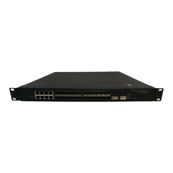
Chapter 3 Port Configuration 3.1 Introduction to Port ES4626/ES4650 Switch comes with 8 Gigabit Combo ports , 16 SFP Gigabit fiber ports and (for ES4650) 2 SFP 10G fiber ports. The Combo ports can be configured to as either 1000GX-TX ports or Gigabit fiber ports. - Page 134 (9) Configure broadcast storm control function for the switch 1. Enter the Ethernet port configuration mode Explanation Command Interface Mode Enters the network port configuration interface ethernet <interface-list> mode. 2. Configure the properties for the Ethernet ports Explanation Command Interface Mode Sets the combo port mode (combo ports combo-forced-mode { copper-forced only);...
- Page 135 Enables the storm control function for broadcasts, multicasts and unicasts with unknown destinations (short rate-suppression {dlf | broadcast | broadcast), sets allowed multicast} <packets> broadcast packet number; the “no” format of this command disables the broadcast storm control function. 3.2.1.2 Commands for Network Port Configuration 3.2.1.2.1 combo-forced-mode Command:combo-forced-mode {copper-forced | copper-preferred-auto | sfp-forced | sfp-preferred-auto }...
- Page 136 Copper Copper Fiber cable Fiber cable Both fiber and copper cable port cable port port port are connected Copper Fiber cable Neither fiber Fiber cable Fiber cable cable port port copper port port connected Note: Combo port is a conception involving the physical layer and the LLC sublayer of the datalink layer.
- Page 137 Command Mode:interface Mode Default:No port name by default Usage Guide:This command is for helping the use manage switches, such as the user assign names according to the port application, e.g. financial as the name of 1/1-2 ports which is used by financial department, engineering as the name of 1/9 ports which belongs to the engineering department, while the name of 1/12 ports is assigned with Server, which is because they connected to the server.
- Page 138 Function: Sets the cable types supported by the Ethernet port; the “no mdi” command sets the cable type to auto-identification. This command is not supported on ES4626/ES4650’s ports of 1000Mbps or more, these ports have auto-identification set for cable types.
- Page 139 no negotiation Function: Enables/Disables the auto-negotiation function of a 1000Base-T port. Parameters: None. Command mode: Port configuration Mode Default: Auto-negotiation is enabled by default. Usage Guide: This command applies to 1000Base-T interface only. The negotiation command is not available for 1000Base-FX interface. For combo port, this command applies to the 1000Base-TX port only and has no effect on 1000Base-TX port.
- Page 140 3.2.1.2.10 rate-suppression Command: rate-suppression {dlf | broadcast | multicast} <packets> no rate-suppression {dlf | broadcast | multicast} Function:Sets the traffic limit for broadcasts, multicasts and unknown destination unicasts on all ports in the switch; the “no rate-suppression” command disables this traffic throttle function on all ports in the switch, i.e., enables broadcasts, multicasts and unknown destination unicasts to pass through the switch at line speed.
- Page 141 SFP/XFP if the port plugged with it; while for vlan interfaces, the port MAC address, IP address and the statistic state of the data packet will be shown; for aggregated port, port speed rate, duplex mode, flow control switch state, broadcast storm restrain of the port and the statistic state of the data packets will be displayed.
-
Page 142: Vlan Interface Configuration
port; master to force the 1000Mb port to be master mode; slave to force the 1000Mb port to be slave mode. Command mode: Interface Mode Default: Auto-negotiation for speed and duplex mode is set by default. Usage Guide: This command applies to 1000Base-TX ports only. speed-duplex command is not available for 1000Base-X port. - Page 143 Configures the VLAN interface IP address; the “no ip address ip address <ip-address> <mask> [secondary] [<ip-address> <mask>]” no ip address [<ip-address> <mask>] command deletes the VLAN interface IP address. VLAN Mode Enables/Disables VLAN Shutdown interface no shutdown 3.2.2.2 Commands for Vlan Interface 3.2.2.2.1 interface vlan Command: interface vlan <vlan-id>...
-
Page 144: Network Management Port Configuration
IP addresses. Both primary IP address and secondary IP addresses can be used for SNMP/Web/Telnet management. In addition, ES4626/ES4650 allows IP addresses to be obtained through BootP/DHCP. Example: Setting the IP address of VLAN1 interface to 192.168.1.10/24. Switch(Config-If-Vlan1)#ip address 192.168.1.10 255.255.255.0 3.2.2.2.3 shutdown... - Page 145 Network Management Port Configuration Enables/Disables network management shutdown port no shutdown Sets network management port speed speed {auto| force10| force100| } Sets network management port duplex duplex {auto| full| half} mode Enables/Disables loopback test function loopback for network management port no loopback ip address <ip-address>...
- Page 146 Command mode: Global Mode Usage Guide: Run the exit command to exit the network management Interface Mode to Global Mode. Example: Entering network management interface mode. Switch(Config)#interface ethernet 0 Switch(Config-Ethernet0)# 3.2.3.2.3 ip address Command: ip address <ip-address> <mask> no ip address [<ip-address> <mask>] Function: Sets the IP address and mask for the switch;...
-
Page 147: Port Mirroring Configuration
Command mode: Network management port configuration Mode Default: Network management port is open by default. Usage Guide: When network management port is shut down, no data frames are sent in the port, and the port status displayed when the user typed “show interface” command is “down”. -
Page 148: Port Mirroring Configuration Task List
ES4626/ES4650 support one mirror destination port only. The number of mirror source ports are not limited, one or more may be used. Multiple source ports can be within the same VLAN or across several VLANs. The destination port and source port(s) can be located in different VLANs. -
Page 149: Device Mirroring Troubleshooting
but also the sent and received flows are available on single mirror source port. While mirroring several ports, their direction can vary but have to be configured by several times. The speed rate of the mirror source port and the destination port should be the same or else the packet may be lost. -
Page 150: Port Configuration Example
3.4 Port Configuration Example SwitchA SwitchB 1/12 1/10 SwitchC Fig 3-1 Port Configuration Example No VLAN has been configured in the switches, default VLAN1 is used. Switch Port Property SwitchA Ingress bandwidth limit: 150 M SwitchB Mirror source port 100Mbps full, mirror source port 1/12 1000Mbps full, mirror destination port SwitchC... -
Page 151: Port Troubleshooting
3.5 Port Troubleshooting Here are some situations that frequently occurs in port configuration and the advised solutions: Two connected fiber interfaces won’t link up if one interface is set to auto-negotiation but the other to forced speed/duplex. This is determined by IEEE 802.3. -
Page 152: Bandwidth Control
enabled flow control. Loopback: Sets up Ethernet port to enable loopback testing function. Example: Assign port to be Ethernet 1/1 and set up MDI as normal; Admin control status as no shutdown, speed/duplex as auto, port flow control status as disabled flow control and Loopback as no loopback. -
Page 153: Vlan Interface Configuration
control and receiving data packet with 100M. 3.6.4 Vlan interface configuration Click Port configuration, vlan interface configuration to open the VLAN port configuration management list to allocate IP address and mask on L3 port and so on. 3.6.5 Allocate IP address for L3 port Click “Port configuration”, “vlan interface configuration”, Allocate IP address for L3 port to allocate IP address for L3 port. -
Page 154: Port Mirroring Configuration
3.6.7 Port mirroring configuration Click “Port configuration”, “Port mirroring configuration” to enter port mirroring configuration management table to do port mirroring configurations. 3.6.8 Mirror configuration Click Port configuration, Port mirroring configuration, Mirror configuration to configure port mirroring function including configuring mirroring source port and mirroring destination port functions. -
Page 155: Show Port Information
maintenance management list to get port information. 3.6.10 Show port information Click “Port configuration”, “Port debug” and “maintenance”, Show port information to check the statistic information of the receiving/sending data packet information of the port. -
Page 156: Chapter 4 Port Channel Configuration
Channel fails, the other ports will undertake traffic of that port through a traffic allocation algorithm. This algorithm is carried out by the hardware. ES4626/ES4650 switch offers 2 methods for configuring port aggregation: manual Port Channel creation and LACP (Link Aggregation Control Protocol) dynamic Port... -
Page 157: Port Channel Configuration Task List
8 port groups and 8 ports in each port group are supported. Once ports are aggregated, they can be used as a normal port. ES4626/ES4650 switch have a built-in aggregation interface configuration mode, the user can perform related configuration in this mode just like in the VLAN and physical port configuration mode. -
Page 158: Commands For Port Channel
Command Explanation Interface Mode port-group <port-group-number> mode Adds ports to the port group and sets their {active|passive|on} mode. no port-group <port-group-number> 3. Enter port-channel configuration mode. Command Explanation Global Mode interface port-channel Enters port-channel configuration mode. <port-channel-number> 4.3 Commands for port channel 4.3.1 debug lacp Command: debug lacp no debug lacp... -
Page 159: Port-Group Mode
otherwise, the group will be deleted. Parameters: <port-group-number> is the group number of a port channel from 1 to 8, if the group number is already exist, an error message will be given. dst-mac performs load balancing according to destination MAC; src-mac performs load balance according to source MAC;... -
Page 160: Interface Port-Channel
both ends are added in “passive” mode, the ports will never aggregate. Example: Under the Port Mode of Ethernet1/1, add current port to “port-group 1” in “active” mode. Switch(C onfig-Ethernet1/1)#port-group 1 mode active 4.3.4 interface port-channel Command: interface port-channel <port-channel-number> Function: Enters the port channel configuration mode Command mode: Global Mode Usage Guide: On entering aggregated port mode, configuration to GVRP or spanning... - Page 161 Number of port-channels : 0 Max port-channels : 1 Displayed information Explanation Number of ports in group Port number in the port group Maxports Maximum number of ports allowed in a group Number of port-channels Whether aggregated to port channel or not Max port-channels Maximum port channel number can be formed by port group.
- Page 162 partner_oper_port_state: _TA___F_ Displayed information Explanation portnumber Port number actor_port_agg_id The channel number to add the port to. If the port cannot be added to the channel due to inconsistent parameters between the port and the channel, 3 will be displayed. partner_oper_sys System ID of the other end.
- Page 163 Distributing Defaulted Expired Partner part Administrative Operational system 000000-000000 000000-000000 system priority 0x8000 0x8000 0x0001 0x0001 port number port priority 0x8000 0x8000 port state LACP activity LACP timeout Aggregation Synchronization Collecting Distributing Defaulted Expired Selected Unselected Displayed information Explanation portnumber Port number port priority Port Priority...
-
Page 164: Port Channel Example
SwitchB Fig 4-2 Configuring Port Channel in LACP Example: The switches in the description below are all ES4626/ES4650 switch and as shown in the figure, ports 1, 2, 3, 4 of SwitchA are access ports that belong to vlan1. Add those four ports to group1 in active mode. Ports 1, 2, 3, 4 of SwitchB are access... - Page 165 ports that also belong to vlan1. Add these four ports to group2 in passive mode. All the ports should be connected with cables (shown as the four connecting lines in the figure) The configuration steps are listed below: SwitchA#config SwitchA (Config)#interface eth 1/1-4 SwitchA (Config-Port-Range)#port-group 1 mode active SwitchA (Config-Port-Range)#exit SwitchA (Config)#interface port-channel 1...
-
Page 166: Port Channel Troubleshooting
SwitchA#config SwitchA (Config)#interface eth 1/1 SwitchA (Config-Ethernet1/1)# port-group 1 mode on SwitchA (Config-Ethernet1/1)#exit SwitchA (Config)#interface eth 1/2 SwitchA (Config-Ethernet1/2)# port-group 1 mode on SwitchA (Config-Ethernet1/2)#exit SwitchA (Config)#interface eth 1/3 SwitchA (Config-Ethernet1/3)# port-group 1 mode on SwitchA (Config-Ethernet1/3)#exit SwitchA (Config-Ethernet1/4)# port-group 1 mode on SwitchA (Config-Ethernet1/4)#exit SwitchB#config SwitchB (Config)#port-group 2... -
Page 167: Web Management
When port-channel is forced, as the aggregation is triggered manually, the port group will stay unaggregated if aggregation fails due to inconsistent VLAN information. Ports must be added to or removed from the group to trigger another aggregation, if VLAN information inconsistency persists, the aggregation will fail again. - Page 168 Click LACP port configuration to enter configuration page Click Apply button to add port into the group. Display port member Select a group num in port configuration and the information of port member will be shown under the configuration table. Port: name of port member Port mode: active or passive...
-
Page 169: Chapter 5 Vlan Configuration
IEEE announced IEEE 802.1Q protocol to direct the standardized VLAN implementation, and the VLAN function of ES4626/ES4650 switch is implemented following IEEE 802.1Q. The key idea of VLAN technology is that a large LAN can be partitioned into many separate broadcast domains dynamically to meet the demands. -
Page 170: Vlan Configuration Task List
Lowering network cost Enhancing network security VLAN and GVRP (GARP VLAN Registration Protocol) defined by 802.1Q are implemented in ES4626/ES4650 switch. The chapter will describe the use and configuration of VLAN and GVRP in details. 5.1.2 VLAN Configuration Task List 1. - Page 171 Command Explanation Interface Mode Set/delete VLAN allowed to be crossed by Trunk. The “no” switchport trunk allowed vlan {<vlan-list>|all} command restores the default no switchport trunk allowed vlan <vlan-list> setting. switchport trunk native vlan <vlan-id> Set/delete PVID for Trunk port. no switchport trunk native vlan 5.
-
Page 172: Commands For Vlan Configuration
5.1.3 Commands For Vlan Configuration 5.1.3.1 vlan Command: vlan <vlan-id>[name <vlan-name>] no vlan <vlan-id>[name] Function: Create a VLAN and enter VLAN configuration mode, and can set VLAN name. In VLAN Mode, the user can assign the switch ports to the VLAN. The “no vlan <vlan-id>“... - Page 173 Ethernet ports their member ports. Normal VLAN will clear its Ethernet ports when set to Private VLAN. It is to be noted Private VLAN messages will not be transmitted by GVRP. Example: Set VLAN100、 200、 300 to private vlans, with respectively primary、 Isolated、 Community types.
- Page 174 for VLAN ID of the VLAN to display status information, the valid range is 1 to 4094; <vlan-name> is the VLAN name for the VLAN to display status information, valid length is 1 to 11 characters. Command mode: Admin Mode Usage Guide: If no <vlan-id>...
- Page 175 Parameter: <vlan-id> is the VID for the VLAN to be added the current port, valid range is 1 to 4094. Command mode: Interface Mode Default: All ports belong to VLAN1 by default. Usage Guide: Only ports in Access mode can join specified VLANs, and an Access port can only join one VLAN at a time.
- Page 176 Switch(Config)#interface ethernet 1/5 Switch(Config-ethernet1/5)#switchport mode trunk Switch(Config-ethernet1/5)#exit Switch(Config)#interface ethernet 1/8 Switch(Config-ethernet1/8)#switchport mode access Switch(Config-ethernet1/8)#exit 5.1.3.8 switchport trunk allowed vlan Command: switchport trunk allowed vlan {<vlan-list>|all} no switchport trunk allowed vlan Function: Set trunk port to allow VLAN traffic; the “no switchport trunk allowed vlan” command restores the default setting.
-
Page 177: Typical Vlan Application
Switch(Config-ethernet1/5)#switchport trunk native vlan 100 Switch(Config-ethernet1/5)#exit 5.1.3.10 switchport ingress-filtering Command: switchport ingress-filtering no switchport ingress-filtering Function: Enable the VLAN ingress rule for a port; the “no vlan ingress disable” command disables the ingress rule. Command mode: Interface Mode Default: VLAN ingress rules are enabled by default. Usage Guide: When VLAN ingress rules are enabled on the port, when the system receives data it will check source port first, and forwards the data to the destination port if it is a VLAN member port. - Page 178 The existing LAN is required to be partitioned to 3 VLANs due to security and application requirements. The three VLANs are VLAN2, VLAN100 and VLAN200. Those three VLANs are cross two different location A and B. One switch is placed in each site, and cross-location requirement can be met if VLAN traffic can be transferred between the two switches.
-
Page 179: Gvrp Configuration
Switch(Config-Vlan200)#switchport interface ethernet 1/8-10 Switch(Config-Vlan200)#exit Switch(Config)#interface ethernet 1/11 Switch(Config-Ethernet1/11)#switchport mode trunk Switch(Config-Ethernet1/11)#exit 5.2 GVRP Configuration 5.2.1 Introduction to GVRP GARP (Generic Attribute Registration Protocol) can be used to dynamically distribute, populate and register property information between switch members within a switch network, the property can be VLAN information, Multicast MAC address of the other information. -
Page 180: Commands For Gvrp
Command Explanation Interface Mode bridge-ext garp timer join <timer-value> no bridge-ext garp timer join Configure the hold, join bridge-ext garp timer leave <timer-value> and leave timers for GARP. no bridge-ext garp timer leave bridge-ext garp timer hold <timer-value> no bridge-ext garp timer hold Global Mode Configure the leave all bridge-ext garp timer leave all <timer-value>... - Page 181 Switch(Config)#exit 5.2.3.2 debug gvrp Command: debug gvrp no debug gvrp Function: Enable the GVRP debugging function: the “ no debug gvrp” command disables the function. Command mode: Admin Mode Default: GVRP debug information is disabled by default. Usage Guide: Use this command to enable GVRP debugging, GVRP packet processing information can be displayed.
- Page 182 Usage Guide: GARP application entity sends a join message after join timer over, other GARP application entities received the join message will register this message. Example: Set the GARP join timer value of port 1/10 to 1000 ms. Switch(Config-Ethernet1/10)#bridge-ext garp timer join 1000 5.2.3.5 bridge-ext garp timer leave Command:bridge-ext garp timer leave <timer-value>...
-
Page 183: Typical Gvrp Application
5.2.3.7 show garp timer Command: show garp timer [<interface-name>] Function: Display the global and port information for GARP. Parameter: <interface-nam> stands for the name of the Trunk port to be displayed. Command mode: Admin Mode Usage Guide: N/A. Example: Display global GARP information. Switch #show garp timer 5.2.3.8 show gvrp configuration Command: show gvrp configuration [<interface-name>]... - Page 184 Switch A Switch B Switch C Fig 5-3 Typical GVRP Application Topology To enable dynamic VLAN information register and update among switches, GVRP protocol is to be configured in the switch. Configure GVRP in Switch A, B and C, enable Switch B to learn VLAN100 dynamically so that the two workstation connected to VLAN100 in Switch A and C can communicate with each other through Switch B without static VLAN100 entries.
-
Page 185: Gvrp Troubleshooting
The GARP counter setting in for Trunk ports in both ends of Trunk link must be the same, otherwise GVRP will not work properly.It is recommended to avoid enabling GVRP and RSTP at the same time in ES4626/ES4650 switch. If GVRP is to be enabled, RSTP function for the ports must be disabled first. - Page 186 Dot1q-tunnel is also called QinQ (802.1Q-in-802.1Q), which is an expansion of 802.1Q. Its dominating idea is encapsulating the customer VLAN tag (CVLAN tag) to the service provider VLAN tag (SPVLAN tag). Carrying the two VLAN tags the packet is transmitted through the backbone network of the ISP internet, so to provide a simple layer-2 tunnel for the users.
-
Page 187: Dot1Q-Tunnel Configuration
The user network is considerably independent. When the ISP internet is upgrading their network, the user networks do not have to change their original configuration. Detailed description on the application and configuration of dot1q-tunnel of ES4626 will be provided in this section 5.3.2 Dot1q-tunnel Configuration 5.3.2.1 Configuration task sequence of Dot1q-tunnel... - Page 188 (referred to as tag) will be packed with a tag when entering through the port; those with tag will be packed with an external tag. The TPID in the tag is 8100 and the VLAN ID is the VLAN ID the port belongs to. Data packets with double tags will be forwarded according to MAC address and external tag, till the external tag is removed when transmitted outside from the access port.
-
Page 189: Typical Applications Of The Dot1Q-Tunnel
Usage Guide: This command is used for displaying the information of the ports at dot1q-tunnel state. Example: Display current dot1q-tunnel state. Switch#show dot1q-tunnel Interface Ethernet1/1: dot1q-tunnel is enable Interface Ethernet1/3: dot1q-tunnel is enable 5.3.4 Typical Applications Of The Dot1q-tunnel Scenario Edge switch PE1 and PE2 of the ISP internet forward the VLAN200~300 data between CE1 and CE2 of the client network with VLAN3. -
Page 190: Dot1Q-Tunnel Troubleshooting
Switch (Config-Ethernet1/1)# exit Switch (Config)#interface ethernet 1/10 Switch (Config-Ethernet1/10)#switchport mode trunk Switch (Config-Ethernet1/10)#dot1q-tunnel tpid 9100 Switch (Config-Ethernet1/10)#exit Switch (Config)# PE2: Switch (Config)#vlan 3 Switch (Config-Vlan3)#switchport interface ethernet 1/1 Switch (Config-Vlan3)#exit Switch (Config)#interface ethernet 1/1 Switch (Config-Ethernet1/1)# dot1q-tunnel enable Switch (Config-Ethernet1/1)# exit Switch (Config)#interface ethernet 1/10 Switch (Config-Ethernet1/10)#switchport mode trunk Switch (Config-Ethernet1/10)#exit... -
Page 191: Vlan-Translation Configuration
ID to new VLAN ID according to the user requirements so to exchange data across different VLANs. The VLAN translation is classified to ingress translation and egress translation, respectively translation the VLAN ID at the entrance or exit. Application and configuration of VLAN translation will be explained in detail in this section. - Page 192 Command: show vlan-translation Function: Display the information of all the ports at VLAN-translation state. Parameter: None. Command Mode: Admin Mode. Usage Guide: Display the information of all the ports at VLAN-translation state, including enabling, packet dropped, direction and other information. Example: Display current VLAN translation state information.
-
Page 193: Typical Application Of Vlan-Translation
Switch(Config-If-Ethernet4/1)#exit Switch(config)# 5.4.3.3 vlan-translation enable Command: vlan-translation enable no vlan-translation enable Function: Enable VLAN translation on specified trunk port of the switch; the “no vlan-translation enable” command restores to the default value. Parameter: None. Command Mode: Port Mode. Default: VLAN translation has not been enabled on the port by default. Usage Guide: To apply VLAN translation on the port the dot1q-tunnel function must be first enabled and configured at trunk port. -
Page 194: Vlan-Translation Troubleshooting
5.5 Dynamic VLAN Configuration 5.5.1 Dynamic VLAN Introduction The dynamic VLAN is named corresponding to the static VLAN (namely the port based VLAN). Dynamic VLAN supported by the ES4626/ES4650 switch includes MAC-based VLAN, IP-subnet-based VLAN and Protocol-based VLAN. Detailed description is as follows... -
Page 195: Dynamic Vlan Configuration
The MAC-based VLAN division is based on the MAC address of each host, namely every host with a MAC address will be assigned to certain VLAN. By the means, the network user will maintain his membership in his belonging VLAN when moves from a physical location to another. - Page 196 Command Explanation Global Mode Add/delete the correspondence mac-vlan <mac-addrss> vlan between the MAC address and the <vlan-id> priority <priority-id> VLAN, namely specified MAC address no mac-vlan {mac <mac-addrss>|all} join/leave specified VLAN 3. Configure the IP-subnet-based VLAN function on the port Command Explanation Port Mode...
- Page 197 5.5.2.2 Commands for Dynamic VLAN Configuration 5.5.2.2.1 dynamic-vlan mac-vlan prefer Command: dynamic-vlan mac-vlan prefer Function:Set the MAC-based VLAN preferred. Parameter: None Command Mode: Global Mode Default: MAC-based VLAN is preferred by default Usage Guide: Configure the preference of dynamic-vlan on switch. The default priority sequence is MAC-based VLAN、IP-subnet-based VLAN、Protocol-based VLAN, namely the preferred order when several dynamic VLAN is available.
- Page 198 1~4094;priority-id is the level of priority and is used in the VLAN tag with a valid range of 0~7;all refers to all the MAC addresses. Command Mode: Global Mode Default: No MAC address joins the VLAN by default. Usage Guide:With this command user can add specified MAC address to specified VLAN.
- Page 199 5.5.2.2.5 show dynamic-vlan prefer Command: show dynamic-vlan prefer Function: Display the preference of the dynamic VLAN Parameter: None Command Mode: Admin Mode Usage Guide: Display the dynamic VLAN preference Example: Display current dynamic VLAN preference Switch #show dynamic-vlan prefer Mac Vlan/Voice Vlan IP Subnet Vlan Proto Vlan 5.5.2.2.6 show mac-vlan...
- Page 200 Function: Display the configuration of Protocol-based VLAN on the switch Parameter: None Command Mode: Admin Mode Usage Guide: Display the configuration of Protocol-based VLAN on the switch Example: Display the configuration of the current Protocol-based VLAN Switch #show protocol-vlan Protocol_Type VLAN_ID ----------------------------- -------...
- Page 201 <vlan-id> priority <priority-id> no subnet-vlan {ip-address <ipv4-addrss> mask <subnet-mask>|all} Function: Add a correspondence between the IP subnet and the VLAN, namely add specified IP subnet into specified VLAN; the “no" form of this command deletes all/the correspondence. Parameter: ipv4-address is the IPv4 address shown in dotted decimal notation; the valid range of each section is 0~255;subnet-mask is the subnet mask code shown in dotted decimal notation;...
-
Page 202: Typical Application Of The Dynamic Vlan
5.5.2.2.13 switchport subnet-vlan enable Command: switchport subnet-vlan enable no switchport subnet-vlan enable Function: Enable the IP-subnet-based VLAN on the port; the “no” form of this command disables the IP-subnet-based VLAN function on the port Parameter: None Command Mode: Port Mode. Default: The IP-subnet-based VLAN is enabled on the port by default Usage Guide: After adding the IP subnet to specified VLAN, the IP-subnet-based... -
Page 203: Dynamic Vlan Troubleshooting
Fig 5-5 Typical topology application of dynamic VLAN Configuration Configuration Explanation Items MAC-based Global configuration on Switch A, Switch B, Switch C VLAN Configuration procedure Switch A, Switch B, Switch C: Switch(Config)#mac-vlan mac 00-03-0f-11-22-33 vlan 100 priority 0 Switch (Config)#exit 5.5.4 Dynamic VLAN Troubleshooting On the switch configured with dynamic VLAN, if the two connected equipment (e.g. -
Page 204: Voice Vlan Configuration
5.6 Voice VLAN Configuration 5.6.1 Voice VLAN Introduction Voice VLAN is specially configured for the user voice data traffic. By setting a Voice VLAN and adding the ports of the connected voice equipments to the Voice VLAN, the user will be able to configure QoS (Quality of service) service for voice data, and improve the voice data traffic transmission priority to ensure the calling quality The switch can judge if the data traffic is the voice data traffic from specified equipment according to the source MAC address field of the data packet entering the port. - Page 205 Command Explanation Global Mode voice-vlan mac <mac-address> mask <mac-mask> priority <priority-id> [name Specify certain voice equipment <voice-name>] join/leave the Voice VLAN voice-vlan {mac <mac-address> mask <mac-mask>|name <voice-name> |all} 3. Enable the Voice VLAN of the port Command Explanation Port Mode Enable/disable the Voice VLAN switchport voice-vlan enable function on the port...
- Page 206 disables Voice VLAN function on the port Parameter: None Command Mode: Port Mode Default:Voice VLAN is enabled by default Usage Guide:When voice equipment is added to the Voice VLAN, the Voice VLAN is enabled globally by default. This command disables Voice VLAN on specified port to meet specified application of the user.
-
Page 207: Typical Applications Of The Voice Vlan
Function: Configure the specified VLAN to Voice VLAN; the “no voice-vlan " command cancels the Voice VLAN configuration of this VLAN Parameter: Vlan id is the number of the specified VLAN Command Mode:Global Mode Default: No Voice VLAN is configured by default Usage Guide:Set specified VLAN for Voice VLAN, There can be only one Voice VLAN at the same time. -
Page 208: Voice Vlan Troubleshooting
Voice VLAN Global configuration on the Switch Configuration procedure Switch A: Switch(Config)#vlan 100 Switch(Config-Vlan100)#exit Switch(Config)#voice-vlan vlan 100 Switch(Config)#voice-vlan mac 00-03-0f-11-22-33 mask 255 priority 5 name company Switch(Config)#voice-vlan mac 00-03-0f-11-22-55 mask 255 priority 5 name company Switch(Config)#interface ethernet 1/10 Switch(Config-If-Ethernet1/10)#switchport mode trunk Switch(Config-If-Ethernet1/10)#exit 5.6.4 Voice VLAN Troubleshooting Voice VLAN can not be applied concurrently with MAC-base VLAN... -
Page 209: Chapter 6 Mac Table Configuration
Chapter 6 MAC Table Configuration 6.1 Introduction to MAC Table MAC table is a table identifies the mapping relationship between destination MAC addresses and switch ports. MAC addresses can be categorized as static MAC addresses and dynamic MAC addresses. Static MAC addresses are manually configured by the user, have the highest priority and are permanently effective (will not be overwritten by dynamic MAC addresses);... - Page 210 PC1 and PC3. And the MAC address mapping entries in the MAC table are deleted after 300 seconds. The 300 seconds here is the default aging time for MAC address entry in ES4626/ES4650 switch. Aging time can be modified in...
-
Page 211: Forward Or Filter
Take the above figure as an example, assuming ES4626/ES4650 switch have learnt the MAC address of PC1 and PC3, and the user manually configured the mapping relationship for PC2 and PC4 to ports. The MAC table of ES4626/ES4650 switch will be: MAC Address... -
Page 212: Mac Address Table Configuration Task List
when the destination MAC address in a unicast frame is not found in the MAC table, the switch will broadcast the unicast frame. When VLANs are configured, the switch will forward unicast frame within the same VLAN. If the destination MAC address is found in the MAC table but belonging to different VLANs, the switch can only broadcast the unicast frame in the VLAN it belongs to. -
Page 213: Mac-Address-Table
Parameter: <age> is the aging-time seconds ,range 10~100000; 0 to disable aging. Command Mode:Global mode Default: Default aging-time is 300 seconds. Usage Guide: The user had better set the aging-time according to the network condition. A too small aging-time will affect the performance of the switch by causing too much broadcast, while a too large aging-time will make the unused entries stay too long in the address table. -
Page 214: Show Mac-Address-Table
6.3.3 show mac-address-table Command: show mac-address-table [static |dynamic |discard| aging-time| multicast| count] [address <WORD>] [vlan <1-4096>] [count] [interface<interface-name>] Function: Show the current MAC table Parameter: static entry; dynamic entry; aging-time address aging time; discard filter entry; multicast entry; <mac-addr> entry’s MAC address; <vlan-id> entry’s VLAN number;... -
Page 215: Troubleshooting
The configuration steps are listed below: 1. Set the MAC address 00-01-11-11-11-11 of PC1 as a filter address. Switch(Config)#mac-address-table static 00-01-11-11-11-11 discard vlan 1. 2.Set the static mapping relationship for PC2 and PC3 to port 7 and port 9, respectively. Switch(Config)#mac-address-table static 00-01-22-22-22-22 interface ethernet 1/7 vlan 1 Switch(Config)#mac-address-table static 00-01-33-33-33-33 interface ethernet 1/9 vlan 1 6.5 Troubleshooting... - Page 216 6.6.1.2 MAC Address Binding Configuration Task List 1. Enable MAC address binding function for the ports 2. Lock the MAC addresses for a port MAC address binding property configuration Enable MAC address binding function for the ports Command Explanation Interface Mode Enable MAC address binding function for the port and lock the port.
- Page 217 Set the maximum number of secure MAC addresses for a port; the “no port-security maximum <value> port-security maximum” command no port-security maximum <value> restores the default value. Set the violation mode for the port; port-security violation {protect the “no port-security violation” shutdown} command restores...
- Page 218 Switch(Config)#interface Ethernet 1/1 Switch(Config-Ethernet1/1)#port security 6.6.1.3.3 port-security convert Command: port-security convert Function: Converts dynamic secure MAC addresses learned by the port to static secure MAC addresses, and disables the MAC address learning function for the port. Command mode: Interface Mode Usage Guide: The port dynamic MAC convert command can only be executed after the secure port is locked.
- Page 219 port is larger than the maximum secure MAC address number set, the setting fails; extra secure static MAC addresses must be deleted, so that the secure static MAC address number is no larger than the maximum secure MAC address number for the setting to be successful.
- Page 220 Switch(Config-Ethernet1/1)#port-security violation shutdown 6.6.1.3.8 show port-security Command: show port-security Function: Display the secure MAC addresses of the port. Command mode: Admin Mode Parameter: <interface-list> stands for the port to be displayed. Usage Guide: This command displays the secure port MAC address information, if no port is specified, secure MAC addresses of all ports are displayed.
- Page 221 -------------------------------------------------------------------------------------------------- Total Addresses : 1 Displayed information Explanation Vlan The VLAN ID for the secure MAC Address Mac Address Secure MAC address Type Secure MAC address type Ports The port that the secure MAC address belongs to Total Addresses Current secure MAC address number in the system.
- Page 222 for the port. Lock Timer Whether locking timer (timer timeout) is enabled for the port. Mac-Learning function Is the MAC address learning function enabled? 6.6.1.4 Binding MAC Address Binding Troubleshooting Enabling MAC address binding for ports may fail in some occasions. Here are some possible causes and solutions: If MAC address binding cannot be enabled for a port, make sure the port is not enabling Spanning tree or port aggregation and is not configured as a Trunk port.
-
Page 223: Chapter 7 Mstp Configuration
Chapter 7 MSTP Configuration 7.1 MSTP Introduction The MSTP (Multiple STP) is a new spanning-tree protocol which is based on the STP and the RSTP. It runs on all the bridges of a bridged-LAN. It calculates a common and internal spanning tree (CIST) for the bridge-LAN which consists of the bridges running the MSTP, the RSTP and the STP. - Page 224 Figure7-1 Example of CIST and MST Region In the above network, if the bridges are running the STP or the RSTP, one port between Bridge M and Bridge B should be blocked. But if the bridges in the yellow range run the MSTP and are configured in the same MST region, MSTP will treat this region as a bridge.
-
Page 225: Port Roles
The MSTI is only valid within its MST region. An MSTI has nothing to do with MSTIs in other MST regions. The bridges in a MST region receive the MST BPDU of other regions through Boundary Ports. They only process CIST related information and abandon MSTI information. - Page 226 Global Mode spanning-tree mode {mstp|stp} Set MSTP running mode no spanning-tree mode Interface Mode Force port migration to run under MSTP spanning-tree mcheck 2. Configure instance parameters Command Explanation Global Mode spanning-tree mst <instance-id> priority bridge priority specified <bridge-priority> instance spanning-tree <instance-id>...
- Page 227 Command Explanation Global Mode Enter MSTP region mode. The “ no spanning-tree mst configuration spanning-tree mst configuration” command restores default no spanning-tree mst configuration setting. MSTP region mode instance <instance-id> vlan <vlan-list> Create Instance and set mapping instance <instance-id> [vlan between VLAN and Instance <vlan-list>] name <name>...
- Page 228 Command Explanation Interface Mode spanning-tree link-type Set the port link type {auto|force-true|force-false} no spanning-tree link-type spanning-tree portfast Set the port to be an boundary port no spanning-tree portfast 6. Configure the format of MSTP Command Explanation Interface Mode Configure format port spanning-tree packet ,...
-
Page 229: Commands For Mstp
Command Explanation Global Mode Enable: the spanning-tree flush once the topology changes. Disable:the spanning tree don’t flush spanning-tree tcflush enable when the topology changes. spanning-tree tcflush disable Protect: spanning-tree flush spanning-tree tcflush protect every ten seconds no spanning-tree tcflush “no spanning-tree tcflush”... -
Page 230: Instance Vlan
to global mode. Command mode: MSTP Region Mode Usage Guide: This command is to quit MSTP region mode with saving the current configuration. Example: Quit MSTP region mode with saving the current configuration. Switch(Config-Mstp-Region)#exit Switch(Config)# 7.3.3 instance vlan Command: instance <instance-id> vlan <vlan-list> no instance <instance-id>... -
Page 231: Revision-Level
restores the default setting. Parameter: <name> is the MSTP region name. The length of the name should be less than 32 characters. Command mode: MSTP Region Mode Default: Default MSTP region name is the MAC address of this bridge. Usage Guide: This command is to set MSTP region name. The bridges with same MSTP region name and same other attributes are considered in the same MSTP region. -
Page 232: Spanning-Tree Format
Switch(Config)#spanning-tree Switch(Config)#interface ethernet 1/2 Switch(Config-Ethernet1/2)#no spanning-tree 7.3.7 spanning-tree format Command:spanning-tree format standard | privacy | auto no spanning-tree format Function:Configure the format of the port packet so to be interactive with products of other companies. Parameter:standard:The packet format provided by IEEE privacy:Privacy packet format, which is compatible with CISCO equipments. -
Page 233: Spanning-Tree Forward-Time
7.3.8 spanning-tree forward-time Command: spanning-tree forward-time <time> no spanning-tree forward-time Function: Set the switch forward delay time; The command “no spanning-tree forward-time” restores the default setting. Parameter: <time> is forward delay time in seconds. The valid range is from 4 to 30. Command mode: Global Mode Default: The forward delay time is 15 seconds by default. -
Page 234: Spanning-Tree Maxage
no spanning-tree link-type Function: Set the link type of the current port; The command “no spanning-tree link-type” restores link type to auto-negotiation. Parameter: auto sets auto-negotiation, force-true forces the link as point-to-point type, force-false forces the link as non point-to-point type. Command mode: Interface Mode Default: The link type is auto by default, The MSTP detects the link type automatically. -
Page 235: Spanning-Tree Mcheck
Default: The max hop is 20 by default. Usage Guide: The MSTP uses max-age to count BPDU lifetime. In addition, MSTP also uses max-hop to count BPDU lifetime. The max-hop is degressive in the network. The BPDU has the max value when it initiates from MSTI root bridge. Once the BPDU is received, the value of the max-hop is reduced by 1. -
Page 236: Spanning-Tree Mst Configuration
7.3.15 spanning-tree mst configuration Command: spanning-tree mst configuration no spanning-tree mst configuration Function: Enter the MSTP mode. Under the MSTP mode, the MSTP attributes can be set. The command “no spanning-tree mst configuration” restores the attributes of the MSTP to their default values. Command mode: Global Mode Default: The default values of the attributes of the MSTP region are listed as below: Attribute of MSTP... -
Page 237: Spanning-Tree Mst Port-Priority
For the aggregation ports, the default costs are as below: Port Type Allowed Number Default Port Cost Aggregation Ports 10Mbps 2000000/N 100Mbps 200000/N 1Gbps 20000/N 10Gbps 2000/N Usage Guide: By setting the port cost, users can control the cost from the current port to the root bridge in order to control the elections of root port and the designated port of the instance. -
Page 238: Spanning-Tree Portfast
<bridge-priority> sets the switch priority. The valid range is from 0 to 61440. The value should be the multiples of 4096, such as 0, 4096, 8192…61440. Command mode: Global Mode Default: The default bridge priority is 32768. Usage Guide: By setting the bridge priority, users can change the bridge ID for the specified instance. -
Page 239: Spanning-Tree Tcflush (Global Mode)
realize compatibility with these manufactories equipment . Note:Because the authentication string is related to instance ID and VLAN ID, the command may cause recognizing the equipment that with different instance and VLAN relation as in the same region. Before the command is executed, make sure that instance and VLAN relation is accord for all the equipment. -
Page 240: Mstp Example
Command:spanning-tree tcflush {enable| disable| protect} no spanning-tree tcflush Function: Configure the spanning-tree flush mode for port once the topology changes . “no spanning-tree tcflush” restores to default setting Parameter: Enable:the spanning-tree flush once the topology changes. Disable:the spanning tree don’t flush when the topology changes. Protect: the spanning-tree flush every ten seconds Default: Global configuration Command mode: Interface mode... - Page 241 The connections among the switches are shown in the above figure. All the switches run in the MSTP mode by default, their bridge priority, port priority and port route cost are all in the default values (equal). The default configuration for switches is listed below: Bridge Name SwitchA SwitchB...
- Page 242 The detailed configuration is listed below: SwitchB: SwitchB(Config)#vlan 20 SwitchB(Config-Vlan20)#exit SwitchB(Config)#vlan 30 SwitchB(Config-Vlan30)#exit SwitchB(Config)#vlan 40 SwitchB(Config-Vlan40)#exit SwitchB(Config)#vlan 50 SwitchB(Config-Vlan50)#exit SwitchB(Config)#spanning-tree mst configuration SwitchB(Config-Mstp-Region)#description mstp SwitchB(Config-Mstp-Region)#instance 3 vlan 20;30 SwitchB(Config-Mstp-Region)#instance 4 vlan 40;50 SwitchB(Config-Mstp-Region)#exit SwitchB(Config)#interface e1/1-7 SwitchB(Config-Port-Range)#switchport mode trunk SwitchB(Config-Port-Range)#exit SwitchB(Config)#spanning-tree SwitchC: SwitchC(Config)#vlan 20 SwitchC(Config-Vlan20)#exit...
- Page 243 SwitchC(Config)#spanning-tree SwitchC(Config)#spanning-tree mst 3 priority 0 SwitchD: SwitchD(Config)#vlan 20 SwitchD(Config-Vlan20)#exit SwitchD(Config)#vlan 30 SwitchD(Config-Vlan30)#exit SwitchD(Config)#vlan 40 SwitchD(Config-Vlan40)#exit SwitchD(Config)#vlan 50 SwitchD(Config-Vlan50)#exit SwitchD(Config)#spanning-tree mst configuration SwitchD(Config-Mstp-Region)#description mstp SwitchD(Config-Mstp-Region)#instance 3 vlan 20;30 SwitchD(Config-Mstp-Region)#instance 4 vlan 40;50 SwitchD(Config-Mstp-Region)#exit SwitchD(Config)#interface e1/1-7 SwitchD(Config-Port-Range)#switchport mode trunk SwitchD(Config-Port-Range)#exit SwitchD(Config)#spanning-tree SwitchD(Config)#spanning-tree mst 4 priority 0 After the above configuration, SwitchA is the root bridge of the instance 0 of the entire network.
- Page 244 SwitchA SwitchB SwitchC SwitchD Figure 7-3 The Topology Of the Instance 0 after the MSTP Calculation SwitchB SwitchC SwitchD Figure 7-4 The Topology Of the Instance 3 after the MSTP Calculation SwitchB SwitchC SwitchD Figure 7-5 The Topology Of the Instance 4 after the MSTP Calculation...
-
Page 245: Mstp Troubleshooting
7.5 MSTP Troubleshooting In order to run the MSTP on the switch port, the MSTP has to be enabled globally. If the MSTP is not enabled globally, it can’t be enabled on the port. The MSTP parameters co work with each other, so the parameters should meet the following conditions. - Page 246 Ext.RootPathCost : 200000 Region Root Id : this switch Int.RootPathCost : 0 Root Port ID : 128.1 Current port list in Instance 0: Ethernet1/1 Ethernet1/2 (Total 2) PortName ExtRPC IntRPC State Role DsgBridge DsgPort -------------- ------- --------- --------- --- ---- ------------------ ------- Ethernet1/1 128.001 0 FWD ROOT 16384.00030f010f52 128.007 Ethernet1/2 128.002...
- Page 247 Instance Information The priority and the MAC address of the current bridge for Self Bridge Id the current instance Root Id The priority and the MAC address of the root bridge for the current instance Ext.RootPathCost Total cost from the current bridge to the root of the entire network Int.RootPathCost Cost from the current bridge to the region root of the current...
- Page 248 ---------------------------------- 7.5.1.3 show mst-pending Command: show mst-pending Function: In the MSTP region mode, display the configuration of the current MSTP region. Command mode: MSTP Region Mode Usage Guide: In the MSTP region mode, display the configuration of the current MSTP region such as MSTP name, revision, VLAN and instance mapping.
-
Page 249: Web Management
Switch#debug spanning-tree Switch#debug spanning-tree bpdu rx interface e1/1 7.6 Web Management Click “MSTP control” to enter MSTP control configuration mode to manage MSTP features for the switch. 7.6.1 MSTP field operation Click “MSTP control” to enter MSTP field operation. 7.6.1.1 Instance configuration Click “MSTP control”... -
Page 250: Mstp Port Operation
7.6.2 MSTP port operation 7.6.2.1 Edge port setting Click “MSTP control” to enter MSTP field operation, then "PortFast Config". Set the port to be an edge port Configure port 1/1 to be edge ports. 7.6.2.2 Port priority setting Click “MSTP control” to enter MSTP port operation, then "Port Priority Config". Set the priority for the current port on specified instance Set the priority for port 1/1 of instance1 to 32. -
Page 251: Mstp Global Control
7.6.2.5 Link type configuration Click “MSTP control” to enter MSTP port operation, then "Link_Type Config". Set the link type of the current port. Set the link of port 1/1 to be forced point-to-point type. 7.6.2.6 MSTP port configuration Click “MSTP control” to enter MSTP port operation, then "MSTP Agreement Port Config". Run the command to enable MSTP under the switch port configuration mode. -
Page 252: Show Mstp Setting
7.6.3.3 Hello_time configuration Click “MSTP control” to enter MSTP Global control, then "Hello_time Config". Set the Hello time for the switch. Set MSTP Hello time to 5 seconds in Global Mode. 7.6.3.4 Set the max age time for BPDU information in the switch Click “MSTP control”, MSTP Global Control, then enter the switch BPDU message "Max Age Time Config". - Page 253 Click MSTPL control, “show MSTP settings”, enter "Instance Information". Display MSTP and instances information. Display Instance0 MSTP information. 7.6.4.2 MSTP field information Click “MSTP control”, “show MSTP setting”, enter "MSTP Field Information". Display effective MSTP field parameter configurations.
-
Page 254: Chapter 8 Qos And Pbr Configuration
Chapter 8 QoS And PBR Configuration 8.1 QoS Configuration 8.1.1 Introduction to QoS QoS (Quality of Service) is a set of capabilities that allow you to create differentiated services for network traffic, thereby providing better service for selected network traffic. QoS is a guarantee for service quality of consistent and predictable data transfer service to fulfill program requirements. - Page 255 IP Precedence: IP priority.Classification information carried in Layer 3 IP packet header, occupying 3 bits, in the range of 0 to 7. DSCP: Differentiated Services Code Point, classification information carried in Layer 3 IP packet header, occupying 6 bits, in the range of 0 to 63, and is downward compatible with IP Precedence.
- Page 256 and may discard some low priority packets in case of bandwidth shortage. If devices of each hop in a network support differentiated service, an end-to-end QoS solution can be created. QoS configuration is flexible, the complexity or simplicity depends on the network topology and devices and analysis to incoming/outgoing traffic. 8.1.1.3 Basic QoS Model The basic QoS consists of five parts: Classification, Policing, Remark, Queuing and Scheduling, where classification, policing and remark are sequential ingress actions, and...
- Page 257 Fig 8-4 Classification process Policing and remark: Each packet in classified ingress traffic is assigned an internal DSCP value and can be policed and remarked. Policing can be performed based on DSCP value to configure different policies that allocate bandwidth to classified traffic. If the traffic exceeds the bandwidth set in the policy (out of profile), the out of profile traffic can be allowed, discarded or remarked.
- Page 258 Fig 8-5 Policing and Remarking process Queuing and scheduling: Packets at the egress will re-map the internal DSCP value to CoS value, the queuing operation assigns packets to appropriate queues of priority according to the CoS value; while the scheduling operation performs packet forwarding according to the prioritized queue weight.
-
Page 259: Qos Configuration Task List
Fig 8-6 Queuing and Scheduling process 8.1.2 QoS Configuration Task List 1. Enable QoS QoS can be enabled or disabled in Global Mode. QoS must be enabled first in Global Mode to configure the other QoS commands. 2. Configure class map. Set up a classification rule according to ACL, VLAN ID, IP Precedence or DSCP to classify the data stream. - Page 260 3. Configure a policy map. After data steam classification, a policy map can be created to associate with the class map created earlier and enter class mode. Then different policies (such as bandwidth limit, priority degrading, assigning new DSCP value) can be applied to different data streams.
- Page 261 Global Mode Create a policy map and enter policy policy-map <policy-map-name> map mode; the “no policy-map no policy-map <policy-map-name> command <policy-map-name>” deletes the specified policy map. After a policy map is created, it can be class <class-map-name> associated to a class. Different policy no class <class-map-name>...
- Page 262 set. 4. Apply QoS to ports Command Explanation Interface Mode Configure port trust; the “no mls qos trust [cos trust” command disables the current [pass-through-dscp]|dscp trust status of the port. [pass-through-cos]|ip-precedence [pass-through cos]|port priority <cos>] no mls qos trust Configure the default CoS value of the mls qos cos {<default-cos>...
-
Page 263: Commands For Qos
command restores the no wrr-queue cos-map cos-map” default setting. 6. Configure QoS mapping Command Explanation Global Mode Set CoS to DSCP mapping, DSCP to mls qos map {cos-dscp <dscp1...dscp8> | mapping, DSCP DSCP dscp-cos <dscp-list> <cos> mutation mapping, IP precedence to dscp-mutation DSCP and policed DSCP mapping;... - Page 264 no class-map <class-map-name> Function: Creates a class map and enters class map mode; the “no class-map <class-map-name>“ command deletes the specified class map. Parameters: <class-map-name> is the class map name. Default: No class map is configured by default. Command mode: Global Mode Usage Guide: Example: Creating and then deleting a class map named “c1”.
- Page 265 Switch(config-ClassMap)#match ip precedence 0 1 Switch(config-ClassMap)#exit 8.1.3.4 set Command: set {ip dscp <new-dscp> | ip precedence <new-precedence>|ipv6 dscp <new-dscp> | ipv6 flowlabel <new-flowlabel|cos<new cos>>} no set {ip dscp | ip precedence|ipv6 dscp | ipv6 flowlabel |cos<new cos>} Function: Assign a new DSCP, IP Precedence, IPv6 DSCP or IPv6 FL for the classified traffic;...
- Page 266 Function: Configures the default CoS value of the port; the “no mls qos cos” command restores the default setting. Parameters: < default-cos> is the default CoS value for the port, the valid range is 0 to Default: The default CoS value is 0. Command mode: Interface Mode Usage Guide: none Example: Setting the default CoS value of Ethernet port 1/1 to 5, i.e., packets coming in...
- Page 267 Command:mls qos trust [cos [pass-through-dscp]|dscp [pass-through-cos]| ip-precedence [pass-through-cos] |port priority <cos>] [no] mls qos trust Function: Configures port trust; the “no mls qos trust” command disables the current trust status of the port. Parameters: cos configures the port to trust CoS value; cos pass-through-dscp configures the port to trust CoS value but does not change packet DSCP value;...
- Page 268 mu1. Switch(Config)#interface ethernet 1/1 Switch(Config-Ethernet1/1)#mls qos trust dscp pass-through cos Switch(Config-Ethernet1/1)#mls qos dscp-mutation mu1 8.1.3.10 mls qos map Command: mls qos map {cos-dscp <dscp1...dscp8> | dscp-cos <dscp-list> to <cos> | dscp-mutation <dscp-mutation-name> <in-dscp> to <out-dscp> |ip-prec-dscp <dscp1...dscp8> policed-dscp <dscp-list> <mark-down-dscp>} {cos-dscp dscp-cos dscp-mutation...
- Page 269 Default DSCP-to-CoS Map 0–7 8–15 16–23 24–31 32–39 40–47 48–55 56–63 DSCP Value CoS Value Default IP-Precedence-to-DSCP Map IP Precedence Value 16 24 32 40 48 56 DSCP Value dscp-mutation and policed-dscp are not configured by default Command mode: Global Mode Usage Guide: In police command, classified packet traffic can be set to mark down if exceed specified average speed or burst value, policed-dscp <dscp-list>...
- Page 270 Switch(Config-Policy-Class)#police 20000 2000 exceed-action drop Switch(Config-Policy-Class)#exit Switch(Config-PolicyMap)#exit 8.1.3.12 police aggregate Command: police aggregate <aggregate-policer-name> no police aggregate <aggregate-policer-name> Function: Applies a policy set to classified traffic; the “no police aggregate <aggregate-policer-name>“ command deletes the specified policy set. Parameters: <aggregate-policer-name> is the policy set name. Default: No policy set is configured by default.
- Page 271 Parameter: strict configure queue out method to strict priority-queue method; wrr restores the default wrr queue out method. Default: wrr out queue mode Command mode: Interface Mode Usage Guide: When priority-queue queue out mode is used, packets are no longer sent with WRR weighted algorithm, but send packets queue after queue.
-
Page 272: Qos Example
Command mode: Interface Mode Usage Guide: The absolute value of WRR is meaningless. WRR allocates bandwidth by using eight weight values. If a weight is 0, then the queue has the highest priority; when the weights of multiple queues are set to 0, then the queue of higher order has the higher priority. - Page 273 Switch(Config-Ethernet1/1)#mls qos cos 5 Configuration result: When QoS enabled in Global Mode, the egress queue bandwidth proportion of port ethernet 1/1 is 1:1:2:2:4:4:8:8. When packets have CoS value coming in through port ethernet 1/1, it will be map to the queue out according to the CoS value, CoS value 0 to 7 correspond to queue out 1, 2, 3, 4, 5, 6, 7, 8, respectively.
- Page 274 QoS domain Server SwitchC SwitchB SwitchA Fig 8-7 Typical QoS topology As shown in the figure, inside the block is a QoS domain, switchA classifies different traffics and assigns different IP precedences. For example, set IP precedence for packets from segment 192.168.1.0 to 5 on port ethernet 1/1. The port connecting to switchB is a trunk port.
-
Page 275: Qos Troubleshooting
Switch(Config-PolicyMap)#class c1 Switch(Config--Policy-Class)#set ip precedence 5 Switch(Config--Policy-Class)#exit Switch(Config-PolicyMap)#exit Switch(Config)#interface ethernet 1/1 Switch(Config-Ethernet1/1)#service-policy input p1 QoS configuration in SwitchB: SWITCH#CONFIG Switch(Config)#mls qos Switch(Config)#interface ethernet 1/1 Switch(Config-Ethernet1/1)#mls qos trust ip-precedence pass-through-cos 8.1.5 QoS Troubleshooting QoS is disabled on switch ports by default, 8 sending queues are set by default, queue1 forwards normal packets, other queues are used for some important control packets (such as BPDU). - Page 276 Switch # show class-map Class map name:c1 Match acl name:1 Displayed information Explanation Class map name:c1 Name of the Class map Match acl name:1 Classifying rule for the class map. 8.1.5.1.2 show policy-map Command: show policy-map [<policy-map-name>] Function: Displays policy map of QoS. Parameters: <...
- Page 277 referred to 8.1.5.1.4 show mls qos interface Command: show mls qos interface [<interface-id>] [buffers | policers | queueing | statistics] Function: Displays QoS configuration information on a port. Parameters: <interface-id> is the port ID; buffers is the queue buffer setting on the port; policers is the policy setting on the port;...
- Page 278 Queue 1 Queue and weight type: Port QType Ethernet1/2 Displayed information Explanation Cos-queue map: CoS value to queue mapping. Queue and weight type: Queue to weight mapping. QType WFQ or PQ queue out method Switch # show mls qos interface policers ethernet 1/2 Ethernet1/2 Attached policy-map for Ingress: p1 Displayed information...
- Page 279 cos: 0 1 2 3 4 5 6 7 ------------------------------------- dscp: 0 8 16 24 32 40 48 56 IpPrecedence-dscp map: ipprec: 0 1 2 3 4 5 6 7 ------------------------------------- dscp: 0 8 16 24 32 40 48 56 Dscp-cos map: d1 : d2 0 1 2 3 4 5 6 7 8 9 0 0 0 0 0 0 0 0 1 1...
-
Page 280: Pbr Configuration
8.2 PBR Configuration 8.2.1 Introduction to PBR PBR(Policy-Based Routing)is a method which determines the next-hop of the data packets by policy messages such as source address, destination address, IP priority, TOS value, IP protocol, source port No., destination port No, etc. 8.2.2 PBR configuration The PBR configuration task list is as follows: Initiate PBR function... - Page 281 Switch(Config-IP-Ext-Nacl-a1)#deny ip 192.168.1.0 0.0.0.255 192.168.0.0 0.0.255.255 Switch(Config-IP-Ext-Nacl-a1)#exit Switch(config)#mls qos Switch(config)#class-map c1 Switch(config-ClassMap)#match access-group a1 Switch(config-ClassMap)# exit Switch(config)#policy-map p1 Switch(config-PolicyMap)#class c1 Switch(config-Policy-Class)#set ip nexthop 218.31.1.119 Switch(config--Policy-Class)#exit Switch(config-PolicyMap)#exit Switch(config)#interface ethernet Switch(Config-Ethernet1/1)#service-policy input p1 Configuration results First set an ACL a1 with two items. The first item matches source IP segments 192.168.1.0/24 (allowed)...
-
Page 282: Chapter 9 Flow-Based Redirection
Chapter 9 Flow-based Redirection 9.1 Introduction to Flow-based Redirection Flow-based redirection function enables the switch to transmit the data frames meeting some special condition (specified by ACL) to another specified port. The fames meeting a same special condition are called a class of flow, the ingress port of the data frame is called the source port of redirection, and the specified egress port is called the destination port of redirection. -
Page 283: Command For Flow-Based Redirection
2. Check the current flow-based redirection configuration Command Explanation Global mode/Admin mode Display the information of show flow-based-redirect {interface ethernet < current flow-based interface-list > } redirection in the system/port 9.3 Command for Flow-based Redirection 9.3.1 access-group <aclname> redirect to interface ethernet Command:access-group <aclname>... -
Page 284: Flow-Based Redirection Examples
2. specify ports in <interface-list> , display the information of the flow-based redirection configured in the ports listed in the interface-list. Command Mode:Global mode/Admin mode Usage Guide:This command is used to display the information of current flow-based redirection in the system/por Examples:... -
Page 285: Chapter 10 L3 Forward Configuration
ES4626/ES4650 switch can forward IP packets by hardware, the forwarding chip of ES4626/ES4650 switch have a host route table and default route table. Host route table stores host routes to connect to the switch directly; default route table stores network routes (after aggregation algorithm process). -
Page 286: Commands For Layer 3 Interface
Command Explanation Global Mode Creates a VLAN interface (VLAN interface is a Layer 3 interface); the “no interface interface vlan <vlan-id> vlan <vlan-id>” command deletes the no interface vlan <vlan-id> VLAN interface (Layer 3 interface) created in the switch. 10.1.3 Commands for Layer 3 Interface 10.1.3.1 interface vlan Command:interface vlan <vlan-id>... - Page 287 current global scale with the promotion of Internet. However, as Internet infrastructure and Internet application services continue boosting, IPv4 has shown its deficiency when facing the present scale and complexity of Internet. IPv6 refers to the sixth version of Internet protocol which is the next generation Internet protocol designed by IETF to replace the current Internet protocol version 4 (IPv4).
- Page 288 and Path MTU Discovery Mechanism collaborates with data packet source which enhances the processing efficiency of router. Address automatic configuration and plug-and-play is supported. Large amounts of hosts can find network routers easily by address automatic configuration function of IPv6 while obtaining a globally unique IPv6 address automatically as well which makes the devices using IPv6 Internet plug-and-play.
-
Page 289: Ip Configuration
10.2.2 IP Configuration It can configure three-layer interface as IPv4 interface or IPv6 interface. 10.2.2.1 IPv4 Address Configuration Configure the IPv4 address of three-layer interface Command Explanation Interface Mode Configure IP address of VLAN interface; the no ip address ip address <ip-address> <mask> [secondary] [<ip-address>... - Page 290 1. IPv6 basic configuration Globally enable IPv6 (1) Configure interface IPv6 address (2) Configure IPv6 static routing (3) 2. IPv6 Neighbor Discovery Configuration Configure DAD neighbor query message number (1) Configure send neighbor query message interval (2) Enable and forbid router announce (3)...
- Page 291 Configure IPv6 address, including aggregatable global unicast addresses, local site addresses local link ipv6 address <ipv6-address/prefix-length> addresses. [eui-64] ipv6 no ipv6 address <ipv6-address/prefix-length> address <ipv6-address/prefix-length> command cancels IPv6 address. (3). Set IPv6 Static Routing Command Description Global mode [no] ipv6 route <iPv6-prefix/prefix-length> Configure IPv6 static routing.
- Page 292 Interface Configuration Mode Configure Router Announce Lifespan. The NO command resumes default value (1800 [no] ipv6 nd ra-lifetime <seconds> seconds). (5)Configure Router Announce Minimum Interval Command Description Interface Configuration Mode Configure the minimum interval for router [no] ipv6 nd min-ra-interval announce.
- Page 293 Command Admin Mode Global mode Create a tunnel. The NO command deletes a [no] interface tunnel <tnl-id> tunnel. (2)Configure tunnel source Command Admin Mode Tunnel Configuration Mode Configure tunnel source end IPv4 address. [no] tunnel source The NO command deletes the IPv4 address <ipv4-daddress>...
- Page 294 [no] ipv6 route Configure tunnel routing. The NO command <ipv6-address/prefix-length> clears tunnel routing. {<interface-type interface-number> | tunnel <tnl-id>} 10.2.2.4 Commands For IPv6 Configuration 10.2.2.4.1 ipv6 enable Command:[no] ipv6 enable Function:This command enables functions such as Unicast IPv6 Data Packet Transmit, Neighbor Discover, Router Bulletin and Routing Protocol, etc.
- Page 295 Switch(Config-if-Vlan1)#ipv6 address 2001:3f:ed8::99/64 10.2.2.4.3 ipv6 route Command:[no] ipv6 route <ipv6-prefix/prefix-length> {<ipv6-address> |<interface-type interface-number>|{<ipv6-address> <interface-type interface-number>}|tunnel <tunnel no> }} [<precedence>] Function:Set IPv6 static router Parameters:Parameter <ipv6-prefix> is the destination address of IPv6 network static router, parameter length IPv6 prefix, parameter <prefix-length> <ipv6-address>...
- Page 296 Command Mode:Interface Configuration Mode Default:The default request message number is 1 Usage Guide:When configuring an IPv6 address, it is required to process IPv6 Repeat Address Check, this command is used to configure the ND message number of Repeat Address Check to be sent, value being 0 means no Repeat Address Check is executed. Example:The Neighbor Request Message number sent in succession by interface when setting Repeat Address Check is 3..
- Page 297 Function:Configure the lifetime of router announcement Parameter : parameter <seconds> stands for the number of seconds of router announcement lifetime, <seconds> value must be between 9-9000. Command Mode: Interface Configuration Mode Default:The number of seconds of router default announcement lifetime is 1800. Usage Guide:This command is used to configure the lifetime of the router on Layer 3 interface, seconds being 0 means this interface can not be used for default router, otherwise the value should not be smaller than the maximum time interval of sending...
- Page 298 Usage Guide:The maximum time interval of routing announcement should be smaller than the lifetime value routing announcement. Example : Set the maximum time interval of sending routing announcement is 20 seconds. Switch (Config-if-Vlan1)#ipv6 nd max-ra-interval 20 10.2.2.4.10 ipv6 nd prefix Command :...
- Page 299 announcement. Parameter: Parameter < ipv6-prefix> is the address prefix of the specified announcement, parameter < prefix-length> is the length of the address prefix of the specified announcement, parameter < valid-lifetime> is the valid lifetime of the prefix, parameter < preferred-lifetime> is the preferred lifetime of the prefix, and the valid lifetime must be no smaller than preferred lifetime.
- Page 300 10.2.2.4.13 interface tunnel Command:[no] interface tunnel <tnl-id> Function:Create/Delete tunnel. Parameter:Parameter <tnl-id> is tunnel No. Command Mode:Interface Configuration Mode Default :None Usage Guide:This command creates a virtual tunnel interface. Since there is not information such as specific tunnel mode and tunnel source, show ipv6 tunnel does not show the tunnel, enter tunnel mode after creating, under that model information such as tunnel source and destination can be specified.
- Page 301 Datagram size in byte Size of Ping packets Timeout in milli-seconds Time delay allowed Extended commands Settings of extensive parameters Indicate that the network is reachable Success rate is 100 percent (1/1), Statistics information, which shows the rate round-trip min/avg/max = 1/1/1 ms of ping packets arriving successfully is 100%, no loss.
- Page 302 Switch {Config-if-Tunnel1}#tunnel nexthop 178.99.156.8 10.2.2.4.18 tunnel 6to4-relay Command:[no] tunnel 6to4-relay <ipv4-daddress> Function: Configure 6to4 tunnel relay IPv4 address. Parameter:<ipv4-daddress> is 6to4 tunnel relay IPv4 address. Command Mode:Tunnel Configuration Mode Default Situation:None Usage Guide:This command is used to configure 6to4 tunnel relay IPv4 address. The IPv4 address won’t be checked in configuring 6to4 tunnel relay.
-
Page 303: Ip Configuration Examples
10.2.3 IP Configuration Examples 10.2.3.1 Configuration Examples of IPv4 SwitchB PC-A PC-B SwitchA Fig 10-1IPv4 configuration example The user’s configuration requirements are: Configure IPv4 address of different network segments on switch1 and switch2, configure static routing and validate accessibility using ping function. Configuration Description: 1、... - Page 304 SwitchA(Config)#IP route 192.168.3.0 255.255.255.0 192.168.2.2 SwitchB(Config)#interface vlan 2 SwitchB(Config-if-Vlan2)#IP address 192.168.2.2 255.255.2550 SwitchB(Config)#interface vlan 3 SwitchB(Config-if-Vlan3)#IP address 192.168.3.1 255.255.255.0 SwitchB(Config-if-Vlan3)#exit SwitchB(Config)#IP route 192,168.1.0 255.255.255.0 192.168.2.1 10.2.3.2 Configuration Examples of IPv6 Example 1: SwitchB PC-A PC-B SwitchA Fig 10-2 IPv6 configuration example The user’s configuration requirements are: Configure IPv6 address of different network segments on SwitchA and SwitchB, configure static routing and validate reachability using ping6 function.
- Page 305 The configuration procedure is as follows: SwitchA(Config)#ipv6 enable SwitchA(Config)#interface vlan 1 SwitchA(Config-if-Vlan1)#ipv6 address 2001::1/64 SwitchA(Config)#interface vlan 2 SwitchA(Config-if-Vlan2)#ipv6 address 2002::1/64 SwitchA(Config-if-Vlan2)#exit SwitchA(Config)#ipv6 route 2003::33/64 2002::2 SwitchB(Config)#ipv6 enable SwitchB(Config)#interface vlan 2 SwitchB(Config-if-Vlan2)#ipv6 address 2002::2/64 SwitchB(Config)#interface vlan 3 SwitchB(Config-if-Vlan3)#ipv6 address 2003::1/64 SwitchB(Config-if-Vlan3)#exit SwitchB(Config)#ipv6 route 2001::33/64 2002::1 SwitchA#ping6 2003::33 Configuration results:...
- Page 306 interface Vlan3 ipv6 address 2003::1/64 interface Loopback mtu 3924 ipv6 route 2001::/64 2002::1 no login Example 2: SwitchC SwithA SwitchB PC-A PC-B Fig 10-3 IPv6 tunnel This case is IPv6 tunnel with the following user configuration requirements: SwitchA and SwitchB are tunnel nodes, dual-stack is supported. SwitchC only runs IPv4, PC-A and PC-B communicate.
-
Page 307: Ip Troubleshooting
7、 Configure two vlans on SwitchC, namely, vlan2 and vlan3. Configure IPv4 address 202.202.202.202 on vlan2 and configure IPv4 address 203.203.203.203 on vlan3. 8、 PC-A and PC-B get the prefix of 2002 via SwitchA and SwitchB to configure IPv6 address automatically. 9、... - Page 308 announce switch (the default is turned off) 10.2.4.1 Commands for Monitor And Debug 10.2.4.1.1 show ip traffic Command: show ip traffic Function: Display statistics for IP packets. Command mode: Admin Mode Usage Guide: Display statistics for IP and ICMP packets received/sent. Example: Switch#show ip traffic IP statistics:...
- Page 309 UdpNoPorts 0, UdpOutDatagrams Displayed information Explanation IP statistics: IP packet statistics. Rcvd: 290 total, 44 local destinations Statistics of total packets received, 0 header errors, 0 address errors number of packets reached local 0 unknown protocol, 0 discards destination, number of packets have header errors, number of erroneous addresses, number of...
- Page 310 10.2.4.1.2 debug ip packet Command: debug ip packet no debug ip packet Function: Enable the IP packet debug function: the “no debug IP packet” command disables this debug function. Default: IP packet debugging information is disabled by default. Command mode: Admin Mode Displays statistics packets...
- Page 311 Function:ICMP data packets receive/send debug message. Parameter:None Default: None Command Mode:Admin Mode Example: Switch#debug ipv6 icmp IPv6 ICMP: sent, type <129>, src <2003::1>, dst <2003::20a:ebff:fe26:8a49> from Vlan1 Displayed information Explanation IPv6 ICMP: sent Send IPv6 data report type <129> Ping protocol No. Src <2003::1>...
- Page 312 <fe80::203:fff:fe01:59ba> IPv6 tunnel packet : rcvd src 178.1.1.1 dst 179.2.2.2 size 128 from tunnel1 Displayed information Explanation IPv6 tunnel packet : rcvd Receive tunnel data report type <136> ND type Src 178.1.1.1 dst Tunnel source IPv4 address Dst 179.2.2.2 Tunnel destination IPv4 address 10.2.4.1.7 show ipv6 interface Command:show ipv6 interface {brief|{interface-name}} Function:Show interface IPv6 parameters.
- Page 313 ND managed_config_flag is unset ND other_config_flag is unset ND NS interval is 1 second(s) ND router advertisements is disabled ND RA min-interval is 200 second(s) ND RA max-interval is 600 second(s) ND RA hoplimit is 64 ND RA lifetime is 1800 second(s) ND RA MTU is 0 ND advertised reachable time is 0 millisecond(s) ND advertised retransmit time is 0 millisecond(s)
- Page 314 2001:2::/32 via fe80::789, Vlan2 1024 2001:2:3:4::/64 via fe80::123, Vlan2 1024 2002:ca60:c801:1::/64 via ::, Vlan1 1024 2002:ca60:c802:1::/64 via ::, tunnel49 2003:1::/64 via ::, Vlan4 2003:1::5efe:0:0/96 via ::, tunnel26 2004:1:2:3::/64 via fe80:1::88, Vlan2 1024 2006:1::/64 via ::, Vlan1 1024 2008:1:2:3::/64 via fe80::250:baff:fef2:a4f4, Vlan1 1024 2008:2005:5:8::/64...
- Page 315 interface name. Parameter ipv6-address specifies the lookup based on IPv6 address. Default Situation:None Command Mode:Admin Mode Usage Guide: Example: Switch#show ipv6 neighbors IPv6 neighbour unicast items: 14, valid: 11, matched: 11, incomplete: 0, delayed: 0, manage items 5 IPv6 Address Hardware Addr Interface State...
- Page 316 Function:Display IPv6 transmission data packets statistics information. Parameter: None Default Situation:None Command Mode:Admin Mode Usage Guide: Example: Switch#show ipv6 traffic IP statistics: Rcvd: 90 total, 17 local destination 0 header errors, 0 address errors 0 unknown protocol, 13 discards Frags: 0 reassembled, 0 timeouts 0 fragment rcvd, 0 fragment dropped 0 fragmented, 0 couldn't fragment, 0 fragment sent Sent: 110 generated, 0 forwarded...
-
Page 317: Ip Forwarding
Gateway devices can forward IP packets from one subnet to another; such forwarding uses routes to find a path. IP forwarding of ES4626/ES4650 switch is done with the participation of hardware, and can achieve wire speed forwarding . In addition, flexible management is provided to adjust and monitor forwarding. -
Page 318: Commands For Ip Route Aggregation
1. Set whether IP route aggregation algorithm with/without optimization should be used. Command Explanation Enables the switch to use optimized IP ip fib optimize route aggregation algorithm; the “no ip fib no ip fib optimize optimize” disables the optimized IP route aggregation algorithm. -
Page 319: Urpf Operation Mechanism
source address as the destination address which is acquired from the packet. If the found router exit interface does not match the entrance interface acquired from this packet, the switch will consider this packet a fake packet and discard it. 10.4.2 URPF Operation Mechanism At present the URPF operation mechanism is dependent on the ACL function provided by the switch chip when enabling URPF on layer 3 interface. -
Page 320: Commands For Urpf
Enable the debugging information of the URPF module, the “no” form of this debug urpf command disables the URPF debugging no debug urpf information output Display which layer 3 interfaces has show urpf enabled with URPF Display the URPF rules generated by show urpf interface the interface or layer 2 interface 10.4.4 Commands For URPF... -
Page 321: Urpf Troubleshooting
Switch#show urpf interface vlan 2 10.4.4.4 debug urpf Command: debug urpf no debug urpf Function: Enable the URPF debugging information; the “no” form of this command disables the URPF debugging information Command Mode: Admin Mode Parameter:None Usage Guide: Enable the URPF debugging information and view the URPF message process and the URPF item updating process, which facilitates to locate the failure. -
Page 322: Arp Configuration Task List
MAC address. ES4626/ES4650 switch supports both dynamic ARP and static ARP configuration. Furthermore, ES4626/ES4650 switch supports the configuration of proxy ARP for some applications. For instance, when an ARP request is received on the port, requesting an IP address in the same IP segment of the port but not the same physical network, if the port has enabled proxy ARP, the port would reply to the ARP with its own MAC address and forward the actual packets received. - Page 323 Parameters: <ip_address> is the IP address; <mac_address> is the MAC address; ethernet stands for Ethernet port; <portName> for the name of layer2 port. Default: No static ARP entry is set by default. Command mode: Interface Mode Usage Guide: Static ARP entries can be configured in the switch. Example: Configuring static ARP for interface VLAN1.
- Page 324 used to check the possible cause and create a solution. Check whether the corresponding ARP has been learned by the switch. If ARP has not learned, then enabled ARP debugging information and view sending/receiving condition of ARP packets. Defective cable is a common cause of ARP problems and may disable ARP learning. Command 10.5.3.4.1 Commands for Monitor And Debug 10.5.3.4.1.1 debug arp...
- Page 325 50.1.1.6 00-0a-eb-51-51-38 Vlan50 Ethernet1/11 Dynamic 50.1.1.9 00-00-00-00-00-09 Vlan50 Ethernet1/1 Static 150.1.1.2 00-00-58-fc-48-9f Vlan150 Ethernet1/4 Dynamic Displayed information Explanation Total arp items Total number of Arp entries. the matched ARP entry number matching the filter conditions InCompleted ARP entries have ARP request sent without ARP reply Address IP address of Arp entries...
-
Page 326: Chapter 11 Dhcp Configuration
Chapter 11 DHCP Configuration 11.1 Introduction to DHCP DHCP [RFC2131] is the acronym for Dynamic Host Configuration Protocol. It is a protocol that assigns IP address dynamically from the address pool as well as other network configuration parameters such as default gateway, DNS server, and default route and host image file position within the network. -
Page 327: Dhcp Server Configuration
DHCP packets so that the DHCP packets exchange can be completed between the DHCP client and server. ES4626/ES4650 switch can act as both a DHCP server and a DHCP relay. DHCP server supports not only dynamic IP address assignment, but also manual IP address binding (i.e. - Page 328 ip dhcp pool <name> Configures DHCP Address pool no ip dhcp pool <name> (2) Configure DHCP address pool parameters Command Explanation DHCP Address Pool Mode network-address <network-number> Configures the address scope that can be [mask | prefix-length] allocated to the address pool no network-address default-router Configures default gateway for DHCP...
-
Page 329: Dhcp Server Configuration Commands
dhcp excluded-address Excludes the addresses in the address <low-address> [<high-address>] pool that are not for dynamic allocation. dhcp excluded-address <low-address> [<high-address>] (3) Configure manual DHCP address pool parameters Command Explanation DHCP Address Pool Mode hardware-address Specifies the hardware address when <hardware-address>... - Page 330 Command Mode: DHCP Address Pool Mode Usage Guide: Specify the name of the file to be imported for the client. This is usually used for diskless workstations that need to download a configuration file from the server on boot up. This command is together with the “next sever”. Example: The path and filename for the file to be imported is “c:\temp\nos.img”...
- Page 331 Parameters: address1…address8 are IP addresses, in decimal format. Default: No default gateway is configured for DHCP clients by default. Command Mode: DHCP Address Pool Mode Usage Guide: The IP address of default gateway(s) should be in the same subnet as the DHCP client IP, the switch supports up to 8 gateway addresses.
- Page 332 IEEE802|<type-number>}] no hardware-address Function: Specifies the hardware address of the user when binding address manually; the “no hardware-address” command deletes the setting. Parameters: <hardware-address> is the hardware address in Hex; Ethernet | IEEE802 is the Ethernet protocol type, <type-number> should be the RFC number defined for protocol types, from 1 to 255, e.g., 0 for Ethernet and 6 for IEEE 802.
- Page 333 Command: ip dhcp conflict logging no ip dhcp conflict logging Function: Enables logging for address conflicts detected by the DHCP server; the “no ip dhcp conflict logging” command disables the logging. Default: Logging for address conflict is enabled by default. Command mode: Global Mode Usage Guide: When logging is enabled, once the address conflict is detected by the DHCP server, the conflicting address will be logged.
- Page 334 DHCP, while too short duration results in increased network traffic and overhead. The default lease duration of ES4626/ES4650 switch is 1 day. Example: Setting the lease of DHCP pool “1” to 3 days 12 hours and 30 minutes.
- Page 335 Function: Configures WINS servers’ address; the “no netbios-name-server” command deletes the WINS server. Parameters: address1…address8 are IP addresses, in decimal format. Default: No WINS server is configured by default. Command Mode: DHCP Address Pool Mode Usage Guide: This command is used to specify WINS server for the client, up to 8 WINS server addresses can be configured.
- Page 336 Usage Guide: This command sets the scope of addresses that can be used for dynamic assignment by the DHCP server; one address pool can only have one corresponding segment. This command is exclusive with the manual address binding command “hardware address” and “host”. Example: Configuring the assignable address in pool 1 to be 10.1.128.0/24.
-
Page 337: Dhcp Relay Configuration
Usage Guide: Both DHCP server and DHCP relay are included in the DHCP service. When DHCP services are enabled, both DHCP server and DHCP relay are enabled. ES4626/ES4650 switch can only assign IP address for the DHCP clients and enable DHCP relay when DHCP server function is enabled. -
Page 338: Dhcp Relay Configuration Task List
On receiving DHCPREPLY, the DHCP server responds with a DHCPACK packet via DHCP relay to the DHCP client. DHCP relay can not only send DHCP broadcasting packets to the specified DHCP servers, but can also send other specified UDP broadcast packet to specified servers. 11.3.1 DHCP Relay Configuration Task List 1. -
Page 339: Dhcp Relay Configuration Commands
When layer 3 switches are used as DHCP ip dhcp relay information policy relays, this command sets relay drop forwarding policy to drop DHCP packets; the no ip dhcp relay information “no ip dhcp relay information policy drop” policy drop command allows DHCP packets forwarding. - Page 340 Example: The network administrator finds 10.1.128.160 that has a conflict record in the log and is no longer used by anyone, so he deletes the record from the address conflict log. Switch#clear ip dhcp conflict 10.1.128.160 11.3.2.3 clear ip dhcp server statistics Command: clear ip dhcp server statistics Function: Deletes the statistics for DHCP server, clears the DHCP server count.
-
Page 341: Dhcp Configuration Example
To save configuration efforts of network administrators and users, a company is using ES4626/ES4650 switch as a DHCP server. The Admin VLAN IP address is 10.16.1.2/16. The local area network for the company is divided into network A and B according to the office locations. - Page 342 PoolA(network 10.16.1.0) PoolB(network 10.16.2.0) Device IP address Device IP address Default gateway 10.16.1.200 Default gateway 10.16.1.200 10.16.1.201 10.16.1.201 DNS server 10.16.1.202 DNS server 10.16.1.202 WINS server 10.16.1.209 WINS server 10.16.1.209 WINS node type H-node WINS node type H-node Lease 3 days Lease 3 days In location A, a machine with MAC address 00-03-22-23-dc-ab is assigned with a fixed IP...
- Page 343 Fig 10-3 DHCP Relay Configuration As shown in the above figure, route switch is configured as a DHCP relay. The DHCP server address is 10.1.1.10, TFTP server address is 10.1.1.20, the configuration steps is as follows: Switch (Config)#service dhcp Switch (Config)#interface vlan 1 Switch (Config-if-Vlan1)#ip address 192.168.1.1 255.255.255.0 Switch (Config-if-Vlan1)#exit Switch (Config)#vlan 2...
-
Page 344: Dhcp Troubleshooting
In such case, DHCP server should be examined for an address pool that is in the same segment of the switch VLAN, such a pool should be added if not present, and (This does not indicate ES4626/ES4650 switch cannot assign IP address for different segments, see solution 2 for details.) In DHCP service, pools for dynamic IP allocation and manual binding are conflicting, i.e.,... - Page 345 Command: show ip dhcp binding [ [<ip-addr>] + [type {all | manual | dynamic}] [count] ] Function: Displays IP-MAC binding information. Parameters: <ip-addr> is a specified IP address in decimal format; “all” stands for all binding types (manual binding and dynamic assignment); “manual” for manual binding; “dynamic”...
- Page 346 Command mode: Admin Mode Example: Switch# show ip dhcp server statistics Address pools Database agents Automatic bindings Manual bindings Conflict bindings Expired bindings Malformed message Message Received BOOTREQUEST 3814 DHCPDISCOVER 1899 DHCPREQUEST DHCPDECLINE DHCPRELEASE DHCPINFORM Message Send BOOTREPLY 1911 DHCPOFFER DHCPACK DHCPNAK DHCPRELAY...
-
Page 347: Web Management
DHCPDISCOVER Number of DHCPDISCOVER packets DHCPREQUEST Number of DHCPREQUEST packets DHCPDECLINE Number of DHCPDECLINE packets DHCPRELEASE Number of DHCPRELEASE packets DHCPINFORM Number of DHCPINFORM packets Message Send Statistics for DHCP packets sent BOOTREPLY Total packets sent DHCPOFFER Number of DHCPOFFER packets DHCPACK Number of DHCPACK packets DHCPNAK... - Page 348 to 3 day 12 hour 30 minute, and then click Apply. The configuration is applied on the switch. 11.6.1.3 Client's default gateway configuration Click DHCP configuration, DHCP server configuration, Client's default gateway configuration. Users can configure DHCP client’s default gateway. The default gateway IP address should be in the same subnet as DHCP clients.
- Page 349 11.6.1.5 Client WINS server configuration Click DHCP configuration, DHCP server configuration, Client WINS server configuration. Users can configure Wins server. Users can configure maximum eight WINS server. WINS server 1 has the highest priority and WINS server 8 has the lowest priority.
- Page 350 11.6.1.7 DHCP network parameter configuration Click DHCP configuration, DHCP server configuration, DHCP network parameter configuration. Users can specify DHCP network parameters. 1.128.240; set Operation type to Set network parameter, and then click Apply. The configuration is applied on the switch. 11.6.1.8 Manual address pool configuration Click DHCP configuration, DHCP server configuration, Manual address pool configuration.Users can configure DHCP manual address pool:...
- Page 351 11.6.1.9 Excluded address Click DHCP configuration, DHCP server configuration, Manual address pool configuration.Users can configure the exclusive addresses on the DCHP pool. 12.1.128.1; set Ending address to 10.1.128.10; set Operation type to Add address not for allocating dynamically, and then click Apply. The configuration is applied on the switch.
-
Page 352: Dhcp Debugging
switch; click Default, DHCP relay is enabled on the switch. 11.6.2 DHCP debugging Click DHCP configuration, DHCP debugging. Users can display DHCP debug information. 11.6.2.1 Delete binding log Click DHCP configuration, DHCP debugging, Delete binding log. Users can delete specified binding log or all binding logs. For example: Set Delete all binding log to Yes, and then click Apply. - Page 353 11.6.2.5 Show conflict-logging Click DHCP configuration, DHCP debugging, Show conflict-logging. Users can display conflict logging.
-
Page 354: Chapter 12 Dhcp Option 82 Configuration
Chapter 12 DHCP option 82 Configuration 12.1 Introduction to DHCP option 82 DHCP option 82 is the Relay Agent Information Option, its option code is 82. DHCP option 82 is aimed at strengthening the security of DHCP servers and improving the IP address configuration policy. -
Page 355: Option 82 Working Mechanism
SubOpt: the sequence number of sub-option, the sequence number of Circuit ID sub-option is 1, the sequence number of Remote ID sub-option is 2. Len: the number of bytes in Sub-option Value, not including the two bytes in SubOpt segment and Len segment. 12.1.2 option 82 Working Mechanism DHCP Relay Agent DHCP Request... -
Page 356: Dhcp Option 82 Configuration
3)After receiving the DHCP request message, the DHCP server will allocate IP address and other information for the client according to the information and preconfigured policy in the option segment of the message. Then it will forward the reply message with DHCP configuration information and option 82 information to DHCP Relay Agent. - Page 357 This command is used to set the retransmitting policy of the system for the received DHCP request message which contains option 82. The drop mode means that if the message has option82, then the system will drop it without processing; keep mode means that the system will keep the original ip dhcp relay information policy {drop option 82 segment in the message, and...
-
Page 358: Command For Dhcp Option 82
This command is used to enable the dhcp server relay information switch DHCP server to identify option82. enable The “no ip dhcp server relay information no ip dhcp server relay information enable” command will make the server enable ignore the option 82. 4. - Page 359 Switch(Config)#service dhcp Switch(Config)# ip forward-protocol udp bootps Switch(Config)# ip dhcp relay information option 12.2.2.2 ip dhcp relay information policy Command:ip dhcp relay information policy {drop | keep | replace} no ip dhcp relay information policy Function:This command is used to set the retransmitting policy of the system for the received DHCP request message which contains option82.
- Page 360 Command Mode: Interface configuration mode. Default Settings:The system uses the standard format to set the circuit-id of option 82 by default. User Guide:Because the option 82 information added for the switch should cooperate with the third party DHCP server, if the standard circuit-id format of the switch cannot satisfy the server’s request, this method will be provided for users to specify the contents of circuit-id according to the situation of the server.
-
Page 361: Dhcp Option 82 Application Examples
ip dhcp relay information option(i.e. option 82) is enabled Vlan2: ip dhcp relay information policy keep ip dhcp relay information option subscriber-id standard Vlan3: ip dhcp relay information policy replace ip dhcp relay information option subscriber-id foobar 12.2.2.6 debug ip dhcp relay packet Command:debug ip dhcp relay packet Function:... - Page 362 DHCP serer as DHCP Relay Agent. It will also transmit the reply message from the server to DHCP client to finish the DHCP protocol procedure. If the DHCP option 82 is disabled, DHCP server cannot distinguish that whether the DHCP client is from the network connected to Switch1 or Switch2.
-
Page 363: Dhcp Option 82 Troubleshooting Help
pool { range 192.168.102.21 192.168.102.50; default-lease-time 86400; #24 Hours max-lease-time 172800; #48 Hours allow members of "Switch3Vlan2Class1"; pool { range 192.168.102.51 192.168.102.80; default-lease-time 43200; #12 Hours max-lease-time 86400; #24 Hours allow members of "Switch3Vlan2Class2"; Now, the DHCP server will allocate addresses for the network nodes from Switch1 which are relayed by Switch3 within the range of 192.168.102.21 ~ 192.168.102.50, and allocate addresses for the network nodes from Switch1 within the range of 192.168.102.51~192.168.102.80. - Page 364 of data packets processing of the server, including displaying the identified option 82 information of the request message and the option 82 information returned by the reply message.
-
Page 365: Chapter 13 Dhcp Snooping Configuration
Chapter 13 DHCP snooping Configuration 13.1 Introduction to DHCP Snooping DHCP Snooping can effectively block attacks of fake DHCP Servers. Defense against Fake DHCP Server:once the switch intercepts the DHCP Server reply packets (including DHCPOFFER, DHCPACK, and DHCPNAK) , it will alarm and respond according to the situation(shutdown the port or send Blackhole)... - Page 366 1. Enable DHCP Snooping 2. Enable DHCP Snooping binding function 3. Enable DHCP Snooping binding ARP function 4. Set helper server address 5. Set trusted ports 6. Enable DHCP Snooping binding DOT1X function 7. Enable DHCP Snooping binding USER function 8.
- Page 367 4. Enable DHCP Snooping binding ARP function Command Explanation Globe mode ip dhcp snooping binding arp Enable or disable the dhcp snooping binding no ip dhcp snooping binding arp ARP function 5. Set trusted ports Command Explanation Port mode ip dhcp snooping trust Set or delete the dhcp snooping trust no ip dhcp snooping trust attributes of ports.
-
Page 368: Command For Dhcp Snooping Configuration
Command Explanation Globe mode ip dhcp snooping binding user <mac> address <ipAddr> <mask> vlan <vid> interface (ethernet|) Add/delete dhcp snooping static binding list <ifname> entries no ip dhcp snooping binding user <mac> interface (ethernet|) <ifname> 9. Set defense actions Command Explanation Port mode dhcp... - Page 369 13.2.2.1 debug ip dhcp snooping packet interface Command:debug ip dhcp snooping packet interface <ifName> no debug ip dhcp snooping packet <ifName> Function:This command is used to enable the DHCP SNOOPING debug switch to debug the information that DHCP SNOOPING is receiving a packet. Command Mode:Admin mode.
- Page 370 13.2.2.5 debug ip dhcp snooping binding Command:debug ip dhcp snooping binding no debug ip dhcp snooping binding Function: This command is use to enable the DHCP SNOOPING debug switch to debug the state of binding data of DHCP SNOOPING. Command Mode:Admin mode. Usage Guide:This command is mainly used to debug the state of DHCP SNOOPING task when it adds ARP list entries, dot1x users and trusted user list entries according to binding data.
- Page 371 Command:ip dhcp snooping binding user <mac> address <ipAddr> <mask> vlan <vid> interface [Ethernet] <ifname> no Ip dhcp snooping binding user <mac> interface [Ethernet] <ifname> Function: Configure the information of static binding users Parameters: mac:The MAC address of the static binding user, which is the only index of the binding user.
- Page 372 entries are deleted, the binding ARP list entries can not be recovered untill the DHCP SNOOPING recapture the biding inforamtion. Adding binding ARP list entries is used to prevent these list entried from being attacked by ARP cheating. At the same time, these static list entries need no reauthenticaiton, which can prenvent the switch from the failing to reauthenticate ARP when it is being attacked by ARP scanning.
- Page 373 mutually exclusive to“ ip dhcp snooping binding dot1x“ command. Only after the DHCP SNOOPING binding function is enabled, the binding ARP function can be set. Example:Enable the binding USER funciton on port ethernet1/1 switch(Config)#interface ethernet 1/1 switch(Config- Ethernet 1/1)# ip dhcp snooping binding user-control Relative Command:ip dhcp snooping binding enable ip dhcp snooping binding dot1x 13.2.2.12 ip dhcp snooping trust...
- Page 374 Default Settings:No default defense action. Usage Guide: Only when DHCP Snooping is globally enabled, can this command be set. Trusted port will not detect fake DHCP Server, so, will never trigger the corresponding defense action. When a port turns into a trusted port from a non-trusted port, the original defense action of the port will be automatically deleted.
- Page 375 is relative to the type of the switch, its current load and so on. Example:Set the message transmission rate as 50pps switch(Config)#ip dhcp snooping limit-rate 50 13.2.2.16 ip user helper-address Command : ip user helper-address <svr_addr> [port <udp_port>] source <src_addr> [secondary] no ip user helper-address [secondary] Function:...
- Page 376 Command:show ip dhcp snooping [interface [ethernet] <interfaceName>] Function: Display the current cofiguration information of dhcp snooping or display the records of defense actions of a specific port. Parameters: <interfaceName>:the name of the specific port. Command Mode:Admin mode. Default Settings:None Usage Guide : If there is no specific port, then display the current cofiguration information of dhcp snooping, otherwise, display the records of defense actions of the specific port.
- Page 377 Ethernet1/16 untrust none 0second Ethernet1/17 untrust none 0second Ethernet1/18 untrust none 0second Ethernet1/19 untrust none 0second Ethernet1/20 untrust none 0second Ethernet1/21 untrust none 0second Ethernet1/22 untrust none 0second Ethernet1/23 untrust none 0second Ethernet1/24 untrust none 0second Displayed Information Explanation DHCP Snooping is enable Whether the DHCP Snooping is globally enabled or disabled.
- Page 378 immediately might be that the switch needs to notify the helper server about the information, but the helper server has not acknowledged it. request binding The number of REQUEST information interface The name of port trust The truest attributes of the port action The automatic defense action of the port...
-
Page 379: Dhcp Snooping Typical Application
port maxnum of alarm info number automatic defense actions that can be recorded by the port binding dot1x Whether the binding dot1x function is enabled on the port binding user Whether the binding user function is enabled on the port. Alarm info The number of alarm information. -
Page 380: Dhcp Snooping Troubleshooting Help
switch#config switch(Config)#ip dhcp snooping switch(Config)#interface ethernet 1/11 switch(Config-Ethernet1/11)#ip dhcp snooping trust switch(Config-Ethernet1/11)#exit switch(Config)#interface ethernet 1/12 switch(Config-Ethernet1/12)#ip dhcp snooping trust switch(Config-Ethernet1/12)#exit switch(Config)#interface ethernet 1/1-10 switch(Config-Port-Range)#ip dhcp snooping action shutdown switch(Config-Port-Range)# 13.4 DHCP Snooping Troubleshooting Help 13.4.1 Monitor And Debug Information The ‘debug ip dhcp snooping’” command can be used to monitor the debug information. -
Page 381: Chapter 14 Sntp Configuration
Chapter 14 SNTP Configuration 14.1 Introduction to SNTP The Network Time Protocol (NTP) is widely used for clock synchronization for global computers connected to the Internet. NTP can assess packet sending/receiving delay in the network, and estimate the computer’s clock deviation independently, so as to achieve high accuracy in network computer clocking. -
Page 382: Commands For Sntp
Campus users router Campus users Fig 11-1 Working Scenario ES4626/ES4650 switch implements SNTPv4 and supports SNTP client unicast as described in RFC2030; SNTP client multicast and unicast are not supported, nor is the SNTP server function. 14.2 Commands for SNTP 14.2.1 clock timezone... -
Page 383: Sntp Server
14.2.2 sntp server Command:sntp server {<server_address> | < server_ipv6_addr> } [version <version_no>] no sntp server {<server_address> | < server_ipv6_addr>} Function: Configure the IPv4/IPv6 addresses and the version of the SNTP/NTP server; the “no” form of this command cancels the configured SNTP/NTP server addresses. Parameter :... -
Page 384: Show Sntp
SwitchC Fig 11-2 Typical SNTP Configuration All ES4626/ES4650 switch in the autonomous zone are required to perform time synchronization, which is done through two redundant SNTP/NTP servers. For time to be synchronized, the network must be properly configured. There should be reachable route between any ES4626/ES4650 switch and the two SNTP/NTP servers. -
Page 385: Web Management
SNTP/NTP server function (such as NTP master) is enabled, then configurations for any ES4626/ES4650 switch should like the following: Switch#config Switch (Config)#sntp server 10.1.1.1 Switch (Config)#sntp server 20.1.1.1 From now on, SNTP would perform time synchronization to the server according to the default setting (polltime 64s, version 1). -
Page 386: Show Sntp
Time difference -configures time difference before-utc –means: (Optional)Sets the offset as a negative number.For example,if the hour offset is 12, the before-UTC keyword sets it to -12. after-utc –means: (Optional)Sets the offset as a positive number. This is the default offset. Example: Configure time zone as Beijing, select Add, set the time difference as 8, and then, click Apply to set the configuration in the switch . -
Page 387: Chapter 15 Arp Scanning Prevention Function Configuration
Chapter 15 ARP Scanning Prevention Function Configuration 15.1 Introduction Scanning Prevention Function ARP scanning is a common method of network attack. In order to detect all the active hosts in a network segment, the attack source will broadcast lots of ARP messages in the segment, which will take up a large part of the bandwidth of the network. -
Page 388: Arp Scanning Prevention Configuration Task Sequence
15.2 ARP Scanning Prevention Configuration Task Sequence 1. Enable the ARP Scanning Prevention function. 2. Configure the threshold of the port-based and IP-based ARP Scanning Prevention 3. Configure trusted ports 4. Configure trusted IP 5. Configure automatic recovery time 6. Display relative information of debug information and ARP scanning Enable the ARP Scanning Prevention function. -
Page 389: Command For Arp Scanning Prevention
anti-arpscan trust ip <ip-address [<netmask>]> Set the trust attributes of IP no anti-arpscan trust ip <ip-address [<netmask>]> 5. Configure automatic recovery time Command Explanation Global configuration mode Enable disable anti-arpscan recovery enable automatic recovery no anti-arpscan recovery enable function automatic recovery anti-arpscan recovery time <seconds>... -
Page 390: Anti-Arpscan Port-Based Threshold
Command Mode:Global configuration mode User Guide: Example: Enable the ARP scanning prevention function of the switch Switch(Config)#anti-arpscan enable 15.3.2 anti-arpscan port-based threshold Command:anti-arpscan port-based threshold <threshold-value> no anti-arpscan port-based threshold Function:Set the threshold of received messages of the port-based ARP scanning prevention. -
Page 391: Anti-Arpscan Trust
Example: Set the threshold of IP-based ARP scanning prevention as 6 packets/second. Switch(Config)#anti-arpscan ip-based threshold 6 15.3.4 anti-arpscan trust Command:anti-arpscan trust <port | supertrust-port> no anti-arpscan trust <port | supertrust-port> Function: Configure a port as a trusted port or a super trusted port;” no anti-arpscan trust <port | supertrust-port>”command will reset the port as an untrusted port. -
Page 392: Anti-Arpscan Recovery Enable
Set 192.168.1.100/24 as trusted IP Switch(Config)#anti-arpscan trust ip 192.168.1.100 255.255.255.0 15.3.6 anti-arpscan recovery enable Command:anti-arpscan recovery enable no anti-arpscan recovery enable Function:Enable the automatic recovery function, “no anti-arpscan recovery enable” command will disable the function. Parameters:None Default Settings:Enable the automatic recovery function Command Mode:Global configuration mode User Guide:If the users want the normal state to be recovered after a while the port is closed or the IP is disabled, they can configure this function. -
Page 393: Anti-Arpscan Trap Enable
Parameters:None. Default Settings:Enable ARP scanning prevention log function Command Mode:Global configuration mode User Guide: After enabling ARP scanning prevention log function, users can check the detailed information of ports being closed or automatically recovered by ARP scanning prevention or IP being disabled and recovered by ARP scanning prevention. The level of the log is “Warning”. - Page 394 The reset follow the same rule. Example: Check the operating state of ARP scanning prevention function after enabling it. Switch(Config)#show anti-arpscan Total port: 36 Name Port-property beShut shutTime(seconds) Ethernet1/1 untrust Ethernet1/2 untrust Ethernet1/3 untrust Ethernet1/4 untrust Ethernet1/5 untrust Ethernet1/6 untrust Ethernet1/7 untrust Ethernet1/8...
-
Page 395: Debug Anti-Arpscan
Ethernet4/20 untrust Ethernet4/21 untrust Ethernet4/22 untrust Ethernet4/23 untrust Ethernet4/24 untrust Prohibited IP: shutTime(seconds) 1.1.1.2 Trust IP: 192.168.99.5 255.255.255.255 192.168.99.6 255.255.255.255 192.168.99.7 255.255.0.0 15.3.11 debug anti-arpscan Command:debug anti-arpscan <port | ip> no debug anti-arpscan <port | ip> Function:Enable the debug switch of ARP scanning prevention;” no debug anti-arpscan <port | ip>”... -
Page 396: Arp Scanning Prevention Typical Examples
15.4 ARP Scanning Prevention Typical Examples SWITCHB e4/1 e4/19 SWITCH A e4/2 服务器 (192.168.1.100/24) Fig 15-1 ARP scanning prevention typical configuration example In the network topology above, port e4/1 of SWITCH B is connected to port e4/19 of SWITCH A, the port e4/2 of SWITCH A is connected to file server (IP address is 192.168.1.100/24), and all the other ports of SWITCH A are connected to common PC. -
Page 397: Arp Scanning Prevention Troubleshooting Help
SwitchB (Config-If-Ethernet4/2)#anti-arpscan trust port SwitchB (Config-If-Ethernet4/2)ex 15.5 ARP Scanning Prevention Troubleshooting Help ARP scanning prevention is disabled by default. After enabling ARP scanning prevention, users can enable the debug switch, “debug anti-arpscan”, to view debug information. If the state of a port is showed as not closed when using “show anti-arpscan”, it means that the port is not closed by the ARP scanning prevention function. -
Page 398: Chapter 16 Prevent Arp, Nd Spoofing Configuration
Chapter 16 Prevent ARP, ND Spoofing Configuration 16.1 Overview 16.1.1 ARP ( Address Resolution Protocol) Generally speaking, ARP (RFC-826) protocol is mainly responsible of mapping IP address to relevant 48-bit physical address, that is Mac address, for instance, IP address is 192.168.0.1, network card Mac address is 00-03-0F-FD-1D-2B. -
Page 399: How To Prevent Void Arp/Nd Spoofing For Our Layer 3 Switch
16.1.3 How to prevent void ARP/ND Spoofing for our Layer 3 Switch There are many sniff, monitor and attack behaviors based on ARP protocol in networks, and most of attack behaviors are based on ARP spoofing, so it is very important to prevent ARP spoofing. -
Page 400: Commands For Preventing Arp, Nd Spoofing
ip arp-security updateprotect Disable and enable ARP, Nd automatic no ip arp-security updateprotect update function ipv6 nd-security updateprotect no ipv6 nd-security updateprotect 2. Disable ARP, ND automatic learning function Command Explanation Admin mode and Interface Mode ip arp-security learnprotect Disable and enable ARP, ND automatic no Ip arp-security learnprotect learning function ipv6 nd-security learnprotect... -
Page 401: Ipv6 Nd-Security Updateprotect
Example:Switch(Config-if-Vlan1)# ip arp-security updateprotect Switch(Config)# ip arp-security updateprotect 16.3.2 ipv6 nd-security updateprotect Command:ipv6 nd-security updateprotect no ipv6 nd-security updateprotect Function : Forbid ND automatic learning function of IPv6 Version, the “no ipv6 nd-security updateprotect ” command re-enables ND automatic learning function. Parameter:... -
Page 402: Ip Arp-Security Convert
Example:Switch(Config-if-Vlan1)#ipv6 nd -security learnprotect Switch(Config)#ipv6 nd -security learnprotect 16.3.5 ip arp-security convert Command:ip arp-security convert Function: Change all of dynamic arp to static arp Parameter: None Command Mode:Global Mode/ Interface configuration Example:Switch(Config-if-Vlan1)# ip arp -security convert Switch(Config)# ip arp -security convert 16.3.6 ipv6 nd-security convert Command:ipv6 nd-security convert Function:... -
Page 403: Prevent Arp, Nd Spoofing Example
16.4 Prevent ARP, ND Spoofing Example Fig 16-1 Prevent ARP ,ND Spoofing Equipment Explanation Equipment Configuration Quality switch IP:192.168.2.4; IP:192.168.1.4; mac: 04-04-04-04-04-04 IP:192.168.2.1; mac: 01-01-01-01-01-01 IP:192.168.1.2; mac: 02-02-02-02-02-02 IP:192.168.2.3; mac: 03-03-03-03-03-03 some There is a normal communication between B and C on above diagram. A wants switch to forward packets sent by B to itself, so need switch sends the packets transfer from B to A. - Page 404 property, it wont be refreshed by new ARP reply package, and protect use data from sniffing. Switch#config Switch(config)#ip arp-security updateprotect...
-
Page 405: Chapter 17 Routing Protocol
Exterior Gateway protocol (EGP). IGP is the protocol used to calculate the route to a destination inside an autonomous system. IGP supported by ES4626/ES4650 switch include RIP and OSPF, RIP and OSRF can be configured according to the requirement. ES4626/ES4650 switch supports running several IGP dynamic routing protocols at the... -
Page 406: Routing Table
Or, other dynamic routing protocols and static route can be introduced to a dynamic routing protocol, so that multiple routing protocols can be associated. EGP is used to exchange routing information among different autonomous systems, such as BGP protocol. EGP supported by ES4626/ES4650 switch include BGP-4, BGP-4+.. 17.1.1 Routing Table... -
Page 407: Ip Routing Policy
The matching rules can be previously configured to be applied in the routing publishing, receiving and distributing policies. Five filters are provided in ES4626/ES4650 switch: route-map, acl, as-path, community-list and ip-prefix for use. We will introduce each filter in following sections: 1. route-map For matching certain properties of the specified routing information and setting some routing properties when the conditions are fulfilled. - Page 408 A group matches and set clauses make up a node. A route-map may consist of several nodes each of which is a unit for matching test. We match among nodes with by sequence-number. Match clauses define matching rules. The matching objects are some properties of routing messages.
-
Page 409: Ip Routing Policy Configuration Task List
routing messages packet for identifying a community. The community list is for specifying matching conditions for Community-list field. As for relevant Community-list configuration, please refer to the ip as-path command in BGP configuration 17.2.2 IP Routing Policy Configuration Task List 1、... - Page 410 Match by ports; The no match interface match interface <interface-name > [<interface-name >] no match interface [<interface-name >] command deletes match condition Match the address or next-hop; The no match match ip <address | next-hop> <ip-acl-name | ip <address | next-hop> ip-acl-num | prefix-list list-name>...
- Page 411 Distribute an AS No. for BGP aggregator; The no set aggregator as <as-number> <ip_addr> aggregator no set aggregator as [<as-number> <ip_addr>] [<as-number> command <ip_addr>] deletes the configuration Add a specified AS No. set as-path prepend <as-num> before the BGP routing no set as-path prepend [<as-num>] messages as-path series;...
- Page 412 Configure BGP extended set extcommunity <rt | soo> <AA:NN> community list property; no set extcommunity <rt | soo> [<AA:NN>] extcommunity <rt | soo> command [<AA:NN>] deletes the configuration Set next-hop IP address; set ip next-hop <ip_addr> The no set ip next-hop no set ip next-hop [<ip_addr>] command [<ip_addr>]...
-
Page 413: Commands For Routing Policy
Set BGP VPNv4 next-hop set vpnv4 next-hop <ip_addr> address; no set vpnv4 next-hop [<ip_addr>] vpnv4 next-hop command [<ip_addr>] deletes the configuration Set BGP routing weight; set weight < weight_val> The no set weight [< no set weight [< weight_val>] command weight_val>] deletes the configuration 4. - Page 414 Default: None. Command Mode: Global Mode Usage Guide: This command can be used for explaining and describing a prefix-list, e.g. the application and attention matters of the prefix-list Example: Switch#config terminal Switch(config)#ip prefix-list 3 description This list is used by BGP 17.2.3.2 ip prefix-list seq Command: ip prefix-list <list_name>...
- Page 415 items so to grant the passage for all other routing messages. Example: Switch#config terminal Switch(config)# ip prefix-list mylist seq 12345 deny 10.0.0.0/8 le 22 ge 14 17.2.3.3 match as-path Command:match as-path <list-name> no match as-path [<list-name>] Function: Configure the AS path domain for matching the BGP routing messages. The “no match as-path [<list-name>]”...
- Page 416 Switch(config-route-map)#match community 100 exact-match 17.2.3.5 match interface Command: match interface <interface-name > no match interface [<interface-name > Function: Configure to match the interfaces. The “no match interface [<interface-name >“ deletes this configuration. Parameter:“<interface-name >“ is the name of the interface. Command Mode: route-map mode Usage Guide: This command matches according to the next-hop messages in the route.
- Page 417 17.2.3.7 match metric Command: match metric <metric-val > no match metric [<metric-val >] Function: Match the metric value in the routing message. The “no match metric [<metric-val >]” deletes the configuration. Parameter: <metric-val > is the metric value, ranging between 0~4294967295. Command Mode: route-map mode Usage Guide: This command matches according to metric value in the route.
- Page 418 match with the OSPF type 1 external route. Command Mode: route-map mode Usage Guide: This command matches according to the type of OSPF routes (OSPF AS-external LSA type is either type 1or type 2). If the matching succeeded, then the “permit”...
- Page 419 The check sequence among nodes is identified by sequence-number. “permit” means the node filter will be passed if all match subs are obtained by current route and then further all the set sub of this node will be executed without entering the check in the next node; if the match subs can not be met, the proceed to the check in next node.
- Page 420 Command Mode: route-map mode Usage Guide: To add AS number in the As domain of the BGP, the AS path length should be lengthened so to affect the best neighbor path option. To use this command, one match clause should at first be defined. Example: Switch#config terminal Switch(config)#route-map r1 permit 5...
- Page 421 Switch(config-route-map)#set comm-list 100 delete 17.2.3.16 set community Command: set community [AA:NN] [internet] [local-AS] [no-advertise] [no-export] [none] [additive] community [AA:NN] [internet] [local-AS] [no-advertise] [no-export] [none] [additive] Function: Configure the community attributes of the BGP routing message. The “no set community [AA:NN] [internet] [local-AS] [no-advertise] [no-export] [none] [additive]”...
- Page 422 Command: set ip next-hop <ip_addr> no set ip next-hop [<ip_addr>] Function: Configure the next-hop of the route. The “no set ip next-hop [<ip_addr>]” command deletes the configuration. Parameter: <ip_addr > is the ip address of next-hop shown with dotted decimal notation. Command Mode: route-map mode Usage Guide: Example:...
- Page 423 local AS. The less the metric value is the higher is the priority. Under normal circumstances only the path metric value of the neighbors of the same AS will be compared. To extend the comparison to the metric values of different neighbor path, the bgp always-compare-med command should be configured.
- Page 424 17.2.3.23 set originator-id Command: set originator-id <ip_addr> no set originator-id [<ip_addr>] Function: Configure the origin ip address of the BGP routing message. The “no set originator-id [<ip_addr>]” command deletes the configuration. Parameter: <ip_addr> is the ip address of the route source shown by dotted decimal notation.
-
Page 425: Configuration Examples
Usage Guide: To use this command, one match clause should at first be defined. Example: Switch#config terminal Switch(config)#route-map r1 permit 5 Switch(config-route-map)#set vpnv4 next-hop 10.1.1.1 17.2.3.26 set weight Command: set weight <weight_val> no set weight [<weight_val>] Function: Configure the weight value of BGP routing message. The “no set weight [<weight_val>]”... -
Page 426: Troubleshooting
192.68.11.1 VLAN1 VLAN3 192.68.10.1 VLAN2 SwitchA 192.68.6.1 SwitchB VLAN2 VLAN3 VLAN1 192.68.6.2 192.68.5.2 172.16.20.1 VLAN1 VLAN3 192.68.5.1 172.16.20.2 SwitchC SwitchD VLAN2 VLAN2 172.16.1.1 172.16.1.2 Fig 17-1 Policy routing Configuration configuration procedure: (only SwitchA is listed,configurations for other switches are omitted.) The configuration of Layer 3 switchA: SwitchA#config SwitchA (config) #router bgp 1... - Page 427 Items in address prefix list should at least have one item set to permit mode. The deny mode items can be defined first to fast remove the unmatched routing messages, however if all the items are set to deny mode, any route will not be able to pass the filtering of this address prefix list.
- Page 428 Parameter: Detail means show detailed messages, summary means show summary messages, <list-name> is the name of prefix-list. Default: None Command Mode: all modes Usage Guide: All prefix-lists will be shown if no prefix-list name is specified. Example: Switch#show ip prefix-list detail mylist ip prefix-list mylist: count: 2, range entries: 0, sequences: 5 - 10 deny 1.1.1.1/8 (hit count: 0, recount: 0)
-
Page 429: Static Route
Displayed information Explanation route-map a, deny, sequence 10 route-map a means the name of route map is a, deny means the deny mode, sequence means sequence number is 10 Match clauses: Match sub as-path 60 Detailed contents in the Match sub Set clauses: Set sub metric 10... -
Page 430: Static Route Configuration Task List
network is unreachable. 17.3.3 Static Route Configuration Task List 1.Static route configuration 2.Default route configuration 1. static route configuration Command Explanation Global mode Set static routing; the no ip route {<ip-prefix> <mask> route {<ip-prefix> <mask> | <ip-prefix>/<prefix-length>} {<gateway-address> <ip-prefix>/<prefix-length>} | <gateway-interface>} [<distance>] [<gateway-address>... - Page 431 Function: Configure the static route. The “no ip route {<ip-prefix> <mask> | <ip-prefix>/<prefix-length>} [<gateway-address> <gateway-interface>] [<distance>]” command deletes the static route. Parameter: The <ip-prefix> and <mask> are respectively destination IP address and subnet mask, shown in dotted decimal notation; <ip-prefix> and <prefix-length> are respectively the destination IP address and the length of prefix;...
- Page 432 route; kernel is kernel route; statistics shows the number of routes; database route database; fib is kernel route table. Command Mode: all modes Usage Guide: Show all the contents in the route table including: route type, destination network, mask, next-hop address, interface, etc Example: Switch#show ip route fib Codes: C - connected, S - static, R - RIP derived, O - OSPF derived...
- Page 433 Usage Guide: With show ip route command, contents about static route in the route table can be shown, including destination IP address, network mask and next-hop IP address or forwarding interfaces. Example: Switch#show ip route fib Codes: C - connected, S - static, R - RIP derived, O - OSPF derived A - OSPF ASE, B - BGP derived Destination Mask...
-
Page 434: Configuration Examples
address and prefix length; <gateway-address> is the next-hop IP address show in dotted decimal notation; <gateway-interface> is the next-hop interface, < distance > is the route managing distance value ranging between 1~255. Default: Default static route managing value is 1. Command Mode: Global mode Usage Guide: VPN route forwarding instances have to be successfully configured before using this command. -
Page 435: Introduction To Rip
Switch(config)#ip route 10.1.4.0 255.255.255.0 10.1.3.1 Configuration of layer3 SwitchB Switch#config Switch(config)#ip route 0.0.0.0 0.0.0.0 10.1.3.2 In this way, ping connectivity can be established between PC-A and PC-C, and PC-B and PC-C 17.4 RIP 17.4.1 Introduction to RIP RIP is first introduced in ARPANET, this is a protocol dedicated to small, simple networks. - Page 436 MD5 password authentication are supported), and support variable length subnet mask. RIP-II used some of the zero field of RIP-I and require no zero field verification. ES4626/ES4650 switch send RIP-II packets in multicast by default, both RIP-I and RIP-II packets will be accepted.
-
Page 437: Rip Configuration Task List
The Layer3 switch modifies its local route table on receiving the reply packets and sends triggered update packets to the neighbor devices to advertise route update information. On receiving the triggered update package, the neighbor lay3 switches send triggered update packages to their neighbor lay3 switches. After a sequence of triggered update package broadcast, all layer3 switches get and maintain the latest route information. - Page 438 Configure the RIP VPN command. 1. Enable RIP protocol Applying RIP route protocol with basic configuration in ES4626/ES4650 switch is simple. Normally you only have to open the RIP switch and configure the segments running RIP, namely send and receive the RIP data packet by default RIP configuration.
- Page 439 Router configuration mode Sets the default route metric for route to be default-metric <value> introduced; the “no default-metric” command no default-metric restores the default setting. redistribute {kernel |connected| Redistribute the routes distributed in other static| ospf| isis| bgp} routing protocols into the RIP data packet; the [metric<value>] [route-map<word>] no redistribute {kernel |connected| static| no redistribute {kernel |connected|...
- Page 440 Configure the password used by the key, the key-string <text> no key-string <text> command deletes the no key-string <text> password accept-lifetime <start-time> Configure a key on the key chain and accept {<end-time>| duration<seconds>| authorized time; infinite} accept-lifetime command delete it no accept-lifetime send-lifetime <start-time>...
- Page 441 (3)Configure other RIP protocol parameters 1)Configure RIP routing priority 2)Configure the RIP route capacity limit in route table 3)Configure timer for RIP update, timeout and hold-down 4)Configure RIP UDP receiving buffer size Command Explanation Router configuration mode Specify the route administratively distance of distance <number>...
-
Page 442: Commands For Rip
Sets the version of RIP packets to send on all ip rip send version { 1 | 1-compatible interfaces; the no ip rip send version | 2 } command set the version to the one no ip rip send version configured by the version command Sets the version of RIP packets to receive on all interfaces;... - Page 443 no accept-lifetime Function: Use this command to specify a key accept on the key chain as a valid time period. The “no accept-lifetime” command deletes this configuration. Parameter: <start-time> parameter specifies the start time of the time period, of which the form should be: <start-time>={<hh:mm:ss>...
- Page 444 Function: Configure this command to enable the routing message switching among VRF enter address-family mode. “no address-family ipv4 <vrf-name>“ command deletes the RIP instances related to this VPN routing/forwarding instances Parameter: <vrf-name> specifies the name of VPN routing/forwarding instances Command Mode: router mode Usage Guide:This command is only used on PE router.
- Page 445 Command: [no] debug rip [events| nsm| packet[recv|send][detail]| all] Function: Open various RIP adjustment switches and show various adjustment debugging messages. The “[no] debug rip [events| nsm| packet[recv|send][detail]| all]” command close corresponding debugging switch. Parameter : events shows the debugging messages of RIP events nsm shows the communication messages between RIP and NSM.
- Page 446 of the routes from other routing protocols when distributed into the RIP routes. When using the redistribute commands for introducing routes from other protocols, the default route metric value specified by default-metric will be adopted if no specific route metric value is set.
- Page 447 Parameter:<access-list-number |access-list-name> is the name or access-list number to be applied. <prefix-list-name> is the name of the prefix-list to be applied. <ifname> specifies the name of interface to be applied with route filtering. Default: The function in default situation is disabled. Command Mode: Router mode and address-family mode Usage Guide: The filter will be applied to all the interfaces in case no specific interface is set.
- Page 448 Switch(config)# interface vlan 1 Switch(Config-if-Vlan1)# ip rip authentication key my key 17.4.3.11 ip rip authentication mode Command:ip rip authentication mode {text|md5} no ip rip authentication mode {ext|md5} Function: Configure the authentication mode; the “no ip rip authentication mode {ext|md5}” command restores to the default authentication mode namely text authentication mode.
- Page 449 Switch(Config-if-Vlan1)# ip rip authentication string guest 17.4.3.13 ip rip authentication cisco-compatible Command:ip rip authentication cisco-compatible no ip rip authentication cisco-compatible Function: After configured this command, the cisco RIP packets will be receivable by configuring the plaintext authentication or MD5 authentication. Parameter: None Default: Not configured Command Mode: Interface mode...
- Page 450 Command Mode: Interface Mode Example: Switch# config terminal Switch(config)# interface vlan 1 Switch(Config-if-Vlan1)# ip rip receive version 1 2 17.4.3.16 ip rip send-packet Command: ip rip send-packet no ip rip send-packet Function: Set the Interface to be able to receive the RIP packets; the “no ip rip send-packet”...
- Page 451 the layer 3 switches from broadcasting the routes which is learnt from the same interface on which the route to be broadcasted Example: Switch# config terminal Switch(config)# interface vlan 1 Switch(Config-if-Vlan1)# ip rip split-horizon poisoned 17.4.3.19 key Command:key <keyid> no key <keyid> Function: This command is for managing and adding keys in the key chain.
- Page 452 RIP authentication only the first 16 characters will be used. Command Mode: Keychain-key mode Usage Guide: This command is for configure different passwords for keys with different Example: Switch# config terminal Switch(config)# key chain mychain Switch(config-keychain)# key 1 Switch(config-keychain-key)# key-string prime 17.4.3.22 maximum-prefix Command: maximum-prefix <maximum-prefix>[<threshold>] no maximum-prefix...
- Page 453 Usage Guide: When used accompany with passive-interface command it can be configured to only sending routing messages to specific neighbor. Example: Switch# config terminal Switch(config)# router rip Switch(config-router)# neighbor 1.1.1.1 17.4.3.24 network Command: [no] network <A.B.C.C/M|ifname> Function: Configure the RIP protocol network Parameter: <A.B.C.C/M|>...
- Page 454 Switch(config-router)# offset-list 1 in 5 vlan 1 17.4.3.26 passive-interface Command: passive-interface <ifname> no passive-interface <ifname> Function: Set the RIP layer 3 switch blocks RIP broadcast on specified interface, on which the RIP data packets will only be sent to layer 3 switches configured with neighbor. Parameter: <ifname>...
- Page 455 ospf introduce from OSPF routes isis introduce from ISIS routes bgp introduce from BGP routes <value> is the metric value assigned to the introduced route, ranging between 0-16 <word> is the probe pointing to the route map for introducing routes. Command Mode: Router mode and address-family mode.
- Page 456 Enable the RIP protocol mode Switch(config)#router rip Switch(config-router)# 17.4.3.31 send-lifetime Command: send-lifetime <start-time> {<end-time>| duration<seconds>| infinite} no send-lifetime Function: Use this command to specify a key on the keychain as the time period of sending keys. The “no send-lifetime” cancels this configuration. Parameter: <start-time>...
- Page 457 Switch(config)# key chain mychain Switch(config-keychain)# key 1 Switch(config-keychain-key)# send-lifetime 03:03:01 Dec 3 2004 04:04:02 Oct 6 2006 17.4.3.32 timers basic Command: timers basic <update> <invalid> <garbage> no timers basic Function: Adjust the RIP timer update, timeout, and garbage collecting time. The “no timers basic”...
-
Page 458: Rip Examples
17.4.4 RIP Examples 17.4.4.1 Typical RIP Examples SwitchB Interface Interface vlan1:10.1.1.2/24 vlan1:10.1.1.1/24 SwitchC Interface SwitchA Interface vlan2:20.1.1.1/24 Vlan2:20.1.1.2/24 Fig 17-3 RIP example In the figure shown above, a network consists of three Layer 3 switches, in which SwitchA connected with SwitchB and SwitchC, and RIP routing protocol is running in all of the three switches. - Page 459 SwitchA(config-router)#network vlan 2 SwitchA(config-router)#exit Configure that the interface vlan 2 do not transmit RIP messages to SwitchC SwitchA(config)#router rip SwitchA(config-router)#passive-interface vlan 2 SwitchA(config-router)#exit SwitchA (config) # Layer 3 SwitchB Configure the IP address of interface vlan 1 SwitchB#config SwitchB(config)# interface vlan 1 SwitchB(Config-if-Vlan1)# ip address 10.1.1.2 255.255.255.0 SwitchB (Config-if-Vlan1)exit Initiate RIP protocol and configure the RIP segments...
- Page 460 In the figure shown above, a network consists of three Layer 3 switches, in which the SwitchA as PE, SwitchB and SwitchC as CE1 and CE2. The PE is connected to CE1 and CE2 through vlan 1 and vlan 2. The routing messages are exchanged between PE and CE through RIP protocol.
-
Page 461: Rip Troubleshooting
SwitchB(config)# interface Vlan1 SwitchB(config-if-Vlan1)# ip address 10.1.1.2 255.255.255.0 SwitchB (config-if-Vlan1)exit Initiate RIP protocol and configure the RIP segments SwitchB(config)#router rip SwitchB(config-router-rip)#network Vlan1 SwitchB(config-router-rip)#exit SwitchC Configure the IP address of Ethernet port E 1/2 SwitchC#config SwitchC(config)# interface Vlan1 SwitchC(config-if-vlan1)# ip address 20.1.1.2 255.255.255.0 SwitchC (config-if-vlan1)#exit Initiate RIP protocol and configure the RIP segments SwitchC(config)#router rip... - Page 462 corresponding interfaces. Then enter the RIP address family mode configuring corresponding parameters. If the RIP routing problem remains unresolved, please use debug rip command to record the debug message in three minutes, and send them to our technical service center. 17.4.5.1 Commands for Monitor And Debug 17.4.5.1.1 show debugging rip Command: show debugging rip...
- Page 463 Gateway Distance Last Update Bad Packets Bad Routes 20.1.1.1 120 00:00:31 Distance: (default is 120) Displayed information Explanation Sending updates every 30 seconds with +/-50%, next Sending update every 30 due in 8 seconds secs Timeout after 180 seconds, garbage collect after 120 route time-out event...
- Page 464 Example: show ip rip Codes: R - RIP, K - Kernel, C - Connected, S - Static, O - OSPF, I - IS-IS, B - BGP Network Next Hop Metric From Time R 12.1.1.0/24 20.1.1.1 2 20.1.1.1 Vlan1 02:51 R 20.1.1.0/24 Vlan1 Amongst R stands for RIP route, namely a RIP route with the destination network address 12.1.1.0, the network prefix length as 24, next-hop address at 20.1.1.1.
- Page 465 Command Mode: Any mode Example: Switch# show ip rip interface vlan 1 Vlan1 is up, line protocol is up Routing Protocol: RIP Receive RIP packets Send RIP packets Passive interface: Disabled Split horizon: Enabled with Poisoned Reversed IP interface address: 10.1.1.1/24 17.4.5.1.7 show ip rip interface vrf Command: show ip rip interface vrf <vrf-name>[<ifname>]...
-
Page 466: Introduction To Ripng
17.4.5.1.8 show ip vrf Command: show ip vrf [<vrf-name>] Function: This command shows the RIP instances messages related to the VPN routing/forwarding instances Parameter: Specifies the name of the VPN routing/forwarding instances Command Mode: Any mode Usage Guide: The command also exist in other routing protocols, when using this command, messages of other routing protocol processes related to this VPN routing/forwarding instances will also be displayed Example: Switch# show ip vrf IPI... - Page 467 Then, it will send this information to its own neighbor layer3 switches. As a result, the route selection table is built on second hand information, route beyond 15 hops will be deemed as unreachable. RIPng is an optional routing protocol based on UDP. Hosts using RIPng send and receive packets on UDP port 521.
-
Page 468: Ripng Configuration Task List
The operation of RIP protocol is shown below: Enable RIPng The switch sends request packets to the neighbor layer3 switches by broadcasting; on receiving the request, the neighbor devices reply with the packets containing their local routing information. The Layer3 switch modifies its local route table on receiving the reply packets and sends triggered update packets to the neighbor devices to advertise route update information. - Page 469 (4) 1. Enable RIPng protocol Applying RIPng route protocol with basic configuration in ES4626/ES4650 switch is simple. Normally you only have to open the RIPng switch and configure the segments running RIPng, namely send and receive the RIPng data packet by default RIPng configuration.
- Page 470 Configure the default metric of distributed route; the default-metric <value> default-metric <value> no default-metric command restores the no default-metric default configuration 1 Redistribute the routes distributed in other route protocols into the RIPng data packet; [no]redistribute {kernel the [no]redistribute {kernel |connected| |connected| static| ospf| isis| bgp} [metric<value>] static| ospf| isis| bgp} [metric<value>]...
-
Page 471: Commands For Ripng
Configure route aggregation, [no]aggregate-address [no]aggregate-address <IPv6-address <IPv6-address> command cancels the route aggregation. 3)configure split horizon Command Explanation Interface configuration mode Configure that take the split-horizon when the port sends data packets, poisoned means IPv6 rip split-horizon [poisoned] with poison reverse Cancel the split-horizon. - Page 472 Command Mode: Router mode Usage Guide: none Example: Switch# config terminal Switch(config)# router ipv6 rip Switch(config-router)# aggregate-address 3ffe:8088::/32 17.5.3.2 clear ipv6 route Command: clear ipv6 rip route { <ipv6-address >| kernel |static | connected |rip |ospf |isis | bgp |all } Function: Clear specific route from the RIPng route table Parameter: Clears the route exactly match with the destination address from the RIP route table...
- Page 473 Switch(config-router)# default-information originate 17.5.3.4 default-metric Command: default-metric <value> no default-metric Function: Set the default metric route value of the introduced route; the “no default-metric” restores the default value. Parameter: <value> is the route metric value to be set, ranging between 1~16. Default: Default route metric value is 1.
- Page 474 Function: This command uses access-list or prefix-list to filter the route renews messages sent received. “[no]distribute-list{access-list-name> |prefix<prefix-list-name>} {in|out} [<ifname>]” command cancels this filter function Parameter: <access-list-name> is the name or access-list number to be applied. <prefix-list-name> is the name of the prefix-list to be applied. <ifname> specifies the name of interface to be applied with route filtering Default: Function disabled by RIPng by default Command Mode: Router mode...
- Page 475 send routing messages to specified neighbor only. Example: Switch# config terminal Switch(config)# router ipv6 rip Switch(config-router)# neighbor FE80:506::2 Vlan1 17.5.3.9 Offset-list Command: [no] offset-list <access-list-number |access-list-name> {in|out }<number >[<ifname>] Function: Add an offset value on the routing metric value learnt by RIPng. The “|access-list-name>...
- Page 476 Function: Introduce the routes learnt from other routing protocols into RIP Parameter: kernel introduce from kernel routes connected i ntroduce from direct routes static introduce from static routes ospf introduce from IPv6 OSPF routes isis introduce from IPv6 ISIS routes bgp introduce from IPv6 BGP routes <value>...
-
Page 477: Ripng Configuration Examples
Command Mode: Global mode Usage Guide: This command is for enabling the RIPng routing protocol, this command should be enabled before performing other global configuration of the RIPng protocol. Example: Enable the RIPng protocol mode Switch(Config)#router ipv6 rip Switch(Config-Router)# 17.5.4 RIPng Configuration Examples SwitchB Interface VLAN 1 Interface VLAN 1... -
Page 478: Ripng Troubleshooting
SwitchA (config)# interface Vlan2 SwitchA (config-if-Vlan2)# IPv6 address 2001:1:1::1/64 SwitchA (config-if-Vlan2)#IPv6 router rip SwitchA (config-if-Vlan2)#exit Configure the interface vlan1 do not send RIPng messages to SwitchC SwitchA (config)# SwitchA (config-router)#passive-interface Vlan1 SwitchA (config-router)#exit Layer 3 SwitchB Enable RIPng protocol SwitchB (config)#router IPv6 rip SwitchB (config-router-rip)#exit Configure the IPv6 address and interfaces of Ethernet port vlan1 to run RIPng SwitchB #config... - Page 479 then initiate the RIPng protocol (use router IPv6 rip command) and configure the port (use IPv6 router command) ,and set RIPng protocol parameter on corresponding interfaces. After that, a RIPng protocol feature should be noticed ---the Layer 3 switch running RIPng transmits the route updating messages every 30 seconds.
- Page 480 17.5.5.1.2 show debugging ipv6 rip Command: show debugging ipv6 rip Function: Show RIPng debugging status for following debugging options: nsm debugging, RIPng event debugging, RIPng packet debugging and RIPng nsm debugging Command Mode: Any mode Example: Switch# show debugging rip RIP debugging status: RIPng event debugging is on RIPng packet detail debugging is on...
- Page 481 Command Mode: Any mode Example: Routing Protocol is "RIPng" Sending updates every 30 seconds with +/-50%, next due in 1 second Timeout after 180 seconds, garbage collect after 120 seconds Outgoing update filter list for all interfaces is not set Incoming update filter list for all interfaces is not set Ethernet1/10 filtered by dclist Default redistribute metric is 1...
-
Page 482: Ospf
B - BGP, a - aggregate, s - suppressed Network Next Hop Met Tag Time R 2000:1:1::/64 Vlan2 R 2001:1:1::/64 fe80::203:fff:fe01:257c Vlan2 02:40 R 3000:1:1::/64 Vlan10 1 R 3010:1:1::/64 Amongst R stands for RIP route, namely a RIP route with the destination network address 2001:1:1::/64, next-hop address at fe80::203:fff:fe01:257c. - Page 483 protocol for autonomous system based on link-state. The protocol creates a link-state database by exchanging link-states among layer3 switches, and then uses the Shortest Path First algorithm to generate a route table basing on that database. Autonomous system (AS) is a self-managed interconnected network. In large networks, such as the Internet, a giant interconnected network is broken down to autonomous systems.
- Page 484 impossible, this is because of the way link-state routing protocols build up their routing table. The second advantage is that converging in a link-state interconnected network is very fast, once the routing topology changes, updates will be flooded throughout the network very soon.
- Page 485 the autonomous system. The first type of exterior route corresponds to the information introduced by OSPF from the other interior routing protocols, the costs of those routes are comparable with the costs of OSPF routes; the second type of exterior route corresponds to the information introduced by OSPF from the other exterior routing protocols, but the costs of those routes are far greater than that of OSPF routes, so OSPF route cost is ignored when calculating route costs.
-
Page 486: Ospf Configuration Task List
RFC2328. 17.6.2 OSPF Configuration Task List The OSPF configuration for Edge-core series switches may be different from the configuration procedure to switches of the other manufacturers. It is a two-step process: 1、Enable OSPF in the Global Mode;... - Page 487 Disable OSPF protocol 1. Enable OSPF protocol Basic configuration of OSPF routing protocol on ES4626/ES4650 switch is quite simple, usually only enabling OSPF and configuration of the OSPF area for the interface are required. The OSPF protocol parameters can use the default settings. If OSPF protocol parameters need to be modified, please refer to “2.
- Page 488 2.Configure OSPF protocol parameters (1)Configure OSPF package sending mechanism parameters 1)Configure OSPF package verification 2)Set the OSPF interface to receive only 3)Configure the cost for sending packages from the interface Command Explanation Interface configuration mode Configures the authentication method by the ip ospf authentication interface to accept OSPF packages;...
- Page 489 Sets interval retransmission link-state advertisement among neighbor ip ospf retransmit <time> layer3 switches; the “no ip ospf retransmit” no ip ospf retransmit command restores the default setting. (2)Configure OSPF route introduction parameters Configure the routes of the other protocols to introduce to OSPF. Command Explanation OSPF protocol configuration mode...
-
Page 490: Commands For Ospf
Configure the parameters in OSPF area <id> {authentication area (STUB area, NSSA area and [message-digest] | default-cost <cost> | virtual links); the no area <id> filter-list {access | prefix} <WORD> {in | out} | nssa [default-information-originate {authentication default-cost | no-redistribution | no-summary | filter-list {access | prefix} <WORD>... - Page 491 Parameter: <id> is the area number which could be shown in digit, ranging between 0~ 4294967295, or in IP address. Default: No authentication Command Mode: OSPF protocol mode Usage Guide: Set the authentication mode to plaintext authentication or MD5 authentication. The authentication mode is also configurable under interface mode of which the priority is higher than those in the area.
- Page 492 Command Mode: OSPF protocol mode Usage Guide: This command is used for restraining routes from specific area from spreading between this area and other areas. Example: Set a filter on the area 1 Switch(config)#access-list 1 deny 172.22.0.0 0.0.0.255 Switch(config)#access-list 1 permit any-source Switch(config)#router ospf 100 Switch(config-router)#area 1 filter-list access 1 in 17.6.3.4 area nssa...
- Page 493 Command: area <id> range <address> [advertise| not-advertise| substitute] no area <id> range <address> Function: Aggregate OSPF route on the area border. The “no area <id> range <address>“ cancels this function. Parameter: <id> is the area number which could be digits ranging between 0 ~ 4294967295, and also as an IP address.
- Page 494 Switch# config terminal Switch(config)# router ospf Switch(config-router)# area 1 shortcut default Switch(config-router)area 52 shortcut disable Switch(config-router)no area 42 shortcut enable 17.6.3.7 area stub Command: area <id> stub [no-summary] no area <id> stub [no-summary] Function: Define a area to a stub area. The “no area <id> stub [no-summary]” command cancels this function.
- Page 495 authentication : Enable authentication on this virtual link message-digest: Authentication with MD-5 null : Overwrite password or packet summary with null authentication. AUTH_KEY= authentication-key <key> <key>: A password consists of less than 8 characters INTERVAL= [dead-interval|hello-interval|retransmit-interval|transmit-delay] <value> <value>:>: The delay or interval seconds, ranging between 1~65535 <dead-interval>: A neighbor is considered offline for certain dead interval without its group messages which the default is 40 seconds.
- Page 496 If several high bandwidth links exist, their cost can be assorted by configuring a larger reference bandwidth value. Example: Switch#config terminal Switch(config)#router ospf 100 Switch(config-router)#auto-cost reference-bandwidth 50 17.6.3.10 capability opaque Command: [no] capability opaque Function: This command enables opaque-LSA. The “[no] capability opaque” command closes this function.
- Page 497 Example: Switch#clear ip ospf process 17.6.3.13 distance Command: distance {<value>|ROUTEPARAMETER} no distance ospf Function: Configure OSPF manage distance base on route type. The “no distance ospf” command restores the default value. Parameter: <value>, OSPF routing manage distance, ranging between 1~235 ROUTEPARAMETER= ospf {ROUTE1|ROUTE2|ROUTE3} ROUTE1= external <external-distance>, Configure the distance learnt from other routing area.
- Page 498 rip RIP route isis ISIS route bgp BGP route Default: None Command Mode: OSPF protocol mode Usage Guide: When distributing route from other routing protocols into0 the OSPF routing table, we can use this command Example: Example below is the advertisement based on the access-list list 1 of the BGP route.
- Page 499 no ip ospf [<ip-address>] authentication Function:Specify the authentication mode required in sending and receiving OSPF packets on the interfaces; the “no ip ospf [<ip-address>] authentication” command cancels the authentication Parameter: <ip-address> is the interface IP address, shown in dotted decimal notation.
- Page 500 Default: Default OSPF cost on the interface is 10. Command Mode: Interface Mode Example: Switch#config terminal Switch(config)#interface vlan 1 Switch(Config-if-Vlan1)#ip ospf cost 3 17.6.3.19 ip ospf database-filter Command: ip ospf [<ip-address>] database-filter all out no ip ospf [<ip-address>] database-filter Function: The command opens LSA database filter switch on specific interface; the “no ip ospf [<ip-address>] database-filter”...
- Page 501 Example: Switch#config terminal Switch(config)#interface vlan 1 Switch(Config-if-Vlan1)#ip ospf dead-interval 80 17.6.3.21 ip ospf disable all Command: [no]ip ospf disable all Function: Stop OSPF group process on the interface Command Mode: Interface Mode Usage Guide: This command resets the network area command and stops group process on specific interface.
- Page 502 17.6.3.23 ip ospf message-digest-key Command: ip ospf [<ip-address>] message-digest-key <key_id> MD5 <LINE> no ip ospf [<ip-address>] message-digest-key <key_id> Function: Specify the key id and value of MD5 authentication on the interface; the “no ip ospf [<ip-address>] message-digest-key <key_id>“ restores the default value Parameter: <ip-address>...
- Page 503 Function: Use this command so that the mtu size is not checked when switching DD; the “no ip ospf <ip-address> mtu-ignore” will ensure the mtu size check when performing DD switch Parameter: <ip-address> is the interface IP address show in dotted decimal notation Default: Check mtu size in DD switch Command Mode: Interface Mode...
- Page 504 Command Mode: Interface Mode Usage Guide: When two layer 3 switches connected to the same segments both want to be the “Defined layer 3 switch”, the priority will decide which one should be chosen. Normally the one with higher priority will be elected, or the one with larger router-id number if the priorities are the same.
- Page 505 Parameter: <ip-address> is the interface IP address show in dotted decimal notation <time> is the transmit delay value of link state announcements between the interface and adjacent layer 3 switches, shown in seconds and raning between 1~65535 Default: Default transmit delay value of link state announcements is 1 second Command Mode: Interface Mode Usage Guide:The LSA ages with time in the layer 3 switches, but not in the network transmitting process.
- Page 506 Default: No default configuration Command Mode: OSPF protocol mode Usage Guide: Use this command on NBMA network to configure neighbor manually. Every known non-broadcasting neighbor router should be configured with a neighbor entry. The configured neighbor address should be the main address of the interface. The poll-interval should be much larger than the hello-interval Example: Switch#config terminal...
- Page 507 Parameter: cisco, Realize through cisco ABR; ibm, Realize through ibm ABR; shortcut, Specify a shortcut-ABR; standard, Realize with standard(RFC2328)ABR. Default: Cisco by default Command Mode: OSPF protocol mode Usage Guide: For Specifying the realizing type of abr. This command is good for interactive operation among different OSPF realizing method and is especially useful in the multiple host environment.
- Page 508 Switch(config)#router ospf Switch(config-router)#overflow database 10000 soft 17.6.3.36 overflow database external Command: [no]overflow database external [<maxdbsize > <maxtime>] Function: The command is for configuring the size of external link database and the waiting time before the route exits overflow state. The “[no]overflow database external [<maxdbsize >...
- Page 509 bgp introduce from BGP route metric <value> is the introduced metric value, ranging between 0-16777214 metric-type {1|2} is the metric value type of the introduced external route, which can be 1 or 2, and it is 2 by default route-map <word> point to the probe of the route map for introducing route tag<tag-value>...
- Page 510 METRIC = metric <value>: METRIC = metric <value>: Set the metric value for creating default route, <value> ranges between 0~16777214 , default metric value is 0 METRICTYPE = metric-type {1|2} set the OSPF external link type of default route. 1 Set the OSPF external type 1 metric value 2 Set the OSPF external type 2 metric value ROUTEMAP = route-map <WORD>...
-
Page 511: Ospf Example
17.6.4.1 Configuration Example of OSPF Scenario 1: OSPF autonomous system. This scenario takes an OSPF autonomous system consists of five ES4626/ES4650 switch for example, where layer3 SwitchA and SwitchE make up OSPF area 0, layer3 SwitchB and SwitchC form OSPF area 1 (assume vlan1 interface of layer3 SwitchA... - Page 512 SwitchE belongs to area 0). Switch1 and SwitchE are backbone layer3 switches, Switch2 and SwitchD are area edge layer3 switches, and SwitchC is the inside-area layer3 switch. SwitchA SwitchE Area 0 SWITCHD E1/1:100.1.1.2 E1/2:10.1.1.1 E1/1:100.1.1.1 E1/2:30.1.1.1 vlan2 vlan1 vlan2 vlan3 E1/1:10.1.1.2 vlan1 Area 1...
- Page 513 SwitchB(config-if-vlan1)#exit SwitchB(config)# interface vlan 3 SwitchB(config-if-vlan3)# ip address 20.1.1.1 255.255.255.0 SwitchB(config-if-vlan3)#no shut-down SwitchB(config-if-vlan3)#exit Enable OSPF protocol, configure the OSPF area interfaces vlan1 and vlan3 in SwitchB(config)#router ospf SwitchB(config-router)# network 10.1.1.0/24 area 0 SwitchB(config-router)# network 20.1.1.0/24 area 1 SwitchB(config-router)#exit SwitchB(config)#exit Layer 3 SwitchC Configuration of the IP address for interface vlan3 SwitchC#config SwitchC(config)# interface vlan 3...
- Page 514 Configuration of the IP address for interface vlan2 SwitchE#config SwitchE(config)# interface vlan 2 SwitchE(config-if-vlan2)# ip address 100.1.1.2 255.255.255.0 SwitchE(config-if-vlan2)#no shut-down SwitchE(config-if-vlan2)#exit Configuration of the IP address for interface vlan3 SwitchE(config)# interface vlan 3 SwitchE(config-if-vlan3)# ip address 30.1.1.1 255.255.255.0 SwitchE(config-if-vlan3)#no shut-down SwitchE(config-if-vlan3)#exit Enable OSPF protocol, configure the number of the area in which interface vlan2 and vlan3 reside in.
- Page 515 SwitchJ and SwitchK, and network N8-N10 share a summary route with host H1(i.e. area3 is defined as a STUB area). Layer3 SwitchA, SwitchB, SwitchE, SwitchF, SwitchH, SwitchI, SwitchL are in-area layer3 switches, SwitchC, SwitchD, SwitchG, SwitchJ and SwitchK are edge layer3 switches of the area, SwitchE and SwitchG are edge layer3 switches of the autonomous system.
- Page 516 The followings are just configurations for all layer3 switches in area 1, configurations for layer3 switches of the other areas are omitted. The following are the configurations of SwitchA SwitchB.SwitchC and SwitchD: 1)SwitchA: Configure IP address for interface vlan2 SwitchA#config SwitchA(config)# interface vlan 2 SwitchA(config-If-Vlan2)# ip address 10.1.1.1 255.255.255.0 SwitchA(config-If-Vlan2)#exit...
- Page 517 SwitchB(config-If-Vlan2)#ip ospf authentication SwitchB(config-If-Vlan2)#ip ospf authentication-key DCS SwitchB(config-If-Vlan2)#exit Configure IP address and area number for interface vlan1. SwitchB(config)# interface vlan 1 SwitchB(config-If-Vlan1)#ip address 20.1.2.1 255.255.255.0 SwitchB(config-If-Vlan1)#exit SwitchB(config)#router ospf SwitchB(config-router)#network 20.1.2.0/24 area 1 SwitchB(config-router)#exit SwitchB(config)#exit SwitchB# 3)SwitchC: Configure IP address for interface vlan2 SwitchC#config SwitchC(config)# interface vlan 2 SwitchC(config-If-Vlan2)# ip address 10.1.1.3 255.255.255.0...
- Page 518 SwitchC(config)#router ospf SwitchC(config-router)#network 10.1.5.0/24 area 0 SwitchC(config-router)#exit Configure MD5 key authentication. SwitchC(config)#interface vlan 1 SwitchC (config-If-Vlan1)#ip ospf authentication message-digest SwitchC (config-If-Vlan1)#ip ospf authentication-key DCS SwitchC (config-If-Vlan1)#exit SwitchC(config)#exit SwitchC# 4)SwitchD: Configure IP address for interface vlan2 SwitchD#config SwitchD(config)# interface vlan 2 SwitchD(config-If-Vlan2)# ip address 10.1.1.4 255.255.255.0 SwitchD(config-If-Vlan2)#exit Enable OSPF protocol, configure the area number for interface vlan2.
- Page 519 SwitchD# 17.6.4.2 Configuration Examples of OSPF VPN SwitchB Interface Interface vlan1:10.1.1.2/24 vlan1:10.1.1.1/24 SwitchC Interface SwitchA Interface vlan2:20.1.1.1/24 Vlan2:20.1.1.2/24 Fig 17-8 OSPF VPN Example The above figure shows that a network consists of three Layer 3 switches in which the switchA as PE, SwitchB and SwitchC as CE1 and CE2. The PE is connected to CE1 and CE2 through vlan1 and vlan2.
-
Page 520: Ospf Troubleshooting
Configure OSPF examples associated with vpnb and vpnc respectively SwitchA(config)# SwitchA(config)#router ospf 100 vpnb SwitchA(config-router)#network 10.1.1.0/24 area 0 SwitchA(config-router)#redistribute bgp SwitchA(config-router)#exit SwitchA(config)#router ospf 200 vpnc SwitchA(config-router)#network 20.1.1.0/24 area 0 SwitchA(config-router)#redistribute bgp The Layer 3 SwitchB of CE1: Configure the IP address of Ethernet E 1/2 SwitchB#config SwitchB(config)# interface Vlan1 SwitchB(config-if-vlan1)# ip address 10.1.1.2 255.255.255.0... - Page 521 area on corresponding interface After that, a OSPF protocol feature should be checked---the OSPF backbone area should be continuous and apply virtual link to ensure it is continuous. if not; all non 0 areas should only be connected to other non 0 area through 0 area; a border Layer 3 switch means that one part of the interfaces of this switch belongs to 0 area, the other part belongs to non 0 area;...
- Page 522 17.6.5.1.4 debug ospf nfsm Command: [no]debug ospf nfsm [status|events|timers] Function: Open debugging switches showing OSPF neighbor state machine; the “[no]debug ospf nfsm [status|events|timers]”command closes this debugging switch Default: Closed Command Mode: Admin mode and global mode Example: Switch#debug ospf nfsm events 17.6.5.1.5 debug ospf nsm Command: [no]debug ospf nsm [interface|redistribute] Function: Open debugging switches showing OSPF NSM, the “[no]debug ospf nsm...
- Page 523 Command Mode: All modes Example: Switch#show ip ospf Routing Process "ospf 0" with ID 192.168.1.1 Process bound to VRF default Process uptime is 2 days 0 hour 30 minutes Conforms to RFC2328, and RFC1583Compatibility flag is disabled Supports only single TOS(TOS0) routes Supports opaque LSA SPF schedule delay 5 secs, Hold time between two SPFs 10 secs Refresh timer 10 secs...
- Page 524 Number of areas attached to this router: 1 Area 0 (BACKBONE) (Inactive) Number of interfaces in this area is 0(0) Number of fully adjacent neighbors in this area is 0 Area has no authentication SPF algorithm executed 0 times Number of LSA 0. Checksum Sum 0x000000 17.6.5.1.9 show ip ospf border-routers Command: show ip ospf [<process-id>] border-routers Function: Display ABR and ASBR under all OSPF instances...
- Page 525 Command Mode: All modes Usage Guide: According to the output messages of this command, we can view the OSPF link state database messages Example: Switch#show ip ospf database Router Link States (Area 0.0.0.2) Link ID ADV Router Age Seq# CkSum Link count 192.168.1.2 192.168.1.2 254 0x80000031 0xec21 1...
- Page 526 Transmit Delay is 5 sec, State Waiting, Priority 1 No designated router on this network No backup designated router on this network Timer intervals configured, Hello 35, Dead 35, Wait 35, Retransmit 5 Hello due in 00:00:16 Neighbor Count is 0, Adjacent neighbor count is 0 17.6.5.1.12 show ip ospf neighbor Command: show ip ospf [<process-id>] neighbor [{<neighbor_id>...
- Page 527 Parameter: <process-id> is the process ID ranging between 0~65535 Default: Not displayed Command Mode: All modes Example: Switch#show ip ospf route O 10.1.1.0/24 [10] is directly connected, Vlan1, Area 0.0.0.0 O 10.1.1.4/32 [10] via 10.1.1.4, Vlan1, Area 0.0.0.0 IA 11.1.1.0/24 [20] via 10.1.1.1, Vlan1, Area 0.0.0.0 IA 11.1.1.2/32 [20] via 10.1.1.1, Vlan1, Area 0.0.0.0 IA 12.1.1.0/24 [20] via 10.1.1.2, Vlan1, Area 0.0.0.0 IA 12.1.1.2/32 [20] via 10.1.1.2, Vlan1, Area 0.0.0.0...
-
Page 528: Introduction To Ospfv3
17.6.5.1.15 show ip protocols Command: show ip protocols Function: Display the running routing protocol messages Default: None Command Mode: All modes Example: show ip protocols Use show ip protocol command will show the messages of the routing protocol running on current layer 3 switch For example, the displayed messages are: Routing Protocol is "ospf 0"... - Page 529 autonomous system based on link-state. The protocol creates a link-state database by exchanging link-states among layer3 switches, then uses the Shortest Path First algorithm to generate a route table basing on that database. Autonomous system (AS) is a self-managed interconnected network. In large networks, such as the Internet, a giant interconnected network is broken down to autonomous systems.
- Page 530 impossible, this is because of the way link-state routing protocols build up their routing table. The second advantage is that converging in a link-state interconnected network is very fast, once the routing topology changes, updates will be flooded throughout the network very soon.
- Page 531 information to destination outside the autonomous system. The first type of exterior route corresponds to the information introduced by OSPFv3 from the other interior routing protocols, the costs of those routes are comparable with the costs of OSPFv3 routes; the second type of exterior route corresponds to the information introduced by OSPFv3 from the other exterior routing protocols, but the costs of those routes are far greater than that of OSPFv3 routes, so OSPFv3 route cost is ignored when calculating route costs.
-
Page 532: Ospfv3 Configuration Task List
generates a link-state advertisement according to its surrounding network topology structure (router LSA), and sends the LSA to other layer3 switches through link-state update (LSU) packages. Thus, each layer3 switches receives LSAs from other layer3 switches, and all LSAs combined to the link-state database. 2)... - Page 533 Enable OSPFv3 Protocol It is very simple to run the basic configurations of OSPFv3 routing protocol on the Layer 3 switch of ES4626/ES4650 switch, normally only enabling OSPFv3, implement OSPFv3 interface, the default value is defined to OSPFv3 protocol parameters. Refer to 2.
- Page 534 Implement ospfv3 routing on the interface. [no] IPv6 router ospf {area <area-id> [no] IPv6 router ospf {area [instance-id <instance-id> | tag <tag> <area-id> [instance-id <instance-id> | [instance-id <instance-id>]] tag <tag> [instance-id <instance-id>]] | <tag> area <area-id> [instance-id tag <tag> area <area-id> [instance-id command cancels <instance-id>]}...
- Page 535 .Sets the interval for retransmission of IPv6 ospf retransmit <time> link-state advertisement among neighbor [instance-id <id>] layer3 switches; “no IPv6 ospf IPv6 ospf retransmit retransmit [instance-id <id>]” command [instance-id <id>] restores the default setting. (2)Configure OSPFv3 route introduction parameters Configure OSPFv3 route introduction parameters Commands Explanation OSPF Protocol Configuration Mode...
-
Page 536: Commands For Ospfv3
Interface Configuration Mode Sets the priority of the interface in “designated IPv6 ospf priority <priority> layer3 switch” election; the “no IPv6 ospf [instance-id <id>] command no IPv6 ospf priority [instance-id priority [instance-id <id>]” restores the default setting. <id>] 3. Disable OSPFv3 Protocol Commands Explanation Global mode... - Page 537 not-advertise: Not advertise this area If both are not set, this area is defaulted for advertising Default: Function not configured Command Mode: OSPFv3 protocol mode Usage Guide: Use this command to aggregate routes inside an area. If the network IDs in this area are not configured continuously, a summary route can be advertised by configuring this command on ABR.
- Page 538 Function: Configure a logical link between two backbone areas physically divided by non-backbone area. The “no area <id> virtual-link A.B.C.D [instance-id <instance-id> | |INTERVAL]” command removes this virtual-link. Parameter: <id> is the area number which could be digits ranging between 0 ~ 4294967295, and also as an IP address.
- Page 539 Usage Guide: For Specifying the realizing type of abr. This command is good for interactive operation among different OSPF realizing method and is especially useful in the multiple host environment. Example: Configure abr as standard Switch#config terminal Switch(config)#router ipv6 ospf Switch(config-router)#abr-type standard 17.7.3.6 default-metric Command: default-metric <value>...
- Page 540 Switch#config terminal Switch(config)#interface vlan 1 Switch(Config-if-Vlan1)#ipv6 ospf cost 3 17.7.3.8 ipv6 ospf dead-interval Command: ipv6 ospf dead-interval <time > [instance-id <id>] no ipv6 ospf dead-interval [instance-id <id>] Function: Specify the dead interval for neighboring layer 3 switch; the “no ipv6 ospf dead-interval [instance-id <id>]”...
- Page 541 Switch(config)#ipv6 ospf display route single-line 17.7.3.10 ipv6 ospf hello-interval Command: ipv6 ospf hello-interval <time> [instance-id <id>] no ipv6 ospf hello-interval [instance-id <id>] Function: Specify the hello-interval on the interface; the “no ipv6 ospf hello-interval [instance-id <id>]” restores the default value Parameter: <id>...
- Page 542 elected as “Defined layer 3 switch” or “Backup Defined layer 3 switch”. The command can configure on IPv6 tunnel interface, but it is successful configuration to only configure tunnel carefully. Example: Configure the priority of DR electing. Configure the interface vlan 1 to no election right, namely set the priority to 0.
- Page 543 ranged between 1~65535. Default: The default delay time of send LSA on the interface is 1 second by default. Command Mode: Interface Mode Usage Guide: The LSA ages by time in the layer 3 switches but not in the transmission process. So by increasing the transmit-delay before sending LSA so that it will be sent out.
- Page 544 Command:max-concurrent-dd <value> no max-concurrent-dd Function: Configure with this command the current dd max concurrent number in the OSPF processing. The “no max-concurrent-dd” command restores the default Parameter: <value> ranges between <1-65535>, the capacity of concurrent dd data packet processing. Default: No default configuration. No dd concurrent limit Command Mode: OSPFv3 protocol mode Usage Guide: Specify the current dd max concurrent number in the OSPF processing Example: Set the max concurrent dd to 20...
- Page 545 route-map <word> targets to the probe of the route map for introducing route Command Mode: OSPFv3 protocol mode Usage Guide: Learn and introduce other routing protocol into OSPF area to generate AS-external_LSAs Example:Switch#config terminal Switch(config)#router ipv6 ospf Switch(config-router)#redistribute bgp metric 12 metric-type 1 17.7.3.18 router-id Command:router-id<router-id>...
-
Page 546: Ospfv3 Examples
17.7.4 OSPFv3 Examples Examples 1:OSPF autonomous system. This scenario takes an OSPF autonomous system consists of five ES4626/ES4650 switch for example, where layer3 SwitchA and SwitchE make up OSPF area 0, layer3 SwitchB and SwitchC form OSPF area 1 (assume vlan1 interface of layer3 SwitchA belongs to area 0), layer3 SwitchD forms OSPF area2 (assume vlan2 interface of layer3 SwitchE belongs to area 0). - Page 547 SwitchA (config-router)#router-id 192.168.2.1 Configure interface vlan1 IPv6 address and affiliated OSPFv3 area SwitchA #config SwitchA (config)# interface vlan 1 SwitchA (config-if-vlan1)# IPv6 address 2010:1:1::1/64 SwitchA (config-if-vlan1)# IPv6 router ospf area 0 SwitchA (config-if-vlan1)#exit Configure interface vlan2 IP address and affiliated OSPFv3 area SwitchA (config)# interface vlan 2 SwitchA (config-if-vlan2)# IPv6 address 2100:1:1::1/64 SwitchA (config-if-vlan2)# IPv6 router ospf area 0...
-
Page 548: Ospfv3 Troubleshooting
SwitchC (config)#exit Layer 3 SwitchD: ! Enable OSPFv3 protocol, configure router ID SwitchD(config)#router IPv6 ospf SwitchD(config-router)#router-id 192.168.2.4 Configure interface vlan3 IPv6 address and affiliated OSPFv3 area SwitchD#config SwitchD(config)# interface vlan 3 SwitchD(config-if-vlan3)# IPv6 address 2030:1:1::2/64 SwitchD(config-if-vlan3)# IPv6 router ospf area 0 SwitchD(config-if-vlan3)#exit SwitchD(config)#exit Layer 3 SwitchE:... - Page 549 To startup OSPFv3 protocol (execute router IPv6 OSPF instruction), and configure affiliated OSPFv3 area on relative interface. And then, consider OSPFv3 protocol characteristic —— OSPFv3 backbone area (area 0) must be continuous. If it doesn’t ensure that virtual link is implemented continuously, all of not area 0 only can be connected by area 0 and other not area 0, not directly connected by not area 0;...
- Page 550 Command Mode: Admin mode and global mod Switch#debug ipv6 ospf nfsm 1970/01/01 01:14:07 IMI: NFSM[192.168.2.3-000007d4]: LS update timer expire 1970/01/01 01:14:07 IMI: NFSM[192.168.2.1-000007d3]: LS update timer expire 1970/01/01 01:14:08 IMI: NFSM[192.168.2.1-000007d3]: Full (HelloReceived) 1970/01/01 01:14:08 IMI: NFSM[192.168.2.1-000007d3]: nfsm_ignore called 1970/01/01 01:14:08 IMI: NFSM[192.168.2.1-000007d3]: Full (2-WayReceived) 17.7.5.1.4 debug ipv6 ospf nsm Command: [no]debug ipv6 ospf nsm [interface|redistribute] Function: Open debugging switches showing showing OSPF NSM, the “[no]debug ipv6...
- Page 551 Number of external LSA 0. Checksum Sum 0x0000 Number of AS-Scoped Unknown LSA 0 Number of LSA originated 6 Number of LSA received 14 Number of areas in this router is 1 Area BACKBONE(0) Number of interfaces in this area is 2 SPF algorithm executed 6 times Number of LSA 8.
- Page 552 Router-LSA (Area 0.0.0.0) Link State ID ADV Router Age Seq# CkSum Link 0.0.0.0 192.168.2.1 1390 0x80000006 0x9fe2 0.0.0.0 192.168.2.2 1354 0x80000007 0x4af5 0.0.0.0 192.168.2.3 1308 0x80000004 0xbbc4 Network-LSA (Area 0.0.0.0) Link State ID ADV Router Age Seq# CkSum 0.0.7.211 192.168.2.1 1390 0x80000001 0x897e 0.0.7.211 192.168.2.2...
- Page 553 Backup Designated Router (ID) 192.168.2.3 Interface Address fe80::203:fff:fe01:d28 Timer interval configured, Hello 10, Dead 40, Wait 40, Retransmit 5 Hello due in 00:00:10 Neighbor Count is 1, Adjacent neighbor count is 1 Vlan2 is up, line protocol is up Interface ID 2004 IPv6 Prefixes fe80::203:fff:fe01:257c/64 (Link-Local Address) 2000:1:1::1/64...
- Page 554 192.168.2.3 Interface Address fe80::203:fff:fe01:d28 Timer interval configured, Hello 10, OSPF protocol timer; including hello Dead 40, Wait 40, Retransmit 5 packet, poll interval packets, router dead, Hello due in 00:00:10 router retransmission. Neighbor Count is 1, Adjacent neighbor Numbers of the adjacent layer 3 switch; count is 1 number of the layer 3 switches established with neighbor relation...
- Page 555 Command Mode: All modes Example: Switch#show ipv6 ospf route Codes: C - connected, D - Discard, O - OSPF, IA - OSPF inter area E1 - OSPF external type 1, E2 - OSPF external type 2 Destination Metric Next-hop O 2000:1:1::/64 directly connected, Vlan2 O 2001:1:1::/64 directly connected, Vlan1...
-
Page 556: Bgp Introduction
Corporation. BGP has been used since1989, its earliest three versions are RFC1105(BGP-1)、 RFC1163 (BGP-2)and RFC1267(BGP-3).Currently, the most popular one is RFC1771 (BGP-4). The ES4626/ES4650 switch supports BGP-4. Characteristics of BGP-4 1. BGP-4 is suitable for the distributed structure and supports Classless InterDomain Routing (CIDR). - Page 557 By carrying AS routing information in the updating route, the problem of Routing Loops can be resolved BGP uses TCP on port 179 as its transport protocol, this could enhance the reliability of the protocol. BGP-4 supports CIDR (Classless InterDomain Routing), which is an important improvement to BGP-3.
- Page 558 particular equipments. When detecting a neighbor, a TCP session is established and maintained. Then the exchanging and synchronization of the route table will be carried out. By sending the whole BGP route table the routing information is exchanged only when the system initiates. After that, the routing information is exchanged only when the updated routing information is available.
-
Page 559: Bgp Configuration Task List
BGP-4 can share and query inner IP route table through relevant mechanisms, but it has its own route table. In the BGP route table, each route has a network number, AS listing information (also called AS path) that it passed and some routing attributes (such as origin). - Page 560 3.Administrate the change of routing policy 4.Configure BGP Weights 5.Configure BGP Route Filtering policy basing on Neighbors 6.Configure Next-Hop of BGP 7.Configure Multi-Hop of EGBP 8.Configure BGP Session Identifier 9.Configure BGP Version Advanced BGP configuration tasks include the following: 1.Use Route Maps to Modify Route 2.Configure Route Aggregation 3.Configure BGP Community Filtering 4.Configure BGP Confederation...
- Page 561 2. Configure BGP Neighbors Command Explanation Router configuration mode neighbor {<ip-address>|<TAG>} Specify a BGP neighbor, the no neighbor remote-as <as-id> {<ip-address>|<TAG>} [remote-as no neighbor {<ip-address>|<TAG>} <as-id>] command deletes the neighbor. [remote-as <as-id>] 3.Administrate the change of routing policy (1)Configure hard reconfiguration. Command Explanation Admin Mode...
- Page 562 Router configuration mode Configure BGP neighbor weights; the no neighbor { <ip-address> | <TAG> } weight <weight> neighbor { <ip-address> | <TAG> } command recovers default weights. no neighbor { <ip-address> | <TAG> } 5.Configure BGP Route Filtering policy based on neighbor Command Explanation Router configuration mode...
- Page 563 BGP configuration mode Configure the allowance of EBGP connection with other networks that are neighbor {<ip-address>|<TAG>} not connected directly; the no neighbor ebgp-multihop [<1-255>] no neighbor {<ip-address>|<TAG>} {<ip-address>|<TAG>} ebgp-multihop command cancels ebgp-multihop [<1-255>] [<1-255>] setting. 8.Configure BGP session identifier Command Explanation BGP configuration mode Configure the router-id value;...
- Page 564 BGP configuration mode Create an aggregate entry in the routing table; aggregate-address <ip-address/M> [summary-only] [as-set] aggregate-address aggregate-address <ip-address/M> <ip-address/M> [summary-only] [as-set] command cancels the [summary-only] [as-set] aggregate entry. 3.Configure BGP Community Filtering Command Explanation BGP configuration mode Allow the routing updates with community attributes sending to neighbor {<ip-address>...
- Page 565 Configure the current switch as route reflector and specify a client. the no neighbor <ip-address> route-reflector-client neighbor <ip-address> neighbor <ip-address> commands route-reflector-client route-reflector-client format deletes a client. (2) If there are more than one route reflectors in the cluster, the following commands can configure cluster-id Command Explanation...
- Page 566 Make a neighbor a member of the peer group. neighbor <ip-address> peer-group <TAG> neighbor neighbor <ip-address> peer-group <ip-address> peer-group <TAG> command cancels specified <TAG> member. 7.Configure neighbors and peer Groups’ parameters Command Explanation BGP configuration mode Specify a BGP neighbor; format “no” neighbor {<ip-address>...
- Page 567 Configure the allowance of EBGP connections with networks connected neighbor {<ip-address> <TAG>} indirectly; ebgp-multihop [<1-255>] neighbor neighbor {<ip-address> <TAG>} {<ip-address> <TAG>} ebgp-multihop command cancels ebgp-multihop this setting. Configure BGP neighbor weights; the neighbor { <ip-address> | <TAG> } weight <weight> neighbor <ip-address>...
- Page 568 Store the route information from neighbor <ip-address> <TAG> neighbor or peers; the no neighbor soft-reconfiguration inbound <ip-address> <TAG> no neighbor { <ip-address> | <TAG> } soft-reconfiguration inbound soft-reconfiguration inbound command cancels the storage. Shutdown BGP neighbor or peers; neighbor <ip-address> <TAG>...
- Page 569 10. Configure the Local Preference Value Command Explanation BGP configuration mode Change default local preference; the no bgp default local-preference <value> bgp default local-preference command no bgp default local-preference recovers the default value. 11. Enable sending default route Command Explanation BGP configuration mode Permit sending...
- Page 570 Redistribute IGP routes to BGP and may redistribute { connected | static | rip | specify the redistributed metric and route ospf} [metric <metric>] [route-map reflector; <NAME>] redistribute no redistribute { connected | static | { connected | static | rip | ospf} command cancels the redistribution.
- Page 571 neighbor {<ip-address>|<TAG>} capability {dynamic | route-refresh} no neighbor {<ip-address>|<TAG>} capability {dynamic | route-refresh} provides capability negotiation neighbor {<ip-address>|<TAG>} regulation and carry out this capability capability prefix-list match while establishing connection. The {<both>|<send>|<receive>} currently supported capabilities include no neighbor {<ip-address>|<TAG>} route update, dynamic capability, outgoing capability prefix-list route filtering capability and the address...
-
Page 572: Commands For Bgp
bgp always-compare-med no bgp always-compare-med BGP may change some path-select rules bgp bestpath as-path ignore by configuration to change the best no bgp bestpath as-path ignore selection and compare MED under EBGP bgp bestpath compare-confed-aspath environment through these command, bestpath ignore the AS-PATH length, compare the compare-confed-aspath confederation as-path length, compare... - Page 573 VPN, create neighbors for BGP with the VRF address family on the private network, and with VPNv4 address-family on the public network. Configuration performed with this command to specific VRF, is independent from IPv4 unicast address-family. The VRF configuration is performed by using ip vrf <NAME> command under global mode. The address-family configuration is only available after the VRF RD is set.
- Page 574 Default: No aggregate configuration Command Mode:BGP route mode Usage Guide: Address aggregation reduces spreading routing messages outside. Use summary-only option so to spread aggregate route to the neighbors without spreading specific route. as-set option will list AS from each route covered by the aggregation only once without repeat.
- Page 575 Announce the same route prefix through the two AS (100 and 300) to the same AS (200) while carrying different MED; Configure on the route 10.1.1.64 Switch(config-router)#bgp always-compare-med 17.8.3.7 bgp bestpath as-path ignore Command: bgp bestpath as-path ignore no bgp bestpath as-path ignore Function: Set to ignore the AS-PATH length.
- Page 576 cancels this configuration Parameter: None Default: Not configured Command Mode: BGP route mode Usage Guide: Normally the first arrived route from the same AS (with other conditions equal) will be chosen as the best route. By using this command, source router ID will also be compared.
- Page 577 Clients and non-CLIENT is not disturbed.) Example: Switch(config-router)#no bgp client-to-client reflection 17.8.3.12 bgp cluster-id Command: bgp cluster-id {<ip-address>|<01-4294967295>} no bgp cluster-id {<[<ip-address>]|<0-4294967295>} Function: Configure the route reflection ID during the route reflection. The “no bgp cluster-id {<[<ip-address>]|<0-4294967295>}” command cancels this configuration Parameter: <ip-address>|<1-4294967295>: >: cluster-id which is shown in dotted decimal notation or a 32 digit number.
- Page 578 identified as the large AS. Use this command to add/delete confederation members Example: Switch(config-router)# bgp confederation identifier 600 Switch(config-router)#bgp confederation peers 100 200 17.8.3.15 bgp dampening Command: bgp dampening [<1-45>] [<1-20000> <1-20000> <1-255>] [<1-45>] no bgp dampening [<1-45>] [<1-20000> <1-20000> <1-255>] [<1-45>] Function: Configure the route dampening.
- Page 579 with no bgp default ipv4-unicast command so to not enable this address-family in default. Default local priority can be configured through bgp default local-preference command. Example: Configure on 10.1.1.66 Switch(config)#router bgp 200 Switch(config-router)# bgp default local-preference 500 17.8.3.17 bgp deterministic-med Command: bgp deterministic-med no bgp deterministic-med Function: Use the best MED for the same prefix in the AS to compare with other AS.
- Page 580 configuration Parameter: None Default: Configured Command Mode: BGP route mode. Usage Guide: This command is for immediately cutting of the neighbor connection when the interface is DOWN. Example: Switch(config-router)# bgp fast-external-failover 17.8.3.20 bgp inbound-route-filter Command: bgp inbound-route-filter no bgp inbound-route-filter Function: The bgp do not install the RD routing message which does not exist locally.
- Page 581 no bgp multiple-instance Function: Set that whether BGP supports multiple BGP instance or not; the “no bgp multiple-instance” command mean multiple BGP instance not supported Parameter: None Default: Multiple instance not supported Command Mode: Global mode Usage Guide: Set that whether BGP supports multiple BGP instance or not; this configuration should be set before the BGP instance configuration Example: Switch(config)#bgp multiple-instance 17.8.3.23 bgp network import-check...
- Page 582 no bgp rfc1771-strict Function: Set wither strictly follows the rfc1771 restrictions. The “no bgp rfc1771-strict” command set to not strictly following Parameter: None Default: Not following rfc 1771 restrictions Command Mode: Global mode Usage Guide: With this attribute set, generation types of routes from protocols such as RIP, OSPF, ISIS, etc will be regarded as IGP (internal generated), or else as INCOMPLETE Example:...
- Page 583 Command: clear ip bgp [view <NAME>] {<*>|<as-id>| external|peer-group <NAME>|<ip-address>} [<ADDRESS-FAMILY>] [in [prefix-filter] |out|soft [in|out]] Function: Clear up BGP links or states Parameter: all <as-id>: AS number; <NAME>: Respectively BGP instance name and peer group name. <ip-address>: IP address <ADDRESS-FAMILY>: “ipv4 unicast”.” Address family Default: None Command Mode: Admin mode Usage Guide: Clearing up BGP state in different parameters (such as AS number, peer...
- Page 584 Function: For resetting BGP routing dampening statistics messages. Parameter: <ADDRESS-FAMILY>: address-family such as “ipv4 unicast” <ip-address/M>: IP address and mask Default: None Command Mode: Admin mode Usage Guide: It is possible to clear BGP routing dampening statistic messages and state by different parameters (such as address-family or IPv4 address) Example: Switch#clear ip bgp ipv4 unicast flap-statistics...
- Page 585 Function: Exit the BGP address-family mode Parameter: None Default: None Command Mode: BGP address-family mode Usage Guide: Use this command to exit the mode so to end the address-family configuration when configuring address-family under BGP Example: Switch(config)#router bgp 100 Switch(config-router)#address-family ipv4 unicast Switch(config-router-af)# exit-address-family Switch(config-router)# 17.8.3.34 import map...
- Page 586 *>i100.1.1.0/24 10.1.1.68 655 300 ? Route Distinguisher: 100:10 *>i15.1.1.0/24 10.1.1.68 0 300 ? *>i100.1.1.0/24 10.1.1.68 0 300 ? As we can see, the weight of the route from the VPN changes to 655 after introduced into VRF DC1. 17.8.3.35 ip as-path access-list Command: ip as-path access-list <.LINE>...
- Page 587 Example: Switch(config)# ip community-list LN permit 100:10 17.8.3.37 ip extcommunity-list Command: extcommunity-list {<LISTNAME>|<1-199>|[expanded <WORD>]|[standard <WORD>]} {deny|permit} <.COMMUNITY> no ip extcommunity-list {<LISTNAME>|<1-199>|[expanded <WORD>]|[standard <WORD>]} {deny|permit} <.COMMUNITY> Configure the extended community-list. The “no ip extcommunity-list Function: {<LISTNAME>|<1-199>|[expanded <WORD>]|[standard <WORD>]} {deny|permit} <.COMMUNITY>“ command is for deleting the extended community list Parameter: <LISTNAME>: name of community-list <1-199>: Standard or extended community number <WORD>: Standard or extended community number...
- Page 588 will be cancelled after this option is disabled. Example: Switch(config-router)#neighbor 10.1.1.64 activate Switch(config-router)#address-family ipv4 Switch(config-router-af)#no neighbor 10.1.1.64 activate Switch(config-router-af)# 17.8.3.39 neighbor advertisement-interval Command: neighbor {<ip-address>|<TAG>} advertisement-interval <0-600> no neighbor {<ip-address>|<TAG>} advertisement-interval [<0-600>] Function: Configure the update interval of specific neighbor route. the “no neighbor {<ip-address>|<TAG>} advertisement-interval [<0-600>]”...
- Page 589 than one time. The system will deny a route when its AS number appears in the AS-PATH. However to support some special needs, especially the VPN support, the extended BGP allows the AS re-appear counts by configuration. This command is for configure the re-appear counts Example: Switch(config-router)#neighbor 10.1.1.66 allowas-in...
- Page 590 Under this circumstance we can configure the as-override attribute of the CE neighbor on the VRF address-family of BGP on PE, replacing the remote as number with the global as number, so that CE will not filter this route due to discovering its own as number. Example: In CE1-PE1-P-PE2-CE2 environments, as numbers of two CE are all 200, as number of area P is 100.
- Page 591 Command Mode: BGP route mode and address family mode Usage Guide: This is an extended BGP capability. With this configuration supported capabilities by both side will be negotiated in the OPEN messages, and the partner will respond if this capability is supported by the partner and send NOTIFICATION if not. The originating side will then send an OPEN excluded the capability to reestablish the connection.
- Page 592 Command: neighbor {<ip-address>|<TAG>} collide-established no neighbor {<ip-address>|<TAG>} collide-established Function: Enable the collision check and settlement in the TCP connection collision. The “no neighbor {<ip-address>|<TAG>} collide-established” command disables the TCP connection collision settlement Parameter: <ip-address>: Neighbor IP address <TAG>: Name of the peer Usage Guide: This command is for settling the problem that multi-connection among peers due to TCP connection collision.
- Page 593 17.8.3.47 neighbor description Command: neighbor {<ip-address>|<TAG>} description <.LINE> no neighbor {<ip-address>|<TAG>} description Function: Configure the description string of the peer or peer group. The “no neighbor {<ip-address>|<TAG>} description” command deletes the configurations of this string <ip-address>: Neighbor IP address Parameter: <TAG>: Name of peer group <.LINE>: Description string consists of displayable characters less than 80 Usage Guide: Configure the introduction of the peer or peer group...
- Page 594 17.8.3.49 neighbor dont-capability-negotiate Command: neighbor {<ip-address>|<TAG>} dont-capability-negotiate no neighbor {<ip-address>|<TAG>} dont-capability-negotiate Function: Set to not perform capability negotiate in creating connections. The “no neighbor {<ip-address>|<TAG>} dont-capability-negotiate” command cancels this configuration. Parameter: <ip-address>: Neighbor IP address <TAG>: Name of the peer group Default: Capability negotiation performed Command Mode: BGP route mode and address-family mode Usage Guide: As the negotiation is the default, it can be disabled with this configuration...
- Page 595 on 11.1.1.120 Switch(config-router)#neighbor 10.1.1.64 ebgp-multihop After this, switches in different segments will be able to create BGP neighbor relationship 17.8.3.51 neighbor enforce-multihop Command: neighbor {<ip-address>|<TAG>} enforce-multihop no neighbor {<ip-address>|<TAG>} enforce-multihop Function: Enforce the multihop connection to the neighbor. The “no neighbor {<ip-address>|<TAG>} enforce-multihop”...
- Page 596 route with AS number of 100 will not be able to update to the partner due to the filter table control. Switch(config)#ip as-path access-list ASPF deny 100 Switch(config)#router bgp 100 Switch(config-router)# redistribute static Switch(config-router)neighbor 10.1.1.66 filter-list aspf out 17.8.3.53 neighbor interface Command: neighbor <ip-address>...
- Page 597 if not, the connection to the neighbor will be cut till clear the records with clear ip bgp command. Example: Switch(config-router)#neighbor 10.1.1.64 maximum-prefix 12 50 In above configuration, it warns when the number of route prefix reaches 6, and the connection will be cut when the number hit 13.
- Page 598 Command: neighbor {<ip-address>|<TAG>} passive no neighbor {<ip-address>|<TAG>} passive Function: Configure whether the connecting request is positively sent in the connection with specified neighbor; the “no neighbor {<ip-address>|<TAG>} passive” command restores to positively send the connecting request Parameter: <ip-address>: Neighbor IP address <TAG>: Name of peer group Default: Positively send the connecting request Command Mode: BGP mode and address-family mode...
- Page 599 Function: Assign/delete peers in the group. The “no neighbor <ip-address> peer-group <TAG>“ command deletes the peers from the peer group Parameter: <ip-address>: Neighbor IP address <TAG>: Name of peer group Default: No peer group Command Mode: BGP mode and address-family mode Usage Guide: By configuring the peer group, a group of peers with the same attributes will be configured at the same time so to reduce the configuration staff labor.
- Page 600 Default: No prefix restrictions applied Command Mode: BGP mode and address-family mode Usage Guide: Specify the prefix and its scope by configuring ip prefix-list and determines whether this scope is permitted or denied. Only the route with permitted prefix will be sent or received Example: Switch(config)#ip prefix-list prw permit 100.1.0.0/22 ge 23 le 25...
- Page 601 Default: Not configured Command Mode: BGP mode and address-family mode. Usage Guide: Configure this attribute to avoid assigning the internal AS number to the external AS sometimes. The internal AS number ranges between 64512-65535, which the AS number could not be sent to the INTERNET since it is not a valid external AS number.
- Page 602 <TAG>: Name of peer group Default: Not configured Command Mode: BGP mode and address-family mode. Usage Guide: The route reflection is used for reducing the peers when the internal IBGP routers inside AS are too much. The client only exchanges messages with route reflector while the reflector deals with message exchange among each client and other IBGP, EBGP routers.
- Page 603 [both|extended|standard] neighbor {<ip-address>|<TAG>} send-community [both|extended|standard] Function: Configures whether sending the community attribute to the neighbors. The “no neighbor {<ip-address>|<TAG>} send-community [both|extended|standard]” command set to not sending. Parameter: <ip-address>: IP address of the neighbor <TAG>: Name of peer group [both|extended|standard]: Standard community only, extended community or both.
- Page 604 {<ip-address>|<TAG>} soft-reconfiguration inbound” command set to not perform the inbound soft reconfiguration Parameter: <ip-address>: Neighbor IP address <TAG>: Name of peer group Default: Not perform inbound soft reconfiguration Command Mode: The system saves the inbound messages in the buffer after the soft reconfiguration is set, will applies as soon as it restarts so to reduce consumptions of switching with other routers.
- Page 605 connections. The “no neighbor {<ip-address>|<TAG>} strict-capability-match” command set to not requiring strict match. Parameter: <ip-address>: Neighbor IP address <TAG>: Name of peer group Default: No strict capability match configured Command Mode: BGP mode and address-family mode. Usage Guide: With this command, the connection can only be established when the both side are perfectly matched on capabilities.
- Page 606 form restores the default value. Example: Switch(config-router)#neighbor 10.1.1.64 timers connect 100 17.8.3.74 neighbor unsuppress-map Command: neighbor {<ip-address>|<TAG>} unsuppress-map <WORD> no neighbor {<ip-address>|<TAG>} unsuppress-map <WORD> Function: Configure or cancel the unsurprising to conditions meet the specified route map. The “no neighbor {<ip-address>|<TAG>} unsuppress-map <WORD>“ command cancels this configuration Parameter: <ip-address>: Neighbor IP address <TAG>: Name of peer group...
- Page 607 loop back interfaces. Note: the loop back interface should be maintained with its address accessibility to be able to establish connections when as the update source. Example:Switch(config-router)#neighbor 10.1.1.66 update-source 192.168.0.1 17.8.3.76 neighbor version 4 Command: neighbor {<ip-address>|<TAG>} version 4 Function: Configure the BGP version of the partner Parameter: <ip-address>: Neighbor IP address <TAG>: Name of the peer group 4: Allowed BGP version, 4 only...
- Page 608 [route-map <WORD>] [backdoor]” command cancels this configuration Parameter: <ip-address/M>: Network prefix identifier <WORD>: Name of route-map Default: None Command Mode: BGP route mode. Usage Guide: As for BGP routes, specify the route through which the BGP advertisements go. With the network defined by this command, the peer will be spreader into the route map of the neighbor even if there is no route locally.
- Page 609 be changed. So there is no form command to cancel this configuration and you have to reconfigure VRF Example: Switch(config)#ip vrf DC1 Switch(config-vrf)#rd 100:10 Switch(config-vrf)# Above example creates a VRF named DC1 with RD value at 100:10 17.8.3.81 router bgp Command: router bgp <as-id>...
- Page 610 the route be spreader to specific VRF. Parameter: <rt-val> is the same as RD form, standing for the extended community attributes of the routes. Command Mode: vrf mode Usage Guide: Under VRF mode, the configured RT attributes decides which VRF will accept the route.
-
Page 611: Configuration Examples Of Bgp
Switch(config-router)#neighbor 10.1.1.68 route-map map1 in Switch(config-router)#address-family vpnv4 unicast Switch(config-router-af)#neighbor 10.1.1.68 activate Switch(config-router-af)#exit-address-family View the routing message after refresh Switch#show ip bgp vpn all Network Next Hop Metric LocPrf Weight Path Route Distinguisher: 100:10 (Default for VRF DC1) *> 11.1.1.0/24 11.1.1.64 0 200 ? *>i15.1.1.0/24 10.1.1.250... - Page 612 SwitchC vlan1:12.1.1.3 vlan2:13.1.1.3 vlan1:11.1.1.2 vlan1:11.1.1.1 vlan2:12.1.1.2 vlan1:13.1.1.4 SwitchB SwitchA SwitchD AS200 AS100 BGP Network Topological Map Fig 17-10 The configurations of SwitchA are as following: SwitchA(config)#router bgp 100 SwitchA(config-router-bgp)#neighbor 11.1.1.2 remote-as 200 SwitchA(config-router-bgp)#exit The configurations of SwitchB are as following: SwitchB(config)#router bgp 200 SwitchB(config-router-bgp)#network 11.0.0.0 SwitchB(config-router-bgp)#network 12.0.0.0...
- Page 613 Presently, the connection between SwitchB and SwitchA is EBGP, and other connections with SwitchC and SwitchD are IBGP. SwitchB and SwitchD may have BGP connection without physical connection. But there is a precondition that these two switches must have reachable route to each other. This route can be attained through static route or IGP.
- Page 614 Switch(config)#route-map set-community permit 20 Switch(config-route-map)#match address 2 Switch(config-route-map)#exit Switch(config)#access-list 1 permit 11.1.0.0 0.0.255.255 Switch(config)#access-list 2 permit 0.0.0.0 255.255.255.255 Switch(config)#exit Switch#clear ip bgp 16.1.1.6 soft out In the following sample, configure the MED local preference of the routes from neighbor 16.1.1.6 selectively according to the route community value. All the routes that match the community list will set MED as 2000, community list com1 permits the route with community value “100 200 300”or”900 901”...
- Page 615 SwitchA vlan1:11.1.1.1 AS300 AS100 SwitchB vlan1:11.1.1.2 vlan3:12.1.1.2 Vlan2:13.1.1.2 vlan1:13.1.1.4 SwitchD SwitchC vlan1:12.1.1.3 AS10 AS20 AS200 Fig 17-11 Confederation configuring topology The configurations are as following: SwitchA: SwitchA(config)#router bgp 100 SwitchA(config-router-bgp)#neighbor 11.1.1.2 remote-as 200 SwitchB: SwitchB(config)#router bgp 10 SwitchB(config-router-bgp)#bgp confederation identifier 200 SwitchB(config-router-bgp)#bgp confederation peers 20 SwitchB(config-router-bgp)#neighbor 12.1.1.3 remote-as 10 SwitchB(config-router-bgp)#neighbor 13.1.1.4 remote-as 20...
- Page 616 SwitchD(config)#router bgp 20 SwitchD(config-router-bgp)#bgp confederation identifier 200 SwitchD(config-router-bgp)#bgp confederation peers 10 SwitchD(config-router-bgp)#neighbor 13.1.1.2 remote-as 10 17.8.4.5 Examples 5: configure BGP route reflector The following is the configuration of a route reflector. As the picture illustrated, SwitchA, SwitchB, SwitchC, SwitchD, SWE, SWF and SWG establish IBGP connection which is affiliated to AS100.
- Page 617 SwitchC(config)#router bgp 100 SwitchC(config-router-bgp)#neighbor 1.1.1.1 remote-as 100 SwitchC(config-router-bgp)#neighbor 1.1.1.1 route-reflector-client SwitchC(config-router-bgp)#neighbor 2.2.2.2 remote-as 100 SwitchC(config-router-bgp)#neighbor 2.2.2.2 route-reflector-client SwitchC(config-router-bgp)#neighbor 7.7.7.7 remote-as 100 SwitchC(config-router-bgp)#neighbor 3.3.3.4 remote-as 100 SwitchC(config-router-bgp)#neighbor 8.8.8.8 remote-as 200 The configurations of SwitchD: SwitchD(config)#router bgp 100 SwitchD(config-router-bgp)#neighbor 5.5.5.5 remote-as 100 SwitchD(config-router-bgp)#neighbor 5.5.5.5 route-reflector-client SwitchD(config-router-bgp)#neighbor 6.6.6.6 remote-as 100 SwitchD(config-router-bgp)#neighbor 6.6.6.6 route-reflector-client...
- Page 618 Metric=0 AS400 AS100 vlan1:4.4.4.4 Set metric 50 vlan1:4.4.4.3 SwitchA vlan2:2.2.2.2 vlan3:3.3.3.3 SwitchB Set metric 200 Set metric 120 vlan1:2.2.2.1 AS300 vlan1:3.3.3.2 vlan2:1.1.1.2 SwitchD vlan2:1.1.1.1 SwitchC Fig 17-13 MED Configuring Topological Map The configurations of SwitchA: SwitchA(config)#router bgp 100 SwitchA(config-router-bgp)#neighbor 2.2.2.1 remote-as 300 SwitchA(config-router-bgp)#neighbor 3.3.3.2 remote-as 300 SwitchA(config-router-bgp)#neighbor 4.4.4.3 remote-as 400 The configurations of SwitchC:...
-
Page 619: Bgp Troubleshooting
SwitchD (config-router-bgp)#neighbor 3.3.3.3 remote-as 100 SwitchD (config-router-bgp)#neighbor 3.3.3.3 route-map set-metric out SwitchD (config-router-bgp)#neighbor 1.1.1.1 remote-as 300 SwitchD (config-router-bgp)#exit SwitchD (config)#route-map set-metric permit 10 SwitchD (Config-Router-RouteMap)#set metric 200 The configurations of SwitchB SwitchB (config)#router bgp 400 SwitchB (config-router-bgp)#neighbor 4.4.4.4 remote-as 100 SwitchB (config-router-bgp)#neighbor 4.4.4.4 route-map set-metric out SwitchB (config-router-bgp)#exit SwitchB (config)#route-map set-metric permit 10... - Page 620 Notice BGP protocol itself can’t detect route, needs to import other routes to create BGP route. Only it enables these routes to announce IBGP and EBGP neighbors by importing routes. Direct-link routes, static route, and IGP route (RIP and OSPF) are included in these imported routes.
- Page 621 Total number of prefixes 4 17.8.5.1.2 show ip bgp attribute-info Command: show ip bgp attribute-info Function: Display the BGP attributes messages Parameter: None Default: None Command Mode: All modes. Usage Guide: For displaying the attribute messages permitted by BGP Example: Switch#sh ip bgp attribute-info attr[1] nexthop 0.0.0.0 attr[1] nexthop 10.1.1.64...
- Page 622 Function: For displaying the community messages permitted by BGP Parameter: None Default: None Command Mode: All modes Usage Guide: Messages in the same community multiply closable at the same time Example: Switch#show ip bgp community-info Address Refcnt Community [0x3312558] (3) 100:50 17.8.5.1.5 show ip bgp community-list Command:show [<ADDRESS-FAMILY>]...
- Page 623 Command Mode: All mode Usage Guide: Only the surged routes will be displayed. The Parameters shows the display configuration other than specific routes. The other two options will respectively show the restrained route and the dampening (recently recovered from invalid) routing messages.
- Page 624 Usage Guide: Configure AS access-list with ip as-path access-list command. This command can show the routes passed the access-list. Example: Switch#SH IP BGP filter-list FL BGP table version is 2, local router ID is 11.1.1.100 Status codes: s suppressed, d damped, h history, * valid, > best, i - internal, S Stale Origin codes: i - IGP, e - EGP, ? - incomplete Network...
- Page 625 Command Mode: All mode Usage Guide: Display detailed messages of all neighbors by this command without parameters. Specifying IP address will show the detailed information of the neighbors with specified IP address. The advertised-routes、received prefix-filter、received routes、 routes parameters will respectively displays the routes broadcast on local side, the received prefix filter, received routes (soft reconfiguration enabled) and the routing message from specific neighbor Example:...
- Page 626 [0x331dad0:0] (1) [0x331d850:93] (1) 600 [0x331d8d8:249] (2) 200 300 17.8.5.1.11 show ip bgp prefix-list Command: show ip bgp [<ADDRESS-FAMILY>] prefix-list [<NAME>] Function: For displaying the route meet the specific prefix-list in BGP. Parameter: <ADDRESS-FAMILY>: Address family such as “ipv4 unicast” <NAME>: Name of prefix-list Default: None Command Mode: All mode...
- Page 627 S Stale Origin codes: i - IGP, e - EGP, ? - incomplete Network Next Hop Metric LocPrf Weight Path *> 100.1.1.0/24 10.1.1.68 0 300 ? Total number of prefixes 1 Switch#sh ip bgp quote-regexp 100 BGP table version is 2, local router ID is 11.1.1.100 Status codes: s suppressed, d damped, h history, * valid, >...
- Page 628 17.8.5.1.14 show ip bgp route-map Command: show ip bgp [<ADDRESS-FAMILY>] route-map [<NAME>] Function: For displaying the BGP routes meets the specific related route map Parameter: <ADDRESS-FAMILY>: such as “ipv4 unicast” <NAME>: Name of route map Default: None Command Mode: All modes Usage Guide: Configure the route map with the route-map command, through which it can be displayed that process routes with route map.
- Page 629 17.8.5.1.16 show ip bgp summary Command: show ip bgp [<ADDRESS-FAMILY>] summary Function: For displaying the BGP summary information Parameter: <ADDRESS-FAMILY>: Address-family such as “ipv4 unicast” Default: None Command Mode: All modes Usage Guide: Display some basic summary information of BGP Example: Switch#show ip bgp summary BGP router identifier 10.1.1.66, local AS number 200...
- Page 630 17.8.5.1.18 show ip bgp view neighbors Command: show ip bgp view [<NAME>] neighbors [<ip-address>] Function: Display neighbor messages of specified BGP instance Parameter: <NAME>: Name of BGP instance <ip-address>: neighbor IP address Default: None Command Mode: All mode Usage Guide: Display neighbor messages of specified BGP instance Example: Switch#show ip bgp view as300 neighbors Relevant Commands: None...
-
Page 631: Mbgp4
17.9 MBGP4+ 17.9.1 MBGP4+ Introduction MBGP4+ is multi-protocol BGP (Multi-protocol Border Gateway Protocol) extension to IPv6, referring to BGP protocol chapter about BGP protocol introduction in this manual. Different from RIPng and OSPFv3, BGP has no corresponding independent protocol for IPv6, instead,it takes extensions to address families on the original BGP. - Page 632 SwitchC vlan1:2002::3 vlan2:2003::3 vlan1:2001::2 vlan1:2001::1 vlan2:2002::2 vlan1:2003::4 SwitchB SwitchA SwitchD AS200 AS100 Fig 17-14 BGP Network Topological Map Accordingly SwitchA configuration as follows: SwitchA(config)#router bgp 100 SwitchA(config-router-bgp)#neighbor 2001::2 remote-as 200 SwitchA(config-router-bgp)#address-family IPv6 unicast SwitchA(config-router-af)#neighbor 2001::2 activate SwitchA(config-router-af)#exit-address-family SwitchA(config-router-bgp)#exit SwitchA(config)# SwitchB configuration as follows: SwitchB(config)#router bgp 200 SwitchB(config-router-bgp)#neighbor 2001::1 remote-as 100 SwitchB(config-router-bgp)#neighbor 2002::3 remote-as 200...
-
Page 633: Mbgp4+ Troubleshooting
SwitchC(config-router-af)#neighbor 2003::4 activate SwitchC(config-router-af)#exit-address-family SwitchC(config-router-bgp)#exit SwitchD configuration as follows: SwitchD(config)#router bgp 200 SwitchD(config-router-bgp)#neighbor 2003::3 remote-as 200 SwitchD(config-router-bgp)#neighbor 2002::2 remote-as 200 SwitchD(config-router-bgp)#address-family IPv6 unicast SwitchD(config-router-af)#neighbor 2002::2 activate SwitchD(config-router-af)#neighbor 2003::3 activate SwitchD(config-router-af)#exit-address-family SwitchD(config-router-bgp)#exit Here the connection between SwitchB and SwitchA is EBGP, and the connection between SwitchC and SwitchD is IBGP. -
Page 634: Chapter 18 Igmp Snooping
ES4626/ES4650 switch provides IGMP Snooping and is able to send a query from the switch so that the user can use ES4626/ES4650 switch in IP multicast. - Page 635 Command Explanation Global Mode Enables IGMP Snooping for specified ip igmp snooping vlan <vlan-id> VLAN no ip igmp snooping vlan <vlan-id> Sets the specified VLAN the port for igmp snooping vlan <vlan-id> connecting M-router mrouter interface <interface –name> no ip igmp snooping vlan <vlan-id> mrouter Enables IGMP Snooping in the specified igmp...
-
Page 636: Ip Igmp Snooping
18.3 Commands for IGMP Snooping 18.3.1 ip igmp snooping Command:ip igmp snooping no ip igmp snooping Function: Enable the IGMP Snooping function: the “ no ip igmp snooping” command disables this function. Command mode: Global Mode Default: IGMP Snooping is disabled by default. Usage Guide: Use this command to enable IGMP Snooping, that is permission every vlan config the function of IGMP snooping. -
Page 637: Ip Igmp Snooping Vlan L2-General-Querier
snooping vlan <vlan-id> immediate-leave” command disables the IGMP fast leave function. Parameter: <vlan-id> is the VLAN number specified. Command mode: Global Mode Default: This function is disabled by default. Usage Guide: Enabling IGMP fast leave function speeds up the process for port to leave multicast group. -
Page 638: Ip Igmp Snooping Vlan Mrouter-Port Interface
vlan <vlan-id> query command, i.e. either snooping or query can be enabled for one VLAN, but not both. Example: Enable IGMP Snooping for VLAN 100 in Global Mode. Switch(C onfig)#ip igmp snooping vlan 100 18.3.6 ip igmp snooping vlan mrouter-port interface Command: igmp snooping... -
Page 639: Ip Igmp Snooping Vlan Query-Interval
18.3.8 ip igmp snooping vlan query-interval Command: ip igmp snooping vlan <vlan-id> query-interval <value> no ip igmp snooping vlan <vlan-id> query-interval Function: Configure this query interval Parameter: vlan-id: vlan id , ranging between <1-4094> value: query interval, ranging between <1-65535>seconds Command Mode: Global mode Default: 125s Usage Guide: It is recommended to use the default settings. -
Page 640: Ip Igmp Snooping Vlan Suppression-Query-Time
in accordance with IGMP configuration as possible if layer 3 IGMP is running. Example: Switch(config)#ip igmp snooping vlan 2 query- robustness 3 18.3.11 ip igmp snooping vlan suppression-query-time Command: ip igmp snooping vlan <vlan-id> suppression-query-time <value> no ip igmp snooping vlan <vlan-id> suppression-query-time Function: Configure the suppression query time. - Page 641 includes ports 1, 2, 6, 10 and 12. Four hosts are connected to port 2, 6, 10, 12 respectively and the multicast router is connected to port 1. As IGMP Snooping is disabled by default either in the switch or in the VLANs, If IGMP Snooping should be enabled in VLAN 100, the IGMP Snooping should be first enabled for the switch in Global Mode and in VLAN 100 and set port 1 of VLAN 100 to be the M-Router port.
- Page 642 Multicast Router Group 1 Group 2 IGMP Snooping Query SwitchA Mrouter Port IGMP Snooping SwitchB Group 1 Group 1 Group 1 Group 2 Fig 18-2 The switches as IGMP Queries The configuration of SwitchB is the same as the switch in scenario 1, SwitchA takes the place of Multicast Router in scenario 1.
-
Page 643: Igmp Snooping Troubleshooting
SwitchB(Config)#ip igmp snooping vlan 100 mrouter interface ethernet 1/1 Multicast Configuration The same as scenario 1. IGMP Snooping listening result: Similar to scenario 1. 18.5 IGMP Snooping Troubleshooting On IGMP Snooping function configuration and usage, IGMP Snooping might not run properly because of physical connection or configuration mistakes. - Page 644 message with “mfc”, and all debugging messages with “all”. show ip igmp snooping Command: show ip igmp snooping [vlan <vlan-id>] Parameter: <vlan-id> is the vlan number specified for displaying IGMP Snooping messages Command Mode: Admin Mode Usage Guide: If no vlan number is specified, it will show whether global igmp snooping switch is on, which vlan is configured with l2-general-querier function, and if a vlan number is specified, detailed IGMP messages for this vlan will be shown Example:...
- Page 645 Note:*-All Source, (S)- Include Source, [S]-Exclude Source Groups Sources Ports Exptime System Level 238.1.1.1 (192.168.0.1) Ethernet1/8 00:04:14 (192.168.0.2) Ethernet1/8 00:04:14 Igmp snooping vlan 1 mrouter port Note:"!"-static mrouter port !Ethernet1/2 Displayed Information Explanation Igmp snooping general Whether the vlan enables l2-general-querier function querier and show whether the querier state is could-query or suppressed...
-
Page 647: Chapter 19 Multicast Vlan
Chapter 19 Multicast VLAN 19.1 Introductions To Multicast VLAN Based on current multicast order method, when orders from users in different VLAN, each VLAN will copy a multicast traffic in this VLAN, which is a great waste of the bandwidth. By configuration of the multicast VLAN, we add the switch port to the multicast VLAN, with the IGMP Snooping functions enabled, users from different VLAN will share the same multicast VLAN. -
Page 648: Multicast-Vlan
command disables the IGMP Snooping on the multicast vlan Enable the IGMP Snooping function. The ip igmp snooping “no” form of this command disables the no ip igmp snooping IGMP snooping function 19.3 Commands For Multicast VLAN 19.3.1 multicast-vlan Command:multicast-vlan no multicast-vlan Function: Enable multicast VLAN function on a VLAN;... -
Page 649: Vlan
Usage Guide: After a VLAN is associated with the multicast VLAN, when there comes the multicast order in the port of this VLAN, then the multicast data will be sent from the multicast VLAN to this port, so to reduce the data traffic. The VLAN associated with the multicast VLAN should not be a Private VLAN. - Page 650 SwitchA (config-vlan10)exit SwitchA (config)#interface vlan 10 Switch(Config-if-Vlan10)#ip pim dense-mode Switch(Config-if-Vlan10)#exit SwitchA (config)#vlan 20 SwitchA (config-vlan20)#multicast-vlan SwitchA (config-vlan20)#exit SwitchA (config)#ip igmp snooping SwitchA (config)#ip igmp snooping vlan 20 SwitchA (config)#interface vlan 20 SwitchA(Config-if-Vlan20)#ip pim dense-mode SwitchA(Config-if-Vlan20)#exit SwitchA (config)#ip pim multicast SwitchA (config)# interface ethernet1/10 SwitchA (Config-Ethernet1/10)switchport mode trunk SwitchB#config SwitchB (config)#vlan 100...
-
Page 651: Introduction To Multicast
Chapter 20 IPv4 Multicast Protocol 20.1 IPv4 Multicast Protocol Overview This chapter will give an introduction to the configuration of IPv4 Multicast Protocol. All IPs in this chapter are IPv4. 20.1.1 Introduction to Multicast Various transmission modes can be adopted when the destination of packet (including data, sound and video) transmission is the minority users in the network. -
Page 652: Multicast Address
Optimize performance: reduce redundant traffic Distributed application: Enable Multipoint Application 20.1.2 Multicast Address The destination address of Multicast message uses class D IP address with range from 224.0.0.0 to 239.255.255.255. D class address can not appear in the source IP address field of an IP message. -
Page 653: Ip Multicast Packet Transmission
224.0.0.10 IGRP Router 224.0.0.11 Active Agent 224.0.0.12 DHCP Server/Relay Agent 224.0.0.13 All PIM Routers 224.0.0.14 RSVP Encapsulation 224.0.0.15 All CBT Routers 224.0.0.16 Specified SBM 224.0.0.17 All SBMS 224.0.0.18 VRRP When Ethernet transmits Unicast IP messages, the destination MAC address it uses is the receiver’s MAC address. -
Page 654: Ip Multicast Application
packet will be discarded elsewise. 20.1.4 IP Multicast Application IP Multicast technology has effectively solved the problem of sending in single point and receiving in multipoint. It has achieved the effective data transmission from a point to multiple points, saved a great deal of network bandwidth and reduced network load. Making use of the Multicast property of network, some new value-added operations can be supplied conveniently. -
Page 655: Pim-Dm Configuration Task List
fails, i.e. the Multicast packet is input from the incorrect interface, and then the message is discarded. After this procedure, in the PIM-DM Multicast domain, every node will create a (S, G) table entry. If there is no Multicast group member in the downstream nodes, then a Prune message is sent to upstream nodes to notify them not to transmit data of this Multicast group any more. - Page 656 2、 Configure PIM-DM auxiliary parameters (Optional) 3、 Configure PIM-DM interface parameters 4、 Configure PIM-DM hello message interval 1. Setup PIM-DM Protocol The basic configuration to function PIM-DM routing protocol on EDGECORE series Layer 3 switch is very simple. It is only required to turn on PIM Multicast switch in Global Mode and turn on PIM-DM switch under corresponding interface.
-
Page 657: Commands For Pim-Dm
Disable PIM-DM protocol on the interface no ip pim dense-mode Global Mode Disable PIM-DM Protocol in global mode. no ip pim multicast-routing 20.2.3 Commands for PIM-DM 20.2.3.1 ip pim accept-register Command: ip pim accept-register list <list-number> no ip pim accept-register Function: Filter the specified multicast group and multicast address. - Page 658 20.2.3.3 ip pim dr-priority Command: ip pim dr-priority <priority> no ip pim dr-priority Function: Configure,disable or change the interface’s DR priority. The neighboring nodes in the same net segment select the DR in their net segment according to hello packets. The “no ip pim dr-priority”...
- Page 659 is 30s,so Holdtime’s default value is 105s. Command Mode: Interface Configuration Mode Usage Guide: If this value is not configured, hellotime’s default value is 3.5*Hello_interval. If the configured holdtime is less than the current hello_interval , this configuration is denyed. Every time hello_interval is updated, the Hello_holdtime will update according to the following rules: If hello_holdtime is not configured or hello_holdtime is configured but less than current hello_interval,hello_holdtime is modified to 3.5*hello_interval, otherwise the configured value is maintained.
- Page 660 Usage Guide: Hello message makes PIM-DM switch mutual location, and ensures neighborship. PIM-DM switch announces existence itself by periodly transmitting hello messages to neighbors. If it doesn’t receive hello messages from neighbors in regulation time, it confirms that the neighbors were lost. Configuration time is not more than neighbor overtime.
-
Page 661: Pim-Dm Configuration Examples
Address Priority/Mode 10.1.4.10 Vlan1 02:30:30/00:01:41 v2 4294967294 / DR Switch (Config-if-Vlan1)#ip pim neighbor-filter 2 Switch (config)#access-list 2 deny 10.1.4.10 0.0.0.255 Switch (config)#access-list 2 permit any-source Switch (config)#show ip pim neighbor Switch (config)# 20.2.3.10 ip pim state-refresh origination-interval Command: ip pim state-refresh origination-interval <interval> no ip pim state-refresh origination-interval Function: Configure transmission interval of state-refresh message on interface. -
Page 662: Pim-Dm Troubleshooting
The configuration procedure for SwitchA and SwitchB is as follows: (1) Configure SwitchA: Switch (Config)#ip pim multicast-routing Switch (Config)#interface vlan 1 Switch(Config-if-Vlan1)# ip address 10.1.1.1 255.255.255.0 Switch(Config-if-Vlan1)# ip pim dense-mode Switch(Config-if-Vlan1)#exit Switch (Config)#interface vlan2 Switch(Config-if-Vlan2)# ip address 12.1.1.1 255.255.255.0 Switch(Config-if-Vlan2)# ip pim dense-mode (2) Configure SwitchB: Switch (Config)#ip pim multicast-routing Switch (Config)#interface vlan 1... - Page 663 20.2.5.1 Monitor and debug command 20.2.5.1.1 debug pim timer sat Command: debug pim timer sat no debug pim timer sat Function: Enable debug switch of PIM-DM source activity timer information in detail; the “no debug pim timer sat” command disenables the debug switch. Parameter: None.
- Page 664 Example: testS2(config)#show ip pim interface Address Interface VIFindex Ver/ Mode Count Prior 10.1.4.3 Vlan1 v2/S 10.1.4.3 10.1.7.1 Vlan2 v2/S 10.1.7.1 Displayed Information Explanations Address Interface address Interface Interface name VIF index Interface index Ver/Mode Pim version and mode,usually v2,sparse mode displays S,dense mode displays D Nbr Count The interface’s neighbor count DR Prior...
- Page 665 20.2.5.1.5 show ip pim nexthop Command: show ip pim nexthop Function: Display the PIM buffered nexthop router in the unicast route table Parameter: None Default: None Command Mode: Admin Mode and Global Mode Usage Guide: Display the PIM buffered nexthop router information. Example: Switch(config)#show ip pim nexthop Flags: N = New, R = RP, S = Source, U = Unreachable...
- Page 666 Switch(config)#show ip pim mroute dense-mode IP Multicast Routing Table (*,G) Entries: 1 (S,G) Entries: 1 (*, 226.0.0.1) Local ..l......(192.168.1.12, 226.0.0.1) RPF nbr: 0.0.0.0 RPF idx: Vlan2 Upstream State: FORWARDING Origin State: ORIGINATOR Local ........ Pruned ........ Asserted ........ Outgoing ..o......Switch# Displayed Information Explanations...
- Page 667 receives Prune messages Asserted Asserted state Outgoing Multicast data finally exported from interface is index number, index is 2 in this case. It can check interface information in detail commanding show interface 20.2.5.1.7 show ip mroute Command: show ip mroute [<GroupAddr> [<SourceAddr>]] Function: show IPv4 software multicast route table.
-
Page 668: Pim-Sm
egress interface of the entries the value of TTL Remark: This command is common in PIM-SM and DVMRP. 20.3 PIM-SM 20.3.1 Introduction to PIM-SM PIM-SM(Protocol Independent Multicast, Sparse Mode)is Protocol Independent Multicast Sparse Mode. It is a Multicast Routing Protocol in Sparse Mode and mainly used in big scale network with group members distributed relatively sparse and wide-spread. -
Page 669: Pim-Sm Configuration Task List
When a Multicast Source S sends a Multicast packet to Multicast Group G, the PIM-SM Multicast router connected to it directly will take charge of encapsulating the Multicast packet into registered message and unicast it to corresponding RP. If there are more than one PIM-SM Multicast routers on a network segment, then DR (Designated Router) takes charge of sending the Multicast packet. - Page 670 3、Disable PIM-SM Protocol 1. Enable PIM-SM Protocol The basic configuration to function PIM-SM Routing Protocol on EDGECORE series Layer 3 switch is very simple. It is only required to turn on PIM Multicast switch in Global Mode and turn on PIM-SM switch under corresponding interface. Command Explanation Global Mode...
- Page 671 Configure Neighbor Access-list. If a neighbor is filtered by the list and a connection has [no] ip pim been set up with this neighbor, then this neighbor-filter{<access-list-numb connection is cut off immediately; and if no er> } connection is set up yet, then this connection can’t be created.
-
Page 672: Commands For Pim-Sm
This command is the global candidate RP configuration command, which is used to configure information PIM-SM rp-address <A.B.C.D> candidate RP so that it can compete for RP [<A.B.C.D/M>] router with other candidate RPs. The “no ip no ip pim rp-address <A.B.C.D> {<all>|<A.B.C.D/M>} rp-address <A.B.C.D>... - Page 673 20.3.3.2 ip pim bsr-candidate Command: ip pim bsr-candidate {vlan <vlan-id>| <ifname>} [hash-mask-length] [priority] no ip pim bsr-candidate Function: This command is the candidate BSR configure command in global mode and is used to configure PIM-SM information about candidate BSR in order to compete the BSR router with other candidate BSRs.
- Page 674 20.3.3.4 ip pim dr-priority Command: ip pim dr-priority <priority> no ip pim dr-priority Function: Configure, disable or change the interface’s DR priority. The neighboring nodes in the same net segment select the DR in their net segment according to hello packets.
- Page 675 is 30s,so Hold time’s default value is 105s. Command Mode: Interface Configuration Mode Usage Guide: If this value is not configured, hellotime’s default value is 3.5*Hello_interval. If the configured holdtime is less than the current hello_interval , this configuration is denied. Every time hello_interval is updated, the Hello_holdtime will update according to the following rules: If hello_holdtime is not configured or hello_holdtime is configured but less than current hello_interval,hello_holdtime is modified to 3.5*hello_interval, otherwise the configured value is maintained.
- Page 676 Default: Disabled Parameter: None Command Mode: Global Mode Usage Guide: When selecting RP, Pim usually will select according to RP priority. When this command is configured, pim will not select according to RP priority. Unless there are older routers in the net, this command is not recommended. Example: Switch (config)#ip pim ignore-rp-set-priority 20.3.3.9 ip pim jp-timer Command: ip pim jp-timer <value>...
- Page 677 neighbors are created, this connections are cut off immediately. If no connection is created, this connection can’t be created. Parameter: <list-number>: <list-number> is the simple access-list number, it ranges from 1 to 99 Default: No neighbor filter configuration. Command Mode: Interface Configuration Mode Usage Guide: ACL’s default is DENY.
- Page 678 packets; the unit is packet/second. The “no ip pim Register-rate-limit” command restores the default value. This configured speedrate is each (S, G) state’s ,not the whole system’s. Parameter: <limit> ranges from 1 to 65535. Default: No limit for sending speed Command Mode: Global Mode Usage Guide: This configuration is to prevent the attack to DR, limiting sending REGISTER packets.
- Page 679 messages sent by RP. It’s usually a circle address, but it can be other physical addresses. This address must be announcable through unicast router protocols of DR. Example: Configure the source address sent by DR. Switch (config)#ip pim register-source 10.1.1.1 20.3.3.16 ip pim register-suppression Command: ip pim register-suppression <value>...
- Page 680 [<priority>] no ip pim rp-candiate Function: This command is the candidate RP global configure command, it is used to configure PIM-SM candidate RP information in order to compete RP router with other candidate RPs. The “no ip pim rp-candiate” command cancels the candidate RP. Parameter: vlan-id isVlan ID;ifname is the name of the specified interface;...
-
Page 681: Pim-Sm Configuration Examples
Parameter: [passive] means to disable PIM-SM (that’s PIM-SM doesn’t receive any packets) and only enable IGMP(receive and transmit IGMP packets). Default: Do not enable PIM-SM Command Mode: Interface Configuration Mode Usage Guide: Enable PIM-SM on the interface. Example: Enable PIM-SM on the interface vlan1. Switch (Config)#interface vlan 1 Switch(Config-If-Vlan1)#ip pim sparse-mode 20.3.3.21 ip pim ssm... - Page 682 each vlan interface. SwitchB SwitchA Vlan 2 Vlan 2 rp Vlan 1 Vlan 1 Vlan 2 bsr SwitchC SwitchD Vlan 2 Vlan 3 Vlan 1 Vlan 1 vlan 3 Fig 20-2 PIM-SM Typical Environment The configuration procedure for SwitchA, SwitchB, switchC and switchD is as follows: (1) Configure SwitchA: Switch (Config)#ip pim multicast-routing...
-
Page 683: Pim-Sm Troubleshooting
Switch (Config)# ip pim rp-candidate vlan2 (3) Configure SwitchC: Switch (Config)#ip pim multicast-routing Switch (Config)#interface vlan 1 Switch(Config-If-Vlan1)# ip address 34.1.1.3 255.255.255.0 Switch(Config-If-Vlan1)# ip pim sparse-mode Switch(Config-If-Vlan1)#exit Switch (Config)#interface vlan 2 Switch(Config-If-Vlan2)# ip address 13.1.1.3 255.255.255.0 Switch(Config-If-Vlan2)# ip pim sparse-mode Switch(Config-If-Vlan2)#exit Switch (Config)#interface vlan 3 Switch(Config-If-Vlan3)# ip address 30.1.1.1 255.255.255.0... - Page 684 attention to the following issues: Assure that physical connection is correct; Assure the Protocol of Interface and Link is UP (use show interface command); Assure that PIM Protocol is enabled in Global Mode (use ip pim multicast-routing) Assure that PIM-SM is configured on the interface (use ip pim sparse-mode); Multicast Protocol requires RPF Check using unicast routing;...
- Page 685 detail. Example: Switch # debug ip pim timer srt 20.3.5.1.3 debug pim event Command: debug pim event no debug pim event Function: Enable or Disable pim event debug switch Parameter: None Default: Disabled Command Mode: Enable or Disable pim event debug switch Usage Guide: Enable pim event debug switch and display events information about pim operation.
- Page 686 Default: Disabled Command Mode: Admin Mode and Global Mode Usage Guide: Inspect PIM NEXTHOP changing information by the pim nexthop switch. Example:Switch# debug ip pim nexthop 20.3.5.1.7 debug pim nsm Command: debug pim nsm no debug pim nsm Function: Enable or Disable pim debug switch communicating with Network Services Parameter: None Default: Disabled Command Mode: Admin Mode and Global Mode...
- Page 687 Example: Switch# debug ip pim state 20.3.5.1.10 debug pim timer Command: debug pim timer debug pim timer assert debug pim timer assert at debug pim timer bsr bst debug pim timer bsr crp debug pim timer bsr debug pim timer hello ht debug pim timer hello nlt debug pim timer hello tht debug pim timer hello...
- Page 688 no debug pim timer joinprune pt no debug pim timer joinprune no debug pim timer register rst no debug pim timer register Function: Enable or Disable each pim timer Parameter: None Default: Disabled Command Mode: Admin Mode and Global Mode Usage Guide: Enable the specified timer’s debug information.
- Page 689 Function: Display PIM interface information Parameter: None Default: None Command Mode: Admin Mode and Global Mode Usage Guide: Display PIM interface information Example: testS2(config)#show ip pim interface Address Interface VIFindex Ver/ Mode Count Prior 10.1.4.3 Vlan1 v2/S 10.1.4.3 10.1.7.1 Vlan2 v2/S 10.1.7.1 Displayed Information...
- Page 690 RP: 10.1.6.1 RPF nbr: 10.1.4.10 RPF idx: Vlan1 Upstream State: JOINED Local ..l......Joined ........ Asserted ........ Outgoing ..o......Displayed Information Explanations Entries The counts of each item Share tree’s RP address RPF nbr RP direction or upneighbor of source direction.
- Page 691 Usage Guide: Display multicast router neighbors maintained by the PIM Example: s1(config)#show ip pim neighbor Neighbor Interface Uptime/Expires Address Priority/Mode 10.1.6.1 Vlan1 00:00:10/00:01:35 v2 10.1.6.2 Vlan1 00:00:13/00:01:32 v2 10.1.4.2 Vlan3 00:00:18/00:01:30 v2 10.1.4.3 Vlan3 00:00:17/00:01:29 v2 Displayed Information Explanations Neighbor Address Neighbor address Interface Neighbor interface...
- Page 692 direction are not determined . R: RP direction S: source direction U: can’t reach Nexthop Num Nexthop number Nexthop Addr Nexthop address Nexthop Ifindex Nexthop interface index Nexthop Name Nexthop name Metric Metric Metric to nexthop Pref Preference Route preference Refcnt Reference count 20.3.5.1.16 show ip pim rp-hash...
-
Page 693: Dvmrp
Info source Source of Bootstrap messages Priority Priority of Bootstrap messages 20.4 DVMRP 20.4.1 Introduction to DVMRP DVMRP Protocol, namely, is “Distance Vector Multicast Routing Protocol”. It is a Multicast Routing Protocol in dense mode, which sets up a Forward Broadcast Tree for each source in a manner similar to RIP, and sets up a Truncation Broadcast Tree, i.e. -
Page 694: Configuration Task List
transmit more than one copy of a data packet to the sub-network. Thus a specified transmitter must be appointed. DVMRP achieves this goal by making use of routing exchange mechanism; when two switches on the multi-entrance network exchange routing information, they will be aware of the routing distance from each other to the source network, thus the switch with the shortest distance to the source network will become the specified transmitter of the sub-network. - Page 695 3、 Configure DVMRP Sub-parameters (optional) Configure DVMRP interface parameters 1) Configure the delay of transmitting report message on DVMRP interface and the message number each time it transmits. 2)Configure metric value of DVMRP interface 3)Configure if DVMRP is able to set up neighbors with DVMRP routers which can not Prune/Graft 4、...
-
Page 696: Commands For Dvmrp
Configure the delay of transmitting DVMRP report message on interface and the message ip dvmrp output-report-delay number each time it transmits, the “no ip <delay_val> [<burst_size>] command no ip dvmrp output-report-delay dvmrp output-report-delay” restores default value. Configure interface DVMRP report message ip dvmrp metric <metric_val>... - Page 697 20.4.3.2 ip dvmrp metric Command: ip dvmrp metric <metric_val> no ip dvmrp metric Function: Configure interface DVMRP report message metric value; the “no ip dvmrp metric” command restores default value. Parameter: <metric_val> is metric value, value range from 1 to 31 Default: Default: 1 Command Mode: Interface Configuration Mode Usage Guide:The routing information in DVMRP report messages includes a...
- Page 698 command restores default value. Parameter: <delay_val> is the delay of periodically transmitted DVMRP report message, value range from 1s to 5s. <burst_size> is a quantity of transmitted message every time, value range from 1 to 65535 Default: Default the delay of transmitted DVMRP report message as 1s, default: transmitting two messages every time.
-
Page 699: Dvmrp Configuration Examples
DVMRP protocol equally deal with tunnel interface and general physical interface. After configuring no ip dv multicast-routing, all of the tunnel configurations are deleted. Example: Switch(Config)#ip dvmrp tunnel 1 12.1.1.1 24.1.1.1 20.4.4 DVMRP Configuration Examples As shown in the following figure, add the Ethernet interfaces of Switch A and Switch B to corresponding vlan, and enable DVMRP on each vlan interface. -
Page 700: Dvmrp Troubleshooting
configure Unicast Routing Protocol. This is the difference from PIM-DM and PIM-SM. 20.4.5 DVMRP Troubleshooting In configuring and using DVMRP Protocol, DVMRP Protocol might not operate normally caused by physical connection or incorrect configuration. Therefore, the user should pay attention to the following issues: Firstly to assure that physical connection is correct. - Page 701 [events[neighbor|packet|igmp|kernel|prune [detail] |route]| nsm| mfc|mib|timer [probe[probe-timer|neigbor-expiry-timer]| prune[prune-expiry-timer|prune-retx-timer|graft-retx-timer]| route[report-timer|flash-upd-timer|route-expirytimer| route-holdown-timer|route-burst-timer]] |packet[[probe [in|out] | report [in|out | prune [in|out] raft [in|out] | graft-ack [in|out] |in|out]]| all]” command disenables this debugging switch. Parameter: None Default: Disabled Command Mode: Admin Mode Usage Guide: Enable this switch, and display DVMRP protocol executed relevant messages.
- Page 702 Default: Do not display (Off) Command Mode: Any Configuration Mode Example: Switch #show ip dv in vlan4 Address Interface Ver. Nbr Type Remote Index Address 13.1.1.3 Vlan1 v3.ff 0 BCAST 10.1.35.3 Vlan2 v3.ff 0 BCAST N/ASwitch # Displayed Information Explanations Address Address Interface...
- Page 703 Cap Flg Capacity flag 20.4.5.1.5 show ip dvmrp pr Command: show ip dvmrp pr [{group <A.B.C.D> [detail]}|{source <A.B.C.D/M> group <A.B.C.D> [detail]}|{source <A.B.C.D/M> [detail] }|detail] Function: Display DVMRP message forwarding item. Parameter: None Default: Do not display Command Mode: Any Configuration Mode Usage Guide: This command applies to display DVMRP multicast forwarding item, namely multicast forwarding table calculated by dvmrp protocol.
-
Page 704: Dcscm
Xface Neighbor 10.1.35.0/24 Vlan2 Directly Connected 00:11:16 00:00:00 13.1.1.0/24 Vlan1 Directly Connected 00:10:22 00:00:00 Displayed Information Explanations Network Target net segment or address and mask Flags Routing state flag Nexthop Xface Next hop interface address Nexthop Neighbor Next hop neighbor Metric Routing metric value Uptime... -
Page 705: Dcscm Configuration Task List
is located at layer 3, it only takes control over the IP address transmitting packets. The Service-Oriented Priority Strategy Multicast of Security Controllable technology adopts the following mode: for multicast data in limit range, set the priority specified by the user at the join-in end so that data can be sent in a higher priority on TRUNK port, consequently guarantee the transmission is processed in user-specified priority in the entire network. - Page 706 [no] access-list <5000-5099> {deny|permit} {{<source> <source-wildcard>}|{host-source The rule used to configure source control. <source-host-ip>}|any-source} This rule does not take effect until it is applied {{<destination> to specified port. Using the NO form of it can <destination-wildcard>}|{host-de delete specified rule. stination <destination-host-ip>}|any-destin ation} The last is to configure the configured rule to specified port.
- Page 707 Global Configuration Mode The rule used to configure source [no] access-list <6000-7999> {deny|permit} control. This rule does not take {{<source> effect until it is applied to source IP <source-wildcard>}|{host-source or VLAN-MAC and port. Using the <source-host-ip>}|any-source} NO form of it can delete specified {{<destination>...
-
Page 708: Commands For Dcscm
Configure multicast strategy, specify priority for sources and groups in [no] ip multicast policy <IPADDRESS/M> specific range, and the range is <IPADDRESS/M> cos <priority> <0-7> 20.5.3 Commands for DCSCM 20.5.3.1 access-list (Multicast Source Control) Command: access-list <5000-5099> {deny|permit} {{<source> <source-wildcard>}|{host-source <source-host-ip>}|any-source} {{<destination>... - Page 709 or all address. Remarkable, “all address” is 224.0.0.0/4 according to group IP address, not 0.0.0.0/0 in other access-list. Example:Switch(config)#access-list 5000 permit ip 10.1.1.0 0.0.0.255 232.0.0.0 0.0.0.255 20.5.3.2 access-list (Multicast Destination Control) Command: access-list <6000-7999> {deny|permit} {{<source> <source-wildcard>}|{host-source <source-host-ip>}|any-source} {{<destination> <destination-wildcard>}|{host-destination <destination-host-ip>}|any-destination} access-list <6000-7999>...
- Page 710 0.0.0.255 20.5.3.3 ip multicast destination-control access-group Command: ip multicast destination-control access-group <6000-7999> no ip multicast destination-control access-group <6000-7999> Function: Configure multicast destination-control access-list used on interface, the “no ip multicast destination-control access-group <6000-7999>“ command deletes the configuration. Parameter: <6000-7999>: destination-control access-list number. Default: None Command Mode: Interface Configuration Mode Usage Guide: The command is only working under global multicast destination-control...
- Page 711 20.5.3.5 ip multicast destination-control access-group (sip) Command: ip multicast destination-control <IPADDRESS/M> access-group <6000-7999> multicast destination-control <IPADDRESS/M> access-group <6000-7999> Function: Configure multicast destination-control access-list used on specified net segment, the “no ip multicast destination-control <IPADDRESS/M> access-group <6000-7999>“ command deletes this configuration. Parameter: <IPADDRESS/M>: IP address and mask length;;...
- Page 712 20.5.3.7 ip multicast policy Command:ip multicast policy <IPADDRESS/M> <IPADDRESS/M> cos <priority> no ip multicast policy <IPADDRESS/M> <IPADDRESS/M> cos Function: Configure multicast policy, the “no ip multicast policy <IPADDRESS/M> <IPADDRESS/M> cos” command deletes it. Parameter: <IPADDRESS>: are multicast source address, source adapter identifier, destination address, and destination adapter identifier separately.
-
Page 713: Dcscm Configuration Examples
Command: ip multicast source-control access-group <5000-5099> no ip multicast source-control access-group <5000-5099> Function: Configure multicast source control access-list used on interface, the “no ip multicast source-control access-group <5000-5099>“ command deletes the configuration. Parameter: <5000-5099>: Source control access-list number. Default: None Command Mode: Interface Configuration Mode Usage Guide: The command configures with only enabling global multicast source control. -
Page 714: Dcscm Troubleshooting
Switch(config)#access-list 6000 deny ip any 238.0.0.0 0.255.255.255 Switch(config)#access-list 6000 permit ip any any Switch(config)#multicast destination-control Switch(config)#ip multicast destination-control 10.0.0.0/8 access-group 6000 In this way, users of this network segment can only join groups other than 238.0.0.0/8. Multicast strategy Server 210.1.1.1 is distributing important multicast data on group 239.1.2.3, we can configure on its join-in switch as follows: Switch(config)#ip multicast policy 210.1.1.1/32 239.1.2.3/32 cos 4 In this way, the multicast stream will have a priority of value 4 (Usually this is pretty higher,... - Page 715 ip multicast destination-control is enabled ip multicast destination-control 11.0.0.0/8 access-group 6003 ip multicast destination-control 1 00-03-05-07-09-11 access-group 6001 multicast destination-control access-group 6000 used on interface Ethernet 20.5.5.1.2 show ip multicast destination-control access-list Command: show ip multicast destination-control access-list show ip multicast destination-control access-list <6000-7999> Function: Display destination control multicast access-list of configuration.
-
Page 716: Igmp
Default: None Command Mode: Admin Mode and Global Mode Usage Guide: The command displays multicast source control rules of configuration, including detail option, and access-list information applied in detail Example: Switch#show ip multicast source-control detail ip multicast source-control is enabled Interface Ethernet use multicast source control access-list 5000 access-list 5000 permit ip 10.1.1.0 0.0.0.255 232.0.0.0 0.0.0.255 access-list 5000 deny ip 10.1.1.0 0.0.0.255 233.0.0.0 0.255.255.255... - Page 717 to save all relationships of all hosts. It only gets to know if there are receivers of some multicast group, i.e. group member, on the network segment each interface connects to. And the host only needs to save which multicast groups it joined. IGMP is asymmetric between host and router: the host needs to respond the IGMP query messages of multicast switches, i.e.
-
Page 718: Configuration Task List
4. IGMP version2 added the biggest response time field IGMP version2 added the biggest response time field to dynamically adjust the response time of the host to group query message. The main features of version3 is allowing the host to choose receiving from or rejecting a certain source, which is the basis of SSM (Source-Specific Multicast)... - Page 719 3)Configure time-out of IGMP query (3)Configure IGMP version 3、 Disable IGMP Protocol Enable IGMP Protocol There is not specific commands for enabling IGMP Protocol on the Layer 3 switch. Enabling any multicast protocol under corresponding interface will automatically enable IGMP. Command Explanation Global Mode...
-
Page 720: Commands For Igmp
Configure the interface to join in some IGMP ip igmp static-group <A.B.C.D > static group; the “no ip igmp static -group no ip igmp static -group <A.B.C.D <A.B.C.D >“ command cancels the join. > (2)Configure IGMP Query parameters 1)Configure interval for IGMP to send query messages 2)Configure the maximum response time of IGMP query 3)Configure the time-out of IGMP query Command... - Page 721 Command: ip igmp access-group {<acl_num | acl_name>} no ip igmp access-group Function: Configure interface to filter IGMP group; the “no ip igmp access-group” command cancels the filter condition Parameter: {<acl_num | acl_name>} is SN or name of access-list, value range of acl_name is from 1 to 99.
- Page 722 25000ms; the value is integer times of 1000ms, namely if input value is not integer times of 1000ms, the system automatically changes to integer times of 1000ms. Default: Default: 1000ms Command Mode: Interface Configuration Mode Example: Configure interface vlan1 IGMP last-member-query-count to 2000. Switch (Config)#int vlan 1 Switch (Config-if-vlan1)#ip igmp last-member-query-interval 2000 20.6.3.4 ip igmp limit...
- Page 723 member report including group 224.1.1.1 when the switch receives IGMP group query transmitted by other switches. Carefully, it is the difference between the command and ip igmp static-group command. Example: Configure join-group 224.1.1.1 on interface vlan1. Switch (Config)#interface vlan 1 Switch(Config-If-Vlan1)#ip igmp join-group 224.1.1.1 20.6.3.6 ip igmp query-interval Command: ip igmp query-interval <time_val>...
- Page 724 Example: configure the maximum period responding to the IGMP query messages to Switch (Config)#interface vlan 1 Switch(Config-If-Vlan1)#ip igmp query- max-response-time 20 20.6.3.8 ip igmp query-timeout Command: ip igmp query-timeout <time_val> no ip igmp query-timeout Function: Configure IGMP query timeout of interface; the “no ip igmp query-timeout” command restores default value.
-
Page 725: Igmp Configuration Example
Switch (Config)#interface vlan 1 Switch(Config-If-Vlan1)#ip igmp static-group 224.1.1.1 20.6.3.10 ip igmp version Command: ip igmp version <version> no ip igmp version Function: Configure IGMP version on interface; the “no ip igmp version” command restores default value. Parameter: <version> is IGMP version of configuration, currently supporting version 1, 2 and 3. -
Page 726: Igmp Troubleshooting
Switch(Config-If-Vlan1)#ip address 12.1.1.1 255.255.255.0 Switch(Config-If-Vlan1)#ip pim dense-mode (2) Configure SwitchB: Switch(Config)#ip pim multicast-routing Switch(Config)#interface vlan1 Switch(Config-If-Vlan1)#ip address 12.1.1.2 255.255.255.0 Switch(Config-If-Vlan1)#ip pim dense-mode Switch(Config-If-Vlan1)#exit Switch(Config)#interface vlan2 Switch(Config-If-Vlan1)#ip address 20.1.1.1 255.255.255.0 Switch(Config-If-Vlan2)#ip pim dense-mode Switch(Config-If-Vlan2)#ip igmp version 3 20.6.5 IGMP Troubleshooting In configuring and using IGMP Protocol, IGMP Protocol might not operate normally caused by physical connection or incorrect configuration. - Page 727 Usage Guide: Enable debugging switch if querying IGMP event information Example: Switch# debug igmp event igmp event debug is on Switch# 01:04:30:56: IGMP: Group 224.1.1.1 on interface vlan1 timed out 20.6.5.1.2 debug igmp packet Command: debug igmp packet no debug igmp packet Function: Enable debugging switch of IGMP message information;...
- Page 728 Switch# Displayed Information Explanations Group Address Multicast group IP address Interface Interface affiliated with multicast group Uptime Multicast group uptime Expires Multicast group expire time Last Reporter Last reporter to the host of the multicast group Switch (config)#show ip igmp groups 234.1.1.1 detail IGMP Connect Group Membership (2 group(s) joined) Flags: SG - Static Group, SS - Static Source, SSM - SSM Group, V1 - V1 Host Pres ent, V2 - V2 Host Present...
- Page 729 If the data of the source is forwarded or not. Flags Source property flag 20.6.5.1.4 show ip igmp interface Command: show ip igmp interface [<ifname>] Function: Display related IGMP information on interface. <ifname> is interface name, namely displaying IGMP information of Parameter: specified interface.
-
Page 730: Chapter 21 Ipv6 Multicast Protocol
Chapter 21 IPv6 Multicast Protocol 21.1 PIM-DM6 21.1.1 Introduction to PIM-DM6 PIM-DM6(Protocol Independent Multicast, Dense Mode)is the IPv6 version of Protocol Independent Multicast Dense Mode. It is a Multicast Routing Protocol in dense mode which adapted to small network. The members of multicast group are relatively dense under this kind of network environment. -
Page 731: Pim-Dm Configuration Task List
forward data to this multicast group any more. After receiving Prune message, the corresponding interfaces will be deleted from the output interface list corresponding with the multicast-forwarding item (S, G). Through this process, a SPT (Shortest Path Tree) is established with source S as root. Prune process is started by a sub-router. The process above is called Flooding-Prune process. - Page 732 It’s easy to make basic configuration of the PIM-DM routing protocol in EdgeCore layer 3 switch, only need to turn on PIM multicast switch in Global Mode and turn on PIM-DM switch on relevant interface. Command Explanation Global Mode Enable PIM-DM Protocol (but...
-
Page 733: Commands For Pim-Dm6
21.1.3 Commands for PIM-DM6 21.1.3.1 ipv6 pim accept-register Command: ipv6 pim accept-register list <acess-list-name> no ipv6 pim accept-register Function: Filter the specified multicast group. Parameter: <acess-list-name> is the applying access-list name Default: Permit the multicast registers from any sources to any groups Command Mode: Global Mode Usage Guide: This command is used to configure the access-list filtering the PIM REGISTER packets.The addresses of the access-list respectively indicate the filtered... - Page 734 no ipv6 pim dense-mode Function: Enable PIM-DM protocol on interface; the “no ipv6 pim dense-mode” command disenables PIM-DM protocol on interface. Parameter: None Default: Disable PIM-DM protocol Command Mode: Interface Configure Mode Usage Guide: The command will be taken effect, executing ipv6 multicast-routing in Global Mode.
- Page 735 Command Mode: Interface Configuration Mode Usage Guide: The command is used to interactive with old Cisco IOS Version. The command can configure on IPv6 tunnel interface, but it is successful configuration to only configure tunnel carefully. Example: Configure hello messages transmitted by switch to exclude Genid option. Switch(Config-if-Vlan1)#ipv6 pim exclude-genid 21.1.3.6 ipv6 pim hello-holdtime Command: ipv6 pim hello-holdtime <value>...
- Page 736 neighbor ship. PIM-DM switch announces existence itself by periodically transmitting hello messages to neighbors. If it doesn’t receive hello messages from neighbors in regulation time, it confirms that the neighbors were lost. Configuration time is not more than neighbor overtime. The command can configure on IPv6 tunnel interface, but it is successful configuration to only configure tunnel carefully.
-
Page 737: Pim-Dm Typical Application
21.1.3.10 ipv6 pim state-refresh origination-interval Command: ipv6 pim state-refresh origination-interval <interval> no ipv6 pim state-refresh origination-interval Function: Configure transmission interval of state-refresh message on interface. The “no ipv6 pim state-refresh origination-interval” command restores default value. Parameter: <interval> message transmission interval value is from 4s to 100s. Default: 60s Usage Guide: The first-hop router periodically transmits stat-refresh messages to maintain PIM-DM list ltems of all the downstream routers. -
Page 738: Pim-Dm Troubleshooting
Switch (Config) # interface vlan2 Switch (Config-if-Vlan2) # ipv6 address 2000:12:1:1:: 1/64 Switch (Config-if-Vlan2) # ipv6 pim dense-mode (2) Configure SwitchB: Switch (Config) #ip pim multicast-routing Switch (Config) #interface vlan 1 Switch (Config-if-Vlan1) # ipv6 address 2000:12:1:1::2/64 Switch (Config-if-Vlan1) # ipv6 pim dense-mode Switch (Config-if-Vlan1) #exit Switch (Config) #interface vlan 2 Switch (Config-if-Vlan2) # ipv6 address 2000:20:1:1::1/64... - Page 739 Usage Guide: Enable the switch, and display source activity timer information in detail. Example: Switch # debug ipv6 pim timer sat Remark: Other debug switches in PIM-DM are common in PIM-SM. 21.1.5.1.2 debug ipv6 pim timer srt Command: debug ipv6 pim timer srt no debug ipv6 pim timer srt Function: Enable debug switch of PIM-DM state-refresh timer information in detail;...
- Page 740 Interface Interface name VIF index Interface index Ver/Mode Pim version and mode,usually v2,sparse mode displays S,dense mode displays D Nbr Count The interface’s neighbor count DR Prior Dr priority The interface’s DR address 21.1.5.1.4 show ipv6 pim neighbor Command: show ipv6 pim neighbor [detail|] Function: Display router neighbors Parameter: None Default: None...
- Page 741 Switch#show ipv6 pim nexthop Flags: N = New, R = RP, S = Source, U = Unreachable …. Destination Type Nexthop Nexthop ..Nexthop Nexthop Metric Pref Refcnt Addr Ifindex Name 2000:1:111::11 ..S. 1 2004 2000:1:111::100 .RS. 1 2004 2004 Displayed Information Explanations Destination Destination of next item...
- Page 742 (*,G) Entries: 1 (S,G) Entries: 1 (*, ff1e::15) Local ..l......(2000:10:1:12::11, ff1e::15) RPF nbr: :: RPF idx: Vlan12 Upstream State: FORWARDING Origin State: ORIGINATOR Local ........ Pruned ........ Asserted ........ Outgoing ..o......Switch# Displayed Information Explanations (*, ff1e::15) (*,G) Forwaridng item (2000:10:1:12::11, ff1e::15) (S,G) Forwarding item RPF nbr...
-
Page 743: Show Ipv6 Mroute
Asserted Asserted state Outgoing Multicast data finally exported from interface is index number, index is 2 in this case. It can check interface information in detail commanding show interface 21.1.5.1.7 show ipv6 mroute Command: show ipv6 mroute [<GroupAddr> [<SourceAddr>]] Function: show IPv6 software multicast route table Parameter: GroupAddr: show the multicast entries relative to this Group address. -
Page 744: Pim-Sm6
ingress interface of the entries Wrong packets received from the wrong interface egress interface of the entries the value of TTL Remark: This command is common in PIM-SM6. 21.2 PIM-SM6 21.2.1 Introduction to PIM-SM6 PIM-SM6(Protocol Independent Multicast, Sparse Mode)is the IPv6 version of Protocol Independent Multicast Sparse Mode. - Page 745 message to upper level nodes in RP direction. Every router on the way from the leaf router to RP will create a (*, G) table item, indicating the message from any source to multicast group G is suitable for this item. When RP receives the message sent to multicast group G, the message will get to the leaf router along the established path and then reach the host.
-
Page 746: Pim-Sm Configuration Task List
21.2.2 PIM-SM Configuration Task List 1、 Start PIM-SM (Required) 2、 Configure PIM-SM auxiliary parameters (Optional) (1) Configure PIM-SM interface parameters 1) Configure PIM-SM hello message interval time 2) Configure interface as PIM-SM domain boundary (2) Configure PIM-SM global parameters 1) Configure switch as candidate BSR 2) Configure switch as candidate RP 3) Configure static RP 3、... - Page 747 2) Configure PIM-SM hello message holdtime Command Explanation Port Configuration Mode Configure the value of holdtime domain in interface PIM-SM hello message; the NO Ipv6 pim hello-holdtime <value> operation of this command restores the no ipv6 pim hello-holdtime default value. 3)...
-
Page 748: Commands For Pim-Sm
Command Explanation Global Mode This command is the global candidate RP configuration command, which is used to Ipv6 rp-address configure information PIM-SM <rp-address> [<group-range>] candidate RP so that it can compete for RP ipv6 rp-address router with other candidate RPs. The NO <rp-address>... - Page 749 Command: ipv6 pim bsr-candidate <ifname> [<hash-mask-length>] [<priority>] no ipv6 pim bsr-candidate [ifname] Function: This command is the candidate BSR configure command in global mode and is used to configure PIM-SM information about candidate BSR in order to compete the BSR router with other candidate BSRs. The command “no ipv6 pim bsr-candidate [ifname]”...
- Page 750 Function: Configure, disable or change the interface’s DR priority. The neighboring nodes in the same net segment select the DR in their net segment according to hello packets. The “no ipv6 pim dr-priority” command restores the default value Parameter: <priority> priority, it ranges from 0 to 4294967294 Default: 1 Command Mode: Interface Configuration Mode Usage Guide: Range from 0 to 4294967294, the higher value has more priority.
- Page 751 configuration is denied. Every time hello_interval is updated, the Hello_holdtime will update according to the following rules: If hello_holdtime is not configured or hello_holdtime is configured but less than current hello_interval,hello_holdtime is modified to 3.5*hello_interval, otherwise the configured value is maintained. The command can configure on IPv6 tunnel interface, but it is successful configuration to only configure tunnel carefully.
- Page 752 Usage Guide: When selecting RP, Pim usually will select according to RP priority. When this command is configured, pim will not select according to RP priority. Unless there are older routers in the net, this command is not recommended. Example: Configure to ignore RP priority. Switch(config)#ipv6 pim ignore-rp-set-priority 21.2.3.9 ipv6 pim jp-timer Command: ipv6 pim jp-timer <value>...
- Page 753 deny. In the following example, if “permit any-source” is not configured, deny 10.1.4.10 0.0.0.255 is the same as deny any-source. The command can configure on IPv6 tunnel interface, but it is successful configuration to only configure tunnel carefully. Example: Configure vlan’s pim neighbor access-list Switch (Config-if-Vlan1)#ipv6 pim neighbor-filter myfilter Switch (Config)# ipv6 access-list myfilter deny fe80:20e:cff:fe01:facc Switch (Config)# ipv6 access-list myfilter permit any...
- Page 754 21.2.3.14 ipv6 pim register-rp-reachability Command: ipv6 pim Register-rp-reachability no ipv6 pim Register-rp-reachability Function: This command makes DR check the RP reachability in the process of registration Parameter: None Default: Do not check Command Mode: Global Mode Usage Guide: This command configures DR whether or not to check the RP reachability. Example: Configure the router to check the RP reachability before sending register packets.
- Page 755 Default: 60s Command Mode: Global Mode Usage Guide: If this value is configured at DR,it’s the value of register suppression timer; if this value is configured at RP and ipv6 pim rp-register-kat is not used at RP, this command modifies Keepalive-period value. The “no ipv6 pim register-suppression” command restores the default value.
- Page 756 candidate RPs.Only this command is configured, this switch is the RP candidate router Example: Configure vlan1 as the sending interface of candidate RP announce messages Switch (Config)# ipv6 pim rp-candidate vlan1 100 21.2.3.19 ipv6 pim rp-register-kat Command: ipv6 pim rp-register-kat <vaule> no ipv6 pim rp-register-kat Function: This command is to configure the KAT(KeepAlive Timer)value of the RP(S,G)items, the unit is second.
-
Page 757: Pim-Sm Typical Application
Default: Do not configure the range of pim ssm group address Command Mode: Global Mode Usage Guide: 1. Only this command is configured, pim ssm can be available. 2. Before configuring this command, make sure ipv6 pim multicasting succeed. 3. Access-list only can use the lists created by ipv6 access-list. 4.Users can execute this command first and then configure the corresponding acl;... - Page 758 The configuration procedure for SwitchA, SwitchB, switchC and switchD is as below: (1) Configure SwitchA: Switch (Config) #ipv6 pim multicast-routing Switch (Config) #interface vlan 1 Switch (Config-If-Vlan1) # ipv6 address 2000:12:1:1::1/64 Switch (Config-If-Vlan1) # ipv6 pim sparse-mode Switch (Config-If-Vlan1) #exit Switch (Config) #interface vlan 2 Switch (Config-If-Vlan2) # ipv6 address 2000:13:1:1::1/64 Switch (Config-If-Vlan2) # ipv6 pim sparse-mode...
-
Page 759: Pim-Sm Troubleshooting
Switch (Config) #interface vlan 1 Switch (Config-If-Vlan1) # ipv6 address 2000:34:1:1::4/64 Switch (Config-If-Vlan1) # ipv6 pim sparse-mode Switch (Config-If-Vlan1) #exit Switch (Config) #interface vlan 2 Switch (Config-If-Vlan2) # ipv6 address 2000:24:1:1::4/64 Switch (Config-If-Vlan2) # ipv6 pim sparse-mode Switch (Config-If-Vlan2) #exit Switch (Config) #interface vlan 3 Switch (Config-If-Vlan3) # ipv6 address 2000:40:1:1::1/64 Switch (Config-If-Vlan3) # ipv6 pim sparse-mode... - Page 760 Default: Disabled Command Mode: Admin Mode Usage Guide: Enable the switch, and display source activity timer information in detail. Example: Switch # debug ipv6 pim timer sat 21.2.5.1.2 debug ipv6 pim timer srt Command: debug ipv6 pim timer srt no debug ipv6 pim timer srt Function: Enable debug switch of PIM-SM state-refresh timer information in detail;...
- Page 761 no ipv6 debug pim mib Function: Enable or Disable PIM MIB debug switch Parameter: None Default: Disabled Command Mode: Admin Mode and Global Mode Usage Guide: Inspect PIM MIB information by PIM MIB debug switch. It’s not available now and it’s for the future extension. Example:Switch# debug ipv6 pim mib 21.2.5.1.6 debug ipv6 pim nexthop Command: debug ipv6 pim nexthop...
- Page 762 Example:Switch# debug ipv6 pim packet in 21.2.5.1.9 debug ipv6 pim state Command: debug ipv6 pim state no debug ipv6 pim state Function: Enable or Disable pim debug switch Parameter: None Default: Disabled Command Mode: Admin Mode and Global Mode Usage Guide: Inspect the changing information about pim state by this switch. Example:Switch# debug ipv6 pim state 21.2.5.1.10 debug ipv6 pim timer Command: debug ipv6 pim timer...
- Page 763 no debug ipv6 pim timer bsr no debug ipv6 pim timer hello ht no debug ipv6 pim timer hello nlt no debug ipv6 pim timer hello tht no debug ipv6 pim timer hello no debug ipv6 pim timer joinprune et no debug ipv6 pim timer joinprune grt no debug ipv6 pim timer joinprune jt no debug ipv6 pim timer joinprune kat...
- Page 764 Next Cand_RP_advertisement in 00:00:10 RP: 2000:1:111::100(Vlan2) Displayed Information Explanations BSR address Bsr-router Address Priority Bsr-router Priority Hash mask length Bsr-router hash mask length State The current state of this candidate BSR, Elected BSR is selected BSR 21.2.5.1.12 show ipv6 pim interface Command: show ipv6 pim interface [detail|] Function: Display PIM interface information Parameter: None...
- Page 765 21.2.5.1.13 show ipv6 pim mroute sparse-mode Command: show ipv6 pim mroute sparse-mode Function: Display the multicast route table of PIM-SM Parameter: None Default: None Command Mode: Admin Mode and Global Mode Usage Guide: Display the BSP routers in the network maintained by PIM-SM Example: Switch#show ipv6 pim mr group ff1e::15 IPv6 Multicast Routing Table...
- Page 766 RPF idx: None Upstream State: NOT PRUNED Pruned ........ Outgoing ..o......Displayed Information Explanations Entries The counts of each item Share tree’s RP address RPF nbr RP direction or upneighbor of source direction RPF idx RPF nbr interface Upstream State Upstream State, there are two state of Joined(join the tree, expect to receive data from upstream) and Not Joined(quit the...
- Page 767 Displayed Information Explanations Neighbor Address Neighbor address Interface Neighbor interface Uptime/Expires Running time /overtime Pim version ,v2 usually DR Priority/Mode DR priority in the hello messages from the neighbor and if the neighbor is the interface’s DP 21.2.5.1.15 show ipv6 pim nexthop Command: show ipv6 pim nexthop Function: Display the PIM buffered nexthop router in the unicast route table Parameter: None...
- Page 768 Nexthop Addr Nexthop address Nexthop Ifindex Nexthop interface index Nexthop Name Nexthop name Metric Metric to nexthop Pref Preference Route preference Refcnt Reference count 21.2.5.1.16 show ipv6 pim rp-hash Command: show ipv6 pim rp-hash X:X::X:X Function: Display the RP address of group X:X::X:X’s merge point Parameter: Group address Default: None Command Mode: Any Mode...
-
Page 769: Introduction To Mld
Uptime: 00:11:01 Displayed Information Explanations Group(s) Group address range of RP Info source Source of Bootstrap messages Priority Priority of Bootstrap messages 21.3 MLD 21.3.1 Introduction to MLD MLD (Multicast Listener Discovery) is the multicast group member (receiver) discovery protocol serving IPv6 multicast. It is similar to IGMP Protocol in IPv4 multicast application. - Page 770 1、 Start MLD (Required) 2、 Configure MLD auxiliary parameters (Required) (1)Configure MLD group parameters 1)Configure MLD group filter conditions (2)Configure MLD query parameters 1)Configure the interval of MLD sending query message 2)Configure the maximum response time of MLD query 3)Configure overtime of MLD query 3、...
-
Page 771: Commands For Mld
Command Explanation Port Configuration Mode Configure interval query ipv6 query-interval messages sent periodically; the NO operation <time_val> of this command restores the default value. no ipv6 mld query-interval Configure the maximum response time of the ipv6 interface for MLD query; the NO operation of query-max-response-time this command restores the default value. - Page 772 21.3.3.2 ipv6 mld immediate-leave Command: ipv6 mld immediate-leave group-list {<acl-name>} no ipv6 mld immediate-leave Function: Configure MLD to work in the immediate leave mode, that’s when the host sends a membership qualification report that equals to leave a group, the router doesn’t send query and consider there is no this group’s member in the subnet.
- Page 773 Command Mode: Interface Configuration Mode Usage Guide: When a interface enables a kind of multicast protocol, it will send MLD host-query messages periodically. This command is used to configure the query period Example: Configure the interval of the periodically sent MLD host-query messages to Switch (Config)#interface vlan 1 Switch(Config-If-Vlan1)#ipv6 mld query-interval 10 21.3.3.5 ipv6 mld query-max-response-time...
- Page 774 reselected as the querying host . Example: Configure the interface’s timeout of MLD queries to 100s Switch (Config)#interface vlan 1 Switch(Config-If-Vlan1)#ipv6 mld query-timeout 100 21.3.3.7 ipv6 mld access-group Command: ipv6 mld access-group {<acl_name>} no ipv6 mld access-group Function: Configure the filter conditions of the interface on the MLD group; the “no ipv6 mld access-group”...
- Page 775 <.X:X::X:X> no ipv6 mld join-group <X:X::X:X> source <.X:X::X:X> Function: Configure the sources of certain multicast group which the interface join in. Note: because of the client group has got only INLCUDE and EXCLUDE modes, if the source mode is not in accordance with current mode configured, the group mode will be changed and the original sources of the other modes configured will be cleared permanently;...
- Page 776 Example:Set the MLD state-count limit of the interface vlan2 to 4000 Switch(Config)#interface vlan2 Switch(Config-if-Vlan2)#ipv6 mld limit 4000 21.3.3.11 ipv6 mld static-group Command: ipv6 mld static-group <group_address> [source <source_address>] no ipv6 mld static-group <group_address> [source <source_address>] Function: Configure certain static group or static source on the interface. The “no” form of this command cancels certain previously configured static group or static source Parameter:<group_address>...
-
Page 777: Mld Typical Application
Example:Configure the MLD version to 2. Switch(Config)#ipv6 mld version 2 21.3.4 MLD Typical Application As shown in the following figure, add the Ethernet interfaces of Switch A and Switch B to corresponding vlan, and start PIM6 on each vlan interface. SwitchA SwitchB Vlan 2... - Page 778 When configuring and using MLD protocol, MLD protocol may fail to work normally due to physical connections, incorrect configuration and so on. So, users shall note the following points: Assure the physical connection is correct. Assure the protocol of interface and link is UP (use show interface command) Assure to start one kind of multicast protocol on the interface Assure the time of the timers of each router on the same network segment is consistent;...
- Page 779 Default: Disabled Command Mode: Admin Mode Usage Guide: This switch can be enabled to get MLD packets information. Example: Switch# deb ipv6 mld packet Switch#1970/01/01 07:33:12 IMI: Recv MLD packet 1970/01/01 07:33:12 IMI: Type: Listener Report (131) 1970/01/01 07:33:12 IMI: Code: 0 1970/01/01 07:33:12 IMI: Checksum: 3b7a 1970/01/01 07:33:12 IMI: Max Resp Delay: 0 1970/01/01 07:33:12 IMI: Reserved: 0...
-
Page 780: Mld Snooping Introduction
Function: Display the relevant MLD information of an interface Parameter: <ifname> is the name of the interface . Display the MLD information of a specific interface. Default: Do not display Command Mode: Admin Mode Example: Display the MLD information of the Ethernet Interface vlan1 Switch#show ipv6 mld interface Vlan1 Interface Vlan1(2003) Index 2003... -
Page 781: Mld Snooping Configuration Task
the user can acquire IPv6 multicast with the switch. 21.4.2 MLD Snooping Configuration Task 1. Enable the MLD Snooping function 2. Configure the MLD Snooping 1. Enable the MLD Snooping function Command Explanation Global Mode Enable global MLD Snooping, the “no ipv6 mld ipv6 mld snooping snooping”... -
Page 782: Commands For Mld Snooping Configuration
<vlan-id> mrpt Configure the query interval. The “no” form of ipv6 mld snooping vlan <vlan-id> this command restores to the default. query-interval <value> ipv6 snooping vlan <vlan-id> query-interval Configure immediate leave multicast group ipv6 mld snooping vlan <vlan-id> function for the MLD Snooping of specify vlan. immediate-leave The “no”... - Page 783 21.4.3.2 ipv6 mld snooping Command: ipv6 mld snooping no ipv6 mld snooping Function: Enable the MLD Snooping function on the switch; the “no ipv6 mld snooping” command disables MLD Snooping Command Mode: Global Mode Default:MLD Snooping disabled on the switch by default Usage Guide: Enable global MLD Snooping on the switch, namely allow every vlan to be configured with MLD Snooping;...
- Page 784 group will not be sent and the port will be directly deleted. Example: Enable the MLD immediate-leave function on vlan 100 Switch (Config)#ipv6 mld snooping vlan 100 immediate-leave 21.4.3.5 ipv6 mld snooping vlan l2-general-querier Command: ipv6 mld snooping vlan < vlan-id > l2-general-querier no ipv6 mld snooping vlan <...
- Page 785 other than set to “no limit”. For the safety considerations, this command will not be configured to “no limit”. It is recommended to use default value and if layer 3 MLD is in operation, please make this configuration in accordance with the MLD configuration as possible.
- Page 786 Function: Configure the query interval Parameter: vlan-id: vlan id, the valid range is <1-4094> value:query interval, valid range: <1-65535>secs. Command Mode: Global Mode Default: 125s Usage Guide: It is recommended to use default value and if layer 3 MLD is in operation, please make this configuration in accordance with the MLD configuration as possible.
- Page 787 Function: Configure the suppression query time; the “no” form of this command restores the default value. Parameter: vlan-id: vlan id, valid range: <1-4094> value:query interval, valid range: <1-65535>secs. Command Mode: Global Mode Default: 255s Usage Guide:This command can only be configured on L2 general querier. The Suppression-query-time represents the period the suppression state maintains when general querier receives queries from layer 3 MLD within the segment.
- Page 788 2. Display the detailed MLD Snooping information of vlan1 Switch#show ipv6 mld snooping vlan 1 Mld snooping information for vlan 1 Mld snooping L2 general querier :Yes(COULD_QUERY) Mld snooping query-interval :125(s) Mld snooping max response time :10(s) Mld snooping robustness Mld snooping mrouter port keep-alive time :255(s) Mld snooping query-suppression time...
-
Page 789: Mld Snooping Examples
21.4.3.14 show mac-address-table multicast Command: show mac-address-table multicast [vlan <vlan-id>] Function: Display the information of multicast MAC address table Parameter: <vlan-id> ,the VLAN ID included in the entries to be displayed. Command Mode: Admin Mode Default: Mapping between the multicast MAC address and port is not displayed by system default. - Page 790 Fig 21-4 Open the switch MLD Snooping Function figure As shown above, the vlan 100 configured on the switch consists of ports 1, 2, 6, 10, 12. Four hosts are respectively connected to 2, 6, 10, 12 while the multicast router on port 1. Suppose we need mld snooping on vlan 100, however by default, the global mld snooping as well as the mld snooping on each vlan are, therefore first we have to enable the global mld snooping at the same time enable the mld snooping on vlan 100,...
- Page 791 Fig 21-5 Switches as MLD Querier Function figure Configuration of switch B is the same as the switches in case 1, and here the switch 1 replaces the Multicast Router in case 1. Assume the vlan 60 configured on it contains port 1, 2, 10, 12, amongst port 1 is connected to multicast server, port 2 to switch2.
-
Page 792: Mld Snooping Troubleshooting
Multicast configuration Same as scenario 1 MLD Snooping interception results: Same as scenario 1 21.4.5 MLD Snooping Troubleshooting In configuring and using MLD Snooping, the MLD Snooping server may fail to run properly due to physical connection failure, wrong configuration, etc. The user should ensure the following: (1) Ensure the physical connection is correct (2) Ensure the MLD Snooping is enabled under global mode (using ipv6 mld snooping) -
Page 793: Chapter 22 Acl Configuration
Chapter 22 ACL Configuration 22.1 Introduction to ACL ACL (Access Control List) is an IP packet filtering mechanism employed in switches, providing network traffic control by granting or denying access through the switches, effectively safeguarding the security of networks. The user can lay down a set of rules according to some information specific to packets, each rule describes the action for a packet with certain information matched: “permit”... -
Page 794: Access-List Action And Global Default Action
The current firmware only supports ingress ACL configuration. 22.1.3 Access-list Action and Global Default Action There are two access-list actions and default actions: “permit” or “deny” The following rules apply: An access-list can consist of several rules. Filtering of packets compares packet conditions to the rules, from the first rule to the first matched rule;... - Page 795 Create the name of the time range Configure periodic time range Configure absolute time range 4. Bind access-list to a specific direction of the specified port. 5. Clear the filter information of the specified port 1. Configuring access-list (1) Configuring a numbered standard IP access-list Command Explanation Global Mode...
- Page 796 Creates numbered access-list <num> {deny | permit} tcp {{<sIpAddr> extended IP access rule; if the <sMask>} | any | {host <sIpAddr>}} [s-port numbered extended <sPort>] {{<dIpAddr> <dMask>} | any-destination access-list of specified number | {host-destination <dIpAddr>}} [d-port <dPort>] does exist, then [ack | fin | psh | rst | syn | urg] [precedence access-list...
- Page 797 Standard IP ACL Mode Creates standard name-based IP access rule; [no] {deny | permit} {{<sIpAddr> <sMask >} | any | the “no” form command {host <sIpAddr>}} deletes name-based standard IP access rule c. Exit name-based standard IP ACL configuration mode Command Explanation Standard IP ACL Mode...
- Page 798 Creates extended [no] {deny | permit} tcp {{<sIpAddr> <sMask>} | name-based TCP IP access any| {host <sIpAddr>}} [s-port <sPort>] rule; “no” form {{<dIpAddr> <dMask>} any-destination command deletes this {host-destination <dIpAddr>}} [d-port <dPort>] name-based extended IP [ack | fin | psh | rst | syn | urg] [precedence access rule <prec>] [tos <tos>] Creates...
- Page 799 Sets default action firewall default {permit |deny [ipv4|ipv6|arp|all]} “permit” or “deny” 3.Configuring time range function (1)Create the name of the time range Command Explanation Global Mode Create a time range named time-range <time_range_name> time_range_name Stop the time range function no time-range <time_range_name> named time_range_name (2)Configure periodic time range Command...
-
Page 800: Commands For Acl
[no]absolute stop the function of the time start<start_time><start_data>[end<end_time><en range d_data>] 4. Bind access-list to a specific direction of the specified port. Command Explanation Physical Interface Mode, VLAN interface Mode Applies an access-list to the specified direction on the port; “no {ip} {ip} access-group <name>... - Page 801 (Sunday) Sunday (Thursday) Thursday (Tuesday) Tuesday Wednesday (Wednesday) (Every day of the week) daily weekdays (Monday thru Friday) (Saturday thru Sunday) weekend start time , HH:MM:SS (hour: minute: second) start_time end time, HH:MM:SS (hour: minute: second) end_time Remark: time-range polling is one minute per time, so the time error shall be <= one minute.
- Page 802 Default: No time-range configuration Usage Guide: Absolute time and date, assign specific year, month, day, hour, minute of the start, shall not configure multiple absolute time and date, when in repeated configuration, the latter configuration covers the absolute time and date of the former configuration.
- Page 803 upper-layer protocol of ip, 0-255; <sIpAddr> is the source IP address, the format is dotted decimal notation; <sMask > is the reverse mask of source IP, the format is dotted decimal notation; <dIpAddr> is the destination IP address, the format is dotted decimal notation;...
- Page 804 Functions: Create a numeric standard IP access-list. If this access-list exists, then add a rule list; the “no access-list <num>“ operation of this command is to delete a numeric standard IP access-list. Parameters: <num> is the No. of access-list, 100-199; <sIpAddr> is the source IP address, the format is dotted decimal notation;...
- Page 805 Command: firewall default {permit | deny [ipv4|ipv6|arp|all]} Functions: Configure default actions of firewall Parameters: permit means to permit data packets to pass; deny means to deny ipv4|ipv6|arp|all data packets to pass Command Mode: Global mode Default: Default action is permit. Usage Guide: This command only influences IP packets from the port entrance, and all packets can pass the switch in other situations.
- Page 806 The standard, extended and nomenclature of access-list can be bound to physical port of layer 3 switch, not binding ACL to layer interface or influx interface. There are four kinds of package head field based on concerned: MAC ACL, IP CAL, MAC-IP ACL, and IPv6 ACL;...
- Page 807 <sMask>} | any-source | {host-source <sIpAddr>}} {{<dIpAddr> <dMask>} | any-destination {host-destination <dIpAddr>}} [precedence <prec>] [tos <tos>][time-range<time-range-name>] Functions: Create a name extended IP access rule to match specific IP protocol or all IP protocol; Parameters: <sIpAddr> is the source IP address, the format is dotted decimal notation; <sMask >...
-
Page 808: Acl E Xample
Switch(Config-Std-Nacl-ipFlow)# permit 10.1.1.0 0.0.0.255 Switch(Config-Std-Nacl-ipFlow)# deny 10.1.1.0 0.0.255.255 22.2.2.12 time-range Command:[no] time-range <time_range_name> Functions: Create the name of time-range as time range name, enter the time-range mode at the same time. Parameters:time_range_name,time range name must start with letter, and the length cannot exceed 16-character long. -
Page 809: Acl T Roubleshooting
Switch#show access-lists access-list 110(used 1 time(s)) access-list 110 deny tcp 10.0.0.0 0.0.0.255 any-destination d-port 21 Switch#show access-group interface ethernet 1/10 interface name:Ethernet1/10 the ingress acl use in firewall is 110. 22.4 ACL Troubleshooting Checking for entries in the ACL is done in a top-down order and ends whenever an entry is matched. - Page 810 Usage Guide: When not assigning names of ACL, all ACL will be revealed, used x time (s)indicates the times of ACL to be used. Examples: Switch#show access-lists access-list 10(used 0 time(s)) access-list 10 deny any-source access-list 100(used 1 time(s)) access-list 100 deny ip any-source any-destination access-list 100 deny tcp any-source any-destination access-list 1100(used 0 time(s)) access-list 1100 permit any-source-mac any-destination-mac tagged-eth2 14 2 0800...
- Page 811 Default: None Command Mode:Admin mode Usage Guide: When not assigning interface names, all ACL tied to port will be revealed Examples: Switch#show access-group interface name: Ethernet the ingress acl use in firewall is 111,packet(s) number is 10. the egress acl use in firewall is 100,packet(s) number is 10. interface name: Ethernet the ingress acl use in firewall is 10,packet(s) number is 10.
-
Page 812: W Eb M Anagement
22.4.1.4 show time-range Command: show time-range<word> Functions: Reveal configuration information of time range functions Parameters: word assign name of time-range needed to be revealed Default: None Command Mode:Admin mode Usage Guide: When not assigning time-range names, all time-range will be revealed. Examples: Switch#show time-range time-range timer1 (inactive) -
Page 813: Delete Numeric Ip Acl
22.5.2 Delete numeric IP ACL Click “Numeric ACL Configuration”, and then “Delete Numeric ACL” section to enter the configuration page, The explanations of each section are: ACL number (1-199) To delete the Numeric ACL, just simply specify the number of ACL and then click the “Remove”. - Page 814 IP precedence Regarding “ICMP numeric extended ACL”, there are two sub-categories: ICMP type ICMP code Regarding “IGMP numeric extended ACL”, there is one sub-category: IGMP type Regarding “TCP numeric extended ACL”, there are three sub-categories: Source port Destination port TCP sign Regarding “UDP numeric extended ACL”, there are two sub-categories: Source port Target port...
-
Page 815: Configure And Delete The Standard Acl Name
22.5.4 Configure and delete the standard ACL name Click “ACL name configuration” to open up the sub-sections, next click “ACL name configuration” to enter the configuration page. The way to configure the “ACL name configuration” is the same with “Numeric ACL Configuration”. The only difference users should change the ACL number to the ACL name. -
Page 816: Configure Extended Acl Name Configuration
22.5.5 Configure extended ACL name configuration Click “ACL name configuration”, the configuration sections will then be shown. There are 6 types of extended ACL name configurations: IP extended ACL name configuration ICMP extended ACL name configuration IGMP extended ACL name configuration TCP extended ACL name configuration UDP extended ACL name configuration Other protocols extended ACL name configuration... - Page 817 Port -the target port to bind to ACL ACL name -the target ACL name to bind Ingress/Egress -the target direction to bind Operation type -”Add” or “Remove” To enable this function, you need to select the action in each item and then click “Apply”.
-
Page 818: Chapter 23 802.1X Configuration
Chapter 23 802.1x Configuration 23.1 Introduction to 802.1x The 802.1x protocol originates from 802.11 protocol, the wireless LAN protocol of IEEE, which is designed to provide a solution to doing authentication when users access a wireless LAN. The LAN defined in IEEE 802 LAN protocol does not provide access authentication, which means as long as the users can access a LAN controlling device(such as a LAN Switch), they will be able to get all the devices or resources in the LAN. - Page 819 Fig 23-1 The Authentication Structure of 802.1x The supplicant system is an entity on one end of the lan segment, should be authenticated by the access controlling unit on the other end of the link. A Supplicant system usually is a user terminal device. Users starts 802.1x authentication by starting supplicant system software.
-
Page 820: The Work Mechanism Of 802.1X
needing to access the LAN via the authentication server system, and deal with the authenticated/unauthenticated state of the controlled port according to the result of the authentication. The authenticated state means the user is allowed to access the network resources, the unauthenticated state means only the EAPOL messages are allowed to be received and sent while the user is forbidden to access network resources. -
Page 821: The Encapsulation Of Eapol Messages
Fig 23-2 the Work Mechanism of 802.1x EAP messages adopt EAPOL encapsulation format between the PAE of the supplicant system and the PAE of the authenticator system in the environment of LAN. Between the PAE of the authenticator system and the RADIUS server, there are two methods to exchange information: one method is that EAP messages adopt EAPOR (EAP over RADIUS) encapsulation format in RADIUS protocol;... - Page 822 PAE Ethernet Type: Represents the type of the protocol whose value is 0x888E. Protocol Version: Represents the version of the protocol supported by the sender of EAPOL data packets. Type: represents the type of the EAPOL data packets, including: EAP-Packet (whose value is 0x00): the authentication information frame, used to carry EAP messages.
-
Page 823: The Encapsulation Of Eap Attributes
When the type is 4, it means MD5-Challenge, like PPP CHAP protocol, contains query messages. Fig 23-5 the Format of Data Domain in Request and Response Packets Identifier: to assist matching the Request and Response messages. Length: the length of the EAP packet, covering the domains of Code, Identifier, Length and Data, in byte. -
Page 824: The Authentication Methods Of 802.1X
23.1.5 The Authentication Methods of 802.1x The authentication can either be started by supplicant system initiatively or by devices. When the device detects unauthenticated users to access the network, it will send supplicant system EAP-Request/Identity messages to start authentication. On the other hand, the supplicant system can send EAPOL-Start message to the device via supplicant software. - Page 825 management of keys. The 4 most common EAP authentication methods are listed as follows: EAP-MD5 EAP-TLS(Transport Layer Security) EAP-TTLS(Tunneled Transport Layer Security) PEAP(Protected Extensible Authentication Protocol) EAP-MD5 EAP-TLS(Transport Layer Security) EAP-TTLS(Tunneled Transport Layer Security) PEAP(Protected Extensible Authentication Protocol) They will be described in detail in the following part. Attention:...
- Page 826 Fig 23-9 the Authentication Flow of 802.1x EAP-MD5 2. EAP-TLS Authentication Method EAP-TLS is brought up by Microsoft based on EAP and TLS protocols. It uses PKI to protect the id authentication between the supplicant system and the RADIUS server and the dynamically generated session keys, requiring both the supplicant system and the Radius authentication server to possess digital certificate to implement bidirectional authentication.
- Page 827 Fig 23-10 the Authentication Flow of 802.1x EAP-TLS 3. EAP-TTLS Authentication Method EAP-TTLS is a product of the cooperation of Funk Software and Certicom. It can provide an authentication as strong as that provided by EAP-TLS, but without requiring users to have their own digital certificate. The only request is that the Radius server should have a digital certificate.
- Page 828 design of protocol and security is similar to that of EAP-TTLS, using a server’s PKI certificate to establish a safe TLS tunnel in order to protect user authentication. The following figure illustrates the basic operation flow of PEAP authentication method. Fig 23-11 the Authentication Flow of 802.1x PEAP 23.1.5.2 EAP Termination Mode In this mode, EAP messages will be terminated in the access control unit and...
-
Page 829: The Extension And Optimization Of 802.1X
Fig 23-12 the Authentication Flow of 802.1x EAP Termination Mode 23.1.6 The Extension and Optimization of 802.1x Besides supporting the port- based access authentication method specified by the protocol, devices also extend and optimize it when implementing the EAP relay mode and EAP termination mode of 802.1x. -
Page 830: The Features Of Vlan Allocation
should be authenticated separately, only those pass the authentication can access the network, while the others can not. When one user becomes offline, the other users will not be affected. When the user-based (IP address+ MAC address+ port) method is used, all users can access limited resources before being authenticated. -
Page 831: X Configuration Task List
Notes: At present, Auto VLAN can only be used in the port-based access control mode, and on the ports whose link type is Access. 2. Guest VLAN Guest VLAN feature is used to allow the unauthenticated user to access some specified resources. - Page 832 4. RADIUS server related property configuration 1) Configure RADIUS authentication key. 2) Configure RADIUS Server 3) Configure RADIUS Service parameters. 1. Enable 802.1x function Command Explanation Global Mode Enables the AAA authentication function in the switch; aaa enable the “no aaa enable” command disables the AAA no aaa enable authentication function.
- Page 833 Command Explanation Port Mode dot1x port-method Sets the port access management method; the “no { userbased | macbased | dot1x port-method” command restores MAC-based portbased} access management. no dot1x port-method dot1x max-user macbased Sets the maximum number of access users for the <number>...
- Page 834 Sets the number of EAP request/MD5 frame to be sent before the switch re-initials authentication on no dot1x max-req <count> supplicant response, “no no dot1x max-req dot1x max-req” command restores the default setting. Enables periodical supplicant authentication; the “no dot1x re-authentication dot1x re-authentication”...
-
Page 835: Aaa Enable
radius-server authentication host Specifies the IP address or IPv6 address and listening {<IPaddress>|<IPv6address port number for RADIUS authentication server; the “no >} [[port {<portNum>}] radius-server authentication host [primary]] <IPaddress>“ command deletes the RADIUS server radius-server authentication host <IPaddress> radius-server accounting host Specifies the IP address or IPv6 address and listening {<IPaddress>|<IPv6address... -
Page 836: Aaa-Accounting Enable
command disables the AAA authentication function. Command mode: Global Mode Parameters: N/A. Default: AAA authentication is not enabled by default. Usage Guide: The AAA authentication for the switch must be enabled first to enable IEEE 802.1x authentication for the switch. Example: Enabling AAA function for the switch. -
Page 837: Dot1X Eapor Enable
name and port number. Command mode: Global Mode Default: N/A. Usage Guide: The dot1x address filter function is implemented according to the MAC address filter table, dot1x address filter table is manually added or deleted by the user. When a port is specified in adding a dot1x address filter table entry, that entry applies to the port only;... -
Page 838: Dot1X Guest-Vlan
under Global Mode, 802.1x will not be enabled for the ports by default. Usage Guide: The 802.1x authentication for the switch must be enabled first to enable 802.1x authentication for the respective ports. If Spanning Tree or MAC binding is enabled on the port, or the port is a Trunk port or member of port aggregation group, 802.1x function cannot be enabled for that port unless such conditions are removed. -
Page 839: Dot1X Macfilter Enable
effect. If the access control mode of the port is macbased or userbased, the Guest VLAN can be successfully set without taking effect. Examples:Set Guest-Vlan of port Ethernet1/3 as Vlan 10. Switch(Config-Ethernet1/3)#dot1xguest-vlan 10 23.3.7 dot1x macfilter enable Command: dot1x macfilter enable no dot1x macfilter enable Function: Enables the dot1x address filter function in the switch;... -
Page 840: Dot1X Max-User Userbased
Command: dot1x max-user macbased<number> no dot1x max-user macbased Function: Sets the maximum users allowed to connect to the port; the “no dot1x max-user” command restores the default setting. Parameters: < number> is the maximum users allowed, the valid range is 1 to 254. Command mode: Port configuration Mode. -
Page 841: Dot1X Port-Method
Parameters: auto enable 802.1x authentication, the port authorization status is determined by the authentication information between the switch and the supplicant; force-authorized sets port to authorized status, unauthenticated data is allowed to pass through the port; force-unauthorized will set the port to non-authorized mode, the switch will not provide authentication for the supplicant and prohibit data from passing through the port. -
Page 842: Dot1X Re-Authentication
Command mode: Global Mode Usage Guide: This command is an Admin Mode command. It makes the switch to re-authenticate the client at once without waiting for re-authentication timer timeout. This command is no longer valid after authentication. Example: Enabling real-time re-authentication on port 1/8. Switch(Config)#dot1x re-authenticate interface ethernet 1/8 23.3.14 dot1x re-authentication Command: dot1x re-authentication... -
Page 843: Dot1X Timeout Tx-Period
no dot1x timeout re-authperiod Function: Sets the supplicant re-authentication interval; the “no dot1x timeout re-authperiod” command restores the default setting. Parameters: <seconds> is the interval for re-authentication, in seconds, the valid range is 1 to 65535. Command mode: Global Mode Default: The default value is 3600 seconds. -
Page 844: Radius-Server Authentication Host
server will be searched by the configured order if primary is not configured, otherwise, the specified RADIUS server will be used first. Command mode: Global Mode Default: No RADIUS accounting server is configured by default. Usage Guide: This command is used to specify the IPv4/IPv6 address and port number of the specified RADIUS server for switch accounting, multiple command instances can be configured. -
Page 845: Radius-Server Dead-Time
priority for the switch authentication server. If primary is specified, then the specified RADIUS server will be the primary server. Example: Setting the RADIUS authentication server address as 200.1.1.1. Switch(Config)#radius-server authentication host 200.1.1.1 23.3.20 radius-server dead-time Command: radius-server dead-time <minutes> no radius-server dead-time Function: Configures the restore time when RADIUS server is down;... -
Page 846: Radius-Server Timeout
Command: radius-server retransmit <retries> no radius-server retransmit Function: Configures the re-transmission times for RADIUS authentication packets; the “no radius-server retransmit” command restores the default setting Parameters: <retries> is a retransmission times for RADIUS server, the valid range is 0 to 100. Command mode: Global Mode Default: The default value is 3 times. -
Page 847: X A Pplication E Xample 23.4.1 Examples Of Guest Vlan Applications
23.4 802.1x Application Example 23.4.1 Examples of Guest Vlan Applications Fig 23-13 The Network Topology of Guest VLAN Notes: in the figures in this session, E2 means Ethernet 1/2, E3 means Ethernet 1/3 and E6 means Ethernet 1/6. As showed in the next figure, a switch accesses the network using 802.1x authentication, with a RADIUS server as its authentication server. - Page 848 Fig 23-14 User Joining Guest VLAN As illustrated in the up figure, on the switch port Ethernet1/2, the 802.1x feature is enabled, and the VLAN10 is set as the port’s Guest VLAN. Before the user gets authenticated or when the user fails to do so, port Ethernet1/2 is added into VLAN10, allowing the user to access the Update Server.
- Page 849 authentication, the authentication server will assign VLAN5, which makes the user and Ethernet1/6 both in VLAN5, allowing the user to access the Internet. The following are configuration steps: # Configure RADIUS server. Switch(Config)#radius-server authentication host 10.1.1.3 Switch(Config)#radius-server accounting host 10.1.1.3 Switch(Config)#radius-server key test Switch(Config)#aaa enable Switch(Config)#aaa-accounting enable...
-
Page 850: Examples Of Ipv4 Radius Applications
with the command show vlan id 100. 23.4.2 Examples of IPv4 Radius Applications 1 0 . 1 . 1 . 2 R a d i u s S e r v e r 1 0 . 1 . 1 . 1 1 0 . - Page 851 23.5 802.1x Troubleshooting It is possible that 802.1x be configured on ports and 802.1x authentication be settled to auto,but switch can’t be to authenticated state after the user runs 802.1x supplicant software. Here are some possible causes and solutions: If 802.1x cannot be enabled for a port, make sure the port is not executing Spanning tree, or MAC binding, or configured as a Trunk port or for port aggregation.
- Page 852 Example: Enabling AAA debugging information. Switch#debug aaa 23.5.1.2 debug dot1x Command: debug dot1x no debug dot1x Function: Enables dot1x debugging information; the “ no debug dot1x” command disables the dot1x debugging information. Command mode: Admin Mode Parameters: N/A. Usage Guide: Enabling dot1x debug information allows the check of dot1x protocol negotiation process and is helpful in troubleshooting.
- Page 853 ------------------------- authenticating users ------------------------------ User-name Retry-time Radius-ID Port Eap-ID Chap-ID Mem-Addr State ----------------------------------------------------------------------------- --------------- total: 0 --------------- 23.5.1.5 show aaa config Command: show aaa config Function: Displays the configured commands for the switch as a RADIUS client. Command mode: Admin Mode Usage Guide: Displays whether AAA authentication, accounting are enabled and information for key, authentication and accounting server specified.
- Page 854 .Is Server Dead = 0 .Socket No = 0 Time Out = 3 Retransmit = 3 Dead Time = 5 Account Time Interval = 0 Displayed information Description Is AAA Enabled Indicates whether AAA authentication is enabled or not. 1 for enable and 0 for disable.
- Page 855 Function: Displays dot1x parameter related information, if parameter information is added, corresponding dot1x status for corresponding port is displayed. Parameters: <interface-list> is the port list. If no parameter is specified, information for all ports is displayed. Command mode: Admin Mode Usage Guide: The dot1x related parameter and dot1x information can be displayed with “show dot1x”...
- Page 856 reauth-period Re-authentication interval quiet-period Silent interval tx-period EAP retransmission interval max-req EAP packet retransmission interval authenticator mode Switch authentication mode Mac Filter Enables dot1x address filter or not MacAccessList Dot1x address filter table Dot1x-EAPoR Authentication method used by the switch (EAP relay, EAP local end) 802.1x is enabled on ethernet 1 Indicates whether dot1x is enabled for the port...
-
Page 857: W Eb M Anagement
The stopped user num is: The total user num is: 23.6 Web Management Click “Authentication configuration”, open authentication configuration management list. Users may configure switch 802.1x authentication function. 23.6.1 RADIUS client configuration Click “Authentication configuration”, “RADIUS client configuration”, to open Radius client configuration management list Users may the configure switch Radius client. - Page 858 23.6.1.2 RADIUS authentication configuration Click “Authentication configuration”, “RADIUS client configuration”, “RADIUS authentication configuration” to configure the RADIUS authentication server IP address and monitor port ID. Authentication server IP -Server IP address. Authentication server port (optional) - Is the server monitor port ID, with range: 0~65535, where “0” means it are not working as an authentication server.
-
Page 859: X Configuration
where “0” means that it’s not work as authentication server. Primary accounting server -Primary Accounting server, is the primary server; Non-Primary Accounting server, is the non-primary server. Operation type -Add accounting server, adds an accounting server; Remove accounting server, removes an accounting server Example: Configure Accounting server IP as 10.0.0.1, Accounting server port as default port, choose Primary accounting server, choose Operation type as “Add accounting server”... - Page 860 EAP relay authentication mode - Configures switch to adopt EAP relay method to make authentication; use the “no” command to configure switch to adopt EAP local terminating method to make authentication. MAC filtering -Enables, disables the switch dot1x address filter function. Example: Choose 802.1x status as Open 802.1x, Configure Maximum retransmission times of EAP-request/identity as 1, choose Re-authenticate client periodically as Disable Re-authenticate, configure Holddown time for authentication failure as 1, configure...
- Page 861 access control method which is based on port. Port maximum user(1-254) - Configures the permission maximum user for specific port. Example: Choose Ethernet port1/1, choose 802.1x status as Open, choose Authentication type as auto, choose Authentication mode as port based, configure Port maximum user as 10 and then click the Set button to apply this configuration to switch.
- Page 862 Authentication status -Authentication status Authentication mode -Authentication mode Example: Choose Ethernet port 1/1, then Click Reauthenticate button, the user in Ethernet port 1/1 will be force to make re-authentication.
-
Page 863: Ip Configuration
Chapter 24 The Number Limitation Function Of Port, MAC in VLAN and IP Configuration 24.1 Introduction to the Number Limitation Function of Port, MAC in VLAN and IP MAC address list is used to identify the mapping relationship between the destination MAC addresses and the ports of switch. - Page 864 security and the controllability of our products, we need to control the number of MAC address on each port and the number of ARP, ND on each INTERFACE VLAN. The number of static or dynamic MAC address on a port should not exceed the configuration. The number of user on each VLAN should not exceed the configuration, either.
- Page 865 4. Display and debug the relative information of number limitation of MAC、 IP on ports 1. Enable the number limitation function of MAC、IP on ports Command Explanation Port configuration mode switchport mac-address dynamic Enable disable number maximum <value> limitation function of MAC on the ports no switchport mac-address dynamic maximum switchport arp dynamic maximum...
-
Page 866: Switchport Mac-Address Dynamic Maximum
Command Explanation Admin mode show mac-address dynamic count Display the number of dynamic MAC in {vlan <vlan-id>|interface ethernet corresponding ports and VLAN <portName>} show arp-dynamic count Display the number of dynamic ARP in {vlan <vlan-id>|interface ethernet corresponding ports and VLAN <portName>} show nd-dynamic count Display... -
Page 867: Ip Mac-Address Dynamic Maximum
Function:Set the max number of dynamic MAC address allowed by the port, and, at the same time, enable the number limitation function of dynamic MAC address on the port; “no switchport mac-address dynamic maximum” command is used to disable the number limitation function of dynamic MAC address on the port. -
Page 868: Switchport Arp Dynamic Maximum
max number to be set, the extra dynamic MAC addresses will be deleted. After enabling number limitation function of dynamic MAC in the VLAN, the number limitation of MAC is only applied to general access port, the number of MAC on TURNK ports and special ports which has enabled dot1x, MAC binding function will not be limited or counted. -
Page 869: Ip Arp Dynamic Maximum
Command:switchport nd dynamic maximum <value> no switchport nd dynamic maximum Function:Set the max number of dynamic NEIGHBOR allowed by the port, and, at the same time, enable the number limitation function of dynamic NEIGHBOR on the port; “no switchport nd dynamic maximum” command is used to disable the number limitation function of dynamic NEIGHBOR on the port. -
Page 870: Ipv6 Nd Dynamic Maximum
Examples: Enable the number limitation function of dynamic ARP in VLAN 1, the max number to be set is 50 Switch(Config)#interface ethernet 1/2 Switch(Config-if-Vlan1)# ip arp dynamic maximum 50 Disable the number limitation function of dynamic ARP in VLAN 1 Switch(Config-if-Vlan1)#no ip arp dynamic maximum 24.3.6 ipv6 nd dynamic maximum Command:ipv6 nd dynamic maximum <value>... -
Page 871: Show Mac-Address Dynamic Count
Command Mode:Global mode Usage Guide:After enabling the number limitation of MAC, users can use this command to configure the timeout value of querying dynamic MAC. If the data traffic is very large, the timeout value can be shorter, otherwise, it can be longer. Users can set it according to actual situation. -
Page 872: Show Nd-Dynamic Count
Function : Display the number of dynamic ARP of corresponding port and VLAN.Parameters:<vlan-id> is play the specified vlan ID.<portName> is the name of layer-2 port Command Mode:Admin Mode Usage Guide : Use this command to display the number of dynamic ARP of corresponding port and VLAN. -
Page 873: Debug Switchport Mac Count
Switch(Config)# show nd-dynamic count vlan 1 Vlan MaxCount CurrentCount ----------------------------------------------------------------------------------------------------- ----------------------------------------------------------------------------------------------------- 24.3.11 debug switchport mac count Command:debug switchport mac count no debug switchport mac count Function:When the number limitation function debug of mac on the port, if the number of dynamic MAC and the number of MAC on the port is larger than the max number allowed, users will see debug information.”... -
Page 874: Debug Switchport Nd Count
Switch#debug switchport arp count %Jun 14 16:04:40 2007 Current arp count 21 is more than or equal to the maximum limit in port Ethernet3/1 !!%Jun 14 16:04:40 2007 Arp learning will be stopped and some mac will be delete !! 24.3.13 debug switchport nd count Command:debug switchport nd count no debug switchport nd count... -
Page 875: Debug Ip Arp Count
Switch#debug ip mac count %Jun 14 16:04:40 2007 Current mac count 21 is more than or equal to the maximum limit in vlan 1!! %Jun 14 16:04:40 2007 Mac learning will be stopped and some mac will be delete !! 24.3.15 debug ip arp count Command:debug ip arp count no debug ip arp count... -
Page 876: E Xamples
Examples: Switch#debug ip mac count %Jun 14 16:04:40 2007 Current neighbor count 21 is more than or equal to the maximum limit in vlan 1!! %Jun 14 16:04:40 2007Neighbor learning will be stopped and some neighbor will be delete !! 24.4 The Number Limitation Function of Port, MAC in VLAN and IP Typical Examples Fig 24-1 The Number Limitation of Port, MAC in VLAN and IP Typical Configuration Example... -
Page 877: T Roubleshooting H Elp
address as 20, of dynamic ARP address as 20, NEIGHBOR list entry as 10. In VLAN 1, set the max number of dynamic MAC address as 30, of dynamic ARP address as 30, NEIGHBOR list entry as 20. SWITCH A configuration task sequence: Switch(config)# Switch (config)#int ethernet 3/1 Switch (Config-If-Ethernet3/1)#switchport mac-address dynamic maximum 20... -
Page 878: Chapter 25 Vrrp Configuration
Chapter 25 VRRP Configuration 25.1 Introduction to VRRP VRRP (Virtual Router Redundancy Protocol) is a fault tolerant protocol designed to enhance connection reliability between routers (or L3 Ethernet switches) and external devices. It is developed by the IETF for local area networks (LAN) with multicast/broadcast capability (Ethernet is a Configuration Example) and has wide applications. - Page 879 work and continue serving the hosts within the segment. Since the election and take-over duration is brief and smooth, hosts within the segment can use the Virtual Router as normal and uninterrupted communication can be achieved. 25.2 Configuration Task List Create/Remove the Virtual Router (required) Configure VRRP dummy IP and interface (required) Activate/Deactivate Virtual Router (required)
- Page 880 4. Configure VRRP Authentication Command Explanation Interface Mode Configures simple authentication strings for VRRP packets sending on the ip vrrp authentication string <string> interface, the "no ip vrrp authentication no ip vrrp authentication string command removes string" authentication string. 5. Configure VRRP Sub-parameters (1) Configure the preemptive mode for VRRP Command Explanation...
-
Page 881: Circuit-Failover
Commands:advertisement-interval <adver_interval> no advertisement-interval Function: Sets the vrrp timer values; the “no advertisement-interval” command restores the default setting. Parameters: <adver_interval> is the interval for sending VRRP packets in seconds, ranging from 1 to 10. Default: The default <adver_interval> is 1second. Command mode: VRRP protocol configuration mode Usage Guide:The Master in a VRRP Standby cluster will send VRRP packets to member routers (or L3 Ethernet switch) to announce its properness at a specific interval;... -
Page 882: Debug Vrrp
When this command is used, if the status of an interface monitored turns from up to down, then the priority of that very router ( or L3 Ethernet switch) in its Standby cluster will decrease, lest Backup cannot changes its status due to lower priority than the Master when the Master fails. -
Page 883: Interface
Commands: enable Function: Activates VRRP Parameters: N/A. Default: Not configured by default. Command mode: VRRP protocol configuration mode Usage Guide: Activates the appropriate Virtual Router. Only a router (or L3 Ethernet switch) interface started by this enable command is part of Standby cluster. VRRP virtual IP and interface must be configured first before starting Virtual Router. -
Page 884: Priority
25.3.8 priority Commands: priority <value> no priority Function: Configures VRRP priority; the "no priority" restores the default value 100. Priority is always 254 for IP Owner. Parameters: < value> is the priority value, ranging from 1 to 254. Default: The priority of all backup routers (or L3 Ethernet switch) in a Standby cluster is 100;... -
Page 885: Virtual-Ip
Command mode: All Modes Example: Switch# show vrrp VrId <1> State is Initialize Virtual IP is 10.1.20.10 (Not IP owner) Interface is Vlan2 Priority is 100 Advertisement interval is 1 sec Preempt mode is TRUE VrId <10> State is Initialize Virtual IP is 10.1.10.1 (IP owner) Interface is Vlan1 Configured priority is 255, Current priority is 255... - Page 886 Usage Guide: This command adds a dummy IP address to an existing Standby cluster. The "no virtual-ip" command removes the dummy IP address from the specified Standby cluster. Each Standby cluster can have only one dummy IP. Example: Setting the backup dummy IP address to 10.1.1.1. Switch(Config-Router-Vrrp)# virtual-ip 10.1.1.1 25.4 Typical VRRP Scenario As shown in the figure below, SwitchA and SwitchB are Layer 3 Ethernet Switches in...
-
Page 887: Create Vrrp Number
If VRRP problems persist after the above-mentioned procedures, please run debugging commands like “debug vrrp”, and copy the DEBUG information in 3 minutes and send the information to Edge-Core technical service center. 25.6 Web Management Click “VRRP control” to enter VRRP control configuration mode to manage VRRP features for the switch. -
Page 888: Configure Vrrp Port
Remove to remove the Dummy IP address from Virtual Router number 1. 25.6.3 Configure VRRP Port Click “VRRP control” to configure VRRP and enter "VRRP Port". Example: Enter created Virtual Router number "1" and VLAN port IP "23". Click Apply to add port 23 to Virtual Router number 1. -
Page 889: Configure Vrrp Timer Interval
Click “VRRP control” to configure VRRP and enter "VRRP Priority". Example: Enter the created Virtual Router number "1" and priority. Click Enable to set the priority of virtual router number 1 to "255". Click Disable to disable the priority of Virtual Router number 1. -
Page 891: Chapter 26 Mrpp Configuration
Chapter 26 MRPP Configuration 26.1 MRPP introduction MRPP (Multi-layer Ring Protection Protocol), is a link layer protocol applied on Ethernet loop protection. It can avoid broadcast storm caused by data loop on Ethernet ring, and restore communication among every node on ring network when the Ethernet ring has a break link.MRPP is the expansion of EAPS(Ethernet link automatic protection protocol). -
Page 892: Mrpp Protocol Packet Types
2.Ethernet Ring (MRPP Ring) Ring linked Ethernet network topology. Each ring has two states. Health state: The whole ring net work physical link is connected. Break state: one or a few physical link break in ring network 3.nodes Each switch is named after a node on Ethernet. The node has some types: Primary node: each ring has a primary node, it is main node to detect and defend. -
Page 893: Mrpp Protocol Operation System
Packet Type Explanation Hello packet (Health examine The primary port of primary node evokes to detect packet) Hello ring, if the secondary port of primary node can receive Hello packet in configured overtime, so the ring is normal. LINK-DOWN (link Down event After transfer node detects Down event on port,... - Page 894 sending from primary node, the ring has been restored, at the same time the primary node block its secondary port, and sends its neighbor LINK-UP-Flush-FDB packet. After MRPP ring port refresh UP on transfer node, the primary node maybe find ring restore after a while.
-
Page 895: Clear Mrpp Statistics
Configure Hello packet overtime timer Fail-timer <INT> sending from primary node of MRPP No fail-timer ring, format “no” restores default timer value Enable MRPP ring, format “no” disables Enable enabled MRPP ring No enable 3) Display and debug MRPP relevant information Command Explanation Admin Mode... -
Page 896: Debug Mrpp
Command:control-vlan <VID> no control-vlan Function: Configure control VLAN ID of MRPP ring; the“no control-vlan” command deletes control VLAN ID. Parameter:<VID> expresses control VLAN ID, the valid range is from 1 to 4094. Command Mode: MRPP ring mode Default: None Usage Guide: The command specifies Virtual VLAN ID of MRPP ring, currently it can be any value in 1-4094.To avoid confusion, it is recommended that the ID is non-configured VLAN ID, and the same to MRPP ring ID. -
Page 897: Fail-Timer
Usage Guide: Executing this command, it must enable MRPP protocol, and enable all of option needed to be configured of the MRPP ring. Example: Configure MRPP ring 4000 of switch to primary node, and enable the MRPP ring. Switch(Config)# mrpp enable Switch(Config)# mrpp ring 4000 Switch(mrpp-ring-4000)#control-vlan 4000 Switch(mrpp-ring-4000)#primary-port ethernet 4/1... -
Page 898: Mrpp Enable
Parameter: <INT> valid range is from 1 to 100s. Command Mode: MRPP ring mode Default: Default configuration timer interval is 1s. Usage Guide:The primary node of MRPP ring continuously sends Hello packet on configured Hello timer interval, if secondary port of primary node can receive this packet in configured period;... -
Page 899: Node-Mode
26.3.9 node-mode Command: node-mode {maser|transit} Function: Configure the type of the node to primary node or secondary node. Parameter: Command Mode: MRPP ring mode Default: Default the node mode is secondary node. Usage Guide: 。 Example: Configure the switch to primary node. MRPP ring 4000 Switch(Config)# mrpp ring 4000 Switch(mrpp-ring-4000)#node-mode master 26.3.10 primary-port... -
Page 900: Show Mrpp
Switch(Config)# mrpp ring 4000 Switch(mrpp-ring-4000)#secondary-port Ethernet 4/3 - 26.3.12 show mrpp Command: show mrpp {<INT>|} Function: Display MRPP ring configuration. Parameter: <INT> is MRPP ring ID, the valid range is from 1 to 4096, if not specified ID, it display all of MRPP ring configuration. Command Mode:... - Page 901 SWITCH A SWITCH B Master Node MRPP Ring 4000 SWITCH C SWITCH D Fig 26-2MRPP typical configuration scenario 1 The above topology often occurs on using MRPP protocol. The multi switch constitutes a single MRPP ring, all of the switches only are configured an MRPP ring, thereby constitutes a single MRPP ring.
-
Page 902: Mrpp Troubleshooting
Switch(Config)#MRPP ring 4000 Switch(MRPP-ring-4000)#control-vlan 4000 Switch(MRPP-ring-4000)#primary-port Ethernet 1/1 Switch(MRPP-ring-4000)#secondary-port Ethernet 1/2 Switch(MRPP-ring-4000)#enable Switch(MRPP-ring-4000)#exit Switch(Config)# SWITCH C configuration Task Sequence: Switch(Config)#MRPP enable Switch(Config)#MRPP ring 4000 Switch(MRPP-ring-4000)#control-vlan 4000 Switch(MRPP-ring-4000)#primary-port Ethernet 1/1 Switch(MRPP-ring-4000)#secondary-port Ethernet 1/2 Switch(MRPP-ring-4000)#enable Switch(MRPP-ring-4000)#exit Switch(Config)# SWITCH D configuration Task Sequence: Switch(Config)#MRPP enable Switch(Config)#MRPP ring 4000 Switch(MRPP-ring-4000)#control-vlan 4000... - Page 903 restores the ring, and then observes the ring is normal or not. In normal configuration, it still forms ring broadcast storm or ring block, please open debug function of primary node MRPP, and used show MRPP statistics command to observe states of primary node and transfer node and statistics information is normal or not, and then sends results to our Technology Service Center.
-
Page 904: Chapter 27 Cluster Configuration
Chapter 27 Cluster Configuration 27.1 Introduction to cluster network management Cluster network management is an in-band configuration management. Unlike CLI, SNMP and Web Config which implement a direct management of the target switches through a management workstation, cluster network management implements a direct management of the target switches (member switches) through an intermediate switch (commander switch). - Page 905 27.2 Cluster Network Management Configuration Sequence 1. Enable or disable cluster function 2. Create cluster 1) Create or delete cluster 2) Configure private IP address pool for member switches of the cluster 3) Add or remove a member switch 3. Configure attributes of the cluster in the commander switch 1) Enable or disable joining the cluster automatically 2) Set holdtime of heartbeat of the cluster 3) Set interval of sending heartbeat packets among the switches of the cluster...
- Page 906 Command Explanation Global Mode cluster commander <cluster-name> Create or delete a cluster [vlan<vlan-id>] no cluster commander Configure private IP address pool cluster ip-pool<commander-ip> for member switches of the cluster no cluster ip-pool cluster member {candidate-sn <cand-sn> | mac-address <mac-add> Add or remove a member switch [<mem-id>] }[password <pass>] no cluster member <...
-
Page 907: Cluster Run
Command Explanation Admin Mode commander switch, this command is used to configure and rcommand member <mem-id> manage member switches. In the member switch, this command is used to configure the member switch rcommand commander itself. commander switch, this command is used to reset the member cluster reset member<mem-id>... -
Page 908: Cluster Ip-Pool
Function: Sets interval of sending cluster register packet; the “no cluster register timer” command restores the default setting. Parameter: <timer-value> is interval of sending cluster register packet in seconds, valid range is 30 to 65535. Command mode: Global Mode Default: Cluster register timer is 60 seconds by default. Example: Set the interval of sending cluster register packet to 80 seconds. -
Page 909: Cluster Member
Default: There is no cluster by default. Instructions: This command sets the switch as a commander switch and creates a cluster. Before executing this command, users must configure a private IP address pool. If users executes this command again, the cluster’s name will be changed and this information is distributed to the member switches. -
Page 910: Rcommand Member
Function: When this command is executed in the commander switch, the newly discovered candidate switches will be added to the cluster as a member switch automatically; the “no cluster auto-add enable” command disables this function. Command mode: Global Mode Default: This function is disabled by default. That means that the candidate switches are not automatically added to the cluster. -
Page 911: Cluster Reset Member
Switch#rcommand commander 27.3.9 cluster reset member Command: cluster reset member <mem-id> Function: In the commander switch, this command can be used to reset the member switch. Parameter: <mem-id> is the cluster ID of the member switch, valid rang is 1 to 23. Command mode: Admin Mode Instructions: In the commander switch, users can use this command to reset a member switch. -
Page 912: Cluster Holdtime
in a non-commander switch, an error will be displayed. It can only upgrade nos.img file. Example: In the commander switch sends the remote upgrade command to the member switch which has mem-id as 10, src-url as ftp: //admin: admin@192.168.1.1/nos.img and dst-url as nos.img Switch#cluster update member 10 192.168.1.2 ftp: //admin: admin@192.168.1.1/nos.img nos.img... -
Page 913: Clear Cluster Candidate-Table
is executed in a non-commander switch and the value is more than the current holdtime, the setting is invalid and an error is displayed. Example: Set the interval of sending heartbeat packets of the cluster to 10 seconds. Switch(config)#cluster heartbeat 10 27.3.13 clear cluster candidate-table Command: clear cluster candidate-table Function: Clear the list of candidate switches discovered by the commander switch. -
Page 914: Roubleshooting
Configuration of SwitchB-SwitchD Switch(Config)#cluster run 27.5 Cluster Administration Troubleshooting 27.5.1 Cluster Administration Debugging and Monitoring Command 27.5.1.1 show cluster Command: show cluster Function: Display the basic information of the member or command switch Command Mode:Admin Mode Example:Execute this command on the switch 1234 Switch#show cluster Command switch for cluster 1234 Total number of members: 6... - Page 915 Command Mode: Admin Mode Usage Guide: Executing this command on the switch will display the information of the candidate member switches such as member ID, MAC address, IP address, equipment name and type 27.5.1.4 debug cluster packets Command: debug cluster packets {register |build |heartbeat } {in|out} no cluster packets {register|build |heartbeat } {in|out} Function: Enable the debugging message of cluster admin receiving and sending packets;...
- Page 916 auto-add enable) is enabled. If the ports connected the command switch and member switch belongs to Vlan1 (assumed to be in Vlan1 under current application) Whether the connection between the command switch and the member switch is correct. We can use the debug cluster packets to check if the command and the member switches can receive and process related cluster admin packets correctly...
Need help?
Do you have a question about the ES4626 and is the answer not in the manual?
Questions and answers