
Related Manuals for Edge-Core ES3628C


Summary of Contents for Edge-Core ES3628C
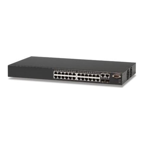
- Page 1 Powered by Accton ES3628C 24 10/100 Ports + 4GE Intelligent Layer 2/3/4 Fast Ethernet Switch Management Guide www.edge-core.com...
-
Page 3: Management Guide
Management Guide Fast Ethernet Switch Layer 3 Standalone Switch with 24 100BASE-TX (RJ-45) Ports, 2 1000BASE-T (RJ-45) Ports, and 2 SFP Slots... - Page 4 ES3628C F3.1.0.18 E032005-R01 149100005100H...
-
Page 5: Table Of Contents
Contents Chapter 1: Introduction Key Features Description of Software Features System Defaults Chapter 2: Initial Configuration Connecting to the Switch Configuration Options Required Connections Remote Connections Basic Configuration Console Connection Setting Passwords Setting an IP Address Manual Configuration Dynamic Configuration Enabling SNMP Management Access Community Strings (for SNMP version 1 and 2c clients) Trap Receivers... - Page 6 Contents Saving or Restoring Configuration Settings Downloading Configuration Settings from a Server Console Port Settings Telnet Settings Configuring Event Logging System Log Configuration Remote Log Configuration Displaying Log Messages Sending Simple Mail Transfer Protocol Alerts Resetting the System Setting the System Clock Configuring SNTP Setting the Time Zone Simple Network Management Protocol...
- Page 7 Configuring ACL Masks Specifying the Mask Type Configuring an IP ACL Mask Configuring a MAC ACL Mask Binding a Port to an Access Control List Port Configuration Displaying Connection Status Configuring Interface Connections Creating Trunk Groups Statically Configuring a Trunk Enabling LACP on Selected Ports Configuring LACP Parameters Displaying LACP Port Counters...
- Page 8 Contents Mapping Protocols to VLANs Class of Service Configuration Layer 2 Queue Settings Setting the Default Priority for Interfaces Mapping CoS Values to Egress Queues Selecting the Queue Mode Setting the Service Weight for Traffic Classes Layer 3/4 Priority Settings Mapping Layer 3/4 Priorities to CoS Values Selecting IP Precedence/DSCP Priority Mapping IP Precedence...
- Page 9 IP Routing Overview Initial Configuration IP Switching Routing Path Management Routing Protocols Basic IP Interface Configuration Configuring IP Routing Interfaces Address Resolution Protocol Proxy ARP Basic ARP Configuration Configuring Static ARP Addresses Displaying Dynamically Learned ARP Entries Displaying Local ARP Entries Displaying ARP Statistics Displaying Statistics for IP Protocols IP Statistics...
- Page 10 Contents Configuring DVMRP Interface Settings Displaying Neighbor Information Displaying the Routing Table Configuring PIM-DM Configuring Global PIM-DM Settings Configuring PIM-DM Interface Settings Displaying Interface Information Displaying Neighbor Information Chapter 4: Command Line Interface Using the Command Line Interface Accessing the CLI Console Connection Telnet Connection Entering Commands...
- Page 11 disable configure show history reload exit quit System Management Commands Device Designation Commands prompt hostname User Access Commands username enable password IP Filter Commands management show management Web Server Commands ip http port ip http server ip http secure-server ip http secure-port Telnet Server Commands ip telnet server Secure Shell Commands...
- Page 12 Contents SMTP Alert Commands logging sendmail host logging sendmail level logging sendmail source-email logging sendmail destination-email logging sendmail show logging sendmail Time Commands sntp client sntp server sntp poll show sntp clock timezone calendar set show calendar System Status Commands show startup-config show running-config show system...
- Page 13 Port Security Commands port security 802.1X Port Authentication dot1x system-auth-control dot1x default dot1x max-req dot1x port-control dot1x operation-mode dot1x re-authenticate dot1x re-authentication dot1x timeout quiet-period dot1x timeout re-authperiod dot1x timeout tx-period show dot1x Access Control List Commands IP ACLs access-list ip permit, deny (Standard ACL) permit, deny (Extended ACL) show ip access-list...
- Page 14 Contents snmp-server engine-id show snmp engine-id snmp-server view show snmp view snmp-server group show snmp group snmp-server user show snmp user DHCP Commands DHCP Client ip dhcp client-identifier ip dhcp restart client DHCP Relay ip dhcp restart relay ip dhcp relay server DHCP Server service dhcp ip dhcp excluded-address...
- Page 15 Interface Commands interface description speed-duplex negotiation capabilities shutdown switchport broadcast packet-rate clear counters show interfaces status show interfaces counters show interfaces switchport Mirror Port Commands port monitor show port monitor Rate Limit Commands rate-limit Link Aggregation Commands channel-group lacp lacp system-priority lacp admin-key (Ethernet Interface) lacp admin-key (Port Channel) lacp port-priority...
- Page 16 Contents max-hops spanning-tree spanning-disabled spanning-tree cost spanning-tree port-priority spanning-tree edge-port spanning-tree portfast spanning-tree link-type spanning-tree mst cost spanning-tree mst port-priority spanning-tree protocol-migration show spanning-tree show spanning-tree mst configuration VLAN Commands Editing VLAN Groups vlan database vlan Configuring VLAN Interfaces interface vlan switchport mode switchport acceptable-frame-types switchport ingress-filtering...
- Page 17 queue bandwidth queue cos-map show queue mode show queue bandwidth show queue cos-map Priority Commands (Layer 3 and 4) map ip port (Global Configuration) map ip port (Interface Configuration) map ip precedence (Global Configuration) map ip precedence (Interface Configuration) map ip dscp (Global Configuration) map ip dscp (Interface Configuration) show map ip port show map ip precedence...
- Page 18 Contents ip igmp query-interval ip igmp max-resp-interval ip igmp last-memb-query-interval ip igmp version show ip igmp interface clear ip igmp group show ip igmp groups IP Interface Commands Basic IP Configuration ip address ip default-gateway show ip interface show ip redirects ping Address Resolution Protocol (ARP) arp-timeout...
- Page 19 default-information originate timers spf area range area default-cost summary-address redistribute network area area stub area nssa area virtual-link ip ospf authentication ip ospf authentication-key ip ospf message-digest-key ip ospf cost ip ospf dead-interval ip ospf hello-interval ip ospf priority ip ospf retransmit-interval ip ospf transmit-delay show ip ospf show ip ospf border-routers...
- Page 20 Contents show ip dvmrp route show ip dvmrp neighbor show ip dvmrp interface PIM-DM Multicast Routing Commands router pim ip pim dense-mode ip pim hello-interval ip pim hello-holdtime ip pim trigger-hello-interval ip pim join-prune-holdtime ip pim graft-retry-interval ip pim max-graft-retries show router pim show ip pim interface show ip pim neighbor...
- Page 21 Tables Table 1-1 Key Features Table 1-2 System Defaults Table 3-1 Web Page Configuration Buttons Table 3-2 Switch Main Menu Table 3-3 Logging Levels Table 3-4 SNMPv3 Security Models and Levels Table 3-5 Supported Notification Messages Table 3-6 HTTPS System Support Table 3-7 802.1X Statistics Table 3-8...
- Page 22 Tables Table 4-18 Logging Levels Table 4-19 show logging flash/ram - display description Table 4-20 show logging trap - display description Table 4-21 SMTP Alert Commands Table 4-22 Time Commands Table 4-23 System Status Commands Table 4-24 Frame Size Commands Table 4-25 Flash/File Commands Table 4-26...
- Page 23 Table 4-63 Private VLAN Commands Table 4-64 Protocol-based VLAN Commands Table 4-65 GVRP and Bridge Extension Commands Table 4-66 Priority Commands Table 4-67 Priority Commands (Layer 2) Table 4-68 Default CoS Priority Levels Table 4-69 Priority Commands (Layer 3 and 4) Table 4-70 Mapping IP Precedence to CoS Values Table 4-71...
- Page 24 Tables Table 4-108 show ip dvmrp neighbor - display description Table 4-109 PIM-DM Multicast Routing Commands Table 4-110 show ip pim neighbor - display description Table 4-111 Router Redundancy Commands Table 4-112 VRRP Commands Table 4-113 show vrrp - display description Table 4-114 show vrrp brief - display description Table B-1...
- Page 25 Figures Figure 3-1 Home Page Figure 3-2 Front Panel Indicators Figure 3-3 System Information Figure 3-4 Switch Information Figure 3-5 Displaying Bridge Extension Configuration Figure 3-6 Configuring Support for Jumbo Frames Figure 3-7 IP Interface Configuration - Manual Figure 3-8 Default Gateway Figure 3-9 IP Interface Configuration - DHCP...
- Page 26 Figures Figure 3-42 802.1X Port Statistics Figure 3-43 IP Filter Figure 3-44 Selecting ACL Type Figure 3-45 ACL Configuration - Standard IP Figure 3-46 ACL Configuration - Extended IP Figure 3-47 ACL Configuration - MAC Figure 3-48 Selecting ACL Mask Types Figure 3-49 ACL Mask Configuration - IP Figure 3-50...
- Page 27 Figure 3-87 Queue Mode Figure 3-88 Queue Scheduling Figure 3-89 IP Precedence/DSCP Priority Status Figure 3-90 IP Precedence Priority Figure 3-91 IP DSCP Priority Figure 3-92 IP Port Priority Status Figure 3-93 IP Port Priority Figure 3-94 Configuring Class Maps Figure 3-95 Configuring Policy Maps Figure 3-96...
- Page 28 Figures Figure 3-132 RIP Interface Settings Figure 3-133 RIP Statistics Figure 3-134 OSPF General Configuration Figure 3-135 OSPF Area Configuration Figure 3-136 OSPF Range Configuration Figure 3-137 OSPF Interface Configuration Figure 3-138 OSPF Interface Configuration - Detailed Figure 3-139 OSPF Virtual Link Configuration Figure 3-140 OSPF Network Area Address Configuration Figure 3-141 OSPF Summary Address Configuration Figure 3-142 OSPF Redistribute Configuration...
-
Page 29: Chapter 1: Introduction
Chapter 1: Introduction This switch provides a broad range of features for Layer 2 switching and Layer 3 routing. It includes a management agent that allows you to configure the features listed in this manual. The default configuration can be used for most of the features provided by this switch. -
Page 30: Description Of Software Features
Introduction Feature Description Traffic Prioritization Default port priority, traffic class map, queue scheduling, IP Precedence, or Differentiated Services Code Point (DSCP), and TCP/UDP Port Qualify of Service Supports Differentiated Services (DiffServ) Router Redundancy Router backup is provided with the Virtual Router Redundancy Protocol (VRRP) IP Routing Routing Information Protocol (RIP), Open Shortest Path First (OSPF), static routes Static and dynamic address configuration, proxy ARP... - Page 31 Description of Software Features Access Control Lists – ACLs provide packet filtering for IP frames (based on address, protocol, TCP/UDP port number or TCP control code) or any frames (based on MAC address or Ethernet type). ACLs can by used to improve performance by blocking unnecessary network traffic or to implement security controls by restricting access to specific network resources or protocols.
- Page 32 Introduction IEEE 802.1D Bridge – The switch supports IEEE 802.1D transparent bridging. The address table facilitates data switching by learning addresses, and then filtering or forwarding traffic based on this information. The address table supports up to 16K addresses. Store-and-Forward Switching – The switch copies each frame into its memory before forwarding them to another port.
- Page 33 • Use private VLANs to restrict traffic to pass only between data ports and the uplink ports, thereby isolating adjacent ports within the same VLAN, and allowing you to limit the total number of VLANs that need to be configured. •...
- Page 34 Introduction remote network, the switch checks to see if it has the best route. If it does, it sends its own MAC address to the host. The host then sends traffic for the remote destination via the switch, which uses its own routing table to reach the destination on the other network.
-
Page 35: System Defaults
System Defaults The switch’s system defaults are provided in the configuration file “Factory_Default_Config.cfg.” To reset the switch defaults, this file should be set as the startup configuration file (page 3-24). The following table lists some of the basic system defaults. Function Parameter Console Port... - Page 36 Introduction Table 1-2 System Defaults (Continued) Function Parameter SNMP SNMP Agent Community Strings Traps SNMP V3 Port Configuration Admin Status Auto-negotiation Flow Control Rate Limiting Input and output limits Port Trunking Static Trunks LACP (all ports) Broadcast Storm Status Protection Broadcast Limit Rate Spanning Tree Status...
- Page 37 Table 1-2 System Defaults (Continued) Function Parameter IP Settings Management. VLAN IP Address Subnet Mask Default Gateway DHCP BOOTP Unicast Routing OSPF Router Redundancy VRRP Multicast Filtering IGMP Snooping (Layer 2) IGMP (Layer 3) Multicast Routing DVMRP PIM-DM System Log Status Messages Logged Messages Logged to Flash...
- Page 38 Introduction 1-10...
-
Page 39: Chapter 2: Initial Configuration
Chapter 2: Initial Configuration Connecting to the Switch Configuration Options The switch includes a built-in network management agent. The agent offers a variety of management options, including SNMP, RMON and a web-based interface. A PC may also be connected directly to the switch for configuration and monitoring via a command line interface (CLI). -
Page 40: Required Connections
Initial Configuration • Configure Spanning Tree parameters • Configure Class of Service (CoS) priority queuing • Configure up to 12 static or LACP trunks • Enable port mirroring • Set broadcast storm control on any port • Display system information and statistics Required Connections The switch provides an RS-232 serial port that enables a connection to a PC or terminal for monitoring and configuring the switch. -
Page 41: Remote Connections
Remote Connections Prior to accessing the switch’s onboard agent via a network connection, you must first configure it with a valid IP address, subnet mask, and default gateway using a console connection, DHCP or BOOTP protocol. The IP address for this switch is obtained via DHCP by default. To manually configure this address or enable dynamic address assignment via DHCP or BOOTP, see “Setting an IP Address”... -
Page 42: Setting Passwords
Type “username admin password 0 password,” for the Privileged Exec level, where password is your new password. Press <Enter>. Username: admin Password: CLI session with ES3628C Intelligent Standalone Switch is opened. To end the CLI session, enter [Exit]. Console#configure Console(config)#username guest password 0 [password]... -
Page 43: Dynamic Configuration
Before you can assign an IP address to the switch, you must obtain the following information from your network administrator: • IP address for the switch • Default gateway for the network • Network mask for this network To assign an IP address to the switch, complete the following steps: From the Privileged Exec level global configuration mode prompt, type “interface vlan 1”... -
Page 44: Enabling Snmp Management Access
Initial Configuration Wait a few minutes, and then check the IP configuration settings by typing the “show ip interface” command. Press <Enter>. Then save your configuration changes by typing “copy running-config startup-config.” Enter the startup file name and press <Enter>. Console(config)#interface vlan 1 Console(config-if)#ip address dhcp Console(config-if)#end... -
Page 45: Trap Receivers
The default strings are: • public - with read-only access. Authorized management stations are only able to retrieve MIB objects. • private - with read-write access. Authorized management stations are able to both retrieve and modify MIB objects. To prevent unauthorized access to the switch from SNMP version 1 or 2c clients, it is recommended that you change the default community strings. -
Page 46: Configuring Access For Snmp Version 3 Clients
Initial Configuration Configuring Access for SNMP Version 3 Clients To configure management access for SNMPv3 clients, you need to first create a view that defines the portions of MIB that the client can read or write, assign the view to a group, and then assign the user to a group. The following example creates one view called “mib-2”... -
Page 47: Managing System Files
Managing System Files The switch’s flash memory supports three types of system files that can be managed by the CLI program, web interface, or SNMP. The switch’s file system allows files to be uploaded and downloaded, copied, deleted, and set as a start-up file. The three types of files are: •... - Page 48 Initial Configuration 2-10...
-
Page 49: Chapter 3: Configuring The Switch
Chapter 3: Configuring the Switch Using the Web Interface This switch provides an embedded HTTP web agent. Using a web browser you can configure the switch and view statistics to monitor network activity. The web agent can be accessed by any computer on the network using a standard web browser (Internet Explorer 5.0 or above, or Netscape Navigator 6.2 or above). -
Page 50: Navigating The Web Browser Interface
Configuring the Switch Navigating the Web Browser Interface To access the web-browser interface you must first enter a user name and password. The administrator has Read/Write access to all configuration parameters and statistics. The default user name and password “admin” is used for the administrator. -
Page 51: Configuration Options
Configuration Options Configurable parameters have a dialog box or a drop-down list. Once a configuration change has been made on a page, be sure to click on the Apply button to confirm the new setting. The following table summarizes the web page configuration buttons. -
Page 52: Switch Main Menu
Configuring the Switch Main Menu Using the onboard web agent, you can define system parameters, manage and control the switch, and all its ports, or monitor network conditions. The following table briefly describes the selections available from this program. Menu System System Information Switch Information... -
Page 53: Table
Table 3-2 Switch Main Menu (Continued) Menu SNMPv3 Engine ID Remote Engine ID Users Remote Users Groups Views Security User Accounts Authentication Settings HTTPS Settings Settings Host-Key Settings Port Security 802.1X Information Configuration Port Configuration Statistics Configuration Mask Configuration Port Binding IP Filter Port Port Information... -
Page 54: Table
Configuring the Switch Table 3-2 Switch Main Menu (Continued) Menu LACP Configuration Aggregation Port Port Counters Information Port Internal Information Port Neighbors Information Displays settings and operational state for the remote side Port Broadcast Control Trunk Broadcast Control Mirror Port Configuration Rate Limit Input Port Configuration Input Trunk Configuration... -
Page 55: Table
Table 3-2 Switch Main Menu (Continued) Menu Trunk Configuration VLAN 802.1Q VLAN GVRP Status Basic Information Current Table Static List Static Table Static Membership by Port Configures membership type for interfaces, including tagged, Port Configuration Trunk Configuration Private VLAN Status Link Status Protocol VLAN Configuration... -
Page 56: Table
Configuring the Switch Table 3-2 Switch Main Menu (Continued) Menu DiffServ Class Map Policy Map Service Policy IGMP Snooping IGMP Configuration Multicast Router Port Information Static Multicast Router Port Configuration IP Multicast Registration Table IGMP Member Port Table General Configuration Static Host Table Cache DHCP... -
Page 57: Table
Table 3-2 Switch Main Menu (Continued) Menu General Static Addresses Dynamic Addresses Other Addresses Statistics IGMP Interface Settings Group Membership Statistics ICMP Routing Static Routes Routing Table Multicast Routing General Settings Multicast Routing Table VRRP Group Configuration Global Statistics Group Statistics Navigating the Web Browser Interface Description Sets the protocol timeout, and enables or disables proxy ARP for... -
Page 58: Table
Configuring the Switch Table 3-2 Switch Main Menu (Continued) Menu Routing Protocol General Settings Network Addresses Interface Settings Statistics OSPF General Configuration Area Configuration Area Range Configuration Interface Configuration Virtual Link Configuration Network Area Address Configuration Summary Address Configuration Redistribute Configuration NSSA Settings Link State Database Information... -
Page 59: Table
Table 3-2 Switch Main Menu (Continued) Menu PIM-DM General Settings Interface Settings Interface Information Neighbor Information Navigating the Web Browser Interface Description Enables or disables PIM-DM globally for the switch Enables or disables PIM-DM per interface, configures protocol settings for hello, prune and graft messages Displays summary information for each interface Displays neighboring PIM-DM routers Page... -
Page 60: Basic Configuration
Configuring the Switch Basic Configuration Displaying System Information You can easily identify the system by displaying the device name, location and contact information. Field Attributes • System Name – Name assigned to the switch system. • Object ID – MIB II object ID for switch’s network management subsystem. •... -
Page 61: Displaying Switch Hardware/Software Versions
CLI – Specify the hostname, location and contact information. Console(config)#hostname R&D 5 Console(config)#snmp-server location WC 9 Console(config)#snmp-server contact Ted Console(config)#exit Console#show system System description: 24/48 L3 GE Switch System OID String: 1.3.6.1.4.1.259.6.10.75 System information System Up Time: System Name: System Location: System Contact: MAC Address (unit1): Web Server:... -
Page 62: Switch Information
Configuring the Switch • Operation Code Version – Version number of runtime code. • Role – Shows that this switch is operating as Master or Slave These additional parameters are displayed for the CLI. • Unit ID – Unit number in stack •... -
Page 63: Displaying Bridge Extension Configuration
Displaying Bridge Extension Capabilities The Bridge MIB includes extensions for managed devices that support Multicast Filtering, Traffic Classes, and Virtual LANs. You can access these extensions to display default settings for the key variables. Field Attributes • Extended Multicast Filtering Services – This switch does not support the filtering of individual multicast addresses based on GMRP (GARP Multicast Registration Protocol). -
Page 64: Configuring Support For Jumbo Frames
Configuring the Switch CLI – Enter the following command. Console#show bridge-ext Max support VLAN numbers: Max support VLAN ID: Extended multicast filtering services: No Static entry individual port: VLAN learning: Configurable PVID tagging: Local VLAN capable: Traffic classes: Global GVRP status: GMRP: Console# Configuring Support for Jumbo Frames... -
Page 65: Figure
Setting the Switch’s IP Address This section describes how to configure an initial IP interface for management access over the network. The IP address for this switch is obtained via DHCP by default. To manually configure an address, you need to change the switch’s default settings to values that are compatible with your network. -
Page 66: Figure
Configuring the Switch Manual Configuration Web – Click IP, General, Routing Interface. Select the VLAN through which the management station is attached, set the IP Address Mode to “Static,” and specify a “Primary” interface. Enter the IP address, subnet mask and gateway, then click Apply. -
Page 67: Figure
Using DHCP/BOOTP If your network provides DHCP/BOOTP services, you can configure the switch to be dynamically configured by these services. Web – Click IP, General, Routing Interface. Specify the VLAN to which the management station is attached, set the IP Address Mode to DHCP or BOOTP. Click Apply to save your changes. -
Page 68: Managing Firmware
Configuring the Switch Renewing DCHP – DHCP may lease addresses to clients indefinitely or for a specific period of time. If the address expires or the network segment, you will lose management access to the switch. In this case, you can reboot the switch or submit a client request to restart DHCP service via the CLI. -
Page 69: Figure
Basic Configuration Downloading System Software from a Server When downloading runtime code, you can specify the destination file name to replace the current image, or first download the file using a different name from the current runtime code file, and then set the new file as the startup file. Web –... -
Page 70: Figure
Configuring the Switch To delete a file select System, File Management, Delete. Select the file name from the given list by checking the tick box and click Apply. Note that the file currently designated as the startup code cannot be deleted. CLI –... -
Page 71: Saving Or Restoring Configuration Settings
Saving or Restoring Configuration Settings You can upload/download configuration settings to/from a TFTP server, or copy files to and from switch units in a stack to restore the switch’s settings. Command Attributes • File Transfer Method – The configuration copy operation includes these options: - file to file –... -
Page 72: Figure
Configuring the Switch Downloading Configuration Settings from a Server You can download the configuration file under a new file name and then set it as the startup file, or you can specify the current startup configuration file as the destination file to directly replace it. -
Page 73: Figure
CLI – Enter the IP address of the TFTP server, specify the source file on the server, set the startup file name on the switch, and then restart the switch. Console#copy tftp startup-config TFTP server ip address: 192.168.1.19 Source configuration file name: config-1 Startup configuration file name [] : startup \Write to FLASH Programming. -
Page 74: Configuring The Console Port
Configuring the Switch • Speed – Sets the terminal line’s baud rate for transmit (to terminal) and receive (from terminal). Set the speed to match the baud rate of the device connected to the serial port. (Range: 9600, 19200, 38400, 57600, or 115200 baud, Auto; Default: Auto) •... -
Page 75: Telnet Settings
CLI – Enter Line Configuration mode for the console, then specify the connection parameters as required. To display the current console port settings, use the show line command from the Normal Exec level. Console(config)#line console Console(config-line)#login local Console(config-line)#password 0 secret Console(config-line)#timeout login response 0 Console(config-line)#exec-timeout 0 Console(config-line)#password-thresh 5... -
Page 76: Configuring The Telnet Interface
Configuring the Switch • Password – Specifies a password for the line connection. When a connection is started on a line with password protection, the system prompts for the password. If you enter the correct password, the system shows a prompt. (Default: No password) •... -
Page 77: Logging Levels
Configuring Event Logging The switch allows you to control the logging of error messages, including the type of events that are recorded in switch memory, logging to a remote System Log (syslog) server, and displays a list of recent event messages. System Log Configuration The system allows you to enable or disable event logging, and specify which levels are logged to RAM or flash memory. -
Page 78: Figure
Configuring the Switch Web – Click System, Logs, System Logs. Specify System Log Status, set the level of event messages to be logged to RAM and flash memory, then click Apply. CLI – Enable system logging and then specify the level of messages to be logged to RAM and flash memory. -
Page 79: Figure
Web – Click System, Logs, Remote Logs. To add an IP address to the Host IP List, type the new IP address in the Host IP Address box, and then click Add. To delete an IP address, click the entry in the Host IP List, and then click Remove. CLI –... -
Page 80: Figure
Configuring the Switch Displaying Log Messages Use the Logs page to scroll through the logged system and event messages. The switch can store up to 2048 log entries in temporary random access memory (RAM; i.e., memory flushed on power reset) and up to 4096 entries in permanent flash memory. -
Page 81: Enabling And Configuring Smtp Alerts
• SMTP Server List – Specifies a list of up to three recipient SMTP servers. The switch attempts to connect to the other listed servers if the first fails. Use the New SMTP Server text field and the Add/Remove buttons to configure the list. •... -
Page 82: Resetting The System
Configuring the Switch CLI – Enter the IP address of at least one SMTP server, set the syslog severity level to trigger an email message, and specify the switch (source) and up to five recipient (destination) email addresses. Enable SMTP with the logging sendmail command to complete the configuration. -
Page 83: Setting The System Clock
Setting the System Clock Simple Network Time Protocol (SNTP) allows the switch to set its internal clock based on periodic updates from a time server (SNTP or NTP). Maintaining an accurate time on the switch enables the system log to record meaningful dates and times for event entries. -
Page 84: Setting The Time Zone
Configuring the Switch CLI – This example configures the switch to operate as an SNTP client and then displays the current time and settings. Console(config)#sntp client Console(config)#sntp poll 16 Console(config)#sntp server 10.1.0.19 137.82.140.80 128.250.36.2 Console(config)#exit Console#show sntp Current time: 6 14:56:05 2004 Poll interval: 60 Current mode:... -
Page 85: Simple Network Management Protocol
Simple Network Management Protocol Simple Network Management Protocol Simple Network Management Protocol (SNMP) is a communication protocol designed specifically for managing devices on a network. Equipment commonly managed with SNMP includes switches, routers and host computers. SNMP is typically used to configure these devices for proper operation in a network environment, as well as to monitor them to evaluate performance or detect potential problems. -
Page 86: Enabling The Snmp Agent
Configuring the Switch security models v1 and v2c. The following table shows the security models and levels available and the system default settings. Table 3-4 SNMPv3 Security Models and Levels Model Level Group noAuthNoPriv public (read only) noAuthNoPriv private (read/write) noAuthNoPriv user defined user defined user defined user defined Community string only noAuthNoPriv public (read only) -
Page 87: Setting Community Access Strings
CLI – The following example enables SNMP on the switch. Console(config)#snmp-server Console(config)# Setting Community Access Strings You may configure up to five community strings authorized for management access by clients using SNMP v1 and v2c. All community strings used for IP Trap Managers should be listed in this table. -
Page 88: Specifying Trap Managers And Trap Types
Configuring the Switch Specifying Trap Managers and Trap Types Traps indicating status changes are issued by the switch to specified trap managers. You must specify trap managers so that key events are reported by this switch to your management station (using network management platforms such as HP OpenView). - Page 89 Version 1 or 2c clients), or define a corresponding “User Name” in the SNMPv3 Users page (for Version 3 clients). (Range: 1-32 characters, case sensitive) • Trap UDP Port – Specifies the UDP port number used by the trap manager. •...
-
Page 90: Configuring Snmpv3 Management Access
Configuring the Switch Web – Click SNMP, Configuration. Enter the IP address and community string for each management station that will receive trap messages, specify the UDP port, SNMP trap version, trap security level (for v3 clients), trap inform settings (for v2c/v3 clients), and then click Add. -
Page 91: Setting A Local Engine Id
Setting a Local Engine ID An SNMPv3 engine is an independent SNMP agent that resides on the switch. This engine protects against message replay, delay, and redirection. The engine ID is also used in combination with user passwords to generate the security keys for authenticating and encrypting SNMPv3 packets. -
Page 92: Configuring Snmpv3 Users
Configuring the Switch The engine ID can be specified by entering 1 to 26 hexadecimal characters. If less than 26 characters are specified, trailing zeroes are added to the value. For example, the value “1234” is equivalent to “1234” followed by 22 zeroes. Web –... -
Page 93: Configuring Snmpv3 Users
Simple Network Management Protocol • Privacy Protocol – The encryption algorithm use for data privacy; only 56-bit DES is currently available. • Privacy Password – A minimum of eight plain text characters is required. • Actions – Enables the user to be assigned to another SNMPv3 group. Web –... -
Page 94: Configuring Remote Snmpv3 Users
Configuring the Switch CLI – Use the snmp-server user command to configure a new user name and assign it to a group. Console(config)#snmp-server user chris group r&d v3 auth md5 greenpeace priv des56 einstien Console(config)#exit Console#show snmp user EngineId: 80000034030001f488f5200000 User Name: chris Authentication Protocol: md5 Privacy Protocol: des56... -
Page 95: Configuring Remote Snmpv3 Users
Simple Network Management Protocol • Privacy Protocol – The encryption algorithm use for data privacy; only 56-bit DES is currently available. • Privacy Password – A minimum of eight plain text characters is required. Web – Click SNMP, SNMPv3, Remote Users. Click New to configure a user name. In the New User page, define a name and assign it to a group, then click Add to save the configuration and return to the User Name list. -
Page 96: Configuring Snmpv3 Groups
Configuring the Switch CLI – Use the snmp-server user command to configure a new user name and assign it to a group. Console(config)#snmp-server user mark group r&d remote 192.168.1.19 v3 auth md5 greenpeace priv des56 einstien Console(config)#exit Console#show snmp user No user exist. -
Page 97: Supported Notification Messages
Table 3-5 Supported Notification Messages Object Label Object ID RFC 1493 Traps newRoot 1.3.6.1.2.1.17.0.1 topologyChange 1.3.6.1.2.1.17.0.2 SNMPv2 Traps coldStart 1.3.6.1.6.3.1.1.5.1 warmStart 1.3.6.1.6.3.1.1.5.2 1.3.6.1.6.3.1.1.5.3 linkDown 1.3.6.1.6.3.1.1.5.4 linkUp 1.3.6.1.6.3.1.1.5.5 authenticationFailure RMON Events (V2) risingAlarm 1.3.6.1.2.1.16.0.1 fallingAlarm 1.3.6.1.2.1.16.0.2 Simple Network Management Protocol Description The newRoot trap indicates that the sending agent has become the new root of the Spanning Tree;... - Page 98 Configuring the Switch Table 3-5 Supported Notification Messages (Continued) Object Label Object ID Private Traps swPowerStatus 1.3.6.1.4.1.259.6.10.75.2.1.0.1 ChangeTrap swFanFailureTrap 1.3.6.1.4.1.259.6.10.75.2.1.0.17 This trap is sent when the fan fails. swFanRecoverTrap 1.3.6.1.4.1.259.6.10.75.2.1.0.18 This trap is sent when the fan failure has swIpFilterRejectTrap 1.3.6.1.4.1.259.6.10.75.2.1.0.40 This trap is sent when an incorrect IP address is swSmtpConnFailure 1.3.6.1.4.1.259.6.10.75.2.1.0.41 This trap is triggered if the SMTP system cannot...
-
Page 99: Configuring Snmpv3 Groups
Web – Click SNMP, SNMPv3, Groups. Click New to configure a new group. In the New Group page, define a name, assign a security model and level, and then select read, write, and notify views. Click Add to save the new group and return to the Groups list. -
Page 100: Setting Snmpv3 Views
Configuring the Switch Setting SNMPv3 Views SNMPv3 views are used to restrict user access to specified portions of the MIB tree. The predefined view “defaultview” includes access to the entire MIB tree. Command Attributes • View Name – The name of the SNMP view. (Range: 1-64 characters) •... -
Page 101: User Authentication
CLI – Use the snmp-server view command to configure a new view. This example view includes the MIB-2 interfaces table, and the wildcard mask selects all index entries. Console(config)#snmp-server view ifEntry.a 1.3.6.1.2.1.2.2.1.1.* included Console(config)#exit Console#show snmp view View Name: ifEntry.a Subtree OID: 1.3.6.1.2.1.2.2.1.1.* View Type: included Storage Type: nonvolatile... -
Page 102: User Accounts
Configuring the Switch Command Attributes • Account List – Displays the current list of user accounts and associated access levels. (Defaults: admin, and guest) • New Account – Displays configuration settings for a new account. - User Name – The name of the user. (Maximum length: 8 characters;... -
Page 103: Configuring Local/Remote Logon Authentication
Configuring Local/Remote Logon Authentication Use the Authentication Settings menu to restrict management access based on specified user names and passwords. You can manually configure access rights on the switch, or you can use a remote access authentication server based on RADIUS or TACACS+ protocols. -
Page 104: Figure
Configuring the Switch • RADIUS Settings - Global – Provides globally applicable RADIUS settings. - ServerIndex – Specifies one of five RADIUS servers that may be configured. The switch attempts authentication using the listed sequence of servers. The process ends when a server either approves or denies access to a user. - Server IP Address –... -
Page 105: Authentication Server Settings
Web – Click Security, Authentication Settings. To configure local or remote authentication preferences, specify the authentication sequence (i.e., one to three methods), fill in the parameters for RADIUS or TACACS+ authentication if selected, and click Apply. Figure 3-34 Authentication Server Settings CLI –... -
Page 106: Https System Support
Configuring the Switch Console#config Console(config)#authentication login tacacs Console(config)#tacacs-server host 10.20.30.40 Console(config)#tacacs-server port 200 Console(config)#tacacs-server key green Console(config)#exit Console#show tacacs-server Server IP address: Communication key with tacacs server: ***** Server port number: Console(config)# Configuring HTTPS You can configure the switch to enable the Secure Hypertext Transfer Protocol (HTTPS) over the Secure Socket Layer (SSL), providing secure access (i.e., an encrypted connection) to the switch’s web interface. -
Page 107: Replacing The Default Secure-Site Certificate
Web – Click Security, HTTPS Settings. Enable HTTPS and specify the port number, then click Apply. CLI – This example enables the HTTP secure server and modifies the port number. Console(config)#ip http secure-server Console(config)#ip http secure-port 441 Console(config)# Replacing the Default Secure-site Certificate When you log onto the web interface using HTTPS (for secure access), a Secure Sockets Layer (SSL) certificate appears for the switch. -
Page 108: Configuring The Secure Shell
Configuring the Switch Configuring the Secure Shell The Berkley-standard includes remote access tools originally designed for Unix systems. Some of these tools have also been implemented for Microsoft Windows and other environments. These tools, including commands such as rlogin (remote login), rsh (remote shell), and rcp (remote copy), are not secure from hostile attacks. -
Page 109: Generating The Host Key Pair
be configured locally on the switch via the User Accounts page as described on page 3-53.) The clients are subsequently authenticated using these keys. The current firmware only accepts public key files based on standard UNIX format as shown in the following example for an RSA Version 1 key: 1024 35 1341081685609893921040944920155425347631641921872958921143173880 055536161631051775940838686311092912322268285192543746031009371877211996 963178136627741416898513204911720483033925432410163799759237144901193800... -
Page 110: Ssh Host-Key Settings
Configuring the Switch Field Attributes • Public-Key of Host-Key – The public key for the host. - RSA (Version 1): The first field indicates the size of the host key (e.g., 1024), the second field is the encoded public exponent (e.g., 65537), and the last string is the encoded modulus. -
Page 111: Configuring The Ssh Server
CLI – This example generates a host-key pair using both the RSA and DSA algorithms, stores the keys to flash memory, and then displays the host’s public keys. Console#ip ssh crypto host-key generate Console#ip ssh save host-key Console#show public-key host Host: RSA: 1024 65537 127250922544926402131336514546131189679055192360076028653006761... -
Page 112: Figure
Configuring the Switch Web – Click Security, SSH, Settings. Enable SSH and adjust the authentication parameters as required, then click Apply. Note that you must first generate the host key pair on the SSH Host-Key Settings page before you can enable the SSH server. CLI –... -
Page 113: Figure
Configuring Port Security Port security is a feature that allows you to configure a switch port with one or more device MAC addresses that are authorized to access the network through that port. When port security is enabled on a port, the switch stops learning new MAC addresses on the specified port when it has reached a configured maximum number. -
Page 114: Port Security
Configuring the Switch Web – Click Security, Port Security. Set the action to take when an invalid address is detected on a port, mark the checkbox in the Status column to enable security for a port, set the maximum number of MAC addresses allowed on a port, and click Apply. CLI –... -
Page 115: Figure
Configuring 802.1X Port Authentication Network switches can provide open and easy access to network resources by simply attaching a client PC. Although this automatic configuration and access is a desirable feature, it also allows unauthorized personnel to easily intrude and possibly gain access to sensitive network data. -
Page 116: Figure
Configuring the Switch • The RADIUS server and client also have to support the same EAP authentication type – MD5. (Some clients have native support in Windows, otherwise the dot1x client must support it.) Displaying 802.1X Global Settings The 802.1X protocol provides port authentication. Command Attributes 802.1X System Authentication Control –... -
Page 117: Figure
Configuring 802.1X Global Settings The 802.1X protocol provides port authentication. The 802.1X protocol must be enabled globally for the switch system before port settings are active. Command Attributes 802.1X System Authentication Control – Sets the global setting for 802.1X. (Default: Disabled) Web –... -
Page 118: Figure
Configuring the Switch • Max Request – Sets the maximum number of times the switch port will retransmit an EAP request packet to the client before it times out the authentication session. (Range: 1-10; Default 2) • Quiet Period – Sets the time that a switch port waits after the Max Request count has been exceeded before attempting to acquire a new client. - Page 119 CLI – This example sets the 802.1X parameters on port 2. For a description of the additional fields displayed in this example, see “show dot1x” on page 4-84. Console(config)#interface ethernet 1/2 Console(config-if)#dot1x port-control auto Console(config-if)#dot1x re-authentication Console(config-if)#dot1x max-req 5 Console(config-if)#dot1x timeout quiet-period 40 Console(config-if)#dot1x timeout re-authperiod 5 Console(config-if)#dot1x timeout tx-period 40 Console(config-if)#end...
-
Page 120: Displaying 802.1X Statistics
Configuring the Switch Displaying 802.1X Statistics This switch can display statistics for dot1x protocol exchanges for any port. Parameter Description Rx EAPOL Start The number of EAPOL Start frames that have been received by this Authenticator. Rx EAPOL Logoff The number of EAPOL Logoff frames that have been received by this Authenticator. Rx EAPOL Invalid The number of EAPOL frames that have been received by this Authenticator in which the frame type is not recognized. -
Page 121: Figure
Web – Select Security, 802.1X, Statistics. Select the required port and then click Query. Click Refresh to update the statistics. CLI – This example displays the dot1x statistics for port 4. Console#show dot1x statistics interface ethernet 1/4 Eth 1/4 Rx: EAPOL EAPOL Start Logoff... -
Page 122: Figure
Configuring the Switch Filtering IP Addresses for Management Access You can create a list of up to 16 IP addresses or IP address groups that are allowed management access to the switch through the web interface, SNMP, or Telnet. Command Usage •... -
Page 123: Figure
Web – Click Security, IP Filter. Enter the IP addresses or range of addresses that are allowed management access to an interface, and click Add IP Filtering Entry. CLI – This example restricts management access for Telnet clients. Console(config)#management telnet-client 192.168.1.19 Console(config)#management telnet-client 192.168.1.25 192.168.1.30 Console(config)#exit Console#show management all-client... -
Page 124: Figure
Configuring the Switch Access Control Lists Access Control Lists (ACL) provide packet filtering for IP frames (based on address, protocol, Layer 4 protocol port number or TCP control code) or any frames (based on MAC address or Ethernet type). To filter incoming packets, first create an access list, add the required rules, specify a mask to modify the precedence in which the rules are checked, and then bind the list to a specific port. -
Page 125: Figure
Setting the ACL Name and Type Use the ACL Configuration page to designate the name and type of an ACL. Command Attributes • Name – Name of the ACL. (Maximum length: 16 characters) • Type – There are three filtering modes: - Standard: IP ACL mode that filters packets based on the source IP address. -
Page 126: Figure
Configuring the Switch and compared with the address for each IP packet entering the port(s) to which this ACL has been assigned. Web – Specify the action (i.e., Permit or Deny). Select the address type (Any, Host, or IP). If you select “Host,” enter a specific address. If you select “IP,” enter a subnet address and the mask for an address range. - Page 127 • Protocol – Specifies the protocol type to match as TCP, UDP or Others, where others indicates a specific protocol number (0-255). (Options: TCP, UDP, Others; Default: TCP) • Source/Destination Port – Source/destination port number for the specified protocol type. (Range: 0-65535) •...
-
Page 128: Figure
Configuring the Switch Web – Specify the action (i.e., Permit or Deny). Specify the source and/or destination addresses. Select the address type (Any, Host, or IP). If you select “Host,” enter a specific address. If you select “IP,” enter a subnet address and the mask for an address range. -
Page 129: Configuring A Mac Acl
Configuring a MAC ACL Command Attributes • Action – An ACL can contain any combination of permit or deny rules. • Source/Destination Address Type – Use “Any” to include all possible addresses, “Host” to indicate a specific MAC address, or “MAC” to specify an address range with the Address and Bitmask fields. -
Page 130: Figure
Configuring the Switch Web – Specify the action (i.e., Permit or Deny). Specify the source and/or destination addresses. Select the address type (Any, Host, or MAC). If you select “Host,” enter a specific address (e.g., 11-22-33-44-55-66). If you select “MAC,” enter a base address and a hexidecimal bitmask for an address range. -
Page 131: Figure
Configuring ACL Masks You must specify masks that control the order in which ACL rules are checked. The switch includes two system default masks that pass/filter packets matching the permit/deny rules specified in an ingress ACL. You can also configure up to seven user-defined masks for an ingress or egress ACL. -
Page 132: Configuring An Ip Acl Mask
Configuring the Switch Configuring an IP ACL Mask This mask defines the fields to check in the IP header. Command Usage • Masks that include an entry for a Layer 4 protocol source port or destination port can only be applied to packets with a header length of exactly five bytes. Command Attributes •... -
Page 133: Figure
Web – Configure the mask to match the required rules in the IP ingress or egress ACLs. Set the mask to check for any source or destination address, a specific host address, or an address range. Include other criteria to search for in the rules, such as a protocol type or one of the service types. -
Page 134: Figure
Configuring the Switch Configuring a MAC ACL Mask This mask defines the fields to check in the packet header. Command Usage You must configure a mask for an ACL rule before you can bind it to a port. Command Attributes •... -
Page 135: Binding A Port To An Access Control List
CLI – This example shows how to create an Ingress MAC ACL and bind it to a port. You can then see that the order of the rules have been changed by the mask. Console(config)#access-list mac M4 Console(config-mac-acl)#permit any any Console(config-mac-acl)#deny tagged-eth2 00-11-11-11-11-11 ff-ff-ff-ff-ff-ff any vid 3 Console(config-mac-acl)#end... -
Page 136: Port Configuration
Configuring the Switch Web – Click Security, ACL, Port Binding. Mark the Enable field for the port you want to bind to an ACL for ingress or egress traffic, select the required ACL from the drop-down list, then click Apply. CLI –... -
Page 137: Port - Port Information
• Trunk Member – Shows if port is a trunk member. • Creation – Shows if a trunk is manually configured or dynamically set via LACP. Web – Click Port, Port Information or Trunk Information. Field Attributes (CLI) Basic information: •... -
Page 138: Current Status
Configuring the Switch • Flow control – Shows if flow control is enabled or disabled. • LACP – Shows if LACP is enabled or disabled. • Port security – Shows if port security is enabled or disabled. • Max MAC count – Shows the maximum number of MAC address that can be learned by a port. -
Page 139: Configuring Interface Connections
Configuring Interface Connections You can use the Port Configuration or Trunk Configuration page to enable/disable an interface, set auto-negotiation and the interface capabilities to advertise, or manually fix the speed and duplex mode, and flow control. Command Attributes • Name – Allows you to label an interface. (Range: 1-64 characters) •... -
Page 140: Port - Port Configuration
Configuring the Switch Web – Click Port, Port Configuration or Trunk Configuration. Modify the required interface settings, and click Apply. CLI – Select the interface, and then enter the required settings. Console(config)#interface ethernet 1/13 Console(config-if)#description RD SW#13 Console(config-if)#shutdown Console(config-if)#no shutdown Console(config-if)#no negotiation Console(config-if)#speed-duplex 100half Console(config-if)#negotiation... -
Page 141: Creating Trunk Groups
Creating Trunk Groups You can create multiple links between devices that work as one virtual, aggregate link. A port trunk offers a dramatic increase in bandwidth for network segments where bottlenecks exist, as well as providing a fault-tolerant link between two devices. -
Page 142: Statically Configuring A Trunk
Configuring the Switch Statically Configuring a Trunk Command Usage • When configuring static trunks, you may not be able to link switches of different types, depending on the manufacturer’s implementation. However, note that the static trunks on this switch are Cisco EtherChannel compatible. -
Page 143: Enabling Lacp On Selected Ports
CLI – This example creates trunk 1 with ports 9 and 10. Just connect these ports to two static trunk ports on another switch to form a trunk. Console(config)#interface port-channel 1 Console(config-if)#exit Console(config)#interface ethernet 1/9 Console(config-if)#channel-group 1 Console(config-if)#exit Console(config)#interface ethernet 1/10 Console(config-if)#channel-group 1 Console(config-if)#end Console#show interfaces status port-channel 1... -
Page 144: Lacp Trunk Configuration
Configuring the Switch Command Attributes • Member List (Current) – Shows configured trunks (Unit, Port). • New – Includes entry fields for creating new trunks. - Unit – Stack unit . (Range: 1-1) - Port – Port identifier. (Range: 1-28) Web –... - Page 145 CLI – The following example enables LACP for ports 1 to 6. Just connect these ports to LACP-enabled trunk ports on another switch to form a trunk. Console(config)#interface ethernet 1/1 Console(config-if)#lacp Console(config-if)#exit Console(config)#interface ethernet 1/6 Console(config-if)#lacp Console(config-if)#end Console#show interfaces status port-channel 1 Information of Trunk 1 Basic information: Port type:...
-
Page 146: Configuring Lacp Parameters
Configuring the Switch Configuring LACP Parameters Dynamically Creating a Port Channel – Ports assigned to a common port channel must meet the following criteria: • Ports must have the same LACP System Priority. • Ports must have the same LACP port Admin Key. •... -
Page 147: Lacp - Aggregation Port
Port Configuration Web – Click Port, LACP, Aggregation Port. Set the System Priority, Admin Key, and Port Priority for the Port Actor. You can optionally configure these settings for the Port Partner. (Be aware that these settings only affect the administrative state of the partner, and will not take effect until the next time an aggregate link is formed with this device.) After you have completed setting the port LACP parameters, click Apply. - Page 148 Configuring the Switch CLI – The following example configures LACP parameters for ports 1-10. Ports 1-8 are used as active members of the LAG, ports 9 and 10 are set to backup mode. Console(config)#interface ethernet 1/1 Console(config-if)#lacp actor system-priority 3 Console(config-if)#lacp actor admin-key 120 Console(config-if)#lacp actor port-priority 128 Console(config-if)#exit...
-
Page 149: Lacp - Port Counters Information
Displaying LACP Port Counters You can display statistics for LACP protocol messages. Parameter Description LACPDUs Sent Number of valid LACPDUs transmitted from this channel group. LACPDUs Received Number of valid LACPDUs received by this channel group. Marker Sent Number of valid Marker PDUs transmitted from this channel group. Marker Received Number of valid Marker PDUs received by this channel group. -
Page 150: Displaying Lacp Settings And Status For The Local Side
Configuring the Switch Displaying LACP Settings and Status for the Local Side You can display configuration settings and the operational state for the local side of an link aggregation. Table 3-9 LACP Internal Configuration Information Field Description Oper Key Current operational value of the key for the aggregation port. Admin Key Current administrative value of the key for the aggregation port. -
Page 151: Lacp - Port Internal Information
Web – Click Port, LACP, Port Internal Information. Select a port channel to display the corresponding information. Figure 3-58 LACP - Port Internal Information CLI – The following example displays the LACP configuration settings and operational state for the local side of port channel 1. Console#show lacp 1 internal Port channel: 1 -------------------------------------------------------------------------... -
Page 152: Displaying Lacp Settings And Status For The Remote Side
Configuring the Switch Displaying LACP Settings and Status for the Remote Side You can display configuration settings and the operational state for the remote side of an link aggregation. Table 3-10 LACP Neighbor Configuration Information Field Description Partner Admin System ID LAG partner’s system ID assigned by the user. -
Page 153: Setting Broadcast Storm Thresholds
CLI – The following example displays the LACP configuration settings and operational state for the remote side of port channel 1. Console#show lacp 1 neighbors Port channel 1 neighbors ------------------------------------------------------------------------- Eth 1/2 ------------------------------------------------------------------------- Partner Admin System ID: Partner Oper System ID: Partner Admin Port Number: 2 Partner Oper Port Number: Port Admin Priority:... -
Page 154: Port Broadcast Control
Configuring the Switch Web – Click Port, Port Broadcast Control or Trunk Broadcast Control. Check the Enabled box for any interface, set the threshold, and click Apply. CLI – Specify any interface, and then enter the threshold. The following disables broadcast storm control for port 1, and then sets broadcast suppression at 600 packets per second for port 2. -
Page 155: Configuring Port Mirroring
Configuring Port Mirroring You can mirror traffic from any source port to a target port for real-time analysis. You can then attach a logic analyzer or RMON probe to the target port and study the traffic crossing the source port in a completely unobtrusive manner. Command Usage •... -
Page 156: Configuring Rate Limits
Configuring the Switch Configuring Rate Limits This function allows the network manager to control the maximum rate for traffic transmitted or received on an interface. Rate limiting is configured on interfaces at the edge of a network to limit traffic into or out of the switch. Traffic that falls within the rate limit is transmitted, while packets that exceed the acceptable amount of traffic are dropped. -
Page 157: Showing Port Statistics
Showing Port Statistics You can display standard statistics on network traffic from the Interfaces Group and Ethernet-like MIBs, as well as a detailed breakdown of traffic based on the RMON MIB. Interfaces and Ethernet-like statistics display errors on the traffic passing through each port. - Page 158 Configuring the Switch Parameter Transmit Discarded Packets Transmit Errors Etherlike Statistics Alignment Errors Late Collisions FCS Errors Excessive Collisions Single Collision Frames Internal MAC Transmit Errors Multiple Collision Frames Carrier Sense Errors SQE Test Errors Frames Too Long Deferred Transmissions Internal MAC Receive Errors RMON Statistics Drop Events...
- Page 159 Table 3-11 Port Statistics (Continued) Parameter Received Frames Broadcast Frames Multicast Frames CRC/Alignment Errors Undersize Frames Oversize Frames Fragments 64 Bytes Frames 65-127 Byte Frames 128-255 Byte Frames 256-511 Byte Frames 512-1023 Byte Frames 1024-1518 Byte Frames 1519-1536 Byte Frames Description The total number of frames (bad, broadcast and multicast) received.
-
Page 160: Port Statistics
Configuring the Switch Web – Click Port, Port Statistics. Select the required interface, and click Query. You can also use the Refresh button at the bottom of the page to update the screen. Figure 3-63 Port Statistics 3-112... -
Page 161: Setting Static Addresses
CLI – This example shows statistics for port 12. Console#show interfaces counters ethernet 1/12 Ethernet 1/12 Iftable stats: Octets input: 868453, Octets output: 3492122 Unicast input: 7315, Unitcast output: 6658 Discard input: 0, Discard output: 0 Error input: 0, Error output: 0 Unknown protos input: 0, QLen output: 0 Extended iftable stats: Multi-cast input: 0, Multi-cast output: 17027... -
Page 162: Displaying The Address Table
Configuring the Switch Web – Click Address Table, Static Addresses. Specify the interface, the MAC address and VLAN, then click Add Static Address. CLI – This example adds an address to the static address table, but sets it to be deleted when the switch is reset. -
Page 163: Dynamic Addresses
Web – Click Address Table, Dynamic Addresses. Specify the search type (i.e., mark the Interface, MAC Address, or VLAN checkbox), select the method of sorting the displayed addresses, and then click Query. CLI – This example also displays the address table entries for port 1. Console#show mac-address-table interface ethernet 1/1 Interface Mac Address --------- ----------------- ---- -----------------... -
Page 164: Changing The Aging Time
Configuring the Switch Changing the Aging Time You can set the aging time for entries in the dynamic address table. Command Attributes • Aging Status – Enables/disables the aging function. • Aging Time – The time after which a learned entry is discarded. (Range: 10-1000000 seconds;... -
Page 165: Displaying Global Settings
Designated Root Once a stable network topology has been established, all bridges listen for Hello BPDUs (Bridge Protocol Data Units) transmitted from the Root Bridge. If a bridge does not get a Hello BPDU after a predefined interval (Maximum Age), the bridge assumes that the link to the Root Bridge is down. - Page 166 Configuring the Switch new root port is selected from among the device ports attached to the network. (References to “ports” in this section mean “interfaces,” which includes both ports and trunks.) • Hello Time – Interval (in seconds) at which the root device transmits a configuration message.
-
Page 167: Sta Information
• Root Forward Delay – The maximum time (in seconds) this device will wait before changing states (i.e., discarding to learning to forwarding). This delay is required because every device must receive information about topology changes before it starts to forward frames. In addition, each port needs time to listen for conflicting information that would make it return to a discarding state;... -
Page 168: Configuring Global Settings
Configuring the Switch Transmission limit: Path Cost Method: --------------------------------------------------------------- 1/ 1 information --------------------------------------------------------------- Admin status: Role: State: External admin path cost: 10000 Internal admin cost: External oper path cost: Internal oper path cost: Priority: Designated cost: Designated port: Designated root: Designated bridge: Fast forwarding: Forward transitions:... - Page 169 • Multiple Spanning Tree Protocol - To allow multiple spanning trees to operate over the network, you must configure a related set of bridges with the same MSTP configuration, allowing them to participate in a specific set of spanning tree instances. - A spanning tree instance can exist only on bridges that have compatible VLAN instance assignments.
- Page 170 Configuring the Switch • Forward Delay – The maximum time (in seconds) this device will wait before changing states (i.e., discarding to learning to forwarding). This delay is required because every device must receive information about topology changes before it starts to forward frames.
-
Page 171: Sta Global Configuration
Spanning Tree Algorithm Configuration Web – Click Spanning Tree, STA, Configuration. Modify the required attributes, and click Apply. Figure 3-68 STA Global Configuration 3-123... -
Page 172: Displaying Interface Settings
Configuring the Switch CLI – This example enables Spanning Tree Protocol, sets the mode to MST, and then configures the STA and MSTP parameters. Console(config)#spanning-tree Console(config)#spanning-tree mode mstp Console(config)#spanning-tree priority 40000 Console(config)#spanning-tree hello-time 5 Console(config)#spanning-tree max-age 38 Console(config)#spanning-tree forward-time 20 Console(config)#spanning-tree pathcost method long Console(config)#spanning-tree transmission-limit 4 Console(config)#Console(config)#spanning-tree mst-configuration... - Page 173 • Oper Path Cost – The contribution of this port to the path cost of paths towards the spanning tree root which include this port. • Oper Link Type – The operational point-to-point status of the LAN segment attached to this interface. This parameter is determined by manual configuration or by auto-detection, as described for Admin Link Type in STA Port Configuration on page 3-127.
-
Page 174: Sta Port Information
Configuring the Switch • Internal path cost – The path cost for the MST. See the preceding item. • Priority – Defines the priority used for this port in the Spanning Tree Algorithm. If the path cost for all ports on a switch is the same, the port with the highest priority (i.e., lowest value) will be configured as an active link in the Spanning Tree. -
Page 175: Configuring Interface Settings
CLI – This example shows the STA attributes for port 5. Console#show spanning-tree ethernet 1/5 1/ 5 information -------------------------------------------------------------- Admin status: Role: State: External admin path cost: 10000 Internal admin cost: External oper path cost: Internal oper path cost: Priority: Designated cost: Designated port: Designated root:... - Page 176 Configuring the Switch The following interface attributes can be configured: • Spanning Tree – Enables/disables STA on this interface. (Default: Enabled) • Priority – Defines the priority used for this port in the Spanning Tree Protocol. If the path cost for all ports on a switch are the same, the port with the highest priority (i.e., lowest value) will be configured as an active link in the Spanning Tree.
-
Page 177: Configuring Multiple Spanning Trees
Migration button to manually re-check the appropriate BPDU format (RSTP or STP-compatible) to send on the selected interfaces. (Default: Disabled) Web – Click Spanning Tree, STA, Port Configuration or Trunk Configuration. Modify the required attributes, then click Apply. CLI – This example sets STA attributes for port 7. Console(config)#interface ethernet 1/7 Console(config-if)#no spanning-tree spanning-disabled Console(config-if)#spanning-tree port-priority 0... -
Page 178: Mstp Vlan Configuration
Configuring the Switch Note: All VLANs are automatically added to the IST (Instance 0). To ensure that the MSTI maintains connectivity across the network, you must configure a related set of bridges with the same MSTI settings. Command Attributes • MST Instance – Instance identifier of this spanning tree. (Default: 0) •... - Page 179 CLI – This displays STA settings for instance 1, followed by settings for each port. Console#show spanning-tree mst 1 Spanning-tree information --------------------------------------------------------------- Spanning tree mode: Spanning tree enabled/disabled: Instance: VLANs configuration: Priority: Bridge Hello Time (sec.): Bridge Max Age (sec.): Bridge Forward Delay (sec.): Root Hello Time (sec.): Root Max Age (sec.):...
-
Page 180: Displaying Interface Settings For Mstp
Configuring the Switch Displaying Interface Settings for MSTP The MSTP Port Information and MSTP Trunk Information pages display the current status of ports and trunks in the selected MST instance. Field Attributes MST Instance ID – Instance identifier to configure. (Range: 0-4094; Default: 0) The other attributes are described under “Displaying Interface Settings,”... -
Page 181: Configuring Interface Settings For Mstp
--------------------------------------------------------------- 1/ 1 information --------------------------------------------------------------- Admin status: Role: State: External admin path cost: 10000 Internal admin path cost: 10000 External oper path cost: Internal oper path cost: Priority: Designated cost: Designated port: Designated root: Designated bridge: Fast forwarding: Forward transitions: Admin edge port: Oper edge port: Admin Link type:... -
Page 182: Mstp Port Configuration
Configuring the Switch • Admin MST Path Cost – This parameter is used by the MSTP to determine the best path between devices. Therefore, lower values should be assigned to ports attached to faster media, and higher values assigned to ports with slower media. (Path cost takes precedence over port priority.) Note that when the Path Cost Method is set to short (page 3-63), the maximum path cost is 65,535. -
Page 183: Vlan Configuration
VLAN Configuration VLAN Configuration IEEE 802.1Q VLANs In large networks, routers are used to isolate broadcast traffic for each subnet into separate domains. This switch provides a similar service at Layer 2 by using VLANs to organize any group of network nodes into separate broadcast domains. VLANs confine broadcast traffic to the originating group, and can eliminate broadcast storms in large networks. - Page 184 Configuring the Switch Note: VLAN-tagged frames can pass through VLAN-aware or VLAN-unaware network interconnection devices, but the VLAN tags should be stripped off before passing it on to any end-node host that does not support VLAN tagging. tagged frames VLAN Classification – When the switch receives a frame, it classifies the frame in one of two ways.
-
Page 185: Forwarding Tagged/Untagged Frames
these hosts, and core switches in the network, enable GVRP on the links between these devices. You should also determine security boundaries in the network and disable GVRP on the boundary ports to prevent advertisements from being propagated, or forbid those ports from joining restricted VLANs. Note: If you have host devices that do not support GVRP, you should configure static or untagged VLANs for the switch ports connected to these devices (as described in... -
Page 186: Vlan Basic Information
Configuring the Switch Enabling or Disabling GVRP (Global Setting) GARP VLAN Registration Protocol (GVRP) defines a way for switches to exchange VLAN information in order to register VLAN members on ports across the network. VLANs are dynamically configured based on join messages issued by host devices and propagated throughout the network. -
Page 187: Displaying Current Vlans
CLI – Enter the following command. Console#show bridge-ext Max support VLAN numbers: Max support VLAN ID: Extended multicast filtering services: No Static entry individual port: VLAN learning: Configurable PVID tagging: Local VLAN capable: Traffic classes: Global GVRP status: GMRP: Console# Displaying Current VLANs The VLAN Current Table shows the current port members of each VLAN and whether or not the port supports VLAN tagging. -
Page 188: Creating Vlans
Configuring the Switch Command Attributes (CLI) • VLAN – ID of configured VLAN (1-4094, no leading zeroes). • Type – Shows how this VLAN was added to the switch. - Dynamic: Automatically learned via GVRP. - Static: Added as a static entry. •... -
Page 189: Adding Static Members To Vlans (Vlan Index)
Web – Click VLAN, 802.1Q VLAN, Static List. To create a new VLAN, enter the VLAN ID and VLAN name, mark the Enable checkbox to activate the VLAN, and then click Add. Figure 3-77 VLAN Static List - Creating VLANs CLI –... -
Page 190: Vlan Static Table - Adding Static Members
Configuring the Switch Command Attributes • VLAN – ID of configured VLAN (1-4094). • Name – Name of the VLAN (1 to 32 characters). • Status – Enables or disables the specified VLAN. - Enable: VLAN is operational. - Disable: VLAN is suspended; i.e., does not pass packets. •... -
Page 191: Adding Static Members To Vlans (Port Index)
CLI – The following example adds tagged and untagged ports to VLAN 2. Console(config)#interface ethernet 1/1 Console(config-if)#switchport allowed vlan add 2 tagged Console(config-if)#exit Console(config)#interface ethernet 1/2 Console(config-if)#switchport allowed vlan add 2 untagged Console(config-if)#exit Console(config)#interface ethernet 1/13 Console(config-if)#switchport allowed vlan add 2 tagged Console(config-if)# Adding Static Members to VLANs (Port Index) Use the VLAN Static Membership by Port menu to assign VLAN groups to the... -
Page 192: Configuring Vlan Behavior For Interfaces
Configuring the Switch Configuring VLAN Behavior for Interfaces You can configure VLAN behavior for specific interfaces, including the default VLAN identifier (PVID), accepted frame types, ingress filtering, GVRP status, and GARP timers. Command Usage • GVRP – GARP VLAN Registration Protocol defines a way for switches to exchange VLAN information in order to automatically register VLAN members on interfaces across the network. -
Page 193: Vlan Port Configuration
Leave or LeaveAll message has been issued, the applicants can rejoin before the port actually leaves the group. (Range: 60-3000 centiseconds; Default: 60) • GARP LeaveAll Timer message for VLAN group participants and the port leaving the group. This interval should be considerably larger than the Leave Time to minimize the amount of traffic generated by nodes rejoining the group. -
Page 194: Configuring Private Vlans
Configuring the Switch CLI – This example sets port 3 to accept only tagged frames, assigns PVID 3 as the native VLAN ID, enables GVRP, sets the GARP timers, and then sets the switchport mode to hybrid. Console(config)#interface ethernet 1/3 Console(config-if)#switchport acceptable-frame-types tagged Console(config-if)#switchport ingress-filtering Console(config-if)#switchport native vlan 3... -
Page 195: Configuring Uplink And Downlink Ports
Configuring Uplink and Downlink Ports Use the Private VLAN Link Status page to set ports as downlink or uplink ports. Ports designated as downlink ports can not communicate with any other ports on the switch except for the uplink ports. Uplink ports can communicate with any other ports on the switch and with any designated downlink ports. -
Page 196: Configuring Protocol Groups
Configuring the Switch Command Usage To configure protocol-based VLANs, follow these steps: 1. First configure VLAN groups for the protocols you want to use (page 3-140). Although not mandatory, we suggest configuring a separate VLAN for each major protocol running on your network. Do not add port members at this time. 2. -
Page 197: Mapping Protocols To Vlans
Mapping Protocols to VLANs Map a protocol group to a VLAN for each interface that will participate in the group. Command Usage • When creating a protocol-based VLAN, only assign interfaces using this configuration screen. If you assign interfaces using any of the other VLAN menus such as the VLAN Static Table (page 3-141) or VLAN Static Membership by Port menu (page 3-143), these interfaces will admit traffic of any protocol type into the associated VLAN. -
Page 198: Class Of Service Configuration
Configuring the Switch CLI – The following maps the traffic entering Port 1 which matches the protocol type specified in protocol group 1 to VLAN 3. Console(config)#interface ethernet 1/1 Console(config-if)#protocol-vlan protocol-group 1 vlan 3 Console(config-if)# Class of Service Configuration Class of Service (CoS) allows you to specify which data packets have greater precedence when traffic is buffered in the switch due to congestion. -
Page 199: Default Port Priority
Web – Click Priority, Default Port Priority or Default Trunk Priority. Modify the default priority for any interface, then click Apply. CLI – This example assigns a default priority of 5 to port 3. Console(config)#interface ethernet 1/3 Console(config-if)#switchport priority default 5 Console(config-if)#end Console#show interfaces switchport ethernet 1/5 Information of Eth 1/5... -
Page 200: Mapping Cos Values To Egress Queues
Configuring the Switch Mapping CoS Values to Egress Queues This switch processes Class of Service (CoS) priority tagged traffic by using eight priority queues for each port, with service schedules based on strict or Weighted Round Robin (WRR). Up to eight separate traffic priorities are defined in IEEE 802.1p. -
Page 201: Traffic Classes
Web – Click Priority, Traffic Classes. Assign priorities to the traffic classes (i.e., output queues), then click Apply. CLI – The following example shows how to change the CoS assignments to a one-to-one mapping. Console(config)#interface ethernet 1/1 Console(config)#queue cos-map 0 0 Console(config)#queue cos-map 1 1 Console(config)#queue cos-map 2 2 Console(config)#exit... -
Page 202: Figure 3-87 Queue Mode
Configuring the Switch Selecting the Queue Mode You can set the switch to service the queues based on a strict rule that requires all traffic in a higher priority queue to be processed before lower priority queues are serviced, or use Weighted Round-Robin (WRR) queuing that specifies a relative weight of each queue. -
Page 203: Figure 3-88 Queue Scheduling
Web – Click Priority, Queue Scheduling. Select the interface, highlight a traffic class (i.e., output queue), enter a weight, then click Apply. CLI – The following example shows how to assign WRR weights to each of the priority queues. Console(config)#queue bandwidth 1 3 5 7 9 11 13 15 Console(config)#exit Console#show queue bandwidth Information of Eth 1/1... -
Page 204: Figure 3-89 Ip Precedence/Dscp Priority Status
Configuring the Switch Layer 3/4 Priority Settings Mapping Layer 3/4 Priorities to CoS Values This switch supports several common methods of prioritizing layer 3/4 traffic to meet application requirements. Traffic priorities can be specified in the IP header of a frame, using the priority bits in the Type of Service (ToS) octet or the number of the TCP port. -
Page 205: Figure 3-90 Ip Precedence Priority
Mapping IP Precedence The Type of Service (ToS) octet in the IPv4 header includes three precedence bits defining eight different priority levels ranging from highest priority for network control packets to lowest priority for routine traffic. The default IP Precedence values are mapped one-to-one to Class of Service values (i.e., Precedence value 0 maps to CoS value 0, and so forth). -
Page 206: Mapping Dscp Priority
Configuring the Switch CLI – The following example globally enables IP Precedence service on the switch, maps IP Precedence value 1 to CoS value 0 (on port 1), and then displays the IP Precedence settings. Console(config)#map ip precedence Console(config)#interface ethernet 1/1 Console(config-if)#map ip precedence 1 cos 0 Console(config-if)#end Console#show map ip precedence ethernet 1/1... -
Page 207: Figure 3-91 Ip Dscp Priority
Web – Click Priority, IP DSCP Priority. Select an entry from the DSCP table, enter a value in the Class of Service Value field, then click Apply. CLI – The following example globally enables DSCP Priority service on the switch, maps DSCP value 0 to CoS value 1 (on port 1), and then displays the DSCP Priority settings. -
Page 208: Figure 3-92 Ip Port Priority Status
Configuring the Switch Mapping IP Port Priority You can also map network applications to Class of Service values based on the IP port number (i.e., TCP/UDP port number) in the frame header. Some of the more common TCP service ports include: HTTP: 80, FTP: 21, Telnet: 23 and POP3: 110. Command Attributes •... -
Page 209: Quality Of Service
CLI – The following example globally enables IP Port Priority service on the switch, maps HTTP traffic (on port 1) to CoS value 0, and then displays the IP Port Priority settings. Console(config)#map ip port Console(config)#interface ethernet 1/1 Console(config-if)#map ip port 80 cos 0 Console(config-if)#end Console#show map ip port ethernet 1/5 TCP port mapping status: disabled... -
Page 210: Configuring Quality Of Service Parameters
Configuring the Switch Configuring Quality of Service Parameters To create a service policy for a specific category or ingress traffic, follow these steps: 1. Use the “Class Map” to designate a class name for a specific category of traffic. 2. Edit the rules for each class to specify a type of traffic based on an access list, a DSCP or IP Precedence value, or a VLAN. - Page 211 Command Attributes Class Map • Modify Name and Description – Configures the name and a brief description of a class map. (Range: 1-32 characters for the name; 1-256 characters for the description) • Edit Rules – Opens the “Match Class Settings” page for the selected class entry. Modify the criteria used to classify ingress traffic on this page.
-
Page 212: Figure 3-94 Configuring Class Maps
Configuring the Switch Web – Click QoS, DiffServ, then click Add Class to create a new class, or Edit Rules to change the rules of an existing class. CLI - This example creates a class map call “rd-class,” and sets it to match packets marked for DSCP service value 3. -
Page 213: Creating Qos Policies
Creating QoS Policies This function creates a policy map that can be attached to multiple interfaces. Command Usage • To configure a Policy Map, follow these steps: - Create a Class Map as described on page 3-162. - Open the Policy Map page, and click Add Policy. - When the Policy Configuration page opens, fill in the “Policy Name”... - Page 214 Configuring the Switch Policy Rule Settings - Class Settings - • Class Name – Name of class map. • Action – Shows the service provided to ingress traffic by setting a CoS, DSCP, or IP Precedence value in a matching packet (as specified in Match Class Settings on page 3-162).
-
Page 215: Figure 3-95 Configuring Policy Maps
Quality of Service Web – Click QoS, DiffServ, Policy Map to display the list of existing policy maps. To add a new policy map click Add Policy. To configure the policy rule settings click Edit Classes. Figure 3-95 Configuring Policy Maps 3-167... -
Page 216: Figure 3-96 Service Policy Settings
Configuring the Switch CLI – This example creates a policy map called “rd-policy,” sets the average bandwidth the 1 Mbps, the burst rate to 1522 bps, and the response to reduce the DSCP value for violating packets to 0. Console(config)#policy-map rd_policy#3 Console(config-pmap)#class rd_class#3 Console(config-pmap-c)#set ip dscp 4 Console(config-pmap-c)#police 100000 1522 exceed-action... -
Page 217: Multicast Filtering
Multicast Filtering Multicasting is used to support real-time applications such as videoconferencing or streaming audio. A multicast server does not have to establish a separate connection with each client. It merely broadcasts its service to the network, and any hosts that want to receive the multicast register with their local multicast switch/ router. -
Page 218: Layer 2 Igmp (Snooping And Query)
Configuring the Switch Based on the group membership information learned from IGMP, a router/switch can determine which (if any) multicast traffic needs to be forwarded to each of its ports. At Layer 3, multicast routers use this information, along with a multicast routing protocol such as DVMRP or PIM, to support IP multicasting across the Internet. -
Page 219: Configuring Igmp Snooping And Query Parameters
Configuring IGMP Snooping and Query Parameters You can configure the switch to forward multicast traffic intelligently. Based on the IGMP query and report messages, the switch forwards traffic only to the ports that request multicast traffic. This prevents the switch from broadcasting the traffic to all ports and possibly disrupting network performance. -
Page 220: Figure 3-97 Igmp Configuration
Configuring the Switch Web – Click IGMP Snooping, IGMP Configuration. Adjust the IGMP settings as required, and then click Apply. (The default settings are shown below.) CLI – This example modifies the settings for multicast filtering, and then displays the current status. -
Page 221: Figure 3-98 Multicast Router Port Information
Displaying Interfaces Attached to a Multicast Router Multicast routers that are attached to ports on the switch use information obtained from IGMP, along with a multicast routing protocol such as DVMRP or PIM, to support IP multicasting across the Internet. These routers may be dynamically discovered by the switch or statically assigned to an interface on the switch. -
Page 222: Figure 3-99 Static Multicast Router Port Configuration
Configuring the Switch Specifying Static Interfaces for a Multicast Router Depending on your network connections, IGMP snooping may not always be able to locate the IGMP querier. Therefore, if the IGMP querier is a known multicast router/ switch connected over the network to an interface (port or trunk) on your switch, you can manually configure the interface (and a specified VLAN) to join all the current multicast groups supported by the attached router. -
Page 223: Displaying Port Members Of Multicast Services
Displaying Port Members of Multicast Services You can display the port members associated with a specified VLAN and multicast service. Command Attribute • VLAN ID – Selects the VLAN for which to display port members. • Multicast IP Address – The IP address for a specific multicast service. •... -
Page 224: Assigning Ports To Multicast Services
Configuring the Switch Assigning Ports to Multicast Services Multicast filtering can be dynamically configured using IGMP Snooping and IGMP Query messages as described in “Configuring IGMP Snooping and Query Parameters” on page 3-171. For certain applications that require tighter control, you may need to statically configure a multicast service on the switch. -
Page 225: Layer 3 Igmp (Query Used With Multicast Routing)
CLI – This example assigns a multicast address to VLAN 1, and then displays all the known multicast services supported on VLAN 1. Console(config)#ip igmp snooping vlan 1 static 224.1.1.12 ethernet 1/12 Console(config)#exit Console#show mac-address-table multicast vlan 1 VLAN M'cast IP addr. Member ports Type ---- --------------- ------------ ------- 224.1.1.12 224.1.2.3... - Page 226 Configuring the Switch it will continue to receive the multicast service. The following parameters are used to control Layer 3 IGMP and query functions. Command Attributes • VLAN (Interface) – VLAN interface bound to a primary IP address. (Range: 1-4094) •...
- Page 227 • Last Member Query Interval – A multicast client sends an IGMP leave message when it leaves a group. The router then checks to see if this was the last host in the group by sending an IGMP query and starting a timer based on this command. If no reports are received before the timer expires, the group is deleted.
-
Page 228: Figure 3-102 Igmp Interface Settings
Configuring the Switch Web – Click IP, IGMP, Interface Settings. Specify each interface that will support IGMP (Layer 3), specify the IGMP parameters for each interface, then click Apply. CLI – This example configures the IGMP parameters for VLAN 1. Console(config)#interface vlan 1 Console(config-if)#ip igmp Console(config-if)#ip igmp last-memb-query-interval 10... -
Page 229: Displaying Multicast Group Information
Displaying Multicast Group Information When IGMP (Layer 3) is enabled on this switch the current multicast groups learned via IGMP can be displayed in the IP/IGMP/Group Information page. When IGMP (Layer 3) is disabled and IGMP (Layer 2) is enabled, you can view the active multicast groups in the IGMP Snooping/IP Multicast Registration Table (see page 3-175). -
Page 230: Configuring Domain Name Service
Configuring the Switch Configuring Domain Name Service The Domain Naming System (DNS) service on this switch allows host names to be mapped to IP addresses using static table entries or by redirection to other name servers on the network. When a client device designates this switch as a DNS server, the client will attempt to resolve host names into IP addresses by forwarding DNS queries to the switch, and waiting for a response. -
Page 231: Figure 3-104 Dns General Configuration
Web – Select DNS, General Configuration. Set the default domain name or list of domain names, specify one or more name servers to use to use for address resolution, enable domain lookup status, and click Apply. Figure 3-104 DNS General Configuration CLI - This example sets a default domain name and a domain list. -
Page 232: Configuring Static Dns Host To Address Entries
Configuring the Switch Configuring Static DNS Host to Address Entries You can manually configure static entries in the DNS table that are used to map domain names to IP addresses. Command Usage • Static entries may be used for local devices connected directly to the attached network, or for commonly used resources located elsewhere on the network. -
Page 233: Figure 3-105 Dns Static Host Table
Web – Select DNS, Static Host Table. Enter a host name and one or more corresponding addresses, then click Apply. CLI - This example maps two address to a host name, and then configures an alias host name for the same addresses. Console(config)#ip host rd5 192.168.1.55 10.1.0.55 Console(config)#ip host rd6 10.1.0.55 Console#show host... -
Page 234: Displaying The Dns Cache
Configuring the Switch Displaying the DNS Cache You can display entries in the DNS cache that have been learned via the designated name servers. Field Attributes • No – The entry number for each resource record. • Flag – The flag is always “4” indicating a cache entry and therefore unreliable. •... -
Page 235: Dynamic Host Configuration Protocol
CLI - This example displays all the resource records learned from the designated name servers. Console#show dns cache FLAG TYPE CNAME CNAME CNAME CNAME CNAME ALIAS CNAME ALIAS CNAME ALIAS CNAME Console# Dynamic Host Configuration Protocol Dynamic Host Configuration Protocol (DHCP) can dynamically allocate an IP address and other configuration information to network clients when they boot up. -
Page 236: Figure 3-107 Dhcp Relay Configuration
Configuring the Switch Command Usage You must specify the IP address for at least one DHCP server. Otherwise, the switch’s DHCP relay agent will not forward client requests to a DHCP server. Command Attributes • VLAN ID – ID of configured VLAN. •... -
Page 237: Configuring The Dhcp Server
Configuring the DHCP Server This switch includes a Dynamic Host Configuration Protocol (DHCP) server that can assign temporary IP addresses to any attached host requesting service. It can also provide other network settings such as the domain name, default gateway, Domain Name Servers (DNS), Windows Internet Naming Service (WINS) name servers, or information on the bootup file for the host device to download. -
Page 238: Figure 3-108 Dhcp Server General Configuration
Configuring the Switch Web – Click DHCP, Server, General. Enter a single address or an address range, and click Add. Figure 3-108 DHCP Server General Configuration CLI – This example enables the DHCP and sets an excluded address range. Console(config)#service dhcp Console(config)#ip dhcp excluded-address 10.1.0.250 10.1.0.254 Console# 3-190... -
Page 239: Configuring Address Pools
Configuring Address Pools You must configure IP address pools for each IP interface that will provide addresses to attached clients via the DHCP server. Command Usage • First configure address pools for the network interfaces. Then you can manually bind an address to a specific client if required. However, note that any static host address must fall within the range of an existing network address pool. -
Page 240: Figure 3-109 Dhcp Server Pool Configuration
Configuring the Switch • Client-Identifier – A unique designation for the client device, either a text string (1-15 characters) or hexadecimal value. Setting the Optional Parameters • Default Router – The IP address of the primary and alternate gateway router. The IP address of the router should be on the same subnet as the client. -
Page 241: Figure 3-110 Dhcp Server Pool - Network Configuration
Configuring a Network Address Pool Web – Click DHCP, Server, Pool Configuration. Click the Configure button for any entry. Click the radio button for “Network.” Enter the IP address and subnet mask for the network pool. Configure the optional parameters such as gateway server and DNS server. -
Page 242: Figure 3-111 Dhcp Server Pool - Host Configuration
Configuring the Switch Configuring a Host Address Pool Web – Click DHCP, Server, Pool Configuration. Click the Configure button for any entry. Click the radio button for “Host.” Enter the IP address, subnet mask, and hardware address for the client device. Configure the optional parameters such as gateway server and DNS server. -
Page 243: Displaying Address Bindings
Displaying Address Bindings You can display the host devices which have acquired an IP address from this switch’s DHCP server. Command Attributes • IP Address – IP address assigned to host. • Mac Address – MAC address of host. • Lease time – Duration that this IP address can be used by the host. •... -
Page 244: Configuring Router Redundancy
Configuring the Switch Configuring Router Redundancy Router redundancy protocols use a virtual IP address to support a primary router and multiple backup routers. The backup routers can be configured to take over the workload if the master router fails, or can also be configured to share the traffic load. The primary goal of router redundancy is to allow a host device which has been configured with a fixed gateway to maintain network connectivity in case the primary gateway goes down. -
Page 245: Virtual Router Redundancy Protocol
• Several virtual master routers configured for mutual backup and load sharing. Load sharing can be accomplished by assigning a subset of addresses to different host address pools using the DHCP server. (See “Configuring Address Pools” on page 3-191.) Router 1 VRID 23 (Master) IP(R1) = 192.168.1.3 IP(VR23) = 192.168.1.3... - Page 246 Configuring the Switch • VRRP creates a virtual MAC address for the master router based on a standard prefix, with the last octet equal to the group ID. When a backup router takes over as the master, it continues to forward traffic addressed to this virtual MAC address. However, the backup router cannot reply to ICMP pings sent to addresses associated with the virtual group because the IP address owner is off line.
- Page 247 Command Attributes (VRRP Group Configuration Detail) • Associated IP Table – IP interfaces associated with this virtual router group. • Associated IP – IP address of the virtual router, or secondary IP addresses assigned to the current VLAN interface that are supported by this VRRP group. If this address matches a real interface on this switch, then this interface will become the virtual master router for this VRRP group.
-
Page 248: Figure 3-113 Vrrp Group Configuration
Configuring the Switch Web – Click IP, VRRP, Group Configuration. Select the VLAN ID, enter the VRID group number, and click Add. Figure 3-113 VRRP Group Configuration 3-200... -
Page 249: Figure 3-114 Vrrp Group Configuration Detail
Configuring Router Redundancy Click the Edit button for a group entry to open the detailed configuration window. Enter the IP address of a real interface on this router to make it the master virtual router for the group. Otherwise, enter the virtual address for an existing group to make it a backup router. -
Page 250: Displaying Vrrp Global Statistics
Configuring the Switch CLI – This example creates VRRP group 1, sets this switch as the master virtual router by assigning the primary interface address for the selected VLAN to the virtual IP address. It then adds a secondary IP address to the VRRP group, sets all of the other VRRP parameters, and then displays the configured settings. -
Page 251: Displaying Vrrp Group Statistics
CLI – This example displays counters for protocol errors for all the VRRP groups configured on this switch. Console#show vrrp router counters VRRP Packets with Invalid Checksum : 0 VRRP Packets with Unknown Error VRRP Packets with Invalid VRID Console# Displaying VRRP Group Statistics The VRRP Group Statistics page displays counters for VRRP protocol events and errors that have occurred on a specific VRRP interface. -
Page 252: Figure 3-116 Vrrp Group Statistics
Configuring the Switch Web – Click IP, VRRP, Group Statistics. Select the VLAN and virtual router group. CLI – This example displays VRRP protocol statistics for group 1, VLAN 1. Console#show vrrp 1 interface vlan 1 counters Total Number of Times Transitioned to MASTER Total Number of Received Advertisements Packets Total Number of Received Error Advertisement Interval Packets Total Number of Received Authentication Failures Packets... -
Page 253: Ip Routing
IP Routing Overview This switch supports IP routing and routing path management via static routing definitions (page 3-223) and dynamic routing such as RIP (page 3-225) or OSPF (page 3-235). When IP routing is enabled (page 3-226), this switch acts as a wire-speed router, passing traffic between VLANs using different IP interfaces, and routing traffic to external IP networks. -
Page 254: Ip Switching
Configuring the Switch IP Switching IP Switching (or packet forwarding) encompasses tasks required to forward packets for both Layer 2 and Layer 3, as well as traditional routing. These functions include: • Layer 2 forwarding (switching) based on the Layer 2 destination MAC address •... -
Page 255: Routing Path Management
the high throughput and low latency of switching by enabling the traffic to bypass the routing engine once the path calculation has been performed. Routing Path Management Routing Path Management involves the determination and updating of all the routing information required for packet forwarding, including: •... -
Page 256: Basic Ip Interface Configuration
Configuring the Switch Basic IP Interface Configuration To allow routing between different IP subnets, you must enable IP Routing as described in this section. You also need to you define a VLAN for each IP subnet that will be connected directly to this switch. Note that you must first create a VLAN as described under “Creating VLANs”... -
Page 257: Configuring Ip Routing Interfaces
Configuring IP Routing Interfaces You can specify the IP subnets connected to this router by manually assigning an IP address to each VLAN, or by using the RIP or OSPF dynamic routing protocol to identify routes that lead to other interfaces by exchanging protocol messages with other routers on the network. -
Page 258: Figure 3-118 Ip Routing Interface
Configuring the Switch Web - Click IP, General, Routing Interface. Specify an IP interface for each VLAN that will support routing to other subnets. First specify a primary address, and click Set IP Configuration. If you need to assign secondary addresses, enter these addresses one at a time, and click Set IP Configuration after entering each address. -
Page 259: Address Resolution Protocol
Address Resolution Protocol If IP routing is enabled (page 3-208), the router uses its routing tables to make routing decisions, and uses Address Resolution Protocol (ARP) to forward traffic from one hop to the next. ARP is used to map an IP address to a physical layer (i.e., MAC) address. -
Page 260: Figure 3-119 Arp General
Configuring the Switch Basic ARP Configuration You can use the ARP General configuration menu to specify the timeout for ARP cache entries, or to enable Proxy ARP for specific VLAN interfaces. Command Usage • The aging time determines how long dynamic entries remain the cache. If the timeout is too short, the router may tie up resources by repeating ARP requests for addresses recently flushed from the table. -
Page 261: Configuring Static Arp Addresses
Configuring Static ARP Addresses For devices that do not respond to ARP requests, traffic will be dropped because the IP address cannot be mapped to a physical address. If this occurs, you can manually map an IP address to the corresponding physical address in the ARP. Command Usage •... -
Page 262: Displaying Dynamically Learned Arp Entries
Configuring the Switch Displaying Dynamically Learned ARP Entries The ARP cache contains entries that map IP addresses to the corresponding physical address. Most of these entries will be dynamically learned through replies to broadcast messages. You can display all of the dynamic entries in the ARP cache, change specific dynamic entries into static entries, or clear all dynamic entries from the cache. -
Page 263: Displaying Local Arp Entries
CLI - This example shows all entries in the ARP cache. Console#show arp Arp cache timeout: 1200 (seconds) IP Address MAC Address --------------- ----------------- --------- ----------- 10.1.0.0 ff-ff-ff-ff-ff-ff 10.1.0.11 00-11-22-33-44-55 10.1.0.12 01-02-03-04-05-06 10.1.0.19 00-10-b5-62-03-74 10.1.0.253 00-00-ab-cd-00-00 10.1.0.255 ff-ff-ff-ff-ff-ff Total entry : 6 Console#clear arp-cache This operation will delete all the dynamic entries in ARP Cache. -
Page 264: Displaying Arp Statistics
Configuring the Switch CLI - This router uses the Type specification “other” to indicate local cache entries in the ARP cache. Console#show arp Arp cache timeout: 1200 (seconds) IP Address MAC Address --------------- ----------------- --------- ----------- 10.1.0.0 ff-ff-ff-ff-ff-ff 10.1.0.11 00-11-22-33-44-55 10.1.0.12 01-02-03-04-05-06 10.1.0.19 00-10-b5-62-03-74 10.1.0.253 00-00-ab-cd-00-00... -
Page 265: Displaying Statistics For Ip Protocols
CLI - This example provides detailed statistics on common IP-related protocols. Console#show ip traffic IP statistics: Rcvd: 5 total, 5 local destination 0 checksum errors 0 unknown protocol, 0 not a gateway Frags: 0 reassembled, 0 timeouts 0 fragmented, 0 couldn't fragment Sent: 9 generated 0 no route... - Page 266 Configuring the Switch Parameter Datagrams Forwarded Reassembly Required Reassembly Failures Datagrams Failing Fragmentation Received Header Errors Unknown Protocols Received Received Packets Delivered Discarded Output Packets Fragments Created Routing Discards Reassembly Successful Datagrams Successfully Fragmented 3-218 Table 3-18 IP Statistics (Continued) Description The number of input datagrams for which this entity was not their final IP destination, as a result of which an attempt was made to find a route to...
-
Page 267: Icmp Statistics
Web - Click IP, Statistics, IP. CLI - See the example on page 3-216. ICMP Statistics Internet Control Message Protocol (ICMP) is a network layer protocol that transmits message packets to report errors in processing IP packets. ICMP is therefore an integral part of the Internet Protocol. -
Page 268: Figure 3-125 Icmp Statistics
Configuring the Switch Parameter Timestamps Timestamp Replies Address Masks Address Mask Replies Web - Click IP, Statistics, ICMP. CLI - See the example on page 3-216. 3-220 Table 3-19 ICMP Statistics (Continued) Description The number of ICMP Timestamp (request) messages received/sent. The number of ICMP Timestamp Reply messages received/sent. -
Page 269: Udp Statistics
UDP Statistics User Datagram Protocol (UDP) provides a datagram mode of packet-switched communications. It uses IP as the underlying transport mechanism, providing access to IP-like services. UDP packets are delivered just like IP packets – connection-less datagrams that may be discarded before reaching their targets. UDP is useful when TCP would be too complex, too slow, or just unnecessary. -
Page 270: Tcp Statistics
Configuring the Switch TCP Statistics The Transmission Control Protocol (TCP) provides highly reliable host-to-host connections in packet-switched networks, and is used in conjunction with IP to support a wide variety of Internet protocols. Parameter Segments Received Segments Sent Active Opens Failed Connection Attempts Current Connections Receive Errors... -
Page 271: Configuring Static Routes
Configuring Static Routes This router can dynamically configure routes to other network segments using dynamic routing protocols (i.e., RIP or OSPF). However, you can also manually enter static routes in the routing table. Static routes may be required to access network segments where dynamic routing is not supported, or can be set to force the use of a specific route to a subnet, rather than using dynamic routing. -
Page 272: Displaying The Routing Table
Configuring the Switch Displaying the Routing Table You can display all the routes that can be accessed via the local network interfaces, via static routes, or via a dynamically learned route. If route information is available through more than one of these methods, the priority for route selection is local, static, and then dynamic. -
Page 273: Configuring The Routing Information Protocol
CLI - This example shows routes obtained from various methods. Console#show ip route Ip Address Netmask --------------- --------------- --------------- -------- ------ --------- 0.0.0.0 10.1.0.0 255.255.255.0 10.1.1.0 255.255.255.0 Total entries: 3 Console# Configuring the Routing Information Protocol The RIP protocol is the most widely used routing protocol. The RIP protocol uses a distance-vector-based approach to routing. -
Page 274: Configuring General Protocol Settings
Configuring the Switch routing loops may occur, and its small hop count limitation of 15 restricts its use to smaller networks. Moreover, RIP (version 1) wastes valuable network bandwidth by propagating routing information via broadcasts; it also considers too few network variables to make the best routing decision. -
Page 275: Figure 3-130 Rip General Settings
Web - Click Routing Protocol, RIP, General Settings. Enable or disable RIP, set the RIP version used on previously unset interfaces to RIPv1 or RIPv2, set the basic update timer, and then click Apply. CLI - This example sets the router to use RIP Version 2, and sets the basic timer to 15 seconds. -
Page 276: Specifying Network Interfaces For Rip
Configuring the Switch Specifying Network Interfaces for RIP You must specify network interfaces that will be included in the RIP routing process. Command Usage • RIP only sends updates to interfaces specified by this command. • Subnet addresses are interpreted as class A, B or C, based on the first field in the specified address. -
Page 277: Configuring Network Interfaces For Rip
Configuring Network Interfaces for RIP For each interface that participates in the RIP routing process, you must specify the protocol message type accepted (i.e., RIP version) and the message type sent (i.e., RIP version or compatibility mode), the method for preventing loopback of protocol messages, and whether or not authentication is used (i.e., authentication only applies if RIPv2 messages are being sent or received). - Page 278 Configuring the Switch Protocol Message Authentication RIPv1 is not a secure protocol. Any device sending protocol messages from UDP port 520 will be considered a router by its neighbors. Malicious or unwanted protocol messages can be easily propagated throughout the network if no authentication is required.
-
Page 279: Figure 3-132 Rip Interface Settings
• Authentication Key – Specifies the key to use for authenticating RIPv2 packets. For authentication to function properly, both the sending and receiving interface must use the same password. (Range: 1-16 characters, case sensitive) Web - Click Routing Protocol, RIP, Interface Settings. Select the RIP protocol message types that will be received and sent, the method used to provide faster convergence and prevent loopback (i.e., prevent instability in the network topology), and the authentication option and corresponding password. -
Page 280: Displaying Rip Information And Statistics
Configuring the Switch Displaying RIP Information and Statistics You can display basic information about the current global configuration settings for RIP, statistics about route changes and queries, information about the interfaces on this router that are using RIP, and information about known RIP peer devices. Table 3-22 RIP Information and Statistics Parameter Globals... -
Page 281: Figure 3-133 Rip Statistics
IP Routing Web - Click Routing Protocol, RIP, Statistics. Figure 3-133 RIP Statistics 3-233... -
Page 282: Configuring The Switch
Configuring the Switch CLI - The information displayed by the RIP Statistics screen via the web interface can be accessed from the CLI using the following commands. Console#show rip globals RIP Process: Enabled Update Time in Seconds: 30 Number of Route Change: 4 Number of Queries: 0 Console#show ip rip configuration Interface... -
Page 283: Configuring The Open Shortest Path First Protocol
Configuring the Open Shortest Path First Protocol Open Shortest Path First (OSPF) is more suited for large area networks which experience frequent changes in the links. It also handles subnets much better than RIP. OSPF protocol actively tests the status of each link to its neighbors to generate a shortest path tree, and builds a routing table based on this information. -
Page 284: Configuring General Protocol Settings
Configuring the Switch • OSPFv2 is a compatible upgrade to OSPF. It involves enhancements to protocol message authentication, and the addition of a point-to-multipoint interface which allows OSPF to run over non-broadcast networks, as well as support for overlapping area ranges. •... - Page 285 • AS Boundary Router this router to exchange routing information with boundary routers in other autonomous systems to which it may be attached. If a router is enabled as an ASBR, then every other router in the autonomous system can learn about external routes from this device.
-
Page 286: Figure 3-134 Ospf General Configuration
Configuring the Switch Web - Click Routing Protocol, OSPF, General Configuration. Enable OSPF, specify the Router ID, configure the other global parameters as required, and click Apply. Figure 3-134 OSPF General Configuration CLI - This example configures the router with the same settings as shown in the screen capture for the web interface. -
Page 287: Configuring Ospf Areas
Configuring OSPF Areas An autonomous system must be configured with a backbone area, designated by area identifier 0.0.0.0. By default, all other areas are created as normal transit areas. Routers in a normal area may import or export routing information about individual nodes. - Page 288 Configuring the Switch backbone default external route for local AS • Routes that can be advertised with NSSA external LSAs include network destinations outside the AS learned via OSPF, the default route, static routes, routes derived from other routing protocols such as RIP, or directly connected networks that are not running OSPF.
-
Page 289: Figure 3-135 Ospf Area Configuration
Web - Click Routing Protocol, OSPF, Area Configuration. Set any area to a stub or NSSA as required, specify the cost for the default summary route sent into a stub, and click Apply. Figure 3-135 OSPF Area Configuration CLI - This example configures area 0.0.0.1 as a normal area, area 0.0.0.2 as a stub, and area 0.0.0.3 as an NSSA. -
Page 290: Configuring Area Ranges (Route Summarization For Abrs)
Configuring the Switch Console#show ip ospf Routing Process with ID 192.168.1.253 Supports only single TOS(TOS0) route Number of area in this router is 3 Area 0.0.0.0 (BACKBONE) Number of interfaces in this area is 1 SPF algorithm executed 40 times Area 0.0.0.2 (STUB) Number of interfaces in this area is 1 SPF algorithm executed 8 times... -
Page 291: Figure 3-136 Ospf Range Configuration
Web - Click Routing Protocol, OSPF, Area Range Configuration. Specify the area identifier, the base address and network mask, select whether or not to advertise the summary route to other areas, and then click Apply. Figure 3-136 OSPF Range Configuration CLI - This example summarizes all the routes for area 1. -
Page 292: Configuring Ospf Interfaces
Configuring the Switch Configuring OSPF Interfaces You should specify a routing interface for any local subnet that needs to communicate with other network segments located on this router or elsewhere in the network. First configure a VLAN for each subnet that will be directly connected to this router, assign IP interfaces to each VLAN (i.e., one primary interface and one or more secondary interfaces), and then use the OSPF / Network Area Address Configuration page to assign an interface address range to an OSPF area. - Page 293 - On slow links, the router may send packets more quickly than devices can receive them. To avoid this problem, you can use the transmit delay to force the router to wait a specified interval between transmissions. • Retransmit Interval – Sets the time between resending link-state advertisements. (Range: 1-65535 seconds;...
-
Page 294: Figure 3-137 Ospf Interface Configuration
Configuring the Switch - You can assign a unique password to each network (i.e., autonomous system) to improve the security of the routing database. However, the password must be used consistently on all neighboring routers throughout a network. • Message Digest Key-id – Assigns a key-id used in conjunction with the authentication key to verify the authenticity of routing protocol messages sent to neighboring routers. -
Page 295: Figure 3-138 Ospf Interface Configuration - Detailed
Change any of the interface-specific protocol parameters, and then click Apply. Figure 3-138 OSPF Interface Configuration - Detailed CLI - This example configures the interface parameters for VLAN 1. Console(config)#interface vlan 1 Console(config-if)#ip ospf priority 5 Console(config-if)#ip ospf transmit-delay 6 Console(config-if)#ip ospf retransmit-interval 7 Console(config-if)#ip ospf hello-interval 5 Console(config-if)#ip ospf dead-interval 50... -
Page 296: Configuring Virtual Links
Configuring the Switch Configuring Virtual Links All OSPF areas must connect to the backbone. If an area does not have a direct physical connection to the backbone, you can configure a virtual link that provides a logical path to the backbone. To connect an isolated area to the backbone, the logical path can cross a single non-backbone area (i.e., transit area) -
Page 297: Figure 3-139 Ospf Virtual Link Configuration
Web - Click Routing Protocol, OSPF, Virtual Link Configuration. To create a new virtual link, specify the Area ID and Neighbor Router ID, configure the link attributes, and click Add. To modify the settings for an existing link, click the Detail button for the required entry, modify the link settings, and click Set. -
Page 298: Configuring Network Area Addresses
Configuring the Switch Configuring Network Area Addresses OSPF protocol broadcast messages (i.e., Link State Advertisements or LSAs) are restricted by area to limit their impact on network performance. A large network should be split up into separate OSPF areas to increase network stability, and to reduce protocol traffic by summarizing routing information into more compact messages. -
Page 299: Figure 3-140 Ospf Network Area Address Configuration
IP Routing Web - Click Routing Protocol, OSPF, Network Area Address Configuration. Configure a backbone area that is contiguous with all the other areas in your network, configure an area for all of the other OSPF interfaces, then click Apply. Figure 3-140 OSPF Network Area Address Configuration 3-251... - Page 300 Configuring the Switch CLI - This example configures the backbone area and one transit area. Console(config-router)#network 10.0.0.0 255.0.0.0 area 0.0.0.0 Console(config-router)#network 10.1.1.0 255.255.255.0 area 0.0.0.1 Console(config-router)#end Console#show ip ospf Routing Process with ID 10.1.1.253 Supports only single TOS(TOS0) route Number of area in this router is 4 Area 0.0.0.0 (BACKBONE) Number of interfaces in this area is 1 SPF algorithm executed 8 times...
-
Page 301: Configuring Summary Addresses (For External As Routes)
Configuring Summary Addresses (for External AS Routes) An Autonomous System Boundary Router (ASBR) can redistribute routes learned from other protocols into all attached autonomous systems. (See “Redistributing External Routes” on page 3-254) To reduce the amount of external LSAs imported into your local routing domain, you can configure the router to advertise an aggregate route that consolidates a broad range of external addresses. -
Page 302: Redistributing External Routes
Configuring the Switch CLI - This example This example creates a summary address for all routes contained in 192.168.x.x. Console(config-router)#summary-address 192.168.0.0 255.255.0.0 Console(config-router)# Redistributing External Routes You can configure this router to import external routing information from other routing protocols into the autonomous system. Router Command Usage •... -
Page 303: Configuring Nssa Settings
Web - Click Routing Protocol, OSPF, Redistribute. Specify the protocol type to import, the metric type and path cost, then click Add. Figure 3-142 OSPF Redistribute Configuration CLI - This example redistributes routes learned from RIP as Type 1 external routes. Console(config-router)#redistribute rip metric-type 1 Console(config-router)# Configuring NSSA Settings... -
Page 304: Figure 3-143 Ospf Nssa Settings
Configuring the Switch Note: This router supports up 16 areas, either normal transit areas, stubs, or NSSAs. Web - Click Routing Protocol, OSPF, NSSA Settings. Create a new NSSA or modify the routing behavior for an existing NSSA, and click Apply. CLI - This example configures area 0.0.0.1 as a stub and sets the cost for the default summary route to 10. -
Page 305: Displaying Link State Database Information
Displaying Link State Database Information OSPF routers advertise routes using Link State Advertisements (LSAs). The full collection of LSAs collected by a router interface from the attached area is known as a link state database. Routers that are connected to multiple interfaces will have a separate database for each area. -
Page 306: Figure 3-144 Ospf Link State Database Information
Configuring the Switch Web - Click Routing Protocol, OSPF, Link State Database Information. Specify parameters for the LSAs you want to display, then click Query. Figure 3-144 OSPF Link State Database Information CLI - The CLI provides a wider selection of display options for viewing the Link State Database. -
Page 307: Figure 3-145 Ospf Border Router Information
Displaying Information on Border Routers You can display entries in the local routing table for Area Border Routers (ABR) and Autonomous System Boundary Routers (ASBR) known by this device. Field Attributes • Destination – Identifier for the destination router. • Next Hop – IP address of the next hop toward the destination. •... -
Page 308: Displaying Information On Neighbor Routers
Configuring the Switch Displaying Information on Neighbor Routers You can display about neighboring routers on each interface within an OSPF area. Field Attributes • ID – Neighbor’s router ID. • Priority – Neighbor’s router priority. • State – OSPF state and identification flag. States include: - Down –... -
Page 309: Multicast Routing
Multicast Routing This router can route multicast traffic to different subnetworks using either Distance Vector Multicast Routing Protocol (DVMRP) or Protocol-Independent Multicasting - Dense Mode (PIM-DM). These protocols flood multicast traffic downstream, and calculate the shortest-path, source-rooted delivery tree between each source and destination host group. -
Page 310: Displaying The Multicast Routing Table
Configuring the Switch Displaying the Multicast Routing Table You can display information on each multicast route this router has learned via DVMRP or PIM. The router learns multicast routes from neighboring routers, and also advertises these routes to its neighbors. The router stores entries for all paths learned by itself or from other routers, without considering actual group membership or prune messages. -
Page 311: Figure 3-148 Multicast Routing Table
Multicast Routing Web – Click IP, Multicast Routing, Multicast Routing Table. Click Detail to display additional information for any entry. Figure 3-148 Multicast Routing Table 3-263... - Page 312 Configuring the Switch CLI – This example shows that multicast forwarding is enabled. The multicast routing table displays one entry for a multicast source routed by DVMRP, and another source routed via PIM. Console#show ip mroute IP Multicast Forwarding is enabled. IP Multicast Routing Table Flags: P - Prune, F - Forwarding...
-
Page 313: Configuring Dvmrp
Multicast Routing Configuring DVMRP The Distance-Vector Multicast Routing Protocol (DVMRP) behaves somewhat similarly to RIP. A router supporting DVMRP periodically floods its attached networks to pass information about supported multicast services along to new routers and hosts. Routers that receive a DVMRP packet send a copy out to all paths (except the path back to the origin). - Page 314 Configuring the Switch Command Usage Broadcasting periodically floods the network with traffic from any active multicast server. If IGMP snooping is disabled, multicast traffic is flooded to all ports on the router. However, if IGMP snooping is enabled, then the first packet for any source group pair is flooded to all DVMRP downstream neighbors.
- Page 315 which this device has received probes, and is used to verify whether or not these neighbors are still active members of the multicast tree. (Range: 1-65535 seconds; Default: 10 seconds) • Neighbor Timeout Interval – Sets the interval to wait for messages from a DVMRP neighbor before declaring it dead.
-
Page 316: Configuring Dvmrp Interface Settings
Configuring the Switch Web – Click Routing Protocol, DVMRP, General Settings. Enable or disable DVMRP. Set the global parameters that control neighbor timeout, the exchange of routing information, or the prune lifetime, and click Apply. Figure 3-149 DVMRP General Settings CLI –... -
Page 317: Figure 3-150 Dvmrp Interface Settings
DVMRP Interface Settings • VLAN – Selects a VLAN interface on this router. • Metric – Sets the metric for this interface used to calculate distance vectors. • Status – Enables or disables DVMRP. - If DVMRP is enabled on any interface, Layer 3 IGMP should also be enabled on the router (page 3-177). -
Page 318: Displaying Neighbor Information
Configuring the Switch Displaying Neighbor Information You can display all the neighboring DVMRP routers. Command Attributes • Neighbor Address – The IP address of the network device immediately upstream for this multicast delivery tree. • Interface – The IP interface on this router that connects to the upstream neighbor. •... -
Page 319: Displaying The Routing Table
Displaying the Routing Table The router learns source-routed information from neighboring DVMRP routers and also advertises learned routes to its neighbors. The router merely records path information it has learned on its own or from other routers. It does not consider group membership or prune messages. -
Page 320: Configuring Pim-Dm
Configuring the Switch CLI – This example displays known DVMRP routes. onsole#show ip dvmrp route Source Mask --------------- --------------- --------------- --------- ------ ------ ------ 10.1.0.0 255.255.255.0 10.1.1.0 255.255.255.0 10.1.8.0 255.255.255.0 Console# Configuring PIM-DM Protocol-Independent Multicasting (PIM) provides two different modes of operation: sparse mode and dense mode. -
Page 321: Configuring Pim-Dm Interface Settings
Web – Click Routing Protocol, PIM-DM, General Settings. Enable or disable PIM-DM globally for the router, and click Apply. Figure 3-153 PIM-DM General Settings CLI – This example enables PIM-DM globally and displays the current status. Console(config)#router pim Console#show router pim Admin Status: Enabled Console# Configuring PIM-DM Interface Settings... - Page 322 Configuring the Switch • Trigger Hello Interval – Configures the maximum time before transmitting a triggered PIM hello message after the router is rebooted or PIM is enabled on an interface. (Range: 1-65535 seconds; Default: 5) - When a router first starts or PIM is enabled on an interface, the hello-interval is set to random value between 0 and the Trigger Hello Interval.
-
Page 323: Figure 3-154 Pim-Dm Interface Settings
Web – Click Routing Protocol, PIM-DM, Interface Settings. Select a VLAN, enable or disable PIM-DM for the selected interface, modify any of the protocol parameters as required, and click Apply. Figure 3-154 PIM-DM Interface Settings CLI – This example sets the PIM-DM protocol parameters for VLAN 2, and displays the current settings. -
Page 324: Displaying Interface Information
Configuring the Switch Displaying Interface Information You can display a summary of the current interface status for PIM-DM, including the number of neighboring PIM routers, and the address of the designated PIM router. Command Attributes • Interface – A VLAN interface on this router. •... -
Page 325: Figure 3-156 Pim-Dm Neighbor Information
Web – Click Routing Protocol, PIM-DM, Neighbor Information. Figure 3-156 PIM-DM Neighbor Information CLI – This example displays the only neighboring PIM-DM router. Console#show ip pim neighbor Address VLAN Interface --------------- ---------------- -------- -------- ------- 10.1.0.253 Console# Uptime Expire Mode Dense Multicast Routing 4-316... - Page 326 Configuring the Switch 3-278...
-
Page 327: Chapter 4: Command Line Interface
After connecting to the system through the console port, the login screen displays: User Access Verification Username: admin Password: CLI session with the ES3628C Intelligent Standalone Switch is opened. To end the CLI session, enter [Exit]. Console# Telnet Connection Telnet operates over the IP transport protocol. In this environment, your management station and any network device you want to manage over the network must have a valid IP address. - Page 328 When finished, exit the session with the “quit” or “exit” command. After entering the Telnet command, the login screen displays: Username: admin Password: CLI session with the ES3628C Intelligent Standalone Switch is opened. To end the CLI session, enter [Exit]. Vty-0# Note:...
-
Page 329: Entering Commands
Entering Commands This section describes how to enter CLI commands. Keywords and Arguments A CLI command is a series of keywords and arguments. Keywords identify a command, and arguments specify configuration parameters. For example, in the command “show interfaces status ethernet 1/5,” show interfaces and status are keywords, ethernet is an argument that specifies the interface type, and 1/5 specifies the unit/port. -
Page 330: Showing Commands
Command Line Interface Showing Commands If you enter a “?” at the command prompt, the system will display the first level of keywords for the current command class (Normal Exec or Privileged Exec) or configuration class (Global, ACL, DHCP, Interface, Line, Router, VLAN Database, or MSTP). -
Page 331: Partial Keyword Lookup
The command “show interfaces ?” will display the following information: Console#show interfaces ? counters Information of interfaces counters protocol-vlan Protocol-vlan information status Information of interfaces status switchport Information of interfaces switchport Console# Partial Keyword Lookup If you terminate a partial keyword with a question mark, alternatives that match the initial letters are provided. -
Page 332: Understanding Command Modes
“super” (page 4-28). To enter Privileged Exec mode, enter the following user names and passwords: Username: admin Password: [admin login password] CLI session with the ES3628C Intelligent Standalone Switch is opened. To end the CLI session, enter [Exit]. Console# Access Control List... -
Page 333: Configuration Commands
Username: guest Password: [guest login password] CLI session with the ES3628C Intelligent Standalone Switch is opened. To end the CLI session, enter [Exit]. Console>enable Password: [privileged level password] Console# Configuration Commands Configuration commands are privileged level commands used to modify switch settings. -
Page 334: Configuration Command Modes
Command Line Interface To enter the other modes, at the configuration prompt type one of the following commands. Use the exit or end command to return to the Privileged Exec mode. Table 4-2 Configuration Command Modes Mode Command Line line {console | vty} Access access-list ip standard Control List... -
Page 335: Command Line Processing
Command Line Processing Commands are not case sensitive. You can abbreviate commands and parameters as long as they contain enough letters to differentiate them from any other currently available commands or parameters. You can use the Tab key to complete partial commands, or enter a partial command followed by the “?”... -
Page 336: Command Groups
Command Line Interface Command Groups The system commands can be broken down into the functional groups shown below Command Group Description Line Sets communication parameters for the serial port and Telnet, including baud rate and console time-out General Basic commands for entering privileged access mode, restarting the system, or quitting the CLI System Management Controls system logs, system passwords, user name, browser... -
Page 337: Line Commands
Table 4-4 Command Group Index (Continued) Command Group Description Multicast Routing Configures multicast routing protocols DVMRP and PIM-DM Router Redundancy Configures router redundancy to create primary and backup routers The access mode shown in the following tables is indicated by these abbreviations: NE (Normal Exec) PE (Privileged Exec) GC (Global Configuration) -
Page 338: Line
Command Line Interface line This command identifies a specific line for configuration, and to process subsequent line configuration commands. Syntax line {console | vty} • console - Console terminal line. • vty - Virtual terminal for remote console access (i.e., Telnet). Default Setting There is no default line. -
Page 339: Password
Command Usage • There are three authentication modes provided by the switch itself at login: - login selects authentication by a single global password as specified by the password line configuration command. When using this method, the management interface starts in Normal Exec (NE) mode. - login local selects authentication via the user name and password specified by the username command (i.e., default setting). -
Page 340: Timeout Login Response
Command Line Interface • The encrypted password is required for compatibility with legacy password settings (i.e., plain text or encrypted) when reading the configuration file during system bootup or when downloading the configuration file from a TFTP server. There is no need for you to manually configure encrypted passwords. Example Console(config-line)#password 0 secret Console(config-line)#... -
Page 341: Exec-Timeout
exec-timeout This command sets the interval that the system waits until user input is detected. Use the no form to restore the default. Syntax exec-timeout [seconds] no exec-timeout seconds - Integer that specifies the timeout interval. (Range: 0 - 65535 seconds; 0: no timeout) Default Setting •... -
Page 342: Silent-Time
Command Line Interface Command Usage • When the logon attempt threshold is reached, the system interface becomes silent for a specified amount of time before allowing the next logon attempt. (Use the silent-time command to set this interval.) When this threshold is reached for Telnet, the Telnet logon interface shuts down. -
Page 343: Databits
databits This command sets the number of data bits per character that are interpreted and generated by the console port. Use the no form to restore the default value. Syntax databits {7 | 8} no databits • 7 - Seven data bits per character. •... -
Page 344: Speed
Command Line Interface Command Usage Communication protocols provided by devices such as terminals and modems often require a specific parity bit setting. Example To specify no parity, enter this command: Console(config-line)#parity none Console(config-line)# speed This command sets the terminal line’s baud rate. This command sets both the transmit (to terminal) and receive (from terminal) speeds. -
Page 345: Disconnect
Default Setting 1 stop bit Command Mode Line Configuration Example To specify 2 stop bits, enter this command: Console(config-line)#stopbits 2 Console(config-line)# disconnect This command terminates an SSH, Telnet, or console connection. Syntax disconnect session-id session-id – The session identifier for an SSH, Telnet or console connection. -
Page 346: Enable
Command Line Interface Example To show all lines, enter this command: Console#show line Console configuration: Password threshold: Interactive timeout: Disabled Login timeout: Disabled Silent time: Baudrate: Databits: Parity: Stopbits: VTY configuration: Password threshold: Interactive timeout: 600 sec Login timeout: 300 sec Console# General Commands Command... -
Page 347: Disable
Default Setting Level 15 Command Mode Normal Exec Command Usage • “super” is the default password required to change the command mode from Normal Exec to Privileged Exec. (To set this password, see the enable password command on page 4-28.) •... -
Page 348: Configure
Command Line Interface configure This command activates Global Configuration mode. You must enter this mode to modify any settings on the switch. You must also enter Global Configuration mode prior to enabling some of the other configuration modes, including Interface Configuration, Line Configuration, VLAN Database Configuration, and Multiple Spanning Tree Configuration. -
Page 349: Reload
The ! command repeats commands from the Execution command history buffer when you are in Normal Exec or Privileged Exec Mode, and commands from the Configuration command history buffer when you are in any of the configuration modes. In this example, the !2 command repeats the second command in the Execution history buffer (config). -
Page 350: Exit
Command Line Interface exit This command returns to the previous configuration mode or exits the configuration program. Default Setting None Command Mode Example This example shows how to return to the Privileged Exec mode from the Global Configuration mode, and then quit the CLI session: Console(config)#exit Console#exit Press ENTER to start session... -
Page 351: System Management Commands
System Management Commands These commands are used to control system logs, passwords, user names, browser configuration options, and display or configure a variety of other system information. Table 4-7 System Management Commands Command Group Function Device Designation Configures information that uniquely identifies this switch User Access Configures the basic user names and passwords for management access IP Filter... -
Page 352: Hostname
Command Line Interface Example Console(config)#prompt RD2 RD2(config)# hostname This command specifies or modifies the host name for this device. Use the no form to restore the default host name. Syntax hostname name no hostname name - The name of this host. (Maximum length: 255 characters) Default Setting None Command Mode... -
Page 353: User Access Commands
User Access Commands The basic commands required for management access are listed in this section. This switch also includes other options for password checking via the console or a Telnet connection (page 4-11), user authentication via a remote authentication server (page 4-69), and host access authentication for specific ports (page 4-79). Command Function username... -
Page 354: Enable Password
Command Line Interface Command Usage The encrypted password is required for compatibility with legacy password settings (i.e., plain text or encrypted) when reading the configuration file during system bootup or when downloading the configuration file from a TFTP server. There is no need for you to manually configure encrypted passwords. Example This example shows how the set the access level and password for a user. -
Page 355: Ip Filter Commands
Related Commands enable (4-20) authentication enable (4-71) IP Filter Commands Command Function management Configures IP addresses that are allowed management access show management Displays the switch to be monitored or configured from a browser management This command specifies the client IP addresses that are allowed management access to the switch through various protocols. -
Page 356: Show Management
Command Line Interface • You can delete an address range just by specifying the start address, or by specifying both the start address and end address. Example This example restricts management access to the indicated addresses. Console(config)#management all-client 192.168.1.19 Console(config)#management all-client 192.168.1.25 192.168.1.30 Console# show management This command displays the client IP addresses that are allowed management... -
Page 357: Ip Http Port
Web Server Commands Command Function ip http port Specifies the port to be used by the web browser interface ip http server Allows the switch to be monitored or configured from a browser GC ip http secure-server Enables HTTPS (HTTP/SSL) for encrypted communications ip http secure-port Specifies the UDP port number for HTTPS ip http port... -
Page 358: Ip Http Secure-Server
Command Line Interface Example Console(config)#ip http server Console(config)# Related Commands ip http port (4-31) ip http secure-server This command enables the secure hypertext transfer protocol (HTTPS) over the Secure Socket Layer (SSL), providing secure access (i.e., an encrypted connection) to the switch’s web interface. Use the no form to disable this function. Syntax [no] ip http secure-server Default Setting... -
Page 359: Ip Http Secure-Port
Example Console(config)#ip http secure-server Console(config)# Related Commands ip http secure-port (4-33) copy tftp https-certificate (4-64) ip http secure-port This command specifies the UDP port number used for HTTPS connection to the switch’s web interface. Use the no form to restore the default port. Syntax ip http secure-port port_number no ip http secure-port... -
Page 360: Telnet Server Commands
Command Line Interface Telnet Server Commands Table 4-14 Telnet Server Commands Command Function ip telnet server Allows the switch to be monitored or configured from Telnet; also specifies the port to be used by the Telnet interface ip telnet server This command allows this device to be monitored or configured from Telnet. -
Page 361: Secure Shell Commands
This section describes the commands used to configure the SSH server. However, note that you also need to install a SSH client on the management station when using this protocol to configure the switch. Note: The switch supports both SSH Version 1.5 and 2.0 clients. Table 4-15 Secure Shell Commands Command Function... - Page 362 Command Line Interface 10.1.0.54 1024 35 15684995401867669259333946775054617325313674890836547254 15020245593199868544358361651999923329781766065830956 10825913212890233 76546801726272571413428762941301196195566782 59566410486957427888146206 51941746772984865468615717739390164779355942303577413098022737087794545 24083971752646358058176716709574804776117 Import Client’s Public Key to the Switch – Use the copy tftp public-key command to copy a file containing the public key for all the SSH client’s granted management access to the switch.
-
Page 363: Ip Ssh Server
ip ssh server This command enables the Secure Shell (SSH) server on this switch. Use the no form to disable this service. Syntax [no] ip ssh server Default Setting Disabled Command Mode Global Configuration Command Usage • The SSH server supports up to four client sessions. The maximum number of client sessions includes both current Telnet sessions and SSH sessions. -
Page 364: Ip Ssh Authentication-Retries
Command Line Interface Command Usage The timeout specifies the interval the switch will wait for a response from the client during the SSH negotiation phase. Once an SSH session has been established, the timeout for user input is controlled by the exec-timeout command for vty sessions. -
Page 365: Delete Public-Key
Default Setting 768 bits Command Mode Global Configuration Command Usage • The server key is a private key that is never shared outside the switch. • The host key is shared with the SSH client, and is fixed at 1024 bits. Example Console(config)#ip ssh server-key size 512 Console(config)#... -
Page 366: Ip Ssh Crypto Zeroize
Command Line Interface Command Usage • This command stores the host key pair in memory (i.e., RAM). Use the ip ssh save host-key command to save the host key pair to flash memory. • Some SSH client programs automatically add the public key to the known hosts file as part of the configuration process. -
Page 367: Ip Ssh Save Host-Key
ip ssh save host-key This command saves the host key from RAM to flash memory. Syntax ip ssh save host-key [dsa | rsa] • dsa – DSA key type. • rsa – RSA key type. Default Setting Saves both the DSA and RSA key. Command Mode Privileged Exec Example... -
Page 368: Show Public-Key
Command Line Interface Table 4-16 show ssh - display description Field Description Session The session number. (Range: 0-3) Version The Secure Shell version number. State The authentication negotiation state. (Values: Negotiation-Started, Authentication-Started, Session-Started) Username The user name of the client. Encryption The encryption method is automatically negotiated between the client and server. -
Page 369: Logging On
• When an RSA key is displayed, the first field indicates the size of the host key (e.g., 1024), the second field is the encoded public exponent (e.g., 35), and the last string is the encoded modulus. When a DSA key is displayed, the first field indicates that the encryption method used by SSH is based on the Digital Signature Standard (DSS), and the last string is the encoded modulus. -
Page 370: Logging History
Command Line Interface Default Setting None Command Mode Global Configuration Command Usage The logging process controls error messages saved to switch memory. You can use the logging history command to control the type of error messages that are stored. Example Console(config)#logging on Console(config)# Related Commands... -
Page 371: Logging Host
Default Setting • Flash: errors (level 3 - 0) • RAM: warnings (level 7 - 0) Command Mode Global Configuration Command Usage The message level specified for flash memory must be a higher priority (i.e., numerically lower) than that specified for RAM. Example Console(config)#logging history ram 0 Console(config)#... -
Page 372: Logging Trap
Command Line Interface Default Setting Command Mode Global Configuration Command Usage The command specifies the facility type tag sent in syslog messages. (See RFC 3164.) This type has no effect on the kind of messages reported by the switch. However, it may be used by the syslog server to sort messages or to store messages in the corresponding database. -
Page 373: Clear Log
clear log This command clears messages from the log buffer. Syntax clear log [flash | ram] • flash - Event history stored in flash memory (i.e., permanent memory). • ram - Event history stored in temporary RAM (i.e., memory flushed on power reset). -
Page 374: Show Logging Flash/Ram - Display Description
Command Line Interface Example The following example shows that system logging is enabled, the message level for flash memory is “errors” (i.e., default level 3 - 0), and the message level for RAM is “debugging” (i.e., default level 7 - 0). Console#show logging flash Syslog logging: History logging in FLASH: level errors... -
Page 375: Show Log
show log This command displays the log messages stored in local memory. Syntax show log {flash | ram} • flash - Event history stored in flash memory (i.e., permanent memory). • ram - Event history stored in temporary RAM (i.e., memory flushed on power reset). -
Page 376: Logging Sendmail Host
Command Line Interface logging sendmail host This command specifies SMTP servers that will be sent alert messages. Use the no form to remove an SMTP server. Syntax [no] logging sendmail host ip_address ip_address - IP address of an SMTP server that will be sent alert messages for event handling. -
Page 377: Logging Sendmail Source-Email
Command Usage The specified level indicates an event threshold. All events at this level or higher will be sent to the configured email recipients. (For example, using Level 7 will report all events from level 7 to level 0.) Example This example will send email alerts for system errors from level 3 through 0. -
Page 378: Logging Sendmail
Command Line Interface Command Usage You can specify up to five recipients for alert messages. However, you must enter a separate command to specify each recipient. Example Console(config)#logging sendmail destination-email ted@this-company.com Console(config)# logging sendmail This command enables SMTP event handling. Use the no form to disable this function. -
Page 379: Time Commands
Time Commands The system clock can be dynamically set by polling a set of specified time servers (NTP or SNTP). Maintaining an accurate time on the switch enables the system log to record meaningful dates and times for event entries. If the clock is not set, the switch will only record the time from the factory default set at the last bootup. -
Page 380: Sntp Server
Command Line Interface Example Console(config)#sntp server 10.1.0.19 Console(config)#sntp poll 60 Console(config)#sntp client Console(config)#end Console#show sntp Current time: Dec 23 02:52:44 2002 Poll interval: 60 Current mode: unicast SNTP status : Enabled SNTP server 137.92.140.80 0.0.0.0 0.0.0.0 Current server: 137.92.140.80 Console# Related Commands sntp server (4-54) sntp poll (4-55) -
Page 381: Sntp Poll
sntp poll This command sets the interval between sending time requests when the switch is set to SNTP client mode. Use the no form to restore to the default. Syntax sntp poll seconds no sntp poll seconds - Interval between time requests. (Range: 16-16384 seconds) Default Setting 16 seconds Command Mode... -
Page 382: Clock Timezone
Command Line Interface clock timezone This command sets the time zone for the switch’s internal clock. Syntax clock timezone name hour hours minute minutes {before-utc | after-utc} • name - Name of timezone, usually an acronym. (Range: 1-29 characters) • hours - Number of hours before/after UTC. (Range: 0-13 hours) •... -
Page 383: Show Calendar
Default Setting None Command Mode Privileged Exec Example This example shows how to set the system clock to 15:12:34, February 1st, 2002. Console#calendar set 15:12:34 1 February 2002 Console# show calendar This command displays the system clock. Default Setting None Command Mode Normal Exec, Privileged Exec Example... - Page 384 Command Line Interface Command Usage • Use this command in conjunction with the show running-config command to compare the information in running memory to the information stored in non-volatile memory. • This command displays settings for key command modes. Each mode group is separated by “!”...
-
Page 385: Show Running-Config
interface VLAN 1 ip address DHCP no map IP precedence no map IP DSCP line console line VTY Console# Related Commands show running-config (4-59) show running-config This command displays the configuration information currently in use. Default Setting None Command Mode Privileged Exec Command Usage •... -
Page 386: Show System
Command Line Interface Example Console#show running-config building running-config, please wait... !<stackingDB>00</stackingDB> !<stackingMac>01_00-30-f1-fd-e2-40_01</stackingMac> phymap 00-30-f1-fd-e2-40 SNTP server 0.0.0.0 0.0.0.0 0.0.0.0 snmp-server community private rw snmp-server community public ro username admin access-level 15 username admin password 7 21232f297a57a5a743894a0e4a801fc3 username guest access-level 0 username guest password 7 084e0343a0486ff05530df6c705c8bb4 enable password level 15 7 1b3231655cebb7a1f783eddf27d254ca vlan database... -
Page 387: Show Users
Command Usage • For a description of the items shown by this command, refer to “Displaying System Information” on page 3-12. • The POST results should all display “PASS.” If any POST test indicates “FAIL,” contact your distributor for assistance. Example Console#show system System Description: 24FE+4GE L2/3/4 Standalone Switch... -
Page 388: Show Version
Command Line Interface Example Console#show users Username accounts: Username Privilege Public-Key -------- --------- ---------- admin guest steve Online users: Line Username Idle time (h:m:s) Remote IP addr. ----------- -------- ----------------- --------------- console admin VTY 0 admin SSH 1 steve Web online users: Line Remote IP addr Username Idle time (h:m:s). -
Page 389: Frame Size Commands
Frame Size Commands Command Function jumbo frame Enables support for jumbo frames jumbo frame This command enables support for jumbo frames. Use the no form to disable it. Syntax [no] jumbo frame Default Setting Disabled Command Mode Global Configuration Command Usage •... -
Page 390: Flash/File Commands
Command Line Interface Flash/File Commands These commands are used to manage the system code or configuration files. Command Function copy Copies a code image or a switch configuration to or from flash memory or a TFTP server delete Deletes a file or code image Displays a list of files in flash memory whichboot Displays the files booted... - Page 391 Command Usage • The system prompts for data required to complete the copy command. • The destination file name should not contain slashes (\ or /), the leading letter of the file name should not be a period (.), and the maximum length for file names on the TFTP server is 127 characters or 31 characters for files on the switch.
-
Page 392: Delete
Command Line Interface The following example shows how to download a configuration file: Console#copy tftp startup-config TFTP server ip address: 10.1.0.99 Source configuration file name: startup.01 Startup configuration file name [startup]: Write to FLASH Programming. \Write to FLASH finish. Success. Console# This example shows how to copy a secure-site certificate from an TFTP server. -
Page 393: Dir
Command Usage • If the file type is used for system startup, then this file cannot be deleted. • “Factory_Default_Config.cfg” cannot be deleted. Example This example shows how to delete the test2.cfg configuration file from flash memory. Console#delete test2.cfg Console# Related Commands dir (4-67) delete public-key (4-39) -
Page 394: Whichboot
Command Line Interface Example The following example shows how to display all file information: Console#dir File name ------------------------------------- Unit1: D1016 V31018 Factory_Default_Config.cfg startup1.cfg --------------------------------------------------------------------------- Console# whichboot This command displays which files were booted when the system powered up. Default Setting None Command Mode Privileged Exec... -
Page 395: Authentication Commands
Command Mode Global Configuration Command Usage • A colon (:) is required after the specified file type. • If the file contains an error, it cannot be set as the default file. Example Console(config)#boot system config: startup Console(config)# Related Commands dir (4-67) whichboot (4-68) Authentication Commands... -
Page 396: Authentication Sequence Commands
Command Line Interface Authentication Sequence Table 4-28 Authentication Sequence Commands Command Function authentication login Defines logon authentication method and precedence authentication enable Defines the authentication method and precedence for command mode change authentication login This command defines the login authentication method and precedence. Use the no form to restore the default. -
Page 397: Authentication Enable
authentication enable This command defines the authentication method and precedence to use when changing from Exec command mode to Privileged Exec command mode with the enable command (see page 4-20). Use the no form to restore the default. Syntax authentication enable {[local] [radius] [tacacs]} no authentication enable •... -
Page 398: Radius Client Commands
Command Line Interface RADIUS Client Remote Authentication Dial-in User Service (RADIUS) is a logon authentication protocol that uses software running on a central server to control access to RADIUS-aware devices on the network. An authentication server contains a database of multiple user name/password pairs with associated privilege levels for each user or group that require management access to a switch. -
Page 399: Radius-Server Port
Example Console(config)#radius-server 1 host 192.168.1.20 port 181 timeout 10 retransmit 5 key green Console(config)# radius-server port This command sets the RADIUS server network port. Use the no form to restore the default. Syntax radius-server port port_number no radius-server port port_number - RADIUS server UDP port used for authentication messages. -
Page 400: Radius-Server Retransmit
Command Line Interface radius-server retransmit This command sets the number of retries. Use the no form to restore the default. Syntax radius-server retransmit number_of_retries no radius-server retransmit number_of_retries - Number of times the switch will try to authenticate logon access via the RADIUS server. (Range: 1 - 30) Default Setting Command Mode Global Configuration... -
Page 401: Tacacs+ Client Commands
Example Console#show radius-server Remote RADIUS server configuration: Global settings: Communication key with RADIUS server: ***** Server port number: Retransmit times: Request timeout: Server 1: Server IP address: Communication key with RADIUS server: ***** Server port number: 1812 Retransmit times: 2 Request timeout: 5 Console# TACACS+ Client... -
Page 402: Tacacs-Server Port
Command Line Interface Example Console(config)#tacacs-server host 192.168.1.25 Console(config)# tacacs-server port This command specifies the TACACS+ server network port. Use the no form to restore the default. Syntax tacacs-server port port_number no tacacs-server port port_number - TACACS+ server TCP port used for authentication messages. -
Page 403: Show Tacacs-Server
show tacacs-server This command displays the current settings for the TACACS+ server. Default Setting None Command Mode Privileged Exec Example Console#show tacacs-server Remote TACACS server configuration: Server IP address: Communication key with TACACS server: ***** Server port number: Console# Port Security Commands These commands can be used to enable port security on a port. -
Page 404: Port Security
Command Line Interface port security This command enables or configures port security. Use the no form without any keywords to disable port security. Use the no form with the appropriate keyword to restore the default settings for a response to security violation or for the maximum number of allowed addresses. -
Page 405: 802.1X Port Authentication
Example The following example enables port security for port 5, and sets the response to a security violation to issue a trap message: Console(config)#interface ethernet 1/5 Console(config-if)#port security action trap Related Commands shutdown (4-148) mac-address-table static (4-167) show mac-address-table (4-168) 802.1X Port Authentication The switch supports IEEE 802.1X (dot1x) port-based access control that prevents unauthorized access to the network by requiring users to first submit credentials for... -
Page 406: Dot1X System-Auth-Control
Command Line Interface dot1x system-auth-control This command enables IEEE 802.1X port authentication globally on the switch. Use the no form to restore the default. Syntax [no] dot1x system-auth-control Default Setting Disabled Command Mode Global Configuration Example Console(config)#dot1x system-auth-control Console(config)# dot1x default This command sets all configurable dot1x global and port settings to their default values. -
Page 407: Dot1X Port-Control
dot1x port-control This command sets the dot1x mode on a port interface. Use the no form to restore the default. Syntax dot1x port-control {auto | force-authorized | force-unauthorized} no dot1x port-control • auto – Requires a dot1x-aware connected client to be authorized by the RADIUS server. -
Page 408: Dot1X Re-Authenticate
Command Line Interface Command Usage • The “max-count” parameter specified by this command is only effective if the dot1x mode is set to “auto” by the dot1x port-control command (page 4-105). • In “multi-host” mode, only one host connected to a port needs to pass authentication for all other hosts to be granted network access. -
Page 409: Dot1X Timeout Quiet-Period
dot1x timeout quiet-period This command sets the time that a switch port waits after the Max Request Count has been exceeded before attempting to acquire a new client. Use the no form to reset the default. Syntax dot1x timeout quiet-period seconds no dot1x timeout quiet-period seconds - The number of seconds. -
Page 410: Dot1X Timeout Tx-Period
Command Line Interface dot1x timeout tx-period This command sets the time that an interface on the switch waits during an authentication session before re-transmitting an EAP packet. Use the no form to reset to the default value. Syntax dot1x timeout tx-period seconds no dot1x timeout tx-period seconds - The number of seconds. - Page 411 - Mode - Authorized • 802.1X Port Details – Displays the port access control parameters for each interface, including the following items: - reauth-enabled - reauth-period - quiet-period - tx-period - supplicant-timeout - server-timeout - reauth-max - max-req - Status - Operation Mode - Max Count - Port-control...
- Page 412 Command Line Interface • Reauthentication State Machine - State Example Console#show dot1x Global 802.1X Parameters system-auth-control: enable 802.1X Port Summary Port Name Status disabled disabled 1/25 disabled 1/26 enabled 802.1X Port Details 802.1X is enabled on port 1/1 802.1X is enabled on port 26 reauth-enabled: Enable reauth-period:...
-
Page 413: Access Control List Commands
Access Control List Commands Access Control Lists (ACL) provide packet filtering for IP frames (based on address, protocol, Layer 4 protocol port number or TCP control code) or any frames (based on MAC address or Ethernet type). To filter packets, first create an access list, add the required rules, specify a mask to modify the precedence in which the rules are checked, and then bind the list to a specific port. -
Page 414: Access Control List Commands
Command Line Interface The order in which active ACLs are checked is as follows: 1. User-defined rules in the Egress MAC ACL for egress ports. 2. User-defined rules in the Egress IP ACL for egress ports. 3. User-defined rules in the Ingress MAC ACL for ingress ports. 4. -
Page 415: Access-List Ip
access-list ip This command adds an IP access list and enters configuration mode for standard or extended IP ACLs. Use the no form to remove the specified ACL. Syntax [no] access-list ip {standard | extended} acl_name • standard – Specifies an ACL that filters packets based on the source IP address. -
Page 416: Permit, Deny (Extended Acl)
Command Line Interface Default Setting None Command Mode Standard ACL Command Usage • New rules are appended to the end of the list. • Address bitmasks are similar to a subnet mask, containing four integers from 0 to 255, each separated by a period. The binary mask uses 1 bits to indicate “match”... - Page 417 • precedence – IP precedence level. (Range: 0-7) • tos – Type of Service level. (Range: 0-15) • dscp – DSCP priority level. (Range: 0-63) • sport – Protocol • dport – Protocol • port-bitmask – Decimal number representing the port bits to match. (Range: 0-65535) •...
-
Page 418: Show Ip Access-List
Command Line Interface Example This example accepts any incoming packets if the source address is within subnet 10.7.1.x. For example, if the rule is matched; i.e., the rule (10.7.1.0 & 255.255.255.0) equals the masked address (10.7.1.2 & 255.255.255.0), the packet passes through. Console(config-ext-acl)#permit 10.7.1.1 255.255.255.0 any Console(config-ext-acl)# This allows TCP packets from class C addresses 192.168.1.0 to any destination... -
Page 419: Access-List Ip Mask-Precedence
access-list ip mask-precedence This command changes to the IP Mask mode used to configure access control masks. Use the no form to delete the mask table. Syntax [no] access-list ip mask-precedence {in | out} • in – Ingress mask for ingress ACLs. •... - Page 420 Command Line Interface • destination-bitmask – Destination address of rule must match this bitmask. • precedence – Check the IP precedence field. • tos – Check the TOS field. • dscp – Check the DSCP field. • source-port – Check the protocol source port field. •...
- Page 421 This shows that the entries in the mask override the precedence in which the rules are entered into the ACL. In the following example, packets with the source address 10.1.1.1 are dropped because the “deny 10.1.1.1 255.255.255.255” rule has the higher precedence according the “mask host any”...
- Page 422 Command Line Interface This shows how to create an extended ACL with an egress mask to drop packets leaving network 171.69.198.0 when the Layer 4 source port is 23. Console(config)#access-list ip extended A3 Console(config-ext-acl)#deny host 171.69.198.5 any Console(config-ext-acl)#deny 171.69.198.0 255.255.255.0 any source-port 23 Console(config-ext-acl)#end Console#show access-list IP extended access-list A3:...
-
Page 423: Show Access-List Ip Mask-Precedence
This is a more comprehensive example. It denies any TCP packets in which the SYN bit is ON, and permits all other packets. It then sets the ingress mask to check the deny rule first, and finally binds port 1 to this ACL. Note that once the ACL is bound to an interface (i.e., the ACL is active), the order in which the rules are displayed is determined by the associated mask. -
Page 424: Ip Access-Group
Command Line Interface Related Commands mask (IP ACL) (4-93) ip access-group This command binds a port to an IP ACL. Use the no form to remove the port. Syntax [no] ip access-group acl_name {in | out} • acl_name – Name of the ACL. (Maximum length: 16 characters) •... -
Page 425: Mac Acls
MAC ACLs Command Function access-list mac Creates a MAC ACL and enters configuration mode permit, deny Filters packets matching a specified source and destination address, packet format, and Ethernet type show mac access-list Displays the rules for configured MAC ACLs access-list mac Changes to the mode for configuring access control masks GC mask-precedence... - Page 426 Command Line Interface Related Commands permit, deny (4-100) mac access-group (4-105) show mac access-list (4-101) permit, deny (MAC ACL) This command adds a rule to a MAC ACL. The rule filters packets matching a specified MAC source or destination address (i.e., physical layer address), or Ethernet protocol type.
-
Page 427: Permit, Deny (Mac Acl)
• vid-bitmask – VLAN bitmask. (Range: 1-4094) • protocol – A specific Ethernet protocol number. (Range: 600-fff hex.) • protocol-bitmask Default Setting None Command Mode MAC ACL Command Usage • New rules are added to the end of the list. •... -
Page 428: Access-List Mac Mask-Precedence
Command Line Interface access-list mac mask-precedence This command changes to MAC Mask mode used to configure access control masks. Use the no form to delete the mask table. Syntax [no] access-list ip mask-precedence {in | out} • in – Ingress mask for ingress ACLs. •... -
Page 429: Default Setting
• vid-bitmask – VLAN ID of rule must match this bitmask. • ethertype – Check the Ethernet type field. • ethertype-bitmask – Ethernet type of rule must match this bitmask. Default Setting None Command Mode MAC Mask Command Usage • Up to seven masks can be assigned to an ingress or egress ACL. •... -
Page 430: Show Access-List Mac Mask-Precedence
Command Line Interface This example creates an Egress MAC ACL. Console(config)#access-list mac M5 Console(config-mac-acl)#deny tagged-802.3 host 00-11-11-11-11-11 any Console(config-mac-acl)#deny tagged-eth2 00-11-11-11-11-11 ff-ff-ff-ff-ff-ff any vid 3 ethertype 0806 Console(config-mac-acl)#end Console#show access-list MAC access-list M5: deny tagged-802.3 host 00-11-11-11-11-11 any deny tagged-eth2 host 00-11-11-11-11-11 any vid 3 ethertype 0806 Console(config)#access-list mac mask-precedence out Console(config-mac-mask-acl)#mask pktformat ff-ff-ff-ff-ff-ff any vid Console(config-mac-mask-acl)#exit... -
Page 431: Mac Access-Group
mac access-group This command binds a port to a MAC ACL. Use the no form to remove the port. Syntax mac access-group acl_name {in | out} • acl_name – Name of the ACL. (Maximum length: 16 characters) • in – Indicates that this list applies to ingress packets. •... -
Page 432: Show Access-Group
Command Line Interface ACL Information Table 4-36 ACL Information Commands Command Function show access-list Show all ACLs and associated rules show access-group Shows the ACLs assigned to each port show access-list This command shows all ACLs and associated rules, as well as all the user-defined masks. -
Page 433: Snmp Commands
SNMP Commands Controls access to this switch from management stations using the Simple Network Management Protocol (SNMP), as well as the error types sent to trap managers. SNMP Version 3 also provides security features that cover message integrity, authentication, and encryption; as well as controlling user access to specific areas of the MIB tree. -
Page 434: Show Snmp
Command Line Interface Example Console(config)#snmp-server Console(config)# show snmp This command can be used to check the status of SNMP communications. Default Setting None Command Mode Normal Exec, Privileged Exec Command Usage This command provides information on the community access strings, counter information for SNMP input and output protocol data units, and whether or not SNMP logging has been enabled with the snmp-server enable traps command. -
Page 435: Snmp-Server Community
snmp-server community This command defines the SNMP v1 and v2c community access string. Use the no form to remove the specified community string. Syntax snmp-server community string [ro|rw] no snmp-server community string • string - Community string that acts like a password and permits access to the SNMP protocol. -
Page 436: Snmp-Server Location
Command Line Interface Related Commands snmp-server location (4-110) snmp-server location This command sets the system location string. Use the no form to remove the location string. Syntax snmp-server location text no snmp-server location text - String that describes the system location. (Maximum length: 255 characters) Default Setting None... - Page 437 to using the snmp-server host command. (Maximum length: 32 characters) • version - Specifies whether to send notifications as SNMP Version 1, 2c or 3 traps. (Range: 1, 2c, 3; Default: 1) - auth | noauth | priv - This group uses SNMPv3 with authentication, no authentication, or with authentication and privacy.
-
Page 438: Snmp-Server Enable Traps
Command Line Interface To send an inform to a SNMPv3 host, complete these steps: 1. Enable the SNMP agent (page 4-107). 2. Allow the switch to send SNMP traps; i.e., notifications (page 4-112). 3. Specify the target host that will receive inform messages with the snmp-server host command as described in this section. -
Page 439: Snmp-Server Engine-Id
SNMP notifications, you must enter at least one snmp-server enable traps command. If you enter the command with no keywords, both authentication and link-up-down notifications are enabled. If you enter the command with a keyword, only the notification type related to that keyword is enabled. •... -
Page 440: Show Snmp Engine-Id - Display Description
Command Line Interface • A remote engine ID is required when using SNMPv3 informs. (See snmp-server host on page 4-110.) The remote engine ID is used to compute the security digest for authenticating and encrypting packets sent to a user on the remote host. -
Page 441: Snmp-Server View
snmp-server view This command adds an SNMP view which controls user access to the MIB. Use the no form to remove an SNMP view. Syntax snmp-server view view-name oid-tree {included | excluded} no snmp-server view view-name • view-name - Name of an SNMP view. (Range: 1-64 characters) •... -
Page 442: Show Snmp View - Display Description
Command Line Interface show snmp view This command shows information on the SNMP views. Command Mode Privileged Exec Example Console#show snmp view View Name: mib-2 Subtree OID: 1.2.2.3.6.2.1 View Type: included Storage Type: permanent Row Status: active View Name: defaultview Subtree OID: 1 View Type: included Storage Type: volatile... -
Page 443: Show Snmp Group
Default Setting • Default groups: public • readview - Every object belonging to the Internet OID space (1.3.6.1). • writeview - Nothing is defined. • notifyview - Nothing is defined. Command Mode Global Configuration Command Usage • A group sets the access policy for the assigned users. •... -
Page 444: Snmp-Server User
Command Line Interface Group Name: public Security Model: v2c Read View: defaultview Write View: none Notify View: none Storage Type: volatile Row Status: active Group Name: private Security Model: v1 Read View: defaultview Write View: defaultview Notify View: none Storage Type: volatile Row Status: active Group Name: private Security Model: v2c... - Page 445 • ip-address - The Internet address of the remote device. • v1 | v2c | v3 - Use SNMP version 1, 2c or 3. • encrypted - Accepts the password as encrypted input. • auth - Uses SNMPv3 with authentication. •...
-
Page 446: Show Snmp User - Display Description
Command Line Interface show snmp user This command shows information on SNMP users. Command Mode Privileged Exec Example Console#show snmp user EngineId: 800000ca030030f1df9ca00000 User Name: steve Authentication Protocol: md5 Privacy Protocol: des56 Storage Type: nonvolatile Row Status: active SNMP remote user EngineId: 80000000030004e2b316c54321 User Name: mark Authentication Protocol: mdt... -
Page 447: Dhcp Client Commands
DHCP Commands These commands are used to configure Dynamic Host Configuration Protocol (DHCP) client, relay, and server functions. You can configure any VLAN interface to be automatically assigned an IP address via DHCP. This switch can be configured to relay DHCP client configuration requests to a DHCP server on another network, or you can configure this switch to provide DHCP service directly to any client. -
Page 448: Ip Dhcp Restart Client
Command Line Interface Related Commands ip dhcp restart client (4-122) ip dhcp restart client This command submits a BOOTP or DHCP client request. Default Setting None Command Mode Privileged Exec Command Usage • This command issues a BOOTP or DHCP client request for any IP interface that has been set to BOOTP or DHCP mode via the ip address command. -
Page 449: Dhcp Relay Commands
DHCP Relay Command Function ip dhcp restart relay Enables DHCP relay agent ip dhcp relay server Specifies DHCP server addresses for relay ip dhcp restart relay This command enables DHCP relay for the specified VLAN. Use the no form to disable it. -
Page 450: Dhcp Server Commands
Command Line Interface ip dhcp relay server This command specifies the addresses of DHCP servers to be used by the switch’s DHCP relay agent. Use the no form to clear all addresses. Syntax ip dhcp relay server address1 [address2 [address3 ...]] no ip dhcp relay server address - IP address of DHCP server. -
Page 451: Service Dhcp
Table 4-45 DHCP Server Commands (Continued) Command Function netbios-node-type Configures NetBIOS node type for Microsoft DHCP clients lease Sets the duration an IP address is assigned to a DHCP client Specifies the IP address and network mask to manually bind to a host DHCP client Specifies a client identifier for a DHCP client... -
Page 452: Ip Dhcp Pool
Command Line Interface Default Setting All IP pool addresses may be assigned. Command Mode Global Configuration Example Console(config)#ip dhcp excluded-address 10.1.0.19 Console(config)# ip dhcp pool This command configures a DHCP address pool and enter DHCP Pool Configuration mode. Use the no form to remove the address pool. Syntax [no] ip dhcp pool name name - A string or integer. -
Page 453: Network
network This command configures the subnet number and mask for a DHCP address pool. Use the no form to remove the subnet number and mask. Syntax network network-number [mask] no network • network-number - The IP address of the DHCP address pool. •... -
Page 454: Domain-Name
Command Line Interface Command Mode DHCP Pool Configuration Usage Guidelines The IP address of the router should be on the same subnet as the client. You can specify up to two routers. Routers are listed in order of preference (starting with address1 as the most preferred router). Example Console(config-dhcp)#default-router 10.1.0.54 10.1.0.64 Console(config-dhcp)#... -
Page 455: Next-Server
Usage Guidelines • If DNS IP servers are not configured for a DHCP client, the client cannot correlate host names to IP addresses. • Servers are listed in order of preference (starting with address1 as the most preferred server). Example Console(config-dhcp)#dns-server 10.1.1.253 192.168.3.19 Console(config-dhcp)# next-server... -
Page 456: Netbios-Name-Server
Command Line Interface Example Console(config-dhcp)#bootfile wme.bat Console(config-dhcp)# Related Commands next-server (4-129) netbios-name-server This command configures NetBIOS Windows Internet Naming Service (WINS) name servers that are available to Microsoft DHCP clients. Use the no form to remove the NetBIOS name server list. Syntax netbios-name-server address1 [address2] no netbios-name-server... -
Page 457: Netbios-Node-Type
netbios-node-type This command configures the NetBIOS node type for Microsoft DHCP clients. Use the no form to remove the NetBIOS node type. Syntax netbios-node-type type no netbios-node-type type - Specifies the NetBIOS node type: • broadcast • hybrid (recommended) • mixed •... -
Page 458: Host
Command Line Interface Command Modes DHCP Pool Configuration Example The following example leases an address to clients using this pool for 7 days. Console(config-dhcp)#lease 7 Console(config-dhcp)# host Use this command to specify the IP address and network mask to manually bind to a DHCP client. -
Page 459: Client-Identifier
Example Console(config-dhcp)#host 10.1.0.21 255.255.255.0 Console(config-dhcp)# Related Commands client-identifier (4-133) hardware-address (4-134) client-identifier This command specifies the client identifier of a DHCP client. Use the no form to remove the client identifier. Syntax client-identifier {text text | hex hex} no client-identifier •... -
Page 460: Hardware-Address
Command Line Interface hardware-address This command specifies the hardware address of a DHCP client. This command is valid for manual bindings only. Use the no form to remove the hardware address. Syntax hardware-address hardware-address type no hardware-address • hardware-address - Specifies the MAC address of the client device. •... -
Page 461: Usage Guidelines
Usage Guidelines • An address specifies the client’s IP address. If an asterisk (*) is used as the address parameter, the DHCP server clears all automatic bindings. • Use the no host command to delete a manual binding. • This command is normally used after modifying the address pool, or after moving DHCP service to another device. -
Page 462: Dns Commands
Command Line Interface DNS Commands These commands are used to configure Domain Naming System (DNS) services. You can manually configure entries in the DNS domain name to IP address mapping table, configure default domain names, or specify one or more name servers to use for domain name to address translation. -
Page 463: Clear Host
Command Usage Servers or other network devices may support one or more connections via multiple IP addresses. If more than one IP address is associated with a host name using this command, a DNS client can try each address in succession, until it establishes a connection with the target device. -
Page 464: Ip Domain-List
Command Line Interface Default Setting None Command Mode Global Configuration Example Console(config)#ip domain-name sample.com Console(config)#end Console#show dns Domain Lookup Status: DNS disabled Default Domain Name: .sample.com Domain Name List: Name Server List: Console# Related Commands ip domain-list (4-138) ip name-server (4-139) ip domain-lookup (4-140) ip domain-list This command defines a list of domain names that can be appended to incomplete... -
Page 465: Ip Name-Server
Example This example adds two domain names to the current list and then displays the list. Console(config)#ip domain-list sample.com.jp Console(config)#ip domain-list sample.com.uk Console(config)#end Console#show dns Domain Lookup Status: DNS disabled Default Domain Name: .sample.com Domain Name List: .sample.com.jp .sample.com.uk Name Server List: Console# Related Commands ip domain-name (4-137) -
Page 466: Ip Domain-Lookup
Command Line Interface Example This example adds two domain-name servers to the list and then displays the list. Console(config)#ip domain-server 192.168.1.55 10.1.0.55 Console(config)#end Console#show dns Domain Lookup Status: DNS disabled Default Domain Name: .sample.com Domain Name List: .sample.com.jp .sample.com.uk Name Server List: 192.168.1.55 10.1.0.55 Console#... -
Page 467: Show Hosts
Related Commands ip domain-name (4-137) ip name-server (4-139) show hosts This command displays the static host name-to-address mapping table. Command Mode Privileged Exec Example Note that a host name will be displayed as an alias if it is mapped to the same address(es) as a previously configured entry. -
Page 468: Show Dns Cache - Display Description
Command Line Interface show dns cache This command displays entries in the DNS cache. Command Mode Privileged Exec Example Console#show dns cache FLAG TYPE CNAME CNAME CNAME CNAME CNAME CNAME ALIAS Console# Table 4-47 show dns cache - display description Field Description The entry number for each resource record. -
Page 469: Interface Commands
Interface Commands These commands are used to display or set communication parameters for an Ethernet port, aggregated link, or VLAN. Command Function interface Configures an interface type and enters interface configuration mode description Adds a description to an interface configuration speed-duplex Configures the speed and duplex operation of a given interface when autonegotiation is disabled... -
Page 470: Description
Command Line Interface Command Mode Global Configuration Example To specify port 4, enter the following command: Console(config)#interface ethernet 1/4 Console(config-if)# description This command adds a description to an interface. Use the no form to remove the description. Syntax description string no description string - Comment or a description to help you remember what is attached to this interface. -
Page 471: Negotiation
Default Setting • Auto-negotiation is enabled by default. • When auto-negotiation is disabled, the default speed-duplex setting is: - Fast Ethernet ports – 100full (100 Mbps full-duplex) - Gigabit Ethernet ports – 1000full (1 Gbps full-duplex) Command Mode Interface Configuration (Ethernet, Port Channel) Command Usage •... -
Page 472: Capabilities
Command Line Interface • If autonegotiation is disabled, auto-MDI/MDI-X pin signal configuration will also be disabled for the RJ-45 ports. Example The following example configures port 11 to use autonegotiation. Console(config)#interface ethernet 1/11 Console(config-if)#negotiation Console(config-if)# Related Commands capabilities (4-146) speed-duplex (4-144) capabilities This command advertises the port capabilities of a given interface during autonegotiation. -
Page 473: Related Commands
Example The following example configures Ethernet port 5 capabilities to 100half, 100full and flow control. Console(config)#interface ethernet 1/5 Console(config-if)#capabilities 100half Console(config-if)#capabilities 100full Console(config-if)#capabilities flowcontrol Console(config-if)# Related Commands negotiation (4-145) speed-duplex (4-144) flowcontrol (4-147) flowcontrol This command enables flow control. Use the no form to disable flow control. Syntax [no] flowcontrol Default Setting... -
Page 474: Shutdown
Command Line Interface Related Commands negotiation (4-145) capabilities (flowcontrol, symmetric) (4-146) shutdown This command disables an interface. To restart a disabled interface, use the no form. Syntax [no] shutdown Default Setting All interfaces are enabled. Command Mode Interface Configuration (Ethernet, Port Channel) Command Usage This command allows you to disable a port due to abnormal behavior (e.g., excessive collisions), and then reenable it after the problem has been... -
Page 475: Command Usage
Command Usage • When broadcast traffic exceeds the specified threshold, packets above that threshold are dropped. • Broadcast control does not effect IP multicast traffic. • The resolution is 1 packet per second (pps); i.e., any setting between 500-262143 is acceptable. Example The following shows how to configure broadcast storm control at 600 packets per second:... -
Page 476: Show Interfaces Status
Command Line Interface show interfaces status This command displays the status for an interface. Syntax show interfaces status [interface] interface • ethernet unit/port - unit - Stack unit - port - Port number. (Range: 1-28) • port-channel channel-id (Range: 1-12) •... -
Page 477: Show Interfaces Counters
show interfaces counters This command displays interface statistics. Syntax show interfaces counters [interface] interface • ethernet unit/port - unit - Stack unit - port - Port number. (Range: 1-28) • port-channel channel-id (Range: 1-12) Default Setting Shows the counters for all interfaces. Command Mode Normal Exec, Privileged Exec Command Usage... -
Page 478: Show Interfaces Switchport
Command Line Interface show interfaces switchport This command displays the administrative and operational status of the specified interfaces. Syntax show interfaces switchport [interface] interface • ethernet unit/port - unit - Stack unit - port - Port number. (Range: 1-28) • port-channel channel-id (Range: 1-12) Default Setting Shows all interfaces. -
Page 479: Show Interfaces Switchport - Display Description
Table 4-49 show interfaces switchport - display description Field Description Broadcast threshold Shows if broadcast storm suppression is enabled or disabled; if enabled it also shows the threshold level (page 4-148). LACP status Shows if Link Aggregation Control Protocol has been enabled or disabled (page 4-159). -
Page 480: Mirror Port Commands
Command Line Interface Mirror Port Commands This section describes how to mirror traffic from a source port to a target port. Command Function port monitor Configures a mirror session show port monitor Shows the configuration for a mirror port port monitor This command configures a mirror session. -
Page 481: Show Port Monitor
Example The following example configures the switch to mirror all packets from port 6 to 11: Console(config)#interface ethernet 1/11 Console(config-if)#port monitor ethernet 1/6 both Console(config-if)# show port monitor This command displays mirror information. Syntax show port monitor [interface] interface - ethernet unit/port (source port) •... -
Page 482: Rate Limit Commands
Command Line Interface Rate Limit Commands This function allows the network manager to control the maximum rate for traffic transmitted or received on an interface. Rate limiting is configured on interfaces at the edge of a network to limit traffic into or out of the network. Traffic that falls within the rate limit is transmitted, while packets that exceed the acceptable amount of traffic are dropped. -
Page 483: Link Aggregation Commands
Link Aggregation Commands Ports can be statically grouped into an aggregate link (i.e., trunk) to increase the bandwidth of a network connection or to ensure fault recovery. Or you can use the Link Aggregation Control Protocol (LACP) to automatically negotiate a trunk link between this switch and another network device. -
Page 484: Channel-Group
Command Line Interface Dynamically Creating a Port Channel – Ports assigned to a common port channel must meet the following criteria: • Ports must have the same LACP system priority. • Ports must have the same port admin key (Ethernet Interface). •... -
Page 485: Lacp
lacp This command enables 802.3ad Link Aggregation Control Protocol (LACP) for the current interface. Use the no form to disable it. Syntax [no] lacp Default Setting Disabled Command Mode Interface Configuration (Ethernet) Command Usage • The ports on both ends of an LACP trunk must be configured for full duplex, either by forced mode or auto-negotiation. -
Page 486: Lacp System-Priority
Command Line Interface Current status: Created by: Link status: Operation speed-duplex: 1000full Flow control type: Member Ports: Console# lacp system-priority This command configures a port's LACP system priority. Use the no form to restore the default setting. Syntax lacp {actor | partner} system-priority priority no lacp {actor | partner} system-priority •... -
Page 487: Lacp Admin-Key (Ethernet Interface)
lacp admin-key (Ethernet Interface) This command configures a port's LACP administration key. Use the no form to restore the default setting. Syntax lacp {actor | partner} admin-key key [no] lacp {actor | partner} admin-key • actor - The local side an aggregate link. •... -
Page 488: Lacp Port-Priority
Command Line Interface Default Setting Command Mode Interface Configuration (Port Channel) Command Usage • Ports are only allowed to join the same LAG if (1) the LACP system priority matches, (2) the LACP port admin key matches, and (3) the LACP port channel key matches (if configured). -
Page 489: Show Lacp Counters - Display Description
Example Console(config)#interface ethernet 1/5 Console(config-if)#lacp actor port-priority 128 show lacp This command displays LACP information. Syntax show lacp [port-channel] {counters | internal | neighbors | sys-id} • port-channel - Local identifier for a link aggregation group. (Range: 1-12) • counters - Statistics for LACP protocol messages. •... -
Page 490: Show Lacp Internal - Display Description
Command Line Interface Console#show lacp 1 internal Port channel: 1 ------------------------------------------------------------------------- Oper Key: Admin Key: 0 Eth 1/ 2 ------------------------------------------------------------------------- LACPDUs Internal: LACP System Priority: 32768 LACP Port Priority: Admin Key: Oper Key: Admin State: defaulted, aggregation, long timeout, LACP-activity Oper State: Table 4-54 show lacp internal - display description Field... -
Page 491: Show Lacp Neighbors - Display Description
Console#show lacp 1 neighbors Port channel 1 neighbors ------------------------------------------------------------------------- Eth 1/1 ------------------------------------------------------------------------- Partner Admin System ID: Partner Oper System ID: Partner Admin Port Number: 2 Partner Oper Port Number: Port Admin Priority: Port Oper Priority: Admin Key: Oper Key: Admin State: Oper State: Table 4-55 show lacp neighbors - display description Field... -
Page 492: Address Table Commands
Command Line Interface Console#show lacp sysid Port Channel System Priority ------------------------------------------------------------------------- Table 4-56 show lacp sysid - display description Field Description Channel group A link aggregation group configured on this switch. LACP system priority for this channel group. System Priority System MAC address. -
Page 493: Mac-Address-Table Static
mac-address-table static This command maps a static address to a destination port in a VLAN. Use the no form to remove an address. Syntax mac-address-table static mac-address interface interface vlan vlan-id [action] no mac-address-table static mac-address vlan vlan-id • mac-address - MAC address. •... -
Page 494: Clear Mac-Address-Table Dynamic
Command Line Interface clear mac-address-table dynamic This command removes any learned entries from the forwarding database and clears the transmit and receive counts for any static or system configured entries. Default Setting None Command Mode Privileged Exec Example Console#clear mac-address-table dynamic Console# show mac-address-table This command shows classes of entries in the bridge-forwarding database. -
Page 495: Mac-Address-Table Aging-Time
means to match a bit and “1” means to ignore a bit. For example, a mask of 00-00-00-00-00-00 means an exact match, and a mask of FF-FF-FF-FF-FF-FF means “any.” • The maximum number of address entries is 8191. Example Console#show mac-address-table Interface MAC Address --------- ----------------- ---- ----------------- Eth 1/ 1 00-e0-29-94-34-de... -
Page 496: Spanning Tree Commands
Command Line Interface Spanning Tree Commands This section includes commands that configure the Spanning Tree Algorithm (STA) globally for the switch, and commands that configure STA for the selected interface. Table 4-58 Spanning Tree Commands Command Function spanning-tree Enables the spanning tree protocol spanning-tree mode Configures STP, RSTP or MSTP mode spanning-tree forward-time... -
Page 497: Spanning-Tree
spanning-tree This command enables the Spanning Tree Algorithm globally for the switch. Use the no form to disable it. Syntax [no] spanning-tree Default Setting Spanning tree is enabled. Command Mode Global Configuration Command Usage The Spanning Tree Algorithm (STA) can be used to detect and disable network loops, and to provide backup links between switches, bridges or routers. -
Page 498: Spanning-Tree Forward-Time
Command Line Interface members may be inadvertently disabled to prevent network loops, thus isolating group members. When operating multiple VLANs, we recommend selecting the MSTP option. • Rapid Spanning Tree Protocol RSTP supports connections to either STP or RSTP nodes by monitoring the incoming protocol messages and dynamically adjusting the type of protocol messages the RSTP node transmits, as described below: - STP Mode –... -
Page 499: Spanning-Tree Hello-Time
Command Usage This command sets the maximum time (in seconds) the root device will wait before changing states (i.e., discarding to learning to forwarding). This delay is required because every device must receive information about topology changes before it starts to forward frames. In addition, each port needs time to listen for conflicting information that would make it return to the discarding state;... -
Page 500: Spanning-Tree Priority
Command Line Interface Default Setting 20 seconds Command Mode Global Configuration Command Usage This command sets the maximum time (in seconds) a device can wait without receiving a configuration message before attempting to reconfigure. All device ports (except for designated ports) should receive configuration messages at regular intervals. -
Page 501: Spanning-Tree Pathcost Method
spanning-tree pathcost method This command configures the path cost method used for Rapid Spanning Tree and Multiple Spanning Tree. Use the no form to restore the default. Syntax spanning-tree pathcost method {long | short} no spanning-tree pathcost method • long - Specifies 32-bit based values that range from 1-200,000,000. •... -
Page 502: Spanning-Tree Mst-Configuration
Command Line Interface spanning-tree mst-configuration This command changes to Multiple Spanning Tree (MST) configuration mode. Default Setting • No VLANs are mapped to any MST instance. • The region name is set the switch’s MAC address. Command Mode Global Configuration Example Console(config)#spanning-tree mst-configuration Console(config-mstp)#... -
Page 503: Mst Priority
and the same instance (on each bridge) with the same set of VLANs. Also, note that RSTP treats each MSTI region as a single node, connecting all regions to the Common Spanning Tree. Example Console(config-mstp)#mst 1 vlan 2-5 Console(config-mstp)# mst priority This command configures the priority of a spanning tree instance. -
Page 504: Revision
Command Line Interface Default Setting Switch’s MAC address Command Mode MST Configuration Command Usage The MST region name and revision number (page 4-178) are used to designate a unique MST region. A bridge (i.e., spanning-tree compliant device such as this switch) can only belong to one MST region. And all bridges in the same region must be configured with the same MST instances. -
Page 505: Max-Hops
max-hops This command configures the maximum number of hops in the region before a BPDU is discarded. Use the no form to restore the default. Syntax max-hops hop-number hop-number - Maximum hop number for multiple spanning tree. (Range: 1-40) Default Setting Command Mode MST Configuration Command Usage... -
Page 506: Spanning-Tree Cost
Command Line Interface spanning-tree cost This command configures the spanning tree path cost for the specified interface. Use the no form to restore the default. Syntax spanning-tree cost cost no spanning-tree cost cost - The path cost for the port. (Range: 0 for auto-configuration, or 1-200,000,000) The recommended range is: •... -
Page 507: Spanning-Tree Edge-Port
Default Setting Command Mode Interface Configuration (Ethernet, Port Channel) Command Usage • This command defines the priority for the use of a port in the Spanning Tree Algorithm. If the path cost for all ports on a switch are the same, the port with the highest priority (that is, lowest value) will be configured as an active link in the spanning tree. -
Page 508: Spanning-Tree Portfast
Command Line Interface Example Console(config)#interface ethernet ethernet 1/5 Console(config-if)#spanning-tree edge-port Console(config-if)# Related Commands spanning-tree portfast (4-182) spanning-tree portfast This command sets an interface to fast forwarding. Use the no form to disable fast forwarding. Syntax [no] spanning-tree portfast Default Setting Disabled Command Mode Interface Configuration (Ethernet, Port Channel) -
Page 509: Spanning-Tree Link-Type
spanning-tree link-type This command configures the link type for Rapid Spanning Tree and Multiple Spanning Tree. Use the no form to restore the default. Syntax spanning-tree link-type {auto | point-to-point | shared} no spanning-tree link-type • auto - Automatically derived from the duplex mode setting. •... -
Page 510: Spanning-Tree Mst Port-Priority
Command Line Interface Default Setting By default, the system automatically detects the speed and duplex mode used on each port, and configures the path cost according to the values shown below. Path cost “0” is used to indicate auto-configuration mode. •... -
Page 511: Spanning-Tree Protocol-Migration
Command Usage • This command defines the priority for the use of an interface in the multiple spanning-tree. If the path cost for all interfaces on a switch are the same, the interface with the highest priority (that is, lowest value) will be configured as an active link in the spanning tree. -
Page 512: Show Spanning-Tree
Command Line Interface show spanning-tree This command shows the configuration for the common spanning tree (CST) or for an instance within the multiple spanning tree (MST). Syntax show spanning-tree [interface | mst instance_id] • interface • ethernet unit/port - unit - Stack unit - port - Port number. - Page 513 Example Console#show spanning-tree Spanning-tree information --------------------------------------------------------------- Spanning tree mode: Spanning tree enable/disable: Instance: Vlans configuration: Priority: Bridge Hello Time (sec.): Bridge Max Age (sec.): Bridge Forward Delay (sec.): Root Hello Time (sec.): Root Max Age (sec.): Root Forward Delay (sec.): Max hops: Remaining hops: Designated Root:...
-
Page 514: Commands For Editing Vlan Groups
Command Line Interface show spanning-tree mst configuration This command shows the configuration of the multiple spanning tree. Command Mode Privileged Exec Example Console#show spanning-tree mst configuration Mstp Configuration Information -------------------------------------------------------------- Configuration name: R&D Revision level:0 Instance Vlans -------------------------------------------------------------- Console# VLAN Commands A VLAN is a group of ports that can be located anywhere in the network, but communicate as though they belong to the same physical segment. -
Page 515: Vlan Database
vlan database This command enters VLAN database mode. All commands in this mode will take effect immediately. Default Setting None Command Mode Global Configuration Command Usage • Use the VLAN database command mode to add, change, and delete VLANs. After finishing configuration changes, you can display the VLAN settings by entering the show vlan command. -
Page 516: Commands For Configuring Vlan Interfaces
Command Line Interface Command Usage • no vlan vlan-id deletes the VLAN. • no vlan vlan-id name removes the VLAN name. • no vlan vlan-id state returns the VLAN to the default state (i.e., active). • You can configure up to 255 VLANs on the switch. Example The following example adds a VLAN, using VLAN ID 105 and name RD5. -
Page 517: Switchport Mode
Example The following example shows how to set the interface configuration mode to VLAN 1, and then assign an IP address to the VLAN: Console(config)#interface vlan 1 Console(config-if)#ip address 192.168.1.254 255.255.255.0 Console(config-if)# Related Commands shutdown (4-148) switchport mode This command configures the VLAN membership mode for a port. Use the no form to restore the default. -
Page 518: Switchport Acceptable-Frame-Types
Command Line Interface switchport acceptable-frame-types This command configures the acceptable frame types for a port. Use the no form to restore the default. Syntax switchport acceptable-frame-types {all | tagged} no switchport acceptable-frame-types • all - The port accepts all frames, tagged or untagged. •... -
Page 519: Switchport Native Vlan
• If ingress filtering is enabled and a port receives frames tagged for VLANs for which it is not a member, these frames will be discarded. • Ingress filtering does not affect VLAN independent BPDU frames, such as GVRP or STA. However, they do affect VLAN dependent BPDU frames, such as GMRP. -
Page 520: Switchport Allowed Vlan
Command Line Interface switchport allowed vlan This command configures VLAN groups on the selected interface. Use the no form to restore the default. Syntax switchport allowed vlan {add vlan-list [tagged | untagged] | remove vlan-list} no switchport allowed vlan • add vlan-list - List of VLAN identifiers to add. •... -
Page 521: Commands For Displaying Vlan Information
switchport forbidden vlan This command configures forbidden VLANs. Use the no form to remove the list of forbidden VLANs. Syntax switchport forbidden vlan {add vlan-list | remove vlan-list} no switchport forbidden vlan • add vlan-list - List of VLAN identifiers to add. •... -
Page 522: Show Vlan
Command Line Interface show vlan This command shows VLAN information. Syntax show vlan [id vlan-id | name vlan-name] • id - Keyword to be followed by the VLAN ID. vlan-id - ID of the configured VLAN. (Range: 1-4094, no leading zeroes) •... -
Page 523: Table 4-63 Private Vlan Commands
Configuring Private VLANs Private VLANs provide port-based security and isolation between ports within the assigned VLAN. This section describes commands used to configure private VlANs. Table 4-63 Private VLAN Commands Command Function pvlan Enables and configured private VLANS show pvlan Displays the configured private VLANS pvlan This command enables or configures a private VLAN. -
Page 524: Table 4-64 Protocol-Based Vlan Commands
Command Line Interface show pvlan This command displays the configured private VLAN. Command Mode Privileged Exec Example Console#show pvlan Private VLAN status: Enabled Up-link port: Ethernet 1/12 Down-link port: Ethernet 1/5 Ethernet 1/6 Ethernet 1/7 Ethernet 1/8 Console# Configuring Protocol-based VLANs The network devices required to support multiple protocols cannot be easily grouped into a common VLAN. -
Page 525: Protocol-Vlan Protocol-Group (Configuring Groups)
Then map the protocol for each interface to the appropriate VLAN using the protocol-vlan protocol-group command (Interface Configuration mode). protocol-vlan protocol-group (Configuring Groups) This command creates a protocol group, or to add specific protocols to a group. Use the no form to remove a protocol group. Syntax protocol-vlan protocol-group group-id [{add | remove} frame-type frame protocol-type protocol]... -
Page 526: Show Protocol-Vlan Protocol-Group
Command Line Interface Command Mode Interface Configuration (Ethernet, Port Channel) Command Usage • When creating a protocol-based VLAN, only assign interfaces via this command. If you assign interfaces using any of the other VLAN commands (such as vlan on page 4-189), these interfaces will admit traffic of any protocol type into the associated VLAN. -
Page 527: Show Interfaces Protocol-Vlan Protocol-Group
show interfaces protocol-vlan protocol-group This command shows the mapping from protocol groups to VLANs for the selected interfaces. Syntax show interfaces protocol-vlan protocol-group [interface] interface • ethernet unit/port - unit - Stack unit - port - Port number. (Range: 1-28) •... -
Page 528: Gvrp And Bridge Extension Commands
Command Line Interface GVRP and Bridge Extension Commands GARP VLAN Registration Protocol defines a way for switches to exchange VLAN information in order to automatically register VLAN members on interfaces across the network. This section describes how to enable GVRP for individual interfaces and globally for the switch, as well as how to display default configuration settings for the Bridge Extension MIB. -
Page 529: Show Bridge-Ext
show bridge-ext This command shows the configuration for bridge extension commands. Default Setting None Command Mode Privileged Exec Command Usage See “Displaying Basic VLAN Information” on page 3-138 and “Displaying Bridge Extension Capabilities” on page 3-15 for a description of the displayed items. -
Page 530: Show Gvrp Configuration
Command Line Interface show gvrp configuration This command shows if GVRP is enabled. Syntax show gvrp configuration [interface] interface • ethernet unit/port - unit - Stack unit - port - Port number. (Range: 1-28) • port-channel channel-id (Range: 1-12) Default Setting Shows both global and interface-specific configuration. -
Page 531: Show Garp Timer
Command Usage • Group Address Registration Protocol is used by GVRP and GMRP to register or deregister client attributes for client services within a bridged LAN. The default values for the GARP timers are independent of the media access method or data rate. These values should not be changed unless you are experiencing difficulties with GMRP or GVRP registration/deregistration. -
Page 532: Table 4-66 Priority Commands
Command Line Interface Related Commands garp timer (4-204) Priority Commands The commands described in this section allow you to specify which data packets have greater precedence when traffic is buffered in the switch due to congestion. This switch supports CoS with eight priority queues for each port. Data packets in a port’s high-priority queue will be transmitted before those in the lower-priority queues. -
Page 533: Queue Mode
queue mode This command sets the queue mode to strict priority or Weighted Round-Robin (WRR) for the class of service (CoS) priority queues. Use the no form to restore the default value. Syntax queue mode {strict | wrr} no queue mode •... -
Page 534: Queue Bandwidth
Command Line Interface Command Mode Interface Configuration (Ethernet, Port Channel) Command Usage • The precedence for priority mapping is IP Port, IP Precedence or IP DSCP, and default switchport priority. • The default priority applies for an untagged frame received on a port set to accept all frame types (i.e, receives both untagged and tagged frames). -
Page 535: Table 4-68 Default Cos Priority Levels
Example This example shows how to assign WRR weights to each of the priority queues: Console#configure Console(config)#int eth 1/5 Console(config-if)#queue bandwidth 1 3 5 7 9 11 13 15 Console(config-if)# Related Commands show queue bandwidth (4-210) queue cos-map This command assigns class of service (CoS) values to the priority queues (i.e., hardware output queues 0 - 7). -
Page 536: Show Queue Mode
Command Line Interface Example The following example shows how to change the CoS assignments to a one-to-one mapping: Console(config)#interface ethernet 1/1 Console(config-if)#queue cos-map 0 0 Console(config-if)#queue cos-map 1 1 Console(config-if)#queue cos-map 2 2 Console(config-if)#exit Console#show queue cos-map ethernet 1/1 Information of Eth 1/1 Traffic Class : 0 1 2 3 4 5 6 7 Priority Queue: 0 1 2 3 4 5 6 7 Console#... -
Page 537: Show Queue Cos-Map
Example Console#show queue bandwidth Information of Eth 1/1 Queue ID Weight -------- ------ show queue cos-map This command shows the class of service priority map. Syntax show queue cos-map [interface] interface • ethernet unit/port - unit - Stack unit - port - Port number. (Range: 1-28) •... -
Page 538: Priority Commands (Layer 3 And 4)
Command Line Interface Priority Commands (Layer 3 and 4) Table 4-69 Priority Commands (Layer 3 and 4) Command Function map ip port Enables TCP/UDP class of service mapping map ip port Maps TCP/UDP socket to a class of service map ip precedence Enables IP precedence class of service mapping map ip precedence Maps IP precedence value to a class of service... -
Page 539: Map Ip Precedence (Global Configuration)
Default Setting None Command Mode Interface Configuration (Ethernet, Port Channel) Command Usage • The precedence for priority mapping is IP Port, IP Precedence or IP DSCP, and default switchport priority. • This command sets the IP port priority for all interfaces. Example The following example shows how to map HTTP traffic to CoS value 0: Console(config)#interface ethernet 1/5... -
Page 540: Table 4-70 Mapping Ip Precedence To Cos Values
Command Line Interface map ip precedence (Interface Configuration) This command sets IP precedence priority (i.e., IP Type of Service priority). Use the no form to restore the default table. Syntax map ip precedence ip-precedence-value cos cos-value no map ip precedence •... -
Page 541: Table 4-71 Mapping Ip Dscp To Cos Values
Command Usage • The precedence for priority mapping is IP Port, IP Precedence or IP DSCP, and default switchport priority. • IP Precedence and IP DSCP cannot both be enabled. Enabling one of these priority types will automatically disable the other type. Example The following example shows how to enable IP DSCP mapping globally: Console(config)#map ip dscp... -
Page 542: Show Map Ip Port
Command Line Interface • DSCP priority values are mapped to default Class of Service values according to recommendations in the IEEE 802.1p standard, and then subsequently mapped to the eight hardware priority queues. • This command sets the IP DSCP priority for all interfaces. Example The following example shows how to map IP DSCP value 1 to CoS value 0: Console(config)#interface ethernet 1/5... -
Page 543: Show Map Ip Precedence
show map ip precedence This command shows the IP precedence priority map. Syntax show map ip precedence [interface] interface • ethernet unit/port - unit - Stack unit - port - Port number. (Range: 1-28) • port-channel channel-id (Range: 1-12) Default Setting None Command Mode Privileged Exec... -
Page 544: Show Map Ip Dscp
Command Line Interface show map ip dscp This command shows the IP DSCP priority map. Syntax show map ip dscp [interface] interface • ethernet unit/port - unit - Stack unit - port - Port number. (Range: 1-28) • port-channel channel-id (Range: 1-12) Default Setting None Command Mode... -
Page 545: Quality Of Service Commands
Quality of Service Commands The commands described in this section are used to configure Differentiated Services (DiffServ) classification criteria and service policies. You can classify traffic based on access lists, IP Precedence or DSCP values, or VLANs. Using access lists allows you select traffic based on Layer 2, Layer 3, or Layer 4 information contained in each packet. -
Page 546: Class-Map
Command Line Interface Notes: 1. You can only configure one rule per Class Map. However, you can include multiple classes in a Policy Map. You must create a Class Map before creating a Policy Map. class-map This command creates a class map used for matching packets to the specified class, and enters Class Map configuration mode. -
Page 547: Match
match This command defines the criteria used to classify traffic. Use the no form to delete the matching criteria. Syntax [no] match {access-list acl-name | ip dscp dscp | ip precedence ip-precedence | vlan vlan} • acl-name - Name of the access control list. Any type of ACL can be specified, including standard or extended IP ACLs and MAC ACLs. -
Page 548: Policy-Map
Command Line Interface This example creates a class map call “rd_class#3,” and sets it to match packets marked for VLAN 1: Console(config)#class-map rd_class#3 match-any Console(config-cmap)#match vlan 1 Console(config-cmap)#exit Console(config)#access-list mac mask-precedence in Console(config-ip-mask-acl)#mask any any vid 1 Console(config-ip-mask-acl)# policy-map This command creates a policy map that can be attached to multiple interfaces, and enters Policy Map configuration mode. -
Page 549: Class
class This command defines a traffic classification upon which a policy can act, and enters Policy Map Class configuration mode. Use the no form to delete a class map and return to Policy Map configuration mode. Syntax [no] class class-map-name class-map-name - Name of the class map. -
Page 550: Set
Command Line Interface This command services IP traffic by setting a CoS, DSCP, or IP Precedence value in a matching packet (as specified by the match command on page 4-221). Use the no form to remove the traffic classification. Syntax [no] set {cos new-cos | ip dscp new-dscp | ip precedence new-precedence} •... -
Page 551: Service-Policy
Command Usage • You can configure up to 63 policers (i.e., class maps) for Fast Ethernet and Gigabit Ethernet ingress ports. • Policing is based on a token bucket, where bucket depth (i.e., the maximum burst before the bucket overflows) is by specified the burst-byte field, and the average rate tokens are removed from the bucket is by specified by the rate-bps option. -
Page 552: Show Class-Map
Command Line Interface show class-map This command displays the QoS class maps which define matching criteria used for classifying traffic. Syntax show class-map [class-map-name] class-map-name - Name of the class map. (Range: 1-32 characters) Default Setting Displays all class maps. Command Mode Privileged Exec Example... -
Page 553: Show Policy-Map Interface
Example Console#show policy-map Policy Map rd_policy class rd_class set ip dscp 3 Console#show policy-map rd_policy class rd_class Policy Map rd_policy class rd_class set ip dscp 3 Console# show policy-map interface This command displays the service policy assigned to the specified interface. Syntax show policy-map interface interface input interface... -
Page 554: Multicast Filtering Commands
Command Line Interface Multicast Filtering Commands This switch uses IGMP (Internet Group Management Protocol) to query for any attached hosts that want to receive a specific multicast service. It identifies the ports containing hosts requesting a service and sends data out to those ports only. It then propagates the service request up to any neighboring multicast switch/router to ensure that it will continue to receive the multicast service. -
Page 555: Ip Igmp Snooping Vlan Static
The following example enables IGMP snooping. Console(config)#ip igmp snooping Console(config)# ip igmp snooping vlan static This command adds a port to a multicast group. Use the no form to remove the port. Syntax [no] ip igmp snooping vlan vlan-id static ip-address interface •... -
Page 556: Command Usage
Command Line Interface Command Usage • All systems on the subnet must support the same version. If there are legacy devices in your network that only support Version 1, you will also have to configure this switch to use Version 1. •... -
Page 557: Igmp Query Commands (Layer 2)
Command Mode Privileged Exec Command Usage Member types displayed include IGMP or USER, depending on selected options. Example The following shows the multicast entries learned through IGMP snooping for VLAN 1: Console#show mac-address-table multicast vlan 1 igmp-snooping VLAN M'cast IP addr. Member ports Type ---- --------------- ------------ ------- 224.1.2.3 Console#... -
Page 558: Ip Igmp Snooping Query-Count
Command Line Interface Example Console(config)#ip igmp snooping querier Console(config)# ip igmp snooping query-count This command configures the query count. Use the no form to restore the default. Syntax ip igmp snooping query-count count no ip igmp snooping query-count count - The maximum number of queries issued for which there has been no response before the switch takes action to drop a client from the multicast group. -
Page 559: Ip Igmp Snooping Query-Max-Response-Time
Command Mode Global Configuration Example The following shows how to configure the query interval to 100 seconds: Console(config)#ip igmp snooping query-interval 100 Console(config)# ip igmp snooping query-max-response-time This command configures the query report delay. Use the no form to restore the default. -
Page 560: Ip Igmp Snooping Router-Port-Expire-Time
Command Line Interface ip igmp snooping router-port-expire-time This command configures the query timeout. Use the no form to restore the default. Syntax ip igmp snooping router-port-expire-time seconds no ip igmp snooping router-port-expire-time seconds - The time the switch waits after the previous querier stops before it considers the router port (i.e., the interface which had been receiving query packets) to have expired. -
Page 561: Ip Igmp Snooping Vlan Mrouter
ip igmp snooping vlan mrouter This command statically configures a multicast router port. Use the no form to remove the configuration. Syntax [no] ip igmp snooping vlan vlan-id mrouter interface • vlan-id - VLAN ID (Range: 1-4094) • interface • ethernet unit/port - unit - Stack unit - port - Port number. -
Page 562: Igmp Commands (Layer 3)
Command Line Interface Command Usage Multicast router port types displayed include Static or Dynamic. Example The following shows that port 11 in VLAN 1 is attached to a multicast router: Console#show ip igmp snooping mrouter vlan 1 VLAN M'cast Router Ports Type ---- ------------------- ------- Eth 1/11 Eth 1/12... -
Page 563: Ip Igmp Robustval
Example Console(config)#interface vlan 1 Console(config-if)#ip igmp Console(config-if)#end Console#show ip igmp interface Vlan 1 is up IGMP is enable, version is 2 Robustness variable is 2 Query interval is 125 sec Query Max Response Time is 10 sec, Last Member Query Interval is 1 sec Querier is 10.1.0.253 Console# Related Commands... -
Page 564: Ip Igmp Query-Interval
Command Line Interface ip igmp query-interval This command configures the frequency at which host query messages are sent. Use the no form to restore the default. Syntax ip igmp query-interval seconds no ip igmp query-interval seconds - The frequency at which the switch sends IGMP host-query messages. -
Page 565: Ip Igmp Last-Memb-Query-Interval
Command Usage • The switch must be using IGMPv2 for this command to take effect. • This command defines how long any responder (i.e., client or router) still in the group has to respond to a query message before the router deletes the group. •... -
Page 566: Ip Igmp Version
Command Line Interface ip igmp version This command configures the IGMP version used on an interface. Use the no form of this command to restore the default. Syntax ip igmp version {1 | 2} no ip igmp version • 1 - IGMP Version 1 •... -
Page 567: Clear Ip Igmp Group
The following example shows the IGMP configuration for VLAN 1, as well as the device currently serving as the IGMP querier for this multicast service. Console#show ip igmp interface vlan 1 Vlan 1 is up IGMP is enable, version is 2 Robustness variable is 2 Query interval is 125 sec Query Max Response Time is 10 sec, Last Member Query Interval is 1 sec... -
Page 568: Table 4-78 Show Ip Igmp Groups - Display Description
Command Line Interface Command Usage • This command displays information for multicast groups learned via IGMP, not static groups. • If the switch receives an IGMP Version 1 Membership Report, it sets a timer to note that there are Version 1 hosts present which are members of the group for which it heard the report. -
Page 569: Table 4-80 Basic Ip Configuration Commands
IP Interface Commands There are no IP addresses assigned to this router by default. You must manually configure a new address to manage the router over your network or to connect the router to existing IP subnets. You may also need to a establish a default gateway between this device and management stations or other devices that exist on another network segment (if routing is not enabled). - Page 570 Command Line Interface Default Setting DHCP Command Mode Interface Configuration (VLAN) Command Usage • If this router is directly connected to end node devices (or connected to end nodes via shared media) that will be assigned to a specific subnet, then you must create a router interface for each VLAN that will support routing.
-
Page 571: Ip Default-Gateway
Related Commands ip dhcp restart client (4-122) ip default-gateway This command specifies the default gateway for destinations not found in the local routing tables. Use the no form to remove a default gateway. Syntax ip default-gateway gateway no ip default-gateway gateway - IP address of the default gateway Default Setting No static route is established. -
Page 572: Show Ip Redirects
Command Line Interface Related Commands show ip redirects (4-246) show ip redirects This command shows the default gateway configured for this device. Default Setting None Command Mode Privileged Exec Example Console#show ip redirects ip default gateway 10.1.0.254 Console# Related Commands ip default-gateway (4-245) ping This command sends ICMP echo request packets to another node on the network. -
Page 573: Table 4-81 Address Resolution Protocol Commands
- Network or host unreachable - The gateway found no corresponding entry in the route table. • Press <Esc> to stop pinging. Example Console#ping 10.1.0.9 Type ESC to abort. PING to 10.1.0.9, by 5 32-byte payload ICMP packets, timeout is 5 seconds response time: 10 ms response time: 10 ms response time: 10 ms... -
Page 574: Arp-Timeout
Command Line Interface Command Usage • The ARP cache is used to map 32-bit IP addresses into 48-bit hardware (i.e., Media Access Control) addresses. This cache includes entries for hosts and other routers on local network interfaces defined on this router. •... -
Page 575: Clear Arp-Cache
clear arp-cache This command deletes all dynamic entries from the Address Resolution Protocol (ARP) cache. Command Mode Privileged Exec Example This example clears all dynamic entries in the ARP cache. Console#clear arp-cache This operation will delete all the dynamic entries in ARP Cache. Are you sure to continue this operation (y/n)?y Console# show arp... -
Page 576: Table 4-82 Ip Routing Commands
Command Line Interface ip proxy-arp This command enables proxy Address Resolution Protocol (ARP). Use the no form to disable proxy ARP. Syntax [no] ip proxy-arp Default Setting Disabled Command Mode Interface Configuration (VLAN) Command Usage Proxy ARP allows a non-routing device to determine the MAC address of a host on another subnet or network. -
Page 577: Table 4-83 Global Routing Configuration Commands
Global Routing Configuration Table 4-83 Global Routing Configuration Commands Command Function ip routing Enables static and dynamic IP routing ip route Configures static routes clear ip route Deletes specified entries from the routing table show ip route Displays specified entries in the routing table show ip host-route Displays displays the interface associated with known routes show ip traffic... -
Page 578: Clear Ip Route
Command Line Interface • gateway – IP address of the gateway used for this route. • metric – Selected RIP cost for this interface. (Range: 1-5, default: 1) • * – Removes all static routing table entries. Default Setting No static routes are configured. Command Mode Global Configuration Command Usage... -
Page 579: Table 4-84 Show Ip Route - Display Description
show ip route This command displays information in the IP routing table. Syntax show ip route [config | address [netmask]] • config – Displays all static routing entries. • address – IP address of the destination network, subnetwork or host for which routing information is to be displayed. -
Page 580: Table 4-85 Show Ip Host-Route - Display Description
Command Line Interface show ip host-route This command displays the interface associated with known routes. Command Mode Privileged Exec Example Console#show ip host-route Total count: 0 IP address -------------------- 192.168. 1.250 2. 48. Console# Table 4-85 show ip host-route - display description Field Description Ip address... -
Page 581: Show Ip Traffic
show ip traffic This command displays statistics for IP, ICMP, UDP, TCP and ARP protocols. Command Mode Privileged Exec Command Usage For a description of the information shown by this command, see “Displaying Statistics for IP Protocols” on page 3-217. Example Console#show ip traffic IP statistics:... -
Page 582: Table 4-86 Routing Information Protocol Commands
Command Line Interface Routing Information Protocol (RIP) Table 4-86 Routing Information Protocol Commands Command Function router rip Enables the RIP routing protocol timers basic Sets basic timers, including update, timeout, garbage collection RC network Specifies the network interfaces that are to use RIP routing neighbor Defines a neighboring router with which to exchange information RC version... -
Page 583: Timers Basic
timers basic This command configures the RIP update timer, timeout timer, and garbage- collection timer. Use the no form to restore the defaults. Syntax timers basic update-seconds no timers basic update-seconds – Sets the update timer to the specified value, sets the timeout time value to 6 times the update time, and sets the garbage- collection timer to 4 times the update time. -
Page 584: Network
Command Line Interface network This command specifies the network interfaces that will be included in the RIP routing process. Use the no form to remove an entry. Syntax [no] network subnet-address subnet-address – IP address of a network directly connected to this router. Command Mode Router Configuration Default Setting... -
Page 585: Version
Command Usage This command can be used to configure a static neighbor with which this router will exchange information, rather than relying on broadcast messages generated by the RIP protocol. Example Console(config-router)#neighbor 10.2.0.254 Console(config-router)# version This command specifies a RIP version used globally by the router. Use the no form to restore the default value. -
Page 586: Ip Rip Receive Version
Command Line Interface ip rip receive version This command specifies a RIP version to receive on an interface. Use the no form to restore the default value. Syntax ip rip receive version {none | 1 | 2 | 1 2} no ip rip receive version •... -
Page 587: Ip Rip Send Version
ip rip send version This command specifies a RIP version to send on an interface. Use the no form to restore the default value. Syntax ip rip send version {none | 1 | 2 | v2-broadcast} no ip rip send version •... -
Page 588: Ip Split-Horizon
Command Line Interface ip split-horizon This command enables split-horizon or poison-reverse (a variation) on an interface. Use the no form to disable split-horizon. Syntax ip split-horizon [poison-reverse] no ip split-horizon poison-reverse - Enables poison-reverse on the current interface. Command Mode Interface Configuration (VLAN) Default Setting split-horizon... -
Page 589: Ip Rip Authentication Mode
• For authentication to function properly, both the sending and receiving interface must be configured with the same password. Example This example sets an authentication password of “small” to verify incoming routing messages and to tag outgoing routing messages. Console(config)#interface vlan 1 Console(config-if)#ip rip authentication key small Console(config-if)# Related Commands... -
Page 590: Table 4-87 Show Rip Globals - Display Description
Command Line Interface show rip globals This command displays global configuration settings for RIP. Command Mode Privileged Exec Example Console#show rip globals RIP Process: Enabled Update Time in Seconds: 30 Number of Route Change: 0 Number of Queries: 1 Console# Table 4-87 show rip globals - display description Field Description... -
Page 591: Table 4-88 Show Ip Rip - Display Description
Example Console#show ip rip configuration Interface SendMode --------------- --------------- ------------- -------------- ------------------ 10.1.0.253 rip1Compatible 10.1.1.253 rip1Compatible Console#show ip rip status Interface RcvBadPackets --------------- --------------- -------------- --------------- 10.1.0.253 10.1.1.253 Console#show ip rip peer Peer UpdateTime --------------- ------------ --------- --------------- -------------- 10.1.0.254 1625 10.1.1.254 1625... -
Page 592: Table 4-89 Open Shortest Path First Commands
Command Line Interface Open Shortest Path First (OSPF) Table 4-89 Open Shortest Path First Commands Command Function General Configuration router ospf Enables or disables OSPF router-id Sets the router ID for this device compatible rfc1583 Calculates summary route costs using RFC 1583 (OSPFv1) default-information Generates a default external route into an autonomous system originate... -
Page 593: Router Ospf
Table 4-89 Open Shortest Path First Commands (Continued) Command Function show ip ospf neighbor Displays neighbor information show ip ospf Displays all summary address redistribution information summary-address show ip ospf virtual-links Displays parameters and the adjacency state of virtual links router ospf This command enables Open Shortest Path First (OSPF) routing for all IP interfaces on the router. -
Page 594: Compatible Rfc1583
Command Line Interface Command Usage • The router ID must be unique for every router in the autonomous system. Using the default setting based on the lowest interface address ensures that each router ID is unique. Also, note that you cannot set the router ID to 0.0.0.0 or 255.255.255.255. -
Page 595: Default-Information Originate
default-information originate This command generates a default external route into an autonomous system. Use the no form to disable this feature. Syntax default-information originate [always] [metric interface-metric] [metric-type metric-type] no default-information originate • always - Always advertise a default route to the local AS regardless of whether the router has a default route. -
Page 596: Timers Spf
Command Line Interface Related Commands ip route (4-251) redistribute (4-272) timers spf This command configures the hold time between making two consecutive shortest path first (SPF) calculations. Use the no form to restore the default value. Syntax timers spf spf-holdtime no timers spf spf-holdtime - Minimum time between two consecutive SPF calculations. -
Page 597: Area Default-Cost
Default Setting Disabled Command Usage • This command can be used to advertise routes between areas. • If routes are set to be advertised, the router will issue a Type 3 summary LSA for each address range specified with this command. •... -
Page 598: Summary-Address
Command Line Interface summary-address This command aggregates routes learned from other protocols. Use the no form to remove a summary address. Syntax [no] summary-address summary-address netmask • summary-address - Summary address covering a range of addresses. • netmask - Network mask for the summary route. Command Mode Router Configuration Default Setting... -
Page 599: Network Area
Default Setting redistribution - none protocol - RIP and static metric-value - 0 type-metric - 2 Command Usage • This router supports redistribution for both RIP and static routes. • When you redistribute external routes into an OSPF autonomous system (AS), the router automatically becomes an autonomous system boundary router (ASBR). -
Page 600: Area Stub
Command Line Interface Command Usage • An area ID uniquely defines an OSPF broadcast area. The area ID 0.0.0.0 indicates the OSPF backbone for an autonomous system. Each router must be connected to the backbone via a direct connection or a virtual link. •... -
Page 601: Command Usage
Command Usage • All routers in a stub must be configured with the same area ID. • Routing table space is saved in a stub by blocking Type-4 AS summary LSAs and Type 5 external LSAs. The default setting for this command completely isolates the stub by blocking Type-3 summary LSAs that advertise the default route for destinations external to the local area or the autonomous system. -
Page 602: Area Virtual-Link
Command Line Interface Command Usage • All routers in a NSSA must be configured with the same area ID. • An NSSA is similar to a stub, because when the router is an ABR, it can send a default route for other areas in the AS into the NSSA using the default- information-originate keyword. - Page 603 • authentication - Specifies the authentication mode. If no optional parameters follow this keyword, then plain text authentication is used along with the password specified by the authentication-key. If message-digest authentication is specified, then the message-digest-key and md5 parameters must also be specified. If the null option is specified, then no authentication is performed on any OSPF routing protocol messages.
-
Page 604: Ip Ospf Authentication
Command Line Interface Default Setting area-id: None router-id: None hello-interval: 10 seconds retransmit-interval: 5 seconds transmit-delay: 1 second dead-interval: 40 seconds authentication-key: None message-digest-key: None Command Usage • All areas must be connected to a backbone area (0.0.0.0) to maintain routing connectivity throughout the autonomous system. -
Page 605: Ip Ospf Authentication-Key
Command Mode Interface Configuration (VLAN) Default Setting No authentication Command Usage • Before specifying plain-text password authentication for an interface, configure a password with the ip ospf authentication-key command. Before specifying MD5 authentication for an interface, configure the message-digest key-id and key with the ip ospf message-digest-key command. •... -
Page 606: Ip Ospf Message-Digest-Key
Command Line Interface Example This example sets a password for the specified interface. Console(config)#interface vlan 1 Console(config-if)#ip ospf authentication-key badboy Console(config-if)# Related Commands ip ospf authentication (4-278) ip ospf message-digest-key This command enables message-digest (MD5) authentication on the specified interface and to assign a key-id and key to be used by neighboring routers. Use the no form to remove an existing key. -
Page 607: Ip Ospf Cost
Related Commands ip ospf authentication (4-278) ip ospf cost This command explicitly sets the cost of sending a packet on an interface. Use the no form to restore the default value. Syntax ip ospf cost cost no ip ospf cost cost - Link metric for this interface. -
Page 608: Ip Ospf Hello-Interval
Command Line Interface Example Console(config)#interface vlan 1 Console(config-if)#ip ospf dead-interval 50 Console(config-if)# Related Commands ip ospf hello-interval (4-282) ip ospf hello-interval This command specifies the interval between sending hello packets on an interface. Use the no form to restore the default value. Syntax ip ospf hello-interval seconds no ip ospf hello-interval... -
Page 609: Ip Ospf Retransmit-Interval
Default Setting Command Usage • Set the priority to zero to prevent a router from being elected as a DR or BDR. If set to any value other than zero, the router with the highest priority will become the DR and the router with the next highest priority becomes the BDR. -
Page 610: Ip Ospf Transmit-Delay
Command Line Interface ip ospf transmit-delay This command sets the estimated time to send a link-state update packet over an interface. Use the no form to restore the default value. Syntax ip ospf transmit-delay seconds no ip ospf transmit-delay seconds - Sets the estimated time required to send a link-state update. (Range: 1-65535) Command Mode Interface Configuration (VLAN) -
Page 611: Table 4-91 Show Ip Ospf Border-Routers - Display Description
Table 4-90 show ip ospf - display description Field Routing Process with ID Supports only single TOS (TOS0) route It is an router type Number of areas in this router Area identifier Number of interfaces SPF algorithm executed show ip ospf border-routers This command shows entries in the routing table that lead to an Area Border Router (ABR) or Autonomous System Boundary Router (ASBR). -
Page 612: Show Ip Ospf Database
Command Line Interface show ip ospf database This command shows information about different OSPF Link State Advertisements (LSAs) stored in this router’s database. Syntax show ip ospf [area-id] database [adv-router [ip-address]] show ip ospf [area-id] database [asbr-summary] [link-state-id] show ip ospf [area-id] database [asbr-summary] [link-state-id] [adv-router [ip-address]] show ip ospf [area-id] database [asbr-summary] [link-state-id] [self-originate] [link-state-id] show ip ospf [area-id] database [database-summary] show ip ospf [area-id] database [external] [link-state-id]... -
Page 613: Table 4-92 Show Ip Ospf Database - Display Description
Command Mode Privileged Exec Examples The following shows output for the show ip ospf database command. Console#show ip ospf database Displaying Router Link States(Area 10.1.0.0) Link ID ADV Router --------------- --------------- ------ ----------- ----------- 10.1.1.252 10.1.1.252 10.1.1.253 10.1.1.253 Displaying Net Link States(Area 10.1.0.0) Link ID ADV Router --------------- --------------- ------ ----------- -----------... -
Page 614: Table 4-93 Show Ip Ospf Asbr-Summary - Display Description
Command Line Interface The following shows output when using the asbr-summary keyword. Console#show ip ospf database asbr-summary OSPF Router with id(10.1.1.253) Displaying Summary ASB Link States(Area 0.0.0.0) LS age: 433 Options: (No TOS-capability) LS Type: Summary Links (AS Boundary Router) Link State ID: 192.168.5.1 (AS Boundary Router's Router ID) Advertising Router: 192.168.1.5 LS Sequence Number: 80000002... -
Page 615: Table 4-94 Show Ip Ospf Database-Summary - Display Description
The following shows output when using the database-summary keyword. Console#show ip ospf database database-summary Area ID (10.1.0.0) Router Network Total LSA Counts : 4 Console# Table 4-94 show ip ospf database-summary - display description Field Description Area ID Area identifier Router Number of router LSAs Network... -
Page 616: Table 4-95 Show Ip Ospf External - Display Description
Command Line Interface The following shows output when using the external keyword. Console#show ip ospf database external OSPF Router with id(192.168.5.1) (Autonomous system 5) Displaying AS External Link States LS age: 433 Options: (No TOS-capability) LS Type: AS External Link Link State ID: 10.1.1.253 (External Network Number) Advertising Router: 10.1.2.254 LS Sequence Number: 80000002... -
Page 617: Table 4-96 Show Ip Ospf Network - Display Description
The following shows output when using the network keyword. Console#show ip ospf database network OSPF Router with id(10.1.1.253) Displaying Net Link States(Area 10.1.0.0) Link State Data Network (Type 2) ------------------------------- LS age: 433 Options: Support External routing capability LS Type: Network Links Link State ID: 10.1.1.252 (IP interface address of the Designated Router) Advertising Router: 10.1.1.252 LS Sequence Number: 80000002... -
Page 618: Table 4-97 Show Ip Ospf Router - Display Description
Command Line Interface The following shows output when using the router keyword. Console#show ip ospf database router OSPF Router with id(10.1.1.253) Displaying Router Link States(Area 10.1.0.0) Link State Data Router (Type 1) ------------------------------- LS age: 233 Options: Support External routing capability LS Type: Router Links Link State ID: 10.1.1.252 (Originating Router's Router ID) Advertising Router: 10.1.1.252... -
Page 619: Table 4-98 Show Ip Ospf Summary - Display Description
Table 4-97 show ip ospf router - display description (Continued) Field Description Number of TOS metrics Type of Service metric – This router only supports TOS 0 (or normal service) Metrics Cost of the link The following shows output when using the summary keyword. Console#show ip ospf database summary OSPF Router with id(10.1.1.253) Displaying Summary Net Link States(Area 10.1.0.0) -
Page 620: Table 4-99 Show Ip Ospf Interface - Display Description
Command Line Interface show ip ospf interface This command displays summary information for OSPF interfaces. Syntax show ip ospf interface [vlan vlan-id] vlan-id - VLAN ID (Range: 1-4094) Command Mode Privileged Exec Example Console#show ip ospf interface vlan 1 Vlan 1 is up Interface Address 10.1.1.253, Mask 255.255.255.0, Area 10.1.0.0 Router ID 10.1.1.253, Network Type BROADCAST, Cost: 1 Transmit Delay is 1 sec, State BDR, Priority 1... -
Page 621: Table 4-100 Show Ip Ospf Neighbor - Display Description
show ip ospf neighbor This command displays information about neighboring routers on each interface within an OSPF area. Syntax show ip ospf neighbor Command Mode Privileged Exec Example Console#show ip ospf neighbor --------------- ------ ---------------- --------------- 10.1.1.252 Console# Table 4-100 show ip ospf neighbor - display description Field Description Neighbor’s router ID... -
Page 622: Table 4-101 Show Ip Ospf Virtual-Links - Display Description
Command Line Interface show ip ospf summary-address This command displays all summary address information. Syntax show ip ospf summary-address Command Mode Privileged Exec Example This example shows a summary address and associated network mask. Console#show ip ospf summary-address 10.1.0.0/255.255.0.0 Console# Related Commands summary-address (4-272) show ip ospf virtual-links... -
Page 623: Table 4-103 Static Multicast Routing Commands
Multicast Routing Commands This router uses IGMP snooping and query to determine the ports connected to downstream multicast hosts, and to propagate this information back up through the multicast tree to ensure that requested services are forwarded through each intermediate node between the multicast server and its hosts, and also to filter traffic from all of the other interfaces that do not require these services. -
Page 624: Show Ip Igmp Snooping Mrouter
Command Line Interface Default Setting No static multicast router ports are configured. Command Mode Global Configuration Command Usage Depending on your network connections, IGMP snooping may not always be able to locate the IGMP querier. Therefore, if the IGMP querier is a known multicast router/switch connected over the network to an interface (port or trunk) on your router, you can manually configure that interface to join all the current multicast groups. -
Page 625: Table 4-104 General Multicast Routing Commands
General Multicast Routing Commands Table 4-104 General Multicast Routing Commands Command Function ip multicast-routing Enables IP multicast routing show ip mroute Shows the IP multicast routing table ip multicast-routing This command enables IP multicast routing. Use the no form to disable IP multicast routing. -
Page 626: Table 4-105 Show Ip Mroute - Display Description
Command Line Interface Command Usage This command displays information for multicast routing. If no optional parameters are selected, detailed information for each entry in the multicast address table is displayed. If you select a multicast group and source pair, detailed information is displayed only for the specified entry. If the summary option is selected, an abbreviated list of information for each entry is displayed on a single line. -
Page 627: Table 4-106 Dvmrp Multicast Routing Commands
DVMRP Multicast Routing Commands Table 4-106 DVMRP Multicast Routing Commands Command Function router dvmrp Enables DVMRP and enters router configuration mode probe-interval Sets the interval for sending neighbor probe messages nbr-timeout Sets the delay before declaring an attached neighbor router down report-interval Sets the interval for propagating the complete set of routing tables to other neighbor routers... -
Page 628: Probe-Interval
Command Line Interface Example Console(config)#router dvmrp Console(config-router)#end Console#show router dvmrp Admin Status Probe Interval Nbr expire Minimum Flash Update Interval prune lifetime route report Default Gateway Metric of Default Gateway Console# Related Commands ip dvmrp (4-305) show router dvmrp (4-307) probe-interval This command sets the interval for sending neighbor probe messages to the multicast group address for all DVMRP routers. -
Page 629: Nbr-Timeout
nbr-timeout This command sets the interval to wait for messages from a DVMRP neighbor before declaring it dead. Use the no form to restore the default value. Syntax nbr-timeout seconds no nbr-timeout seconds - Interval before declaring a neighbor dead. (Range: 1-65535) Default Setting 35 seconds Command Mode... -
Page 630: Flash-Update-Interval
Command Line Interface flash-update-interval This command specifies how often to send trigger updates, which reflect changes in the network topology. Use the no form to restore the default value. Syntax flash-update-interval seconds no flash-update-interval seconds - Interval between sending flash updates when network topology changes have occurred. -
Page 631: Default-Gateway
default-gateway This command specifies the default DVMRP gateway for IP multicast traffic. Use the no form to remove the default gateway. Syntax default-gateway ip-address no default-gateway ip-address - IP address of the default DVMRP gateway. Default Setting None Command Mode Router Configuration Command Usage •... -
Page 632: Ip Dvmrp Metric
Command Line Interface Command Usage To fully enable DVMRP, you need to enable multicast routing globally for the router with the ip multicast-routing command (page 4-299), enable DVMRP globally for the router with the router dvmrp command (page 4-301), and also enable DVMRP for each interface that will participate in multicast routing with the ip dvmrp command. -
Page 633: Clear Ip Dvmrp Route
clear ip dvmrp route This command clears all dynamic routes learned by DVMRP. Command Mode Privileged Exec Example As shown below, this command clears everything from the route table except for the default route. Console#clear ip dvmrp route clear all ip dvmrp route Console#show ip dvmrp route Source Mask... -
Page 634: Table 4-107 Show Ip Dvmrp Route - Display Description
Command Line Interface show ip dvmrp route This command displays all entries in the DVMRP routing table. Command Mode Normal Exec, Privileged Exec Example DMVRP routes are shown in the following example: Console#show ip dvmrp route Source Mask --------------- --------------- --------------- --------- ------ ------ ------ 10.1.0.0 255.255.255.0 10.1.1.0... -
Page 635: Table 4-108 Show Ip Dvmrp Neighbor - Display Description
show ip dvmrp neighbor This command displays all of the DVMRP neighbor routers. Command Mode Normal Exec, Privileged Exec Example Console#show ip dvmrp neighbor Address Interface ---------------- --------------- -------- -------- ------------- 10.1.0.254 Console# Table 4-108 show ip dvmrp neighbor - display description Field Description Address... -
Page 636: Table 4-109 Pim-Dm Multicast Routing Commands
Command Line Interface PIM-DM Multicast Routing Commands Table 4-109 PIM-DM Multicast Routing Commands Command Function router pim Enables PIM globally for the router ip pim dense-mode Enables PIM on the specified interface ip pim hello-interval Sets the interval between sending PIM hello messages ip pim hello-holdtime Sets the time to wait for hello messages from a neighboring PIM router before declaring it dead... -
Page 637: Ip Pim Dense-Mode
ip pim dense-mode This command enables PIM-DM on the specified interface. Use the no form to disable PIM-DM on this interface. Syntax [no] ip pim dense-mode Default Setting Disabled Command Mode Interface Configuration (VLAN) Command Usage • To fully enable PIM-DM, you need to enable multicast routing globally for the router with the ip multicast-routing command (page 4-299), enable PIM-DM globally for the router with the router pim command (page 4-310), and also enable PIM-DM for each interface that will participate in multicast routing with... -
Page 638: Ip Pim Hello-Interval
Command Line Interface ip pim hello-interval This command configures the frequency at which PIM hello messages are transmitted. Use the no form to restore the default value. Syntax ip pim hello-interval seconds no pim hello-interval seconds - Interval between sending PIM hello messages. (Range: 1-65535) Default Setting 30 seconds... -
Page 639: Ip Pim Trigger-Hello-Interval
ip pim trigger-hello-interval This command configures the maximum time before transmitting a triggered PIM Hello message after the router is rebooted or PIM is enabled on an interface. Use the no form to restore the default value. Syntax ip pim triggerr-hello-interval seconds no ip pim triggerr-hello-interval seconds - The maximum time before sending a triggered PIM Hello message. -
Page 640: Ip Pim Graft-Retry-Interval
Command Line Interface Command Usage The multicast interface that first receives a multicast stream from a particular source forwards this traffic to all other PIM interfaces on the router. If there are no requesting groups on that interface, the leaf node sends a prune message upstream and enters a prune state for this multicast stream. -
Page 641: Show Router Pim
Default Setting Command Mode Interface Configuration (VLAN) Example Console(config-if)#ip pim max-graft-retries 5 Console(config-if)# show router pim This command displays the global PIM configuration settings. Command Mode Normal Exec, Privileged Exec Example Console#show router pim Admin Status: Enabled Console# show ip pim interface This command displays information about interfaces configured for PIM. -
Page 642: Table 4-110 Show Ip Pim Neighbor - Display Description
Command Line Interface show ip pim neighbor This command displays information about PIM neighbors. Syntax show ip pim neighbor [ip-address] ip-address - IP address of a PIM neighbor. Default Setting Displays information for all known PIM neighbors. Command Mode Normal Exec, Privileged Exec Example Console#show ip pim neighbor Address... -
Page 643: Table 4-112 Vrrp Commands
Virtual Router Redundancy Protocol Commands To configure VRRP, select an interface on one router in the group to serve as the master virtual router. This physical interface is used as the virtual address for the router group. Now set the same virtual address and a priority on the backup routers, and configure an authentication string. -
Page 644: Command Usage
Command Line Interface Command Usage • The interfaces of all routers participating in a virtual router group must be within the same IP subnet. • The IP address assigned to the virtual router must already be configured on the router that will be the Owner. In other words, the IP address specified in this command must already exist on one, and only one, router in the virtual router group, and the network mask for the virtual router address is derived from the Owner. -
Page 645: Vrrp Priority
• When a VRRP packet is received from another router in the group, its authentication key is compared to the string configured on this router. If the keys match, the message is accepted. Otherwise, the packet is discarded. • Plain text authentication does not provide any real security. It is supported only to prevent a misconfigured router from participating in VRRP. -
Page 646: Vrrp Timers Advertise
Command Line Interface vrrp timers advertise This command sets the interval at which the master virtual router sends advertisements communicating its state as the master. Use the no form to restore the default interval. Syntax vrrp group timers advertise interval no vrrp group timers advertise •... -
Page 647: Show Vrrp
Default Setting • Preempt: Enabled • Delay: 0 seconds Command Mode Interface (VLAN) Command Usage • If preempt is enabled, and this backup router has a priority higher than the current acting master, it will take over as the new master. However, note that if the original master (i.e., the owner of the VRRP IP address) comes back on line, it will always resume control as the master. -
Page 648: Table 4-113 Show Vrrp - Display Description
Command Line Interface Example This example displays the full listing of status information for all groups. Console#show vrrp Vlan 1 - Group 1, state Virtual IP address Virtual MAC address Advertisement interval Preemption Min delay Priority Authentication Authentication key Master Router Master priority Master Advertisement interval Master down interval... -
Page 649: Table 4-114 Show Vrrp Brief - Display Description
Table 4-114 show vrrp brief - display description Field Description Interface VLAN interface VRRP group State VRRP role of this interface (master or backup) Virtual addr Virtual address that identifies this VRRP group Interval at which the master virtual router advertises its role as the master Shows whether or not a higher priority router can preempt the current acting master Prio Priority of this router... -
Page 650: Show Vrrp Router Counters
Command Line Interface show vrrp router counters This command displays counters for errors found in VRRP protocol packets. Command Mode Privileged Exec Example Note that unknown errors indicate VRRP packets received with an unknown or unsupported version number. Console#show vrrp router counters Total Number of VRRP Packets with Invalid Checksum : 0 Total Number of VRRP Packets with Unknown Error Total Number of VRRP Packets with Invalid VRID... -
Page 651: Clear Vrrp Router Counters
clear vrrp router counters This command clears VRRP system statistics. Command Mode Privileged Exec Example Console#clear vrrp router counters Console# clear vrrp interface counters This command clears VRRP system statistics for the specified group and interface. clear vrrp group interface interface counters •... - Page 652 Command Line Interface 4-326...
-
Page 653: Appendix A: Software Specifications
Appendix A: Software Specifications Software Features Authentication Local, RADIUS, TACACS+, Port (802.1X), HTTPS, SSH, Port Security Access Control Lists IP, MAC ( Fast Ethernet ports - 157 lists, 4 masks shared by 8-port groups Gigabit Ethernet ports - 29 lists, 4 masks DHCP Client, Relay, Server DNS Server Port Configuration... -
Page 654: Management Features
Software Specifications Quality of Service DiffServ supports class maps, policy maps, and service policies Multicast Filtering IGMP Snooping (Layer 2) IGMP (Layer 3) Multicast Routing DVMRP, PIM-DM IP Routing ARP, Proxy ARP Static routes RIP, RIPv2 and OSPFv2 dynamic routing VRRP (Virtual Router Redundancy Protocol) Additional Features BOOTP client... -
Page 655: Management Information Bases
IEEE 802.3-2002 Ethernet, Fast Ethernet, Gigabit Ethernet Link Aggregation Control Protocol (LACP) Full-duplex flow control (ISO/IEC 8802-3) IEEE 802.3ac VLAN tagging ARP (RFC 826) DHCP Client (RFC 1541) DHCP Relay (RFC 951) DHCP Server (RFC 2131) DVMRP (RFC 1075) HTTPS ICMP (RFC 792) IGMP (RFC 1112) IGMPv2 (RFC 2236) - Page 656 Software Specifications Port Access Entity MIB (IEEE 802.1X) Port Access Entity Equipment MIB Private MIB Quality of Service MIB RADIUS Authentication Client MIB (RFC 2621) RIP1 MIB (RFC 1058) RIP2 MIB (RFC 2453) RMON MIB (RFC 2819) RMON II Probe Configuration Group (RFC 2021, partial implementation) SNMPv2 IP MIB (RFC 2011) SNMP Framework MIB (RFC 3411) SNMP-MPD MIB (RFC 3412)
-
Page 657: Table B-1 Troubleshooting Chart
Appendix B: Troubleshooting Problems Accessing the Management Interface Symptom Action Cannot connect using Telnet, • Be sure the switch is powered up. web browser, or SNMP • Check network cabling between the management station and the switch. software • Check that you have a valid network connection to the switch and that the •... -
Page 658: Using System Logs
Troubleshooting Using System Logs If a fault does occur, refer to the Installation Guide to ensure that the problem you encountered is actually caused by the switch. If the problem appears to be caused by the switch, follow these steps: Enable logging. -
Page 659: Glossary
Glossary Access Control List (ACL) ACLs can limit network traffic and restrict access to certain users or devices by checking each packet for certain IP or MAC (i.e., Layer 2) information. Address Resolution Protocol (ARP) ARP converts between IP addresses and MAC (i.e., hardware) addresses. ARP is used to locate the MAC address corresponding to a given IP address. - Page 660 Glossary Distance Vector Multicast Routing Protocol (DVMRP) A distance-vector-style routing protocol used for routing multicast datagrams through the Internet. DVMRP combines many of the features of RIP with Reverse Path Forwarding (RPF). Dynamic Host Control Protocol (DHCP) Provides a framework for passing configuration information to hosts on a TCP/IP network.
- Page 661 Glossary IEEE 802.1Q VLAN Tagging—Defines Ethernet frame tags which carry VLAN information. It allows switches to assign endstations to different virtual LANs, and defines a standard way for VLANs to communicate across switched networks. IEEE 802.1p An IEEE standard for providing quality of service (QoS) in Ethernet networks. The standard uses packet tags that define up to eight traffic classes and allows switches to transmit packets based on the tagged priority value.
- Page 662 Glossary In-Band Management Management of the network from a station attached directly to the network. IP Multicast Filtering A process whereby this switch can pass multicast traffic along to participating hosts. IP Precedence The Type of Service (ToS) octet in the IPv4 header includes three precedence bits defining eight different priority levels ranging from highest priority for network control packets to lowest priority for routine traffic.
- Page 663 Glossary Network Time Protocol (NTP) NTP provides the mechanisms to synchronize time across the network. The time servers operate in a hierarchical-master-slave configuration in order to synchronize local clocks within the subnet and to national time standards via wire or radio. Open Shortest Path First (OSPF) OSPF is a link-state routing protocol that functions better over a larger network such as the Internet, as opposed to distance-vector routing protocols such as RIP.
- Page 664 Glossary Dense Mode is designed for networks where the probability of a multicast client is high and frequent flooding of multicast traffic can be justified. Remote Authentication Dial-in User Service (RADIUS) is a logon authentication protocol that uses software running on a central RADIUS server to control access to RADIUS-compliant devices on the network.
- Page 665 Glossary Telnet Defines a remote communication facility for interfacing to a terminal device over TCP/IP. Terminal Access Controller Access Control System Plus (TACACS+) is a logon authentication protocol that uses software running on a central TACACS+ server to control access to TACACS-compliant devices on the network. Transmission Control Protocol/Internet Protocol (TCP/IP) Protocol suite that includes TCP as the primary transport protocol, and IP as the network layer protocol.
- Page 666 Glossary Glossary-8...
-
Page 667: Index
Index Numerics 802.1X, port authentication 3-67, 4-79 acceptable frame type 3-144, 4-192 Access Control List See ACL Extended IP 3-77, 4-87, 4-88, 4-90 MAC 3-77, 4-87, 4-99, 4-99–4-101 Standard IP 3-77, 4-87, 4-88, 4-89 Address Resolution Protocol See ARP address table 3-113, 4-166 aging time 3-116, 4-169 configuration 3-212, 4-247 description 3-211... - Page 668 Index Dynamic Host Configuration Protocol See DHCP edge port, STA 3-126, 3-128, 4-181 event logging 4-43 firmware displaying version 3-13, 4-62 upgrading 3-21, 4-64 GARP VLAN Registration Protocol See GVRP gateway, default 3-17, 3-208, 4-245 GVRP global setting 3-138, 4-202 interface configuration 3-144, 4-203 hardware version, displaying 3-13, 4-62...
- Page 669 MSTP 4-171 global settings 3-129, 4-170 interface settings 3-127, 4-170 multicast filtering 3-169, 4-228 multicast groups 3-175, 3-181, 4-230 displaying 3-181, 4-230 static 3-175, 4-229, 4-230 multicast routing 3-261, 4-297 description 3-261 DVMRP 3-265, 4-301 enabling 3-261, 4-299 general commands 4-299 global settings 3-261, 4-299 PIM-DM 3-272, 4-310 routing table 3-262, 4-299...
- Page 670 Index specifying interfaces 3-228, 4-258 statistics 3-232, 4-265 router redundancy protocols 3-196, 4-316 VRRP 3-197, 4-317 routing table, displaying 3-224, 4-253, 4-254 RSTP 3-116, 4-171 global configuration 3-117, 4-171 secure shell 3-60, 4-34 Secure Shell configuration 3-60, 4-37, 4-38 serial port configuring 4-11 SNMP 3-37 community string 3-39, 4-109...
- Page 671 private 3-146, 4-197 protocol 3-147, 4-198 VRRP 3-197, 4-317 authentication 3-199, 4-318 configuration settings 3-197, 4-317 group statistics 3-203, 4-321 preemption 3-198, 3-199, 4-320 priority 3-198, 3-199, 4-319 protocol message statistics 3-202, 4-324 timers 3-199, 4-320 virtual address 3-197, 3-199, 4-317 Web interface access requirements 3-1 configuration buttons 3-3...
- Page 672 Index Index-6...
- Page 674 ES3628C E032005-R01 149100005100H...
Need help?
Do you have a question about the ES3628C and is the answer not in the manual?
Questions and answers