Sign In
Upload
Manuals
Brands
Keysight Manuals
Measuring Instruments
U8903B
Keysight U8903B Manuals
Manuals and User Guides for Keysight U8903B. We have
4
Keysight U8903B manuals available for free PDF download: User Manual, Service Manual, Quick Start Manual, Configuration Manual
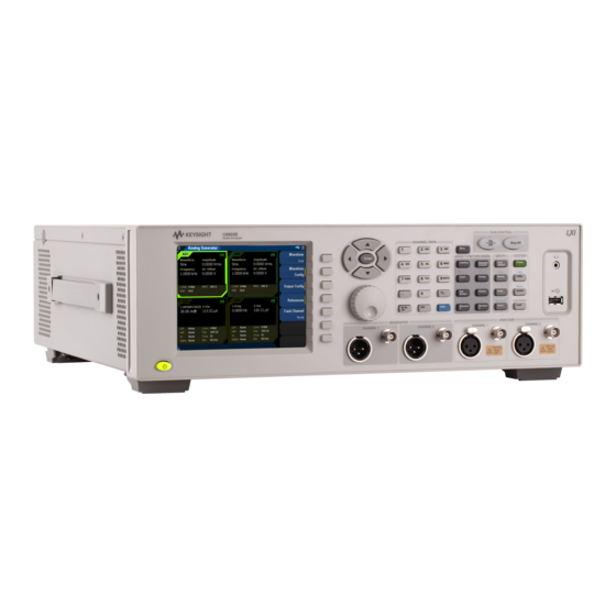
Keysight U8903B User Manual (605 pages)
Performance Audio
Brand:
Keysight
| Category:
Measuring Instruments
| Size: 39.59 MB
Table of Contents
Table of Contents
9
Declaration of Conformity
2
Safety Information
2
Safety Symbols
3
Safety Considerations
4
Environmental Conditions
5
Regulatory Information
6
Safety Compliance
6
EMC Compliance
6
Regulatory Markings
7
Sales and Technical Support
8
Waste Electrical and Electronic Equipment (WEEE) Directive 2002/96/EC
8
Product Category
8
Table of Contents
9
List of Figures
17
List of Tables
25
1 Getting Started
34
Introduction
34
LXI Standard 1.4 Compliant Audio Analyzer
34
Installation and Configuration
35
Initial Inspection
35
Rack Mounting
35
Ventilation
35
Standard Shipped Items
36
Optional Accessories
36
Table 1-1 U8903B Optional Accessories
36
U8903B Options
37
Table 1-2 U8903B Options
37
Product at a Glance
38
Front Panel
38
Table 1-3 U8903B Front Panel Description
38
Rear Panel
40
Table 1-4 U8903B Rear Panel Description
40
Figure 1-4 U8903B LCD Display
42
LCD Display
42
Table 1-5 U8903B LCD Display Description
43
Getting Started
44
Power on the U8903B
44
Preset the U8903B
44
Access the Help Mode
45
Figure 1-5 Help Mode
45
Figure 1-6 System > Update Menu Page
46
Table 1-6 System > Update Menu Page
46
Update the U8903B
46
Figure 1-7 Recall Menu Page
47
Figure 1-8 System > Service > Self-Test Menu Page
48
Perform Self-Test
48
Table 1-7 System > Service > Self-Test Menu Page
48
Add or Remove U8903B Options
49
Figure 1-9 System > Service > Options Menu Page
49
Table 1-8 System > Service > Options Menu Page
49
Figure 1-10 Recall Menu Page
50
2 Operation and Features
51
Figure 2-35 RUN CONTROL Panel
51
Test Capabilities
52
Analog Audio Interface
53
U8903B Block Diagram
53
Digital Audio Interface
55
Figure 2-3 U8903B Digital Generator and Analyzer Block Diagram
55
Bluetooth Audio Interface
56
Figure 2-4 U8903B Bluetooth Generator and Analyzer Block Diagram
56
Bluetooth Audio Connection Examples
57
Figure 2-7 Navigation and CHANNEL/DATA Panels
58
Navigation and CHANNEL/DATA Panels
58
Table 2-1 Navigation and CHANNEL/DATA Panels Description
58
Figure 2-8 U8903B Mode Selection
60
Menu Key
60
Table 2-2 U8903B Modes Description
60
Standard View
61
Hp8903B
62
Test Sequence Application (Test Seq App)
62
FUNCTION Panel
63
Table 2-3 FUNCTION Panel Description
63
Figure 2-9 Full Screen Graph Display
64
Full Screen
64
Display Mode
65
Figure 2-10 4-Panel View
65
Figure 2-11 10-Panel View
65
Figure 2-12 Graph Analysis Mode 2-Panel View
66
GRAPH Panel
67
Table 2-4 GRAPH Panel Description
67
Figure 2-13 Peak Search Menu Page
68
Peak Search
68
Table 2-5 Peak Search Menu Description
68
Figure 2-14 Peak Search > Threshold Menu Page
69
Table 2-6 Peak Search > Threshold Menu Description
69
Figure 2-15 Marker Menu
70
Marker
70
Table 2-7 Marker Menu Description
70
Figure 2-16 Marker > Marker - Menu Page
72
Table 2-8 Marker > Marker - Menu Description
72
Figure 2-17 Marker > Harmonics Menu Page
73
Table 2-9 Marker > Harmonics Menu Description
73
Figure 2-18 Scale Menu Page
74
Scale
74
Table 2-10 Scale Menu Description
74
Figure 2-19 Magnified Graph Display
75
Zoom
75
Edit Zoom
76
SYSTEM Panel
77
Table 2-11 SYSTEM Panel Description
77
Figure 2-21 Preset Menu Page
78
Preset
78
Table 2-12 Preset Menu Description
78
Figure 2-22 Utility Menu Page (Generator and Analyzer Mode)
79
Table 2-13 Utility Menu Description (Generator and Analyzer Mode)
79
Utility
79
Figure 2-23 Utility Menu Page (Graph Analysis Mode)
80
Table 2-14 Utility Menu Description (Graph Analysis Mode)
80
Figure 2-24 File Explorer Menu Page
81
Table 2-15 File Explorer Menu Description
81
Figure 2-25 System Menu
82
System
82
Figure 2-26 System > Error Info Menu Page (Error)
83
Table 2-16 Error Info Menu Description
83
Figure 2-27 System > I/O Menu Page
84
Table 2-17 I/O Menu Description
84
Table 2-18 System > I/O > Lan Settings Menu Description
85
Figure 2-29 System > Service Menu Page
86
Table 2-19 System > Service Menu Description
86
Table 2-20 System > Settings Menu Description
87
Figure 2-31 System > HP8903B Config Menu Page
89
Table 2-21 System > HP8903B Config Menu Description
89
Figure 2-32 System > Fan & Temperature Menu Page
90
Figure 2-33 System > aux Output Menu Page
91
Table 2-22 System > aux Output Menu Description
91
Figure 2-34 System > Board Info Menu Page
92
RUN CONTROL Panel
93
Table 2-23 Navigation and CHANNEL/DATA Panels Description
93
Figure 2-36 Save Menu Page
94
Save
94
Save and Recall
94
Table 2-24 Save Menu Description
94
Figure 2-37 Recall Menu Page
95
Recall
95
Table 2-25 Recall Menu Description
95
3 Audio Generator Functions
99
Audio Generator
99
Figure 3-1 Analog Generator Menu Page
99
Table 3-1 Analog Generator Menu Description
99
Figure 3-2 Digital Generator Menu Page
100
Table 3-2 Digital Generator Menu Description
100
Figure 3-3 Bluetooth Generator Menu Page
101
Table 3-3 Bluetooth Generator Menu Description
101
Waveform Configuration
102
Figure 3-4 Analog Generator > Waveform Config Menu Page (Sine Waveform)
102
Figure 3-5 Digital Generator > Waveform Config Menu Page (Sine Waveform)
102
Sine Waveform
102
Figure 3-6 Bluetooth Generator > Waveform Config Menu Page (Sine Waveform)
103
Table 3-4 Analog/Digital/Bluetooth Generator > Waveform Config Menu Description (Sine Waveform)
103
Figure 3-7 Analog Generator > Waveform Config Menu Page (Variable Phase Waveform)
104
Figure 3-8 Digital Generator > Waveform Config Menu Page (Variable Phase Waveform)
104
Variable Phase Waveform
104
Figure 3-9 Bluetooth Generator > Waveform Config Menu Page (Variable Phase Waveform)
105
Table 3-5 Analog/Digital/Bluetooth Generator > Waveform Config Menu Description (Variable Phase Waveform)
105
Dual Waveform
106
Figure 3-10 Analog Generator > Waveform Config Menu Page (Dual Waveform)
106
Figure 3-11 Digital Generator > Waveform Config Menu Page (Dual Waveform)
106
Figure 3-12 Bluetooth Generator > Waveform Config Menu Page (Dual Waveform)
107
Table 3-6 Analog/Digital/Bluetooth Generator > Waveform Config Menu Description (Dual Waveform)
107
Figure 3-13 Analog Generator > Waveform Config Menu Page (SMPTE 1:1 Waveform)
108
Figure 3-14 Digital Generator > Waveform Config Menu Page (SMPTE 1:1 Waveform)
108
SMPTE IMD Waveforms (1:1/4:1/10:1)
108
Figure 3-15 Bluetooth Generator > Waveform Config Menu Page (SMPTE 1:1 Waveform)
109
Table 3-7 Analog/Digital/Bluetooth Generator > Waveform Config Menu Description (SMPTE IMD Waveforms)
109
DFD IEC Waveforms (IEC 60118/IEC 60268)
110
Figure 3-16 Analog Generator > Waveform Config Menu Page (IEC 60118 Waveform)
110
Figure 3-17 Digital Generator > Waveform Config Menu Page (IEC 60118 Waveform)
110
Figure 3-18 Bluetooth Generator > Waveform Config Menu Page (IEC 60118 Waveform)
111
Table 3-8 Analog/Digital/Bluetooth Generator > Waveform Config Menu Description (IEC 60118 Waveform)
111
Figure 3-19 Analog Generator > Waveform Config Menu Page (IEC 60268 Waveform)
112
Figure 3-20 Digital Generator > Waveform Config Menu Page (IEC 60268 Waveform)
112
Figure 3-21 Bluetooth Generator > Waveform Config Menu Page (IEC 60268 Waveform)
113
Table 3-9 Analog/Digital/Bluetooth Generator > Waveform Config Menu Description (IEC 60268 Waveform)
113
Figure 3-22 Analog Generator > Waveform Config Menu Page (Gaussian Noise)
114
Figure 3-23 Digital Generator > Waveform Config Menu Page (Gaussian Noise)
114
Gaussian Noise
114
Figure 3-24 Bluetooth Generator > Waveform Config Menu Page (Gaussian Noise)
115
Table 3-10 Analog/Digital/Bluetooth Generator > Waveform Config Menu Description (Gaussian Noise)
115
Figure 3-25 Analog Generator > Waveform Config Menu Page (Rectangular Noise)
116
Figure 3-26 Digital Generator > Waveform Config Menu Page (Rectangular Noise)
116
Rectangular Noise
116
Figure 3-27 Bluetooth Generator > Waveform Config Menu Page (Rectangular Noise)
117
Table 3-11 Analog/Digital/Bluetooth Generator > Waveform Config Menu Description (Rectangular Noise)
117
Figure 3-28 Digital Generator > Waveform Config Menu Page (Triangular Noise)
118
Table 3-12 Digital Generator > Waveform Config Menu Description (Triangular Noise)
118
Triangular Noise
118
Figure 3-29 Analog Generator > Waveform Config Menu Page (Pink Noise)
119
Figure 3-30 Digital Generator > Waveform Config Menu Page (Pink Noise)
119
Pink Noise
119
Figure 3-31 Bluetooth Generator > Waveform Config Menu Page (Pink Noise)
120
Table 3-13 Analog/Digital/Bluetooth Generator > Waveform Config Menu Description (Pink Noise)
120
Figure 3-32 Analog Generator > Waveform Config Menu Page (Square Waveform)
121
Figure 3-33 Digital Generator > Waveform Config Menu Page (Square Waveform)
121
Square Waveform
121
Figure 3-34 Bluetooth Generator > Waveform Config Menu Page (Square Waveform)
122
Table 3-14 Analog/Digital/Bluetooth Generator > Waveform Config Menu Description (Square Waveform)
122
DC Signal
123
Figure 3-35 Analog Generator > Waveform Config Menu Page (DC Signal)
123
Table 3-15 Analog Generator > Waveform Config Menu Description (DC Signal)
123
Figure 3-36 Analog Generator > Waveform Config Menu Page (Sine Burst)
124
Figure 3-37 Digital Generator > Waveform Config Menu Page (Sine Burst)
124
Sine Burst Waveform
124
Figure 3-38 Bluetooth Generator > Waveform Config Menu Page (Sine Burst)
125
Table 3-16 Analog/Digital/Bluetooth Generator > Waveform Config Menu Description (Sine Burst)
125
Figure 3-39 Digital Generator > Waveform Config Menu Page (Stereo)
126
Stereo Waveform
126
Table 3-17 Digital Generator > Waveform Config Menu Description (Stereo)
126
Figure 3-40 Digital Generator > Waveform Config Menu Page (Monotonicity)
127
Monotonicity
127
Table 3-18 Digital Generator > Waveform Config Menu Description (Monotonicity)
127
Constant Value Waveform
128
Figure 3-41 Digital Generator > Waveform Config Menu Page (Constant)
128
Figure 3-42 Bluetooth Generator > Waveform Config Menu Page (Constant)
128
Table 3-19 Digital/Bluetooth Generator > Waveform Config Menu Description
129
Figure 3-43 Digital Generator > Waveform Config Menu Page (Walking Zero)
130
Table 3-20 Digital Generator > Waveform Config Menu Description (Walking Zero)
130
Walking Zero
130
Figure 3-44 Digital Generator > Waveform Config Menu Page (Walking One)
131
Table 3-21 Digital Generator > Waveform Config Menu Description (Walking One)
131
Walking One
131
Arbitrary Waveform
132
Figure 3-45 Analog Generator > Waveform Config Menu Page (Arbitrary Waveform)
132
Figure 3-46 Digital Generator > Waveform Config Menu Page (Arbitrary Waveform)
132
Figure 3-47 Bluetooth Generator > Waveform Config Menu Page (Arbitrary Waveform)
133
Table 3-22 Analog/Digital/Bluetooth Generator > Waveform Config Menu Description (Arbitrary Waveform)
133
Figure 3-48 Analog Generator > Waveform Config Menu Page 1 (Multitone Waveform)
134
Figure 3-49 Digital Generator > Waveform Config Menu Page 1 (Multitone Waveform)
134
Multitone Waveform
134
Figure 3-50 Bluetooth Generator > Waveform Config Menu Page 1 (Multitone Waveform)
135
Table 3-23 Analog/Digital/Bluetooth Generator > Waveform Config Menu Description (Multitone Waveform)
135
Figure 3-51 Analog Generator > Waveform Config > Custom Menu Page 1 (Multitone Waveform)
136
Figure 3-52 Digital Generator > Waveform Config > Custom Menu Page 1 (Multitone Waveform)
136
Figure 3-53 Bluetooth Generator > Waveform Config > Custom Menu Page 1 (Multitone Waveform)
137
Table 3-24 Analog/Digital/Bluetooth Generator > Waveform Config > Custom Menu Description (Multitone Waveform)
137
Dual-Tone Multi-Frequency (DTMF)
138
Figure 3-54 Analog Generator > Waveform Config Menu Page 1 (DTMF)
138
Figure 3-55 Dial Menu Page
139
Table 3-25 Analog Generator > Waveform Config Menu Description (DTMF)
139
Table 3-26 Dial Menu
140
Table 3-27 DTMF Tone Mapping
140
Output Configuration (Analog Generator)
141
Figure 3-56 Analog Generator > Output Config Menu Page
141
Table 3-28 Analog Generator > Output Config Menu Description
141
Output Configuration (Digital Generator)
143
Table 3-29 Digital Generator > Output Config Menu Description
143
Figure 3-58 Digital Generator > Output Config > Ref Clock Menu Page
144
Reference Clock
144
Table 3-30 Digital Generator > Output Config > Ref Clock Menu Description
144
Figure 3-59 Digital Generator > Output Config > Sync Clock Menu Page
145
Sync Clock
145
Table 3-31 Digital Generator > Output Config > Sync Clock Menu Description
145
Link Configuration (Bluetooth Generator)
146
Figure 3-60 Bluetooth Generator > Link Config Menu Page
146
Table 3-32 Bluetooth Generator > Link Config Menu Description
146
Device Scan
147
Figure 3-61 Bluetooth Analyzer > Link Config > Device Scan Menu Page
147
Table 3-33 Bluetooth Analyzer > Link Config > Device Scan Menu Description
147
Device Action
148
Figure 3-62 Bluetooth Analyzer > Link Config > Device Action Menu Page
148
Table 3-34 Bluetooth Analyzer > Link Config > Device Action Menu Description
148
Common Settings
150
Table 3-35 Bluetooth Analyzer > Link Config > Common Settings Menu Description
151
A2DP Settings
153
Figure 3-66 Bluetooth Analyzer > Link Config > A2DP Settings Menu Page
153
Table 3-36 Bluetooth Analyzer > Link Config > A2DP Settings Menu Description
153
Figure 3-67 Bluetooth Analyzer > Link Config > HFP Settings Menu Page
154
HFP Settings
154
Table 3-37 Bluetooth Analyzer > Link Config > HFP Settings Menu Description
154
AVRCP Log View
156
Figure 3-68 Bluetooth Analyzer > Link Config > AVRCP Log View Menu Page
156
Table 3-38 Bluetooth Analyzer > Link Config > AVRCP Log View Menu Description
156
DSI Output Configuration (Digital Generator)
157
Figure 3-69 Digital Generator > DSI Config Menu
157
Table 3-39 Digital Generator > DSI Output Config Menu Description
157
AES3/SPDIF Output Configuration (Digital Generator)
159
Figure 3-70 Digital Generator > AES Config Menu
159
Table 3-40 Digital Generator > AES Config Menu Description
159
Edit Bits (Consumer Format)
160
Table 3-41 Digital Generator > AES Config > Edit Bits (Consumer Format) Menu
160
Figure 3-71 Digital Generator > AES Config > Edit Bits (Consumer Format) Menu
161
Table 3-42 AES3/SPDIF Consumer Mode Bit Description
163
Edit Bits (Professional Format)
165
Figure 3-72 Digital Generator > AES Config > Edit Bits (Consumer Format) Menu
165
Table 3-43 Digital Generator > AES Config > Edit Bits (Professional Format) Menu
165
Table 3-44 AES3/SPDIF Professional Mode Bit Description
168
References (Analog Generator)
171
Figure 3-73 Analog Generator > References Menu Page
171
Table 3-45 Analog Generator > References Menu Description
171
References (Digital and Bluetooth Generator)
172
Figure 3-74 Digital Generator > References Menu Page
172
Figure 3-75 Bluetooth Generator > References Menu Page
172
Table 3-46 Digital/Bluetooth Generator > References Menu Description
172
4 Audio Analyzer Measurement Functions
175
Audio Analyzer
175
Figure 4-1 Analog Analyzer Menu Page
175
Figure 4-2 Digital Analyzer Menu Page (Standard Measurement Mode)
176
Table 4-1 Analog Analyzer Menu Description
176
Table 4-2 Digital Analyzer Menu Description
177
Figure 4-3 Bluetooth Analyzer Menu Page
178
Table 4-3 Bluetooth Analyzer Menu Description
178
Figure 4-4 Digital Analyzer Menu Page (Process Delay Measurement Mode)
179
Measurement Mode (Digital Analyzer)
179
Figure 4-5 Digital Analyzer Menu Page (BERT Measurement Mode)
180
Table 4-4 Digital Analyzer > Meas Mode > BERT Menu Description
181
Functions
182
Figure 4-6 Analog Analyzer > Functions Menu
182
Figure 4-7 Digital Analyzer > Functions Menu
182
Figure 4-8 Bluetooth Analyzer > Functions Menu
183
Table 4-5 Analog/Digital/Bluetooth Analyzer > Functions Menu Description
183
Measurement Functions
184
Figure 4-9 Analog Analyzer > Functions > Frequency Menu
184
Frequency Measurement
184
Figure 4-10 Digital Analyzer > Functions > Frequency Menu
185
Figure 4-11 Bluetooth Analyzer > Functions > Frequency Menu
185
Table 4-6 Analog/Digital/Bluetooth Analyzer > Functions > Frequency Menu Description
185
AC Voltage Level Measurement
187
Figure 4-12 Analog Analyzer > Functions > AC Voltage Menu
187
Figure 4-13 Digital Analyzer > Functions > AC Voltage Menu
188
Figure 4-14 Bluetooth Analyzer > Functions > AC Voltage Menu
188
Table 4-7 Analog/Digital/Bluetooth Analyzer > Functions > AC Voltage Menu
189
DC Voltage Level Measurement
191
Figure 4-15 Analog Analyzer > Functions > DC Voltage Menu
191
Figure 4-16 Digital Analyzer > Functions > DC Voltage Menu
192
Figure 4-17 Bluetooth Analyzer > Functions > DC Voltage Menu
192
Table 4-8 Analog/Digital/Bluetooth Analyzer > Functions > DC Voltage Menu Description
193
THD+N Ratio and THD+N Level Measurements
194
Figure 4-19 Digital Analyzer > Functions > THD+N Ratio Menu
195
Figure 4-20 Bluetooth Analyzer > Functions > THD+N Ratio Menu
195
Table 4-9 Analog/Digital/Bluetooth Analyzer > Functions > THD+N Ratio Menu
196
Figure 4-21 Analog Analyzer > Functions > THD+N Level Menu
197
Figure 4-22 Digital Analyzer > Functions > THD+N Level Menu
197
Figure 4-23 Bluetooth Analyzer > Functions > THD+N Level Menu
198
Table 4-10 Analog/Digital/Bluetooth Analyzer > Functions > THD+N Level Menu
198
Figure 4-24 Analog Analyzer > Functions > SINAD Menu
200
Figure 4-25 Digital Analyzer > Functions > SINAD Menu
200
SINAD Measurement
200
Figure 4-26 Bluetooth Analyzer > Functions > SINAD Menu
201
Table 4-11 Analog/Digital/Bluetooth Analyzer > Functions > SINAD Menu Description
201
THD Ratio and THD Level Measurements
203
Figure 4-28 Digital Analyzer > Functions > THD Ratio Menu
204
Figure 4-29 Bluetooth Analyzer > Functions > THD Ratio Menu
204
Table 4-12 Analog/Digital/Bluetooth Analyzer > Functions > THD Ratio Menu
204
Figure 4-30 Analog Analyzer > Functions > THD Level Menu
206
Figure 4-31 Digital Analyzer > Functions > THD Level Menu
206
Figure 4-32 Bluetooth Analyzer > Functions > THD Level Menu
207
Table 4-13 Analog/Digital/Bluetooth Analyzer > Functions > THD Level Menu Description
207
Figure 4-33 Analog Analyzer > Functions > SMPTE IMD Menu
210
SMPTE IMD Measurements
210
Figure 4-34 Digital Analyzer > Functions > SMPTE IMD Menu
211
Table 4-14 Analog/Digital/Bluetooth Analyzer > Functions > SMPTE IMD Menu
212
DFD Measurements
213
Table 4-15 Analog/Digital/Bluetooth Analyzer > Functions > DFD Measurements Menu
214
SNR Measurement
215
Table 4-16 Analog Analyzer > Functions > SNR Menu Description
216
SNR (Fast Mode) Measurement
217
Table 4-17 Analog/Bluetooth Analyzer > Functions > SNR (Fast) Menu Description
218
J-Test Measurement
220
Positive Peak Measurement
221
Table 4-18 Digital Analyzer > Functions > Positive Peak Menu Description
221
Negative Peak Measurement
223
Table 4-19 Digital Analyzer > Functions > Negative Peak Menu Description
223
Phase Measurement
225
Table 4-20 Analog/Digital/Bluetooth Analyzer > Functions > Phase Menu Description
227
Crosstalk Measurement
228
Table 4-21 Analog/Digital/Bluetooth Analyzer > Functions > X-Talk Menu Description
229
Filters Configuration (Analog Analyzer)
231
Table 4-22 Analog Analyzer > Filter Config Menu Description
231
Notch Filter
233
Table 4-23 Analog Analyzer > Filter Config > Notch Filter Menu Description
233
Filters Configuration (Digital Analyzer)
234
Table 4-24 Digital Analyzer > Filter Config Menu Description
234
Filters Configuration (Bluetooth Analyzer)
236
Table 4-25 Bluetooth Analyzer > Filter Config Menu Description
236
Notch Filter
237
Table 4-26 Bluetooth Analyzer > Filter Config > Notch Filter Menu Description
237
Measurement Configuration (Analog Analyzer)
238
Table 4-27 Analog Analyzer > Meas Config Menu Description
238
Measurement Configuration (Digital Analyzer)
240
Table 4-28 Digital Analyzer > Meas Config Menu Description
240
Measurement Configuration (Bluetooth Analyzer)
242
Table 4-29 Bluetooth Analyzer > Meas Config Menu Description
242
Trigger (Analog, Digital, and Bluetooth Analyzer)
244
Table 4-30 Digital Analyzer > Meas Config > Trigger Menu Description
245
Input Configuration (Analog Analyzer)
246
Table 4-31 Analog Analyzer > Input Config Menu Description
246
Input Configuration (Digital Analyzer)
248
Table 4-32 Digital Analyzer > Input Config Menu Description
248
Link Configuration (Bluetooth Analyzer)
250
DSI Input Configuration (Digital Analyzer)
251
Table 4-33 Digital Analyzer > DSI Config Menu Description
251
AES/SPDIF Input Configuration (Digital Analyzer)
253
Table 4-34 Digital Analyzer > AES Config Menu Description
253
Bits Analysis (Digital Analyzer)
254
Table 4-35 Digital Analyzer > Bits Analysis Menu Description
254
Wave File (Analog, Digital, and Bluetooth Analyzer)
255
Table 4-36 Analog/Digital/Bluetooth Analyzer > Wave File Menu Description
256
Statistics
257
Table 4-37 Analog/Digital/Bluetooth Analyzer > Statistics Menu Description
258
5 Graph Analysis
259
5 Graph Analysis
260
Table 5-1 Graph Analysis Menu Description
261
Graph Settings
262
Table 5-2 Graph Analysis > Graph Settings Menu Description
262
Axis Settings
264
Table 5-3 Graph Analysis > Axis Settings Menu Description
264
Table 5-4 Graph Analysis > Trace Settings Menu Description
266
Trace Settings
266
Memory
268
Table 5-5 Graph Analysis > Trace Settings > Memory Menu Description
268
Math
269
Table 5-6 Graph Analysis > Trace Settings > Math Menu Description
269
Persistence
270
Table 5-7 Graph Analysis > Trace Settings > Persistence Menu Description
270
Display Options
271
Graph
271
Data Table
272
Marker Table
272
Harmonics
273
Statistics
273
Table 5-8 Graph Analysis > Harm Settings Menu Description (Harmonics Display)
274
Signal Analysis
275
Measurement Settings
276
Table 5-9 Graph Analysis > Measurement Menu Description
276
Measurement 1/Measurement 2
277
Table 5-10 Graph Analysis > Measurement > Measurement 1/Measurement 2 Menu
277
Sweep Parameter
280
Table 6-1 Sweep Parameter Menu Description
281
Group Delay
282
Points Settings
283
Table 6-2 Sweep Parameter > Points Settings Menu Description
283
Sweep Channels
284
Table 6-3 Sweep Parameter > Channels Menu Description
284
Plot View
285
Table 6-4 Sweep > Plot View Menu Description
285
Axis Settings
286
Table 6-5 Sweep > Plot View > Axis Settings Menu Description
286
Plot Settings
287
Table 6-6 Sweep > Plot View > Plot Settings Menu Description
287
Edit Points
289
Table 6-7 Sweep > Edit Points Menu Description
289
7 Test Sequence Application
291
7 Test Sequence Application
292
7 Test Sequence Application
293
Table 7-1 Test Application Menu Description
294
Project
295
Table 7-2 TSA > Project Menu Description
295
Properties
296
Table 7-3 TSA > Project > Properties Menu Description
296
Table 7-4 TSA > Project > Test Menu Description
297
Test Sequence
297
IO Configuration
298
Table 7-5 TSA > Project > Test > IO Configuration Menu Description
298
Settings
299
Table 7-6 TSA > Project > Test > IO Configuration > Output Configuration Menu
300
Table 7-7 TSA > Project > Test > IO Configuration > Output Configuration Menu Description (Bluetooth)
301
Table 7-8 TSA > Project > Test > IO Configuration > Input Configuration Menu Description (Analog)
302
Properties
306
Table 7-10 TSA > Project > Test > IO Configuration > Properties Menu Description
306
Sub-Steps
307
Table 7-11 Sub-Step Menu Description
307
Prompt Sub-Step Settings
308
Table 7-12 Prompt Sub-Step Settings Menu Description
308
Send SCPI Sub-Step Settings
309
Table 7-13 Send SCPI Sub-Step Settings Menu Description
309
Measurements
310
Table 7-14 TSA > Project > Test > Measurement Menu Description
310
Properties
312
Table 7-15 TSA > Project > Test > Measurement > Properties Menu Description
312
AC Level
313
Table 7-16 TSA > Project > Test > AC Level > Settings > Signal Generation Menu
314
Table 7-17 TSA > Project > Test > AC Level > Settings > Signal Analysis Menu
315
Frequency
316
Table 7-18 Frequency > Signal Generation Settings Menu Description
317
Table 7-19 Frequency > Signal Analysis Settings Menu Description
318
Phase
319
Table 7-20 Phase > Signal Generation Settings Menu Description
320
Table 7-21 Phase > Signal Analysis Settings Menu Description
321
Snr
322
Table 7-22 SNR > Signal Generation Settings Menu Description
323
Table 7-23 SNR > Signal Analysis Settings Menu Description
324
Thd+N
327
Table 7-24 THD+N > Signal Generation Settings Menu Description
328
Table 7-25 THD+N > Signal Analysis Settings Menu Description
329
DC Level
331
Table 7-26 DC Level > Signal Generation Settings Menu Description
332
Table 7-27 DC Level > Signal Analysis Settings Menu Description
333
Crosstalk
334
Table 7-28 Crosstalk > Signal Generation Settings Menu Description
335
Table 7-29 Crosstalk > Signal Analysis Settings Menu Description
336
Smpte IMD
337
Table 7-30 SMPTE IMD > Signal Generation Settings Menu Description
338
Table 7-31 SMPTE IMD > Signal Analysis Settings Menu Description
339
Dfd IMD
340
Table 7-32 DFD IMD > Signal Generation Settings Menu Description
341
Table 7-33 DFD IMD > Signal Analysis Settings Menu Description
342
Multitone Analyzer
343
Table 7-34 Multitone Analyzer > Signal Generation Settings Menu Description
344
Table 7-35 Multitone Analyzer > Signal Analysis Settings Menu Description
345
Stepped Frequency Sweep
346
Table 7-36 Stepped Frequency Sweep > Signal Generation Settings Menu Description
347
Table 7-37 Stepped Frequency Sweep > Signal Analysis Settings Menu Description
348
SMPTE Frequency Sweep
351
Table 7-38 SMPTE Frequency Sweep > Signal Generation Settings Menu Description
352
Table 7-39 SMPTE Frequency Sweep > Signal Analysis Settings Menu Description
353
DFD Frequency Sweep
354
Table 7-40 DFD Frequency Sweep > Signal Generation Settings Menu Description
355
Table 7-41 DFD Frequency Sweep > Signal Analysis Settings Menu Description
356
External Frequency Sweep
358
Table 7-42 External Frequency Sweep > Signal Generation Settings Menu Description
358
Table 7-43 External Frequency Sweep > Signal Analysis Settings Menu Description
360
Stepped Level Sweep
363
Table 7-44 Stepped Level Sweep > Signal Generation Settings Menu Description
364
Table 7-45 Stepped Level Sweep > Signal Analysis Settings Menu Description
365
SMPTE Level Sweep
368
Table 7-46 SMPTE Level Sweep > Signal Generation Settings Menu Description
369
Table 7-47 SMPTE Level Sweep > Signal Analysis Settings Menu Description
370
DFD Level Sweep
372
Table 7-48 DFD Level Sweep > Signal Generation Settings Menu Description
373
Table 7-49 DFD Level Sweep > Signal Analysis Settings Menu Description
374
DC Level Sweep
376
Table 7-50 DC Level Sweep > Signal Generation Settings Menu Description
377
Table 7-51 DC Level Sweep > Signal Analysis Settings Menu Description
378
Receiver Sensitivity
380
Table 7-52 Receiver Sensitivity > Signal Generation Settings Menu Description
381
Table 7-53 Receiver Sensitivity > Signal Analysis Settings Menu Description
382
External Level Sweep
385
Table 7-54 External Level Sweep > Signal Generation Settings Menu Description
385
Table 7-55 Stepped Level Sweep > Signal Analysis Settings Menu Description
387
Measurement Recorder
390
Table 7-56 Measurement Recorder > Signal Generation Settings Menu Description
391
Table 7-57 Measurement Recorder > Signal Analysis Settings Menu Description
392
Voice Quality
395
Table 7-58 Voice Quality > Signal Generation and Analysis Settings Menu Description
396
Measurement Results
399
Table 7-59 TSA > Project > Test > Measurement > Settings > Result (Bar Chart) Menu
399
Table 7-60 TSA > Project > Test > Measurement > Settings > Result (Graph) Menu
401
Report
403
Table 7-61 TSA > Report Menu Description
403
Properties
404
Table 7-62 TSA > Report > Properties Menu Description
404
8 Hp8903B
407
Hp8903B
408
Table 8-1 U8903B LCD Display Description
409
Measurement
410
Table 8-2 HP8903B > Measurement Menu Description
410
Table 8-3 HP8903B Unit Charts
411
Generator
412
Table 8-4 HP8903B > Generator Menu Description
412
Sweep
413
Table 8-5 HP8903B > Sweep Menu Description
413
Special Function Code List
414
Table 8-6 HP8903B Special Function Code List Description
414
Floating Input
416
Spcl
416
Table 8-7 Floating Input Settings
416
Table 8-8 Floating Output Settings
416
Table 8-9 Floating Output Settings and Special Functions to Change the Generator Impedance
416
9 Characteristics and Specifications
417
9 Characteristics and Specifications
418
Appendixes
419
A Appendixes
420
Appendix 1: FUNCTION Panel
421
Table A-1 FUNCTION Panel Description
421
Appendix 2: Graph Panel Menu Tree
422
Table A-2 GRAPH Panel Menu Tree Description
422
Appendix 3: System Panel Menu Tree
424
Table A-3 SYSTEM Panel Menu Tree Description
424
Appendix 4: Analog Generator Menu Tree
428
Table A-4 Analog Generator Menu Tree Description
428
Appendix 5: Digital Generator Menu Tree
432
Table A-5 Digital Generator Menu Tree Description
432
Appendix 6: Bluetooth Generator Menu Tree
443
Table A-6 Bluetooth Generator Menu Tree Description
443
Appendix 7: Analog Analyzer Menu Tree
450
Table A-7 Analog Analyzer Menu Tree Description
450
Appendix 8: Digital Analyzer Menu Tree
462
Table A-8 Digital Analyzer Menu Tree Description
462
Appendix 9: Bluetooth Analyzer Menu Tree
474
Table A-9 Bluetooth Analyzer Menu Tree Description
474
Appendix 10: Graph Analysis Menu Tree
486
Table A-10 Graph Analysis Menu Tree Description
486
Appendix 11: Sweep Function Menu Tree
490
Table A-11 Sweep Function Menu Tree Description
490
Appendix 12: Save Menu Tree
493
Table A-12 Save Menu Tree Description
493
Appendix 13: Recall Menu Tree
494
Table A-13 Recall Menu Tree Description
494
Appendix 14: Test Sequence Menu Tree
495
Table A-14 Test Sequence Menu Tree Description
495
Measurement Settings
503
Table A-15 Measurement Settings > AC Level Menu Tree Description
503
Table A-16 Measurement Settings > Frequency Menu Tree Description
505
Table A-17 Measurement Settings > Phase Menu Tree Description
506
Table A-18 Measurement Settings > SNR Menu Tree Description
507
Table A-19 Measurement Settings > THD+N Menu Tree Description
510
Table A-20 Measurement Settings > DC Level Menu Tree Description
512
Table A-21 Measurement Settings > Crosstalk Menu Tree Description
513
Table A-22 Measurement Settings > SMPTE IMD Menu Tree Description
514
Table A-23 Measurement Settings > DFD IMD Menu Tree Description
515
Table A-24 Measurement Settings > Multitone Analyzer Menu Tree Description
516
Table A-25 Measurement Settings > Stepped Frequency Sweep Menu Tree Description
518
Table A-26 Measurement Settings > SMPTE Frequency Sweep Menu Tree Description
521
Table A-27 Measurement Settings > DFD Frequency Sweep Menu Tree Description
523
Table A-28 Measurement Settings > External Frequency Sweep Menu Tree Description
525
Table A-29 Measurement Settings > Stepped Level Sweep Menu Tree Description
528
Table A-30 Measurement Settings > SMPTE Level Sweep Menu Tree Description
531
Table A-31 Measurement Settings > DFD Level Sweep Menu Tree Description
533
Table A-32 Measurement Settings > DC Level Sweep Menu Tree Description
535
Table A-33 Measurement Settings > Receiver Sensitivity Menu Tree Description
537
Table A-34 Measurement Settings > External Level Sweep Menu Tree Description
540
Table A-35 Measurement Settings > Measurement Recorder Menu Tree Description
543
Table A-36 Measurement Settings > Voice Quality Menu Tree Description
546
Measurement Results
548
Table A-37 Measurement Results > Bar Chart Menu Tree Description
548
Table A-38 Measurement Results > Graph Menu Tree Description
549
Appendix 15: HP8903B Menu Tree
552
Table A-39 HP8903B Menu Tree Description
552
Appendix 16: Units of the Measurement Function Returned Values
554
Analog Analyzer
554
Table A-40 Analog Analyzer Units of the Meaurement Function Returned Values
554
Digital Analyzer
555
Table A-41 Digital Analyzer Units of the Meaurement Function Returned Values
555
Bluetooth Analyzer
556
Table A-42 Bluetooth Analyzer Units of the Meaurement Function Returned Values
556
Table A-43 Unit Conversion Formula
557
Table A-44 Units for Digital Audio Measurements
558
Units for Digital Audio Measurements
558
Appendix 17: Arbitrary File Format
559
Table A-45 Allowable Range for Arbitrary File Parameters
559
Appendix 18: User-Defined Filter File Format
561
Appendix 19: DSI Input and Output Interface
564
Table A-46 25-Pin Female D-SUB Connector Pins Assignment
564
Appendix 20: Digital System Clock Distribution Block Diagram
565
Appendix 21: Typical DSI Test Configurations
566
Configuration 1
566
Configuration 2
567
Configuration 3
568
Configuration 4
569
Configuration 5
570
Appendix 22: U8903B Configuration Examples
571
Example 1: Generating a Sine Waveform with the Digital Generator and Measuring Its Voltage with the Digital Analyzer
571
Example 2: Establishing a Connection to a Bluetooth Device and Generating a Sine Waveform with the Bluetooth Generator
573
Example 3: Generating a Multitone Waveform with the Analog Generator and Viewing the Multitone Spectrum in the Graph
575
Example 4: Running the Test Sequence App for the Multitone Analyzer Measurement
577
Example 5: Configuring the System Clock Reference Settings
579
Example 6: Configuring the Digital Generator DSI Output Settings
580
Appendix 23: Relationship between Digital Waveform Parameters and Channels
581
Table A-47 Relationship between Digital Waveform Parameters and Channels
581
Appendix 24: Word Length, Sampling Rate, and Multiplier for DSI
583
Table A-48 Word Length, Sampling Rate, and Multiplier for DSI
583
Appendix 25: Word Length, Sampling Rate, and Multiplier for Master Clock in
589
Table A-49 Word Length, Sampling Rate, and Multiplier for Master Clock in
589
Appendix 26: U8903B Default Settings
595
Analog Generator
595
Table A-50 Analog Generator Default Settings
595
Analog Analyzer
596
Table A-51 Analog Analyzer Default Settings
598
Sweep
599
Table A-52 Sweep Default Settings
599
Hp8903B
600
System
600
Table A-53 HP8903B Default Settings
600
Table A-54 System Default Settings
600
Appendix 27: Procedure to Rename, Copy, Move, and Delete Files
601
Renaming a File
601
Copying a File
601
Moving a File
601
Deleting a File
601
Appendix 28: POLQA Recording Duration Analysis
602
Table A-55 U8903B Option Configuration
602
Table A-56 Maximum Wave File Recording Duration for the POLQA Narrowband and Super-Wideband Analysis
602
Appendix 29: Audio Measurement Ranging
603
Manual Ranging
603
Auto Ranging
603
Using Manual Ranging for Continuous Sweep and Frequency Response Measurements
604
Advertisement
Keysight U8903B Service Manual (165 pages)
Performance Audio Analyzer
Brand:
Keysight
| Category:
Measuring Instruments
| Size: 3.96 MB
Table of Contents
Declaration of Conformity
2
Safety Information
2
Safety Symbols
3
Safety Considerations
4
Environmental Conditions
5
Table of Contents
9
List of Figures
13
List of Tables
15
1 Performance Verification Overview Introduction
18
Figure 1-1 Process Flow for Self-Test, Performance Tests, and Repair
18
Calibration Interval
19
Keysight Calibration Services
19
Self-Test
19
Recommended Test Equipment
20
Table 1-1 Recommended Equipment for Performance Verification Tests
20
Test Consideration
21
2 Performance Verification for Analog Generator
23
Introduction
24
Performance Verification
25
DC Accuracy Verification
25
Figure 2-1 U8903B to Digital Multimeter Connections for DC Accuracy Verification
25
Table 2-1 DC Accuracy Specification
25
Performance Verification for Analog Generator
25
Sine Wave Amplitude Accuracy and Flatness Verification
26
Table 2-2 Sine Wave Amplitude Accuracy and Flatness Specifications
26
Figure 2-2 U8903B to Digital Multimeter Connections for Sine Wave Amplitude Accuracy and Flatness Verification
27
Sine Wave Frequency Accuracy Verification
29
Figure 2-3 U8903B to Frequency Counter Connections for Frequency Accuracy
29
Table 2-3 Frequency Accuracy Specifications
29
Crosstalk Verification
30
Table 2-4 Crosstalk Specification
30
Figure 2-4 U8903B Audio Analyzer Connections for Crosstalk Verification
31
Square Wave Rise Time Verification
32
Table 2-5 Square Wave Rise Time Specification
32
Square Wave Amplitude Accuracy Verification
34
Figure 2-6 U8903B to Digital Multimeter Connections for Square Wave Amplitude Accuracy Verification
34
Table 2-6 Square Wave Amplitude Accuracy Specification
34
3 Performance Verification for Analog Analyzer
37
3 Performance Verification for Analog Analyzer
38
Introduction
38
Performance Verification
39
DC Accuracy Verification
39
Figure 3-1 Calibrator to U8903B Connection for DC Accuracy Verification
39
Table 3-1 DC Accuracy Specification
39
AC Accuracy and Flatness Verification
40
Table 3-2 AC Accuracy and Flatness Specifications
40
Figure 3-2 Calibrator to U8903B Connection for AC Accuracy and Flatness Verification
41
Frequency Accuracy Verification
42
Table 3-3 Frequency Accuracy Specifications
42
Figure 3-3 Function Generator to Frequency Counter and U8903B Connection for Frequency Accuracy Verification
43
Phase Accuracy Verification
44
Table 3-4 Phase Accuracy Specification
44
Figure 3-4 Function Generator to U8903B Connection for Phase Accuracy Verification
45
Crosstalk Verification
46
Figure 3-5 Audio Generator to U8903B with Terminator Connection for Crosstalk Verification
46
Table 3-5 Crosstalk Specification
46
CMRR Verification
48
Figure 3-6 Audio Generator to U8903B Connection for CMRR Verification
48
Table 3-6 CMRR Specification
48
Distortion (THD+N) Verification
50
Table 3-7 Distortion Specification
50
SMTPE IMD Verification
51
Table 3-8 SMTPE IMD Specification
51
DFD Verification
53
Table 3-9 DFD Specification
53
Residual Noise Verification
54
Table 3-10 Residual Noise Specification
54
Wideband AC Flatness Verification
55
Table 3-11 Wideband Sine Wave Flatness Specifications
55
Figure 3-7 Function Generator to U8903B and Digital Multimeter for Wideband Sine Wave Flatness Verification
56
Wideband Frequency Accuracy Verification
57
Table 3-12 Wideband Frequency Accuracy Specifications
57
Figure 3-8 Function Generator to Frequency Counter and U8903B Connection for Wideband Frequency Accuracy Verification
58
4 Performance Verification for Digital Generator and Digital Analyzer
62
U8903B Options
62
Table 4-1 U8903B Digital Interface Options
62
Performance Verification
63
DSI Master Clock Output Frequency Accuracy Verification
63
Figure 4-1 Keysight 53132A/53220A to DSI MCLK Output for Balanced DSI Master Clock Output Frequency Accuracy Verification
63
Table 4-2 DSI Master Clock Output Frequency Accuracy Specification
63
Balanced Output Level Accuracy Verification
68
Figure 4-2 DSO8064A Oscilloscope to U8903B Balanced Digital Output for Balanced Out- Put Level Accuracy Verification
68
Table 4-3 Balanced Output Level Accuracy Specification
68
Table 4-4 Channel 1 and Channel 2 Vertical Scale and Vertical Scale Range
69
Balanced Input Sampling Rate Accuracy Verification
71
Figure 4-3 Keysight 53132A/53220A to U8903B Balanced Digital Output for Balanced Input Sampling Rate Accuracy Verification
71
Table 4-5 Balanced Input Sampling Rate Accuracy Specification
71
Figure 4-4 U8903B Balanced Digital Output to Its Own Balanced Digital Input for Bal- Anced Input Sampling Rate Accuracy Verification
72
Balanced Output Sampling Rate Accuracy Verification
74
Figure 4-5 Keysight 53132A/53220A to U8903B Balanced Digital Output for Balanced Output Sampling Rate Accuracy Verification
74
Table 4-6 Balanced Output Sampling Rate Accuracy Specification
74
Unbalanced Output Level Accuracy Verification
76
Figure 4-6 DSO8064A Oscilloscope to U8903B Unbalanced Digital Output for Unbalanced Output Level Accuracy Verification
76
Table 4-7 Unbalanced Output Level Accuracy Specification
76
Table 4-8 Channel 1 Vertical Scale Settings
77
Unbalanced Input Sampling Rate Accuracy Verification
78
Figure 4-7 Keysight 53132A/53220A to U8903B Unbalanced Digital Output for Unbalanced Input Sampling Rate Accuracy Verification
78
Table 4-9 Unbalanced Input Sampling Rate Accuracy Specification
78
Figure 4-8 U8903B Unbalanced Digital Output to Its Own Unbalanced Digital Input for Unbalanced Input Sampling Rate Accuracy Verification
79
Unbalanced Output Sampling Rate Accuracy Verification
81
Figure 4-9 Keysight 53132A/53220A to U8903B Unbalanced Digital Output for Unbal
81
Table 4-10 Unbalanced Output Sampling Rate Accuracy Specification
81
5 Performance Verification for Bluetooth Card
83
U8903B Bluetooth Options
84
Performance Verification for Bluetooth Card
84
Table 5-1 U8903B Bluetooth Interface Options
84
U8903B Bluetooth Card Verification
85
Equipment Used
85
Test Program
85
Test Procedure
85
Figure 5-1 Connecting the U8903B Tester RF1 Port to DUT RF1 Port for Keysight U8903B Bluetooth Card Functional Verification
85
Figure 5-2 Unit ID Text Box
86
Figure 5-3 U8903B-BT Tester Connection Status
86
Figure 5-4 U8903B-BT Tester Bluetooth Address
86
Figure 5-5 DUT Hardware and Software Information
87
Figure 5-6 DUT Bluetooth Address
87
Figure 5-7 U8903B Tester Unit to the DUT Connection Reminder Window
87
U8903B Bluetooth Test Description
88
Handsfree Profile (HFP) Test Description
88
Figure 5-8 U8903B Bluetooth Test for HFP Profile (BT Role: Initator, Audio Role: AG)
88
Figure 5-9 U8903B Bluetooth Test for HFP Profile (BT Role: Responder, Audio Role: HF)
89
Table 5-2 HFP Bluetooth Audio Test Points and Limits for Analyzer and Generator
90
Table 5-3 Wideband HFP Bluetooth Audio Test Points and Limits for Analyzer and Generator
90
Advanced Audio Distribution Profile (A2DP) Test Description
91
Figure 5-10 U8903B Bluetooth Test for A2DP Profile (BT Role: Initator, Audio Role: SRC)
91
Figure 5-11 U8903B Bluetooth Test for A2DP Profile (BT Role: Responder, Audio Role: SNK)
92
Table 5-4 A2DP Bluetooth Audio Test Points and Limits for Analyzer and Generator
93
Table 5-5 A2DP APTX Functional Test Points and Limits for Analyzer and Generator
93
U8903B Bluetooth Retest Procedure
94
Figure 5-12 U8903B Bluetooth Retest Procedure
94
Table 5-6 U8903B Bluetooth Test to be Repeated and Its Prerequisite
94
Table A-8 Test Record for DC Accuracy Verification
97
A Appendix A
98
Analog Generator Performance Verification
98
Test Record for DC Accuracy Verification
98
Table A-1 Test Record for DC Accuracy Verification
98
Test Record for Sine Wave Amplitude Accuracy Verification
100
Table A-2 Test Record for Sine Wave Amplitude Accuracy Verification
100
Test Record for Flatness Verification
101
Table A-3 Test Record for Flatness Verification
101
Test Record for Frequency Accuracy Verification
102
Test Record for Crosstalk Verification
102
Table A-4 Test Record for Frequency Accuracy Verification
102
Test Record for Square Wave Rise Time Verification
103
Table A-5 Test Record for Crosstalk Verification
103
Table A-6 Test Record for Square Wave Rise Time Verification
103
Test Record for Square Wave Amplitude Accuracy Verification
104
Table A-7 Test Record for Square Wave Amplitude Accuracy Verification
104
Analog Analyzer Performance Verification
105
Test Record for DC Accuracy Verification
105
Test Record for AC Accuracy and Flatness Verification
106
Table A-9 Test Record for AC Accuracy and Flatness Verification
106
Test Record for Frequency Accuracy Verification
111
Test Record for Phase Accuracy Verification
111
Table A-10 Test Record for Frequency Accuracy Verification
111
Table A-11 Test Record for Phase Accuracy Verification
111
Test Record for Crosstalk Verification
112
Table A-12 Test Record for Crosstalk Verification
112
Test Record for CMRR Verification
113
Table A-13 Test Record for CMRR Verification
113
Test Record for Distortion Verification
114
Table A-14 Test Record for Distortion Verification
114
Test Record for SMPTE IMD Verification
115
Table A-15 Test Record for SMPTE IMD Verification
115
Test Record for DFD Verification
116
Table A-16 Test Record for DFD Verification
116
Test Record for Residual Noise Verification
117
Test Record for Wideband Sine Wave Flatness Verification
117
Table A-17 Test Record for Residual Noise Verification
117
Table A-18 Test Record for Wideband Sine Wave Flatness Verification
117
Test Record for Wideband Frequency Accuracy Verification
125
Table A-19 Test Record for Wideband Frequency Accuracy Verification
125
Table B-1 Test Record for DSI Master Clock Output Frequency Accuracy Verification
127
Table B-4 Test Record for Balanced Output Sampling Rate Accuracy Verification
127
Digital Generator and Digital Analyzer Performance Verification
128
Test Record for DSI Master Clock Output Frequency Accuracy Verification
128
Test Record for Balanced Output Level Accuracy Verification
141
Table B-2 Test Record for Balanced Output Level Accuracy Verification
141
Test Record for Balanced Input Sampling Rate Accuracy Verification
147
Table B-3 Test Record for Balanced Input Sampling Rate Accuracy Verification
147
Test Record for Balanced Output Sampling Rate Accuracy Verification
150
Test Record for Unbalanced Output Level Accuracy Verification
152
Table B-5 Test Record for Unbalanced Output Level Accuracy Verification
152
Test Record for Unbalanced Input Sampling Rate Accuracy Verification
155
Table B-6 Test Record for Unbalanced Input Sampling Rate Accuracy Verification
155
Test Record for Unbalanced Output Sampling Rate Accuracy Verification
158
Table B-7 Test Record for Unbalanced Output Sampling Rate Accuracy Verification
158
C Appendix C
162
100 C Appendix C
162
Modify a Cable for the U8903B CMRR Test
162
Figure C-1 8120-1840 BNC Cable
162
Figure C-2 Male End of the XLR Cable
162
Figure C-3 Uncover the Soldering Wire
162
Table C-1 Parts to Order
162
Figure C-4 De-Solder the Wires
163
Figure C-5 Solder the BNC Cable to the Male End of the XLR Cable
163
Keysight U8903B Quick Start Manual (15 pages)
Performance Audio Analyzer
Brand:
Keysight
| Category:
Measuring Instruments
| Size: 2.12 MB
Table of Contents
Table of Contents
3
Standard Shipped Items
5
Product at a Glance
6
Front Panel
6
Rear Panel
7
LCD Display
8
Navigation and CHANNEL/DATA Panels
9
Power on the U8903B
10
Preset the U8903B
11
Access the Help System
11
Access the U8903B Menu
12
Switch to 2-Panel, 4-Panel, or 10-Panel View
13
U8903B Options
14
Advertisement
Keysight U8903B Configuration Manual (9 pages)
Performance Audio Analyzer
Brand:
Keysight
| Category:
Measuring Instruments
| Size: 0.73 MB
Table of Contents
Copyright Notice
2
Warranty
2
Safety Information
2
Software Options
7
Advertisement
Related Products
Keysight U8903A
Keysight U1194A
Keysight U1193A
Keysight U1212A
Keysight U2781A
Keysight U1453A
Keysight U1832A
Keysight U1832B
Keysight U1833B
Keysight U1833D
Keysight Categories
Measuring Instruments
Test Equipment
Multimeter
Control Unit
Portable Generator
More Keysight Manuals
Login
Sign In
OR
Sign in with Facebook
Sign in with Google
Upload manual
Upload from disk
Upload from URL