Sign In
Upload
Manuals
Brands
GRAPHTEC Manuals
Plotter
CE6000 SERIES
GRAPHTEC CE6000 SERIES Manuals
Manuals and User Guides for GRAPHTEC CE6000 SERIES. We have
4
GRAPHTEC CE6000 SERIES manuals available for free PDF download: User Manual, Service Manual, Setup Manual, Replacement Manual
GRAPHTEC CE6000 SERIES User Manual (260 pages)
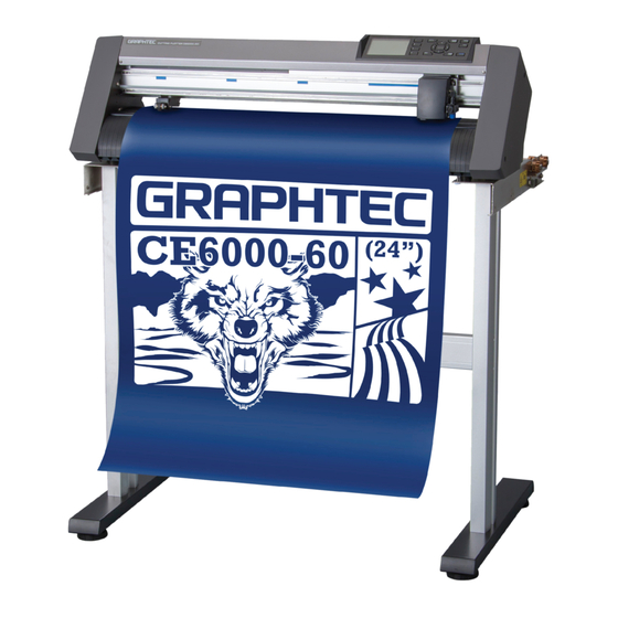
GRAPHTEC CE6000 SERIES CUTTING PLOTTER
Brand:
GRAPHTEC
| Category:
Plotter
| Size: 12 MB
Table of Contents
To Ensure Safe and Correct Use
2
Preface
6
Cutter Blades
7
Special Precautions on Handling Blades
7
After Turning on the Plotter
8
Machine Caution Label
8
Notes on the Stand
8
About the Words and Phrases in this Text
9
Selecting a Power Cable
10
Table of Contents
11
Chapter 1 Product Summary
15
Checking the Accessories
16
Nomenclature
17
Front View: CE6000-40
17
Rear View: CE6000-40
18
Front View: CE6000-60
19
Rear View: CE6000-60
20
Front View: CE6000-120
21
Rear View: CE6000-120
22
Assembling
23
Mounting the Roll-Medium Tray
28
Mounting the Stock Shafts
28
Connecting to the Computer
30
Chapter 2: Preparing to Cut
31
Preparation of Cutter Plunger
32
Cutter Plunger Nomenclature
32
Structure of Cutter Plunger
32
Adjusting the Blade Length
32
Blade Application and Features
33
Attaching a Tool
34
Removing the Tool
35
Loading Media (Paper or Marking Film)
36
Loading Roll Media (CE6000-40)
36
Loading Roll Media (CE6000-60/120)
39
Loading Sheet Media (CE6000-40/60)
44
Loading Sheet Media (CE6000-120)
46
Aligning the Push Rollers
49
Aligning the Push Roller
49
When Feeding Long-Axis Media
49
Changing the Hold-Down Force
51
About the Default Screen
52
Connecting to the Power
53
How to Use Control Panel
54
Control Keys
54
Menu Keys
54
Indicator Lamp
55
Reading the Screen (LCD)
55
Contents of Operation from Menu Screen
57
Contents of Operation from [COND/TEST] Key
58
Setting Feeding Method
59
Pre Feed of Media (Paper or Marking Film)
61
Selecting Tool Condition
62
Setting the Tool Condition
64
Setting the Speed and Force (Simple Mode)
66
Setting the Tool
68
Setting the Speed
70
Setting the Force
71
Setting the Acceleration
72
Adjust the Blade Length Manually
74
Running Cutting Tests
75
Cutting Test
75
Confirm the Results of the Cutting Test
77
Adjust the Blade Length (Automatic Height Adjust)
78
About Simple Mode
81
Chapter 3: Basic Operations
89
Raise or Lower the Tool
90
Move the Tool Carriage and Media
91
Move in Steps Manually
91
Continuously Move Manually
91
Setting of Step Movement Distance
92
Move Away the Tool Carriage
93
Change the Cutting Condition (Condition No.)
94
Reset (Revert to the Initial State When the Power was Turned On.)
94
Setting the Origin Point
95
When Coordinate Axes Rotation Are Set
96
When Coordinate Axes Are Rotated after Origin Point Is Set
96
Setting Origin Point When HP-GL Is Set
97
Setting the Cutting Direction
98
Stop Cutting
100
Pause and Resume Cutting
100
Chapter 4: Convenient Functions
102
Settings for Cutting
103
Setting Cutting Area
103
Setting Cutting Width (EXPAND)
105
Setting Length of the Page
106
Setting Mirror
108
Set the Enlarge/Shrink Scale (Scale)
109
Copy (Duplicate Cutting)
111
Panel Cutting
116
Chapter 5: ARMS
118
Advanced Registration Mark Sensing System
118
Outline of ARMS
119
Shape (Pattern) of the Registration Mark
119
Scan Range Necessary to Detect the Registration Mark
120
Positioning of the Media and the Registration Mark
121
Position of the Origin Point and the Registration Mark
122
Media that Registration Mark Cannot be Detected
123
Setting and Adjustment of ARMS
124
Setting MARK SCAN Mode and Numbers
124
Axis Adjustment (2Point Detection)
125
Axes Adjustment (4Point Detection)
126
Setting Shape (Pattern) of Registration Mark
128
Setting Registration Mark Size
129
Setting Mark Distance
131
Setting Distance Adjustment between the Registration Mark
133
When User or Standard Modes Are Selected
134
Setting Offset between the Registration Mark and Cutting Origin Points
135
Adjusting the Sensor Level
137
Manually Adjusting the Sensor Level (Threshold Value)
139
Test the Registration Mark Sensor
141
Setting Speed of the Registration Mark Scan
143
Adjusting for the Registration Mark Scan Position
144
Detect the Registration Mark for Adjustment on the Media and Enter the Value
147
Setting the Registration Mark Automatic Detection
150
Setting the Position Using ARMS
152
Adjust with 2POINTS
152
Adjust with 3POINTS
154
Adjust with 4POINTS
155
Adjust Automatically
157
Adjust Manually
158
Chapter 6: Manual Position Adjust
161
Outline of Manual Position Adjust
162
Setting of Mark Scan Mode and Number of Adjustment Marks
162
Manual Position Adjust
163
Chapter 7: Setting Regarding Cutting Quality
166
To Cut the Corner of Thick Media Sharply
167
Outline of Tangential Emulation
167
Setting the Tangential Emulation
168
Setting Length of the Overcut
169
Setting of the Initial down Force
171
Setting the Step Pass
172
Setting the Offset Angle
173
Setting the Distance Adjust
174
Setting Initial Blade Control Position Adjust
176
Settings for OFFSET FORCE
178
Setting Paper-Weight
179
Chapter 8: Settings Regarding Cutting Time
181
Sorting the Cutting Data
182
Perform Automatic Pre Feed When Cut Data Is Received
184
Perform Automatic Pre Feed When Media Is Set (Initial Feed)
186
Setting Feed Speed for Pre Feed
187
Setting the Tool up Speed
189
Setting the Tool up Move
191
Chapter 9: Setting Regarding Interface
193
Setting Interface
194
USB Interface
194
RS-232C Interface
194
Interface Setting Menu
194
Connecting with RS-232C
195
Chapter 10: Settings Regarding Operation Environment
199
Related to Menu Display
200
Related to Sensor
202
Related to Plotter Environment
204
Chapter 11: Settings of Controls from Computer
206
Related to Command Processing
207
Related to GP-GL Command
209
Related to HP-GL Command
212
Chapter 12: Maintenance
214
Daily Maintenance
215
Storing the Plotter
215
Replacing Cutter Blade
216
Cleaning the Cutter Pen
217
Cutter Plunger Exchange
218
Chapter 13: Troubleshooting
219
Troubleshooting
220
When the Plotter Does Not Operate after Turning the Power on
220
When It Does Not Work Right
221
When the Cutting Result Is Not Good
223
Error Messages in GP-GL Command Mode
224
Error Messages in HP-GL Command Mode
225
ARMS Error Messages
227
Other Error Messages
229
Caution Message
231
Printing the Setting of the Plotter
232
Creating Test Pattern
234
Confirm the Cutting Data
236
Self Diagnostic Test
238
Reading the Error Message
239
Appendix
241
Main Specifications
241
Options and Supplies
241
A.1 Main Specifications
242
A.2 Options and Supplies
243
External Dimensions
244
A.3 External Dimensions
244
Menu Tree
247
A.4 Menu Tree
247
Initial Setting
253
A.5 Initial Setting
253
Index
255
Advertisement
GRAPHTEC CE6000 SERIES Service Manual (203 pages)
CUTTING PLOTTER
Brand:
GRAPHTEC
| Category:
Plotter
| Size: 33 MB
Table of Contents
Table of Contents
4
1 Introduction
8
Main Specifications
8
External Dimensions
11
Options
13
Supplies
13
2 PARTS NAMES and FUNCTIONS
14
Parts Names and Functions (CE6000-40/60/120/120AMO)
14
Assembling the Stand (CE6000-40/60/120/120AMO)
20
Parts Names and Functions (CE6000-120AP)
27
Assembling the Stand (CE6000-120AP)
29
3 Operations
35
Control Panel
35
Menu Tree
40
4 Recommended Parts List
52
5 List of Tools
54
Tools
54
Greasing and Gluing Points
54
6 Disassembly and Reassembly
56
Exterior Parts
56
Right Side Cover
56
Left Side Cover
56
Center Cover
57
Front Guide (CE6000-40/60)
58
Front Guide (CE6000-120)
59
Rear Guide (CE6000-40/60)
60
Rear Guide (CE6000-120)
61
Mechanical Parts
62
Front Media Sensor
62
Rear Media Sensor
63
Push Roller
63
Push Roller Arm
64
Cam Sensor Board
65
Pen Block
66
Push Roller Sensor
69
Y-Relay Board
70
Control Panel Key Board
71
Lcd
73
Y-Belt
74
Y-Motor
76
Main Board
78
X-Motor for the CE6000-40/60
79
X-Motor for the CE6000-120
81
Y-Flexible Cable
84
Vacuum Fan for the CE6000-40/60
87
Vacuum Fan for the CE6000-120
88
Power Supply
89
Drive Roller Shaft
90
Cutting Mat
92
Cutting Mat Base Assembly
93
How to Confirm the y Rail Mounting Position
95
Regarding the Push Roller Position Limit Screws
97
7 Electrical Adjustments
98
DIP Switch Settings
98
List of Items Requiring Readjustment
99
Explanation of the Values of the Main Board Settings
100
Clearing the Non-Volatile RAM
101
Selecting Display Language & Length Unit
102
The Suffix Setting
103
Adjusting the Pen Force
106
Adjusting the Distance Accuracy
109
Adjusting the Registration Mark Sensor Sensitivity
114
Adjusting the Offset of the Registration Mark Sensor
116
Adjusting the RMS Sensor and the Paper Sensor Position
122
Adjusting the Tool Exchange Position (CE6000-120AP)
126
Adjusting the Offset between Tool 1 and Tool 2 (CE6000-120AP)
129
Adjusting the y Limit Position (CE6000-120AP)
132
Upgrading the System Firmware
134
8 Service Modes
136
Sensor and Key Switch Test Mode
136
Clear Setup Mode
138
Printing the Setting of the Plotter
139
Test Pattern
140
Confirm the Cutting Data
141
Self Diagnostic Test
142
9 Troubleshooting
144
The Plotter Is Turned on but Doesn't Operate
144
Media Loading Operations
145
Cutting Operations
146
Error Messages in GP-GL Command Mode
147
Error Messages in HP-GL Command Mode
148
ARMS Error Messages
150
Other Error Messages
152
Caution Message
154
Troubleshooting of Experience
155
10 Parts List
165
Outer Casing CE6000-40/60/Plus
165
Outer Casing CE6000-120/120Amo/120Plus
166
Outer Casing CE6000-120AP
167
Outer Casing CE6000-120AP (New)
168
Main Frame CE6000-40/60/Plus
169
Main Frame CE6000-120/120AMO/120 Plus/120Ap
171
Pen Block CE6000-40/60/120/120Amo/Plus
173
Pen Block CE6000-120AP
175
Control Panel
177
Wiring Harness
178
Stand CE6000-60/Plus, ST0100
179
Stand CE6000-120/120Amo/120Plus, ST0101
180
Option Basket CE6000-60/Plus
181
Option Basket CE6000-120/120Amo/120Plus
182
Stand CE6000-120AP, ST0102
183
Basket CE6000-120AP
184
Other Parts
185
11 Block Diagrams and Circuit Diagrams
186
Block Diagrams
186
Circuit Diagrams
187
12 Target Electrical Component for WEEE Instruction
196
GRAPHTEC CE6000 SERIES Setup Manual (21 pages)
Brand:
GRAPHTEC
| Category:
Plotter
| Size: 1 MB
Table of Contents
Before Starting the Setup
2
Flow of Setup
2
Attaching a Tool
3
Removing the Tool
4
Loading Media (Paper or Marking Film)
4
Loading Roll Media
4
Loading Sheet Media
7
Aligning the Push Rollers
9
About the Initial Setup Screen
10
To Make 1 Cut with Set Value
11
Adjustment of Offset
12
Installing the Software
14
Launching the Start Menu
14
Advertisement
GRAPHTEC CE6000 SERIES Replacement Manual (4 pages)
New procedure to replace the main board
Brand:
GRAPHTEC
| Category:
Plotter
| Size: 0 MB
Table of Contents
New Procedure to Replace the Main Board of CE6000
1
How to Copy the Adjustment Values from the Sub NVRAM to the Main Board
1
When the Sub NV-RAM Values Were Not Able to Copy to the Main Board
2
How to Backup the Main Board Value to the Sub-NVRAM
3
How to Create the Backup Command File
3
Procedure
3
Advertisement
Related Products
GRAPHTEC CE6000-40
GRAPHTEC CE6000-60
GRAPHTEC CE6000-120
GRAPHTEC CE6000-120AMO
GRAPHTEC CE6000-120AP
GRAPHTEC CE6000-40 Plus
GRAPHTEC CE6000-60 Plus
GRAPHTEC CE6000-120 Plus
GRAPHTEC CE8000-60
GRAPHTEC CELITE-50
GRAPHTEC Categories
Plotter
Data Loggers
Scanner
Cutter
Printer
More GRAPHTEC Manuals
Login
Sign In
OR
Sign in with Facebook
Sign in with Google
Upload manual
Upload from disk
Upload from URL