Sign In
Upload
Manuals
Brands
Emerson Manuals
Transmitter
Micro Motion 5700
Emerson Micro Motion 5700 Manuals
Manuals and User Guides for Emerson Micro Motion 5700. We have
12
Emerson Micro Motion 5700 manuals available for free PDF download: Configuration And Use Manual, Instruction Manual, Installation Manual, Installation Instructions Manual
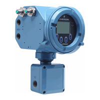
Emerson Micro Motion 5700 - Ethernet Transmitters Manual
Brand:
Emerson
| Category:
Transmitter
| Size: 1 MB
Table of Contents
Before you begin
About this document
Hazard messages
Related documentation
Planning
Installation checklist
Additional considerations for retrofitting existing installations
Power requirements
Maximum cable lengths between sensor and transmitter
5700 transmitters in Ethernet networks
Star topology
Ring topology
Daisy-chain topology
Mounting and sensor wiring
Mounting and sensor wiring for integral-mount transmitters
Mounting transmitters
Mount the transmitter to a wall or flat surface
Mount the transmitter to a pole
Wire a remote-mount transmitter to the sensor
Ground the meter components
Rotate the transmitter on the sensor (optional)
Rotate the user interface on the transmitter (optional)
Rotate the sensor wiring junction box on a remote-mount transmitter (optional)
Wiring the channels
Available channels
Wire the I/O channel
Access the wiring channels
Wire the mA Output
Wire the Frequency Output
Wire the Discrete Output
Wire the Discrete Input
Wire the I/O channel using an M12-terminated cable (optional)
Wire the Ethernet channels
Wire an Ethernet network using the RJ45 ports
Direct connection and star topology
Daisy-chain and ring topologies
Wire the Ethernet I/O using M12-terminated cables (optional)
Power supply wiring
Wiring the power supply
Wire the power supply using an M12-terminated cable (optional)
Set up the printer
Set up the printer by changing the printer default IP address
Set up the printer using the printer default IP address
Reset the interface settings
Function Check Failed
Power up the transmitter
Guided setup
Using the display controls
Available service port connection
A: Wire the 5700 to the 3100 relays
Safety messages
Documents / Resources
References
Advertisement
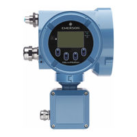
Emerson Micro Motion 5700 Configuration And Use Manual (357 pages)
Transmitters with Configurable Outputs
Brand:
Emerson
| Category:
Transmitter
| Size: 6 MB
Table of Contents
Table of Contents
3
Chapter 1 Before You Begin
7
About this Manual
7
Communications Tools and Protocols
7
Related Documents
7
Power up the Transmitter
9
Check Meter Status
9
Chapter 2 Quick Start
9
Commissioning Wizards
10
Make a Startup Connection to the Transmitter
10
Set the Transmitter Clock
10
Set the Transmitter Addresses and Tags
11
View the Licensed Features
12
Set Informational Parameters
12
Characterize the Meter (if Required)
13
Sample Sensor Tags
14
Flow Calibration Parameters (FCF, FT)
15
Density Calibration Parameters (D1, D2, K1, K2, FD, DT, TC)
15
Verify Mass Flow Measurement
16
Verify the Zero
16
Chapter 3 Introduction to Configuration and Commissioning
19
Security and Write Protection
19
USP Security
19
Lock or Unlock the Transmitter
20
Enable or Disable the Service Port
21
Set the HART Lock
22
Enable or Disable Software Write-Protection
22
Configure Security for the Display
23
Work with Configuration Files
24
Save a Configuration File Using the Display
24
Save a Configuration File Using Prolink III
25
Load a Configuration File Using the Display
27
Load a Configuration File Using Prolink III
28
Restore the Factory Configuration
29
Replicate a Transmitter Configuration
29
Chapter 4 Configure Process Measurement
31
Configure Sensor Flow Direction Arrow
31
Configure Mass Flow Measurement Unit
32
Define a Special Measurement Unit for Mass Flow
33
Configure Flow Damping
34
Configure Mass Flow Cutoff
35
Effect of Flow Damping on Volume Measurement
35
Interaction between Flow Damping and Ma Output Damping
35
Effect of Mass Flow Cutoff on Volume Measurement
36
Interaction between Mass Flow Cutoff and Ma Output Cutoff
36
Configure Volume Flow Measurement for Liquid Applications
37
Options for Volume Flow Measurement Unit for Liquid Applications
38
Define a Special Measurement Unit for Volume Flow
39
Configure Volume Flow Cutoff
40
Interaction between Volume Flow Cutoff and Mao Cutoff
40
Configure Gas Standard Volume (GSV) Flow Measurement
41
Configure Volume Flow Type for Gas Applications
41
Configure Standard Gas Density
42
Configure Gas Standard Volume Flow Measurement Unit
42
Options for Gas Standard Volume Flow Measurement Unit
43
Define a Special Measurement Unit for Gas Standard Volume Flow
43
Configure Gas Standard Volume Flow Cutoff
45
Configure Density Measurement
46
Options for Density Measurement Unit
46
Configure Density Damping
47
Configure Density Cutoff
48
Configure Temperature Measurement
48
Effect of Density Damping on Volume Measurement
48
Interaction between Density Damping and Ma Output Damping
48
Configure Temperature Damping
49
Options for Temperature Measurement Unit
49
Configure Pressure Measurement Unit
50
Effect of Temperature Damping on Process Measurement
50
Configure Velocity Measurement Unit
51
Options for Pressure Measurement Unit
51
Options for Velocity Measurement Unit
52
Chapter 5 Configure Process Measurement Applications
53
Set up the API Referral Application
53
Enable the API Referral Application Using the Display
53
Configure API Referral Using the Display
54
Set up the API Referral Application Using Prolink III
58
Configure API Referral Using Prolink III
59
Set up the API Referral Application Using the Field Communicator
63
Configure API Referral Using the Field Communicator
63
Set up Temp/Pressure Data for API Referral Using Field Communicator
65
API Tables Supported by the API Referral Application
69
Process Variables from the API Referral Application
70
Set up Concentration Measurement
71
Requirements for Matrices
71
Methods to Load a Matrix File
71
Requirements for Derived Variables
72
Derived Variables and Net Flow Rate
72
Derived Variables Based on Specific Gravity
72
Optional Tasks in Setting up Concentration Measurement
72
Set up Concentration Measurement Using the Display
73
Load a Concentration Matrix from a USB Drive Using the Display
73
Load a Concentration Matrix from the SD Card Using the Display
75
Set up Temperature Data for CM Using the Display
76
Modify Matrix Names and Labels Using the Display
78
Modify Extrapolation Alerts for Concentration Measurement
78
Select the Active Concentration Matrix Using the Display
79
Set up Concentration Measurement Using Prolink III
79
Load a Concentration Matrix Using Prolink III
80
Set Reference Temperature Values for Specific Gravity
81
Set up Temperature Data for Concentration Measurement
82
Modify Matrix Names and Labels Using Prolink III
84
Modify Extrapolation Alerts for CM Using Prolink III
84
Select the Active Concentration Matrix Using Prolink III
85
Set up Concentration Measurement Using the Field Communicator
85
Load a Concentration Matrix from the Transmitter's SD Card
86
Provide Temperature Data for Concentration Measurement
87
Modify Matrix Names and Labels Using the Field Communicator
90
Select the Active Concentration Matrix Using the Field Communicator
90
Configure the Batching Application
91
Configure Global Batching Parameters Using the Display
91
Configure Global Batching Parameters Using Prolink III
92
Configure Global Batching Parameters Using the Field Communicator
94
Configure Batch Resets
95
Configure Batch Presets Using the Display
95
Configure Batch Presets Using Prolink III
96
Configure Batch Presets Using the Field Communicator
97
Configure a DO for Valve Control Using the Display
98
Configure a DO for Valve Control Using Prolink III
99
Configure a DO for Valve Control Using the Field Communicator
100
Configure AOC Using the Display
101
Configure AOC Using Prolink III
102
Configure AOC Using the Field Communicator
102
Chapter 6 Configure Advanced Options for Process Measurement
105
Configure Response Time
105
Detect and Report Two-Phase Flow
105
Detect Two-Phase Flow Using Sensor Diagnostics
106
Configure Flow Rate Switch
107
Configure Events
108
Configure a Basic Event
108
Configure an Enhanced Event
109
Configure Totalizers and Inventories
110
Options for Enhanced Event Action
110
Default Settings for Totalizers and Inventories
113
Configure Logging for Totalizers and Inventories
113
Configure Process Variable Fault Action
114
Options for Process Variable Fault Action
115
Chapter 7 Configure Device Options and Preferences
119
Configure the Transmitter Display
119
Configure the Language Used on the Display
119
Configure the Process Variables Shown on the Display
119
Configure the Number of Decimal Places Shown on the Display
120
Configure a Two-Line Display Screen
120
Default Configuration for Display Variables
120
Turn on and Turn off Automatic Scrolling through the Display Variables
121
Configure the Display Backlight
122
Configure Totalizer and Inventory Control
124
Configure the Transmitter's Response to Alerts
125
Configure Fault Timeout
128
Alerts, Conditions, and Configuration Options
129
Configuration Error
129
Configuration Warning
129
Core Low Power
129
Drive over Range
130
Electronics Failed
130
Event Active
130
Extreme Primary Purpose Variable
130
Function Check Failed or Smart Meter Verification Aborted
131
Function Check in Progress
131
Output Fixed
131
Output Saturated
132
Process Aberration
132
Security Breach
133
Sensor Being Simulated
133
Sensor Failed
133
Sensor-Transmitter Communication Error
133
Tube Not Full
134
Chapter 8 Integrate the Meter with the Control System
135
Configure the Transmitter Channels
135
Configure an Ma Output
137
Configure Ma Output Source
137
Options for Ma Output Source
138
Configure Lower Range Value and Upper Range Value for the Ma Output
139
Configure Ma Output Direction
140
Effect of Ma Output Direction on an Ma Output
141
Configure Ma Output Cutoff
143
Configure Ma Output Damping
144
Interaction between Ma Output Cutoff and Process Variable Cutoffs
144
Configure Ma Output Fault Action
145
Interaction between Ma Output Damping and Process Variable Damping
145
Options for Mao Fault Action and Mao Fault Level
146
Configure the Ma Input
147
Configure Ma Input Assignment
147
Configure Lower Range Value and Upper Range Value for the Ma Input
148
Configure Ma Input Damping
148
Configure Frequency Output Source
149
Options for Frequency Output Source
150
Configure Frequency Output Scaling
151
Calculate Frequency from Flow Rate
151
Configure Frequency Output Direction
152
Configure Frequency Output Mode (Dual-Pulse Mode)
153
Configure Frequency Output Fault Action
154
Options for Frequency Output Mode
154
Configure the Frequency Input
155
Options for Frequency Output Fault Action
155
Configure Frequency Input Assignment
156
Configure Frequency Input Scaling
156
Configure the K Factor
157
Configure a Discrete Output
158
Options for Discrete Output Source
159
Configure Discrete Output Polarity
160
Configure Discrete Output Fault Action
161
Configure Discrete Input Action
162
Configure Discrete Input Polarity
163
Chapter 9 Configure Digital Communications
165
Configure HART Communications
165
Configure HART Variables (PV, SV, TV, QV)
166
Options for HART Variables
166
Configure Burst Communications
168
Configure HART Burst Messages
168
Configure HART Trigger Mode
169
Configure HART Event Notification
170
Configure Modbus Communications
171
Bit Structure of Double-Precision Bytes
173
Chapter 10 Configure, Wire, and Use a Printer for Tickets
175
Ticket Types
175
Wire the Printer
176
Configure the Printer
177
Ticket and Heading Parameters
178
Batch Ticket Configurable Parameters
178
Transfer Ticket Configurable Parameters
178
Configure a Discrete Input or Discrete Event
179
Header Lines
179
Print a Batch Ticket
180
Print a Standard Ticket
180
Batch Ticket Contents
181
Print a Transfer Ticket
182
Transfer Ticket Contents
182
MMI-20025166 March
183
Chapter 11 Complete the Configuration
185
Test or Tune the System Using Sensor Simulation
185
Sensor Simulation
186
Save the Transmitter Configuration to a Backup File
187
Enable or Disable Software Write-Protection
187
View Process and Diagnostic Variables
189
Chapter 12 Transmitter Operation
189
View and Acknowledge Status Alerts
190
Effect of Sensor Flow Direction Arrow on Digital Communications
190
Read Totalizer and Inventory Values
191
Start, Stop, and Reset Totalizers and Inventories
192
Chapter 13 Operation Using the Batcher
195
Run a Batch
195
Perform AOC Calibration
197
Use Smart Meter Verification (SMV)
199
Run an SMV Test
199
Chapter 14 Measurement Support
199
View SMV Test Results
202
Understanding SMV Results
203
Set up SMV Automatic Execution
204
Production Volume Reconciliation (PVR)
206
Transient Bubble Remediation (TBR)
206
Transient Mist Remediation (TMR)
206
Use PVR, TBR, and TMR
206
Zero the Meter
207
Terminology Used with Zero Verification and Zero Calibration
208
Set up Pressure Compensation
209
Set up Pressure Compensation Using the Display
210
Set up Pressure Compensation Using Prolink III
212
Configure Pressure Compensation Using the Field Communicator
214
Validate the Meter
216
Alternate Method for Calculating the Meter Factor for Volume Flow
217
Perform a (Standard) D1 and D2 Density Calibration
218
Perform a D1 and D2 Density Calibration Using Prolink III
219
Perform a D1 and D2 Density Calibration Using the Field Communicator
220
Adjust Concentration Measurement with Trim Offset
221
Adjust Concentration Measurement with Trim Slope and Trim Offset
222
Set up Energy Flow
224
Configure PWL
225
Piecewise Linearization (PWL) for Calibrating Gas Meters
225
Install a New Transmitter License
227
Chapter 15 Maintenance
227
Upgrade the Transmitter Firmware
228
Using a USB Drive with the Display
228
Reboot the Transmitter
229
Using the USB Service Port and Prolink III
229
Battery Replacement
230
Chapter 16 Log Files, History Files, and Service Files
231
Generate History Files
231
Historian Data and Log
232
SMV History and SMV Log
234
Totalizer History and Log
235
Read Contract Totals
236
Generate Service Files
237
Configure Contract Totals into the Totalizer History Log
237
Alert History and Log
238
Configuration Audit History and Log
240
Assert History and Log
242
Security Log
242
Status LED and Device Status
245
API Referral Problems
245
Extrapolation Alert Is Active/Inaccurate Referred Density Reading
245
Chapter 17 Troubleshooting
245
Batch Problems
246
Batch will Not Start
246
Valve Does Not Operate
246
Valve Operation Is Backwards
246
Concentration Measurement Problems
247
Significantly Incorrect CM after Loading Matrix
247
Ts Batchrepeatnotsatis
247
Density Measurement Problems
248
Erratic Density Reading
248
Inaccurate CM Reading
248
Inaccurate Density Reading
249
Unusually High Density Reading
249
Discrete Input Problems
250
No Discrete Input
250
Unusually Low Density Reading
250
Discrete Output Problems
251
Loop Test Failed
251
No Discrete Output
251
Discrete Output Readings Reversed
252
Erratic Non-Zero Flow Rate at No-Flow Conditions
252
Flow Indication at no Flow Conditions or Zero Offset
252
Flow Measurement Problems
252
Erratic Non-Zero Flow Rate When Flow Is Steady
253
Inaccurate Flow Rate
254
Frequency Input Problems
255
Frequency Output Problems
255
No FO
255
Consistently Incorrect FO Measurement
256
Erratic FO
257
FO Goes in and out of Fault Conditions
257
Ma Input Problems
257
Ma Input Value Consistently Wrong
257
Ma Input Value Slightly Inaccurate
258
Milliamp Output Problems
258
No Mao
258
Constant Mao
259
Mao below 4 Ma
259
Consistently Incorrect Ma Measurement
260
Mao Consistently out of Range
260
Mao Correct at Lower Current, but Incorrect at Higher Current
261
Mao Goes in and out of Fault Conditions
261
Status Alerts, Causes, and Recommendations
261
[002] RAM Error (Core Processor)
261
[003] Sensor Failed
262
[005] Mass Flow Rate Overrange
262
[008] Density Overrange
263
[009] Transmitter Initializing/ Warming up
263
[010] Calibration Failed
263
[016] Sensor Temperature (RTD) Failure
264
[017] Sensor Case Temperature (RTD) Failure
264
[018] EEPROM Error (Transmitter)
265
[019] RAM Error (Transmitter)
265
[020] Calibration Factors Missing
266
[021] Incorrect Sensor Type
266
[022] Configuration Database Corrupt
267
[024] Program Corrupt (Core Processor)
267
[026] Sensor/Transmitter Communications Failure
268
[028] Core Process Write Failure
268
[030] Incorrect Board Type
268
[031] Low Power
269
[033] Insufficient Pickoff Signal
269
[034] Smart Meter Verification Failed
270
[035] Smart Meter Verification Aborted
270
[100] Ma Output 1 Saturated
270
[101] Ma Output 1 Fixed
270
[102] Drive Overrange
271
[103] Configuration Warning
271
[104] Calibration in Progress
272
[105] Two-Phase Flow
272
[110] Frequency Output X Saturated
272
[111] Frequency Output 1 Fixed
273
[113] Ma Output 2 Saturated
273
[114] Ma Output 2 Fixed
273
[115] External Input Error
273
[116] Temperature Overrange (API Referral)
274
[117] Density Overrange (API Referral)
274
[118] Discrete Output 1 Fixed
274
[119] Discrete Output 2 Fixed
275
[120] Curve Fit Failure (Concentration)
275
[121] Extrapolation Alert (Concentration)
275
[122] Discrete Output 3 Fixed
275
[123] Pressure Overrange (API Referral)
276
[131] Smart Meter Verification in Progress
276
[132] Sensor Simulation Active
276
[138] TBR Active
276
Batch Time out
277
Batcher Not Configured
277
Clock Failure
277
Core Processor Update Failed
277
Enhanced Event X Active
278
Event X Active
278
Frequency Input Saturated
278
Frequency Output 2 Fixed
279
Frequency Output 2 Saturated
279
Ma Input Failure or Outside Range
279
Ma Output 3 Fixed
280
Ma Output 3 Saturated
280
Moderate Two Phase Flow
280
No Permanent License
280
Paper out
281
Password Not Set
281
SD Card Failure
281
SD Card Full
282
Severe Two Phase Flow
282
Time Not Entered
282
Transmitter Software Update Failed
282
Perform a Core Processor Resistance Test
283
Verification of Ma Output 1 Failed
283
Watchdog Error
283
Core Processor Terminals Inside the Transmitter Junction Box
284
Removing the Cover of the Junction Box
284
Check Batch Total against Scale Reading
285
Check the Cutoffs
286
Check the Direction Parameters
286
Check the Drive Gain
286
Check for Internal Electrical Problems
287
Check Frequency Output Fault Action
287
Check Frequency Output Mode
288
Check HART Burst Mode
288
Check HART Communications
288
Check the Scaling of the Frequency Output
288
Locate a Device Using the HART 7 Squawk Feature
290
Wiring and Power to Test Terminals
290
Check Grounding
291
Perform Loop Tests Using the Display
291
Perform Loop Tests Using Prolink III
293
Perform Loop Tests Using the Field Communicator
295
Check Lower Range Value and Upper Range Value
297
Check Ma Output Fault Action
297
Trim an Ma Output Using the Display
298
Trim Ma Output Using Prolink III
298
Check the Pickoff Voltage
299
Trim Ma Outputs Using the Field Communicator
299
Check for Radio Frequency Interference (RFI)
300
Check Power Supply Wiring
300
Check the Sensor Coils
301
Check the Printing
303
Using Sensor Simulation for Troubleshooting
303
Check for Two-Phase Flow (Slug Flow)
304
Temperature Measurement Problems
304
Velocity Measurement Problems
305
Emerson Micro Motion 5700 Configuration And Use Manual (286 pages)
Model 5700 with Ethernet
Brand:
Emerson
| Category:
Transmitter
| Size: 6 MB
Table of Contents
Table of Contents
3
Part I Getting Started
9
Chapter 1 Before You Begin
11
About this Manual
11
Communication Methods
11
Additional Documentation and Resources
12
Chapter 2 Quick Start
13
Power up the Transmitter
13
Check Meter Status
14
Commissioning Wizards
14
Make a Startup Connection to the Transmitter
14
Set the Transmitter Clock
15
View the Licensed Features
16
Set Informational Parameters
16
Characterize the Meter (if Required)
17
Sample Sensor Tags
19
Flow Calibration Parameters (FCF, FT)
19
Density Calibration Parameters (D1, D2, K1, K2, FD, DT, TC)
20
Verify Mass Flow Measurement
21
Verify the Zero
21
Part II Configuration and Commissioning
23
Chapter 3 Introduction to Configuration and Commissioning
25
Security and Write Protection
25
Lock or Unlock the Transmitter
25
Enable or Disable the Service Port
27
Enable or Disable Software Write-Protection
28
Configure Security for the Display
28
Work with Configuration Files
29
Save a Configuration File Using the Display
29
Save a Configuration File Using Prolink III
31
Load a Configuration File Using the Display
32
Load a Configuration File Using Prolink III
33
Restore the Factory Configuration
35
Replicate a Transmitter Configuration
35
Chapter 4 Configure Process Measurement
37
Configure Sensor Flow Direction Arrow
37
Configure Mass Flow Measurement
39
Configure Mass Flow Measurement Unit
39
Configure Flow Damping
41
Configure Mass Flow Cutoff
42
Configure Volume Flow Measurement for Liquid Applications
44
Configure Volume Flow Type for Liquid Applications
44
Configure Volume Flow Measurement Unit for Liquid Applications
45
Configure Volume Flow Cutoff
48
Configure Gas Standard Volume (GSV) Flow Measurement
49
Configure Volume Flow Type for Gas Applications
50
Configure Standard Gas Density
50
Configure Gas Standard Volume Flow Measurement Unit
51
Configure Gas Standard Volume Flow Cutoff
53
Configure Density Measurement
55
Configure Density Measurement Unit
55
Configure Density Damping
56
Configure Density Cutoff
57
Configure Temperature Measurement
58
Configure Temperature Measurement Unit
58
Configure Temperature Damping
59
Configure Pressure Measurement Unit
60
Options for Pressure Measurement Unit
61
Configure Velocity Measurement Unit
61
Options for Velocity Measurement Unit
62
Chapter 5 Configure Process Measurement Applications
63
Set up the API Referral Application
63
Set up the API Referral Application Using the Display
63
The Display
65
Set up the API Referral Application Using Prolink III
66
API Tables Supported by the API Referral Application
69
Process Variables from the API Referral Application
71
Set up Concentration Measurement
71
Preparing to Set up Concentration Measurement
71
Set up Concentration Measurement Using the Display
74
Set up Concentration Measurement Using Prolink III
79
Set up Concentration Measurement Using a Web Browser
85
Chapter 6 Configure Advanced Options for Process Measurement
91
Configure Response Time
91
Detect and Report Two-Phase Flow
92
Detect Two-Phase Flow Using Density
92
Detect Two-Phase Flow Using Sensor Diagnostics
93
Configure Flow Rate Switch
94
Configure Events
95
Configure a Basic Event
95
Configure an Enhanced Event
96
Configure Totalizers and Inventories
98
Default Settings for Totalizers and Inventories
101
Configure Logging for Totalizers and Inventories
101
Configure Process Variable Fault Action
102
Options for Process Variable Fault Action
103
Interaction between Process Variable Fault Action and Other Fault Actions
104
Chapter 7 Configure Device Options and Preferences
107
Configure the Transmitter Display
107
Configure the Language Used on the Display
107
Configure the Process Variables Shown on the Display
108
Configure the Number of Decimal Places (Precision) Shown on the Display
109
Turn on and Turn off Automatic Scrolling through the Display Variables
110
Configure the Display Backlight
111
Configure Totalizer and Inventory Control from the Display
111
Configure Security for the Display
112
Configure the Transmitter's Response to Alerts
113
Configure the Transmitter's Response to Alerts Using the Display
113
Configure the Transmitter's Response to Alerts Using Prolink III
114
Configure Fault Timeout
116
Alerts, Conditions, and Configuration Options
117
Chapter 8 Integrate the Meter with the Control System
125
Channel Configuration
125
Configure Ethernet Channel a and Channel B
125
Configure I/O Channel C
126
Configure the Ma Output
126
Configure Ma Output Source
127
Configure Lower Range Value (LRV) and Upper Range Value (URV) for the Ma Output
129
Configure Ma Output Direction
130
Configure Ma Output Cutoff
133
Configure Ma Output Damping
134
Configure Ma Output Fault Action
135
Configure the Frequency Output
136
Configure Frequency Output Source
137
Configure Frequency Output Scaling
138
Configure Frequency Output Direction
140
Configure Frequency Output Fault Action
141
Configure the Discrete Output
142
Configure Discrete Output Source
142
Configure Discrete Output Polarity
144
Configure Discrete Output Fault Action
145
Configure the Discrete Input
146
Configure Discrete Input Action
146
Configure Discrete Input Polarity
147
Chapter 9 Complete the Configuration
149
Test or Tune the System Using Sensor Simulation
149
Sensor Simulation
150
Save the Transmitter Configuration to a Backup File
151
Enable or Disable Software Write-Protection
151
Part III Operations, Maintenance, and Troubleshooting
153
Chapter 10 Transmitter Operation
155
View Process and Diagnostic Variables
155
View Process and Diagnostic Variables Using the Display
155
View Process Variables and Other Data Using Prolink III
155
View Process Variables and Other Data Using a Web Browser
156
Effect of Sensor Flow Direction Arrow on Digital Communications
156
View and Acknowledge Status Alerts
157
View and Acknowledge Alerts Using the Display
157
View and Acknowledge Alerts Using Prolink III
158
View Alerts Using a Web Browser
158
Read Totalizer and Inventory Values
159
Start, Stop, and Reset Totalizers and Inventories
159
Start, Stop, and Reset Totalizers Using the Display
159
Start, Stop, and Reset Totalizers Using Prolink III
160
Start, Stop, and Reset Totalizers Using a Web Browser
161
Chapter 11 Operation Using the Batcher
163
Run a Batch
163
Perform AOC Calibration
165
Perform AOC Calibration Using the Display
165
Perform AOC Calibration Using Prolink III
166
Perform AOC Calibration Using a Web Browser
167
Chapter 12 Measurement Support
169
Use Smart Meter Verification (SMV)
169
Run an SMV Test
169
View SMV Test Results
172
Set up SMV Automatic Execution
175
Zero the Meter
177
Terminology Used with Zero Verification and Zero Calibration
178
Set up Pressure Compensation
179
Set up Pressure Compensation Using the Display
180
Set up Pressure Compensation Using Prolink III
181
Set up Pressure Compensation Using a Web Browser
182
Validate the Meter
184
Alternate Method for Calculating the Meter Factor for Volume Flow
186
Perform a (Standard) D1 and D2 Density Calibration
187
Perform a D1 and D2 Density Calibration Using the Display
187
Perform a D1 and D2 Density Calibration Using Prolink III
188
Perform a D1 and D2 Density Calibration Using a Web Browser
189
Adjust Concentration Measurement with Trim Offset
189
Adjust Concentration Measurement with Trim Slope and Trim Offset
190
Chapter 13 Maintenance
193
Install a New Transmitter License
193
Upgrade the Transmitter Firmware
195
Upgrade the Transmitter Firmware Using the Display
195
Upgrade the Transmitter Firmware Using Prolink III
196
Reboot the Transmitter
196
Battery Replacement
197
Chapter 14 Log Files, History Files, and Service Files
199
Generate History Log Files
199
Historian Data and Log
200
SMV History and SMV Log
202
Totalizer History and Log
203
Generate Service Files
204
Alert History and Log
206
Configuration Audit History and Log
207
Assert History and Log
209
Security Log
209
Advertisement
Emerson Micro Motion 5700 Instruction Manual (58 pages)
Transmitters with Configurable Inputs and Outputs
Brand:
Emerson
| Category:
Transmitter
| Size: 5 MB
Table of Contents
Table of Contents
3
About this Document
5
Before You Begin
5
Hazard Messages
5
Related Documentation
5
Chapter 2 Planning
7
Installation Checklist
7
Additional Considerations for Retrofitting Existing Installations
8
Power Requirements
9
Mounting and Sensor Wiring
11
Mounting and Sensor Wiring for Integral-Mount Transmitters
11
Mounting Transmitters
11
Wire a Remote-Mount Transmitter to the Sensor
16
Ground the Meter Components
18
Rotate the Transmitter on the Sensor (Optional)
20
Rotate the User Interface on the Transmitter (Optional)
22
Rotate the Sensor Wiring Junction Box on a Remote-Mount Transmitter (Optional)
23
Wiring the Channels
25
Available Channels
25
Access the Wiring Channels
26
Wire the Ma Output
27
Wire the Ma/Hart ® Output
28
Wire the Frequency Output
31
Wire the Discrete Output
34
Wire the RS-485 Output
37
Wire the Ma Input
37
Wire the Discrete Input
38
Wire the Frequency Input
39
Wire Channels a and D for Safety Instrumented Systems (SIS) Applications
40
Wiring the Power Supply
45
Wire the Printer
47
Power up the Transmitter
49
Configuring the Transmitter with Guided Setup
51
Using the Display Controls
53
Available Service Port Connection
55
Appendix A Wire the Micro Motion 5700 to the Micro Motion 3100 Transmitter
57
Emerson Micro Motion 5700 Installation Manual (56 pages)
With Configurable Outputs, All Installation Types Integral, 4-Wire, and 9-Wire
Brand:
Emerson
| Category:
Transmitter
| Size: 5 MB
Table of Contents
Table of Contents
3
Chapter 1 Before You Begin
5
About this Document
5
Hazard Messages
5
Related Documentation
5
Chapter 2 Planning
7
Installation Checklist
7
Additional Considerations for Retrofitting Existing Installations
8
Power Requirements
9
Chapter 3 Mounting and Sensor Wiring
11
Mounting and Sensor Wiring for Integral-Mount Transmitters
11
Mounting Transmitters
11
Wire a Remote-Mount Transmitter to the Sensor
15
Ground the Meter Components
18
Rotate the Transmitter on the Sensor (Optional)
19
Rotate the User Interface on the Transmitter (Optional)
20
Rotate the Sensor Wiring Junction Box on a Remote-Mount Transmitter (Optional)
21
Chapter 4 Wiring the Channels
23
Available Channels
23
Access the Wiring Channels
23
Wire the Ma Output
24
Wire the Ma/Hart Output
26
Wire the Frequency Output
28
Wire the Discrete Output
32
Wire the RS-485 Output
35
Wire the Ma Input
35
Wire the Discrete Input
36
Wire the Frequency Input
37
Wire Channels a and D for SIS Applications
38
Chapter 5 Wiring the Power Supply
43
Chapter 6 Wire the Printer
45
Chapter 7 Power up the Transmitter
47
Chapter 8 Configuring the Transmitter with Guided Setup
49
Chapter 9 Using the Display Controls
51
Chapter 10 Available Service Port Connection
53
Appendix A 5700 to 3100 Transmitter Connections
55
Emerson Micro Motion 5700 Installation Manual (56 pages)
Ethernet Transmitters
Brand:
Emerson
| Category:
Transmitter
| Size: 8 MB
Table of Contents
Table of Contents
3
Chapter 1 Before You Begin
5
About this Document
5
Hazard Messages
5
Related Documentation
5
Chapter 2 Planning
7
Installation Checklist
7
Additional Considerations for Retrofitting Existing Installations
8
Power Requirements
9
5700 Transmitters in Ethernet Networks
10
Chapter 3 Mounting and Sensor Wiring
15
Mounting and Sensor Wiring for Integral-Mount Transmitters
15
Mounting Transmitters
15
Wire a Remote-Mount Transmitter to the Sensor
19
Ground the Meter Components
22
Rotate the Transmitter on the Sensor (Optional)
23
Rotate the User Interface on the Transmitter (Optional)
25
Rotate the Sensor Wiring Junction Box on a Remote-Mount Transmitter (Optional)
26
Chapter 4 Wiring the Channels
29
Available Channels
29
Wire the I/O Channel
29
Wire the Ethernet Channels
36
Chapter 5 Power Supply Wiring
39
Wiring the Power Supply
39
Wire the Power Supply Using an M12-Terminated Cable (Optional)
40
Chapter 6 Set up the Printer
41
Set up the Printer by Changing the Printer Default IP Address
41
Set up the Printer Using the Printer Default IP Address
43
Reset the Interface Settings
44
Function Check Failed
45
Chapter 7 Power up the Transmitter
47
Chapter 8 Guided Setup
49
Chapter 9 Using the Display Controls
51
Chapter 10 Available Service Port Connection
53
Appendix A 5700 to 3100 Transmitter Connections
55
Emerson Micro Motion 5700 Installation Manual (54 pages)
Ethernet Transmitter
Brand:
Emerson
| Category:
Transmitter
| Size: 14 MB
Table of Contents
Table of Contents
3
Chapter 1 Planning
5
About this Document
5
Related Documentation
5
Installation Checklist
6
Additional Considerations for Retrofitting Existing Installations
7
Power Requirements
8
Model 5700 Transmitters in Ethernet Networks
9
Chapter 2 Mounting and Sensor Wiring
12
Mounting and Sensor Wiring for Integral-Mount Transmitters
12
Mount the 4-Wire or 9-Wire Remote-Mount Transmitters
12
Wire the 4-Wire or 9-Wire Remote-Mount Transmitter to the Sensor
16
Ground the Meter Components
20
Rotate the Transmitter on the Sensor (Optional)
23
Rotate the User Interface on the Transmitter (Optional)
26
Rotate the Sensor Wiring Junction Box on a Remote-Mount Transmitter (Optional)
28
Chapter 3 Wiring the Channels
32
Wire the I/O Channel
32
Wire the Ethernet Channels
40
Chapter 4 Power Supply Wiring
44
Wiring the Power Supply
44
Wire the Power Supply Using an M12-Terminated Cable (Optional)
45
Chapter 5 Power up the Transmitter
47
Chapter 6 Guided Setup
48
Chapter 7 Using the Display Controls
49
Chapter 8 Available Service Port Connection
53
Emerson Micro Motion 5700 Installation Manual (46 pages)
Transmitters with Intrinsically Safe Outputs
Brand:
Emerson
| Category:
Transmitter
| Size: 5 MB
Table of Contents
Table of Contents
3
About this Document
5
Before You Begin
5
Hazard Messages
5
Related Documents
6
Chapter 2 Planning
7
Installation Checklist
7
Power Requirements
8
Mounting and Sensor Wiring
11
Mounting and Sensor Wiring for Integral-Mount Transmitters
11
Mounting Transmitters
11
Wire a Remote-Mount Transmitter to the Sensor
15
Ground the Meter Components
18
Rotate the Transmitter on the Sensor (Optional)
19
Rotate the User Interface on the Transmitter (Optional)
21
Rotate the Sensor Wiring Junction Box on a Remote-Mount Transmitter (Optional)
22
Wiring the Channels
25
Installation Types for the 5700 Transmitter
25
Available Channels
25
Barriers Verified by Micro Motion
26
Ma Power Requirements
26
FO and DO Power Requirements
28
Access the Wiring Channels
29
Wire the Channel a Ma/Hart Output
30
Wire the Channel B and C Ma Output
31
Wire the Ma/Sil Output
32
Wire the Ma/Hart Multidrop Installation
32
Wire the Frequency Output or the Discrete Output
33
Wiring the Power Supply
35
Power up the Transmitter
37
Configuring the Transmitter with Guided Setup
39
Using the Display Controls
41
Available Service Port Connection
43
Appendix A Wire the Micro Motion 5700 to the Micro Motion 3100 Transmitter
45
Emerson Micro Motion 5700 Installation Manual (46 pages)
Brand:
Emerson
| Category:
Transmitter
| Size: 6 MB
Table of Contents
Table of Contents
3
About this Document
5
Chapter 1 Before You Begin
5
Hazard Messages
5
Related Documentation
6
Chapter 2 Planning
7
Installation Checklist
7
Additional Considerations for Retrofitting Existing Installations
8
Power Requirements
8
Chapter 3 Mounting and Sensor Wiring
11
Mounting and Sensor Wiring for Integral-Mount Transmitters
11
Mounting Transmitters
11
Wire a Remote-Mount Transmitter to the Sensor
15
Ground the Meter Components
17
Rotate the Transmitter on the Sensor (Optional)
18
Rotate the User Interface on the Transmitter (Optional)
20
Rotate the Sensor Wiring Junction Box on a Remote-Mount Transmitter (Optional)
21
Chapter 4 Wiring the Channels
23
Installation Types for the 5700 Transmitter
23
Available Channels
23
Access the Wiring Channels
24
I/O Wiring
25
FISCO-Input Entity Parameters
26
Wiring for Nonhazardous Installations
27
Wiring for Hazardous Installations
30
Chapter 5 Wiring the Power Supply
35
Chapter 6 Setting the 5700 for PROFIBUS-PA Communication
37
Addressing
37
Chapter 7 Power up the Transmitter
39
Chapter 8 Guided Setup
41
Chapter 9 Using the Display Controls
43
Chapter 10 Available Service Port Connection
45
Emerson Micro Motion 5700 Installation Manual (44 pages)
Intrinsically Safe Outputs. All Installation Types (Integral, 4-Wire, and 9-Wire)
Brand:
Emerson
| Category:
Transmitter
| Size: 4 MB
Table of Contents
Table of Contents
3
Chapter 1 Before You Begin
5
About this Document
5
Related Documents
5
Chapter 2 Planning
7
Installation Checklist
7
Power Requirements
8
Chapter 3 Mounting and Sensor Wiring
11
Mounting and Sensor Wiring for Integral-Mount Transmitters
11
Mount the Transmitter to a Wall or Instrument Pole
11
Wire a Remote-Mount Transmitter to the Sensor
14
Ground the Meter Components
17
Rotate the Transmitter on the Sensor (Optional)
17
Rotate the User Interface on the Transmitter (Optional)
20
Rotate the Sensor Wiring Junction Box on a Remote-Mount Transmitter (Optional)
21
Chapter 4 Wiring the Channels
23
Installation Types for the 5700 Transmitter
23
Available Channels
23
Barriers Verified by Micro Motion
24
Ma Power Requirements
24
FO and DO Power Requirements
26
Access the Wiring Channels
28
Wire the Channel a Ma/Hart Output
30
Wire the Channel B and C Ma Output
31
Wire the Ma/Sil Output
32
Wire the Ma/Hart Multidrop Installation
32
Wire the Frequency Output or the Discrete Output
33
Chapter 5 Wiring the Power Supply
35
Chapter 6 Power up the Transmitter
37
Chapter 7 Configuring the Transmitter with Guided Setup
39
Chapter 8 Using the Display Controls
41
Chapter 9 Available Service Port Connection
43
Emerson Micro Motion 5700 Installation Manual (54 pages)
Brand:
Emerson
| Category:
Transmitter
| Size: 4 MB
Table of Contents
Table of Contents
2
Planning
3
Power Requirements
5
Mounting and Sensor Wiring
7
Wiring the Channels
25
Wiring the Power Supply
45
Power up the Transmitter
47
Configuring the Transmitter with Guided Setup
48
Using the Display Controls
49
Available Service Port Connection
53
Emerson Micro Motion 5700 Installation Instructions Manual (12 pages)
ATEX Zone 2/22 II 3 G or II 3 (2) G/EPL Gc & II 3 D/EPL Dc
Brand:
Emerson
| Category:
Transmitter
| Size: 0 MB
Advertisement
Related Products
Emerson Rosemount 5081-T
Emerson 5301HxxxxxxxxxxxxxxZZ Series
Emerson 5303HxxxxxxxxxxxxxxZZ Series
Emerson Rosemount 5302
Emerson Rosemount 5301
Emerson ROSEMOUNT 5081-A
Emerson Rosemount Analytical HART 5081-A-HT
Emerson Rosemount 550PT
Emerson Rosemount 551
Emerson Micro Motion Transmitters and Discrete Controllers Series 3000
Emerson Categories
Controller
Control Unit
Transmitter
Measuring Instruments
Fan
More Emerson Manuals
Login
Sign In
OR
Sign in with Facebook
Sign in with Google
Upload manual
Upload from disk
Upload from URL