Emerson Micro Motion 5700 Installation Manual
Hide thumbs
Also See for Micro Motion 5700:
- Installation manual ,
- Configuration and use manual (357 pages) ,
- Instruction manual (58 pages)

Related Manuals for Emerson Micro Motion 5700


Summary of Contents for Emerson Micro Motion 5700
- Page 1 Installation Manual MMI-20075112, Rev AA August 2020 ™ Micro Motion 5700 Transmitters ® Installation Manual for PROFIBUS...
- Page 2 Micro Motion employees. Micro Motion will not accept your returned equipment if you fail to follow Micro Motion procedures. Return procedures and forms are available on our web support site at www.emerson.com, or by phoning the Micro Motion Customer Service department.
-
Page 3: Table Of Contents
Installation Manual Contents MMI-20075112 August 2020 Contents Chapter 1 Before you begin......................5 1.1 About this document........................5 1.2 Hazard messages......................... 5 1.3 Related documentation....................... 6 Chapter 2 Planning........................7 2.1 Installation checklist........................7 2.2 Additional considerations for retrofitting existing installations............ 8 2.3 Power requirements........................ - Page 4 Contents Installation Manual August 2020 MMI-20075112 Micro Motion 5700 transmitters for PROFIBUS PA...
-
Page 5: Before You Begin
Installation Manual Before you begin MMI-20075112 August 2020 1 Before you begin 1.1 About this document This manual provides information on planning, mounting, wiring, and initial setup of the 5700 PROFIBUS-PA transmitter. For information on full configuration, maintenance, troubleshooting, or service of the transmitter, see the configuration and use manual. -
Page 6: Related Documentation
See any of the following documents for more information: • Micro Motion 5700 Product Data Sheet • Micro Motion 5700 Transmitters for PROFIBUS-PA: Configuration and Use Manual • PROFIBUS-PA User and Installation Guideline • Sensor installation manual Micro Motion 5700 transmitters for PROFIBUS PA... -
Page 7: Chapter 2 Planning
For ATEX/IECEx installations, strictly adhere to the safety instructions documented in the ATEX/IECEx approvals documentation available on the product documentation DVD shipped with the product or at www.emerson.com. □ Verify that you have the appropriate cable and required cable installation parts for your installation. For wiring between the transmitter and sensor, verify the maximum cable length does not exceed 1,000 ft (305 m). -
Page 8: Additional Considerations For Retrofitting Existing Installations
2.3 Power requirements Self-switching AC/DC input, automatically recognizes supply voltage: • 85 to 240 VAC, 50/60 Hz, 6 watts typical, 11 watts maximum • 18 to 100 VDC, 6 watts typical, 11 watts maximum Micro Motion 5700 transmitters for PROFIBUS PA... - Page 9 Installation Manual Planning MMI-20075112 August 2020 Note For DC power: • Power requirements assume a single transmitter per cable. • At startup, the power source must provide a minimum of 1.5 amps of short-term current per transmitter and not pull voltage below 18 VDC. •...
- Page 10 Wire gauge Maximum length VDC 20 AWG (0.518 mm²) 500 ft (152 m) VDC 18 AWG (0.823 mm²) 1,000 ft (305 m) RS-485 22 AWG (0.326 mm²) or larger 1,000 ft (305 m) Micro Motion 5700 transmitters for PROFIBUS PA...
-
Page 11: Mounting And Sensor Wiring
Installation Manual Mounting and sensor wiring MMI-20075112 August 2020 3 Mounting and sensor wiring 3.1 Mounting and sensor wiring for integral-mount transmitters There are no separate mounting requirements for integral transmitters, and no need to connect wiring between the transmitter and the sensor. 3.2 Mounting transmitters There are two options available for mounting transmitters: •... - Page 12 Figure 3-2: Mounting bracket to a stainless steel transmitter 2. For wall-mount installations, secure the mounting bracket to the prepared surface. Figure 3-3: Wall-mounting bracket and dimensions for an aluminum transmitter A. 2.8 in (71 mm) B. 2.8 in (71 mm) Micro Motion 5700 transmitters for PROFIBUS PA...
- Page 13 Installation Manual Mounting and sensor wiring MMI-20075112 August 2020 Figure 3-4: Wall-mounting bracket and dimensions for a stainless steel transmitter A. 7.51 in (190.8 mm) B. 3.67 in (93.2 mm) 3. For aluminum transmitters, place and attach the transmitter-mounting bracket to the mounting bracket secured to the wall or instrument pole.
- Page 14 Confirm that you have the necessary tools, and the instrument-pole mounting kit shipped with the transmitter. Procedure For pole-mount installations, attach the U-bolt mounting piece to the instrument pole. Figure 3-6: Pole-mounting bracket attachment for an aluminum transmitter Micro Motion 5700 transmitters for PROFIBUS PA...
-
Page 15: Wire A Remote-Mount Transmitter To The Sensor
Prepare the 9-wire cable as described in the Micro Motion 9-Wire Flow Meter Cable Preparation and Installation Guide. • Connect the cable to the sensor-mounted core processor or junction box as described in the sensor documentation. You can access all product documentation on the documentation DVD shipped with the product or at www.emerson.com. Installation Manual... - Page 16 Do not connect the 4-wire cable drain wires to the ground screw located inside the 5700 junction box. • Figure 3-10 for 4-wire terminal connections. • Figure 3-11 for 9-wire terminal connections. Micro Motion 5700 transmitters for PROFIBUS PA...
-
Page 17: Ground The Meter Components
Installation Manual Mounting and sensor wiring MMI-20075112 August 2020 Figure 3-10: 4-wire transmitter-to-sensor wiring connections Figure 3-11: 9-wire transmitter-to-sensor wiring connections Note Connect the 4 drain wires in the 9-wire cable to the ground screw located inside the junction box. 4. -
Page 18: Rotate The Transmitter On The Sensor (Optional)
In integral installations, you can rotate the transmitter on the sensor up to 360º in 45º increments. Procedure 1. Using a 4 mm hex key, loosen and remove the clamp securing the transmitter head in place. Figure 3-12: Removal of the sensor clamp Micro Motion 5700 transmitters for PROFIBUS PA... - Page 19 Installation Manual Mounting and sensor wiring MMI-20075112 August 2020 2. Gently lift the transmitter straight up, and rotate the transmitter to the desired position. You can rotate the transmitter to any of the eight positions, but a stop exists that will not allow a full 360°...
-
Page 20: Rotate The User Interface On The Transmitter (Optional)
5. Carefully pull the display module out of the main enclosure. 6. Rotate the display module to the desired position. 7. Gently press the display module back onto the connector. 8. Tighten display screws. 9. Place the display cover onto the main enclosure. Micro Motion 5700 transmitters for PROFIBUS PA... -
Page 21: Rotate The Sensor Wiring Junction Box On A Remote-Mount Transmitter (Optional)
Installation Manual Mounting and sensor wiring MMI-20075112 August 2020 10. Turn the display cover clockwise until it is fully seated. 11. Replace the end-cap clamp by tightening the cap screw. 12. Restore power to the transmitter. 3.7 Rotate the sensor wiring junction box on a remote- mount transmitter (optional) In remote-mount installations, you can rotate the sensor wiring junction box on the transmitter plus or minus 180º. - Page 22 Mounting and sensor wiring Installation Manual August 2020 MMI-20075112 Figure 3-18: Re-attachment of the clamp Micro Motion 5700 transmitters for PROFIBUS PA...
-
Page 23: Wiring The Channels
If you are installing the transmitter in a hazardous area, refer to Micro Motion approval instructions shipped with the product or available from the Emerson website. Improper installation in a hazardous area can cause an explosion resulting in injury or death. -
Page 24: Access The Wiring Channels
3. Record the channel and wiring configuration on the label provided inside the transmitter housing cover. Figure 4-2: Channel and wiring configurations label 5700 AVAILABLE CHANNEL CONFIGURATIONS NOTES: PROFIBUS NOT USED NOT USED SERIAL/TAG # : Micro Motion 5700 transmitters for PROFIBUS PA... -
Page 25: I/O Wiring
Installation Manual Wiring the channels MMI-20075112 August 2020 4.4 I/O wiring Use this section to wire a 5700 transmitter with PROFIBUS-PA. Important The transmitter is either FISCO- or FNICO-approved. For FISCO-approved transmitters, a barrier is required. Figure 4-3: 5700 PROFIBUS-PA wiring A. -
Page 26: Fisco-Input Entity Parameters
Q. PA field device A2 R. PA field device A3 S. PA field device A4 T. PA field device “An” 4.5 FISCO-input entity parameters Use this section for FISCO-approved input entity parameters. Parameter PROFIBUS-PA output Voltage (Ui) Micro Motion 5700 transmitters for PROFIBUS PA... -
Page 27: Wiring For Nonhazardous Installations
Installation Manual Wiring the channels MMI-20075112 August 2020 Parameter PROFIBUS-PA output Current (Ii) 380 mA Power (Pi) 5.32 W Internal capacitance (Ci) 0.27 nF Internal inductance (Li) 5 µH 4.6 Wiring for nonhazardous installations Follow these procedures for explosion-proof, nonincendive, or nonhazardous installations. 4.6.1 Wire the mA output for nonhazardous installations Prerequisites WARNING... - Page 28 Wire the Frequency Output or Discrete Output in explosion-proof, nonincendive, or nonhazardous installations. Prerequisites WARNING Meter installation and wiring should be performed only by suitably-trained personnel using the appropriate government and corporate safety standards. Procedure Wire to the appropriate output terminal and pins. Micro Motion 5700 transmitters for PROFIBUS PA...
- Page 29 Installation Manual Wiring the channels MMI-20075112 August 2020 Figure 4-6: FO and DO wiring when connected to a measurement system A. Frequency Output or Discrete Output B. Channel C C. 8-30 VDC (maximum) D. Load resistor (500 Ω resistance recommended for 24V supply). Use the following equations for other load resistance values: •...
-
Page 30: Wiring For Hazardous Installations
Parameter 4-20mA Output Frequency Output and Discrete Output Voltage (Ui) 30 V 30 V Current (Ii) 484 mA 484 mA Power (Pi) 2.05 W 2.05 W Internal capacitance 0.27 nF 11.27 nF (Ci) Micro Motion 5700 transmitters for PROFIBUS PA... - Page 31 Installation Manual Wiring the channels MMI-20075112 August 2020 Parameter 4-20mA Output Frequency Output and Discrete Output Internal inductance 5µH 5µH (Li) Hazardous area voltage The open circuit voltage for the selected barrier must be less than 30 VDC (Vmax = 30 VDC). Hazardous area current The short circuit current for the selected barrier must be less than 484 mA (Imax = 484 mA).
- Page 32 D. Rmin = minimum value of loop resistance required Loop resistance equation Rmax = (Vsupply − 10V) / 0.023 Rmin = 0 Ω, Vsupply ≤ 25V Rmin = 200 Ω, Vsupply > 25V Micro Motion 5700 transmitters for PROFIBUS PA...
- Page 33 Installation Manual Wiring the channels MMI-20075112 August 2020 4.7.3 Wire the Frequency Output or Discrete Output for hazardous installations Prerequisites WARNING Meter installation and wiring should be performed only by suitably-trained personnel using the appropriate government and corporate safety standards. Procedure Wire to the appropriate output terminal and pins.
- Page 34 F. Supply voltage G. Voltage (volts) H. Time High and low voltage equations High voltage ≈ (Vsupply – 0.8) * RL / (1706 + RL + Rbarrier) Low voltage ≈ 0.0007 * RL Micro Motion 5700 transmitters for PROFIBUS PA...
-
Page 35: Wiring The Power Supply
Installation Manual Wiring the power supply MMI-20075112 August 2020 5 Wiring the power supply You can install a user-supplied switch in the power supply line. Important For compliance with the Low Voltage Directive 2014/35/EU (European installations), verify that the transmitter is located in close proximity to a switch. Procedure 1. - Page 36 Wiring the power supply Installation Manual August 2020 MMI-20075112 Micro Motion 5700 transmitters for PROFIBUS PA...
-
Page 37: Setting The 5700 For Profibus-Pa Communication
Installation Manual Setting the 5700 for PROFIBUS-PA communication MMI-20075112 August 2020 6 Setting the 5700 for PROFIBUS-PA communication 6.1 Addressing Set the 5700 address using either of the following methods: • Locally using rotary switches • From the software using ProLink III, the display, or from the class 2 PROFIBUS-PA host using the command Set_Slave_Add 6.1.1 Set the 5700 PROFIBUS-PA using rotary switches... - Page 38 You can set the 5700 address using the display or ProLink III only if the hardware rotary switches are > 125. If the 5700 address is changed using ProLink III or the display, the 5700 starts communicating on the new address with a PROFIBUS-PA host after a power cycle. Micro Motion 5700 transmitters for PROFIBUS PA...
-
Page 39: Power Up The Transmitter
Installation Manual Power up the transmitter MMI-20075112 August 2020 7 Power up the transmitter The transmitter must be powered up for all configuration and commissioning tasks, or for process measurement. Procedure WARNING If the transmitter is in a hazardous area, do not remove the housing cover while the transmitter is powered up. - Page 40 Power up the transmitter Installation Manual August 2020 MMI-20075112 Micro Motion 5700 transmitters for PROFIBUS PA...
-
Page 41: Chapter 8 Guided Setup
Installation Manual Guided setup MMI-20075112 August 2020 8 Guided setup At initial startup of the transmitter, the guided configuration screen appears on the transmitter display. This tool guides you through basic configuration of the transmitter. The guided setup allows you to upload configuration files, set the transmitter display options, configure channels, and review sensor calibration data. - Page 42 Guided setup Installation Manual August 2020 MMI-20075112 Micro Motion 5700 transmitters for PROFIBUS PA...
-
Page 43: Using The Display Controls
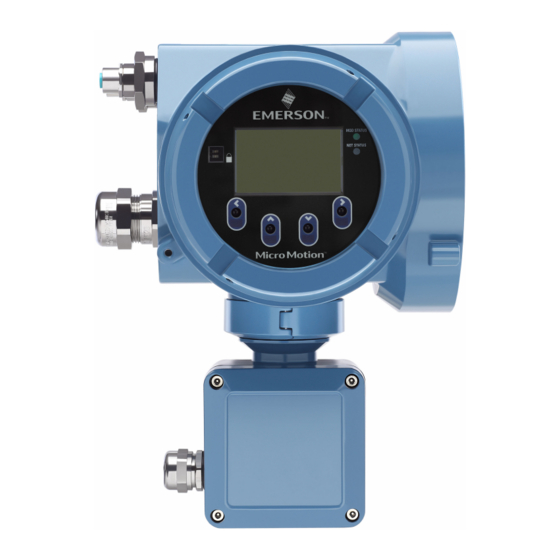
Installation Manual Using the display controls MMI-20075112 August 2020 9 Using the display controls The transmitter display interface includes a display (LCD panel) and four optical switches – left, up, down, and right arrow keys – used to access the display menus and navigate the display screens. Procedure 1. - Page 44 Using the display controls Installation Manual August 2020 MMI-20075112 Figure 9-2: Example 1: Active arrow indicators on the transmitter display Figure 9-3: Example 2: Active arrow indicators on the transmitter display Micro Motion 5700 transmitters for PROFIBUS PA...
-
Page 45: Available Service Port Connection
Installation Manual Available service port connection MMI-20075112 August 2020 10 Available service port connection Use the service port connection to download or upload data from/to the transmitter. To access the service port, use: • Any commonly-available USB drive Note The USB drive must be in FAT format. The transmitter does not recognize NTFS format. •... - Page 46 © 2020 Micro Motion, Inc. All rights reserved. The Emerson logo is a trademark and service mark of Emerson Electric Co. Micro Motion, ELITE, ProLink, MVD and MVD Direct Connect marks are marks of one of the Emerson Automation Solutions family of companies. All other marks are property of their respective owners.
Need help?
Do you have a question about the Micro Motion 5700 and is the answer not in the manual?
Questions and answers