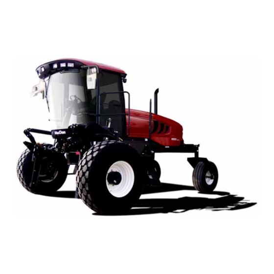
MacDon M155 Unloading And Assembly Instructions
Self-propelled windrower
Hide thumbs
Also See for M155:
- Operator's manual (510 pages) ,
- Unloading and assembly instructions (276 pages) ,
- Installation instructions manual (70 pages)

Related Manuals for MacDon M155


Summary of Contents for MacDon M155
- Page 1 M155 Self-Propelled Windrower Unloading and Assembly Instructions (Container Shipments) 262320 Revision A Original Instruction The Harvesting Specialists.
- Page 2 © 2023 MacDon Industries, Ltd. The information in this publication is based on the information available and in effect at the time of printing. MacDon Industries, Ltd. makes no representation or warranty of any kind, whether expressed or implied, with respect to the...
- Page 3 Benedikt von Riedesel Benedikt von Riedesel Benedikt von Riedesel Benedikt von Riedesel Directeur général, MacDon Europe GmbH Gerente general - MacDon Europe GmbH Peadirektor, MacDon Europe GmbH General Manager, MacDon Europe GmbH Hagenauer Straße 59 Hagenauer Straße 59 Hagenauer Straße 59 Hagenauer Straße 59...
- Page 4 Benedikt von Riedesel Benedikt von Riedesel Benedikt von Riedesel Benedikts fon Rīdīzels Vezérigazgató, MacDon Europe GmbH General Manager, MacDon Europe GmbH Generalinis direktorius, MacDon Europe GmbH Ģenerāldirektors, MacDon Europe GmbH Hagenauer Straße 59 Hagenauer Straße 59 Hagenauer Straße 59 Hagenauer Straße 59...
- Page 5 [4] Not Applicable MacDon Industries Ltd. 680 Moray Street, [5] May 4, 2023 Winnipeg, Manitoba, Canada R3J 3S3 [6] _____________________________ Adrienne Tankeu [3] Part 306489 Product Integrity We, [1] Declare, that the product: Machine Type: [2] Name & Model: [3]...
- Page 6 Introduction This instruction manual describes the unloading, setup, and predelivery requirements for the MacDon M155 Self-Propelled Windrowers shipped in containers. Carefully read all the material provided before attempting to unload, assemble, or use the machine. Retain this instruction for future reference.
-
Page 7: Summary Of Changes
Summary of Changes The following list provides an account of major changes from the previous version of this document. Section Summary of Change Internal Use Only Declaration of Conformity – Windrower Lift Updated the Declaration of Conformity. Technical Sling (B9063), page i Publications 2.3 Removing Wheel and Step Assembly, The following illustrations and associated steps... - Page 8 Section Summary of Change Internal Use Only 6 Attaching Headers, page 123 Reordered attaching topics alphabetically. Technical Publications 6.1.1 Attaching A Series Auger Header – Technical Revised DANGER to mention safety props. Hydraulic Center-Link with Self-Alignment, Publications page 123 6.1.2 Attaching A Series Auger Header – Revised DANGER to mention safety props.
- Page 9 Section Summary of Change Internal Use Only 6.3 Attaching D2 SP Series Draper Header, Added topic. Technical page 161 Publications 6.3.1 Attaching Draper Header Supports, Added topic. Technical page 161 Publications 6.3.2 Attaching D2 SP Series Draper Header – Added topic. Technical Hydraulic Center-Link with Self-Alignment, Publications...
-
Page 11: Table Of Contents
TABLE OF CONTENTS Declaration of Conformity – Windrower Lift Sling (B9063) ...................i Introduction .............................. iv Summary of Changes............................ v Chapter 1: Safety ............................1 1.1 Safety Alert Symbols ..........................1 1.2 Signal Words ............................2 1.3 General Safety ............................3 1.4 Hydraulic Safety .............................5 1.5 Tire Safety.............................6 1.6 Battery Safety ............................7 1.7 Welding Precautions ..........................8... - Page 12 TABLE OF CONTENTS 3.12 Installing Beacons ..........................69 3.13 Installing Slow Moving Vehicle Sign......................71 3.14 Connecting Batteries ........................... 72 3.15 Lubrication ............................73 3.15.1 Lubrication Procedure ......................... 73 3.15.2 Lubrication Points ........................74 3.16 Installing AM/FM Radio ........................75 3.17 Removing Windrower from Assembly Stands ...................
- Page 13 TABLE OF CONTENTS Chapter 6: Attaching Headers ........................ 123 6.1 Attaching A Series Auger Header ......................123 6.1.1 Attaching A Series Auger Header – Hydraulic Center-Link with Self-Alignment ........123 6.1.2 Attaching A Series Auger Header – Hydraulic Center-Link without Self-Alignment........129 6.1.3 Attaching A Series Auger Header –...
- Page 14 TABLE OF CONTENTS 7.3.15 Setting Tire Size ........................226 7.3.16 Setting Engine Intermediate Speed Control ................... 227 7.3.17 Clearing Sub-Acres........................228 7.4 Activating Cab Display Lockouts ......................229 7.4.1 Activating Header Tilt Control Lockout ................... 229 7.4.2 Activating Header Float Control Lockout ..................230 7.4.3 Activating Reel Fore-Aft Control Lockout ..................
- Page 15 TABLE OF CONTENTS 8.1.7 O-Ring Face Seal Hydraulic Fittings....................280 8.1.8 Tapered Pipe Thread Fittings......................282 8.2 Conversion Chart..........................283 8.3 Definitions ............................284 8.4 Lubricants, Fluids, and System Capacities....................286 8.5 Fuel Specifications ..........................288 Predelivery Checklist ..........................289 xiii 262320 Revision A...
-
Page 17: Chapter 1: Safety
Chapter 1: Safety Understanding and consistently following these safety procedures will help to ensure the safety of those operating the machine and of bystanders. 1.1 Safety Alert Symbols The safety alert symbol indicates important safety messages in this manual and on safety signs on the machine. This symbol means: •... -
Page 18: Signal Words
SAFETY 1.2 Signal Words Three signal words, DANGER, WARNING, and CAUTION, are used to alert you to hazardous situations. Two signal words, IMPORTANT and NOTE, identify non-safety related information. Signal words are selected using the following guidelines: DANGER Indicates an imminently hazardous situation that, if it is not prevented, will result in death or serious injury. WARNING Indicates a potentially hazardous situation that, if it is not prevented, could result in death or serious injury. -
Page 19: General Safety
SAFETY 1.3 General Safety Operating, servicing, and assembling machinery presents several safety risks. These risks can be reduced or eliminated by following the relevant safety procedures and wearing the appropriate personal protective equipment. CAUTION The following general farm safety precautions should be part of your operating procedure for all types of machinery. - Page 20 SAFETY • Wear close-fitting clothing and cover long hair. NEVER wear dangling items such as hoodies, scarves, or bracelets. • Keep all shields in place. NEVER alter or remove safety equipment. Ensure that the driveline guards can rotate independently of their shaft, and that they can telescope freely.
-
Page 21: Hydraulic Safety
SAFETY 1.4 Hydraulic Safety Because hydraulic fluid is under extreme pressure, hydraulic fluid leaks can be very dangerous. Follow the proper safety procedures when inspecting hydraulic fluid leaks and servicing hydraulic equipment. • Always place all hydraulic controls in NEUTRAL before leaving the operator’s seat. -
Page 22: Tire Safety
SAFETY 1.5 Tire Safety Understand the risks of handling tires before performing maintenance tasks. WARNING • A tire can explode during inflation, causing serious injury or death. • Follow the proper procedures when mounting a tire. Failure to do so can produce an explosion, causing serious injury or death. -
Page 23: Battery Safety
SAFETY 1.6 Battery Safety Working with lead-acid vehicle batteries presents several safety risks. WARNING • Keep all sparks and flames away from batteries. The electrolyte fluid in the battery cells emits an explosive gas which can build up over time. •... -
Page 24: Welding Precautions
SAFETY 1.7 Welding Precautions The high current and voltage spikes associated with welding can cause damage to the electronic components on the windrower. Before attempting to weld any part of the windrower or an attached header, disconnect all of the electronic module harness connections as well as the battery cables. -
Page 25: Engine Safety
SAFETY 1.8 Engine Safety Operating, maintaining, and servicing an engine presents several safety risks. These risks can be reduced or eliminated by following the relevant safety recommendations. WARNING Do NOT use aerosol starting aids such as ether when attempting to start the engine. Use of these substances could result in an explosion. -
Page 26: Engine Electronics
SAFETY 1.8.2 Engine Electronics The engine control module (ECM) is a sensitive piece of equipment, which can be damaged if the proper safety procedures are not followed. The ECM also regulates various aspects of engine performance, which can affect the safe use of the machine. -
Page 27: Safety Signs
SAFETY 1.9 Safety Signs Safety signs are decals placed on the machine where there is a risk of personal injury, or where the Operator should take extra precautions before operating the controls. They are usually yellow. • Keep safety signs clean and legible at all times. •... -
Page 29: Chapter 2: Unloading Windrower
Chapter 2: Unloading Windrower Unload all windrower parts before beginning assembly. Follow these procedures in the order in which they are presented. 2.1 Unloading Container Unload the windrower properly to avoid damaging the windrower. DANGER Do NOT allow bystanders in the unloading area. 1. -
Page 30: Moving Windrower To Assembly Area
UNLOADING WINDROWER 2.2 Moving Windrower to Assembly Area The windrower can be moved to the assembly area using either a crane or a forklift. • To move the windrower using a crane, refer to 2.2.1 Moving Windrower to Assembly Area – Crane Method, page •... - Page 31 UNLOADING WINDROWER To move the windrower to the assembly area, follow these steps: 1. Attach the chains or cables to the four lifting points on the lift sling, and connect the loop ends to the crane hook. IMPORTANT: Use cables or chains with a minimum lifting capacity of 3221 kg (7100 lb.).
-
Page 32: Moving Windrower To Assembly Area - Forklift Method
UNLOADING WINDROWER 4. Lower windrower onto 152 mm (6 in.) blocks (A) as shown. 5. Remove the chains from the shipping frame. 6. Check for shipping damage and missing parts. 7. Proceed to 2.3 Removing Wheel and Step Assembly, page Figure 2.5: Windrower Shipping Assembly on Blocks 2.2.2 Moving Windrower to Assembly Area –... - Page 33 UNLOADING WINDROWER 1. Approach the windrower from the hood end and slide the forks underneath the lifting framework. 2. Raise the windrower off the platform and move it to the assembly area. Figure 2.6: Forklift Method Lifting Points 3. Lower the windrower onto 152 mm (6 in.) blocks (A) as shown.
-
Page 34: Removing Wheel And Step Assembly
UNLOADING WINDROWER 2.3 Removing Wheel and Step Assembly Remove the wheel and step assembly from their shipping position. 1. Remove shipping wire (A) and the bolt securing the hose support to the shipping frame. Remove the hose support. 2. Lay the hose support off to the side. Figure 2.8: Shipping Frame 3. - Page 35 UNLOADING WINDROWER 4. Remove and discard the following parts from the center-link: • Lynch pin (A) • Both washers (B) • Clevis pin (C) Figure 2.10: Center-Link 5. Remove and discard two carriage head bolts and nuts (A) from both sides of the rear of the wheel/step assembly. Figure 2.11: Rear of Wheel/Step Assembly 262320 Revision A...
- Page 36 UNLOADING WINDROWER 6. Remove cable tie (A) and shipping wire (B) securing the hose bundles to the frame. Figure 2.12: Hose Bundles on Frame Figure 2.13: Hose Bundles on Frame 262320 Revision A...
- Page 37 UNLOADING WINDROWER 7. Using a chain and a lifting device, pull wheel/step assembly (A) away from the shipping assembly. Figure 2.14: Wheel/Step Shipping Assembly 8. Lift center-link (A) until it clears wheel/step assembly frame (B). Figure 2.15: Wheel/Step Assembly Frame 9.
-
Page 38: Removing Drive Wheels
UNLOADING WINDROWER 2.4 Removing Drive Wheels Remove the drive wheels from their shipping position. IMPORTANT: To prevent damage to the hood/cab, remove the drive wheels as a pair from above the hood. 1. Remove and discard two bolts and nuts (A) from the front cross member over the hood. - Page 39 UNLOADING WINDROWER 3. Attach a lifting device to lift hooks (A) located in the center of each drive wheel. Figure 2.19: Drive Wheel 4. Carefully lift the wheels off the frame. IMPORTANT: Ensure the tires are guided away from the cab roof when lifting the wheels to prevent damaging the cab.
-
Page 40: Removing Platforms
UNLOADING WINDROWER 2.5 Removing Platforms Remove the left and right platforms from their shipping position. 1. Lay cardboard onto the ground where the platforms will be lowered onto. NOTE: The cardboard will protect the paint on the platform assembly. 2. Remove support tube (A) on each side of the hood. Figure 2.21: Shipping Supports 3. - Page 41 UNLOADING WINDROWER 5. Remove two 5/8 x 5 in. bolts (B) from the top of the vertical supports, and remove two 5/8 x 1 1/4 in. bolts (A) attaching the angle braces to the platforms. 6. Carefully lift the platform assembly off the frame. Figure 2.23: Platforms on Hood 7.
-
Page 42: Removing Hand Rails And Exhaust Stack
UNLOADING WINDROWER 2.6 Removing Hand Rails and Exhaust Stack Remove the hand rails and exhaust stack from their shipping position. 1. Cut the cable ties and move the hose bundle clear of the platform. Figure 2.26: Hand Rails and Exhaust Stack Shipping Assembly 262320 Revision A... - Page 43 UNLOADING WINDROWER 2. Remove the shipping wire and foam from exhaust stack (A). 3. Remove nuts (B) from clamp (C), and remove exhaust stack (A) and the clamp from the shipping frame. Figure 2.27: Hand Rails and Exhaust Stack Shipping Position 4.
- Page 44 UNLOADING WINDROWER 5. Remove two bolts and nuts (A) securing hand rail (B) to the shipping frame, and remove the hand rail. Retain the two bolts but discard the nuts. 6. Repeat Step 5, page 28 for the hand rail on the opposite side.
-
Page 45: Removing Leg Assemblies
UNLOADING WINDROWER 2.7 Removing Leg Assemblies Remove the left and right leg assemblies from their shipping position. DANGER Objects are heavy and difficult to maneuver. Use a proper lifting device and arrange for adequate assistance. Falling objects can result in serious personal injury. 1. - Page 46 UNLOADING WINDROWER 4. Remove and discard two bolts (A) from the shipping channel located at the top of the leg. Figure 2.33: Shipping Channel on Leg 5. Remove bars (A) from the leg. Discard the bars. 6. Insert cardboard or foam between the leg assembly and the hood to avoid damage.
- Page 47 UNLOADING WINDROWER 7. Lift leg assembly (A), and set it on level ground in position (B) as shown. 8. Repeat Step 1, page 29 to Step 7, page 31 for the second leg assembly. Figure 2.35: Leg Assembly Positioning 262320 Revision A...
-
Page 48: Removing Wheel And Platform Support
UNLOADING WINDROWER 2.8 Removing Wheel and Platform Support The wheel and platform support were installed for shipping purposes only. 1. Remove cross brace (A) and upright supports (B) and (C) from the frame. Discard the cross brace, upright supports, and the hardware that was used to install them. Figure 2.36: Wheel and Platform Support 2. - Page 49 UNLOADING WINDROWER 3. Remove and uprights (A) on both sides of the hood. Discard the uprights and the hardware that was used to install them. Figure 2.38: Wheel and Platform Support 262320 Revision A...
-
Page 51: Chapter 3: Assembling Windrower
Chapter 3: Assembling Windrower Once the windrower has been unloaded, assembly can begin. 3.1 Lifting Windrower onto Assembly Stand (B9064) The windrower must be assembled on a MacDon Export Assembly Lift Stand (B9064). DANGER Do NOT allow bystanders in the unloading area. - Page 52 ASSEMBLING WINDROWER Figure 3.1: Assembly Stand Setup 2. Set the assembly stands on level ground to maintain the difference in height between the assembly stands: • Rear assembly stand height (A) is 1240 mm (48 13/16 in.). • Front assembly stand height (B) is 1291 mm (50 13/16 in.) 3.
- Page 53 ASSEMBLING WINDROWER Figure 3.2: Windrower on Assembly Stands 6. Lift the windrower onto the assembly stand. Position the windrower so that you can remove fork channels (B) with a forklift, and without contacting front tractor stand (A). 262320 Revision A...
-
Page 54: Installing Legs
ASSEMBLING WINDROWER 3.2 Installing Legs The right and left wheel legs are large components that must be installed before assembling the windrower any further. 1. Remove and retain the following: • Front leg bolt (A) • Two washers (B) • Pin (C) •... - Page 55 ASSEMBLING WINDROWER 4. Position leg (A) close to frame channel (B). Figure 3.5: Leg Position 5. Feed hydraulic hose bundle (A) from the leg into the frame and through hole (B) at the center of the frame. Figure 3.6: Hydraulic Hoses 262320 Revision A...
- Page 56 ASSEMBLING WINDROWER 6. Insert the leg into the frame and line up the holes in the frame and the leg at the first position (widest tread with one exposed hole [A]). 7. Insert pins (B) and secure the with the following hardware F F E (retained from Step 1, page...
-
Page 57: Installing Drive Wheels
ASSEMBLING WINDROWER 3.3 Installing Drive Wheels Be sure to check the wheel nut torque again once the windrower has begun operation. 1. Remove shipping support (A) from the drive wheel hub, and remove the wheel lug nuts (B). Discard shipping support (A). - Page 58 ASSEMBLING WINDROWER 6. Install and hand-tighten wheel nuts (A). IMPORTANT: To prevent damage to the wheel rim, tighten the nuts by hand. Do NOT use an impact wrench to tighten the wheel nuts. Do NOT apply lubricant or anti-seize compound to the threads of the wheel studs.
-
Page 59: Installing Caster Wheels
ASSEMBLING WINDROWER 3.4 Installing Caster Wheels Install the two caster wheels onto the walking beam near the engine. 1. Remove two guide plates (A) from the ends of the walking beam. Discard the guide plates and the hardware that was used to install them. Figure 3.12: Guide Plate on Walking Beam 2. - Page 60 ASSEMBLING WINDROWER 3. Remove tie bar (A) from between the caster wheels. Discard tie bar (A) and the hardware that was used to install it. Figure 3.14: Caster Wheel Shipping Assembly 4. Remove and discard the bolts and nuts from locations (A). 5.
- Page 61 ASSEMBLING WINDROWER 7. Attach a chain to the right caster and support the caster with a lifting device that has a minimum lifting capacity of 2268 kg (5000 lb.). Make sure both bearing lock collars (A) are locked before lifting the caster. Figure 3.16: Lifting Device on Caster 8.
- Page 62 ASSEMBLING WINDROWER CAUTION Stand clear when lifting, as caster may swing. 9. Lift the caster assembly off of the shipping frame and position it at the end of walking beam (A). 10. Insert the right caster extension into the walking beam and position it for the desired tread.
- Page 63 ASSEMBLING WINDROWER Figure 3.19: Walking Beam Installation 11. Install four 3/4 x 2 1/4 in. bolts (A) and washers into the walking beam. 12. Connect anti-shimmy dampener (E) to anti-shimmy bracket (B) using the bolt and nut (D) what was shipped attached to the dampener.
- Page 64 ASSEMBLING WINDROWER Figure 3.20: Walking Beam Installation 14. Snug up two bolts (A) underneath the beam. 15. Tighten four back bolts (B) to 447 Nm (330 lbf·ft). 16. Tighten bolts (A) underneath beam to 447 Nm (330 lbf·ft). 17. Tighten nut (C) to 136 Nm (100 lbf·ft). Make sure anti-shimmer dampener (D) is parallel to the walking beam while you tighten nut (D).
- Page 65 ASSEMBLING WINDROWER 20. Remove and retain four 1/2 x 1 in. bolts (A) and two step assemblies (B) from the shipping frame. These parts will be used in 3.9 Installing Steps, page 65. Discard the remaining shipping frame components and hardware. B A A Figure 3.21: Shipping Frame and Steps 262320...
-
Page 66: Installing Hydraulics
ASSEMBLING WINDROWER 3.5 Installing Hydraulics Reconnect the hydraulic hoses that were disconnected for shipping purposes. 1. Retrieve all capped hoses from inside the frame. 2. Locate the three hoses with capped tees extending from the valve block. 3. Remove the caps from the fittings with similar colored cable ties, and connect hoses (A) to tees. - Page 67 ASSEMBLING WINDROWER 12. Position four hoses (A), (B), (C), and (D) against the support as shown and secure the hoses with plastic ties. Figure 3.24: Hydraulic Hose Routing A - Hose (MD #111323) Connected To Valve Block Port B — Orange Tie B - Hose (MD #111323) Connected To Valve Block Port A —...
- Page 68 ASSEMBLING WINDROWER 14. Insert two left traction drive hoses (A) into the hose block as shown. Case drain hose (B) is preinstalled in the block. 15. Insert two right traction drive hoses (C) into the hose block as shown. Figure 3.26: Hose Block – View Looking Forward 16.
- Page 69 ASSEMBLING WINDROWER NOTE: The front two traction drive pump ports are for the wheel motor on the LEFT side of the windrower. 18. Attach hose (A) (no tie) to pump port D (no tie). Tighten the fittings. 19. Attach hose (B) (yellow tie) to pump port C (C) (yellow tie). Tighten the fittings.
- Page 70 ASSEMBLING WINDROWER 28. Secure the hoses with cable ties (A) as needed. Figure 3.32: Hose Routing 29. Retrieve wheel leg harness connectors C7B (A) and C6B (C) from inside the frame. NOTE: C7B (A) is attached to the harness labeled as MD #109755. C6B (C) is attached to the harness labeled as MD #109545.
- Page 71 ASSEMBLING WINDROWER 32. Remove any straps that secure electrical harness (D) to hydraulic hose bundle (A). 33. Route hose bundle (A) and hose (B) through hose support (C) and lay the hoses on the tire. 34. Route electrical harness (D) along the right side of hose support (C) as shown.
- Page 72 ASSEMBLING WINDROWER 38. Disengage and rotate hook (A) to the fully up position. 39. Position hose bundle (B) over the hose support and under the hook. Figure 3.36: Hook Positioning 40. Route electrical harness (A) along the topside of hose bundle (B) as shown to prevent chafing of the electrical wires when the windrower is operating with a header.
- Page 73 ASSEMBLING WINDROWER 42. Lower hook (A) and engage it in bracket (B) in the down position. 43. Secure the electrical harness to the hose bundle using fabric strap (C). 44. Attach electrical harness coupler (D) to the hose support. Figure 3.38: Hook Positioning and Harness Routing 45.
-
Page 74: Removing Battery Shipping Shield
ASSEMBLING WINDROWER 3.6 Removing Battery Shipping Shield Remove and discard the shield that protects the battery during shipping. 1. Loosen nut (A) on the battery clamp. 2. Slide shield (B) out from under the battery and discard. 3. Tighten nut (A) on the battery clamp. Figure 3.40: Battery Shipping Shield 4. -
Page 75: Unpacking Ignition Keys
ASSEMBLING WINDROWER 3.7 Unpacking Ignition Keys The ignition keys are shipped attached to the fuse box cover. The fuse box is mounted on the right (cab-forward) side of the frame under the platform. Figure 3.43: Fuse Box Location 1. Remove wing nut (A) from fuse box cover (B) and remove the cover. - Page 76 ASSEMBLING WINDROWER 2. Remove tape and keys (A) from inside the cover. 3. Unlock the cab doors and place the keys on the console. 4. Close the cab doors. 5. Install fuse box cover (B) and secure it with the wing nut. Figure 3.45: Fuse Cover 262320 Revision A...
-
Page 77: Installing Platforms
ASSEMBLING WINDROWER 3.8 Installing Platforms Install the platforms and railings on the both sides of the windrower. NOTE: The procedure for the left side installation is shown. The procedure for the right side is similar. 1. Remove two 1/2 x 3/4 in. bolts (A) securing the rails to the shipping beam, and remove the rails. - Page 78 ASSEMBLING WINDROWER 5. Attach the main beam of the platform to the side frame using three 1/2 x 1 1/4 in. long carriage bolts (A). Ensure the bolt heads face inboard, and tighten them just enough to allow you to reposition the platform while installing it. Figure 3.49: Left Platform –...
- Page 79 ASSEMBLING WINDROWER 9. Slowly close the platform and check that the vertical rail tubes are parallel with the cab posts when viewed from the rear. 1005709 Figure 3.52: Left Platform 10. Laterally adjust king pin mounting (A) as needed. Figure 3.53: Left Platform – Main Beam 11.
- Page 80 ASSEMBLING WINDROWER 12. Ensure the front of the platform is contacting guide (A). Figure 3.55: Left Platform – Guide 13. Adjust the platform horizontally with 1/2 x 2 1/4 in. bolt (A) as needed. Figure 3.56: Left Platform – Main Beam 14.
-
Page 81: Installing Steps
ASSEMBLING WINDROWER 3.9 Installing Steps The windrower steps must be moved from their shipping position and installed. NOTE: The procedure for installing the left steps is shown—installation of the right steps is similar. 1. Remove two existing upper bolts (A). 2. -
Page 82: Installing Exhaust Stack
ASSEMBLING WINDROWER 3.10 Installing Exhaust Stack Set up the exhaust assembly. 1. Open the engine compartment hood. 2. Retrieve exhaust stack (A) and clamp (B) (unpacked in Removing Hand Rails and Exhaust Stack, page 26). 3. Loosen clamp (B) on exhaust stack (A). Figure 3.60: Exhaust Stack 4. - Page 83 ASSEMBLING WINDROWER 6. Tighten both clamps (A) just enough to permit stack (B) to move. Figure 3.63: Exhaust Stack under Hood 7. Close the hood slowly so stack (A) enters hole (B) in the hood. Adjust the position of the stack as required to clear the hole in the hood.
-
Page 84: Positioning Light And Mirror Assemblies
ASSEMBLING WINDROWER 3.11 Positioning Light and Mirror Assemblies The mirror/light support arms must be moved from the shipping position to the working position. 1. Remove nut and bolt (A) securing the light and mirror assembly. 2. Swing light and mirror assembly (B) forwards and upwards. Figure 3.66: Light and Mirror Assembly in Shipping Position 3. -
Page 85: Installing Beacons
ASSEMBLING WINDROWER 3.12 Installing Beacons Install the beacons onto the mounting plates located near the cab-forward mirror arms. 1. Retrieve the two beacons from the shipment. 2. Remove the hardware and rubber base from one of the beacons as shown. Figure 3.68: Beacon Light 3. - Page 86 ASSEMBLING WINDROWER 7. Fit the beacon onto the base, making sure the beacon is oriented with the point on the lens facing cab-forward as shown. Figure 3.71: Beacon Light Orientation 8. Mount the beacon to the base using lock washers and nuts (A) supplied with the beacon.
-
Page 87: Installing Slow Moving Vehicle Sign
ASSEMBLING WINDROWER 3.13 Installing Slow Moving Vehicle Sign The slow moving vehicle (SMV) sign is placed inside the cab for shipping. It must be installed on the windrower in a location where it will be visible during road travel. 1. Retrieve SMV sign (A) from inside the cab. 2. -
Page 88: Connecting Batteries
ASSEMBLING WINDROWER 3.14 Connecting Batteries Connecting the batteries provides electrical power to the windrower. 1. Open the right maintenance platform. 2. Ensure battery main disconnect switch (A) is turned to the POWER OFF position. NOTE: The battery main disconnect switch is located on the right frame rail beside the batteries. -
Page 89: Lubrication
ASSEMBLING WINDROWER 3.15 Lubrication Proper lubrication is essential to ensuring the service life of the windrower. For information on the type of lubricants to use, refer to 8.4 Lubricants, Fluids, and System Capacities, page 286. 3.15.1 Lubrication Procedure This procedure should be followed when you are adding grease to each fitting. 1. -
Page 90: Lubrication Points
ASSEMBLING WINDROWER 3.15.2 Lubrication Points Add grease to these fittings before delivering the windrower. Be sure to leave a small blob of grease on top of each fitting to prevent contamination. Figure 3.78: Lubrication Points A - Forked Caster Wheel Bearing (Two Places) (Outer – Both Wheels) B - Top-Link (Two Places) (Both Sides) C - Lubrication Decal (MD #183411) D - Caster Pivot (Both Sides) -
Page 91: Installing Am/Fm Radio
ASSEMBLING WINDROWER 3.16 Installing AM/FM Radio The windrower is designed to accommodate an AM/FM radio of a specific size and type. Windrowers are designed to accept a DIN E style AM/FM radio with depth (X) of 161 mm, and with a 5 mm threaded centered on the rear of the radio for support in location (A). - Page 92 ASSEMBLING WINDROWER 2. Remove the radio panel by removing four screws (A). Figure 3.81: Radio Panel 3. Remove screw (A) and nut (C) to remove support (B) from the panel. Retain nut (C) and the lock washer. 1005779 Figure 3.82: Panel Support 4.
- Page 93 ASSEMBLING WINDROWER 5. Position receptacle (A) (supplied with the radio) into the opening, and secure it by bending tabs (B) on the receptacle against the panel. 1005780 Figure 3.84: Radio Receptacle 6. Insert the radio into the receptacle and attach the radio bezel.
- Page 94 ASSEMBLING WINDROWER 10. Attach the stud (supplied with the radio) to the center rear of the radio. 11. Attach support (B) to the stud on the back of the radio with nut (A) and the lock washer supplied with the support. NOTE: The support can be attached to the radio in multiple locations to allow for proper radio mounting.
- Page 95 ASSEMBLING WINDROWER 16. Turn battery switch (A) to the ON position. 17. Turn the ignition key to ACC, switch the radio ON, and check the operation in accordance with the instructions supplied with the radio. 18. Turn the ignition key to the OFF position, and remove the key.
-
Page 96: Removing Windrower From Assembly Stands
ASSEMBLING WINDROWER 3.17 Removing Windrower from Assembly Stands Once the windrower is assembled, remove it from the assembly stands so that pre-delivery and operational checks can be performed. 1. Position a jack under the jack point of each drive wheel leg and under the rear hitch. 2. -
Page 97: Chapter 4: Predelivery Checks
Chapter 4: Predelivery Checks The predelivery checklist included with this manual and several operational checks will need to be completed before the windrower can be delivered to the customer. 1. Perform the predelivery checks listed in the Predelivery Checklist, page 289. - Page 98 PREDELIVERY CHECKS Engine serial number plate (A) is located on top of the engine cylinder head cover as shown. Figure 4.3: Engine Serial Number Location 262320 Revision A...
-
Page 99: Checking Tire Pressures And Adding Tire Ballast
PREDELIVERY CHECKS 4.2 Checking Tire Pressures and Adding Tire Ballast Checking the tire pressure and possibly adding tire ballast will help ensure the proper operation of the windrower. 4.2.1 Checking Tire Pressure The windrower’s drive and caster tires must be inflated to the proper pressure level. To inspect a tire’s air pressure level: 1. - Page 100 PREDELIVERY CHECKS Table 4.2 Recommended Ballast Weight (continued) 7.5 x 16 7.6 m (25 ft.) and smaller 10 x 16 16.5 x 16.1 9.1 m (30 ft.) single or double 7.5 x 16 reel without conditioner 38 (10) 91 (200) 10 x 16 10.7 m (35-ft.) single reel 16.5 x 16.1...
-
Page 101: Checking Engine Air Intake
1. Ensure air cleaner cap is firmly attached and latches (A) and clamps (B) are secure. Figure 4.4: M155 Air Intake System 2. Check the constant torque spring clamp (A) at the back of the air cleaner. Hold a 0.46 mm (0.018 in.) gauge between the middle coils, tighten the clamp until the gauge is snug, and remove the gauge. -
Page 102: Checking Hydraulic Oil Level
PREDELIVERY CHECKS 4.4 Checking Hydraulic Oil Level The hydraulic oil reservoir can be found in the engine bay. The hydraulic oil level can be inspected using the sight glass on the side of the reservoir, or by using the dipstick. 1. -
Page 103: Checking Fuel Separator
PREDELIVERY CHECKS 4.5 Checking Fuel Separator The fuel separator removes water and sediment from the fuel to prevent damage to the engine. It will need to be inspected to ensure that it is clean. 1. Place a container under filter drain valve (A). 2. -
Page 104: Checking Engine Oil Level
PREDELIVERY CHECKS 4.6 Checking Engine Oil Level Ensure the engine oil is filled to the correct level. 1. Remove dipstick (A) by turning it counterclockwise to unlock it. 2. Wipe the dipstick clean and reinsert it into the engine. 3. Remove the dipstick again and check the oil level. Figure 4.9: Engine Oil Dipstick 4. -
Page 105: Checking Gearbox Lubricant Level
PREDELIVERY CHECKS 4.7 Checking Gearbox Lubricant Level Ensure the gearbox lubricant is filled to the correct level. 1. Locate gearbox oil level check plug (A) under the machine. Remove plug (A) and ensure lubricant is visible or slightly running out. 2. -
Page 106: Checking Engine Coolant
PREDELIVERY CHECKS 4.8 Checking Engine Coolant Coolant is cycled through the engine to help reduce internal heat. The coolant must be at the appropriate level for the system to work correctly. 1. Visually inspect the coolant level in the coolant recovery tank (A). -
Page 107: Checking Air Conditioning Compressor Belt
PREDELIVERY CHECKS 4.9 Checking Air Conditioning Compressor Belt The windrower’s air conditioner compressor is belt-driven. The belt must be tensioned correctly for the air conditioning system to function properly. 1. Ensure that A/C compressor belt (A) is tensioned so that a force of 45 N (10 lbf) applied to the midspan of the belt deflects it by 5 mm (3/16 in.). -
Page 108: Starting Engine
PREDELIVERY CHECKS 4.10 Starting Engine The procedure for starting the windrower’s engine varies depending on the ambient temperature. In cold weather, the engine must go through a warm-up cycle before the engine speed can be increased. CAUTION Park on a level surface with the ground speed lever (GSL) in the N-DETENT position and the steering wheel in the locked (centered) position. - Page 109 PREDELIVERY CHECKS Normal start: 6. Follow these steps when starting the engine when the ambient temperature is above 16°C (60°F): Move the throttle fully back to START position (A). b. Sound the horn three times. NOTE: The horn is located on the headliner. Turn ignition key (B) to the RUN position.
- Page 110 Faulty fuel injectors • Contact a MacDon Dealer or MacDon Product Support • Check diesel exhaust fluid (DEF) coolant hose routing, ensure the Aftertreatment error on start up coolant pressure lines, marked with red cable ties, are connected together, and not crossed with the return line.
-
Page 111: Priming Hydraulic System
PREDELIVERY CHECKS 4.11 Priming Hydraulic System In order for the windrower’s hydraulic system to perform properly, the hydraulic fluid must be completely free of air. Priming the hydraulic system will purge any trapped air. The hydraulic system may require priming when one of its components (for example, a hydraulic pump) is replaced. - Page 112 PREDELIVERY CHECKS 5. Locate plug (A) on the top of the header drive pump housing. 6. Loosen plug (A) to bleed the pump housing. Retighten the plug once oil starts to run out. Figure 4.21: Header Drive Pump Housing 7. Locate plug (A) on the top of the traction drive pump housing.
- Page 113 PREDELIVERY CHECKS 10. Open the left platform. 11. Disconnect brake engage solenoid plug (P44) (A) from the multifunction block on the left side of the windrower. Figure 4.23: Multifunction Control Manifold Figure 4.24: Fuel Pump Location 12. Disconnect 2-pin electrical connection (A) near fuel pump (B) on the right side of the engine. 262320 Revision A...
- Page 114 PREDELIVERY CHECKS 13. Open the maintenance platform on the right (cab- forward) side. 14. Open fuse cover (A). Figure 4.25: Fuse Cover 15. Remove ignition power fuse (15A) (A). DANGER Ensure that all bystanders have cleared the area. 16. Prime the system by cranking the engine with the ignition key for 15 seconds.
- Page 115 PREDELIVERY CHECKS 20. Check the hydraulic oil level in the reservoir (remove filler cap / dipstick (A) and add SAE 15W-40 oil if necessary). For instructions, refer to 4.4 Checking Hydraulic Oil Level, page 21. Close the platforms. Figure 4.27: Filler Cap 262320 Revision A...
-
Page 116: Checking And Adding Wheel Drive Lubricant
PREDELIVERY CHECKS 4.12 Checking and Adding Wheel Drive Lubricant The lubricant level in the windrower’s wheel drives can be inspected through the lubricant ports. DANGER To prevent bodily injury or death from the unexpected startup of the machine, always stop the engine and remove the key from the ignition before leaving the operator’s seat for any reason. -
Page 117: Checking Traction Drive
PREDELIVERY CHECKS 4.13 Checking Traction Drive The drive wheels should spin either at the same speed or at different speeds depending on how you steer the windrower. DANGER Ensure that all bystanders have cleared the area. 1. Move ground speed lever (GSL) (A) out of N-DETENT and slowly move the GSL forward. -
Page 119: Chapter 5: Performing Operational Checks
Chapter 5: Performing Operational Checks Perform all procedures in this chapter in the order in which they are listed. 5.1 Checking Safety System The operating safety system protects the operator and the windrower from injury or damage. Perform these checks to ensure that the operating safety system is functioning correctly. - Page 120 PERFORMING OPERATIONAL CHECKS Header drive engaged safety check: 2. Shut down the engine, and pull up on collar (B) while pressing down on switch (A) to engage the header drive. 3. Try starting the engine and confirm the cab display module (CDM) displays HEADER ENGAGED on the upper line and DISENGAGE HEADER on the lower line.
- Page 121 PERFORMING OPERATIONAL CHECKS Steering and neutral safety check: 14. Shut down the engine and center the steering wheel. Place the GSL (A) in NEUTRAL, but not in N-DETENT. 15. Try starting the engine and confirm the CDM flashes CENTER STEERING on the upper line and PLACE GSL INTO N on the lower line accompanied by a short beep with each flash.
-
Page 122: Checking Engine Warning Lights
PERFORMING OPERATIONAL CHECKS 5.2 Checking Engine Warning Lights Upon engine startup, a single loud tone sounds, and engine warning lights illuminate as a self-test. 1. Turn ignition key (A) to RUN position. A single loud tone will be audible and the engine warning lights (B) will illuminate. 2. -
Page 123: Checking Windrower Startup
PERFORMING OPERATIONAL CHECKS 5.3 Checking Windrower Startup Ensure that the windrower functions as expected after startup. DANGER Ensure that all bystanders have cleared the area. 1. Start the engine. NOTE: The brakes should engage and the machine should not move after engine start-up. 2. -
Page 124: Checking Engine Speed
5. Check the engine speed on CDM (A) and compare it to the value in the table below. Table 5.1 Engine Speed Maximum rpm (No Load) Model Idle M155 1100 2320–2350 6. Shut down the engine, and remove the key from Figure 5.8: Cab Display Module (CDM) the ignition. -
Page 125: Checking Gauges And Cab Display Module Display
PERFORMING OPERATIONAL CHECKS 5.5 Checking Gauges and Cab Display Module Display All gauges in the cab must function as expected. 1. Ensure engine temperature gauge (A) and fuel gauge (B) are working. Figure 5.9: Temperature and Fuel Gauges 2. Ensure cab display module (CDM) display (A) is working by pushing SELECT button (B) on the CDM or SELECT button (C) on the ground speed lever (GSL). -
Page 126: Checking Electrical System
PERFORMING OPERATIONAL CHECKS 5.6 Checking Electrical System The electrical system can be checked using the cab display module (CDM). 1. Push SELECT button (C) on the ground speed lever (GSL) or SELECT button (B) on the cab display module (CDM) until CDM display (A) shows VOLTS. -
Page 127: Checking Operator Presence System
PERFORMING OPERATIONAL CHECKS 5.7 Checking Operator Presence System The operator presence system is a safety feature that requires someone to sit in the operator's seat in order for the windrower to be operational. DANGER Ensure that all bystanders have cleared the area. NOTE: A header must be installed on the windrower before this operational check can be performed. - Page 128 PERFORMING OPERATIONAL CHECKS 7. Start the engine and drive the windrower at a speed MORE THAN 8 km/h (5 mph): Stand up from the operator’s seat. b. The CDM beeps once and displays NO OPERATOR on the lower line. If the CDM does not beep and display this message, the operator presence system requires adjustment.
-
Page 129: Checking Exterior Lights
PERFORMING OPERATIONAL CHECKS 5.8 Checking Exterior Lights Remove any plastic film (if present) from the exterior lights. Check all parts of the exterior lighting system for functionality. NOTE: Rotate the operator’s seat to cab-forward mode before checking the exterior lights. If the operator’s seat is already in cab- forward mode, skip to Step 5, page 114. - Page 130 PERFORMING OPERATIONAL CHECKS 5. Turn field light switch (A) to the ON position and ensure front field lights (B), rear flood lights (C), and rear swath lights (D) are functioning. Figure 5.14: Exterior Lights – Cab Forward 262320 Revision A...
- Page 131 PERFORMING OPERATIONAL CHECKS 6. Turn road light switch (A) to the ON position and ensure front road lights (B) and rear red tail/brake lights (C) (if equipped) are functioning. 7. Activate high/low switch (D) and check lights. 8. Activate amber turn signal/hazard warning lights (E) using switches on the cab display module (CDM) and check lights.
- Page 132 PERFORMING OPERATIONAL CHECKS 10. Turn beacon switch (A) to the ON position and ensure amber beacons (B) are functioning. 11. If an exterior light is not functioning, refer to the windrower technical manual. Figure 5.16: Exterior Lights – Beacons 262320 Revision A...
-
Page 133: Checking Horn
PERFORMING OPERATIONAL CHECKS 5.9 Checking Horn The horn is a safety device for notifying other people of the windrower’s presence. The functionality of the horn will need to be verified. Push HORN button (A) and listen for the horn. Figure 5.17: Horn Button 262320 Revision A... -
Page 134: Checking Interior Lights
PERFORMING OPERATIONAL CHECKS 5.10 Checking Interior Lights Interior lights provide visibility within the cab. Check all parts of the interior lighting system for functionality. 1. Switch road and field lights ON and OFF using switch (A). NOTE: Ambient light in roof liner (B) and interior light (C) work only when road or field lights (A) are switched ON. -
Page 135: Checking Air Conditioning And Heater
PERFORMING OPERATIONAL CHECKS 5.11 Checking Air Conditioning and Heater The windrower’s cab is equipped with a heating, ventilation, and air conditioning system. Ensure that this system and its controls are functioning properly. Figure 5.19: Air Conditioning (A/C) and Heater Controls 1. -
Page 136: Checking Manuals
PERFORMING OPERATIONAL CHECKS 5.12 Checking Manuals MacDon includes manuals with every windrower to provide information on the windrower’s safe operation and maintenance. The presence of the manuals in the windrower’s manual storage case will need to be verified. Manuals are stored in the manual storage case (A) behind the operator’s seat. -
Page 137: Performing Final Steps
PERFORMING OPERATIONAL CHECKS 5.13 Performing Final Steps Once the Predelivery Checklist and the operational checks have been completed, the windrower cab will need to be prepared for its Operator, and any remaining kits will need to be installed. 1. After the predelivery checks are complete, remove the plastic covering from the cab display module (CDM) and the seats. -
Page 139: Chapter 6: Attaching Headers
6.1.3 Attaching A Series Auger Header – Mechanical Center- Link, page 135 Figure 6.1: M155 and A40D Auger Header 6.1.1 Attaching A Series Auger Header – Hydraulic Center-Link with Self-Alignment The header will need to be physically attached to the windrower, and the hydraulic and electrical connections completed. - Page 140 ATTACHING HEADERS 3. Check that the float engagement pin is installed in storage position (B) and NOT in engaged position (A). IMPORTANT: To prevent damage to the lift system when lowering the header lift linkages without a header or a weight box attached to the windrower, ensure that the float engagement pin is installed in storage position (B) and NOT in engaged position (A).
- Page 141 ATTACHING HEADERS 6. Drive the windrower slowly forward until windrower feet (A) enter header supports (B). Continue driving slowly forward until the feet engage the supports and the header is nudged forward. Figure 6.6: Header Support 7. Use the following GSL functions to position the center-link hook above the header attachment pin: •...
- Page 142 ATTACHING HEADERS 11. Press HEADER UP switch (A) to raise the header to its maximum height. 12. If one end of the header does NOT fully rise, rephase the lift cylinders as follows: Press and hold the HEADER UP switch until both cylinders stop moving.
- Page 143 ATTACHING HEADERS 14. Install clevis pin (A) through the support and the foot and secure it with the hairpin. IMPORTANT: Ensure clevis pin (A) is fully inserted and the hairpin is installed behind the bracket. 15. Repeat the previous step to secure the support on the other side of the header.
- Page 144 ATTACHING HEADERS 20. Disengage the safety prop by turning lever (A) downwards until the lever locks into the vertical position. 21. Repeat the previous step to disengage the other safety prop. Figure 6.14: Safety Prop Lever 22. Start the engine, and press HEADER DOWN switch (A) on the GSL to fully lower the header.
-
Page 145: Attaching A Series Auger Header - Hydraulic Center-Link Without Self-Alignment
ATTACHING HEADERS 6.1.2 Attaching A Series Auger Header – Hydraulic Center-Link without Self- Alignment The header will need to be physically attached to the windrower, and the hydraulic and electrical connections completed. If the windrower is equipped with a hydraulic center-link that lacks the self-alignment capability, the Operator will have to manually attach the hydraulic center-link’s hook to the header’s center pin. - Page 146 ATTACHING HEADERS DANGER Ensure that all bystanders have cleared the area. 4. Start the engine and activate HEADER DOWN button (A) on the ground speed lever (GSL) to fully retract the header lift cylinders. Figure 6.19: Ground Speed Lever 5. Remove pin (A) from the frame linkage and raise center- link (B) until the hook is above the attachment pin on the header.
- Page 147 ATTACHING HEADERS 7. Use the following ground speed lever functions to position the center-link hook above the header attachment pin: • HEADER TILT UP (A) to retract the center-link • HEADER TILT DOWN (B) to extend the center-link 8. Shut down the engine, and remove the key from the ignition.
- Page 148 ATTACHING HEADERS 14. Engage the safety props on both lift cylinders: Shut down the engine, and remove the key from the ignition. b. Pull lever (A) and rotate it towards the header to release and lower safety prop (B) onto the lift cylinder. Repeat the previous steps for the opposite lift cylinder.
- Page 149 ATTACHING HEADERS 16. Remove the lynch pin from clevis pin (A) in stand (B). 17. Hold stand (B) and remove pin (A). 18. Move stand (B) to the storage position by inverting it and relocating it onto the bracket as shown. Reinsert clevis pin (A) and secure it with the lynch pin.
- Page 150 ATTACHING HEADERS 22. Start the engine, and press HEADER DOWN switch (A) on the GSL to fully lower the header. 23. Shut down the engine, and remove the key from the ignition. Figure 6.30: Ground Speed Lever 24. Connect header drive hoses (A) and electrical harness (B) to the header.
-
Page 151: Attaching A Series Auger Header - Mechanical Center-Link
ATTACHING HEADERS 6.1.3 Attaching A Series Auger Header – Mechanical Center-Link The header will need to be physically attached to the windrower, and the hydraulic and electrical connections completed. On windrowers with a mechanical center-link, the center-link will need to be manually connected to the header’s center pin. - Page 152 ATTACHING HEADERS DANGER Ensure that all bystanders have cleared the area. 4. Start the engine and activate HEADER DOWN button (A) on the ground speed lever (GSL) to fully retract the header lift cylinders. Figure 6.34: Ground Speed Lever 5. Drive the windrower slowly forward until boots (A) enter header legs (B).
- Page 153 ATTACHING HEADERS 11. Start the engine. 12. Press HEADER UP switch (A) to raise the header to its maximum height. 13. If one end of the header does NOT fully raise, rephase the lift cylinders as follows: Press and hold the HEADER UP switch until both cylinders stop moving.
- Page 154 ATTACHING HEADERS 15. Install clevis pin (A) through the support and the foot and secure it with the hairpin. IMPORTANT: Ensure clevis pin (A) is fully inserted and the hairpin is installed behind the bracket. Figure 6.39: Header Support 16. Remove the lynch pin from clevis pin (A) in stand (B). 17.
- Page 155 ATTACHING HEADERS 20. Disengage the safety prop by turning lever (A) downwards until the lever locks into the vertical position. 21. Repeat the previous step to disengage the other safety prop. Figure 6.42: Safety Prop Lever 22. Start the engine, and press HEADER DOWN switch (A) on the GSL to fully lower the header.
- Page 156 ATTACHING HEADERS 25. Connect reel hydraulics (A) to the corresponding connections at the right cab-forward side of the windrower. For instructions, refer to the header operator’s manual. Figure 6.45: Reel Hydraulics 262320 Revision A...
-
Page 157: Attaching D Or D1 Sp Series Draper Header
6.2.4 Attaching D or D1 SP Series Draper Header – Mechanical Center-Link, page 155 Figure 6.46: M155 Draper Header Hydraulics 6.2.1 Attaching Draper Header Supports Header supports are required to attach a D Series or D1 SP Series Draper Header to the windrower. Attach header supports to the windrower’s lift linkage if they are not already installed. -
Page 158: Attaching D Or D1 Sp Series Draper Header - Hydraulic Center-Link With Self-Alignment
ATTACHING HEADERS 1. Shut down the engine, and remove the key from the ignition. 2. Remove pin (B) from support (A). Figure 6.48: Header Support 3. Position support (B) onto lift linkage (A) and reinstall pin (C). The pin may be installed from either side of the support. - Page 159 ATTACHING HEADERS 2. If the windrower was previously attached to an R Series Rotary Disc Header, make sure to remove the forming shield (not shown), including forming shield support brackets (A) and hardware (B) from both legs. You can store the brackets and hardware in the windrower tool box.
- Page 160 ATTACHING HEADERS 5. Ensure that the float engagement pin is installed in storage position (B) and NOT in engaged position (A). IMPORTANT: Removing the float will release the tension in the float springs. This will prevent damage to the header lift linkages when lowering the legs without a header or weight box attached to the windrower.
- Page 161 ATTACHING HEADERS 8. Drive the windrower slowly forward until boots (A) enter header legs (B). Continue driving slowly forward until the lift linkages contact the support plates in the header legs and the header is nudged forward. 9. Ensure that the lift linkages are properly engaged in the header legs and are contacting the support plates.
- Page 162 ATTACHING HEADERS 13. Press HEADER UP switch (A) to raise the header to its maximum height. 14. If one end of the header does NOT fully rise, rephase the lift cylinders as follows: Press and hold the HEADER UP switch until both cylinders stop moving.
- Page 163 ATTACHING HEADERS 16. Install pin (B) through the header leg, engaging the U-bracket in the lift linkage. Secure the pin with hairpin (A). 17. Repeat the previous step on the other side of the header. 18. Raise header stand (D) to its storage position by pulling spring pin (C) and lifting the stand into the uppermost position.
- Page 164 ATTACHING HEADERS 22. Start the engine, and press HEADER DOWN switch (A) on the GSL to fully lower the header. 23. Stop the engine, and remove the key from the ignition. Figure 6.64: Ground Speed Lever 24. Connect header drive hoses (A) and electrical harness (B) to the header.
-
Page 165: Attaching D Or D1 Sp Series Draper Header - Hydraulic Center-Link Without Self-Alignment
ATTACHING HEADERS 6.2.3 Attaching D or D1 SP Series Draper Header – Hydraulic Center-Link without Self-Alignment The header will need to be physically attached to the windrower, and the hydraulic connections completed. If the windrower is equipped with a hydraulic center-link that lacks the self-alignment capability, the Operator will have to manually attach the hydraulic center-link’s hook to the header’s center pin. - Page 166 ATTACHING HEADERS 4. Ensure that the float engagement pin is installed in storage position (B) and NOT in engaged position (A). IMPORTANT: Removing the float will release the tension in the float springs. This will prevent damage to the header lift linkages when lowering the legs without a header or weight box attached to the windrower.
- Page 167 ATTACHING HEADERS 8. Use the following GSL functions to position the center-link hook above the header attachment pin: • HEADER TILT UP (A) to retract the center-link • HEADER TILT DOWN (B) to extend the center-link 9. Shut down the engine, and remove the key from the ignition.
- Page 168 ATTACHING HEADERS 15. Engage the safety props on both lift cylinders: Shut down the engine, and remove the key from the ignition. b. Pull lever (A) and rotate it towards the header to release and lower safety prop (B) onto the lift cylinder. Repeat the previous steps for the opposite lift cylinder.
- Page 169 ATTACHING HEADERS 17. Disengage the safety prop by turning lever (A) downwards until the lever locks into the vertical position. 18. Repeat the previous step to disengage the other safety prop. Figure 6.77: Safety Prop Lever 19. Start the engine, and press HEADER DOWN switch (A) on the GSL to fully lower the header.
- Page 170 ATTACHING HEADERS 22. Connect reel hydraulics (A) to the corresponding connections at the right cab-forward side of the windrower. For instructions, refer to the header operator’s manual. 23. Start the engine. Raise and lower the header and the reel a few times to remove any trapped air from the hydraulic system.
-
Page 171: Attaching D Or D1 Sp Series Draper Header - Mechanical Center-Link
ATTACHING HEADERS 6.2.4 Attaching D or D1 SP Series Draper Header – Mechanical Center-Link The header will need to be physically attached to the windrower, and the hydraulic and electrical connections completed. To attach a D or D1 SP Series header to an M Series windrower equipped with a mechanical center-link, the center-link will need to be manually connected to the header’s center pin. - Page 172 ATTACHING HEADERS 4. Remove hairpin (A) from pin (B), and remove the pin from the header leg. Repeat this step on the other side of the header. Figure 6.83: Header Leg 5. Ensure that the float engagement pin is installed in storage position (B) and NOT in engaged position (A).
- Page 173 ATTACHING HEADERS 7. Drive the windrower slowly forward until boots (A) enter header legs (B). Continue driving slowly forward until the lift linkages contact the support plates in the header legs and the header is nudged forward. 8. Ensure that the lift linkages are properly engaged in the header legs and are contacting the support plates.
- Page 174 ATTACHING HEADERS 16. Engage the safety props on both lift cylinders: Shut down the engine, and remove the key from the ignition. b. Pull lever (A) and rotate it towards the header to release and lower safety prop (B) onto the lift cylinder. Repeat the previous steps for the opposite lift cylinder.
- Page 175 ATTACHING HEADERS 18. Remove the clevis pin from storage position (B) in the linkage and insert it into hole (A) to engage the float springs. Secure it with the hairpin. Repeat this step on the opposite float linkage. Figure 6.91: Header Float Linkage 19.
- Page 176 ATTACHING HEADERS 23. Connect header drive hoses (A) and electrical harness (B) to the header. For instructions, refer to the header operator’s manual. Figure 6.94: Header Drive Hoses and Harness 24. Connect reel hydraulics (A) to the corresponding connections at the right cab-forward side of the windrower. For instructions, refer to the header operator’s manual.
-
Page 177: Attaching D2 Sp Series Draper Header
ATTACHING HEADERS 6.3 Attaching D2 SP Series Draper Header This section details the procedures necessary to physically attach a D2 SP Series Draper Header to an M155 Windrower and to attach its hydraulic and electrical connections. 6.3.1 Attaching Draper Header Supports The draper header supports are required to attach the header to a windrower. -
Page 178: Attaching D2 Sp Series Draper Header - Hydraulic Center-Link With Self-Alignment
ATTACHING HEADERS 3. Position draper header support (B) on windrower lift linkage (A). Reinstall clevis pin (C). NOTE: To ensure that the pin doesn’t snag the windrow, install the clevis pin on the outboard side of the draper header support. 4. - Page 179 ATTACHING HEADERS 3. Before beginning this procedure, make sure both draper header supports (A) are either: • (B) Installed on the windrower lift linkages, or • (C) Installed in the header legs For instructions on installing the header supports onto the windrower, refer to 6.3.1 Attaching Draper Header Supports, page...
- Page 180 ATTACHING HEADERS 5. Ensure that the float engagement pin is installed in storage position (B) and NOT in engaged position (A). IMPORTANT: Removing the float will release the tension in the float springs. This will prevent damage to the header lift linkages when lowering the legs without a header or weight box attached to the windrower.
- Page 181 ATTACHING HEADERS 8. Proceed as follows: • If the header supports are installed on the windrower: Drive the windrower slowly forward until header supports (A) enter header legs (B). • If the header supports are installed in the header: Drive the windrower slowly forward until windrower lift linkages (C) enter header supports (D) in the header legs.
- Page 182 ATTACHING HEADERS 11. Lower center-link (A) onto the header with the REEL DOWN switch on the GSL until it locks into position (hook release [B] is down). 12. Check that center-link (A) is locked onto the header by pressing the REEL UP switch on the GSL. Figure 6.107: Hydraulic Center-Link 13.
- Page 183 ATTACHING HEADERS 15. Engage the safety props on both lift cylinders: Shut down the engine, and remove the key from the ignition. b. Pull lever (A) and rotate it towards the header to release and lower safety prop (B) onto the lift cylinder. Repeat the previous steps for the opposite lift cylinder.
- Page 184 ATTACHING HEADERS 17. Remove the clevis pin from storage position (B) in the linkage and insert it into hole (A) to engage the float springs. Secure it with the hairpin. Repeat this step on the opposite float linkage. Figure 6.111: Header Float Linkage 18.
-
Page 185: Attaching D2 Sp Series Draper Header - Hydraulic Center-Link Without Self-Alignment
ATTACHING HEADERS 22. Connect header drive hoses (A) and electrical harness (B) to the header. For instructions, refer to the header operator’s manual. Figure 6.114: Header Drive Hoses and Harness 23. Connect reel hydraulics (A) to the corresponding connections at the right cab-forward side of the windrower. For instructions, refer to the header operator’s manual. - Page 186 ATTACHING HEADERS 2. If the windrower was previously attached to an R Series Rotary Disc Header, make sure to remove the forming shield (not shown), including forming shield support brackets (A) and hardware (B) from both legs. You can store the brackets and hardware in the windrower tool box.
- Page 187 ATTACHING HEADERS 4. Prepare the header as follows: • If the header supports are installed on the windrower: Remove ring (A) and pin (B) from the header leg. • If the header supports are installed in the header: Remove hair pin (C) and clevis pin (D) from the header support.
- Page 188 ATTACHING HEADERS 6. Start the engine and activate HEADER DOWN button (A) on the ground speed lever (GSL) to fully retract the header lift cylinders. Figure 6.120: Ground Speed Lever 7. Remove pin (A) from the frame linkage and raise center-link (B) until the hook is above the attachment pin on the header.
- Page 189 ATTACHING HEADERS 8. Proceed as follows: • If the header supports are installed on the windrower: Drive the windrower slowly forward until header supports (A) enter header legs (B). • If the header supports are installed in the header: Drive the windrower slowly forward until windrower lift linkages (C) enter header supports (D) in the header legs.
- Page 190 ATTACHING HEADERS 12. Push down on the rod end of link cylinder (A) until hook (B) engages and locks onto the header pin. IMPORTANT: The hook release must be down to enable the self-locking mechanism. If the release is open (up), manually push it down after the hook engages the header pin.
- Page 191 ATTACHING HEADERS 17. Engage the safety props on both lift cylinders: Shut down the engine, and remove the key from the ignition. b. Pull lever (A) and rotate it towards the header to release and lower safety prop (B) onto the lift cylinder. Repeat the previous steps for the opposite lift cylinder.
- Page 192 ATTACHING HEADERS 19. Remove the clevis pin from storage position (B) in the linkage and insert it into hole (A) to engage the float springs. Secure it with the hairpin. Repeat this step on the opposite float linkage. Figure 6.128: Header Float Linkage 20.
-
Page 193: Attaching D2 Sp Series Draper Header - Mechanical Center-Link
ATTACHING HEADERS 24. Connect header drive hoses (A) and electrical harness (B) to the header. For instructions, refer to the header operator’s manual. Figure 6.131: Header Drive Hoses and Harness 25. Connect reel hydraulics (A) to the corresponding connections at the right cab-forward side of the windrower. For instructions, refer to the header operator’s manual. - Page 194 ATTACHING HEADERS 2. If the windrower was previously attached to an R Series Rotary Disc Header, make sure to remove the forming shield (not shown), including forming shield support brackets (A) and hardware (B) from both legs. You can store the brackets and hardware in the windrower tool box.
- Page 195 ATTACHING HEADERS 4. Prepare the header as follows: • If the header supports are installed on the windrower: Remove ring (A) and pin (B) from the header leg. • If the header supports are installed in the header: Remove hair pin (C) and clevis pin (D) from the header support.
- Page 196 ATTACHING HEADERS 6. Start the engine and activate HEADER DOWN button (A) on the ground speed lever (GSL) to fully retract the header lift cylinders. Figure 6.137: Ground Speed Lever 7. Proceed as follows: • If the header supports are installed on the windrower: Drive the windrower slowly forward until header supports (A) enter header legs (B).
- Page 197 ATTACHING HEADERS 10. Loosen nut (A) and rotate barrel (B) to adjust length until the link is aligned with the header bracket. 11. Install clevis pin (C) and secure it with cotter pin (D). 12. Adjust the length of the link to achieve the proper header angle by rotating barrel (B).
- Page 198 ATTACHING HEADERS 16. Engage the safety props on both lift cylinders: Shut down the engine, and remove the key from the ignition. b. Pull lever (A) and rotate it towards the header to release and lower safety prop (B) onto the lift cylinder. Repeat the previous steps for the opposite lift cylinder.
- Page 199 ATTACHING HEADERS 18. Remove the clevis pin from storage position (B) in the linkage and insert it into hole (A) to engage the float springs. Secure it with the hairpin. Repeat this step on the opposite float linkage. Figure 6.143: Header Float Linkage 19.
- Page 200 ATTACHING HEADERS 23. Connect header drive hoses (A) and electrical harness (B) to the header. For instructions, refer to the header operator’s manual. Figure 6.146: Header Drive Hoses and Harness 24. Connect reel hydraulics (A) to the corresponding connections at the right cab-forward side of the windrower. For instructions, refer to the header operator’s manual.
-
Page 201: Attaching R Series Or R1 Series Rotary Disc Header
NOTE: Install 18.4 x 26 tires on the drive wheels when operating an M155 Self-Propelled Windrower with an attached 4 m (13 ft.) R or R1 Series Rotary Disc Header. These drive tires are reversible and should be mounted inset at 3792 mm (149.3 in.) to provide the greatest amount of clearance to uncut crop. - Page 202 ATTACHING HEADERS 2. Locate header supports (A) on the rear of the header. Figure 6.149: Header Supports 3. Remove hairpin (B) from clevis pin (A) and remove the clevis pin from header support (C) on both sides of the header. Figure 6.150: Header Support 4.
- Page 203 ATTACHING HEADERS DANGER Ensure that all bystanders have cleared the area. 5. Start the engine and activate HEADER DOWN button (A) on the ground speed lever (GSL) to fully retract the header lift cylinders. Figure 6.152: Ground Speed Lever 6. Press REEL UP switch (A) on the GSL to raise the center-link until the hook is above the attachment pin on the header.
- Page 204 ATTACHING HEADERS 8. Use the following GSL functions to position the center-link hook above the header attachment pin: • REEL UP (A) to raise the center-link • REEL DOWN (B) to lower the center-link • HEADER TILT UP (C) to retract the center-link •...
- Page 205 ATTACHING HEADERS 14. Engage the safety props on both lift cylinders: Shut down the engine, and remove the key from the ignition. b. Pull lever (A) and rotate it towards the header to release and lower safety prop (B) onto the lift cylinder. Repeat the previous steps for the opposite lift cylinder.
- Page 206 ATTACHING HEADERS 16. Remove the clevis pin from storage position (B) in the linkage and insert it into hole (A) to engage the float springs. Secure it with the hairpin. Repeat this step on the opposite float linkage. Figure 6.160: Header Float Linkage 17.
-
Page 207: Attaching R Or R1 Series Rotary Disc Header - Hydraulic Center-Link Without Self-Alignment
ATTACHING HEADERS 21. Connect header drive hoses (A) and electrical harness (B) to the header. For instructions, refer to the header operator’s manual. Figure 6.163: Header Drive Hoses and Harness 6.4.2 Attaching R or R1 Series Rotary Disc Header – Hydraulic Center-Link without Self-Alignment The header will need to be physically attached to the windrower, and the hydraulic and electrical connections completed. - Page 208 ATTACHING HEADERS 3. Remove hairpin (B) from clevis pin (A), and then remove the clevis pin from header support (C) on both sides of the header. Figure 6.165: Header Support 4. To disengage the float springs, move the float engagement pin from engaged position (A) and insert the pin into storage hole (B).
- Page 209 ATTACHING HEADERS 6. Remove pin (A) from the frame linkage and raise center- link (B) until the hook is above the attachment pin on the header. Replace pin (A) to hold the center-link in place. IMPORTANT: If the center-link is too low, it may contact the header as the windrower approaches the header for hookup.
- Page 210 ATTACHING HEADERS 10. Push down on the rod end of link cylinder (A) until hook (B) engages and locks onto the header pin. IMPORTANT: The hook release must be down to enable the self-locking mechanism. If the release is open (up), manually push it down after the hook engages the header pin.
- Page 211 ATTACHING HEADERS 15. Engage the safety props on both lift cylinders: Shut down the engine, and remove the key from the ignition. b. Pull lever (A) and rotate it towards the header to release and lower safety prop (B) onto the lift cylinder. Repeat the previous steps for the opposite lift cylinder.
- Page 212 ATTACHING HEADERS 17. Remove the clevis pin from storage position (B) in the linkage and insert it into hole (A) to engage the float springs. Secure it with the hairpin. Repeat this step on the opposite float linkage. Figure 6.175: Header Float Linkage 18.
- Page 213 ATTACHING HEADERS 22. Connect header drive hoses (A) and electrical harness (B) to the header. For instructions, refer to the header operator’s manual. Figure 6.178: Header Drive Hoses and Harness 262320 Revision A...
-
Page 214: Attaching R Or R1 Series Rotary Disc Header - Mechanical Center-Link
ATTACHING HEADERS 6.4.3 Attaching R or R1 Series Rotary Disc Header – Mechanical Center-Link The header will need to be physically attached to the windrower, and the hydraulic and electrical connections completed. On windrowers with a mechanical center-link, the center-link will need to be manually connected to the header’s center pin. - Page 215 ATTACHING HEADERS DANGER Ensure that all bystanders have cleared the area. 4. Start the engine and activate HEADER DOWN button (A) on the ground speed lever (GSL) to fully retract the header lift cylinders. Figure 6.181: Ground Speed Lever 5. Drive the windrower slowly forward until windrower feet (A) enter header supports (B).
- Page 216 ATTACHING HEADERS DANGER Ensure that all bystanders have cleared the area. 10. Start the engine. 11. Press HEADER UP switch (A) to raise the header to its maximum height. 12. If one end of the header does NOT fully rise, rephase the lift cylinders as follows: Press and hold the HEADER UP switch until both cylinders stop moving.
- Page 217 ATTACHING HEADERS 14. Install clevis pin (A) through the support and the windrower lift member, and secure it with hairpin (B). Repeat this step on the opposite side of the header. IMPORTANT: Ensure that clevis pin (A) is fully inserted and that the hairpin is installed behind the bracket.
- Page 218 ATTACHING HEADERS 18. Start the engine, and press HEADER DOWN switch (A) on the GSL to fully lower the header. 19. Stop the engine, and remove the key from the ignition. Figure 6.189: Ground Speed Lever 20. Connect header drive hoses (A) and electrical harness (B) to the header.
-
Page 219: Chapter 7: Cab Display Module
Chapter 7: Cab Display Module Although the other procedures in this instruction are intended to be followed in the order in which they are listed, the sections in this chapter can be referred to in any order according to your specific requirements. 7.1 Cab Display Module –... - Page 220 CAB DISPLAY MODULE Menu item scroll forward: Displays the value of the currently selected menu item. • Push the MENU ITEM SCROLL FORWARD button to scroll forward • Hold the MENU ITEM SCROLL FORWARD button down to scroll rapidly NOTE: Fast scroll is available only when the Operator is changing the KNIFE SPEED, OVERLOAD PRESSURE, or TIRE SIZE settings.
-
Page 221: Cab Display Options
The following procedures are current for CDM software version C512 and windrower control module (WCM) M236. The WCM is supplied with the latest released version of the operating software already installed. Any subsequent updates will be made available on the MacDon Dealer Portal (https://portal.macdon.com). NOTE: The menus in the CDM in your windrower may differ from those depicted in the illustrations in this manual if your CDM or WCM have different software versions installed. -
Page 222: Changing Windrower Display Units
CAB DISPLAY MODULE 4. Press right arrow (C) to select YES. Press SELECT (D). • DISPLAY LANGUAGE? will appear on the upper line. • Default language will appear on the lower line. DISPLAY LANGUAGE? CXXX MXXX ENGLISH 5. Press left arrow (B) or right arrow (C) to select your preferred language. -
Page 223: Adjusting Cab Display Buzzer Volume
CAB DISPLAY MODULE 5. Press SELECT (D) until DISPLAY UNITS? appears on the upper line. • The current setting will appear on the lower line. DISPLAY UNITS? CXXX MXXX IMPERIAL 6. Press left arrow (B) or right arrow (C) to select either METRIC or IMPERIAL. -
Page 224: Adjusting Cab Display Backlighting
CAB DISPLAY MODULE 5. Press SELECT (D) until BUZZER VOLUME appears on the upper line. • The current setting will appear on the lower line. BUZZER VOLUME CXXX MXXX 6. Press left (B) or right (C) arrows to adjust the buzzer volume to the preferred level. -
Page 225: Adjusting Cab Display Contrast
CAB DISPLAY MODULE 5. Press SELECT (D) until BACKLIGHTING appears on the upper line. • The current setting will appear on the lower line. BACKLIGHTING CXXX MXXX 6. Press left arrow (B) or right arrow (C) to adjust the degree of backlighting. - Page 226 CAB DISPLAY MODULE 5. Press SELECT (D) until DISPLAY CONTRAST appears on the upper line. • The current setting will appear on the lower line. CXXX DISPLAY CONTRAST MXXX 6. Press the left (B) or the right (C) arrow to adjust the CDM’s contrast setting.
-
Page 227: Configuring Windrower
CAB DISPLAY MODULE 7.3 Configuring Windrower The Operator can configure several windrower, header, and other attachment performance options using the cab display module (CDM). 7.3.1 Setting Header Knife Speed The speed of the knife on non-rotary headers can be set by accessing the cab display module’s (CDM) SET KNIFE SPEED sub-menu, in the WINDROWER SETUP menu. -
Page 228: Setting Knife Overload Speed
CAB DISPLAY MODULE 7.3.2 Setting Knife Overload Speed The knife overload speed setting determines the reported header knife speed at which a knife overload speed warning will appear on the cab display module (CDM). By default, this is 75% of the configured header knife speed, but this setting can be changed by accessing the KNIFE OVERLOAD SPD sub-menu in the WINDROWER SETUP menu. -
Page 229: Setting Rotary Disc Overload Speed
CAB DISPLAY MODULE 7.3.3 Setting Rotary Disc Overload Speed The rotary disc overload speed setting determines the reported rotary disc speed at which a disc overload speed warning will appear on the cab display module (CDM). By default, this is 75% of the configured rotary disc speed, but this setting can be changed by accessing the DISC OVERLOAD SPD sub-menu in the WINDROWER SETUP menu. -
Page 230: Setting Hydraulic Overload Pressure
CAB DISPLAY MODULE 7.3.4 Setting Hydraulic Overload Pressure The hydraulic overload pressure setting determines the reported hydraulic pressure at which an overload pressure warning will appear on the cab display module (CDM). This setting can be changed by accessing the OVERLOAD PRESSURE sub- menu in the WINDROWER SETUP menu. -
Page 231: Setting Header Index Mode
3. Press right arrow (B) to select YES. Press SELECT (C). • SET KNIFE SPEED? will appear on the upper line. Figure 7.25: M155 CDM Programming Buttons Shown 4. Press SELECT (D) until HEADER INDEX MODE? appears on the upper line. -
Page 232: Setting Auto Raise Height
SELECT (D) to proceed to the next WINDROWER SETUP option. Figure 7.28: M155 Return to Cut Mode Shown 7.3.7 Setting Auto Raise Height Enabling the auto raise height feature in the cab display module (CDM) allows the Operator to raise the header to a preset height by quickly pressing the HEADER UP switch on the ground speed lever (GSL) twice. -
Page 233: Configuring Double Windrow Attachment Controls
6. Press PROGRAM (A) to exit programming mode or press SELECT (D) to proceed to the next WINDROWER SETUP Figure 7.30: M155 Auto Raise Height Shown option. 7.3.8 Configuring Double Windrow Attachment Controls An optional Double Windrow Attachment (DWA) is available. If it is installed on the windrower, it must be configured to work with the windrower’s controls. - Page 234 CAB DISPLAY MODULE To configure the DWA, follow these steps: 1. Turn the ignition key to the RUN position or start the engine. 2. Press PROGRAM (A) and SELECT (C) simultaneously on the WINDROWER SETUP? CXXX cab display module (CDM) to enter programming mode. MXXX NO/YES •...
-
Page 235: Activating Hydraulic Center-Link
CAB DISPLAY MODULE 7. Press right arrow (C) to select YES. Press SELECT (D). • DWA AUTO UP/DOWN? appears on the upper line. • NO/YES appears on the lower line. CXXX DWA AUTO UP / DOWN? MXXX NO/YES NOTE: If YES is selected, the DWA Auto-Up function will be activated by the GSL reel fore-aft button. -
Page 236: Activating Rotary Disc Header Drive Hydraulics
CAB DISPLAY MODULE 4. Press SELECT (C) until TILT CYL INSTALLED? appears on the upper line. • NO/YES appears on the lower line. TILT CYL INSTALLED? CXXX MXXX NO/YES 5. Press right arrow (B) to select YES. Press SELECT (C). 6. -
Page 237: Setting Header Cut Width
CAB DISPLAY MODULE 4. Press SELECT (C) until DISC BLK INSTALLED? appears on the upper line. • NO/YES appears on the lower line. DISC BLK INSTALLED? CXXX MXXX NO/YES 5. Press right arrow (B) to select YES. Press SELECT (C). NOTE: When the disc drive kit (MD #B4657) is installed on the windrower, this setting must be YES even if a rotary header... -
Page 238: Activating Swath Compressor
CAB DISPLAY MODULE 4. Press SELECT (D) until HDR CUT WIDTH? #### is displayed on the upper line. • Previous cutting width is displayed on the lower line. HDR CUT WIDTH? 0101 CXXX MXXX 20.5 FEET 5. Press left arrow (B) or right arrow (C) to change the header cut width. - Page 239 CAB DISPLAY MODULE 4. Press SELECT (B) until SWATH COMPR INSTALL? appears on the upper line. • NO/YES appears on the lower line. CXXX SWATH COMPR INSTALL? MXXX NO/YES 5. Press right arrow (A) to select YES. Press SELECT (B). 6.
-
Page 240: Activating Hay Conditioner
CAB DISPLAY MODULE 11. Press PROGRAM (A) to exit programming mode or press SELECT (B) to proceed to the next windrower setup option. WINDROWER SETUP? CXXX MXXX NO/YES Figure 7.44: CDM Programming Buttons 7.3.13 Activating Hay Conditioner An optional hay conditioner is available for installation on the header. To use the hay conditioner, it must be activated in the windrower’s cab display module (CDM). -
Page 241: Setting Reel Speed Display Units
CAB DISPLAY MODULE 4. Press SELECT (C) until HAY CONDITIONER? appears on the upper line. • NO/YES will appear on the lower line. HAY CONDITIONER CXXX MXXX NO/YES 5. Press right arrow (B) to select YES. Press SELECT (C). 6. Press PROGRAM (A) to exit programming mode or press SELECT (C) to proceed to the next WINDROWER SETUP option. -
Page 242: Setting Tire Size
CAB DISPLAY MODULE 4. Press SELECT (D) until HEADER REEL SPEED? appears on the upper line. • RPM/MPH or RPM/KPH will appear on the lower line. HEADER REEL SPEED CXXX MXXX RPM/MPH 5. Press left arrow (B) or right arrow (C) to select either IMPERIAL or METRIC units. -
Page 243: Setting Engine Intermediate Speed Control
5. Press right arrow (A) to select YES. Press SELECT (B). • PRESS HAZARD TO SET will appear on the upper line. • ISC RPM #### will appear on the lower line. Table 7.1 ISC Settings ISC and rpm High Idle (M155) 2200 2000 1800 Figure 7.52: Engine ISC RPM NOTE: The previously selected ISC setting will flash. -
Page 244: Clearing Sub-Acres
CAB DISPLAY MODULE 6. Press right arrow (C) to cycle between the setting options. Press HAZARD (B) to confirm the desired setting. 7. Press SELECT (D). PRESS HAZARD TO SET CXXX MXXX ISC RPM #### • EXIT ENGINE ISC? will appear on the upper line. •... -
Page 245: Activating Cab Display Lockouts
CAB DISPLAY MODULE 7.4 Activating Cab Display Lockouts Some header configuration settings in the windrower’s cab display module (CDM) can be locked, so that Operators lacking the proper authorization will be unable to change these settings. Use this feature to keep header settings constant when there are multiple Operators operating the windrower. -
Page 246: Activating Header Float Control Lockout
CAB DISPLAY MODULE 6. Press SELECT (D) until HEADER TILT appears on the upper line. • ENABLED/LOCKED will appear on the lower line. CXXX HEADER TILT MXXX ENABLED/LOCKED 7. Press left arrow (B) to enable the use of the HEADER TILT control switch. -
Page 247: Activating Reel Fore-Aft Control Lockout
CAB DISPLAY MODULE 4. Press SELECT (B) until SET CONTROL LOCKS? appears on the upper line. • NO/YES will appear on the lower line. CXXX SET CONTROL LOCKS? MXXX NO/YES 5. Press right arrow (A) to select YES. Press SELECT (B). Figure 7.59: Control Locks 6. - Page 248 CAB DISPLAY MODULE To activate the reel fore-aft control lockout: 1. Turn the ignition key to the RUN position or start the engine. 2. Press PROGRAM (A) and SELECT (C) simultaneously on the WINDROWER SETUP? CXXX CDM to enter programming mode. MXXX NO/YES •...
-
Page 249: Activating Draper Speed Control Lockout
CAB DISPLAY MODULE 7.4.4 Activating Draper Speed Control Lockout Activating the header draper speed control lockout in the windrower’s cab display module (CDM) prevents unauthorized Operators from changing the draper speed setting of the attached header. NOTE: • This procedure applies to windrowers with attached draper headers only. •... -
Page 250: Activating Auger Speed Control Lockout
CAB DISPLAY MODULE 6. Press SELECT (D) until DRAPER SPEED appears on the upper line. • ENABLED/LOCKED will appear on the lower line. CXXX DRAPER SPEED MXXX ENABLED/LOCKED 7. Press left arrow (B) to enable the DRAPER SPEED control switch, or press right arrow (C) to lock the DRAPER SPEED control switch. -
Page 251: Activating Knife Speed Control Lockout
CAB DISPLAY MODULE 4. Press SELECT (B) until SET CONTROL LOCKS? appears on the upper line. • NO/YES will appear on the lower line. CXXX SET CONTROL LOCKS? MXXX NO/YES 5. Press right arrow (A) to select YES. Press SELECT (B). Figure 7.68: Control Locks 6. - Page 252 CAB DISPLAY MODULE 1. Turn the ignition key to the RUN position, or start the engine. 2. Press PROGRAM (A) and SELECT (C) simultaneously on the WINDROWER SETUP? CXXX CDM to enter programming mode. MXXX NO/YES • WINDROWER SETUP? will appear on the upper line. •...
-
Page 253: Activating Rotary Disc Speed Control Lockout
CAB DISPLAY MODULE 7.4.7 Activating Rotary Disc Speed Control Lockout Activating the rotary disc speed control lockout in the windrower’s cab display module (CDM) prevents unauthorized Operators from changing the disc speed of the attached rotary disc header. NOTE: • This procedure applies to windrowers with attached rotary disc headers only. •... -
Page 254: Activating Reel Speed Control Lockout
CAB DISPLAY MODULE 6. Press SELECT (D) until DISK SPEED appears on the upper line. • ENABLED/LOCKED will appear on the lower line. CXXX DISK SPEED MXXX ENABLED/LOCKED 7. Press left arrow (B) to enable the DISK SPEED control switch, or press right arrow (C) to lock the DISK SPEED control switch. - Page 255 CAB DISPLAY MODULE 4. Press SELECT (B) until SET CONTROL LOCKS? appears on the upper line. • NO/YES will appear on the lower line. CXXX SET CONTROL LOCKS? MXXX NO/YES 5. Press right arrow (A) to select YES. Press SELECT (B). Figure 7.77: Control Locks 6.
-
Page 256: Displaying Active Cab Display Lockouts
CAB DISPLAY MODULE 7.5 Displaying Active Cab Display Lockouts The Operator can generate a list of all windrower features which have been locked out by accessing the cab display module’s (CDM) VIEW CONTROL LOCKS sub-menu. NOTE: To display the header tilt control lock, the Hydraulic Center-Link kit (MD #B4650) must be installed. 1. - Page 257 CAB DISPLAY MODULE 6. Press left arrow (B) or right arrow (C) to cycle between control switch lockouts. The displayed control switches are as follows: DRAPER SPEED CXXX • HEADER TILT MXXX 575.1 HRS ENABLED • HEADER FLOAT • REEL FORE/AFT •...
-
Page 258: Calibrating Header Sensors
CAB DISPLAY MODULE 7.6 Calibrating Header Sensors When a new header is attached to the windrower, the header’s sensors must be calibrated using the cab display module (CDM) so that their output can be correctly interpreted by the windrower control module (WCM). 7.6.1 Calibrating Header Height Sensor The header height sensor can be calibrated by accessing the cab display module’s (CDM) WINDROWER SETUP menu. - Page 259 CAB DISPLAY MODULE 6. Press and hold HEADER UP button (A) on the ground speed lever (GSL). • CALIBRATING HEIGHT will appear on the upper line. • RAISE HEADER HOLD will appear on the lower line. NOTE: The word HOLD will flash during calibration. RAISE HEADER DONE will display on the lower line once calibration is complete.
-
Page 260: Calibrating Header Tilt Sensor
CAB DISPLAY MODULE 7.6.2 Calibrating Header Tilt Sensor The header tilt sensor can be calibrated by accessing the cab display module’s (CDM) WINDROWER SETUP menu. The calibration procedure must be completed for the sensor to report the angle of the header correctly. NOTE: •... - Page 261 CAB DISPLAY MODULE 6. Press and hold HEADER TILT EXTEND button (A) on the ground speed lever (GSL). • CALIBRATING TILT will appear on the upper line. • EXTEND TILT HOLD will appear on the lower line. NOTE: The word HOLD will flash during calibration. HEADER TILT DONE will display on the lower line once calibration is complete.
-
Page 262: Calibrating Header Float Sensors
CAB DISPLAY MODULE 7.6.3 Calibrating Header Float Sensors The header float sensors can be calibrated by accessing the cab display module’s (CDM) WINDROWER SETUP menu. The calibration procedure must be completed for the sensors to be correctly calibrated. NOTE: • The header must be attached to the windrower to perform this procedure. The CDM automatically selects the header profile based on the type of attached header. - Page 263 CAB DISPLAY MODULE 4. Press right arrow (B) to select YES. Press SELECT (C). • TO CALIBRATE SELECT will appear on the upper line. CALIBRATING FLOAT CXXX 5. Press left arrow (A) or right arrow (B) until HEADER FLOAT MXXX PRESS FLOAT + TO START appears on the lower line.
-
Page 264: Calibrating Swath Compressor Sensor
CAB DISPLAY MODULE 7.7 Calibrating Swath Compressor Sensor The swath compressor’s sensor can be calibrated by accessing the cab display module’s (CDM) WINDROWER SETUP menu. The calibration procedure must be completed for the sensor to be correctly calibrated. This procedure applies only to windrowers equipped with a swath compressor. - Page 265 CAB DISPLAY MODULE 6. Press and hold button (B) to raise the swath compressor. • CALIBRATING SWATH will appear on the upper line. • The messages FORM UP and HOLD (this message will flash) will appear on the lower line and will remain until the system has received a signal from the swath compressor indicating that it has risen fully.
-
Page 266: Troubleshooting Windrower Problems
CAB DISPLAY MODULE 7.8 Troubleshooting Windrower Problems The cab display module (CDM) can be used as a troubleshooting tool, since it can provide information about the status of various sensors and display error codes. 7.8.1 Displaying Windrower and Engine Error Codes The cab display module (CDM) stores any error codes that occur during operation. -
Page 267: Enabling Or Disabling Header Sensors
CAB DISPLAY MODULE 7. Press right arrow (A) to select YES. Press SELECT (C). • The most recent error code will appear. VIEW WINDRWR CODES? CXXX 8. Press right arrow (A) or left arrow (B) to cycle through the MXXX NO/YES last ten recorded windrower error codes until EXIT WINDROWER CODES appears. - Page 268 CAB DISPLAY MODULE To enable or disable certain header sensors: 1. Turn the ignition key to the RUN position or start the engine. 2. Press PROGRAM (A) and SELECT (C) on the CDM to enter WINDROWER SETUP? CXXX programming mode. MXXX NO/YES •...
-
Page 269: Displaying Header Sensor Input Signals
CAB DISPLAY MODULE 8. Press right arrow (C) to select YES. Press SELECT. 9. Press PROGRAM (A) to exit programming mode or press SELECT to proceed to the next diagnostic option. 7.8.3 Displaying Header Sensor Input Signals Review the output voltage from individual header sensors by accessing the DIAGNOSTIC MODE submenu in the WINDROWER SETUP menu in the windrower’s cab display module (CDM). -
Page 270: Forcing Header Identification
CAB DISPLAY MODULE 6. Press right arrow (C) to select YES. Press SELECT (D). • SENSOR INPUT will appear on the upper line. • HDR HEIGHT 1.23 V will appear on the lower line. SENSOR INPUT CXXX MXXX HDR HEIGHT 1.23 V 7. - Page 271 CAB DISPLAY MODULE 3. Press SELECT (B) until DIAGNOSTIC MODE? appears on the upper line. • NO/YES will appear on the lower line. DIAGNOSTIC MODE? CXXX MXXX NO/YES 4. Press right arrow (A) to select YES. Press SELECT (B). Figure 7.112: Diagnostic Functions 5.
-
Page 272: Troubleshooting Header Problems
CAB DISPLAY MODULE 7.9 Troubleshooting Header Problems A guide for resolving difficulties encountered while configuring header features in the cab display module (CDM) is provided. 7.9.1 Testing Header Up/Down Activate Function Using Cab Display Module The cab display module (CDM) can be used to change the height of the attached header, rather than using the height controls on the ground speed lever (GSL). -
Page 273: Testing Reel Up/Down Activate Function Using Cab Display Module
CAB DISPLAY MODULE 5. Press SELECT (B) until ACTIVATE FUNCTIONS? appears on the upper line. • NO/YES will appear on the lower line. ACTIVATE FUNCTIONS? CXXX MXXX NO/YES 6. Press right arrow (A) to select YES. Press SELECT (B). Figure 7.117: Functions 7. - Page 274 CAB DISPLAY MODULE 1. Start the engine. 2. Press PROGRAM (A) and SELECT (B) simultaneously on the CDM to enter programming mode. Press SELECT (B). WINDROWER SETUP? CXXX MXXX NO/YES • WINDROWER SETUP? will appear on the upper line. Figure 7.119: CDM Programming Buttons 3.
-
Page 275: Testing Header Tilt Activate Function Using Cab Display Module
CAB DISPLAY MODULE 7. Press SELECT (D) until ACTIVATE REEL HT appears on the upper line. • DOWN/UP will appear on the lower line. ACTIVATE REEL HT CXXX MXXX DOWN/UP 8. Press and hold left arrow (B) to lower the reel. Press and hold right arrow (C) to raise the reel. - Page 276 CAB DISPLAY MODULE 3. Press SELECT (B) until DIAGNOSTIC MODE? appears on the upper line. • NO/YES will appear on the lower line. DIAGNOSTIC MODE? CXXX MXXX NO/YES 4. Press right arrow (A) to select YES. Press SELECT (B). Figure 7.124: Diagnostic Functions 5.
-
Page 277: Testing Knife Drive Circuit Using Cab Display Module
CAB DISPLAY MODULE 7.9.4 Testing Knife Drive Circuit Using Cab Display Module It may be necessary to use the cab display module (CDM) to test the knife drive circuit, rather than using the controls on the operator’s station. IMPORTANT: Do NOT overspeed the header’s knife drive. Overspeeding can lead to vibration, belt failures, or other problems. NOTE: The header must be attached to windrower to perform this procedure. -
Page 278: Testing Draper Drive Circuit Activate Function Using Cab Display Module
CAB DISPLAY MODULE 5. Press SELECT (B) until ACTIVATE FUNCTIONS? appears on the upper line. • NO/YES will appear on the lower line. ACTIVATE FUNCTIONS? CXXX MXXX NO/YES 6. Press right arrow (A) to select YES. Press SELECT (B). • ACTIVATE HEADER HT will appear on the upper line. Figure 7.129: Functions 7. - Page 279 CAB DISPLAY MODULE 1. Start the engine. 2. Press PROGRAM (A) and SELECT (B) simultaneously on the CDM to enter programming mode. WINDROWER SETUP? CXXX MXXX NO/YES • WINDROWER SETUP? will appear on the upper line. Figure 7.131: CDM Programming Buttons 3.
-
Page 280: Testing Reel Drive Circuit Activate Function Using Cab Display Module
CAB DISPLAY MODULE 7. Press SELECT (E) until DRAPER DRV SPD XXXX appears on the upper line. 8. Press and hold HAZARD button (C). CXXX DRAPER DRV SPD XXXX MXXX • Press left arrow (B) to decrease the draper speed. •... - Page 281 CAB DISPLAY MODULE 3. Press SELECT (B) until DIAGNOSTIC MODE? appears on the upper line. • NO/YES will appear on the lower line. DIAGNOSTIC MODE? CXXX MXXX NO/YES 4. Press right arrow (A) to select YES. Press SELECT (B). Figure 7.136: Diagnostic Functions 5.
-
Page 282: Testing Rotary Disc Drive Circuit Activate Function Using Cab Display Module
CAB DISPLAY MODULE 7.9.7 Testing Rotary Disc Drive Circuit Activate Function Using Cab Display Module The cab display module (CDM) can be used to test the rotary drive circuit, rather than using the controls on the operator’s station. IMPORTANT: Do NOT overspeed the rotary drive. Overspeeding can lead to vibration, belt failures, or other problems. NOTE: •... -
Page 283: Testing Double Windrow Attachment Drive Activate Function Using Cab Display Module
CAB DISPLAY MODULE 5. Press SELECT (B) until ACTIVATE FUNCTIONS? appears on the upper line. • NO/YES will appear on the lower line. ACTIVATE FUNCTIONS? CXXX MXXX NO/YES 6. Press right arrow (A) to select YES. Press SELECT (B). • ACTIVATE HEADER HT will appear on the upper line. Figure 7.141: Functions 7. - Page 284 CAB DISPLAY MODULE 1. Start the engine. 2. Press PROGRAM (A) and SELECT (B) simultaneously on the CDM to enter programming mode. Press SELECT (B). WINDROWER SETUP? CXXX MXXX NO/YES • WINDROWER SETUP? will appear on the upper line. Figure 7.143: CDM Programming Buttons 3.
-
Page 285: Testing Reel Fore-Aft Activate Function Using Cab Display Module
CAB DISPLAY MODULE 7. Press SELECT (E) until ACTIVATE DWA DRV appears on the upper line. 8. Press and hold HAZARD button (C). CXXX ACTIVATE DWA • Press left arrow (B) to decrease the DWA drive speed. MXXX • Press right arrow (D) to increase the DWA drive speed. IMPORTANT: Do NOT overspeed the DWA drive. - Page 286 CAB DISPLAY MODULE 3. Press SELECT (B) until DIAGNOSTIC MODE? appears on the upper line. • NO/YES will appear on the lower line. DIAGNOSTIC MODE? CXXX MXXX NO/YES 4. Press right arrow (A) to select YES. Press SELECT (B). Figure 7.148: Diagnostic Functions 5.
-
Page 287: Activating Hydraulic Purge Using Cab Display Module
CAB DISPLAY MODULE 7.9.10 Activating Hydraulic Purge Using Cab Display Module The hydraulic purge removes air from the hydraulic pump system after it has been repaired or changed. A purge can be initiated by accessing the WINDROWER SETUP menu in the windrower’s cab display module (CDM). NOTE: The engine must be running to perform this procedure. - Page 288 CAB DISPLAY MODULE 5. Press SELECT (B) until ACTIVATE FUNCTIONS? appears on the upper line. • NO/YES will appear on the lower line. ACTIVATE FUNCTIONS? CXXX MXXX NO/YES 6. Press right arrow (A) to select YES. Press SELECT (B). • ACTIVATE HEADER HT will appear on the upper line. •...
-
Page 289: Chapter 8: Reference
Chapter 8: Reference The topics provided in this chapter can be consulted as needed. 8.1 Torque Specifications The following tables provide torque values for various bolts, cap screws, and hydraulic fittings. Refer to these values only when no other torque value has been specified in a given procedure. •... - Page 290 REFERENCE Table 8.2 SAE Grade 5 Bolt and Grade F Distorted Thread Nut Torque (Nm) Torque (lbf·ft) (*lbf·in) Nominal Size (A) Min. Max. Min. Max. 1/4-20 16.7 18.5 5/16-18 *149 *164 3/8-16 7/16-14 1/2-13 9/16-12 5/8-11 3/4-10 Figure 8.2: Bolt Grades 7/8-9 A - Nominal Size B - SAE-8...
-
Page 291: Metric Bolt Specifications
REFERENCE 8.1.2 Metric Bolt Specifications Specifications are provided for the appropriate final torque values to secure various sizes of metric bolts. NOTE: The torque values provided in the following metric bolt torque tables apply to hardware installed dry; that is, hardware with no grease, oil, or threadlocker on the threads or heads. -
Page 292: Metric Bolt Specifications - Cast Aluminum
REFERENCE Table 8.7 Metric Class 10.9 Bolts and Class 10 Free Spinning Nut Torque (Nm) Torque (lbf·ft) (*lbf·in) Nominal Size (A) Max. Max. Min. Min. 3-0.5 3.5-0.6 4-0.7 5-0.8 6-1.0 14.3 15.8 *140 *154 8-1.25 10-1.5 12-1.75 Figure 8.7: Bolt Grades 14-2.0 16-2.0 20-2.5... -
Page 293: Flare-Type Hydraulic Fittings
REFERENCE Table 8.9 Metric Bolt Bolting into Cast Aluminum Bolt Torque Nominal 10.9 Size (A) (Cast Aluminum) (Cast Aluminum) lbf·ft lbf·ft – – – – – – – – – – – Figure 8.9: Bolt Grades – – – – 8.1.4 Flare-Type Hydraulic Fittings The standard torque values are provided for flare-type hydraulic fittings. -
Page 294: O-Ring Boss Hydraulic Fittings - Adjustable
REFERENCE Table 8.10 Flare-Type Hydraulic Tube Fittings (continued) Torque Value Flats from Finger Tight (FFFT) Thread Size (in.) SAE Dash Size Swivel Nut or lbf·ft Tube Hose 1 1/16–12 113–124 83–91 1 1/2 1 1/4 1 3/16–12 136–149 100–110 1 1/2 1 1/4 1 5/16–12 160–176... - Page 295 REFERENCE 5. Install fitting (B) into the port until backup washer (D) and O-ring (A) contact part face (E). 6. Position the angle fittings by unscrewing no more than one turn. 7. Turn lock nut (C) down to washer (D) and tighten it to the torque value indicated in the table.
-
Page 296: O-Ring Boss Hydraulic Fittings - Non-Adjustable
REFERENCE 8.1.6 O-Ring Boss Hydraulic Fittings – Non-Adjustable The standard torque values for non-adjustable hydraulic fittings are provided. If a procedure specifies a different torque value for the same type and size of fitting found in this topic, use the value specified in the procedure instead. 1. - Page 297 REFERENCE 1. Ensure that the sealing surfaces and the fitting threads are free of burrs, nicks, scratches, and any foreign material. Figure 8.14: Hydraulic Fitting 2. Apply hydraulic system oil to O-ring (B). 3. Align the tube or hose assembly so that the flat face of sleeve (A) or (C) comes into full contact with O-ring (B).
-
Page 298: Tapered Pipe Thread Fittings
REFERENCE Table 8.13 O-Ring Face Seal (ORFS) Hydraulic Fittings (continued) Torque Value Thread Size (in.) Tube O.D. (in.) SAE Dash Size lbf·ft 1 11/16 1 1/4 205–226 151–167 1 1/2 315–347 232–256 2 1/2 510–561 376–414 8.1.8 Tapered Pipe Thread Fittings The standard torque values are provided for tapered pipe thread fittings. -
Page 299: Conversion Chart
REFERENCE 8.2 Conversion Chart This manual uses both SI units (including metric) and US customary units (sometimes referred to as standard units) of measurement. A list of those units along with their abbreviations and conversion factors is provided here for your reference. -
Page 300: Definitions
MacDon D50, D60, and D65 rigid draper headers D Series Header MacDon D115, D120, D125, D130, D135, and D140 rigid draper headers for windrowers D1 SP Series Header MacDon D215, D220, D225, D230, D235, and D241 draper headers for windrowers... - Page 301 ORS, which stands for O-Ring Seal MacDon R80 and R85 Rotary Disc Headers R Series Header MacDon R113 and R116 Rotary Disc Headers for windrowers R1 SP Series Header Revolutions per minute Society of Automotive Engineers...
-
Page 302: Lubricants, Fluids, And System Capacities
REFERENCE 8.4 Lubricants, Fluids, and System Capacities Refer to the table below for information on the appropriate lubricants and fluids for the windrower, and for the capacity of each system. Follow the procedures for filling each system provided in this manual. WARNING To avoid injury or death, do NOT allow ANY machine fluids to enter the body. - Page 303 REFERENCE NOTE: ™ ™ If Peak Final Charge Global or Fleetguard ES Compleat OAT are unavailable, use a coolant concentrate or prediluted coolant intended for use with heavy-duty diesel engines. Ensure that the coolant meets the following minimum standards: • Provides cylinder cavitation protection according to fleet study run at or above 60% load capacity. •...
-
Page 304: Fuel Specifications
REFERENCE 8.5 Fuel Specifications Table 8.18 Fuel Specification Water and Sulphur Specification Sediment Lubricity Fuel Cetane No. (by weight) (by volume) 40°C (104°F) No.2 ULSD ASTM D975 0.5% maximum 0.05% maximum 520 microns minimum 45–55°C 0.5% maximum (113–131°F) No.1 and No.2 preferred 0.1% maximum 460 microns... -
Page 305: Predelivery Checklist
Predelivery Checklist Perform these checks and adjustments prior to delivery to your Customer. Complete this checklist and provide it to the Dealer or the Operator. CAUTION Carefully follow the instructions given. Be alert for safety related messages that bring your attention to hazards and unsafe practices. - Page 306 REFERENCE Table .19 Self-Propelled Windrower Predelivery Checklist – Container Shipments (continued) ü ü Item Reference — Complete the header’s Predelivery Checklist. 5.12 Checking Manuals, page 120 Check that manuals are in the windrower manual case. Remove plastic coverings from cab interior. 5.13 Performing Final Steps, page 121 Date Checked: Checked by:...
- Page 308 CUSTOMERS M M a a c c D D o o n n . . c c o o m m DEALERS P P o o r r t t a a l l . . M M a a c c D D o o n n . . c c o o m m Trademarks of products are the marks of their respective manufacturers and/or distributors.
Need help?
Do you have a question about the M155 and is the answer not in the manual?
Questions and answers