WAGO -SPEEDWAY 767 Manual
Profinet io fielbus coupler for wago-speedway 767
Hide thumbs
Also See for WAGO-SPEEDWAY 767:
Table of Contents
Advertisement
Quick Links
WAGO-SPEEDWAY 767
Pos : 2 /D okumentati on allgemein/Ei nband/Ei nband H andbuch - Fronts eite 2015 - mit Doc Variabl en (Standar d) @ 9\mod_1285229289866_0.doc x @ 64941 @ @ 1
Manual
767-1201
FC PROFINET IO 8DI 24V DC
PROFINET IO Fielbus Coupler
Version 2.2.0
Pos : 3 /Alle Serien (Allgemeine M odul e)/Rec htlic hes, Allgemei nes/Impressum für Standardhandbüc her - allg. Angaben, Ansc hriften, T elefonnummer n und E-Mail-Adres sen @ 3\mod_1219151118203_21.doc x @ 21060 @ @ 1
Advertisement
Chapters
Table of Contents

Subscribe to Our Youtube Channel
Related Manuals for WAGO WAGO-SPEEDWAY 767


Summary of Contents for WAGO WAGO-SPEEDWAY 767
- Page 1 WAGO-SPEEDWAY 767 Pos : 2 /D okumentati on allgemein/Ei nband/Ei nband H andbuch - Fronts eite 2015 - mit Doc Variabl en (Standar d) @ 9\mod_1285229289866_0.doc x @ 64941 @ @ 1 Manual 767-1201 FC PROFINET IO 8DI 24V DC PROFINET IO Fielbus Coupler Version 2.2.0...
- Page 2 WAGO-SPEEDWAY 767 767-1201 FC PROFINET IO 8DI 24V DC © 2016 by WAGO Kontakttechnik GmbH & Co. KG All rights reserved. WAGO Kontakttechnik GmbH & Co. KG Hansastraße 27 D-32423 Minden Phone: +49 (0) 571/8 87 – 0 Fax: +49 (0) 571/8 87 – 1 69 E-Mail: info@wago.com...
-
Page 3: Table Of Contents
Information on Mounting ................ 39 Tools and Accessories Required for Mounting ........41 Direct Mounting on Your System ............42 Mounting on a Carrier Rail (only with WAGO Accessories) ....43 5.4.1 Fastening the Carrier Rail Adapter to the Fieldbus Coupler ....43 Manual Version 2.2.0... - Page 4 767-1201 FC PROFINET IO 8DI 24V DC 5.4.2 Fastening the Fieldbus Coupler with Carrier Rail Adapter to a Carrier Rail ..................44 Mounting on a Profile Rail (only with WAGO Accessories) ....45 5.5.1 Fastening the Profile Adapter to the Fieldbus Coupler ...... 45 5.5.2 Fastening the Fieldbus Coupler with Profile Adapter to a Profile Rail ..................
-
Page 5: Table Of Contents
WAGO-SPEEDWAY 767 Table of Contents 767-1201 FC PROFINET IO 8DI 24V DC 9.2.4 TTL Incremental/SSI Encoder Interface (767-5201) ......83 9.2.4.1 Function with 2 Incremental Encoders .......... 83 9.2.4.2 Function with 2 SSI Encoders ............86 9.2.4.3 Function with 1 Incremental Encoder and 1 SSI Encoder ..... 89 9.2.5... - Page 6 Table of Contents WAGO-SPEEDWAY 767 767-1201 FC PROFINET IO 8DI 24V DC 14.5 Readout of Blink Codes using WAGO DTMs ........145 Parameterization via WAGOframe ............146 15.1 Installing the FDT/DTM Components ..........147 15.2 Starting WAGOframe ................150 15.3 Expansion of Device Catalog to include 767 Components ....
-
Page 7: Table Of Contents
WAGO-SPEEDWAY 767 Table of Contents 767-1201 FC PROFINET IO 8DI 24V DC 17.2.1 Special Conditions for Safe Use (ATEX Certificate BVS 15 ATEX E098X) ........203 17.2.2 Special Conditions for Safe Use (IEC Ex Certificate IECEx BVS 15.0083X) ........204 Accessories .................... -
Page 8: Notes About This Documentation
Notes about this Documentation Pos : 8 /Seri e 767 ( WAGO- SPEED WAY) /Hinweise zur Dokumentati on/Hinweis e z ur D okumentation F el dbus koppl er 767-xxxx @ 7\mod_1269426110828_21.doc x @ 53764 @ @ 1 The fieldbus coupler shall only be installed and operated in conjunction with these operating instructions and the system description. -
Page 9: Symbols
WAGO-SPEEDWAY 767 Notes about this Documentation 767-1201 FC PROFINET IO 8DI 24V DC Pos : 13.4 /All e Seri en ( Allgemei ne Module)/Ü bers chriften/N eue Ü berschriften/Ebene 2Symbol e - Ü bersc hrift 2 @ 13\mod_1351068042408_21.doc x @ 105270 @ 2 @ 1 Symbols Pos : 13.5.1 /All e Serien ( Allgemei ne Module)/Sicherheits- und sons tige Hi nweis e/Gefahr/Gefahr: _War nung vor Pers onenschäden allgemei n_ - Erläuter ung @ 13\mod_1343309450020_21.doc x @ 101029 @ @ 1... - Page 10 Notes about this Documentation WAGO-SPEEDWAY 767 767-1201 FC PROFINET IO 8DI 24V DC Additional Information: Refers to additional information which is not an integral part of this documentation (e.g., the Internet). Pos : 13.6 /Dokumentation allgemei n/Glieder ungs elemente/---Seitenwechs el--- @ 3\mod_1221108045078_0.doc x @ 21810 @ @ 1 Manual Version 2.2.0...
-
Page 11: Number Notation
Pos : 13.10 /Alle Serien (Allgemeine M odul e)/Rechtliches, Allgemeines/Sc hriftkonventi onen @ 3\mod_1221059521437_21.doc x @ 21714 @ @ 1 Table 2: Font Conventions Font Type Indicates italic Names of paths and data files are marked in italic-type. e.g.: C:\Program Files\WAGO Software Menu Menu items are marked in bold letters. e.g.: Save >... -
Page 12: Important Notes
Thus, the existence of such rights cannot be excluded. Pos : 16.4 /Serie 767 (WAGO-SPEED WAY)/Wic htige Erläuterungen/I/O-M odul/Pers onalqualifi kation 767- xxxx @ 5\mod_1248175871265_21.doc x @ 38705 @ 3 @ 1 2.1.2... -
Page 13: Use In Compliance With Underlying Provisions
Controller and made available to a control system for further processing. Pos : 16.7 /Serie 767 (WAGO-SPEED WAY)/Wic htige Erläuterungen/F eldbus koppler/Besti mmungsgemäße Ver wendung 767-Fel dbus koppl er allgemein_2 @ 7\mod_1268811617261_21.doc x @ 52873 @ @ 1 The fieldbus coupler shall not be used to control safety-related functions; i.e., emergency-off devices shall not be operated with this fieldbus coupler. -
Page 14: Safety Advice (Precautions)
Series component has been in operation, allow it to cool off before moving it. Pos : 16.15 /Serie 767 ( WAGO-SPEED WAY)/Wichtige Erläuter ung en/Sic herheits hinweise/Ac htung/Ac htung: Höchs te Strombel astbar keit der Vers orgungs kontakte @ 8\mod_1278308653219_21.doc x @ 58916 @ @ 1... -
Page 15: Safety Equipment
Observe the marking on the front and rear side of the module. Pos : 16.21 /Serie 767 ( WAGO-SPEED WAY)/Wichtige Erläuter ung en/I/O-Modul /Sic her hei tsei nrichtungen 767- xxxx @ 7\mod_1268142379773_21.doc x @ 52055 @ 2 @ 1 Safety Equipment All 767 Series products are designed to meet the requirements of IP67. -
Page 16: Notes On Operation
WAGO-SPEEDWAY 767 767-1201 FC PROFINET IO 8DI 24V DC Pos : 16.23 /Serie 767 ( WAGO-SPEED WAY)/Wichtige Erläuter ung en/I/O-Modul /Hinweise z um Betri eb 767- xxxx, Teil 1 @ 7\mod_1266921815843_21.doc x @ 51219 @ 2 @ 1 Notes on Operation... - Page 17 WAGO-SPEEDWAY 767 Important Notes 767-1201 FC PROFINET IO 8DI 24V DC • Use “defense-in-depth” mechanisms in your system's security configuration to restrict the access to and control of individual products and networks. Pos : 17 /D okumentation allgemei n/Glieder ungs elemente/---Seitenwechs el--- @ 3\mod_1221108045078_0.doc x @ 21810 @ @ 1 Manual Version 2.2.0...
-
Page 18: System Description
WAGO-SPEEDWAY 767 767-1201 FC PROFINET IO 8DI 24V DC Pos : 18 /Serie 767 ( WAGO-SPEED WAY)/Systembes chr eibung/Sys tembeschr eibung PROFINET 767-1201 @ 8\mod_1279261153043_21.doc x @ 60088 @ 1 @ 1 System Description The fieldbus has been established for many years in automation. - Page 19 WAGO-SPEEDWAY 767 System Description 767-1201 FC PROFINET IO 8DI 24V DC PROFINET distinguishes the following types of devices: • IO Controller Controller in which the automation program runs • IO Device Locally assigned field device that is assigned to an IO Controller •...
- Page 20 System Description WAGO-SPEEDWAY 767 767-1201 FC PROFINET IO 8DI 24V DC Communication The following protocols are available for ETHERNET-based communication: • TCP/UDP Built on the Internet protocol, the TCP (“Transmission Control Protocol”) assumes the security of the data transfer through the network. In addition, the TCP produces a connection between two parties for the duration of the data transmission.
-
Page 21: Device Description
Pos : 20.1 /All e Seri en ( Allgemei ne Module)/Ü bers chriften/N eue Ü berschriften/Ebene 1Ger ätebesc hrei bung - Ü bers chrift 1 @ 3\mod_1233756084656_21.doc x @ 27096 @ 1 @ 1 Device Description Pos : 20.2 /Serie 767 (WAGO-SPEED WAY)/Ger ätebesc hrei bung/F eldbus koppler/Ger ätebesc hrei bung 767-1201 @ 8\mod_1279261702508_21.doc x @ 60092 @ @ 1 The fieldbus coupler serves to integrate I/O modules of series 767 into a PROFINET network. - Page 22 (incl. diagnosis and simulation) Pos : 20.7 /Serie 767 (WAGO-SPEED WAY)/Ger ätebesc hrei bung/F eldbus koppler/Ger ätebesc hrei bung Ver weis auf tec h. D aten @ 8\mod_1279265186702_21.doc x @ 60103 @ @ 1 Detailed information regarding the fieldbus coupler can be found in section “Technical Data”.
-
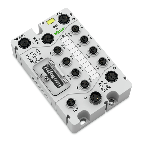
Page 23: Connectors
Figure 1: Connectors Pos : 20.11 /Serie 767 ( WAGO-SPEED WAY)/Gerätebeschr eibung/Ansc hlüs se/Fel dbus koppl er/Legende 767- 1201, - 1301, - 2301 ETHERN ET-Ansc hlus s_1 @ 8\mod_1279266390356_21.doc x @ 60110 @ @ 1 Table 3: Legend for figure “Connectors”... -
Page 24: Marking Possibilities And Fastening
Figure 2: Marking possibilities and fastening Pos : 20.15 /Serie 767 ( WAGO-SPEED WAY)/Gerätebeschr eibung/Befestigung/F eldbus koppler/Leg ende z u Bes chriftung und Befes tigung 767- xxxx_F eldbus koppler @ 7\mod_1268815785576_21.doc x @ 52925 @ @ 1 Table 4: Legend for figure “Marking possibilities and fastening”... -
Page 25: Display Elements
Pos : 20.19 /Serie 767 ( WAGO-SPEED WAY)/Gerätebeschr eibung/Anz eigeel emente/F eldbus koppler /Legende zu Anzeig eel emente 767- xxxx, Pos. 15- 19: Status SBM, F, D I, U A und ULS @ 7\mod_1268815898392_21.doc x @ 52953 @ @ 1... - Page 26 767-1201 FC PROFINET IO 8DI 24V DC Pos : 20.22 /Serie 767 ( WAGO-SPEED WAY)/Gerätebeschr eibung/Anz eigeel emente/F eldbus koppler /Legende zu Anzeig eel emente 767-1201, Pos . 21: Status F eldbus + Hi nweis @ 8\mod_1279270074095_21.doc x @ 60146 @ @ 1...
-
Page 27: Operating Elements
Operating Elements Pos : 20.25 /Serie 767 ( WAGO-SPEED WAY)/Gerätebeschr eibung/Bedi enel emente/F eldbus koppler/Di p-Sc halter 767- 1201, Einl eitung, Default-T abelle, Bil d und Legende @ 8\mod_1279277150324_21.doc x @ 60185 @ @ 1 The DIP switch is used to set the PROFINET station name for the fieldbus coupler. -
Page 28: Table 7: Explanation Of Dip Switch
1 through 7. You have the choice between two station names. When the switch is in the “Off” position, the fieldbus coupler loads the name “wago-767-1201”; when in the “On” position, it loads the name “wagox767x1201”. -
Page 29: Labeling
Pos : 20.27 /Alle Serien (Allgemeine M odul e)/Übersc hriften/Neue Ü bersc hriften/Ebene 2Bedruc kung - Übersc hrift 2 @ 4\mod_1241082409515_21.doc x @ 32035 @ 2 @ 1 Labeling Pos : 20.28 /Serie 767 ( WAGO-SPEED WAY)/Gerätebeschr eibung/Bedr uc kung/F el dbus koppl er/Bedr uc kung 767- 1201 - Bild @ 8\mod_1279274732137_21.doc x @ 60150 @ @ 1 Figure 5: Labeling on the Back Side Pos : 20.29 /Serie 767 ( WAGO-SPEED WAY)/Gerätebeschr eibung/Bedr uc kung/F el dbus koppl er/Bedr uc kung Rüc kseite - Legende @ 7\mod_1268815939674_21.doc x @ 52973 @ @ 1... -
Page 30: Figure 6: Label On Fieldbus Coupler
• Manufacturing number (52) Pos : 20.34 /Serie 767 ( WAGO-SPEED WAY)/Gerätebeschr eibung/Bedr uc kung/F el dbus koppl er/Bedr uc kung seitlic h_MAC-ID - Bild @ 8\mod_1279276081583_21.doc x @ 60175 @ @ 1 Figure 6: Label on fieldbus coupler Pos : 20.35 /Serie 767 ( WAGO-SPEED WAY)/Gerätebeschr eibung/Bedr uc kung/I/O-M odul e/Bedruc kung sei tlich - Legende @ 9\mod_1286969974465_21.doc x @ 65601 @ @ 1... -
Page 31: Schematic Diagram
Schematic Diagram Pos : 20.38 /Serie 767 ( WAGO-SPEED WAY)/Gerätebeschr eibung/Sc hematis che Sc haltbilder/F eldbus koppler/Einl eitung z um schematisc hen Sc haltbild FBK @ 10\mod_1308561496197_21.doc x @ 73710 @ @ 1 The following schematic diagram provides an overview of the power supply and principle of operation of the power supply connections, as well as the digital inputs of the fieldbus coupler (see also section “Connecting the Supply Cable”... -
Page 32: Dimensions
Pos : 20.41 /Alle Serien (Allgemeine M odul e)/Übersc hriften/Neue Ü bersc hriften/Ebene 2Abmess ung en - Übersc hrift 2 @ 5\mod_1248869612468_21.doc x @ 39441 @ 2 @ 1 Dimensions Pos : 20.42 /Serie 767 ( WAGO-SPEED WAY)/Gerätebeschr eibung/Abmessungen/F eldbus koppler/Abmes sungen - Bild @ 7\mod_1268815951549_21.doc x @ 52977 @ @ 1 Figure 8: Dimensions of fieldbus coupler in mm Pos : 20.43 /D okumentati on allgemei n/Gli ederungsel emente/---Seitenwec hs el--- @ 3\mod_1221108045078_0.doc x @ 21810 @ @ 1... -
Page 33: Technical Data
35.7 mm Length 117 mm Pos : 20.46.2 /Serie 767 ( WAGO-SPEEDWAY)/Gerätebeschr eibung/Tec hnisc he D aten/F eldbus koppler/767- 1201, 1501 Ger ätedaten_2 @ 8\mod_1279278572211_21.doc x @ 60218 @ @ 1 Weight Approx. 377 g Pos : 20.46.3 /Serie 767 ( WAGO-SPEEDWAY)/Gerätebeschr eibung/Tec hnisc he D aten/F eldbus koppler/Sys temdaten 767- 1201 @ 8\mod_1279278562117_21.doc x @ 60204 @ 3 @ 1 4.8.2... -
Page 34: Supply
Wrong connection of inputs No effect Pos : 20.46.11 /Seri e 767 ( WAGO- SPEED WAY)/Ger ätebesc hrei bung/T ec hnis che D aten/Fel dbus koppl er/Par ametri erbare Funkti onen @ 8\mod_1279279041466_21.doc x @ 60241 @ 3 @ 1 Manual... -
Page 35: Configurable Functions
Per module Undervoltage (U Pos : 20.46.13 /Seri e 767 ( WAGO- SPEED WAY)/Ger ätebesc hrei bung/T ec hnis che D aten/Fel dbus koppl er/Proz ess abbild 767-1201 @ 8\mod_1279279994613_21.doc x @ 60271 @ 3 @ 1 4.8.8 Process Image Table 17: Technical Data –... -
Page 36: Service Interface Com
M8 connectors, 4 poles Pos : 20.46.17 /Seri e 767 ( WAGO- SPEED WAY)/Ger ätebesc hrei bung/T ec hnis che D aten/Fel dbus koppl er/Potenti altrennung Fel dbus koppl er @ 17\mod_1380526012369_21.doc x @ 133030 @ 3 @ 1 4.8.11 Isolation Table 20: Technical Data −... -
Page 37: Approvals
Approvals Pos : 20.46.19.2 /Serie 767 ( WAGO- SPEED WAY)/Ger ätebesc hrei bung/Z ulas sungen/Z ulassungen F Bkoppler 767- xxxx Allgemei n, ohne Vari antenangabe - Einl eitung @ 22\mod_1427971356549_21.doc x @ 179556 @ @ 1 The following approvals have been granted to 767-1201 fieldbus coupler: Pos : 20.46.19.3.1 /Alle Seri en (Allgemei ne D okumente) (Allgemei ne M odule)/Z ul ass ungen/Standardz ul assungen/C E ( Konformi täts kennz eichnung) @ 3\mod_1224494777421_21.doc x @ 24276 @ @ 1... -
Page 38: Standards And Guidelines
Pos : 20.46.22 /Seri e 767 ( WAGO- SPEED WAY)/Ger ätebesc hrei bung/N or men und Ric htli nien/N ormen und Ric htli nien F Bkoppler 767- xxxx, ohne Vari antenangabe - Einl eitung @ 22\mod_1427980077491_21.doc... -
Page 39: Mounting
Mounting Pos : 23.1 /Serie 767 (WAGO-SPEED WAY)/M ontier en/Fel dbus koppl er/Montage_Ei nlei tung 767- xxxx_Fel dbus koppl er @ 7\mod_1268894154609_21.doc x @ 53410 @ @ 1 The fieldbus coupler can be fastened directly to your system using screws. It can also be mounted on a carrier rail using an adapter (WAGO accessory) or fastened to a profile rail using a surface mounting profile (WAGO accessory). - Page 40 WAGO-SPEEDWAY 767 767-1201 FC PROFINET IO 8DI 24V DC Pos : 23.4 /Serie 767 (WAGO-SPEED WAY)/M ontier en/Fel dbus koppl er/Hinweis: Montage_Ei nbaulage_767- xxxx_F eldbus koppler @ 22\mod_1428401607650_21.doc x @ 179732 @ @ 1 Any mounting position is possible. Ensure a safe mounting position! In explosion hazardous environments no increased mechanical loads must be present at the installation location.
-
Page 41: Tools And Accessories Required For Mounting
767-1201 FC PROFINET IO 8DI 24V DC Pos : 23.6 /Serie 767 (WAGO-SPEED WAY)/M ontier en/Fel dbus koppl er/Montage_Wer kz eug 767- xxxx_Fel dbus koppl er @ 7\mod_1268894155891_21.doc x @ 53422 @ 2 @ 1 Tools and Accessories Required for Mounting Depending on the mounting type, the following tools are required for installation: •... -
Page 42: Direct Mounting On Your System
M4x12 screws via the three mounting holes. Pos : 23.11 /Serie 767 ( WAGO-SPEED WAY)/Monti eren/F eldbus koppler/M ontage_Dir ektmontag e 767- xxxx_F eldbus koppler - Bild @ 7\mod_1268894152578_21.doc x @ 53390 @ @ 1 Figure 9: Mounting the fieldbus coupler on the grounded system Pos : 23.12 /D okumentati on allgemei n/Gli ederungsel emente/---Seitenwec hs el--- @ 3\mod_1221108045078_0.doc x @ 21810 @ @ 1... -
Page 43: Mounting On A Carrier Rail (Only With Wago Accessories)
Pos : 23.14 /Serie 767 ( WAGO-SPEED WAY)/Monti eren/F eldbus koppler/M ontage auf Tr agschi ene 767- xxxx_F eldbus koppler - Bil d @ 7\mod_1268894149734_21.doc x @ 53362 @ @ 1 Figure 10: Fastening the fieldbus coupler to the carrier rail adapter Pos : 23.15 /D okumentati on allgemei n/Gli ederungsel emente/---Seitenwec hs el--- @ 3\mod_1221108045078_0.doc x @ 21810 @ @ 1... -
Page 44: Fastening The Fieldbus Coupler With Carrier Rail Adapter To A Carrier Rail
(item no.: 249-116 or 249-117) for stabilization is required. Pos : 23.17 /Serie 767 ( WAGO-SPEED WAY)/Monti eren/F eldbus koppler/M ontage_Befestigung auf Tragsc hienenadapter 767- xxxx_Fel dbus koppl er - Bild @ 7\mod_1268905883023_21.doc x @ 53430 @ @ 1 Figure 11: Mounting the carrier rail adapter Pos : 23.18 /D okumentati on allgemei n/Gli ederungsel emente/---Seitenwec hs el--- @ 3\mod_1221108045078_0.doc x @ 21810 @ @ 1... -
Page 45: Mounting On A Profile Rail (Only With Wago Accessories)
Pos : 23.20 /Serie 767 ( WAGO-SPEED WAY)/Monti eren/F eldbus koppler/M ontage an ei ner Pr ofilsc hiene 767-xxxx_Fel dbus koppl er - Bild @ 7\mod_1268894148922_21.doc x @ 53354 @ @ 1 Figure 12: Fastening the fieldbus coupler to the profile adapter Pos : 23.21 /D okumentati on allgemei n/Gli ederungsel emente/---Seitenwec hs el--- @ 3\mod_1221108045078_0.doc x @ 21810 @ @ 1... -
Page 46: Fastening The Fieldbus Coupler With Profile Adapter To A Profile Rail
767-1201 FC PROFINET IO 8DI 24V DC Pos : 23.22 /Serie 767 ( WAGO-SPEED WAY)/Monti eren/F eldbus koppler/M ontage mit Pr ofiladapter an ei ner Pr ofilsc hiene 767-xxxx_Fel dbus koppl er @ 7\mod_1268894150094_21.doc x @ 53366 @ 3 @ 1 5.5.2... -
Page 47: Replacing The Marker Card And Strip
New cards, strips and pens can be obtained from WAGO. Pos : 23.25 /Serie 767 ( WAGO-SPEED WAY)/Monti eren/F eldbus koppler/M ontage_Besc hriftung austausc hen 767- xxxx_Fel dbus koppl er - Bild @ 7\mod_1268894151750_21.doc x @ 53382 @ @ 1 Figure 13: Replacing the marker card and strip Pos : 23.26 /D okumentati on allgemei n/Gli ederungsel emente/---Seitenwec hs el--- @ 3\mod_1221108045078_0.doc x @ 21810 @ @ 1... -
Page 48: Mounting The Spacer In The Case Of Compact Arrangement
M4 screws via the mounting holes. Pos : 23.28 /Serie 767 ( WAGO-SPEED WAY)/Monti eren/F eldbus koppler/M ontage_Di stanzs tüc k T eil 1_767- xxxx_F eldbus koppler - Bild @ 7\mod_1268894153437_21.doc x @ 53398 @ @ 1 Figure 14: Attaching a spacer Pos : 23.29 /D okumentati on allgemei n/Gli ederungsel emente/---Seitenwec hs el--- @ 3\mod_1221108045078_0.doc x @ 21810 @ @ 1... -
Page 49: Figure 15: Attaching Another 767 Component To The Fieldbus Coupler
Pos : 23.31 /Serie 767 ( WAGO-SPEED WAY)/Monti eren/F eldbus koppler/M ontage_Di stanzs tüc k T eil 2_767- xxxx_F eldbus koppler - Bild @ 7\mod_1268894154219_21.doc x @ 53406 @ @ 1 Figure 15: Attaching another 767 component to the fieldbus coupler Pos : 24 /D okumentation allgemei n/Glieder ungs elemente/---Seitenwechs el--- @ 3\mod_1221108045078_0.doc x @ 21810 @ @ 1... -
Page 50: Connecting Data And Supply Cables
767-1201 FC PROFINET IO 8DI 24V DC Pos : 25.1 /Serie 767 (WAGO-SPEED WAY)/Ans chl uss D aten- und Vers orgungs kabel/I/O-Modul e/01_Ansc hl uss der Daten- und Vers orgungs kabel - Übersc hrift 1 @ 8\mod_1278310189976_21.doc x @ 58919 @ 1 @ 1 Connecting Data and Supply Cables Pos : 25.2 /Serie 767 (WAGO-SPEED WAY)/Ans chl uss D aten- und Vers orgungs kabel/I/O-Modul e/02_Hinweis e - Ü... -
Page 51: Required Accessories
Observe the correct layout of the potential equalization. Pos : 25.8 /Serie 767 (WAGO-SPEED WAY)/Ans chl uss D aten- und Vers orgungs kabel/Fel dbus koppl er/Ansc hluss_Hi nweise Teil 3 (nic ht 767- 1401) @ 7\mod_1268909851033_21.doc x @ 53534 @ @ 1 •... -
Page 52: Connecting The Fieldbus Cable
767-1201 FC PROFINET IO 8DI 24V DC Pos : 25.11 /Serie 767 ( WAGO-SPEED WAY)/Ansc hluss D aten- und Versorgungs kabel/F eldbus koppler/0_Ansc hlus s_F eldbus kabel anschli eßen - Übersc hrift 2 @ 8\mod_1281001995154_21.doc x @ 62338 @ 2 @ 1 Connecting the Fieldbus Cable Pos : 25.12 /Serie 767 ( WAGO-SPEED WAY)/Ansc hluss D aten- und Versorgungs kabel/F eldbus koppler/Ansc hluss _ETHERN ET-Kabel 767- 1201 Ei nlei tung @ 8\mod_1279518663025_21.doc x @ 60306 @ @ 1... -
Page 53: Connecting A Fieldbus Coupler To An Ethernet Network
WAGO-SPEEDWAY 767 Connecting Data and Supply Cables 767-1201 FC PROFINET IO 8DI 24V DC 6.3.1 Connecting a Fieldbus Coupler to an ETHERNET Network To connect the fieldbus coupler to an ETHERNET network, proceed as follows: Disconnect the power supply from those devices on which you have mounted the fieldbus coupler. -
Page 54: Figure 17: Example Setup Of A Mixed Topology With Four Fieldbus Couplers
Connecting Data and Supply Cables WAGO-SPEEDWAY 767 767-1201 FC PROFINET IO 8DI 24V DC Figure 17: Example setup of a mixed topology with four fieldbus couplers For a line topology, connect the ETHERNET cables (W3, W4) with the connections IN... -
Page 55: Figure 18: Example Setup Of A Mixed Topology With Four Fieldbus Couplers
WAGO-SPEEDWAY 767 Connecting Data and Supply Cables 767-1201 FC PROFINET IO 8DI 24V DC Figure 18: Example setup of a mixed topology with four fieldbus couplers Pos : 25.14 /D okumentati on allgemei n/Gli ederungsel emente/---Seitenwec hs el--- @ 3\mod_1221108045078_0.doc x @ 21810 @ @ 1 Manual Version 2.2.0... -
Page 56: Connecting The S-Bus Cable
WAGO-SPEEDWAY 767 767-1201 FC PROFINET IO 8DI 24V DC Pos : 25.15 /Serie 767 ( WAGO-SPEED WAY)/Ansc hluss D aten- und Versorgungs kabel/F eldbus koppler/Ansc hluss _S-BUS allgemein @ 7\mod_1268906368415_21.doc x @ 53454 @ 2 @ 1 Connecting the S-BUS Cable The S-BUS is used for communication between the fieldbus coupler and the connected I/O modules. -
Page 57: Figure 19: S-Bus Is Connected To One Fieldbus Coupler And Two I/O Modules
Pos : 25.16 /Serie 767 ( WAGO-SPEED WAY)/Ansc hluss D aten- und Versorgungs kabel/F eldbus koppler/Ansc hluss _S-BUS ETH ERN ET-Fel dbus koppl er @ 8\mod_1279802895669_21.doc x @ 60854 @ @ 1 If you do not connect any I/O modules to the S-BUS, screw the S-BUS terminator (T) onto the S-BUS OUT output (3) of the fieldbus coupler. -
Page 58: Connecting The Supply Cable
767-1201 FC PROFINET IO 8DI 24V DC Pos : 25.19 /Serie 767 ( WAGO-SPEED WAY)/Ansc hluss D aten- und Versorgungs kabel/F eldbus koppler/Ansc hluss _Spannungs vers orgung @ 7\mod_1268906369493_21.doc x @ 53462 @ 2 @ 1 Connecting the Supply Cable The supply cable provides power to the fieldbus coupler and the connected I/O modules. -
Page 59: Figure 20: Supply Cable Connected With Fieldbus Coupler And I/O Modules
Tighten the plugs and sockets using the knurled-head screw. Pos : 25.20 /Serie 767 ( WAGO-SPEED WAY)/Ansc hluss D aten- und Versorgungs kabel/F eldbus koppler/Ansc hluss _Spannungs vers orgung - Bild @ 7\mod_1268906370024_21.doc x @ 53466 @ @ 1 Figure 20: Supply cable connected with fieldbus coupler and I/O modules Pos : 25.21 /D okumentati on allgemei n/Gli ederungsel emente/---Seitenwec hs el--- @ 3\mod_1221108045078_0.doc x @ 21810 @ @ 1... -
Page 60: Connecting The Sensor Cables
X1, X3, X5, X7 X2, X4, X6, X8 Pos : 25.23 /Serie 767 ( WAGO-SPEED WAY)/Wichtige Erläuter ung en/Sic herheits hinweise/Ac htung/Ac htung: Höchs te Strombel astbar bei t der Vers .kontakte( Sens oren) und Sens orstromaufnahme 400 mA @ 8\mod_1278305007084_21.doc x @ 58890 @ @ 1... -
Page 61: Figure 21: Digital Inputs
Screw a protective cap on all unused input sockets to ensure that IP67 degree of protection is provided. Pos : 25.26 /Serie 767 ( WAGO-SPEED WAY)/Ansc hluss D aten- und Versorgungs kabel/F eldbus koppler/Ansc hluss _Sens oren - Bild @ 7\mod_1268906365883_21.doc x @ 53434 @ @ 1 Figure 21: Digital inputs Pos : 25.27 /D okumentati on allgemei n/Gli ederungsel emente/---Seitenwec hs el--- @ 3\mod_1221108045078_0.doc x @ 21810 @ @ 1... -
Page 62: Connecting The Usb Cable
767-1201 FC PROFINET IO 8DI 24V DC Pos : 25.28 /Serie 767 ( WAGO-SPEED WAY)/Ansc hluss D aten- und Versorgungs kabel/F eldbus koppler/Ansc hluss _U SB 1 @ 7\mod_1268916382387_21.doc x @ 53560 @ 2 @ 1 Connecting the USB Cable... -
Page 63: Figure 22: Usb Interface
767-1201 FC PROFINET IO 8DI 24V DC Pos : 25.35 /Serie 767 ( WAGO-SPEED WAY)/Ansc hluss D aten- und Versorgungs kabel/F eldbus koppler/Ansc hluss _U SB 5_2 @ 8\mod_1279087307901_21.doc x @ 59883 @ @ 1 Connect your PC with the fieldbus coupler by inserting the USB cable plug into the fieldbus coupler's USB connection COM (7) and tightening it. -
Page 64: Commissioning
• The shielding is carried out properly. Pos : 27.4 /Serie 767 (WAGO-SPEED WAY)/In Betrieb nehmen/Fel dbus koppl er/Inbetri ebnahme 767-1201, -1301, -1311, - 1401, -1501 @ 8\mod_1279524134190_21.doc x @ 60324 @ @ 1 • The power supply of the higher-level controller is switched on (see associated manual). -
Page 65: Setting The Profinet Station Name
767-1201 FC PROFINET IO 8DI 24V DC Pos : 27.6 /Serie 767 (WAGO-SPEED WAY)/In Betrieb nehmen/Fel dbus koppl er/Ei nstellen der PR OFIN ET-Adress e 767- 1201 @ 8\mod_1279524647757_21.doc x @ 60338 @ 2 @ 1 Setting the PROFINET Station Name To operate the PROFINET fieldbus coupler in a network, it must be assigned a unique name. -
Page 66: Figure 23: Dip Switch Set For Instance 52
I/O controller after fieldbus coupler identification. In the following example, switches 3, 5 and 6 are switched on (switch 8 is off!). Thus, the new station address of the “wago-767-1201-52” fieldbus coupler is as follows (2 = 4 + 16 + 32 = 52). -
Page 67: Switching On The Fieldbus Coupler
Commissioning 767-1201 FC PROFINET IO 8DI 24V DC Pos : 27.8 /Serie 767 (WAGO-SPEED WAY)/In Betrieb nehmen/Fel dbus koppl er/Ei nsc hal ten 767- 1201 @ 8\mod_1279527198130_21.doc x @ 60345 @ 2 @ 1 Switching on the Fieldbus Coupler The fieldbus coupler starts running immediately when the power supply is switched on. -
Page 68: The Web-Based Management (Wbm)
An Internet browser is needed in order to use the WBM. Enter the IP address of the fieldbus coupler into the address bar (e.g., http://192.168.1.100). Pos : 30 /Serie 767 ( WAGO-SPEED WAY)/Wic htige Erläuterungen/Sicherheits hinweis e/Hi nweis /Hinweis: 767- 1201 Hinweis zum WBM @ 8\mod_1279528827228_21.doc x @ 60365 @ @ 1 IP Address... -
Page 69: Information" View
WAGO-SPEEDWAY 767 Commissioning 767-1201 FC PROFINET IO 8DI 24V DC Pos : 33 /Serie 767 ( WAGO-SPEED WAY)/Konfiguri eren/F eldbus koppler/WBM 767-1201 Startbild allgemein @ 12\mod_1334846712749_21.doc x @ 93880 @ 3 @ 1 7.3.1 “Information” View After entering the IP address, the start page “Information” appears from the web- based management. -
Page 70: Ethernet" View
Commissioning WAGO-SPEEDWAY 767 767-1201 FC PROFINET IO 8DI 24V DC 7.3.2 “ETHERNET” View The “ETHERNET” page contains information about the physical connection to the connected ETHERNET network. The value displayed cannot be changed. The following table explains the parameters listed on the site: Table 28: Parameter description of the page “ETHERNET”... -
Page 71: Tcp/Ip" View
WAGO-SPEEDWAY 767 Commissioning 767-1201 FC PROFINET IO 8DI 24V DC 7.3.3 “TCP/IP” View This page displays the TCP/IP settings. You can use a project tool to change the configuration via the DCP protocol. The following table explains the parameters listed on the site: Table 29: Parameter description of the page “TCP/IP”... -
Page 72: Snmp" View
WAGO 0767-1201 Device name (sysName) FC PROFINET IO System Location Location of device (sysLocation) local (physical) System Contact support@wago.com E-mail contact address (sysContact) SNMP V1/V2 Manager Configuration Entry Value (Default) Description Activating SNMP Version 1/2c SNMP Protocol Enable ... -
Page 73: Snmp V3" View
WAGO-SPEEDWAY 767 Commissioning 767-1201 FC PROFINET IO 8DI 24V DC 7.3.6 “SNMP V3” View The SNMP V3 network characteristics are configured on this page. To confirm your entries, click [SUBMIT]. To clear your entries, click [RESET]. Your entries are not active until the software has been reset. To reset the software, click on “Administration”... -
Page 74: Clock" View
Commissioning WAGO-SPEEDWAY 767 767-1201 FC PROFINET IO 8DI 24V DC 7.3.7 “Clock” View On this page, the real-time clock is configured. The time and date can only be changed as user admin and user. To clear your entries, click [RESET]. -
Page 75: Administration" View
WAGO-SPEEDWAY 767 Commissioning 767-1201 FC PROFINET IO 8DI 24V DC 7.3.9 “Administration” View On this page, you can reset the software or reset all parameters to the default status. You can only use these functions if you are logged on as the “admin” user. -
Page 76: Configuration
Pos : 36 /All e Seri en (Allgemei ne Module)/Ü berschriften/N eue Ü berschriften/Ebene 1Konfig urieren - Ü berschrift 1 @ 5\mod_1247578046546_21.doc x @ 37410 @ 1 @ 1 Configuration Pos : 37 /Serie 767 ( WAGO-SPEED WAY)/Konfiguri eren/F eldbus koppler/Konfig urieren_767- 1201 @ 8\mod_1279530175853_21.doc x @ 60371 @ 223 @ 1 This section contains all information required for configuration of the 767 components for PROFINET IO. -
Page 77: Gsdml File
IO Controller and the fieldbus coupler for the active data exchange. The GSDML file can be obtained at www.wago.com. When installing this file, please refer to the information provided in the documentation of the configuration software which you are using. The GSDML file is imported and installed from the configuration software. -
Page 78: Table 34: Compatibility Of Field Bus Couplers Version R3/R5 And The Gsdml Files
Configuration WAGO-SPEEDWAY 767 767-1201 FC PROFINET IO 8DI 24V DC Table 34: Compatibility of field bus couplers version R3/R5 and the GSDML files Property Field bus coupler version R5 Field bus coupler Version R3 R5-GSDML R3-GSDML R3-GSDML GSDML version 2.25... -
Page 79: Parameterizing
Pos : 39 /All e Seri en (Allgemei ne Module)/Ü berschriften/N eue Ü berschriften/Ebene 1Par ametrieren - Übersc hrift 1 @ 3\mod_1223554593484_21.doc x @ 23717 @ 1 @ 1 Parameterizing Pos : 40 /Serie 767 ( WAGO-SPEED WAY)/F eldbus kommuni kation/Par ametrierung 767-1201 @ 8\mod_1279530336890_21.doc x @ 60375 @ 2233334443444333444443333 @ 1 This section contains essential information for the parameterization of the 767 components, such as responding correctly in case of error and enabling diagnostic messages. -
Page 80: Parameterization Of The Fieldbus Coupler
Parameterizing WAGO-SPEEDWAY 767 767-1201 FC PROFINET IO 8DI 24V DC Parameterization of the Fieldbus Coupler The following properties can be parameterized for the entire node via the fieldbus coupler (default values in italics): Table 35: Parameterization data of the fieldbus coupler... -
Page 81: Parameters Of The I/O Modules
WAGO-SPEEDWAY 767 Parameterizing 767-1201 FC PROFINET IO 8DI 24V DC Parameters of the I/O Modules The following is a description of all adjustable properties of the I/O modules of the 767 system (preset values in italics): 9.2.1 8-Channel Digital Input Modules... -
Page 82: 8-Channel Digital Output Modules (767-4801, 767-4802, 767-4803, 767-4804, 0767-4801/0000-0800, 0767-4802/0000-0800, 0767-4803/0000-0800, 0767-4804/0000-0800)
Parameterizing WAGO-SPEEDWAY 767 767-1201 FC PROFINET IO 8DI 24V DC 9.2.2 8-Channel Digital Output Modules (767-4801, 767-4802, 767-4803, 767-4804, 0767-4801/0000-0800, 0767-4802/0000-0800, 0767-4803/0000-0800, 0767-4804/0000-0800) The following settings can be applied to the digital output modules (preset values in italics): Table 38: Parameters of the 8DO module... -
Page 83: Ttl Incremental/Ssi Encoder Interface (767-5201)
WAGO-SPEEDWAY 767 Parameterizing 767-1201 FC PROFINET IO 8DI 24V DC 9.2.4 TTL Incremental/SSI Encoder Interface (767-5201) The following settings can be applied to the TTL Incremental/SSI Encoder Interface (preset values in italics): 9.2.4.1 Function with 2 Incremental Encoders Table 40: Parameter function with 2 Incremental Encoders... -
Page 84: Table 40: Parameter Function With 2 Incremental Encoders
Parameterizing WAGO-SPEEDWAY 767 767-1201 FC PROFINET IO 8DI 24V DC Table 40: Parameter function with 2 Incremental Encoders Parameter Description Channel 2.1 Diagnostics disabled enabled Operating mode Digital input Digital output Filter time [ms] deactivated 0.065 0.25 Substitute strategy Set substitute value... - Page 85 WAGO-SPEEDWAY 767 Parameterizing 767-1201 FC PROFINET IO 8DI 24V DC Table 40: Parameter function with 2 Incremental Encoders Parameter Description Channel 3 – Incremental-Encoder 1 / Channel 4 – Incremental-Encoder 2 Diagnostics Counter disabled enabled Input Latch via DI 1...
-
Page 86: Function With 2 Ssi Encoders
Parameterizing WAGO-SPEEDWAY 767 767-1201 FC PROFINET IO 8DI 24V DC 9.2.4.2 Function with 2 SSI Encoders Table 41: Parameter function with 2 SSI Encoders Parameter Description Module Diagnostics field supply channel 1, 2 disabled enabled Diagnostics field supply channel 3, 4... - Page 87 WAGO-SPEEDWAY 767 Parameterizing 767-1201 FC PROFINET IO 8DI 24V DC Table 41: Parameter function with 2 SSI Encoders Parameter Description Set substitute value Substitute strategy Keep last value Substitute value PWM Output / Frequency [Hz] deactivated Channel 2.2 Diagnostics disabled...
-
Page 88: Table 41: Parameter Function With 2 Ssi Encoders
Parameterizing WAGO-SPEEDWAY 767 767-1201 FC PROFINET IO 8DI 24V DC Table 41: Parameter function with 2 SSI Encoders Parameter Description Evaluation alarmbit Parity None Even Encoding format Binary Gray SSI Encoder 1 SSI Encoder 2 Manual Version 2.2.0... -
Page 89: Function With 1 Incremental Encoder And 1 Ssi Encoder
WAGO-SPEEDWAY 767 Parameterizing 767-1201 FC PROFINET IO 8DI 24V DC 9.2.4.3 Function with 1 Incremental Encoder and 1 SSI Encoder Table 42: Parameter function with 1 Incremental Encoder and 1 SSI Encoder Parameter Description Module Diagnostics field supply channel 1, 2... - Page 90 Parameterizing WAGO-SPEEDWAY 767 767-1201 FC PROFINET IO 8DI 24V DC Table 42: Parameter function with 1 Incremental Encoder and 1 SSI Encoder Parameter Description Set substitute value Substitute strategy Keep last value Substitute value PWM Output / Frequency [Hz] deactivated Channel 2.2...
- Page 91 WAGO-SPEEDWAY 767 Parameterizing 767-1201 FC PROFINET IO 8DI 24V DC Table 42: Parameter function with 1 Incremental Encoder and 1 SSI Encoder Parameter Description 4-fold evaluation Channel 4 – SSI Encoder 1 Diagnostics SSI disabled enabled Diagnostics Counter disabled enabled...
-
Page 92: Htl Incremental Encoder/ Counter Interface (767-5202)
Parameterizing WAGO-SPEEDWAY 767 767-1201 FC PROFINET IO 8DI 24V DC 9.2.5 HTL Incremental Encoder/ Counter Interface (767-5202) The following settings can be applied to the HTL Incremental Encoder/ Counter Interface (preset values in italics): 9.2.5.1 Function with 2 Counters Table 43: Parameter function with 2 Counters... - Page 93 WAGO-SPEEDWAY 767 Parameterizing 767-1201 FC PROFINET IO 8DI 24V DC Table 43: Parameter function with 2 Counters Parameter Description deactivated Filter time [ms] 0.065 0.25 Substitute strategy Set substitute value Keep last value Substitute value PWM Output / Frequency [Hz] deactivated Channel 2.2...
-
Page 94: Table 43: Parameter Function With 2 Counters
Parameterizing WAGO-SPEEDWAY 767 767-1201 FC PROFINET IO 8DI 24V DC Table 43: Parameter function with 2 Counters Parameter Description Gate time [ms] 1000 Input counter direction via DI 5 DI 7 Counter 1 Counter 2 Manual Version 2.2.0... -
Page 95: Function With 2 Incremental Encoders
WAGO-SPEEDWAY 767 Parameterizing 767-1201 FC PROFINET IO 8DI 24V DC 9.2.5.2 Function with 2 Incremental Encoders Table 44: Parameter function with 2 Incremental Encoders Parameter Description Module Diagnostics field supply channel 1, 2 disabled enabled Diagnostics field supply channel 3, 4... - Page 96 Parameterizing WAGO-SPEEDWAY 767 767-1201 FC PROFINET IO 8DI 24V DC Table 44: Parameter function with 2 Incremental Encoders Parameter Description Set substitute value Substitute strategy Keep last value Substitute value PWM Output / Frequency [Hz] deactivated Channel 2.2 Diagnostics disabled...
- Page 97 WAGO-SPEEDWAY 767 Parameterizing 767-1201 FC PROFINET IO 8DI 24V DC Table 44: Parameter function with 2 Incremental Encoders Parameter Description 4-fold evaluation Encoder 1 Encoder 2 Manual Version 2.2.0...
-
Page 98: Function With 1 Counter And 1 Incremental Encoder
Parameterizing WAGO-SPEEDWAY 767 767-1201 FC PROFINET IO 8DI 24V DC 9.2.5.3 Function with 1 Counter and 1 Incremental Encoder Table 45: Parameter function with 1 Counter and 1 Incremental Encoder Parameter Description Module Diagnostics field supply channel 1, 2 disabled... - Page 99 WAGO-SPEEDWAY 767 Parameterizing 767-1201 FC PROFINET IO 8DI 24V DC Table 45: Parameter function with 1 Counter and 1 Incremental Encoder Parameter Description Set substitute value Substitute strategy Keep last value Substitute value PWM Output / Frequency [Hz] deactivated Channel 2.2...
- Page 100 Parameterizing WAGO-SPEEDWAY 767 767-1201 FC PROFINET IO 8DI 24V DC Table 45: Parameter function with 1 Counter and 1 Incremental Encoder Parameter Description Channel 4 – Incremental Encoder 1 Diagnostics Counter disabled enabled Input Latch via DI 1 via DI 3...
-
Page 101: Serial Interface (767-5203)
WAGO-SPEEDWAY 767 Parameterizing 767-1201 FC PROFINET IO 8DI 24V DC 9.2.6 Serial Interface (767-5203) The following settings can be applied to the Serial Interface (preset values in italics): Parameter Combinations Not all parameter combinations are valid. More information about valid parameterizations is available in the respective I/O module manual. -
Page 102: Movilink Interface (767-5204)
Parameterizing WAGO-SPEEDWAY 767 767-1201 FC PROFINET IO 8DI 24V DC 9.2.7 MOVILINK Interface (767-5204) The following settings can be applied to the MOVILINK Interface (preset values in italics): Parameter Combinations Not all parameter combinations are valid. More information about valid parameterizations is available in the respective I/O module manual. -
Page 103: Dio Module With 8 Channels (767-5801, 767-5802, 767-5803, 0767-5801/0000-0800, 0767-5802/0000-0800, 0767-5803/0000-0800)
WAGO-SPEEDWAY 767 Parameterizing 767-1201 FC PROFINET IO 8DI 24V DC 9.2.8 DIO Module with 8 Channels (767-5801, 767-5802, 767-5803, 0767-5801/0000-0800, 0767-5802/0000-0800, 0767-5803/0000-0800) Delay in Establishing the Connection After the function mode of one or more 580x modules has been changed, it can take several seconds to establish a connection when first establishing communication with a fieldbus controller. -
Page 104: Operating Mode Dio: Combined Operation Of Digital Input- And -Output Module
Parameterizing WAGO-SPEEDWAY 767 767-1201 FC PROFINET IO 8DI 24V DC 9.2.8.3 Operating mode DIO: Combined Operation of Digital Input- and -Output module Table 50: Parameters for operation as Digital Input- and -Output module Parameter Description Diagnostics: Short circuit field supply... -
Page 105: Operating Mode Dio + 1 Counter: Combined Operation Of Digital Input- And -Output Module With 1 Counter
WAGO-SPEEDWAY 767 Parameterizing 767-1201 FC PROFINET IO 8DI 24V DC 9.2.8.4 Operating mode DIO + 1 Counter: Combined Operation of Digital Input- and -Output module with 1 Counter Table 51: Parameters for operation as Digital Input- and –Output module with 1 Counter... -
Page 106: Operating Mode Dio + 2 Counters: Combined Operation Of Digital Input- And -Output Modules With 2 Counters
Parameterizing WAGO-SPEEDWAY 767 767-1201 FC PROFINET IO 8DI 24V DC 9.2.8.5 Operating mode DIO + 2 Counters: Combined Operation of Digital Input- and –Output modules with 2 Counters Table 52: Parameters for operation as Digital Input- and –Output modules with 2 Counters... -
Page 107: 4-Channels Analog Input Modules Voltage/Current (767-6401)
WAGO-SPEEDWAY 767 Parameterizing 767-1201 FC PROFINET IO 8DI 24V DC 9.2.9 4-Channels Analog Input Modules Voltage/Current (767-6401) The following settings can be applied to the analog input modules voltage/current (default values in italics): Table 53: Parameters of the 4AI U/I modules... -
Page 108: 4-Channel Rtd Analog Input Modules (767-6402)
Parameterizing WAGO-SPEEDWAY 767 767-1201 FC PROFINET IO 8DI 24V DC 9.2.10 4-Channel RTD Analog Input Modules (767-6402) The following settings can be applied to the RTD analog input modules (default values in italics): Table 54: Parameters of the 4AI RTD Modules... -
Page 109: 4-Channel Tc Analog Input Modules (767-6403)
WAGO-SPEEDWAY 767 Parameterizing 767-1201 FC PROFINET IO 8DI 24V DC 9.2.11 4-Channel TC Analog Input Modules (767-6403) The following settings can be applied to the TC analog input modules: Table 55: Parameters of the 4AI TC Modules Parameter Description Module... -
Page 110: 4-Channel Analog Output Modules Voltage/Current (767-7401)
Parameterizing WAGO-SPEEDWAY 767 767-1201 FC PROFINET IO 8DI 24V DC 9.2.12 4-Channel Analog Output Modules Voltage/Current (767-7401) The following settings can be applied to the analog output modules (default values in italics): Table 56: Parameters of the 4AO U/I modules... -
Page 111: Acyclic Services
Acyclic Services 767-1201 FC PROFINET IO 8DI 24V DC Pos : 42 /Serie 767 ( WAGO-SPEED WAY)/F eldbus kommuni kation/Az yklisc he Dienste 767- 1201 @ 8\mod_1279530810250_21.doc x @ 60392 @ 1222 @ 1 Acyclic Services Using acyclic services, you can read out or modify information of the fieldbus coupler and the connected I/O modules. -
Page 112: I&M Services
Acyclic Services WAGO-SPEEDWAY 767 767-1201 FC PROFINET IO 8DI 24V DC 10.1 I&M Services The information available in the 767 components is not only relevant for the actual automation function, but are also used by various applications during the entire life cycle. Of particular significance is data that is pertinent to service and maintenance processes. - Page 113 WAGO-SPEEDWAY 767 Acyclic Services 767-1201 FC PROFINET IO 8DI 24V DC Hardware version … 0x0002: Hardware version Software prefix Official release version Software functionality Level of development Troubleshooting Error status Modifications Correction status Version counter … 0x0001: Series of version Profile identification 52...53...
-
Page 114: Parameter Services
Acyclic Services WAGO-SPEEDWAY 767 767-1201 FC PROFINET IO 8DI 24V DC 10.2 Parameter Services The parameterization of the 767-1201 PROFINET coupler is only possible via the acyclic services, for which the index 4000 is to be used. After configuration of the fieldbus coupler, the IO Controller conveys the parameterization data in order to change the settings of the coupler and the I/O modules according to the configuration. -
Page 115: Operation With 2 Fieldbus Controllers (Shared Device)
767-1201 FC PROFINET IO 8DI 24V DC Pos : 44 /Serie 767 ( WAGO-SPEED WAY)/F eldbus kommuni kation/Betrieb mit 2 C ontroll ern ( Shared D evic e) 767-1201 @ 12\mod_1336050909156_21.doc x @ 94450 @ 1 @ 1 Operation with 2 Fieldbus Controllers... - Page 116 Operation with 2 Fieldbus Controllers (Shared Device) WAGO-SPEEDWAY 767 767-1201 FC PROFINET IO 8DI 24V DC Using Digital Input/Output Modules When using digital input/output modules (e.g., 5801, 5802, 5803), please note that the operating mode of the I/O module is defined in the configuration. It depends on the type of submodule assigned to the I/O module.
-
Page 117: Profinet Io Diagnostics
PROFINET IO Diagnostics 767-1201 FC PROFINET IO 8DI 24V DC Pos : 46 /Serie 767 ( WAGO-SPEED WAY)/F eldbus kommuni kation/PROF INET IO- Stations diag nos e 767- 1201 @ 8\mod_1281013835245_21.doc x @ 62470 @ 122222 @ 1 PROFINET IO Diagnostics This section contains all information required to analyze the diagnostic information of the 767 components for PROFINET IO. - Page 118 PROFINET IO Diagnostics WAGO-SPEEDWAY 767 767-1201 FC PROFINET IO 8DI 24V DC The disruptions can be indicated with the help of the configuration tool that you used to create your project. According to the information from the GSDML file, the disruptions are textually displayed. The diagnostic data of a disruption is...
- Page 119 WAGO-SPEEDWAY 767 PROFINET IO Diagnostics 767-1201 FC PROFINET IO 8DI 24V DC Slot (module slot) Coupler module Integrated digital inputs 10, 11 … 64 I/O modules … 65535 Reserved Sub-slot (sub-module slot) Reserved Coupler, I/O module … 32767 Reserved 12, 13...
- Page 120 PROFINET IO Diagnostics WAGO-SPEEDWAY 767 767-1201 FC PROFINET IO 8DI 24V DC Additional diagnostic information Coupler-specific error values (value 0 or 28 – 31 corresponding to expanded error type) Manual Version 2.2.0...
-
Page 121: Table 61: Channel Properties, Type (Bit 0
WAGO-SPEEDWAY 767 PROFINET IO Diagnostics 767-1201 FC PROFINET IO 8DI 24V DC The channel properties are stored in a 16-bit value and defined as follows in accordance with the PROFINET specification: Table 61: Channel properties, type (bit 0 … 7) -
Page 122: Standard Error Types
PROFINET IO Diagnostics WAGO-SPEEDWAY 767 767-1201 FC PROFINET IO 8DI 24V DC Table 65: Channel properties, data direction (bit 13 … 15) Direction Description Manufacturer-specific definition, e.g. with a module-specific diagnostic. This is a channel with input data. This is a channel with output data. -
Page 123: Configuration-Specific Error Types
WAGO-SPEEDWAY 767 PROFINET IO Diagnostics 767-1201 FC PROFINET IO 8DI 24V DC 12.2 Configuration-Specific Error Types The configuration-specific error types describe errors arising with the configuration of the fieldbus coupler and the I/O module. These can include differences between the preset and the actual configuration, resource conflicts, or errors with creating the process image. -
Page 124: Parameterization-Specific Error Types
PROFINET IO Diagnostics WAGO-SPEEDWAY 767 767-1201 FC PROFINET IO 8DI 24V DC 12.3 Parameterization-Specific Error Types The parameterization-specific error types describe errors arising with the parameterization of the fieldbus coupler and the I/O module. These can include invalid data content or faulty access to an I/O module. The expanded error type provides a more specific description of the error. -
Page 125: User-Specific Error Types
WAGO-SPEEDWAY 767 PROFINET IO Diagnostics 767-1201 FC PROFINET IO 8DI 24V DC 12.4 User-Specific Error Types The user-specific error types describe errors that are caused by an internal problem with the fieldbus coupler. These errors are only recorded in the diagnostic memory during parameterization. - Page 126 PROFINET IO Diagnostics WAGO-SPEEDWAY 767 767-1201 FC PROFINET IO 8DI 24V DC Table 69: User-Specific Error Types and description Error type Expanded Description error type 32642 Module busy 32643 Positive fragment acknowledge 32644 Negative fragment acknowledge 32647 Send next fragment...
-
Page 127: Expanded Standard Error Types
WAGO-SPEEDWAY 767 PROFINET IO Diagnostics 767-1201 FC PROFINET IO 8DI 24V DC 12.5 Expanded Standard Error Types Expanded standard error types provided additional information about errors that are not sufficiently described by the standard error types 1 through 9 due to the definitions in the PROFINET specification. -
Page 128: The File System
WAGO-SPEEDWAY 767 767-1201 FC PROFINET IO 8DI 24V DC Pos : 48 /Serie 767 ( WAGO-SPEED WAY)/D ateis ystem/D ateis ys tem 767- 1201, - 1301 @ 8\mod_1279531084905_21.doc x @ 60397 @ 1 @ 1 The File System Two partitions of the file system are available to the user including a RAM disk and a partition in Flash memory. -
Page 129: Access Via Ftp
WAGO-SPEEDWAY 767 The File System 767-1201 FC PROFINET IO 8DI 24V DC 13.2 Access via FTP To access the fieldbus coupler using FTP, proceed as follows: Open the DOS console. Click on the start menu and select “Run”. Enter the command and click [OK]. -
Page 130: Diagnostics
WAGOframe. For more information, see section “Readout of Blink Codes using WAGO DTMs”. Pos : 52.3 /Serie 767 (WAGO-SPEED WAY)/Di agnose/Fel dbus koppl er/Statusmel dungen Einl eitung 767-1201 @ 8\mod_1279709370428_21.doc x @ 60713 @ 2 @ 1 14.2... -
Page 131: Table 73: Ethernet Status Messages
WAGO-SPEEDWAY 767 Diagnostics 767-1201 FC PROFINET IO 8DI 24V DC Table 73: ETHERNET status messages Color/status Cause Remedy/information The fieldbus coupler is in the process of exchanging data. The fieldbus coupler is Check the cable connection not connected to the of the FB1 and/or FB2 ETHERNET network. -
Page 132: Operational Messages Of The Fieldbus Coupler
Information regarding remedies of certain causes is also provided. Pos : 52.8 /Serie 767 (WAGO-SPEED WAY)/Wic htige Erläuterungen/Sicherheits hinweis e/Hi nweis /Hinweis: 767- 1xxx/- 2xxx/-3xxx Betri ebs mel dungen D eakti vier bar e Di agnosen @ 7\mod_1265892285078_21.doc x @ 50336 @ @ 1 Disable diagnoses Use the diagnostic overview (see section “Parameterizing”... -
Page 133: Table 74: Operational Messages Of The Fieldbus Coupler
WAGO-SPEEDWAY 767 Diagnostics 767-1201 FC PROFINET IO 8DI 24V DC Table 74: Operational messages of the fieldbus coupler Pos. Color Cause Correction Green flashing S-BUS is being started. Green S-BUS is functioning without problems. Disruption on the S-BUS. Check whether all components are connected to the S-BUS. -
Page 134: Error Messages From The Fieldbus Coupler Via Led Signals
767-1201 FC PROFINET IO 8DI 24V DC Pos : 52.11 /Serie 767 ( WAGO-SPEED WAY)/Diag nos e/F eldbus koppler /Stör mel dungen C S-LED 767- 1201, - 1301, 1401, - 1501 @ 8\mod_1279544139476_21.doc x @ 60485 @ 2 @ 1 14.4... -
Page 135: Progression Of Blink Sequence
WAGO-SPEEDWAY 767 Diagnostics 767-1201 FC PROFINET IO 8DI 24V DC 14.4.1 Progression of Blink Sequence The following table outlines the progression of the blink codes over time. If there is no number in the second position (“1” in the number “10”) or third position (“1”... -
Page 136: Example Of An Error Message Via Blink Code
Diagnostics WAGO-SPEEDWAY 767 767-1201 FC PROFINET IO 8DI 24V DC 14.4.2 Example of an Error Message via Blink Code The following example clarifies an error message as indicated by the blink code. An S-BUS error is displayed when the software update for the sixth I/O module fails. -
Page 137: Meaning Of The Blink Codes And Procedures For Correcting Them
Diagnostics 767-1201 FC PROFINET IO 8DI 24V DC Pos : 52.14 /Serie 767 ( WAGO-SPEED WAY)/Diag nos e/F eldbus koppler /Bedeutung der Blinkcodes Einl eitung xxxxxx @ 8\mod_1279714584753_21.doc x @ 60735 @ 3 @ 1 14.4.3 Meaning of the Blink Codes and Procedures for Correcting... -
Page 138: Table 77: Group Number 1: S-Bus Error
767-1201 FC PROFINET IO 8DI 24V DC Pos : 52.18 /Serie 767 ( WAGO-SPEED WAY)/Diag nos e/F eldbus koppler /Gruppennummer 01 - S-BU S-F ehl er nur 767-1101, 1201 @ 7\mod_1269244417767_21.doc x @ 53654 @ @ 1 Table 77: Group Number 1: S-BUS Error... - Page 139 WAGO-SPEEDWAY 767 Diagnostics 767-1201 FC PROFINET IO 8DI 24V DC Table 77: Group Number 1: S-BUS Error Error code Error argument Cause Correction Perform a restart by disconnecting Authentication failed. the power supply and then reconnecting it. Current software is defective.
-
Page 140: Table 78: Group Number 2: S-Bus Warnings
767-1201 FC PROFINET IO 8DI 24V DC Pos : 52.20 /Serie 767 ( WAGO-SPEED WAY)/Diag nos e/F eldbus koppler /Gruppennummer 02 - S-BU S- War nungen alle FBK @ 10\mod_1308575081274_21.doc x @ 73748 @ @ 1 Table 78: Group Number 2: S-BUS Warnings... -
Page 141: Table 79: Group Number 5: General Internal Hardware Errors
WAGO-SPEEDWAY 767 Diagnostics 767-1201 FC PROFINET IO 8DI 24V DC Table 79: Group Number 5: General Internal Hardware Errors Error code Error argument Cause Correction Error when accessing flash memory. Perform a restart by disconnecting Error when initializing the the power supply and then USB stack. -
Page 142: Table 81: Group Number 7: General Software Errors
Please be ready to give them the group number, error code and error argument. Pos : 52.24 /Serie 767 ( WAGO-SPEED WAY)/Diag nos e/F eldbus koppler /Gruppennummer 09 - Spezifisc he, betri ebsi nterne H ardware-F ehler (all e F BK auß er 767-1311) @ 10\mod_1308722160535_21.doc x @ 73954 @ @ 1... -
Page 143: Table 85: Group Number 13: Firmware Loader Error
767-1201 FC PROFINET IO 8DI 24V DC Pos : 52.27 /Serie 767 ( WAGO-SPEED WAY)/Diag nos e/F eldbus koppler /Gruppennummer 13, 14 - Firmwarefehler us w. 767-1101, -1201 @ 14\mod_1357831230335_21.doc x @ 108298 @ @ 1 Table 85: Group Number 13: Firmware Loader Error... -
Page 144: Table 86: Group Number 14: Error With Firmware Download
Diagnostics WAGO-SPEEDWAY 767 767-1201 FC PROFINET IO 8DI 24V DC Table 85: Group Number 13: Firmware Loader Error Error code Error argument Cause Correction Error of the internal co- processor Perform a restart by disconnecting the power supply and then reconnecting it. -
Page 145: Readout Of Blink Codes Using Wago Dtms
Figure 30: Example of the blink code display under the “Blink code” parameter in WAGOframe Pos : 52.30 /Serie 767 ( WAGO-SPEED WAY)/Wichtige Erläuter ung en/Sic herheits hinweise/Hinweis/Hi nweis : Stör meldungen auc h i m WBM @ 8\mod_1279532605266_21.doc x @ 60412 @ @ 1... -
Page 146: Parameterization Via Wagoframe
Pos : 54 /All e Seri en (Allgemei ne Module)/Ü berschriften/N eue Ü berschriften/Ebene 1Par ametrieren mi t WAGOframe - Ü bersc hrift 1 @ 12\mod_1336119907547_21.doc x @ 94470 @ 1 @ 1 Parameterization via WAGOframe Pos : 55.1 /Serie 767 (WAGO-SPEED WAY)/Par ametrieren/F eldbus koppler /FDT/FDT /DTM allgemei n @ 17\mod_1382419422770_21.doc x @ 134740 @ 22223333233 @ 1 This section explains device parameterization with the help of an FDT border application (FDT/DTM) using WAGOframe. -
Page 147: Installing The Fdt/Dtm Components
When using another FDT/DTM frame application, install only the USB driver (item no.: 759-922), the Service Interface DTM (item no.: 759-371) and the WAGO DTM (item no.: 759-361) on your computer. These can be obtained on the Internet at www.wago.com. -
Page 148: Figure 32: Window For Product Selection 1
• WAGOframe (installation is only necessary if an FDT/DTM border application has been installed on your PC), 759-370 • WAGO service interface DTM, 759-371 • DTM for the fieldbus coupler and I/O modules, 759-361 • DTM for the system update, 759-362 Manual Version 2.2.0... -
Page 149: Figure 33: Window For Product Selection 2
WAGO-SPEEDWAY 767 Parameterization via WAGOframe 767-1201 FC PROFINET IO 8DI 24V DC Figure 33: Window for product selection 2 After installing all necessary 767 programs connect your computer with the fieldbus coupler via the USB cable. See also section “Connecting Data and Supply Cables”... -
Page 150: Starting Wagoframe
Figure 34: WAGOframe logo You can also start WAGOframe from the start menu of your operating system by clicking on “Start” and selecting Programs > WAGO Software > WAGOframe. When the “Device Selection Wizard” opens, select “Expert Mode”. The “Point to Point Mode”... -
Page 151: Expansion Of Device Catalog To Include 767 Components
WAGO-SPEEDWAY 767 Parameterization via WAGOframe 767-1201 FC PROFINET IO 8DI 24V DC Figure 36: “Query WAGOframe” dialog box (exemplary) 15.3 Expansion of Device Catalog to include 767 Components WAGOframe automatically detects newly installed DTMs at the next start-up. To expand the device catalog, proceed as follows: To update the device catalog, navigate to the menu bar and select View >... -
Page 152: Setting Up Network Manually
Parameterization via WAGOframe WAGO-SPEEDWAY 767 767-1201 FC PROFINET IO 8DI 24V DC 15.4 Setting Up Network Manually In order to work with the 767 components, the exact node structure topology must be copied into the “Network View” of WAGOframe. Setting up the network Depending on the application, you can create the network manually (see this section), automatically (see section “Set up network automatically”... -
Page 153: Figure 39: Selecting The Communication Dtm (Example)
WAGO-SPEEDWAY 767 Parameterization via WAGOframe 767-1201 FC PROFINET IO 8DI 24V DC In the “Add” dialog box, select “WAGO Service Speedway”. Click [OK] to confirm your selection. Figure 39: Selecting the communication DTM (example) Manual Version 2.2.0... -
Page 154: Selecting The Communications Interface For Wagoframe
USB interface. For more information, see section “Connection to the Data and Supply Cable” > “Connecting the USB Cable”. Double-click on the “WAGO Service Speedway” DTM in the “Network View” pane. The DTM for the interface configuration opens. Select the COM port that you use from the Interface selection box. If the list of available interfaces is empty, check whether the fieldbus coupler is switched on and connected to your PC via the USB cable. -
Page 155: Adding A Fieldbus Coupler
This COM port number remains constant for the fieldbus coupler currently connected. When connecting a different fieldbus coupler to the PC, the COM port also changes. In this case, “WAGO Service Speedway” attempts to select the new COM port automatically. If several fieldbus couplers are connected to the PC, select the correct COM port. -
Page 156: Adding The I/O Modules
Parameterization via WAGOframe WAGO-SPEEDWAY 767 767-1201 FC PROFINET IO 8DI 24V DC Figure 42: Adding the fieldbus coupler (example) 15.4.4 Adding the I/O Modules To incorporate the I/O modules that you use into WAGOframe, proceed as follows: Right-click on the “<Speedway:> 0767-xxxx” device driver in the “Network View”... -
Page 157: Figure 44: Selecting An I/O Module (Example)
WAGO-SPEEDWAY 767 Parameterization via WAGOframe 767-1201 FC PROFINET IO 8DI 24V DC Figure 44: Selecting an I/O module (example) Repeat steps one through four until the module arrangement is concordant with your fieldbus node. In our example, two I/O modules were added. -
Page 158: Online And Offline Parameter Setting
Parameterization via WAGOframe WAGO-SPEEDWAY 767 767-1201 FC PROFINET IO 8DI 24V DC 15.5 Online and Offline Parameter Setting The options of online and offline parameter setting are available for configuring the 767 components. The offline mode enables the parameterization of a 767 component that is not yet present. -
Page 159: Online Parameter Setting
WAGO-SPEEDWAY 767 Parameterization via WAGOframe 767-1201 FC PROFINET IO 8DI 24V DC Save the configuration in a project by clicking on [Accept] and [File] > [Save]. Transfer the project file to the respective 767 component. To transfer parameters, right-click on the fieldbus coupler or on the respective I/O module and select Download Parameters to device from the context menu. -
Page 160: Figure 48: Opening The Configuration Interface (Online, Example)
Parameterization via WAGOframe WAGO-SPEEDWAY 767 767-1201 FC PROFINET IO 8DI 24V DC In the context menu, select Online Parameter. The configuration interface opens with the fieldbus coupler parameters. Details on these parameters can be found in section “Parameterizing”. Figure 48: Opening the configuration interface (online, example) To configure the I/O modules, right-click on one of the I/O modules in the “Network View”. -
Page 161: The "Additional Functions" And "Scan" Selections
You can use the Service page to restore the default state for selected 767 components. Pos : 55.6 /Serie 767 (WAGO-SPEED WAY)/Par ametrieren/F eldbus koppler /Aus wahl Sc an 2.1 Benutz er v.+D ateis ys tem, rel evant @ 8\mod_1279538445358_21.doc x @ 60435 @ @ 1 •... -
Page 162: Changing The Bus Address
Parameterization via WAGOframe WAGO-SPEEDWAY 767 767-1201 FC PROFINET IO 8DI 24V DC Pos : 55.9 /Serie 767 (WAGO-SPEED WAY)/Par ametrieren/F eldbus koppler /Bus adr ess e änder n @ 7\mod_1269257614398_21.doc x @ 53675 @ 3 @ 1 15.6.1 Changing the Bus Address Requirement: Disconnect the communication link to the fieldbus coupler (“Go... -
Page 163: Figure 50: Assigning New Bus Addresses For The I/O Modules (Example)
WAGO-SPEEDWAY 767 Parameterization via WAGOframe 767-1201 FC PROFINET IO 8DI 24V DC Now select an I/O module from the “List of Bus Nodes” to which you wish to assign a new bus address. The current address is displayed in the New Bus Address field. -
Page 164: Service Page
Parameterization via WAGOframe WAGO-SPEEDWAY 767 767-1201 FC PROFINET IO 8DI 24V DC Pos : 55.11 /Serie 767 ( WAGO-SPEED WAY)/Parametrier en/F eldbus koppler/Ser vic e-Seite @ 14\mod_1359034268365_21.doc x @ 109940 @ 3 @ 1 15.6.2 Service Page The Service page is used to restore the default state for selected 767 components. -
Page 165: User Management
Parameterization via WAGOframe 767-1201 FC PROFINET IO 8DI 24V DC Pos : 55.13 /Serie 767 ( WAGO-SPEED WAY)/Parametrier en/F eldbus koppler/Benutz er ver waltung und D ateis ys tem @ 8\mod_1279539371406_21.doc x @ 60443 @ 33 @ 1 15.6.3 User Management Use the user management to change the preset passwords for the users guest, user and admin or set the changed passwords back to the default. -
Page 166: File System
Parameterization via WAGOframe WAGO-SPEEDWAY 767 767-1201 FC PROFINET IO 8DI 24V DC 15.6.4 File System Use the file system function to administer the file system on the fieldbus coupler. You can format drives, extract data from the firmware, create or delete directories, upload, download and delete files. -
Page 167: Set Up Network Automatically
Parameterization via WAGOframe 767-1201 FC PROFINET IO 8DI 24V DC Pos : 55.15 /Serie 767 ( WAGO-SPEED WAY)/Parametrier en/F eldbus koppler/N etz wer k aufbauen und Life List @ 8\mod_1279539846181_21.doc x @ 60446 @ 33 @ 1 15.6.5 Set up network automatically This involves inserting all 767 components into the topology that are connected to the USB connection. -
Page 168: Life List
The life list is used to search for all devices connected to the S-BUS in order to select them for configuration directly. You have the option to use the “WAGO Service Speedway” DTM to search for the connected fieldbus coupler or to use the device driver for the fieldbus coupler to search for I/O modules connected to it. -
Page 169: Figure 58: Connected I/O Modules Of The Selected Fieldbus Coupler (Example)
WAGO-SPEEDWAY 767 Parameterization via WAGOframe 767-1201 FC PROFINET IO 8DI 24V DC Figure 58: Connected I/O modules of the selected fieldbus coupler (example) Now select from the list those devices that you wish to carry over into the “Network View” for configuration. Click [Add Selected Nodes to Project] and then [Close]. -
Page 170: System Update
4. Set parameters to valid and finish the procedure. Pos : 55.21 /Serie 767 ( WAGO-SPEED WAY)/Wichtige Erläuter ung en/Sic herheits hinweise/Hinweis/Hi nweis : 767-1201 Hinweis z u IP-Adresse und D evice-N ame @ 12\mod_1336397289987_21.doc x @ 94590 @ @ 1 Manual Version 2.2.0... -
Page 171: Service Communication Via Usb
IP address and Device Name The device has an IP address AND a device name. Pos : 55.22 /Serie 767 ( WAGO-SPEED WAY)/Parametrier en/F eldbus koppler/Systemupdate allgemein_3 @ 11\mod_1327414440069_21.doc x @ 86963 @ 45555 @ 1 15.6.7.2 Service Communication via USB This section describes how to access your SPEEDWAY node via the WAGO USB communication cable (756-4101/0042-0030). -
Page 172: Figure 60: Adding The Communication Dtm
Parameterization via WAGOframe WAGO-SPEEDWAY 767 767-1201 FC PROFINET IO 8DI 24V DC Figure 60: Adding the communication DTM In the “Add” dialog, select “WAGO Service Speedway”. Click [OK] to confirm your selection. Figure 61: Selecting the communication DTM USB Manual... -
Page 173: 15.6.7.2.2 Adding The Dtm System Update
15.6.7.2.2 Adding the DTM System Update To add the DTM system update to WAGOframe, please proceed as follows: In “Network View”, right-click on the “WAGO Service Speedway” DTM. In the Add... context menu, select “Add”. The “Add” dialog box opens. -
Page 174: 15.6.7.2.3 Go Online To 767 Nodes Using Update Dtm
Figure 64: Go online to 767 node (example) 15.6.7.2.4 Updating the 767 Components The current firmware is available from WAGO Support. Send an e-mail with the subject “Current Speedway Firmware” and the item number of the respective 767 components to: support@wago.com. -
Page 175: Figure 65: Package Management 1 (Example)
WAGO-SPEEDWAY 767 Parameterization via WAGOframe 767-1201 FC PROFINET IO 8DI 24V DC Figure 65: Package management 1 (example) Click “Package Management” in the left window of WAGOframe. To import the received firmware files, click [Import]. In the window that opens, go to the directory where you have saved the firmware files and select the file to be used. -
Page 176: Figure 66: Package Management 2 (Example)
Parameterization via WAGOframe WAGO-SPEEDWAY 767 767-1201 FC PROFINET IO 8DI 24V DC Figure 66: Package management 2 (example) System update Updating the firmware When updating the firmware of the fieldbus coupler, the saved module parameters may be overwritten. Therefore, check your existing configuration after updating the firmware. -
Page 177: Figure 67: System Update 2 (Example)
Pos : 55.23 /Serie 767 ( WAGO-SPEED WAY)/Parametrier en/F eldbus koppler/Systemupdate allgemein_4 @ 11\mod_1327414910569_21.doc x @ 86971 @ @ 1 Click [Start!] to update the system. The 767 components are marked in yellow while being updated. -
Page 178: Figure 68: System Update 2 (Example)
Parameterization via WAGOframe WAGO-SPEEDWAY 767 767-1201 FC PROFINET IO 8DI 24V DC Figure 68: System Update 2 (example) Table 90: Buttons Button Description [Update List] Use this function to read the node design and the view updates. [Discard Settings] Discard the selections and settings performed by you. -
Page 179: Figure 69: System Update 3 (Example)
(components are displayed in red). In this case, original parameters remain unchanged. If the update for a device fails, please contact WAGO Support. Pos : 55.24 /D okumentati on allgemei n/Gli ederungsel emente/---Seitenwec hs el--- @ 3\mod_1221108045078_0.doc x @ 21810 @ @ 1 Manual Version 2.2.0... -
Page 180: Service Communication Via Ethernet
WAGO-SPEEDWAY 767 767-1201 FC PROFINET IO 8DI 24V DC Pos : 55.25 /Serie 767 ( WAGO-SPEED WAY)/Parametrier en/F eldbus koppler/Ser vic e-Kommuni kati on über ETH ERNET (nur 767-1201) @ 12\mod_1336399295125_21.doc x @ 94594 @ 4555 @ 1 15.6.7.3 Service Communication via ETHERNET This section describes how to access your SPEEDWAY Station via ETHERNET with the DTM. -
Page 181: Ethernet Communication (Dtm Is Offline)
Double-click on the “WAGO TCP Speedway” communication DTM in the “Network View” window. The DTM for the interface configuration opens. Setting the Port You can only set the port as long as no DTM has been added below the “WAGO TCP Speedway”! Figure 72: DTM for the Interface Configuration In “Network View”, right-click on “WAGO TCP Speedway”... -
Page 182: Figure 73: Selecting The Address Range
Parameterization via WAGOframe WAGO-SPEEDWAY 767 767-1201 FC PROFINET IO 8DI 24V DC Additional Information Additional information (adding the I/O modules, etc.) is available in the section “Manual Setup of the Network”. So that the DTM added in “Network View” (e.g. 767-2301) can communicate with the physical fieldbus coupler, both DTMs must be linked to each other. -
Page 183: Figure 74: Apply Device Value
WAGO-SPEEDWAY 767 Parameterization via WAGOframe 767-1201 FC PROFINET IO 8DI 24V DC IP address The PROFINET fieldbus coupler can only be accessed via an IP address if it has received a valid device name (e.g., by assignment using a configuration tool or by setting the DIP switches to a static device name) and an IP address (using a configuration tool). -
Page 184: Ethernet Communication (Dtm Is Online)
Enter the IP address or IP address range of the 767 network and click [Apply]. In “Network View”, right-click on the “WAGO TCP Speedway”. In the context menu, select Scan > Set Up Network. All 767 components in the specified IP address range are automatically added to the “Network View”. - Page 185 WAGO-SPEEDWAY 767 Parameterization via WAGOframe 767-1201 FC PROFINET IO 8DI 24V DC Additional Information Additional information is available in the section “Online and Offline Parameterization”. System Update Updating the Firmware When updating the firmware of the fieldbus coupler, the saved module parameters may be overwritten.
-
Page 186: Parameterization
Parameterization via WAGOframe WAGO-SPEEDWAY 767 767-1201 FC PROFINET IO 8DI 24V DC Pos : 55.27 /Serie 767 ( WAGO-SPEED WAY)/Parametrier en/F eldbus koppler/Par ametrierung allgemei n @ 8\mod_1279111047332_21.doc x @ 59948 @ 23 @ 1 15.7 Parameterization All parameters listed here can be set using WAGOframe (or another FDT/DTM border application) for the fieldbus coupler. -
Page 187: Figure 76: Example Of An Opened Dtm With The Available Parameters
WAGO-SPEEDWAY 767 Parameterization via WAGOframe 767-1201 FC PROFINET IO 8DI 24V DC Depending on the selection of parameterization user interfaces, various buttons are at your disposal: Table. 91: DTM buttons Button Description [Read] Reads and displays the parameters found in the 767 (Online mode only) components. -
Page 188: General Parameters
Parameterization via WAGOframe WAGO-SPEEDWAY 767 767-1201 FC PROFINET IO 8DI 24V DC 15.7.1 General Parameters Electronic type label Table 92: Information about the fieldbus coupler Parameter Description Vendor Manufacturer Release index FW.HW.FL FW: Actual firmware release index When updating the firmware, please note that the firmware release index may not be conformed to the printed firmware release index on the side of the fieldbus coupler. -
Page 189: Table 95: Display Of Errors
Display of the switch positions of the existing DIP switches on the fieldbus coupler. Pos : 55.28 /Serie 767 ( WAGO-SPEED WAY)/Parametrier en/F eldbus koppler/Blinkc ode @ 10\mod_1308738149599_21.doc x @ 74020 @ @ 1 Blink Code Table 95: Display of errors... -
Page 190: Fieldbus Specific Parameters
Parameterization via WAGOframe WAGO-SPEEDWAY 767 767-1201 FC PROFINET IO 8DI 24V DC Pos : 55.30 /Serie 767 ( WAGO-SPEED WAY)/Parametrier en/F eldbus koppler/PROF INET-s pezifisc he Parameter @ 8\mod_1279541529847_21.doc x @ 60457 @ 3 @ 1 15.7.2 Fieldbus specific Parameters... -
Page 191: Table 98: Parameters For Configuring The Ftp Server
Parameterization via WAGOframe 767-1201 FC PROFINET IO 8DI 24V DC Pos : 55.32 /Serie 767 ( WAGO-SPEED WAY)/Parametrier en/F eldbus koppler/ETHERN ET-s pezi fische Parameter 1, 767-1201, 1301, -2301 @ 14\mod_1358349175215_21.doc x @ 108864 @ @ 1 Fieldbus Service Communication... -
Page 192: Table 100: Parameter For The Snmp Configuration
Parameterization via WAGOframe WAGO-SPEEDWAY 767 767-1201 FC PROFINET IO 8DI 24V DC Pos : 55.36 /Serie 767 ( WAGO-SPEED WAY)/Parametrier en/F eldbus koppler/SNMP- Konfigur ation @ 12\mod_1336126850586_21.doc x @ 94509 @ @ 1 SNMP Configuration Table 100: Parameter for the SNMP Configuration... -
Page 193: Diagnostic Overview And Parameters Of Inputs
767-1201 FC PROFINET IO 8DI 24V DC Pos : 55.39 /Serie 767 ( WAGO-SPEED WAY)/Parametrier en/F eldbus koppler/Di agnoseübersic ht, Ei ngänge, Gl obale Ei nstellungen, F el dvers orgung @ 7\mod_1269255974080_21.doc x @ 53669 @ 3 @ 1 15.7.3... -
Page 194: Table 103: Information About Existing Module Diagnostics
Parameterization via WAGOframe WAGO-SPEEDWAY 767 767-1201 FC PROFINET IO 8DI 24V DC Table 103: Information about existing module diagnostics Diagnostics Description Short circuit/overload The device has detected a short circuit or overload of the field field supply supply (only possible when field supply is switched on). -
Page 195: Table 105: Adjustable Parameters For The Entire Fieldbus Coupler
WAGO-SPEEDWAY 767 Parameterization via WAGOframe 767-1201 FC PROFINET IO 8DI 24V DC Table 104: Adjustable parameters of the digital inputs Parameter Description Substitute Value Strategy This releases, if the field bus supports, the substitute value or the last input value in cases such as a fieldbus interruption. You have the... -
Page 196: Table 106: Adjustable Parameters Of The Field Supply
Parameterization via WAGOframe WAGO-SPEEDWAY 767 767-1201 FC PROFINET IO 8DI 24V DC Parameters of Field Supply Table 106: Adjustable parameters of the field supply Parameter Description Enable field supply Switch on the field supply (24VDC) for the sensors here. Default setting: selected... -
Page 197: Service
Disconnect the power supply from those devices on which you have mounted the fieldbus coupler. Pos : 59 /Serie 767 ( WAGO-SPEED WAY)/Wic htige Erläuterungen/Sicherheits hinweis e/Vorsic ht/Vorsicht: H eiße Ansc hlussbuc hs en @ 8\mod_1278308217203_21.doc x @ 58913 @ @ 1 Hot connection sockets! Even when taking into account derating, high surface temperatures on the metallic connection sockets and on the enclosure can arise during operation. -
Page 198: Removing The Fieldbus Coupler From Your System
WAGO-SPEEDWAY 767 767-1201 FC PROFINET IO 8DI 24V DC Pos : 62 /Serie 767 ( WAGO-SPEED WAY)/Ser vic e/F eldbus koppler /Ser vice 767- xxxx_3 @ 8\mod_1279168906701_21.doc x @ 59993 @ 33332 @ 1 16.2.2 Removing the Fieldbus Coupler from your System... -
Page 199: Removing The Fieldbus Coupler From The Profile Adapter
WAGO-SPEEDWAY 767 Service 767-1201 FC PROFINET IO 8DI 24V DC 16.2.4 Removing the Fieldbus Coupler from the Profile Adapter If the fieldbus coupler is mounted on a profile adapter, proceed with the removal as follows: Disconnect the power supply from the device on which you have mounted the fieldbus coupler before attempting to remove. -
Page 200: Use In Hazardous Environments
Use in Hazardous Environments Pos : 64.2 /Serie 767 (WAGO-SPEED WAY)/Eins atz in Ex- Ber eichen/Ei ns atz ber eic h Serie 767 @ 22\mod_1428492971659_21.doc x @ 179803 @ @ 1 The modular system WAGO-SPEEDWAY 767 (electrical equipment) is designed for use in Zone 2 and 22 hazardous areas. -
Page 201: Marking Configuration Examples
Marking for Europe According to ATEX and IEC-Ex Pos : 64.6 /Serie 767 (WAGO-SPEED WAY)/Eins atz in Ex- Ber eichen/Beis piel bedruc kung der AT EX- und IEC- Ex-zug elass enen 767-Ger äte gemäß C ENELEC und IEC_2013 @ 22\mod_1428493093265_21.doc x @ 179811 @ @ 1... -
Page 202: Installation Regulations
Use in Hazardous Environments WAGO-SPEEDWAY 767 767-1201 FC PROFINET IO 8DI 24V DC Pos : 64.8 /All e Seri en ( Allgemei ne Module)/Ü bers chriften/Ebene 2Errichtungs besti mmungen - Ü berschrift 2 @ 3\mod_1232453624234_21.doc x @ 26370 @ 2 @ 1 17.2... -
Page 203: Special Conditions For Safe Use (Atex Certificate Bvs 15 Atex E098X)
767-1201 FC PROFINET IO 8DI 24V DC Pos : 64.11 /Serie 767 ( WAGO-SPEED WAY)/Ei ns atz i n Ex-Bereic hen/Bes. Bed. für den sic heren Ex-Betrieb g em. ATEX-Zerti fi kat BVS 15 AT EX E098X @ 22\mod_1428493230701_21.doc x @ 179815 @ 3 @ 1 17.2.1... -
Page 204: Special Conditions For Safe Use (Iec Ex Certificate Iecex Bvs 15.0083X)
767-1201 FC PROFINET IO 8DI 24V DC Pos : 64.13 /Serie 767 ( WAGO-SPEED WAY)/Ei ns atz i n Ex-Bereic hen/Bes. Bed. für den sic heren Ex-Betrieb g em. IEC Ex Z ertifi kat IECEx BVS 15.0083X @ 22\mod_1428493277377_21.doc x @ 179819 @ 3 @ 1 17.2.2... -
Page 205: Accessories
20.0 m 756-1304/0060-0200 M12 plug, right angle, one free cable end Pos : 66.4 /Serie 767 (WAGO-SPEED WAY)/Z ubehör/Zubehör 767 - Eins eitig konfektionier te S-BU S-Kabel, sc hleppkettentauglich @ 17\mod_1381314118523_21.doc x @ 133920 @ 2 @ 1 Manual Version 2.2.0... -
Page 206: S-Bus Cable, Assembled On One End, Suitable For Drag Chains
20.0 m 756-1504/0060-0200 M12 plug, right angle, one free cable end Pos : 66.5 /Serie 767 (WAGO-SPEED WAY)/Z ubehör/Zubehör 767 - Bei ds eitig konfekti onierte S-BU S-Kabel @ 13\mod_1357565122941_21.doc x @ 107884 @ 2 @ 1 Manual Version 2.2.0... -
Page 207: S-Bus Cable, Assembled On Both Ends
S-BUS cable, M12 socket, M12 plug, angular 50.0 m 756-1306/0060-0500 Pos : 66.6 /Serie 767 (WAGO-SPEED WAY)/Z ubehör/Zubehör 767 - Bei ds eitig konfekti onierte S-BU S-Kabel, s chl eppkettentauglich @ 17\mod_1381231571698_21.doc x @ 133831 @ 2 @ 1 Manual Version 2.2.0... -
Page 208: S-Bus Cable, Assembled On Both Ends, Suitable For Drag Chains
50.0 m 756-1300/0000-0500 S-BUS cable, not fitted with connectors 100.0 m 756-1300/0000-1000 Pos : 66.8 /Serie 767 (WAGO-SPEED WAY)/Z ubehör/Zubehör 767 - U nkonfektionierte S-BU S-Kabel, schl eppkettentauglich @ 17\mod_1381315120391_21.doc x @ 133924 @ 2 @ 1 Manual Version 2.2.0... -
Page 209: S-Bus Cable, Not Fitted With Connectors, Suitable For Drag Chains
M12 terminator, connection straight 756-9405/0060-0000 Pos : 66.11 /Serie 767 ( WAGO-SPEED WAY)/Zubehör/Z ubehör 767 - Ei ns eitig konfekti onierte Vers orgungs kabel @ 17\mod_1381320448365_21.doc x @ 133938 @ 2 @ 1 Manual Version 2.2.0... -
Page 210: Power Supply Cable, Assembled On One End
20.0 m 756-3104/0040-0200 M12 plug, right angle, one free cable end Pos : 66.12 /Serie 767 ( WAGO-SPEED WAY)/Zubehör/Z ubehör 767 - Beidseitig konfekti oni erte Vers orgungs kabel @ 13\mod_1357566587688_21.doc x @ 107890 @ 2 @ 1 Manual Version 2.2.0... -
Page 211: 18.10 Power Supply Cable, Assembled On Both Ends
756-3106/0040-0200 M12 socket, M12 plug, angular Pos : 66.13 /Serie 767 ( WAGO-SPEED WAY)/Zubehör/Z ubehör 767 - Unkonfekti oni erte Vers orgungs kabel @ 17\mod_1381405100664_21.doc x @ 133970 @ 2 @ 1 18.11 Power Supply Cable, Not Fitted With Connectors... -
Page 212: 18.12 Accessories For Power Supply Cable
756-1202/0060-0200 M12 plug, angular, one free cable end Pos : 66.16 /Serie 767 ( WAGO-SPEED WAY)/Zubehör/Z ubehör 767 - Beidseitig konfekti oni erte ETH ERN ET-, PROF INET- Kabel @ 13\mod_1357568461184_21.doc x @ 107898 @ 2 @ 1 Manual Version 2.2.0... -
Page 213: Ethernet, Profinet Cable, Assembled On Both Ends
M12 plug, angular, M12 plug, angular Pos : 66.17 /Serie 767 ( WAGO-SPEED WAY)/Zubehör/Z ubehör 767 - Zubehör für ETHERN ET und PR OFIN ET @ 13\mod_1357569060011_21.doc x @ 107902 @ 2 @ 1 18.15 Accessories for ETHERNET and PROFINET... -
Page 214: 18.17 Carrier Rail / Profile Adapters And Spacer Module
767-121 Profile adapter 767-123 Spacer module 767-111 Pos : 66.20 /Serie 767 ( WAGO-SPEED WAY)/Zubehör/Z ubehör 767 - Sc hutz kappen @ 13\mod_1357569704650_21.doc x @ 107910 @ 2 @ 1 18.18 Protective Caps Table 125: Protective caps Description Item number... -
Page 215: List Of Figures
WAGO-SPEEDWAY 767 List of Figures 767-1201 FC PROFINET IO 8DI 24V DC Pos : 68 /D okumentation allgemei n/Verz eic hniss e/Abbil dungs verz eic hnis - Übersc hrift oG und Verz eichnis @ 3\mod_1219222916765_21.doc x @ 21080 @ @ 1 List of Figures Figure 1: Connectors ..................... - Page 216 Figure 78: Removing the fieldbus coupler (with the mounting rail adapter) from the mounting rail ..................198 Figure 79: Side Marking Example for approved WAGO SPEEDWAY 767 Series Fieldbus Coupler according to ATEX and IECEx ........201 Pos : 69 /D okumentation allgemei n/Glieder ungs elemente/---Seitenwechs el--- @ 3\mod_1221108045078_0.doc x @ 21810 @ @ 1 Manual Version 2.2.0...
-
Page 217: List Of Tables
WAGO-SPEEDWAY 767 List of Tables 767-1201 FC PROFINET IO 8DI 24V DC Pos : 70 /D okumentation allgemei n/Verz eic hniss e/Tabell enverz eichnis - Übersc hrift oG und Verz eichnis @ 3\mod_1219222958703_21.doc x @ 21084 @ @ 1 List of Tables Table 1: Number Notation .................. - Page 218 List of Tables WAGO-SPEEDWAY 767 767-1201 FC PROFINET IO 8DI 24V DC Table 48: Parameters for operation as a digital output module ......103 Table 49: Parameters for operation as a digital input module ......103 Table 50: Parameters for operation as Digital Input- and -Output module ..104 Table 51: Parameters for operation as Digital Input- and –Output module with 1...
- Page 219 Table 105: Adjustable parameters for the entire fieldbus coupler ...... 195 Table 106: Adjustable parameters of the field supply ......... 196 Table 107: Legend for Figure “Side Marking Example for approved WAGO SPEEDWAY 767 Series Fieldbus Coupler according to ATEX and IECEx”...
- Page 220 Pos : 72 /D okumentation allgemei n/Einband/Einband H andbuc h - R üc kseite 2015 @ 9\mod_1285229376516_21.doc x @ 64944 @ @ 1 WAGO Kontakttechnik GmbH & Co. KG Postfach 2880 • D-32385 Minden Hansastraße 27 • D-32423 Minden Phone: 05 71/8 87 –...
Need help?
Do you have a question about the WAGO-SPEEDWAY 767 and is the answer not in the manual?
Questions and answers