Table of Contents
Advertisement
Quick Links
WAGO-SPEEDWAY 767
Pos : 2 /D okumentati on allgemein/Ei nband/Ei nband H andbuch - Fronts eite 2015 - mit Doc Variabl en (Standar d) @ 9\mod_1285229289866_0.doc x @ 64941 @ @ 1
Manual
767-5201
TTL Incremental/SSI Encoder
2 encoder interfaces (2 x M12) + 4 digital
inputs/outputs (2 x M12, 2 inputs/outputs per
connector)
Version 1.1.0
Pos : 3 /Alle Serien (Allgemeine M odul e)/Hinweise z ur Dokumentation/Impres sum für Standardhandbüc her - allg. Angaben, Ansc hriften, Tel efonnummer n und E-Mail-Adres sen @ 3\mod_1219151118203_21.doc x @ 21060 @ @ 1
Advertisement
Chapters
Table of Contents

Subscribe to Our Youtube Channel
Related Manuals for WAGO 767-5201


Summary of Contents for WAGO 767-5201
- Page 1 WAGO-SPEEDWAY 767 Pos : 2 /D okumentati on allgemein/Ei nband/Ei nband H andbuch - Fronts eite 2015 - mit Doc Variabl en (Standar d) @ 9\mod_1285229289866_0.doc x @ 64941 @ @ 1 Manual 767-5201 TTL Incremental/SSI Encoder 2 encoder interfaces (2 x M12) + 4 digital...
- Page 2 WAGO-SPEEDWAY 767 767-5201 TTL Incremental/SSI Encoder © 2016 by WAGO Kontakttechnik GmbH & Co. KG All rights reserved. WAGO Kontakttechnik GmbH & Co. KG Hansastraße 27 D-32423 Minden Phone: +49 (0) 571/8 87 – 0 Fax: +49 (0) 571/8 87 – 1 69 E-Mail: info@wago.com...
-
Page 3: Table Of Contents
WAGO-SPEEDWAY 767 Table of Contents 767-5201 TTL Incremental/SSI Encoder Pos : 5 /D okumentati on allgemein/Verzeic hnisse/Inhalts verz eichnis - Ü berschrift oG und Verzei chnis @ 3\mod_1219151230875_21.doc x @ 21063 @ @ 1 Table of Contents Notes about this Documentation ..............6 Validity of these Operating Instructions ........... - Page 4 Information on Mounting ................ 34 Tools and Accessories Required for Mounting ........36 Direct Mounting on Your System ............37 Mounting on a Carrier Rail (only with WAGO Accessories) ....38 4.4.1 Fastening the Carrier Rail Adapter to the Module ......38 4.4.2...
- Page 5 WAGO-SPEEDWAY 767 Table of Contents 767-5201 TTL Incremental/SSI Encoder 11.2 Replacing the Module ................94 11.2.1 Disconnecting the Cables ..............94 11.2.2 Removing the Module from Your System ......... 95 11.2.3 Removing the Module from the Carrier Rail ........95 11.2.4...
-
Page 6: Notes About This Documentation
Pos : 9 /Seri e 767 ( WAGO- SPEED WAY) /Wic htige Erl äuter ung en/Sic her hei tshi nweis e/Warnung/Warnung: R eleas e N otes beac hten @ 8\mod_1278912368761_21.doc x @ 59530 @ @ 1... -
Page 7: Symbols
Notes about this Documentation 767-5201 TTL Incremental/SSI Encoder Pos : 13.3 /All e Seri en ( Allgemei ne Module)/Ü bers chriften für alle Serien/Hinweis e z ur Dokumentation/Symbol e - Ü bersc hrift 2 @ 13\mod_1351068042408_21.doc x @ 105270 @ 2 @ 1 Symbols Pos : 13.4.1 /All e Serien ( Allgemei ne Module)/Wic htige Erläuterungen/Sicherheits- und sons tige Hinweis e/Gefahr/Gefahr: _War nung vor Personenschäden allgemei n_ - Erl äuter ung @ 13\mod_1343309450020_21.doc x @ 101029 @ @ 1... - Page 8 Notes about this Documentation WAGO-SPEEDWAY 767 767-5201 TTL Incremental/SSI Encoder Additional Information: Refers to additional information which is not an integral part of this documentation (e.g., the Internet). Pos : 13.5 /Dokumentation allgemei n/Glieder ungs elemente/---Seitenwechs el--- @ 3\mod_1221108045078_0.doc x @ 21810 @ @ 1 Manual Version 1.1.0...
-
Page 9: Number Notation
Notes about this Documentation 767-5201 TTL Incremental/SSI Encoder Pos : 13.6 /All e Seri en ( Allgemei ne Module)/Hi nweis e zur D okumentati on/Dars tellung der Zahlens ys teme - Ü berschrift 2 und Inhal t @ 3\mod_1221059454015_21.doc x @ 21711 @ 2 @ 1... -
Page 10: Important Notes
Thus, the existence of such rights cannot be excluded. Pos : 16.4 /Serie 767 (WAGO-SPEED WAY)/Wic htige Erläuterungen/I/O-M odul/Pers onalqualifi kation 767- xxxx @ 5\mod_1248175871265_21.doc x @ 38705 @ 3 @ 1 2.1.2... -
Page 11: Intended Use
The module was developed for applications requiring IP 67 (NEMA type 6, 6P) protection. Pos : 16.9 /Serie 767 (WAGO-SPEED WAY)/Wic htige Erläuterungen/I/O-M odul/Bes timmungsgemäß e Verwendung 767- xxxx allgemei n3 @ 8\mod_1278997190572_21.doc x @ 59680 @ @ 1 Applications other than those described in this manual are not permitted. -
Page 12: Safety Advice (Precautions)
Series component has been in operation, allow it to cool off before moving it. Pos : 16.15 /Serie 767 ( WAGO-SPEED WAY)/Wichtige Erläuter ung en/Sic herheits hinweise/Ac htung/Ac htung: Höchs te Strombel astbar keit der Vers orgungs kontakte @ 8\mod_1278308653219_21.doc x @ 58916 @ @ 1... -
Page 13: Safety Equipment
Observe the marking on the front and rear side of the module. Pos : 16.20 /Serie 767 ( WAGO-SPEED WAY)/Wichtige Erläuter ung en/I/O-Modul /Sic her hei tsei nrichtungen 767- xxxx @ 7\mod_1268142379773_21.doc x @ 52055 @ 2 @ 1 Safety Equipment All 767 Series products are designed to meet the requirements of IP67. -
Page 14: Notes On Operation
WAGO-SPEEDWAY 767 767-5201 TTL Incremental/SSI Encoder Pos : 16.22 /Serie 767 ( WAGO-SPEED WAY)/Wichtige Erläuter ung en/I/O-Modul /Hinweise z um Betri eb 767- xxxx, Teil 1 @ 7\mod_1266921815843_21.doc x @ 51219 @ 2 @ 1 Notes on Operation When integrating the 767 module in your machine or system, all the currently applicable norms, regulations and guidelines shall be observed during all activities: for example, BGV A3, “Electrical systems and equipment”,... -
Page 15: Device Description
Pos : 18.1 /All e Seri en ( Allgemei ne Module)/Ü bers chriften für alle Serien/Gerätebesc hreibung/Gerätebeschr eibung - Übersc hrift 1 @ 3\mod_1233756084656_21.doc x @ 27096 @ 1 @ 1 Device Description Pos : 18.2 /Serie 767 (WAGO-SPEED WAY)/Ger ätebesc hrei bung/I/O-Module/Gerätebes chr eibung 767- 5201 @ 14\mod_1361367860193_21.doc x @ 112484 @ @ 1 The 767-5201 module is a hybrid module, which is designed to connect 2 incremental encoders or SSI encoders. - Page 16 Device Description WAGO-SPEEDWAY 767 767-5201 TTL Incremental/SSI Encoder • Gate function The gate function can be coupled to one of the 6 inputs on the device. If the gate function is selected, the counter counts. If the gate function is not selected, the current counter reading remains unchanged ("frozen").
- Page 17 WAGO-SPEEDWAY 767 Device Description 767-5201 TTL Incremental/SSI Encoder There are significantly more parameterization options when using the WAGOframe FDT/DTM frame application than when parameterizing by means of the device description files (GSD, GSDML, etc.). In fact, some options are not available, or only available in a limited scope, when parameterizing using the DD files (GSD, GSDML, etc.).
-
Page 18: Connectors
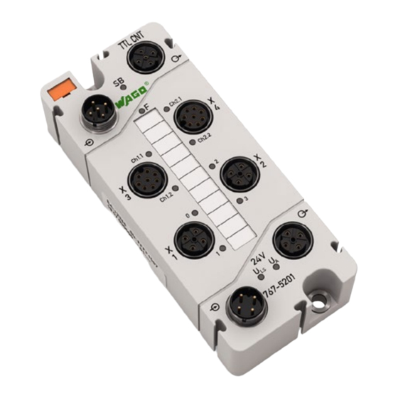
Pos : 18.4 /All e Seri en ( Allgemei ne Module)/Ü bers chriften für alle Serien/Gerätebesc hreibung/Ansc hlüs se - Übersc hrift 2 @ 4\mod_1240984262656_21.doc x @ 31961 @ 2 @ 1 Connectors Pos : 18.5 /Serie 767 (WAGO-SPEED WAY)/Ger ätebesc hrei bung/Ansc hl üss e/I/O-Module/Ansc hlüss e 767- 5201, - 5202 4xM12 - Bild @ 14\mod_1364224103822_21.doc x @ 115990 @ @ 1 Figure 1: Connectors Pos : 18.6 /Serie 767 (WAGO-SPEED WAY)/Ger ätebesc hrei bung/Ansc hl üss e/I/O-Module/Legende Anschl uss 767- xxxx S-BU S @ 5\mod_1248847875187_21.doc x @ 39167 @ @ 1... -
Page 19: Marking Possibilities And Fastening
Device Description 767-5201 TTL Incremental/SSI Encoder Pos : 18.11 /Serie 767 ( WAGO-SPEED WAY)/Gerätebeschr eibung/Befestigung/I/O-Module/Besc hriftung und Befestigung 767-xxxx_4xM 12_2x8-polig - Bild @ 15\mod_1371209899187_21.doc x @ 123160 @ 2 @ 1 Marking Possibilities and Fastening Figure 2: Marking possibilities and fastening Pos : 18.12 /Serie 767 ( WAGO-SPEED WAY)/Gerätebeschr eibung/Befestigung/I/O-Module/Legende z u Beschriftung und Befes tigung 767- xxxx @ 5\mod_1249475777546_21.doc x @ 40514 @ @ 1... -
Page 20: Display Elements
"Diagnostics" > "LED Signaling". Pos : 18.18 /Serie 767 ( WAGO-SPEED WAY)/Gerätebeschr eibung/Anz eigeel emente/I/O-M odul e/Legende zu Anz eigeel emente 767- xxxx, Pos. 18+19: Status U A und ULS @ 7\mod_1268053208570_21.doc x @ 51957 @ @ 1 Green Actuator supply is present. - Page 21 WAGO-SPEEDWAY 767 Device Description 767-5201 TTL Incremental/SSI Encoder Detailed information Detailed information can be found in section "Diagnostics" > "LED Signaling". Pos : 18.19 /D okumentati on allgemei n/Gli ederungsel emente/---Seitenwec hs el--- @ 3\mod_1221108045078_0.doc x @ 21810 @ @ 1 Manual Version 1.1.0...
-
Page 22: Labeling
Pos : 18.20.2 /Serie 767 ( WAGO-SPEEDWAY)/Gerätebeschr eibung/Bedr uc kung/I/O-M odul e/Bedruc kung 767-5201 - Bild @ 14\mod_1361893232521_21.doc x @ 113006 @ @ 1 Figure 4: Labeling Pos : 18.20.3 /Serie 767 ( WAGO-SPEEDWAY)/Gerätebeschr eibung/Bedr uc kung/I/O-M odul e/Legende zur Bedr uc kung 767- 5201 Geber + DIO @ 14\mod_1361956831253_21.doc x @ 113034 @ @ 1 Table 6: Legend for figure "Labeling"... -
Page 23: Figure 5: Label On The Module
Pos : 18.20.6 /Serie 767 ( WAGO-SPEEDWAY)/Gerätebeschr eibung/Bedr uc kung/I/O-M odul e/Bedruc kung sei tlich - Bild @ 5\mod_1248864035578_21.doc x @ 39357 @ @ 1 Figure 5: Label on the module Pos : 18.21 /Serie 767 ( WAGO-SPEED WAY)/Gerätebeschr eibung/Bedr uc kung/I/O-M odul e/Bedruc kung sei tlich - Legende @ 9\mod_1286969974465_21.doc x @ 65601 @ @ 1 Table 7: Description of manufacturing number... -
Page 24: Schematic Diagram
Schematic Diagram Pos : 18.24 /Serie 767 ( WAGO-SPEED WAY)/Gerätebeschr eibung/Sc hematis che Sc haltbilder/I/O-M odule/Ei nleitung zum sc hematisc hen Sc haltbil d 767-5201, -5202 D IO @ 14\mod_1364227515962_21.doc x @ 116011 @ @ 1 The following schematic diagram provides an overview of the power supply and principle of operation of the power supply connections, as well as the digital inputs and outputs of the modules (see also sections "Connecting the Supply... -
Page 25: Dimensions
Pos : 18.27 /Alle Serien (Allgemeine M odul e)/Übersc hriften für all e Seri en/Gerätebes chr eibung/Abmess ungen - Ü bersc hrift 2 @ 5\mod_1248869612468_21.doc x @ 39441 @ 2 @ 1 Dimensions Pos : 18.28 /Serie 767 ( WAGO-SPEED WAY)/Gerätebeschr eibung/Abmessungen/I/O-M odule/Abmessungen 767- xxxx_IO_4xM 12 - Bild @ 5\mod_1248873304828_21.doc x @ 39496 @ @ 1 Figure 7: Dimensions of the module in millimeters (exemplary) Pos : 18.29 /D okumentati on allgemei n/Gli ederungsel emente/---Seitenwec hs el--- @ 3\mod_1221108045078_0.doc x @ 21810 @ @ 1... -
Page 26: Technical Data
Pos : 18.33 /Serie 767 ( WAGO-SPEED WAY)/Gerätebeschr eibung/Tec hnisc he Daten/I/O-M odule/Gerätedaten_2_5201 @ 14\mod_1362058394406_21.doc x @ 113215 @ @ 1 Weight Approx. 270 g Pos : 18.34 /Serie 767 ( WAGO-SPEED WAY)/Gerätebeschr eibung/Tec hnisc he Daten/I/O-M odule/Sondermodul e/T ec hnisc he D aten 767-5201 @ 14\mod_1362059273804_21.doc x @ 113229 @ 33333333333333333 @ 1 3.7.2 Supply Table 9: Technical data −... -
Page 27: Incremental Encoder Interface
WAGO-SPEEDWAY 767 Device Description 767-5201 TTL Incremental/SSI Encoder 3.7.4 Incremental Encoder Interface Table 11: Technical data − Incremental encoder interface Number of inputs 2 (X3, X4) Connection type M12 connectors, A-coded, 8 poles, shielded Transmitter supply 5 V/24 V, max. 300 mA... -
Page 28: Input Characteristic
Device Description WAGO-SPEEDWAY 767 767-5201 TTL Incremental/SSI Encoder 3.7.7 Input Characteristic Table 14: Technical data − Input characteristic Input current at U = 0 V Typ. 0 mA at U = 5 V Typ. 2.0 mA at U = 15 V Typ. -
Page 29: Information For Actuator Selection
WAGO-SPEEDWAY 767 Device Description 767-5201 TTL Incremental/SSI Encoder 3.7.9 Information for Actuator Selection Table 16: Technical data − Actuator selection Delay time HW from 0 to 1 (0 – 90 %) < 10 µs (resistive load) from 1 to 0 (0 – 90 %) <... -
Page 30: Configurable Functions Of The Ssi Encoder Interfaces
Device Description WAGO-SPEEDWAY 767 767-5201 TTL Incremental/SSI Encoder 3.7.12 Configurable Functions of the SSI Encoder Interfaces Table 19: Technical data − Configurable functions of the SSI encoder interfaces Length data range 8 bits … 24 bits (default 13) Data length of the speed 0 bits …... -
Page 31: Diagnostics
: Supply status LED (green) LED indicators: Non-retentive Pos : 18.35 /Serie 767 ( WAGO-SPEED WAY)/Gerätebeschr eibung/Tec hnisc he Daten/I/O-M odule/Potentialtr ennung I/O-M odule @ 7\mod_1265957068843_21.doc x @ 50448 @ 3 @ 1 3.7.19 Isolation Table 26: Technical data − Isolation... -
Page 32: Approvals
Pos : 18.37.3.3 /D okumentati on allgemein/Gli ederungsel emente/------Leerzeil e------ @ 3\mod_1224662755687_0.doc x @ 24460 @ @ 1 Pos : 18.37.4 /Serie 767 ( WAGO-SPEEDWAY)/Gerätebeschr eibung/Zul ass ung en/Zul ass ung en I/O-Modul e 767- xxxx Ex, ohne Variantenangabe - Ei nlei tung @ 24\mod_1447686155055_21.doc x @ 195692 @ @ 1 The following Ex approvals are pending for 767-5201 module: Pos : 18.37.5 /Alle Serien (Allgemeine M odul e)/Z ulass ungen/Ex-Z ul ass ungen/TÜ... -
Page 33: Standards And Guidelines
Standards and Guidelines Pos : 18.39.2 /Serie 767 ( WAGO-SPEEDWAY)/Gerätebeschr eibung/Nor men und Richtlini en/N or men und Richtlinien I/O-Modul e 767- xxxx, ohne Variantenangabe - Ei nleitung @ 24\mod_1447686649865_21.doc x @ 195700 @ @ 1 The module 767-5201 meets the following standards and guidelines: Pos : 18.39.3 /Alle Serien (Allgemeine M odul e)/Nor men und Ric htlini en/EM V-Nor men - Standard/EG-EM V-Richtli nie 2004/108/EG @ 7\mod_1274262373820_21.doc x @ 56628 @ @ 1... -
Page 34: Mounting
Pos : 21.2 /Serie 767 (WAGO-SPEED WAY)/M ontier en/I/O-Modul e/M ontage_Hi nweis e 767- xxxx allgemei n_1 @ 5\mod_1249028727125_21.doc x @ 39643 @ 2 @ 1 Information on Mounting The following information shall always be observed: •... - Page 35 Mounting 767-5201 TTL Incremental/SSI Encoder Pos : 21.5 /Serie 767 (WAGO-SPEED WAY)/M ontier en/I/O-Modul e/Hi nweis : Montage_Ei nbaulag e_767- xxxx_I/O-M odule @ 24\mod_1448268126523_21.doc x @ 196008 @ @ 1 Any mounting position is possible. Ensure a safe mounting position! In explosion hazardous environments no increased mechanical loads must be present at the installation location.
-
Page 36: Tools And Accessories Required For Mounting
WAGO-SPEEDWAY 767 767-5201 TTL Incremental/SSI Encoder Pos : 21.7 /Serie 767 (WAGO-SPEED WAY)/M ontier en/I/O-Modul e/M ontage_Wer kzeug 767- xxxx allgemein_1 @ 5\mod_1249034240265_21.doc x @ 39783 @ 2 @ 1 Tools and Accessories Required for Mounting Depending on the mounting type, the following tools are required for installation: •... -
Page 37: Direct Mounting On Your System
Pos : 21.11 /Serie 767 ( WAGO-SPEED WAY)/Wichtige Erläuter ung en/Sic herheits hinweise/Hinweis/Hi nweis : 767- xxxx Distanz stüc k @ 8\mod_1279025151416_21.doc x @ 59810 @ @ 1 Direct Mounting We recommend using WAGO spacers for compact direct mounting. -
Page 38: Mounting On A Carrier Rail (Only With Wago Accessories)
Pos : 21.16 /Serie 767 ( WAGO-SPEED WAY)/Monti eren/I/O-M odule/Montage auf Tr agschi ene 767- xxxx_4xM 12 - Bil d @ 5\mod_1249284442703_21.doc x @ 39821 @ @ 1 Figure 9: Fastening to the carrier rail adapter Pos : 21.17 /D okumentati on allgemei n/Gli ederungsel emente/---Seitenwec hs el--- @ 3\mod_1221108045078_0.doc x @ 21810 @ @ 1... -
Page 39: Fastening The Module With Carrier Rail Adapter To A Carrier Rail
(item no.: 249-116 or 249-117) for stabilization is required. Pos : 21.19 /Serie 767 ( WAGO-SPEED WAY)/Monti eren/I/O-M odule/Montage_Befestigung auf Tragsc hi enenadapter 767- xxxx - Bil d @ 5\mod_1249030807718_21.doc x @ 39757 @ @ 1 Figure 10: Mounting the carrier rail adapter (exemplary) Pos : 21.20 /D okumentati on allgemei n/Gli ederungsel emente/---Seitenwec hs el--- @ 3\mod_1221108045078_0.doc x @ 21810 @ @ 1... -
Page 40: Mounting On A Profile Rail (Only With Wago Accessories)
WAGO-SPEEDWAY 767 767-5201 TTL Incremental/SSI Encoder Pos : 21.21 /Serie 767 ( WAGO-SPEED WAY)/Monti eren/I/O-M odule/Montage an einer Pr ofilsc hiene 767- xxxx allgemein @ 5\mod_1249031560359_21.doc x @ 39765 @ 23 @ 1 Mounting on a Profile Rail (only with WAGO Accessories) 4.5.1... -
Page 41: Fastening The Module With Profile Adapter To A Profile Rail
Mounting 767-5201 TTL Incremental/SSI Encoder Pos : 21.24 /Serie 767 ( WAGO-SPEED WAY)/Monti eren/I/O-M odule/Montage mi t Pr ofiladapter an einer Pr ofilsc hiene 767- xxxx allgemein @ 5\mod_1249032474562_21.doc x @ 39773 @ 3 @ 1 4.5.2 Fastening the Module with Profile Adapter to a Profile Rail To fasten the module to a profile rail of your system, two nuts are required with one screw each (length of screw threads must be compatible with your system). -
Page 42: Marking And Replacing The Marking Spaces
WAGO-SPEEDWAY 767 767-5201 TTL Incremental/SSI Encoder Pos : 21.26 /Serie 767 ( WAGO-SPEED WAY)/Monti eren/I/O-M odule/Montage_Besc hriftung austauschen 767- xxxx allgemein @ 5\mod_1249034032812_21.doc x @ 39780 @ 2 @ 1 Marking and Replacing the Marking Spaces The module marker card (10) and marking strip (12) are attached when delivered. -
Page 43: Mounting The Spacer In The Case Of Compact Arrangement
M4 screws via the mounting holes. Pos : 21.30 /Serie 767 ( WAGO-SPEED WAY)/Monti eren/I/O-M odule/Montage_Distanzstüc k T eil 1_767- xxxx_4xM 12 - Bil d @ 5\mod_1249284921328_21.doc x @ 39843 @ @ 1 Figure 13: Attaching a spacer to a module Pos : 21.31 /D okumentati on allgemei n/Gli ederungsel emente/---Seitenwec hs el--- @ 3\mod_1221108045078_0.doc x @ 21810 @ @ 1... -
Page 44: Figure 14: Attaching Another Module With A Spacer
The last 767 component is fastened without a spacer. Pos : 21.33 /Serie 767 ( WAGO-SPEED WAY)/Monti eren/I/O-M odule/Montage_Distanzstüc k T eil 2_767- xxxx_4xM 12 - Bil d @ 5\mod_1249284983031_21.doc x @ 39847 @ @ 1 Figure 14: Attaching another module with a spacer Pos : 22 /D okumentation allgemei n/Glieder ungs elemente/---Seitenwechs el--- @ 3\mod_1221108045078_0.doc x @ 21810 @ @ 1... -
Page 45: Connecting Data And Supply Cables
767-5201 TTL Incremental/SSI Encoder Pos : 23.1 /Serie 767 (WAGO-SPEED WAY)/Ans chl uss D aten- und Vers orgungs kabel/I/O-Modul e/01_Ansc hl uss der Daten- und Vers orgungs kabel - Übersc hrift 1 @ 8\mod_1278310189976_21.doc x @ 58919 @ 1 @ 1 Connecting Data and Supply Cables Pos : 23.2 /Serie 767 (WAGO-SPEED WAY)/Ans chl uss D aten- und Vers orgungs kabel/I/O-Modul e/02_Hinweis e - Ü... -
Page 46: Required Accessories
Pos : 23.9 /Serie 767 (WAGO-SPEED WAY)/Ans chl uss D aten- und Vers orgungs kabel/I/O-Modul e/Ans chl uss _Hinweise T eil 3.1 @ 8\mod_1278314911479_21.doc x @ 58959 @ @ 1 •... -
Page 47: Connecting The S-Bus Cables
Connecting Data and Supply Cables 767-5201 TTL Incremental/SSI Encoder Pos : 23.12 /Serie 767 ( WAGO-SPEED WAY)/Ansc hluss D aten- und Versorgungs kabel/I/O-M odule/Ansc hlus s_S-BU S allgemein @ 5\mod_1249287447062_21.doc x @ 39873 @ 2 @ 1 Connecting the S-BUS Cables The S-BUS is used for communication between a fieldbus coupler and the connected 767 Series components. -
Page 48: Figure 15: S-Bus Connected To A Fieldbus Coupler And Modules
Pos : 23.13 /Serie 767 ( WAGO-SPEED WAY)/Ansc hluss D aten- und Versorgungs kabel/I/O-M odule/Ansc hlus s_S-BU S_4xM 12 - Bil d @ 5\mod_1249301323125_21.doc x @ 40063 @ @ 1 Figure 15: S-BUS connected to a fieldbus coupler and modules Pos : 23.14 /D okumentati on allgemei n/Gli ederungsel emente/---Seitenwec hs el--- @ 3\mod_1221108045078_0.doc x @ 21810 @ @ 1... -
Page 49: Connecting The Supply Cable
0 V U Pos : 23.16 /Serie 767 ( WAGO-SPEED WAY)/Wichtige Erläuter ung en/Sic herheits hinweise/Ac htung/Ac htung: Höchs te Strombel astbar keit der Vers orgungs kontakte @ 8\mod_1278308653219_21.doc x @ 58916 @ @ 1 The highest current carrying capacity of the supply contacts is 4 A! -
Page 50: Figure 16: Supply Cable Connected To A Fieldbus Coupler And Modules
Pos : 23.19 /Serie 767 ( WAGO-SPEED WAY)/Ansc hluss D aten- und Versorgungs kabel/I/O-M odule/Ansc hlus s_Spannungs vers orgung _4xM 12 - Bild @ 5\mod_1249301804906_21.doc x @ 40067 @ @ 1 Figure 16: Supply cable connected to a fieldbus coupler and modules Pos : 23.20 /D okumentati on allgemei n/Gli ederungsel emente/---Seitenwec hs el--- @ 3\mod_1221108045078_0.doc x @ 21810 @ @ 1... -
Page 51: Connecting Interface Cables
Connecting Data and Supply Cables 767-5201 TTL Incremental/SSI Encoder Pos : 23.21 /Serie 767 ( WAGO-SPEED WAY)/Ansc hluss D aten- und Versorgungs kabel/I/O-M odule/Ansc hlus s_Geber-Sc hnittstellen 767-5201_4xM12 @ 14\mod_1362383051860_21.doc x @ 113500 @ 2 @ 1 Connecting Interface Cables The interface cables are used to connect external devices with a TTL Incremental/ SSI Encoder Interface. -
Page 52: Figure 17: Connectors Of Interfaces
Pos : 23.24 /Serie 767 ( WAGO-SPEED WAY)/Ansc hluss D aten- und Versorgungs kabel/I/O-M odule/Ansc hlüs se_4xM12_Geber-Sc hni ttstellen ( oben) - Bil d @ 14\mod_1364307267495_21.doc x @ 116070 @ @ 1 Figure 17: Connectors of interfaces Pos : 23.25 /D okumentati on allgemei n/Gli ederungsel emente/---Seitenwec hs el--- @ 3\mod_1221108045078_0.doc x @ 21810 @ @ 1... -
Page 53: Connecting Sensor/Actuator Cables
Connecting Data and Supply Cables 767-5201 TTL Incremental/SSI Encoder Pos : 23.26 /Serie 767 ( WAGO-SPEED WAY)/Ansc hluss D aten- und Versorgungs kabel/I/O-M odule/Ansc hlus s_Sens oren/Aktoren 767- 5201, - 5202_4xM12 @ 14\mod_1363785666328_21.doc x @ 115375 @ 2 @ 1 Connecting Sensor/Actuator Cables The sensor/actuator cable provides power to the connected sensors and actuators. -
Page 54: Figure 18: Connectors Of Sensors/Actuators
Pos : 23.29 /Serie 767 ( WAGO-SPEED WAY)/Ansc hluss D aten- und Versorgungs kabel/I/O-M odule/Ansc hlüs se_4xM12_Sensor en/Aktor en (unten) Geber-Sc hnittstellen - Bild @ 14\mod_1364307457846_21.doc x @ 116074 @ @ 1 Figure 18: Connectors of sensors/actuators Pos : 24 /D okumentation allgemei n/Glieder ungs elemente/---Seitenwechs el--- @ 3\mod_1221108045078_0.doc x @ 21810 @ @ 1... -
Page 55: Commissioning
Pos : 25 /All e Seri en (Allgemei ne Module)/Ü berschriften für alle Serien/Inbetri ebnehmen - Konfigurier en - Parametri eren - Bedienen/In Betri eb nehmen - Ü bersc hrift 1 @ 4\mod_1240901452750_21.doc x @ 31570 @ 1 @ 1 Commissioning Pos : 26 /Serie 767 ( WAGO-SPEED WAY)/Wic htige Erläuterungen/Sicherheits hinweis e/Achtung/Achtung: Offene Ansc hlüss e @ 8\mod_1278308159953_21.doc x @ 58910 @ @ 1 Exposed connections! If connections have not been closed with protective caps, liquid or dirt can penetrate the components of the 767 Series module and ruin it. -
Page 56: Parameterizing
Pos : 29 /All e Seri en (Allgemei ne Module)/Ü berschriften für alle Serien/Inbetri ebnehmen - Konfigurier en - Parametri eren - Bedienen/Parametrier en - Übersc hrift 1 @ 3\mod_1223554593484_21.doc x @ 23717 @ 1 @ 1 Parameterizing Pos : 30.1 /Serie 767 (WAGO-SPEED WAY)/Par ametrieren/I/O-M odule/Parametri erung 767- xxxx allgemei n @ 5\mod_1249376935062_21.doc x @ 40257 @ @ 1 All parameters listed here can be set using WAGOframe (or another FDT/DTM frame application) for the module. -
Page 57: Figure 19: Example Of An Open Dtm, Including Parameters
PC. Opens the DTM online help. Pos : 30.2 /Serie 767 (WAGO-SPEED WAY)/Par ametrieren/I/O-M odule/Parametri erung 767- xxxx allgemei n - Bild @ 5\mod_1249377954171_21.doc x @ 40275 @ @ 1 Figure 19: Example of an open DTM, including parameters Pos : 30.3 /Dokumentation allgemei n/Glieder ungs elemente/---Seitenwechs el--- @ 3\mod_1221108045078_0.doc x @ 21810 @ @ 1... -
Page 58: Electronic Type Label
WAGO-SPEEDWAY 767 767-5201 TTL Incremental/SSI Encoder Pos : 30.4 /Serie 767 (WAGO-SPEED WAY)/Par ametrieren/I/O-M odule/Parametri erung 767- xxxx Elektronisc hes T ypensc hild @ 5\mod_1249377784078_21.doc x @ 40260 @ 2 @ 1 Electronic Type Label Table 34: Information on the module... -
Page 59: Diagnostic Overview
Parameterizing 767-5201 TTL Incremental/SSI Encoder Pos : 30.6 /Serie 767 (WAGO-SPEED WAY)/Par ametrieren/I/O-M odule/Parametri erung 767- xxxx Di agnoseübersic ht_1 @ 14\mod_1360836957753_21.doc x @ 111870 @ 2 @ 1 Diagnostic Overview The currently pending diagnostics existing on the module are displayed here. In this view of the DTM, you can enable simulation of the diagnostics, as well as disable transmission of the diagnostics. -
Page 60: Table 36: Information About Existing Module Diagnostics
The switching threshold is typically 17 V. Pos : 30.10 /Serie 767 ( WAGO-SPEED WAY)/Parametrier en/I/O-Module/Parametrier ung Global e Di agnosen Kurzschl uss /Überlas t und U nterbr echung Fel dversorgung @ 8\mod_1278394655719_21.doc x @ 59061 @ @ 1 Short circuit/ overload... - Page 61 WAGO-SPEEDWAY 767 Parameterizing 767-5201 TTL Incremental/SSI Encoder Interruption of the S-BUS If there is an interruption of the S-BUS, the module is automatically put in STOP mode. The module outputs are disabled. Pos : 30.13 /D okumentati on allgemei n/Gli ederungsel emente/---Seitenwec hs el--- @ 3\mod_1221108045078_0.doc x @ 21810 @ @ 1 Manual Version 1.1.0...
-
Page 62: Counter Parameters
WAGO-SPEEDWAY 767 767-5201 TTL Incremental/SSI Encoder Pos : 30.14 /Serie 767 ( WAGO-SPEED WAY)/Parametrier en/I/O-Module/Parametrier ung 767-5201 Parameter der Z ählersc hni ttstellen @ 15\mod_1366351047330_21.doc x @ 117340 @ 233 @ 1 Counter Parameters Table 38: Overview of adjustable parameters for the counter... - Page 63 WAGO-SPEEDWAY 767 Parameterizing 767-5201 TTL Incremental/SSI Encoder Table 38: Overview of adjustable parameters for the counter Parameter Description: Lower limit The lower limit value can be defined here. If the counter reading lies outside of the defined range, a limiting value signal is generated – this is available as a status bit in the process image.
- Page 64 Parameterizing WAGO-SPEEDWAY 767 767-5201 TTL Incremental/SSI Encoder Table 38: Overview of adjustable parameters for the counter Parameter Description: Preset input Use this field to select the input that will be used as the trigger for the preset function. You can select the following settings:...
- Page 65 WAGO-SPEEDWAY 767 Parameterizing 767-5201 TTL Incremental/SSI Encoder Table 38: Overview of adjustable parameters for the counter Parameter Description: Latch value The current latch value is indicated in this field. This field is only displayed when you have selected "Incremental position encoder" as the encoder in the Counter function field.
- Page 66 Parameterizing WAGO-SPEEDWAY 767 767-5201 TTL Incremental/SSI Encoder Table 38: Overview of adjustable parameters for the counter Parameter Description: Multiple slope detect Set the type of encoder evaluation here: Single (1-fold) (positive edge)* Only detects rising edges of the signal at the A track of the square wave signal.
-
Page 67: Cam Parameters
WAGO-SPEEDWAY 767 Parameterizing 767-5201 TTL Incremental/SSI Encoder 7.3.1 Cam Parameters The cam function switches an output whenever the current counter reading appears in a selectable value range (minimum/maximum value). You can configure 4 cams per counter, whereby the cams are respectively assigned to one of the counter channels. -
Page 68: Ssi Encoder Parameters
Parameterizing WAGO-SPEEDWAY 767 767-5201 TTL Incremental/SSI Encoder 7.3.2 SSI Encoder Parameters If you have selected the SSI encoder as the counter function, you can parameterize as follows: Table 40: Overview of adjustable parameters for the SSI encoder Parameter Description: Data length Enter the number of the single-turn bits for the connected encoder here. - Page 69 WAGO-SPEEDWAY 767 Parameterizing 767-5201 TTL Incremental/SSI Encoder Table 40: Overview of adjustable parameters for the SSI encoder Parameter Description: Alarmbit evaluation Select whether the SSI encoder outputs an alarm bit. This alarm bit is evaluated by the module and forwarded as a diagnostic message: Checkbox unselected:* No alarm bit is output.
-
Page 70: Pulse Width Modulation Parameters
WAGO-SPEEDWAY 767 767-5201 TTL Incremental/SSI Encoder Pos : 30.16 /Serie 767 ( WAGO-SPEED WAY)/Parametrier en/I/O-Module/Parametrier ung 767-5201, -5202 Parameter der Puls weitenmodul ati on @ 14\mod_1363266955992_21.doc x @ 114520 @ 2 @ 1 Pulse Width Modulation Parameters You can configure two outputs as pulse width modulation (PWM) channels. -
Page 71: Input And Output Parameters
Parameterizing 767-5201 TTL Incremental/SSI Encoder Pos : 30.18 /Serie 767 ( WAGO-SPEED WAY)/Parametrier en/I/O-Module/Parametrier ung 767-5201, -5202 Parameter der digital en Ei n-/Ausgänge @ 14\mod_1362406091369_21.doc x @ 113584 @ 233 @ 1 Input and Output Parameters Selecting the Connection Mode Specify in which operating mode the connection should be operated. -
Page 72: Connection Mode "Digital Output
Parameterizing WAGO-SPEEDWAY 767 767-5201 TTL Incremental/SSI Encoder 7.5.1 Connection Mode "Digital Output" Table 43: Overview of adjustable parameters for the digital outputs Parameter Description: Function mode Mode display Designation Enter a designation for the connection. Max. 40 characters can be entered. - Page 73 WAGO-SPEEDWAY 767 Parameterizing 767-5201 TTL Incremental/SSI Encoder Table 43: Overview of adjustable parameters for the digital outputs Parameter Description: Actuator restart mode Set the restart behavior of an enabled output if the output has been disabled due to the "Overtemperature" diagnosis. You have the...
-
Page 74: Connection Mode "Digital Input
Parameterizing WAGO-SPEEDWAY 767 767-5201 TTL Incremental/SSI Encoder 7.5.2 Connection Mode "Digital Input" Table 44: Overview of adjustable parameters for the digital inputs Parameter Description: Function mode Mode display Designation Enter a designation for the connection. Max. 40 characters can be entered. -
Page 75: Global Settings
Parameterizing 767-5201 TTL Incremental/SSI Encoder Pos : 30.20 /Serie 767 ( WAGO-SPEED WAY)/Parametrier en/I/O-Module/Parametrier ung 767- xxxx Gl obal e Parameter @ 7\mod_1265881925390_21.doc x @ 50320 @ 2 @ 1 Global Settings Table 45: Overview of parameters for the entire module... -
Page 76: Field Supply Parameters
WAGO-SPEEDWAY 767 767-5201 TTL Incremental/SSI Encoder Pos : 30.22 /Serie 767 ( WAGO-SPEED WAY)/Parametrier en/I/O-Module/Parametrier ung 767-5201, -5202 Parameter der F eldvers orgung @ 14\mod_1363274097021_21.doc x @ 114524 @ 2 @ 1 Field Supply Parameters Table 46: Parameters for the field supply... -
Page 77: Automatic Storage Of System Parameters
"Parameter Setting via FDT/DTM" section. Pos : 30.25 /Serie 767 ( WAGO-SPEED WAY)/Parametrier en/I/O-Module/Parametrier ung 767- xxxx Aktualisier ung der Firmwar e @ 7\mod_1265881922171_21.doc x @ 50306 @ 2 @ 1 Updating the Firmware When updating the module firmware, the saved module parameters can be overwritten. -
Page 78: Process Image
You can enable or suppress the individual module diagnostics. For more information, see the Section "Diagnostics Overview". Pos : 34 /Serie 767 ( WAGO-SPEED WAY)/Wic htige Erläuterungen/Sicherheits hinweis e/Hi nweis /Hinweis: Prozess abbil d 767-5xxx @ 8\mod_1278504041994_21.doc x @ 59260 @ @ 1 Diagnostic Actuator short circuit/overload The "Actuator short circuit/overload"... -
Page 79: Input Data
Process Image 767-5201 TTL Incremental/SSI Encoder Pos : 36 /Serie 767 ( WAGO-SPEED WAY)/Proz ess abbild/I/O-Module/Proz ess abbil d 767-5201 Ei n- und Ausg angs daten @ 14\mod_1362468641549_21.doc x @ 113620 @ 22 @ 1 Input Data The process image for the process data sent to the fieldbus coupler from the module is 13 bytes long. - Page 80 Process Image WAGO-SPEEDWAY 767 767-5201 TTL Incremental/SSI Encoder Table 47: Process image of input data Byte 12 Digital inputs status Displays the status of the digital inputs : DI1 : DI2 : DI3 : DI4 : Always 0 : DI6...
-
Page 81: Output Data
WAGO-SPEEDWAY 767 Process Image 767-5201 TTL Incremental/SSI Encoder Output Data The process image for the process data sent from the fieldbus coupler to the module is 13 bytes long. If you parameterize synchronous diagnosis confirmation for the module, the process image increases to 15 bytes. - Page 82 Process Image WAGO-SPEEDWAY 767 767-5201 TTL Incremental/SSI Encoder Table 48: Process image of output data Byte 12 Digital outputs --------- -------- : DO1 : DO2 : DO3 : DO4 : Not used, always 0 Diagnostics confirmation: Byte 13 Byte 0...
-
Page 83: Counter Function
Counter Function 767-5201 TTL Incremental/SSI Encoder Pos : 38 /Serie 767 ( WAGO-SPEED WAY)/Sonderfunkti onen/I/O-Module/Z ähler/Z ählerfunktion 767- 5201_2 Z ähler, X1 ... X4 @ 14\mod_1362562639961_21.doc x @ 113780 @ 122333 @ 1 Counter Function The module also has available two mutually independent counter channels, which are functionally identical and can be parameterized independently from each other. -
Page 84: Operating Modes
Counter Function WAGO-SPEEDWAY 767 767-5201 TTL Incremental/SSI Encoder Operating Modes There are three operating modes available for the counter: • Event counter This counts the pulses detected on the counter input. If a gate has been defined, then the counter function can also be selected and unselected. -
Page 85: Controlling And Monitoring The Counter Via The Process Data
WAGO-SPEEDWAY 767 Counter Function 767-5201 TTL Incremental/SSI Encoder Controlling and Monitoring the Counter via the Process Data The status and control bytes that can be used to monitor and control the counter will be subsequently explained: 9.2.1 Status Bytes The counter reading is output via the status bytes in the process image, which are... -
Page 86: Table 50: Status Byte S1
Counter Function WAGO-SPEEDWAY 767 767-5201 TTL Incremental/SSI Encoder Table 50: Status byte S1 Status byte S1 Bit 15 Bit 14 Bit 13 Bit 12 Bit 11 Bit 10 Bit 9 Bit 8 Select value for process Set ACK Selected register for set value... -
Page 87: Control Bytes
WAGO-SPEEDWAY 767 Counter Function 767-5201 TTL Incremental/SSI Encoder 9.2.2 Control Bytes The control bytes enable configuration of the counter using process data. The following functions are available: Table 51: Control byte C0 Control byte C0 Bit 7 Bit 6 Bit 5... -
Page 88: Table 52: Control Byte C1
Counter Function WAGO-SPEEDWAY 767 767-5201 TTL Incremental/SSI Encoder Table 52: Control byte C1 Control byte C1 Bit 15 Bit 14 Bit 13 Bit 12 Bit 11 Bit 10 Bit 9 Bit 8 Select value for process Select register for set value... -
Page 89: Example For Controlling Two Counters Via Process Data
WAGO-SPEEDWAY 767 Counter Function 767-5201 TTL Incremental/SSI Encoder 9.2.3 Example for Controlling Two Counters via Process Data Example 1: Preparation for the Latch Signal Table 53: Example: Preparation for the latch signal Binary [bit 15…0] Hexadeci Description: 0xxx xxxx xxxx xxx1... -
Page 90: Diagnostics
Information regarding remedies of certain causes is also provided. Pos : 42.2 /Serie 767 (WAGO-SPEED WAY)/Wic htige Erläuterungen/Sicherheits hinweis e/Hi nweis /Hinweis: 767- 4xxx/- 5xxx Betriebs meldungen Deakti vierbar e Diag nos en @ 7\mod_1265892089421_21.doc x @ 50332 @ @ 1 Disabling specific diagnostics Use the diagnostic overview (section "Parameterizing"... - Page 91 S-BUS cable for damages. Pos : 42.5 /Serie 767 (WAGO-SPEED WAY)/Di agnose/I/O-Modul e/Betriebs mel dungen 767- 5xxx D IO Allgemein ( Pos. 15, T eil 2) @ 7\mod_1268637618295_21.doc x @ 52466 @ @ 1 Green, flashing,...
-
Page 92: Table 56: Operational Messages 2
WAGO-SPEEDWAY 767 767-5201 TTL Incremental/SSI Encoder Pos : 42.7 /Serie 767 (WAGO-SPEED WAY)/Di agnose/I/O-Modul e/Betriebs mel dungen 767- 5201 F, I/O (Pos. 16 + 17) @ 14\mod_1362570003226_21.doc x @ 113788 @ @ 1 Indicator Functions The indicator functions for inputs Ch1.1 … Ch2.2 (LED 17) depend on the operating mode selected for the interface (incremental encoder interface or SSI encoder interface). -
Page 93: Table 57: Operational Messages 3
LED Color/status Cause Remedy/information Pos : 42.10 /Serie 767 ( WAGO-SPEED WAY)/Diag nos e/I/O-M odule/Betri ebs meldungen 767- xxxx ULS und U A ( Pos . 18 + 19) @ 8\mod_1278577022948_21.doc x @ 59316 @ @ 1 Green Actuator supply U present. -
Page 94: Service
Disconnect the power supply from those devices on which you have mounted the module. Pos : 48 /Serie 767 ( WAGO-SPEED WAY)/Wic htige Erläuterungen/Sicherheits hinweis e/Vorsic ht/Vorsicht: H eiße Ansc hlussbuc hs en @ 8\mod_1278308217203_21.doc x @ 58913 @ @ 1 Hot connection sockets! Even when taking into account derating, high surface temperatures on the metallic connection sockets and on the enclosure can arise during operation. -
Page 95: Removing The Module From Your System
WAGO-SPEEDWAY 767 Service 767-5201 TTL Incremental/SSI Encoder Pos : 51 /Serie 767 ( WAGO-SPEED WAY)/Ser vic e/I/O-M odule/Ser vic e 767- xxxx allgemein 2.2 @ 8\mod_1278649957222_21.doc x @ 59430 @ 3 @ 1 11.2.2 Removing the Module from Your System... -
Page 96: Removing The Module From The Profile Adapter
WAGO-SPEEDWAY 767 767-5201 TTL Incremental/SSI Encoder Pos : 55 /Serie 767 ( WAGO-SPEED WAY)/Ser vic e/I/O-M odule/Ser vic e 767- xxxx allgemein 4 @ 5\mod_1249471383765_21.doc x @ 40467 @ 332 @ 1 11.2.4 Removing the Module from the Profile Adapter... -
Page 97: Appendix
Pos : 57 /All e Seri en (Allgemei ne Module)/Ü berschriften für alle Serien/Anhang - Z ubehör Anhang - Ü bers chrift 1 @ 4\mod_1239874070437_21.doc x @ 30560 @ 1 @ 1 Appendix Pos : 58 /Serie 767 ( WAGO-SPEED WAY)/Anhang/I/O-M odule/Anhang 767-5201 Di agnos einfor mation @ 14\mod_1362727965793_21.doc x @ 114000 @ 2 @ 1 12.1... -
Page 98: List Of Figures
List of Figures WAGO-SPEEDWAY 767 767-5201 TTL Incremental/SSI Encoder Pos : 60 /D okumentation allgemei n/Verz eic hniss e/Abbil dungs verz eic hnis - Übersc hrift oG und Verz eichnis @ 3\mod_1219222916765_21.doc x @ 21080 @ @ 1 List of Figures Figure 1: Connectors ..................... -
Page 99: List Of Tables
WAGO-SPEEDWAY 767 List of Tables 767-5201 TTL Incremental/SSI Encoder Pos : 62 /D okumentation allgemei n/Verz eic hniss e/Tabell enverz eichnis - Übersc hrift oG und Verz eichnis @ 3\mod_1219222958703_21.doc x @ 21084 @ @ 1 List of Tables Table 1: Number Notation ..................9 Table 2: Font Conventions .................. - Page 100 List of Tables WAGO-SPEEDWAY 767 767-5201 TTL Incremental/SSI Encoder Table 46: Parameters for the field supply ............. 76 Table 47: Process image of input data ..............79 Table 48: Process image of output data ..............81 Table 49: Status byte S0 ..................85 Table 50: Status byte S1 ..................
- Page 101 WAGO-SPEEDWAY 767 767-5201 TTL Incremental/SSI Encoder Pos : 64 /D okumentation allgemei n/Einband/Einband H andbuc h - Leers eite für durc h 2 teilbar e Seitenzahl (Standar ddr uc k) @ 3\mod_1219230851078_0.doc x @ 21123 @ @ 1 Manual Version 1.1.0...
- Page 102 Pos : 65 /D okumentation allgemei n/Einband/Einband H andbuc h - R üc kseite 2015 @ 9\mod_1285229376516_21.doc x @ 64944 @ @ 1 WAGO Kontakttechnik GmbH & Co. KG Postfach 2880 • D-32385 Minden Hansastraße 27 • D-32423 Minden Phone: 05 71/8 87 –...
Need help?
Do you have a question about the 767-5201 and is the answer not in the manual?
Questions and answers