Table of Contents
Advertisement
Quick Links
WAGO-SPEEDWAY 767
Pos : 2 /D okumentati on allgemein/Ei nband/Ei nband H andbuch - Fronts eite 2015 - mit Doc Variabl en (Standar d) @ 9\mod_1285229289866_0.doc x @ 64941 @ @ 1
Manual
767-5801/000-800
8DIO 24V DC 0.5A IF (8xM8)
Digital Input/Output Module 24 V DC / 0.5 A
Version 1.1.0
Pos : 3 /Alle Serien (Allgemeine M odul e)/Hinweise z ur Dokumentation/Impres sum für Standardhandbüc her - allg. Angaben, Ansc hriften, Tel efonnummer n und E-Mail-Adres sen @ 3\mod_1219151118203_21.doc x @ 21060 @ @ 1
Advertisement
Chapters
Table of Contents

Related Manuals for WAGO WAGO-SPEEDWAY 767


Summary of Contents for WAGO WAGO-SPEEDWAY 767
- Page 1 WAGO-SPEEDWAY 767 Pos : 2 /D okumentati on allgemein/Ei nband/Ei nband H andbuch - Fronts eite 2015 - mit Doc Variabl en (Standar d) @ 9\mod_1285229289866_0.doc x @ 64941 @ @ 1 Manual 767-5801/000-800 8DIO 24V DC 0.5A IF (8xM8) Digital Input/Output Module 24 V DC / 0.5 A...
- Page 2 WAGO-SPEEDWAY 767 767-5801/000-800 8DIO 24V DC 0.5A IF (8xM8) © 2016 by WAGO Kontakttechnik GmbH & Co. KG All rights reserved. WAGO Kontakttechnik GmbH & Co. KG Hansastraße 27 D-32423 Minden Phone: +49 (0) 571/8 87 – 0 Fax: +49 (0) 571/8 87 – 1 69 E-Mail: info@wago.com...
-
Page 3: Table Of Contents
Standards and Guidelines ................ 32 Mounting ..................... 33 Information on Mounting ................ 33 Tools and Accessories Required for Mounting ........35 Direct Mounting on Your System ............36 Mounting on a Carrier Rail (only with WAGO Accessories) ....37 Manual Version 1.1.0... - Page 4 Fastening the Carrier Rail Adapter to the Module ......37 4.4.2 Fastening the Module with Carrier Rail Adapter to a Carrier Rail ..................38 Mounting on a Profile Rail (only with WAGO Accessories) ....39 4.5.1 Fastening the Profile Adapter to the Module ........39 4.5.2 Fastening the Module with Profile Adapter to a Profile Rail .....
-
Page 5: Table Of Contents
WAGO-SPEEDWAY 767 Table of Contents 767-5801/000-800 8DIO 24V DC 0.5A IF (8xM8) 9.2.2 Status Byte ..................83 9.2.3 Example of Controlling Two Counters via the Process Data ..... 84 Diagnostics ....................85 10.1 LED Signaling ..................85 Service ......................88 11.1... -
Page 6: Notes About This Documentation
Pos : 9 /Seri e 767 ( WAGO- SPEED WAY) /Wic htige Erl äuter ung en/Sic her hei tshi nweis e/Warnung/Warnung: R eleas e N otes beac hten @ 8\mod_1278912368761_21.doc x @ 59530 @ @ 1... -
Page 7: Symbols
WAGO-SPEEDWAY 767 Notes about this Documentation 767-5801/000-800 8DIO 24V DC 0.5A IF (8xM8) Pos : 13.3 /All e Seri en ( Allgemei ne Module)/Ü bers chriften für alle Serien/Hinweis e z ur Dokumentation/Symbol e - Ü bersc hrift 2 @ 13\mod_1351068042408_21.doc x @ 105270 @ 2 @ 1 Symbols Pos : 13.4.1 /All e Serien ( Allgemei ne Module)/Wic htige Erläuterungen/Sicherheits- und sons tige Hinweis e/Gefahr/Gefahr: _War nung vor Personenschäden allgemei n_ - Erl äuter ung @ 13\mod_1343309450020_21.doc x @ 101029 @ @ 1... - Page 8 Notes about this Documentation WAGO-SPEEDWAY 767 767-5801/000-800 8DIO 24V DC 0.5A IF (8xM8) Additional Information: Refers to additional information which is not an integral part of this documentation (e.g., the Internet). Pos : 13.5 /Dokumentation allgemei n/Glieder ungs elemente/---Seitenwechs el--- @ 3\mod_1221108045078_0.doc x @ 21810 @ @ 1 Manual Version 1.1.0...
-
Page 9: Number Notation
Font Conventions Table 2: Font Conventions Font Type Indicates italic Names of paths and data files are marked in italic-type. e.g.: C:\Program Files\WAGO Software Menu Menu items are marked in bold letters. e.g.: Save > A greater-than sign between two names means the selection of a menu item from a menu. -
Page 10: Important Notes
Thus, the existence of such rights cannot be excluded. Pos : 16.4 /Serie 767 (WAGO-SPEED WAY)/Wic htige Erläuterungen/I/O-M odul/Pers onalqualifi kation 767- xxxx @ 5\mod_1248175871265_21.doc x @ 38705 @ 3 @ 1 2.1.2... -
Page 11: Use In Compliance With Underlying Provisions
Pos : 16.8 /Serie 767 (WAGO-SPEED WAY)/Wic htige Erläuterungen/I/O-M odul/Bes timmungsgemäß e Verwendung 767-D Os 1_1 Hi nweis _R üc kwir kungsfr ei @ 11\mod_1317278760144_21.doc x @ 79992 @ @ 1 The digital outputs of the module are interference-free to eliminate any impact by the internal potential groups. -
Page 12: Technical Condition Of Specified Devices
Please send your request for modified and new hardware or software configurations directly to WAGO Kontakttechnik GmbH & Co. KG. Pos : 16.13 /D okumentati on allgemei n/Gli ederungsel emente/---Seitenwec hs el--- @ 3\mod_1221108045078_0.doc x @ 21810 @ @ 1 Manual Version 1.1.0... -
Page 13: Safety Advice (Precautions)
Series component has been in operation, allow it to cool off before moving it. Pos : 16.17 /Serie 767 ( WAGO-SPEED WAY)/Wichtige Erläuter ung en/Sic herheits hinweise/Ac htung/Ac htung: Höchs te Strombel astbar keit der Vers orgungs kontakte @ 8\mod_1278308653219_21.doc x @ 58916 @ @ 1... -
Page 14: Safety Equipment
Observe the marking on the front and rear side of the module. Pos : 16.22 /Serie 767 ( WAGO-SPEED WAY)/Wichtige Erläuter ung en/I/O-Modul /Sic her hei tsei nrichtungen 767- xxxx @ 7\mod_1268142379773_21.doc x @ 52055 @ 2 @ 1 Safety Equipment All 767 Series products are designed to meet the requirements of IP67. -
Page 15: Notes On Operation
Important Notes 767-5801/000-800 8DIO 24V DC 0.5A IF (8xM8) Pos : 16.24 /Serie 767 ( WAGO-SPEED WAY)/Wichtige Erläuter ung en/I/O-Modul /Hinweise z um Betri eb 767- xxxx, Teil 1 @ 7\mod_1266921815843_21.doc x @ 51219 @ 2 @ 1 Notes on Operation... -
Page 16: Device Description
Pos : 18.1 /All e Seri en ( Allgemei ne Module)/Ü bers chriften für alle Serien/Gerätebesc hreibungGer ätebesc hrei bung - Ü berschrift 1 @ 3\mod_1233756084656_21.doc x @ 27096 @ 1 @ 1 Device Description Pos : 18.2 /Serie 767 (WAGO-SPEED WAY)/Ger ätebesc hrei bung/I/O-Module/Gerätebes chr eibung 767- 58xx @ 7\mod_1268051953922_21.doc x @ 51943 @ @ 1 The module 767-5801/000-800 is a hybrid module, which can be operated in five ways: •... -
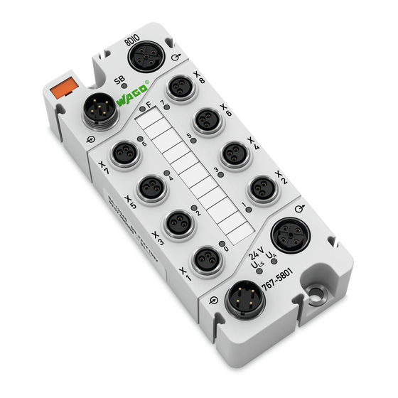
Page 17: Connectors
Pos : 18.8 /Serie 767 (WAGO-SPEED WAY)/Ger ätebesc hrei bung/Ansc hl üss e/I/O-Module/Legende Anschl uss 767- xxxx Vers orgung, nic ht 4803 und 4804 @ 5\mod_1248847875765_21.doc x @ 39171 @ @ 1 Supply output... -
Page 18: Marking Possibilities And Fastening
WAGO-SPEEDWAY 767 767-5801/000-800 8DIO 24V DC 0.5A IF (8xM8) Pos : 18.10 /Serie 767 ( WAGO-SPEED WAY)/Gerätebeschr eibung/Befestigung/I/O-Module/Besc hriftung und Befestigung 767-xxxx_8xM 8 - Bild @ 5\mod_1248845069421_21.doc x @ 39114 @ 2 @ 1 Bes chriftungsmöglichkeiten Marking Possibilities and Fastening Figure 2: Marking possibilities and fastening (exemplary) Pos : 18.11 /Serie 767 ( WAGO-SPEED WAY)/Gerätebeschr eibung/Befestigung/I/O-Module/Legende z u Beschriftung und Befes tigung 767- xxxx @ 5\mod_1249475777546_21.doc x @ 40514 @ @ 1... -
Page 19: Display Elements
Yellow/red Status signal inputs/ outputs Pos : 18.17 /Serie 767 ( WAGO-SPEED WAY)/Gerätebeschr eibung/Anz eigeel emente/I/O-M odul e/Legende zu Anz eigeel emente 767- xxxx, Pos. 18+19: Status U A und ULS @ 7\mod_1268053208570_21.doc x @ 51957 @ @ 1 Green Actuator supply is present. -
Page 20: Labeling
Figure 4: Labeling (example) Pos : 18.19.3 /Serie 767 ( WAGO-SPEEDWAY)/Gerätebeschr eibung/Bedr uc kung/I/O-M odul e/Legende zur Bedr uc kung 767- 5xxx D IO, auß er 5803 @ 7\mod_1268045599057_21.doc x @ 51932 @ @ 1 Table 6: Legend for figure "Labeling"... -
Page 21: Figure 5: Label On The Module
Pos : 18.19.6 /Serie 767 ( WAGO-SPEEDWAY)/Gerätebeschr eibung/Bedr uc kung/I/O-M odul e/Bedruc kung sei tlich - Bild @ 5\mod_1248864035578_21.doc x @ 39357 @ @ 1 Figure 5: Label on the module Pos : 18.20 /Serie 767 ( WAGO-SPEED WAY)/Gerätebeschr eibung/Bedr uc kung/I/O-M odul e/Bedruc kung sei tlich - Legende @ 9\mod_1286969974465_21.doc x @ 65601 @ @ 1 Table 7: Description of manufacturing number... -
Page 22: Schematic Diagram
Schematic Diagram Pos : 18.23 /Serie 767 ( WAGO-SPEED WAY)/Gerätebeschr eibung/Sc hematis che Sc haltbilder/I/O-M odule/Ei nleitung zum sc hematisc hen Sc haltbil d 767-5xxx DIO @ 10\mod_1306757989112_21.doc x @ 73325 @ @ 1 The following schematic diagram provides an overview of the power supply and principle of operation of the power supply connections, as well as the digital inputs and outputs of the modules (see also chapters "Connecting the Supply... -
Page 23: Dimensions
Pos : 18.26 /Alle Serien (Allgemeine M odul e)/Übersc hriften für all e Seri en/Gerätebes chr eibung Abmess ung en - Übersc hrift 2 @ 5\mod_1248869612468_21.doc x @ 39441 @ 2 @ 1 Dimensions Pos : 18.27 /Serie 767 ( WAGO-SPEED WAY)/Gerätebeschr eibung/Abmessungen/I/O-M odule/Abmessungen 767- xxxx_IO_8xM 8 - Bild @ 5\mod_1248872498546_21.doc x @ 39493 @ @ 1 Figure 7: Dimensions of the module in millimeters (exemplary) Pos : 18.28 /D okumentati on allgemei n/Gli ederungsel emente/---Seitenwec hs el--- @ 3\mod_1221108045078_0.doc x @ 21810 @ @ 1... -
Page 24: Technical Data
Pos : 18.32 /Serie 767 ( WAGO-SPEED WAY)/Gerätebeschr eibung/Tec hnisc he Daten/I/O-M odule/Gerätedaten_2_5801 @ 9\mod_1286971546341_21.doc x @ 65620 @ @ 1 Weight Approx. 260 g Pos : 18.33 /Serie 767 ( WAGO-SPEED WAY)/Gerätebeschr eibung/Tec hnisc he Daten/I/O-M odule/Sondermodul e/T ec hnisc he D aten 767-5801/000-800 @ 11\mod_1325587707519_21.doc x @ 84730 @ 3333333333333 @ 1 3.7.2 Supply Table 9: Technical data –... -
Page 25: Inputs
WAGO-SPEEDWAY 767 Device Description 767-5801/000-800 8DIO 24V DC 0.5A IF (8xM8) 3.7.4 Inputs Table 11: Technical data – Inputs Number of inputs Connection type M8 connectors, 3 poles Wire connection 2- or 3-wire Input filter Hardware: ≤ 110 μs Software: parametrizable Input characteristic Type 1, acc. -
Page 26: Input Characteristic
Device Description WAGO-SPEEDWAY 767 767-5801/000-800 8DIO 24V DC 0.5A IF (8xM8) 3.7.5 Input Characteristic Table 12: Technical data – Input Characteristic Input voltage Typical input current 0 V DC 0.6 mA 11 V 2.6 mA 24 V 3.0 mA 30 V 3.2 mA... -
Page 27: Information On Actuator Selection
WAGO-SPEEDWAY 767 Device Description 767-5801/000-800 8DIO 24V DC 0.5A IF (8xM8) 3.7.7 Information on actuator selection Table 14: Technical data – Information on actuator selection Delay time hardware from 0 to 1 (0 – 90 %) 90 µs (resistive load) from 1 to 0 (0 –... -
Page 28: Configurable Functions
Device Description WAGO-SPEEDWAY 767 767-5801/000-800 8DIO 24V DC 0.5A IF (8xM8) 3.7.10 Configurable Functions Table 17: Technical data – Configurable Functions Operating mode (per module) Output module Input module Input and output module Input and output module + 1 counter... -
Page 29: Configurable Functions For Counters
WAGO-SPEEDWAY 767 Device Description 767-5801/000-800 8DIO 24V DC 0.5A IF (8xM8) 3.7.11 Configurable functions for counters Table 18: Technical data – Configurable functions for counters Counter mode - Event counter - Gate time measurement - Pulse duration counter Gate time basis... -
Page 30: Diagnostics
: Supply status LED (green) Indicators Non-retentive Pos : 18.34 /Serie 767 ( WAGO-SPEED WAY)/Gerätebeschr eibung/Tec hnisc he Daten/I/O-M odule/Potentialtr ennung I/O-M odule @ 7\mod_1265957068843_21.doc x @ 50448 @ 3 @ 1 3.7.15 Isolation Table 22: Technical data − Isolation... -
Page 31: Approvals
Pos : 18.36.3.3 /D okumentati on allgemein/Gli ederungsel emente/------Leerzeil e------ @ 3\mod_1224662755687_0.doc x @ 24460 @ @ 1 Pos : 18.36.4 /Serie 767 ( WAGO-SPEEDWAY)/Gerätebeschr eibung/Zul ass ung en/Zul ass ung en I/O-Modul e 767- xxxx Ex, ohne Variantenangabe - Ei nlei tung @ 24\mod_1447686155055_21.doc x @ 195692 @ @ 1 The following Ex approvals are pending for 767-5801/000-800 module: Pos : 18.36.5 /Alle Serien (Allgemeine M odul e)/Z ulass ungen/Ex-Z ul ass ungen/TÜ... -
Page 32: Standards And Guidelines
Standards and Guidelines Pos : 18.38.2 /Serie 767 ( WAGO-SPEEDWAY)/Gerätebeschr eibung/Nor men und Richtlini en/N or men und Richtlinien I/O-Modul e 767- xxxx, ohne Variantenangabe - Ei nleitung @ 24\mod_1447686649865_21.doc x @ 195700 @ @ 1 The module 767-5801/000-800 meets the following standards and guidelines: Pos : 18.38.3 /Alle Serien (Allgemeine M odul e)/Nor men und Ric htlini en/EM V-Nor men - Standard/EG-EM V-Richtli nie 2004/108/EG @ 7\mod_1274262373820_21.doc x @ 56628 @ @ 1... -
Page 33: Mounting
Pos : 21.2 /Serie 767 (WAGO-SPEED WAY)/M ontier en/I/O-Modul e/M ontage_Hi nweis e 767- xxxx allgemei n_1 @ 5\mod_1249028727125_21.doc x @ 39643 @ 2 @ 1 Information on Mounting The following information shall always be observed: •... - Page 34 WAGO-SPEEDWAY 767 767-5801/000-800 8DIO 24V DC 0.5A IF (8xM8) Pos : 21.5 /Serie 767 (WAGO-SPEED WAY)/M ontier en/I/O-Modul e/Hi nweis : Montage_Ei nbaulag e_767- xxxx_I/O-M odule @ 24\mod_1448268126523_21.doc x @ 196008 @ @ 1 Any mounting position is possible. Ensure a safe mounting position! In explosion hazardous environments no increased mechanical loads must be present at the installation location.
-
Page 35: Tools And Accessories Required For Mounting
Mounting 767-5801/000-800 8DIO 24V DC 0.5A IF (8xM8) Pos : 21.7 /Serie 767 (WAGO-SPEED WAY)/M ontier en/I/O-Modul e/M ontage_Wer kzeug 767- xxxx allgemein_1 @ 5\mod_1249034240265_21.doc x @ 39783 @ 2 @ 1 Tools and Accessories Required for Mounting Depending on the mounting type, the following tools are required for installation: •... -
Page 36: Direct Mounting On Your System
Pos : 21.11 /Serie 767 ( WAGO-SPEED WAY)/Wichtige Erläuter ung en/Sic herheits hinweise/Hinweis/Hi nweis : 767- xxxx Distanz stüc k @ 8\mod_1279025151416_21.doc x @ 59810 @ @ 1 Direct Mounting We recommend using WAGO spacers for compact direct mounting. -
Page 37: Mounting On A Carrier Rail (Only With Wago Accessories)
Mounting 767-5801/000-800 8DIO 24V DC 0.5A IF (8xM8) Pos : 21.15 /Serie 767 ( WAGO-SPEED WAY)/Monti eren/I/O-M odule/Montage auf Tr agschi ene 767- xxxx allgemei n @ 5\mod_1249030348312_21.doc x @ 39746 @ 23 @ 1 Mounting on a Carrier Rail (only with WAGO Accessories) 4.4.1... -
Page 38: Fastening The Module With Carrier Rail Adapter To A Carrier Rail
(item no.: 249-116 or 249-117) for stabilization is required. Pos : 21.19 /Serie 767 ( WAGO-SPEED WAY)/Monti eren/I/O-M odule/Montage_Befestigung auf Tragsc hi enenadapter 767- xxxx - Bil d @ 5\mod_1249030807718_21.doc x @ 39757 @ @ 1 Figure 10: Mounting the carrier rail adapter (exemplary) Pos : 21.20 /D okumentati on allgemei n/Gli ederungsel emente/---Seitenwec hs el--- @ 3\mod_1221108045078_0.doc x @ 21810 @ @ 1... -
Page 39: Mounting On A Profile Rail (Only With Wago Accessories)
Pos : 21.22 /Serie 767 ( WAGO-SPEED WAY)/Monti eren/I/O-M odule/Montage an einer Pr ofilsc hiene 767- xxxx_8xM8 - Bil d @ 5\mod_1249032233640_21.doc x @ 39769 @ @ 1 Figure 11: Fastening to the profile adapter Pos : 21.23 /D okumentati on allgemei n/Gli ederungsel emente/---Seitenwec hs el--- @ 3\mod_1221108045078_0.doc x @ 21810 @ @ 1... -
Page 40: Fastening The Module With Profile Adapter To A Profile Rail
WAGO-SPEEDWAY 767 767-5801/000-800 8DIO 24V DC 0.5A IF (8xM8) Pos : 21.24 /Serie 767 ( WAGO-SPEED WAY)/Monti eren/I/O-M odule/Montage mi t Pr ofiladapter an einer Pr ofilsc hiene 767- xxxx allgemein @ 5\mod_1249032474562_21.doc x @ 39773 @ 3 @ 1 4.5.2... -
Page 41: Marking And Replacing The Marking Spaces
New module marker cards can be obtained through WAGO. Pos : 21.27 /Serie 767 ( WAGO-SPEED WAY)/Monti eren/I/O-M odule/Montage_Besc hriftung austauschen 767- xxxx_8xM8 - Bil d @ 5\mod_1249280838031_21.doc x @ 39793 @ @ 1 Figure 12: Replacing the marking spaces Pos : 21.28 /D okumentati on allgemei n/Gli ederungsel emente/---Seitenwec hs el--- @ 3\mod_1221108045078_0.doc x @ 21810 @ @ 1... -
Page 42: Mounting The Spacer In The Case Of Compact Arrangement
767-5801/000-800 8DIO 24V DC 0.5A IF (8xM8) Pos : 21.29 /Serie 767 ( WAGO-SPEED WAY)/Monti eren/I/O-M odule/Montage_Distanzstüc k T eil 1_767- xxxx allgemei n @ 5\mod_1249281269203_21.doc x @ 39797 @ 2 @ 1 Mounting the Spacer in the Case of Compact... -
Page 43: Figure 14: Attaching Another Module With A Spacer
The last 767 component is fastened without a spacer. Pos : 21.33 /Serie 767 ( WAGO-SPEED WAY)/Monti eren/I/O-M odule/Montage_Distanzstüc k T eil 2_767- xxxx_8xM 8 - Bild @ 5\mod_1249281783109_21.doc x @ 39809 @ @ 1 Figure 14: Attaching another module with a spacer Pos : 22 /D okumentation allgemei n/Glieder ungs elemente/---Seitenwechs el--- @ 3\mod_1221108045078_0.doc x @ 21810 @ @ 1... -
Page 44: Connecting Data And Supply Cables
767-5801/000-800 8DIO 24V DC 0.5A IF (8xM8) Pos : 23.1 /Serie 767 (WAGO-SPEED WAY)/Ans chl uss D aten- und Vers orgungs kabel/I/O-Modul e/01_Ansc hl uss der Daten- und Vers orgungs kabel - Übersc hrift 1 @ 8\mod_1278310189976_21.doc x @ 58919 @ 1 @ 1 Connecting Data and Supply Cables Pos : 23.2 /Serie 767 (WAGO-SPEED WAY)/Ans chl uss D aten- und Vers orgungs kabel/I/O-Modul e/02_Hinweis e - Ü... -
Page 45: Required Accessories
Pos : 23.9 /Serie 767 (WAGO-SPEED WAY)/Ans chl uss D aten- und Vers orgungs kabel/I/O-Modul e/Ans chl uss _Hinweise T eil 3.1 @ 8\mod_1278314911479_21.doc x @ 58959 @ @ 1 •... -
Page 46: Connecting The S-Bus Cables
WAGO-SPEEDWAY 767 767-5801/000-800 8DIO 24V DC 0.5A IF (8xM8) Pos : 23.12 /Serie 767 ( WAGO-SPEED WAY)/Ansc hluss D aten- und Versorgungs kabel/I/O-M odule/Ansc hlus s_S-BU S allgemein @ 5\mod_1249287447062_21.doc x @ 39873 @ 2 @ 1 Connecting the S-BUS Cables The S-BUS is used for communication between a fieldbus coupler and the connected 767 Series components. -
Page 47: Figure 15: S-Bus Connected To A Fieldbus Coupler And Modules
Pos : 23.13 /Serie 767 ( WAGO-SPEED WAY)/Ansc hluss D aten- und Versorgungs kabel/I/O-M odule/Ansc hlus s_S-BU S_8xM 8 - Bild @ 5\mod_1249291591812_21.doc x @ 39902 @ @ 1 Figure 15: S-BUS connected to a fieldbus coupler and modules Pos : 23.14 /D okumentati on allgemei n/Gli ederungsel emente/---Seitenwec hs el--- @ 3\mod_1221108045078_0.doc x @ 21810 @ @ 1... -
Page 48: Connecting The Supply Cable
0 V U Pos : 23.16 /Serie 767 ( WAGO-SPEED WAY)/Wichtige Erläuter ung en/Sic herheits hinweise/Ac htung/Ac htung: Höchs te Strombel astbar keit der Vers orgungs kontakte @ 8\mod_1278308653219_21.doc x @ 58916 @ @ 1 The highest current carrying capacity of the supply contacts is 4 A! -
Page 49: Figure 16: Supply Cable Connected To A Fieldbus Coupler And Modules
Pos : 23.20 /Serie 767 ( WAGO-SPEED WAY)/Ansc hluss D aten- und Versorgungs kabel/I/O-M odule/Ansc hlus s_Spannungs vers orgung _8xM 8 - Bild @ 5\mod_1249292056906_21.doc x @ 39910 @ @ 1 Figure 16: Supply cable connected to a fieldbus coupler and modules Pos : 23.21 /D okumentati on allgemei n/Gli ederungsel emente/---Seitenwec hs el--- @ 3\mod_1221108045078_0.doc x @ 21810 @ @ 1... -
Page 50: Connect Sensor/Actuator Cable
767-5801/000-800 8DIO 24V DC 0.5A IF (8xM8) Pos : 23.22 /Serie 767 ( WAGO-SPEED WAY)/Ansc hluss D aten- und Versorgungs kabel/I/O-M odule/Ansc hlus s_Sens oren/Aktoren 767- 58xx_8xM 8_2 Z ähler @ 7\mod_1268056131666_21.doc x @ 51987 @ 2 @ 1 Connect Sensor/Actuator Cable The sensor/actuator cable provides power to the connected sensors and actuators. -
Page 51: Figure 17: Connectors (Exemplary)
767-5801/000-800 8DIO 24V DC 0.5A IF (8xM8) Pos : 23.25 /Serie 767 ( WAGO-SPEED WAY)/Ansc hluss D aten- und Versorgungs kabel/I/O-M odule/Ansc hlus s_Sens oren/Aktoren 767- 5xxx allgemein @ 7\mod_1268056627185_21.doc x @ 51991 @ @ 1 To connect the sensors/actuators to the digital inputs/outputs (X1 – X4) proceed... -
Page 52: Commissioning
Pos : 25 /All e Seri en (Allgemei ne Module)/Ü berschriften für alle Serien/Inbetri ebnehmen - Konfigurier en - Parametri eren - Bedienen/In Betri eb nehmen - Ü bersc hrift 1 @ 4\mod_1240901452750_21.doc x @ 31570 @ 1 @ 1 Commissioning Pos : 26 /Serie 767 ( WAGO-SPEED WAY)/Wic htige Erläuterungen/Sicherheits hinweis e/Achtung/Achtung: Offene Ansc hlüss e @ 8\mod_1278308159953_21.doc x @ 58910 @ @ 1 Exposed connections! If connections have not been closed with protective caps, liquid or dirt can penetrate the components of the 767 Series module and ruin it. -
Page 53: Parameterizing
Pos : 29 /All e Seri en (Allgemei ne Module)/Ü berschriften für alle Serien/Inbetri ebnehmen - Konfigurier en - Parametri eren - Bedienen/Parametrier en - Übersc hrift 1 @ 3\mod_1223554593484_21.doc x @ 23717 @ 1 @ 1 Parameterizing Pos : 30.1 /Serie 767 (WAGO-SPEED WAY)/Par ametrieren/I/O-M odule/Parametri erung 767- xxxx allgemei n @ 5\mod_1249376935062_21.doc x @ 40257 @ @ 1 All parameters listed here can be set using WAGOframe (or another FDT/DTM frame application) for the module. -
Page 54: Figure 18: Example Of An Open Dtm, Including Parameters
PC. Opens the DTM online help. Pos : 30.2 /Serie 767 (WAGO-SPEED WAY)/Par ametrieren/I/O-M odule/Parametri erung 767- xxxx allgemei n - Bild @ 5\mod_1249377954171_21.doc x @ 40275 @ @ 1 Figure 18: Example of an open DTM, including parameters Pos : 30.3 /Dokumentation allgemei n/Glieder ungs elemente/---Seitenwechs el--- @ 3\mod_1221108045078_0.doc x @ 21810 @ @ 1... -
Page 55: Electronic Type Label
Parameterizing 767-5801/000-800 8DIO 24V DC 0.5A IF (8xM8) Pos : 30.4 /Serie 767 (WAGO-SPEED WAY)/Par ametrieren/I/O-M odule/Parametri erung 767- xxxx Elektronisc hes T ypensc hild @ 5\mod_1249377784078_21.doc x @ 40260 @ 2 @ 1 Electronic Type Label Table 28: Information on the module... -
Page 56: Diagnostic Overview
WAGO-SPEEDWAY 767 767-5801/000-800 8DIO 24V DC 0.5A IF (8xM8) Pos : 30.6 /Serie 767 (WAGO-SPEED WAY)/Par ametrieren/I/O-M odule/Parametri erung 767- xxxx Di agnoseübersic ht_1 @ 14\mod_1360836957753_21.doc x @ 111870 @ 2 @ 1 Diagnostic Overview The currently pending diagnostics existing on the module are displayed here. In this view of the DTM, you can enable simulation of the diagnostics, as well as disable transmission of the diagnostics. -
Page 57: Table 30: Information About Existing Module Diagnostics
The module F-LED illuminates. Pos : 30.10 /Serie 767 ( WAGO-SPEED WAY)/Parametrier en/I/O-Module/Parametrier ung Global e Di agnosen Kurzschl uss /Überlas t und U nterbr echung Fel dversorgung @ 8\mod_1278394655719_21.doc x @ 59061 @ @ 1... -
Page 58: Input And Output Parameters
767-5801/000-800 8DIO 24V DC 0.5A IF (8xM8) Pos : 30.14 /Serie 767 ( WAGO-SPEED WAY)/Parametrier en/I/O-Module/Parametrier ung 767-58xx Parameter der Ein-/Ausgänge s owi e die unterschi edlic hen Betriebs arten @ 7\mod_1268126776552_21.doc x @ 52019 @ 33333 @ 1 7.2.1... -
Page 59: Do Module" Mode
WAGO-SPEEDWAY 767 Parameterizing 767-5801/000-800 8DIO 24V DC 0.5A IF (8xM8) 7.2.2 "DO Module" Mode Table 33: Overview of adjustable parameters for the digital outputs Parameter Description Function mode Mode display Designation Electronic marking field (max. 40 characters). Output value The output state is indicated in this field. - Page 60 Parameterizing WAGO-SPEEDWAY 767 767-5801/000-800 8DIO 24V DC 0.5A IF (8xM8) Table 33: Overview of adjustable parameters for the digital outputs Parameter Description Actuator restart mode Set the restart behavior of an enabled output if the output has been disabled due to the "Overtemperature" diagnosis. You have the following...
-
Page 61: Di Module" Mode
WAGO-SPEEDWAY 767 Parameterizing 767-5801/000-800 8DIO 24V DC 0.5A IF (8xM8) 7.2.3 "DI Module" Mode Table 34: Overview of adjustable parameters for the digital inputs Parameter Description Function mode Mode display Designation Electronic marking field (max. 40 characters) Input value The input state is indicated in this box. -
Page 62: Dio Module With Counter" Mode
Parameterizing WAGO-SPEEDWAY 767 767-5801/000-800 8DIO 24V DC 0.5A IF (8xM8) 7.2.5 "DIO Module with Counter" Mode Table 35: Overview of adjustable counter parameters for the DIO Module Parameter Description Counter value This field indicates the counter status Counter mode The counter can be used in 3 modes: Event counter: The counter counts the detected pulse on the counter input. - Page 63 WAGO-SPEEDWAY 767 Parameterizing 767-5801/000-800 8DIO 24V DC 0.5A IF (8xM8) Table 35: Overview of adjustable counter parameters for the DIO Module Parameter Description Start/limit value Enter a value (0 - 65535), which is used as the start value or as a reference to control the switching output.
-
Page 64: Global Settings
), the corresponding diagnostic is displayed here. Low voltage U Pos : 30.17 /Serie 767 ( WAGO-SPEED WAY)/Parametrier en/I/O-Module/Parametrier ung 767-38xx, 5xxx, 6401, 7401 Param. der F el dvers orgung @ 5\mod_1249379780656_21.doc x @ 40285 @ 2 @ 1 Parameters of Field Supply... -
Page 65: Automatic Storage Of System Parameters
"Parameter Setting via FDT/DTM" section. Pos : 30.20 /Serie 767 ( WAGO-SPEED WAY)/Parametrier en/I/O-Module/Parametrier ung 767- xxxx Aktualisier ung der Firmwar e @ 7\mod_1265881922171_21.doc x @ 50306 @ 2 @ 1 Updating the Firmware When updating the module firmware, the saved module parameters can be overwritten. -
Page 66: Process Image
Process Image Pos : 33 /Serie 767 ( WAGO-SPEED WAY)/Proz ess abbild/I/O-Module/Proz ess abbil d 767-580x Proz ess abbild betri ebs artabhängig @ 8\mod_1278503684836_21.doc x @ 59227 @ @ 1 The size of the process image depends on the configured operating mode: •... - Page 67 You can enable or suppress the individual module diagnostics. For more information, see the Section "Diagnostics Overview". Pos : 35 /Serie 767 ( WAGO-SPEED WAY)/Wic htige Erläuterungen/Sicherheits hinweis e/Hi nweis /Hinweis: Prozess abbil d 767-5xxx @ 8\mod_1278504041994_21.doc x @ 59260 @ @ 1 Diagnostic Actuator short circuit/overload The "Actuator short circuit/overload"...
-
Page 68: Do Mode
Process Image WAGO-SPEEDWAY 767 767-5801/000-800 8DIO 24V DC 0.5A IF (8xM8) Pos : 37 /Serie 767 ( WAGO-SPEED WAY)/Proz ess abbild/I/O-Module/Proz ess abbil d 767-580x Ein- und Ausgangsdaten @ 7\mod_1268117983077_21.doc x @ 52010 @ 233233233233233 @ 1 DO Mode 8.1.1... -
Page 69: Output Data
WAGO-SPEEDWAY 767 Process Image 767-5801/000-800 8DIO 24V DC 0.5A IF (8xM8) 8.1.2 Output Data The image for the process data, which are transmitted by the fieldbus coupler to the I/O module, has a size of 1 byte. If you configure a synchronous diagnostic confirmation of the I/O module, the process image has a size of 3 bytes. -
Page 70: Di Mode
Process Image WAGO-SPEEDWAY 767 767-5801/000-800 8DIO 24V DC 0.5A IF (8xM8) DI Mode 8.2.1 Input Data The image for the process data, which are transmitted from the I/O module to the fieldbus coupler, has a size of 1 byte. If you configure synchronous diagnostic data for the I/O module, the process image has a size of 3 bytes. -
Page 71: Output Data
WAGO-SPEEDWAY 767 Process Image 767-5801/000-800 8DIO 24V DC 0.5A IF (8xM8) 8.2.2 Output Data The image for the process data, which are transmitted by the fieldbus coupler to the I/O module, has a size of 0 byte. If you configure a synchronous diagnostic confirmation of the I/O module, the process image has a size of 2 bytes. -
Page 72: Dio Mode
Process Image WAGO-SPEEDWAY 767 767-5801/000-800 8DIO 24V DC 0.5A IF (8xM8) DIO Mode 8.3.1 Input Data The image for the process data, which are transmitted from the I/O module to the fieldbus coupler, has a size of 1 byte. If you configure synchronous diagnostic data for the I/O module, the process image has a size of 3 bytes. -
Page 73: Output Data
WAGO-SPEEDWAY 767 Process Image 767-5801/000-800 8DIO 24V DC 0.5A IF (8xM8) 8.3.2 Output Data The image for the process data, which are transmitted by the fieldbus coupler to the I/O module, has a size of 1 byte. If you configure a synchronous diagnostic confirmation of the I/O module, the process image has a size of 3 bytes. -
Page 74: Dio Mode + 1 Counter
Process Image WAGO-SPEEDWAY 767 767-5801/000-800 8DIO 24V DC 0.5A IF (8xM8) DIO Mode + 1 Counter 8.4.1 Input Data The image for the process data, which are transmitted from the I/O module to the fieldbus coupler, has a size of 4 bytes. If you configure synchronous diagnostic data for the I/O module, the process image has a size of 6 bytes. -
Page 75: Output Data
WAGO-SPEEDWAY 767 Process Image 767-5801/000-800 8DIO 24V DC 0.5A IF (8xM8) Byte 5 Diagnostic message -------- -------- : Short circuit/overload field supply | always 0 : Undervoltage U : Undervoltage U Not assigned: always 0 8.4.2 Output Data The image for the process data, which are transmitted by the fieldbus coupler to the I/O module, has a size of 4 bytes. -
Page 76: Table 45: Dio + 1 Counter, Output Data In The Process Image
Process Image WAGO-SPEEDWAY 767 767-5801/000-800 8DIO 24V DC 0.5A IF (8xM8) Table 45: DIO + 1 counter, output data in the process image Byte 0 Digital outputs (process data) ------------------- ------------------- : Output value = True Byte 1 Counter controller... -
Page 77: Dio Mode + 2 Counters
WAGO-SPEEDWAY 767 Process Image 767-5801/000-800 8DIO 24V DC 0.5A IF (8xM8) DIO Mode + 2 Counters 8.5.1 Input Data The image for the process data, which is transmitted from the I/O module to the fieldbus coupler, has a size of 6 bytes. If you configure synchronous diagnostic data for the I/O module, the process image has a size of 8 bytes. -
Page 78: Output Data
Process Image WAGO-SPEEDWAY 767 767-5801/000-800 8DIO 24V DC 0.5A IF (8xM8) Byte 6 Diagnostic message : Overtemperature on channel 1 : Overtemperature on channel 2 : Overtemperature on channel 3 : Overtemperature on channel 4 : Overtemperature on channel 5... -
Page 79: Table 47: Dio + 2 Counters, Output Data In The Process Image
WAGO-SPEEDWAY 767 Process Image 767-5801/000-800 8DIO 24V DC 0.5A IF (8xM8) Table 47: DIO + 2 counters, output data in the process image Byte 0 Digital outputs (process data) ------------------- ------------------- : Output value = True Byte 1 Counter controller... -
Page 80: Counter Function
WAGO-SPEEDWAY 767 767-5801/000-800 8DIO 24V DC 0.5A IF (8xM8) Pos : 39 /Serie 767 ( WAGO-SPEED WAY)/Sonderfunkti onen/I/O-Module/Z ähler/Z ählerfunktion 767- 58xx_2 Z ähler, X1 ... X8 @ 11\mod_1317797260418_21.doc x @ 80610 @ 122333 @ 1 Counter function The module also makes available two counters independent of one another, which can be controlled both via the physical connections X1 …... -
Page 81: Control Of The Counter Via Inputs And Outputs
In order to control the counter functions via the inputs and outputs of the module, switch these on via DTMs using WAGOframe or another FDT/DTM framework application. You can find the necessary DTMs at wago.com. This configuration is also possible with some fieldbus systems (e.g. PROFIBUS > GSD). -
Page 82: Controlling And Monitoring Of The Counter Via The Process Data
Counter function WAGO-SPEEDWAY 767 767-5801/000-800 8DIO 24V DC 0.5A IF (8xM8) Controlling and Monitoring of the Counter via the Process Data The control byte and status byte used for counter controlling and monitoring are listed below: 9.2.1 Control Byte The control byte allows the configuration of the counter via the process data:... -
Page 83: Status Byte
WAGO-SPEEDWAY 767 Counter function 767-5801/000-800 8DIO 24V DC 0.5A IF (8xM8) 9.2.2 Status Byte The counter status is output via the status byte in the process image, which is defined as follows: Table 50: Status byte Status byte counter 1, 2... -
Page 84: Example Of Controlling Two Counters Via The Process Data
Counter function WAGO-SPEEDWAY 767 767-5801/000-800 8DIO 24V DC 0.5A IF (8xM8) 9.2.3 Example of Controlling Two Counters via the Process Data Prerequisite: For the module in DTM, you have set the operating mode "DIO module + 2 counters." For control of the counter via the output data, the parameter "Simulation"... -
Page 85: Diagnostics
Information regarding remedies of certain causes is also provided. Pos : 43.2 /Serie 767 (WAGO-SPEED WAY)/Wic htige Erläuterungen/Sicherheits hinweis e/Hi nweis /Hinweis: 767- 4xxx/- 5xxx Betriebs meldungen Deakti vierbar e Diag nos en @ 7\mod_1265892089421_21.doc x @ 50332 @ @ 1 Disabling specific diagnostics Use the diagnostic overview (section "Parameterizing"... - Page 86 S-BUS cable for damages. Pos : 43.5 /Serie 767 (WAGO-SPEED WAY)/Di agnose/I/O-Modul e/Betriebs mel dungen 767- 5xxx D IO Allgemein ( Pos. 15, T eil 2) @ 7\mod_1268637618295_21.doc x @ 52466 @ @ 1 Green, flashing,...
-
Page 87: Table 53: Operating Messages 2
Pos : 43.8 /Serie 767 (WAGO-SPEED WAY)/Di agnose/I/O-Modul e/Betriebs mel dungen 767- xxxx U LS und UA (Pos. 18 + 19) @ 8\mod_1278577022948_21.doc x @ 59316 @ @ 1 Green Actuator supply U present. -
Page 88: Service
Disconnect the power supply from those devices on which you have mounted the module. Pos : 49 /Serie 767 ( WAGO-SPEED WAY)/Wic htige Erläuterungen/Sicherheits hinweis e/Vorsic ht/Vorsicht: H eiße Ansc hlussbuc hs en @ 8\mod_1278308217203_21.doc x @ 58913 @ @ 1 Hot connection sockets! Even when taking into account derating, high surface temperatures on the metallic connection sockets and on the enclosure can arise during operation. -
Page 89: Removing The Module From Your System
Service 767-5801/000-800 8DIO 24V DC 0.5A IF (8xM8) Pos : 52 /Serie 767 ( WAGO-SPEED WAY)/Ser vic e/I/O-M odule/Ser vic e 767- xxxx allgemein 2.2 @ 8\mod_1278649957222_21.doc x @ 59430 @ 3 @ 1 11.2.2 Removing the Module from Your System... -
Page 90: Removing The Module From The Profile Adapter
WAGO-SPEEDWAY 767 767-5801/000-800 8DIO 24V DC 0.5A IF (8xM8) Pos : 56 /Serie 767 ( WAGO-SPEED WAY)/Ser vic e/I/O-M odule/Ser vic e 767- xxxx allgemein 4 @ 5\mod_1249471383765_21.doc x @ 40467 @ 332 @ 1 11.2.4 Removing the Module from the Profile Adapter... -
Page 91: Use Of The Interference-Free Module In Safety Applications
767-5801/000-800 8DIO 24V DC 0.5A IF (8xM8) Pos : 58.1 /Serie 767 (WAGO-SPEED WAY)/Eins atz in sicherheitsg erichteten Anwendung en/767- xxxx_Ei nsatz des rüc kwirkungsfrei en Moduls in Sic herheits anwendung en_1 @ 11\mod_1317280241272_21.doc x @ 79997 @ 1 @ 1... -
Page 92: General Measures And Conditions For The Power Supply Solution Of The Module
767-5801/000-800 8DIO 24V DC 0.5A IF (8xM8) Pos : 58.4 /Serie 767 (WAGO-SPEED WAY)/Eins atz in sicherheitsg erichteten Anwendung en/767- xxxx_Allgemeine M aßnahmen und Auflag en für das Versorgungs konz ept des Moduls_3 @ 11\mod_1317280455233_21.doc x @ 80003 @ 2 @ 1 12.2... - Page 93 U and U can each be protected using a safety fuse according to EN 60127-2 or electronic fuse, e.g. WAGO 787-861. Safety fuses according to EN 60127-2 must meet the following technical requirements: •...
-
Page 94: Measures And Conditions For Shielded Power Supply Of The Module
767-5801/000-800 8DIO 24V DC 0.5A IF (8xM8) Pos : 58.6 /Serie 767 (WAGO-SPEED WAY)/Eins atz in sicherheitsg erichteten Anwendung en/767- xxxx_M aß nahmen und Aufl agen für die gesc hirmte Spannungs versorgung des Moduls _4 @ 11\mod_1317280498953_21.doc x @ 80015 @ 2 @ 1 12.3... -
Page 95: Measures And Conditions For Unshielded Power Supply Of The Module
767-5801/000-800 8DIO 24V DC 0.5A IF (8xM8) Pos : 58.8 /Serie 767 (WAGO-SPEED WAY)/Eins atz in sicherheitsg erichteten Anwendung en/767- xxxx_M aß nahmen und Aufl agen für die ungesc hir mte Spannungs versorgung des Moduls_5 @ 11\mod_1317280618487_21.doc x @ 80006 @ 2 @ 1 12.4... -
Page 96: Connection Of The Module To Safety Switching Devices
767-5801/000-800 8DIO 24V DC 0.5A IF (8xM8) Pos : 58.10 /Serie 767 ( WAGO-SPEED WAY)/Ei ns atz i n sic herheitsgeric hteten Anwendungen/767- xxxx_Anschl uss des M oduls an Sicherheitss chaltger äte_6 @ 11\mod_1317280654504_21.doc x @ 80009 @ 23 @ 1 12.5... -
Page 97: Examples Of Connection
Use of the Interference-Free Module in Safety Applications 767-5801/000-800 8DIO 24V DC 0.5A IF (8xM8) Pos : 60 /Serie 767 ( WAGO-SPEED WAY)/Eins atz in sicherheitsg erichteten Anwendung en/767- xxxx_Ansc hlus sbeispi el_M 8_7 @ 11\mod_1317280693802_21.doc x @ 80012 @ 3 @ 1 12.5.2... -
Page 98: Appendix
Pos : 62 /All e Seri en (Allgemei ne Module)/Ü berschriften für alle Serien/Anhang - Z ubehör Anhang - Ü bers chrift 1 @ 4\mod_1239874070437_21.doc x @ 30560 @ 1 @ 1 Appendix Pos : 63 /Serie 767 ( WAGO-SPEED WAY)/Anhang/I/O-M odule/Anhang 767-58xx Di agnos einfor mation @ 7\mod_1268133111596_21.doc x @ 52031 @ 2 @ 1 13.1... -
Page 99: List Of Figures
WAGO-SPEEDWAY 767 List of Figures 767-5801/000-800 8DIO 24V DC 0.5A IF (8xM8) Pos : 65 /D okumentation allgemei n/Verz eic hniss e/Abbil dungs verz eic hnis - Übersc hrift oG und Verz eichnis @ 3\mod_1219222916765_21.doc x @ 21080 @ @ 1 List of Figures Figure 1: Connectors ..................... -
Page 100: List Of Tables
List of Tables WAGO-SPEEDWAY 767 767-5801/000-800 8DIO 24V DC 0.5A IF (8xM8) Pos : 67 /D okumentation allgemei n/Verz eic hniss e/Tabell enverz eichnis - Übersc hrift oG und Verz eichnis @ 3\mod_1219222958703_21.doc x @ 21084 @ @ 1 List of Tables Table 1: Number Notation .................. - Page 101 WAGO-SPEEDWAY 767 List of Tables 767-5801/000-800 8DIO 24V DC 0.5A IF (8xM8) Table 49: Control byte ................... 82 Table 50: Status byte ..................... 83 Table 51: Example of controlling two counters via control byte ......84 Table 52: Operating messages 1 ................85 Table 53: Operating messages 2 ................
- Page 102 Pos : 69 /D okumentation allgemei n/Einband/Einband H andbuc h - Leers eite für durc h 2 teilbar e Seitenzahl (Standar ddr uc k) @ 3\mod_1219230851078_0.doc x @ 21123 @ @ 1 Pos : 70 /D okumentation allgemei n/Einband/Einband H andbuc h - R üc kseite 2015 @ 9\mod_1285229376516_21.doc x @ 64944 @ @ 1 WAGO Kontakttechnik GmbH & Co. KG Postfach 2880 •...
Need help?
Do you have a question about the WAGO-SPEEDWAY 767 and is the answer not in the manual?
Questions and answers