Sign In
Upload
Manuals
Brands
WAGO Manuals
Control Unit
767-1201
WAGO 767-1201 Manuals
Manuals and User Guides for WAGO 767-1201. We have
1
WAGO 767-1201 manual available for free PDF download: Manual
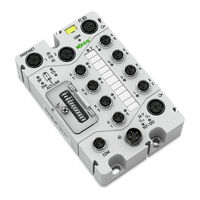
WAGO 767-1201 Manual (220 pages)
PROFINET IO Fielbus Coupler For WAGO-SPEEDWAY 767
Brand:
WAGO
| Category:
Control Unit
| Size: 9.88 MB
Table of Contents
Table of Contents
5
Table of Contents
3
Table of Contents
7
1 Notes about this Documentation
8
Validity of These Operating Instructions
8
Copyright
8
Symbols
9
Number Notation
11
Font Conventions
11
Table 1: Number Notation
11
Table 2: Font Conventions
11
2 Important Notes
12
Legal Bases
12
Subject to Changes
12
Personnel Qualification
12
Use in Compliance with Underlying Provisions
13
Technical Condition of Specified Devices
13
Safety Advice (Precautions)
14
Safety Equipment
15
Notes on Operation
16
Special Use Conditions for ETHERNET Devices
16
3 System Description
18
4 Device Description
21
Connectors
23
Figure 1: Connectors
23
Table 3: Legend for Figure "Connectors
23
Marking Possibilities and Fastening
24
Figure 2: Marking Possibilities and Fastening
24
Table 4: Legend for Figure "Marking Possibilities and Fastening
24
Display Elements
25
Figure 3: Display Elements
25
Table 5: Legend for Figure "Display Elements
25
Operating Elements
27
Figure 4: DIP Switch. All Switches Are Set on "Off" at Delivery
27
Table 6: Default Settings of DIP Switch
27
Table 7: Explanation of DIP Switch
28
Labeling
29
Figure 5: Labeling on the Back Side
29
Table 8: Legend for Figure "Labeling on the Back Side
29
Figure 6: Label on Fieldbus Coupler
30
Table 9: Description of Manufacturing Number
30
Schematic Diagram
31
Figure 7: Schematic Diagram
31
Dimensions
32
Figure 8: Dimensions of Fieldbus Coupler in MM
32
Technical Data
33
Device Data
33
System Data
33
Table 10: Technical Data - Device Data
33
Table 11: Technical Data - System Data
33
Supply
34
Communication
34
Inputs
34
Table 12: Technical Data - Supply
34
Table 13: Technical Data - Communication
34
Table 14: Technical Data - Inputs
34
Configurable Functions
35
Diagnostics
35
Process Image
35
Indicators
35
Table 15: Technical Data - Configurable Functions
35
Table 16: Technical Data - Diagnostics
35
Table 17: Technical Data - Process Image
35
Table 18: Technical Data - Indicators
35
Service Interface COM
36
Isolation
36
Table 19: Technical Data - Service Interface
36
Table 20: Technical Data − Isolation
36
Approvals
37
Standards and Guidelines
38
5 Mounting
39
Information on Mounting
39
Tools and Accessories Required for Mounting
41
Direct Mounting on Your System
42
Figure 9: Mounting the Fieldbus Coupler on the Grounded System
42
Mounting on a Carrier Rail (Only with WAGO Accessories)
43
Fastening the Carrier Rail Adapter to the Fieldbus Coupler
43
Figure 10: Fastening the Fieldbus Coupler to the Carrier Rail Adapter
43
Fastening the Fieldbus Coupler with Carrier Rail Adapter to a Carrier Rail
44
Figure 11: Mounting the Carrier Rail Adapter
44
Mounting on a Profile Rail (Only with WAGO Accessories)
45
Fastening the Profile Adapter to the Fieldbus Coupler
45
Figure 12: Fastening the Fieldbus Coupler to the Profile Adapter
45
Fastening the Fieldbus Coupler with Profile Adapter to a Profile Rail
46
Replacing the Marker Card and Strip
47
Figure 13: Replacing the Marker Card and Strip
47
Mounting the Spacer in the Case of Compact Arrangement
48
Figure 14: Attaching a Spacer
48
Figure 15: Attaching Another 767 Component to the Fieldbus Coupler
49
6 Connecting Data and Supply Cables
50
Notes
50
Required Accessories
51
Connecting the Fieldbus Cable
52
Table 21: ETHERNET Connection Assignments
52
Connecting a Fieldbus Coupler to an ETHERNET Network
53
Connecting Several Fieldbus Couplers Inside an ETHERNET Network
53
Figure 16: the Fieldbus Coupler Is Connected to the ETHERNET Network
53
Figure 17: Example Setup of a Mixed Topology with Four Fieldbus Couplers
54
Figure 18: Example Setup of a Mixed Topology with Four Fieldbus Couplers
55
Connecting the S-BUS Cable
56
Table 22: S-BUS Connection Assignment
56
Figure 19: S-BUS Is Connected to One Fieldbus Coupler and Two I/O Modules
57
Connecting the Supply Cable
58
Table 23: Supply Connection Assignment
58
Figure 20: Supply Cable Connected with Fieldbus Coupler and I/O Modules
59
Connecting the Sensor Cables
60
Table 24: Connection Assignment of Digital Inputs
60
Figure 21: Digital Inputs
61
Connecting the USB Cable
62
Table 25: USB Connection Assignment
62
Figure 22: USB Interface
63
7 Commissioning
64
Setting the PROFINET Station Name
65
Table 26: Default Settings of DIP Switch
65
Figure 23: DIP Switch Set for Instance 52
66
Switching on the Fieldbus Coupler
67
The Web-Based Management (WBM)
68
Figure 24: "Authentication Required" Dialog Box
68
Information" View
69
Figure 25: "Information" View
69
Table 27: Parameter Description of the Page "Information
69
ETHERNET" View
70
Table 28: Parameter Description of the Page "ETHERNET
70
TCP/IP" View
71
Port" View
71
Table 29: Parameter Description of the Page "TCP/IP
71
Table 30: Parameter Description of the Page "Port
71
SNMP" View
72
Table 31: Parameter Description of the Page "SNMP
72
SNMP V3" View
73
Table 32: Parameter Description of the Page "SNMP V3
73
Clock" View
74
Users" View
74
Table 33: Parameter Description of the Page "Clock
74
Administration" View
75
8 Configuration
76
Information for Process Image
76
GSDML File
77
Compatibility of Fieldbus Couplers Version R3/R5 and the GSDML Files
77
Table 34: Compatibility of Field Bus Couplers Version R3/R5 and the GSDML Files
78
9 Parameterizing
79
Parameterization of the Fieldbus Coupler
80
Table 35: Parameterization Data of the Fieldbus Coupler
80
Table 36: Parameterization Data of Digital Inputs of the Fieldbus Coupler
80
Parameters of the I/O Modules
81
8-Channel Digital Input Modules (767-3801, 767-3802, 767-3803, 767-3804, 767-3805)
81
Table 37: Parameters of the 8DI Module
81
8-Channel Digital Output Modules (767-4801, 767-4802, 767-4803, 767-4804, 0767-4801/0000-0800, 0767-4802/0000-0800, 0767-4803/0000-0800, 0767-4804/0000-0800)
82
8-Channel Digital Output Modules (767-4805, 767-4806, 767-4807, 0767-4807/0000-0800)
82
Table 38: Parameters of the 8DO Module
82
Table 39: Parameters of the 8DO Module
82
TTL Incremental/Ssi Encoder Interface (767-5201)
83
Function with 2 Incremental Encoders
83
Table 44: Parameter Function with 2 Incremental Encoders
83
Table 40: Parameter Function with 2 Incremental Encoders
84
Function with 2 SSI Encoders
86
Table 41: Parameter Function with 2 SSI Encoders
88
Function with 1 Incremental Encoder and 1 SSI Encoder
89
Table 42: Parameter Function with 1 Incremental Encoder and 1 SSI Encoder
89
HTL Incremental Encoder/ Counter Interface (767-5202)
92
Function with 2 Counters
92
Table 43: Parameter Function with 2 Counters
94
Function with 2 Incremental Encoders
95
Function with 1 Counter and 1 Incremental Encoder
98
Table 45: Parameter Function with 1 Counter and 1 Incremental Encoder
98
Serial Interface (767-5203)
101
Table 46: Parameters of the Serial Interface
101
MOVILINK Interface (767-5204)
102
Table 47: Parameters of the MOVILINK Interface
102
DIO Module with 8 Channels (767-5801, 767-5802, 767-5803, 0767-5801/0000-0800, 0767-5802/0000-0800, 0767-5803/0000-0800)
103
Operating Mode DO: Operation as a Digital Output Module
103
Operating Mode DI: Operation as Digital Input Module
103
Table 48: Parameters for Operation as a Digital Output Module
103
Table 49: Parameters for Operation as a Digital Input Module
103
Operating Mode DIO: Combined Operation of Digital Input- and -Output Module
104
Table 50: Parameters for Operation as Digital Input- and -Output Module
104
Operating Mode DIO + 1 Counter: Combined Operation of Digital Input- and -Output Module with 1 Counter
105
Table 51: Parameters for Operation as Digital Input- and -Output Module with 1 Counter
105
Operating Mode DIO + 2 Counters: Combined Operation of Digital Input- and -Output Modules with 2 Counters
106
Table 52: Parameters for Operation as Digital Input- and -Output Modules with 2 Counters
106
4-Channels Analog Input Modules Voltage/Current (767-6401)
107
Table 53: Parameters of the 4AI U/I Modules
107
4-Channel RTD Analog Input Modules (767-6402)
108
Table 54: Parameters of the 4AI RTD Modules
108
4-Channel TC Analog Input Modules (767-6403)
109
Table 55: Parameters of the 4AI TC Modules
109
4-Channel Analog Output Modules Voltage/Current (767-7401)
110
Table 56: Parameters of the 4AO U/I Modules
110
10 Acyclic Services
111
Table 57: PROFINET-Specific Services
111
Table 58: Manufacturer-Specific Services
111
Table 59: Fieldbus-Coupler Specific Services
111
I&M Services
112
Parameter Services
114
Diagnostic Services
114
Table 60: Diagnostic Services
114
11 Operation with 2 Fieldbus Controllers (Shared Device)
115
12 PROFINET IO Diagnostics
117
Table 61: Channel Properties, Type (Bit 0
121
Table 62 Channel Properties, Group Diagnostic (Bit 8)
121
Table 63: Channel Properties, Maintenance Information (Bit 9
121
Table 64: Channel Properties, Incident (Bit 11
121
Standard Error Types
122
Table 65: Channel Properties, Data Direction (Bit 13
122
Table 66: Standard Error Types and Description
122
Configuration-Specific Error Types
123
Table 67: Configuration-Specific Error Types and Description
123
Parameterization-Specific Error Types
124
Table 68: Parameterization-Specific Error Types and Description
124
User-Specific Error Types
125
Table 69: User-Specific Error Types and Description
125
Expanded Standard Error Types
127
Table 70: Expanded Standard Error Types and Description
127
13 The File System
128
User Management
128
Table 71: Summary of File System Partitions
128
Table 72: User Management
128
Access Via FTP
129
Figure 26: Connection Setup Using FTB in the DOS Console
129
14 Diagnostics
130
LED Signaling
130
PROFINET Status Messages
130
Figure 27: Leds Which Display Status Messages
130
Table 73: ETHERNET Status Messages
131
Operational Messages of the Fieldbus Coupler
132
Figure 28: Leds Which Display Operational Messages
132
Table 74: Operational Messages of the Fieldbus Coupler
133
Error Messages from the Fieldbus Coupler Via LED Signals
134
Figure 29: Indicator of Blink Codes Via CS LED
134
Progression of Blink Sequence
135
Table 75: Overview of the Blink Codes
135
Example of an Error Message Via Blink Code
136
Meaning of the Blink Codes and Procedures for Correcting Them
137
Table 76: List of Error Groups
137
Table 77: Group Number 1: S-BUS Error
138
Table 78: Group Number 2: S-BUS Warnings
140
Table 79: Group Number 5: General Internal Hardware Errors
141
Table 80: Group Number 6: General Internal Hardware Warnings
141
Table 81: Group Number 7: General Software Errors
142
Table 82: Group Number 8: General Software Warnings
142
Table 83: Group Number 9: Specific Hardware Errors
142
Table 84: Group Number 11: Fieldbus-Specific Software Error
142
Table 85: Group Number 13: Firmware Loader Error
143
Table 86: Group Number 14: Error with Firmware Download
144
Readout of Blink Codes Using WAGO Dtms
145
Figure 30: Example of the Blink Code Display under the "Blink Code" Parameter in
145
15 Parameterization Via Wagoframe
146
Installing the FDT/DTM Components
147
Figure 31: Start Screen of Wagoframe CD
147
Figure 32: Window for Product Selection 1
148
Figure 33: Window for Product Selection 2
149
Starting Wagoframe
150
Figure 34: Wagoframe Logo
150
Figure 35: "Device Selection Wizard
150
Expansion of Device Catalog to Include 767 Components
151
Figure 36: "Query Wagoframe" Dialog Box (Exemplary)
151
Figure 37: View of Device Catalog (Example)
151
Setting up Network Manually
152
Adding the Communication DTM
152
Figure 38: Adding the Communication DTM (Example)
152
Figure 39: Selecting the Communication DTM (Example)
153
Selecting the Communications Interface for Wagoframe
154
Figure 40: the DTM for the Interface Configuration (Example)
154
Adding a Fieldbus Coupler
155
Figure 41: Adding a Fieldbus Coupler (Example)
155
Adding the I/O Modules
156
Figure 42: Adding the Fieldbus Coupler (Example)
156
Figure 43: Adding the I/O Modules (Example)
156
Figure 44: Selecting an I/O Module (Example)
157
Figure 45: Two Added I/O Modules
157
Online and Offline Parameter Setting
158
Offline Parameter Setting
158
Figure 46: Opening the Configuration Interface (Offline, Example)
158
Online Parameter Setting
159
Figure 47: Setting up a Connection to the Fieldbus Coupler (Example)
159
Figure 48: Opening the Configuration Interface (Online, Example)
160
The "Additional Functions" and "Scan" Selections
161
Changing the Bus Address
162
Figure 49: Opening the "List of Bus Nodes" Window (Example)
162
Figure 50: Assigning New Bus Addresses for the I/O Modules (Example)
163
Service Page
164
Figure 51: Service Page (Example)
164
Table 87: Service Page
164
User Management
165
Figure 52: User Management (Example)
165
Figure 53: Prompt to Reset Passwords
165
Table 88: User Management
165
File System
166
Figure 54: File System (Example)
166
Table 89: File System
166
Set up Network Automatically
167
Figure 55: Setting up the Network (Example)
167
Figure 56: Components Connected to the 767 Node (Example)
167
Life List
168
Figure 57: Searching for Connected I/O Modules Using the Life List (Example)
168
Figure 58: Connected I/O Modules of the Selected Fieldbus Coupler (Example)
169
System Update
170
Notes on System Update
170
Service Communication Via USB
171
15.6.7.2.1 Adding the Communication DTM USB
171
Figure 59: Select COM Port
171
Figure 60: Adding the Communication DTM
172
Figure 61: Selecting the Communication DTM USB
172
15.6.7.2.2 Adding the DTM System Update
173
Figure 62: Adding the DTM System Update
173
Figure 63: System Update 1 (Example)
173
15.6.7.2.3 Go Online to 767 Nodes Using Update DTM
174
15.6.7.2.4 Updating the 767 Components
174
Figure 64: Go Online to 767 Node (Example)
174
Figure 65: Package Management 1 (Example)
175
Figure 66: Package Management 2 (Example)
176
Figure 67: System Update 2 (Example)
177
Figure 68: System Update 2 (Example)
178
Table 90: Buttons
178
Figure 69: System Update 3 (Example)
179
Service Communication Via ETHERNET
180
15.6.7.3.1 Adding the Communication DTM ETH
180
Figure 70: Adding the Communication DTM
180
ETHERNET Communication (DTM Is Offline)
181
Figure 71: Selecting the Communication DTM TCP
181
Figure 72: DTM for the Interface Configuration
181
Figure 73: Selecting the Address Range
182
Figure 74: Apply Device Value
183
ETHERNET Communication (DTM Is Online)
184
Figure 75: Network Setup
184
Parameterization
186
Figure 76: Example of an Opened DTM with the Available Parameters
187
Table. 91: DTM Buttons
187
General Parameters
188
Table 92: Information about the Fieldbus Coupler
188
Table 93: General Fieldbus Information
188
Table 94: Time Settings
188
Table 95: Display of Errors
189
Fieldbus Specific Parameters
190
Table 96: Overview of ETHERNET Specific Parameters
190
Table 97: Overview of PROFINET Specific Parameters
190
Table 98: Parameters for Configuring the FTP Server
191
Table 99: Parameters for Configuring the WEB Server
191
Table 100: Parameter for the SNMP Configuration
192
Table 101: Parameters for the SNMP V3 Configuration
192
Diagnostic Overview and Parameters of Inputs
193
Figure 77: Diagnostic Overview of the Fieldbus Coupler (Example)
193
Table 102: Diagnostic Setup
193
Table 103: Information about Existing Module Diagnostics
194
Table 104: Adjustable Parameters of the Digital Inputs
194
Table 105: Adjustable Parameters for the Entire Fieldbus Coupler
195
Table 106: Adjustable Parameters of the Field Supply
196
16 Service
197
Updating the Firmware
197
Replacing the Fieldbus Coupler
197
Disconnecting the Cables
197
Removing the Fieldbus Coupler from Your System
198
Removing the Fieldbus Coupler from the Carrier Rail
198
Figure 78: Removing the Fieldbus Coupler (with the Mounting Rail Adapter) from the Mounting Rail
198
Removing the Fieldbus Coupler from the Profile Adapter
199
Connecting a New Fieldbus Coupler
199
Disposal
199
17 Use in Hazardous Environments
200
Marking Configuration Examples
201
Marking for Europe According to ATEX and IEC-Ex
201
Figure 79: Side Marking Example for Approved WAGO SPEEDWAY 767 Series Fieldbus Coupler According to ATEX and Iecex
201
Table 107: Legend for Figure "Side Marking Example for Approved WAGO
201
Installation Regulations
202
Special Conditions for Safe Use (ATEX Certificate BVS 15 ATEX E098X)
203
Special Conditions for Safe Use (IEC Ex Certificate Iecex BVS 15.0083X)
204
18 Accessories
205
S-BUS Cable, Assembled on One End
205
Table 108: S-BUS Cable, Assembled on One End, B Coded
205
S-BUS Cable, Assembled on One End, Suitable for Drag Chains
206
Table 109: S-BUS Cable, Assembled on One End, B Coded, Suitable for Drag Chains
206
S-BUS Cable, Assembled on both Ends
207
Table 110: S-BUS Cable, Assembled on both Ends, B Coded
207
S-BUS Cable, Assembled on both Ends, Suitable for Drag Chains
208
S-BUS Cable, Not Fitted with Connectors
208
Table 111: S-BUS Cable, Assembled on both Ends, B Coded, Suitable for Drag
208
Table 112: S-BUS Cable, Not Fitted with Connectors
208
S-BUS Cable, Not Fitted with Connectors, Suitable for Drag Chains
209
S-BUS Terminator and USB Cable
209
Accessories for S-BUS
209
Table 113: S-BUS Cable, Not Fitted with Connectors, Suitable for Drag Chains
209
Table 114: S-BUS Terminator and USB Cable
209
Table 115: Accessories for S-BUS
209
Power Supply Cable, Assembled on One End
210
Table 116: Power Supply Cable, Assembled on One End, a Coded
210
18.10 Power Supply Cable, Assembled on both Ends
211
18.11 Power Supply Cable, Not Fitted with Connectors
211
Table 117: Power Supply Cable, Assembled on both Ends, a Coded
211
Table 118: Power Supply Cable, Not Fitted with Connectors
211
18.12 Accessories for Power Supply Cable
212
ETHERNET, PROFINET Cable, Assembled on One End
212
Table 119: Accessories for Power Supply Cable
212
Table 120: ETHERNET, PROFINET Cable, Assembled on One End, D Coded
212
ETHERNET, PROFINET Cable, Assembled on both Ends
213
Accessories for ETHERNET and PROFINET
213
18.16 Torque Wrench M8 and M12
213
Table 121: ETHERNET, PROFINET Cable, Assembled on both Ends, D Coded
213
Table 122: Accessories for ETHERNET and PROFINET
213
Table 123: Torque Wrench M8 and M12
213
18.17 Carrier Rail / Profile Adapters and Spacer Module
214
18.18 Protective Caps
214
Table 124: Carrier Rail / Profile Adapters and Spacer Module
214
Table 125: Protective Caps
214
List of Figures
215
List of Tables
217
Advertisement
Advertisement
Related Products
WAGO 767-1501
WAGO 767-5803
WAGO 767-4803/000-800
WAGO 767-4802/000-800
WAGO 767-4803
WAGO 767-4807/000-800
WAGO 767-5401
WAGO 767-4801/000-800
WAGO 767-5803/000-800
WAGO 767-5801/000-800
WAGO Categories
I/O Systems
Control Unit
Power Supply
Switch
Controller
More WAGO Manuals
Login
Sign In
OR
Sign in with Facebook
Sign in with Google
Upload manual
Upload from disk
Upload from URL