Table of Contents
Advertisement
Quick Links
WAGO-SPEEDWAY 767
Pos : 2 /D okumentati on allgemein/Ei nband/Ei nband H andbuch - Fronts eite 2015 - mit Doc Variabl en (Standar d) @ 9\mod_1285229289866_0.doc x @ 64941 @ @ 1
Manual
767-1501
FC CANopen 8DI 24V DC
CANopen Fieldbus Coupler
Version 2.2.0
Pos : 3 /Alle Serien (Allgemeine M odul e)/Rec htlic hes, Allgemei nes/Impressum für Standardhandbüc her - allg. Angaben, Ansc hriften, T elefonnummer n und E-Mail-Adres sen @ 3\mod_1219151118203_21.doc x @ 21060 @ @ 1
Advertisement
Chapters
Table of Contents

Related Manuals for WAGO SPEEDWAY 767


Summary of Contents for WAGO SPEEDWAY 767
- Page 1 WAGO-SPEEDWAY 767 Pos : 2 /D okumentati on allgemein/Ei nband/Ei nband H andbuch - Fronts eite 2015 - mit Doc Variabl en (Standar d) @ 9\mod_1285229289866_0.doc x @ 64941 @ @ 1 Manual 767-1501 FC CANopen 8DI 24V DC CANopen Fieldbus Coupler Version 2.2.0...
- Page 2 WAGO-SPEEDWAY 767 767-1501 FC CANopen 8DI 24V DC © 2016 by WAGO Kontakttechnik GmbH & Co. KG All rights reserved. WAGO Kontakttechnik GmbH & Co. KG Hansastraße 27 D-32423 Minden Phone: +49 (0) 571/8 87 – 0 Fax: +49 (0) 571/8 87 – 1 69 E-Mail: info@wago.com...
-
Page 3: Table Of Contents
WAGO-SPEEDWAY 767 Table of Contents 767-1501 FC CANopen 8DI 24V DC Pos : 5 /D okumentati on allgemein/Verzeic hnisse/Inhalts verz eichnis - Ü berschrift oG und Verzei chnis @ 3\mod_1219151230875_21.doc x @ 21063 @ @ 1 Table of Contents Notes about this Documentation ..............9 Validity of these Operating Instructions ........... - Page 4 767-1501 FC CANopen 8DI 24V DC Tools and Accessories Required for Mounting ........42 Direct Mounting on Your System ............43 Mounting on a Carrier Rail (only with WAGO Accessories) ....44 5.4.1 Fastening the Carrier Rail Adapter to the Fieldbus Coupler ....44 5.4.2...
-
Page 5: Table Of Contents
Example of an Error Message via Blink Code ......... 127 14.4.3 Meaning of the Blink Codes and Procedures for Correcting Them . 128 14.5 Readout of Blink Codes using WAGO DTMs ........139 Parameterizing ..................140 15.1 Installing the FDT/DTM Components ..........141 15.2... - Page 6 Table of Contents WAGO-SPEEDWAY 767 767-1501 FC CANopen 8DI 24V DC 15.6.3 Set up network automatically ............159 15.6.4 Life List .................... 160 15.6.5 System Update .................. 162 15.6.5.1 Notes on System Update .............. 162 15.6.5.2 Service Communication via USB ..........162 15.6.5.2.1...
-
Page 7: Table 141: Object 0X1800 - 0X181F
WAGO-SPEEDWAY 767 Table of Contents 767-1501 FC CANopen 8DI 24V DC 18.18 Protective Caps ..................203 Appendix ....................204 19.1 CANopen Objects of the Fieldbus Coupler .......... 204 19.1.1 Object 0x1000, Device Type ............204 19.1.2 Object 0x1001, Error Register ............205 19.1.3... - Page 8 Table of Contents WAGO-SPEEDWAY 767 767-1501 FC CANopen 8DI 24V DC 19.3.10 Object 0x6411, Analog Outputs, 16 Bit ........... 243 19.3.11 Object 0x6421, Analog Input Interrupt Trigger Selection ....244 19.3.12 Object 0x6423, Analog Input Global Interrupt Enable ....245 19.3.13...
-
Page 9: Notes About This Documentation
Notes about this Documentation Pos : 8 /Seri e 767 ( WAGO- SPEED WAY) /Hinweise zur Dokumentati on/Hinweis e z ur D okumentation F el dbus koppl er 767-xxxx @ 7\mod_1269426110828_21.doc x @ 53764 @ @ 1 The fieldbus coupler shall only be installed and operated in conjunction with these operating instructions and the system description. -
Page 10: Symbols
Notes about this Documentation WAGO-SPEEDWAY 767 767-1501 FC CANopen 8DI 24V DC Pos : 13.4 /All e Seri en ( Allgemei ne Module)/Ü bers chriften/N eue Ü berschriften/Ebene 2Symbol e - Ü bersc hrift 2 @ 13\mod_1351068042408_21.doc x @ 105270 @ 2 @ 1 Symbols Pos : 13.5.1 /All e Serien ( Allgemei ne Module)/Sicherheits- und sons tige Hi nweis e/Gefahr/Gefahr: _War nung vor Pers onenschäden allgemei n_ - Erläuter ung @ 13\mod_1343309450020_21.doc x @ 101029 @ @ 1... - Page 11 WAGO-SPEEDWAY 767 Notes about this Documentation 767-1501 FC CANopen 8DI 24V DC Additional Information: Refers to additional information which is not an integral part of this documentation (e.g., the Internet). Pos : 13.6 /Dokumentation allgemei n/Glieder ungs elemente/---Seitenwechs el--- @ 3\mod_1221108045078_0.doc x @ 21810 @ @ 1 Manual Version 2.2.0...
-
Page 12: Number Notation
Pos : 13.10 /Alle Serien (Allgemeine M odul e)/Rechtliches, Allgemeines/Sc hriftkonventi onen @ 3\mod_1221059521437_21.doc x @ 21714 @ @ 1 Table 2: Font Conventions Font Type Indicates italic Names of paths and data files are marked in italic-type. e.g.: C:\Program Files\WAGO Software Menu Menu items are marked in bold letters. e.g.: Save >... -
Page 13: Important Notes
Thus, the existence of such rights cannot be excluded. Pos : 16.4 /Serie 767 (WAGO-SPEED WAY)/Wic htige Erläuterungen/I/O-M odul/Pers onalqualifi kation 767- xxxx @ 5\mod_1248175871265_21.doc x @ 38705 @ 3 @ 1 2.1.2... -
Page 14: Use In Compliance With Underlying Provisions
Pos : 16.7 /Serie 767 (WAGO-SPEED WAY)/Wic htige Erläuterungen/F eldbus koppler/Besti mmungsgemäße Ver wendung 767-Fel dbus koppl er allgemein_2 @ 7\mod_1268811617261_21.doc x @ 52873 @ @ 1 The fieldbus coupler shall not be used to control safety-related functions; i.e., emergency-off devices shall not be operated with this fieldbus coupler. -
Page 15: Safety Advice (Precautions)
Series component has been in operation, allow it to cool off before moving it. Pos : 16.15 /Serie 767 ( WAGO-SPEED WAY)/Wichtige Erläuter ung en/Sic herheits hinweise/Ac htung/Ac htung: Höchs te Strombel astbar keit der Vers orgungs kontakte @ 8\mod_1278308653219_21.doc x @ 58916 @ @ 1... -
Page 16: Safety Equipment
Observe the marking on the front and rear side of the module. Pos : 16.21 /Serie 767 ( WAGO-SPEED WAY)/Wichtige Erläuter ung en/I/O-Modul /Sic her hei tsei nrichtungen 767- xxxx @ 7\mod_1268142379773_21.doc x @ 52055 @ 2 @ 1 Safety Equipment All 767 Series products are designed to meet the requirements of IP67. -
Page 17: Notes On Operation
Important Notes 767-1501 FC CANopen 8DI 24V DC Pos : 16.23 /Serie 767 ( WAGO-SPEED WAY)/Wichtige Erläuter ung en/I/O-Modul /Hinweise z um Betri eb 767- xxxx, Teil 1 @ 7\mod_1266921815843_21.doc x @ 51219 @ 2 @ 1 Notes on Operation... -
Page 18: Information On Canopen
WAGO-SPEEDWAY 767 767-1501 FC CANopen 8DI 24V DC Pos : 18 /Serie 767 ( WAGO-SPEED WAY)/Systembes chr eibung/Sys tembeschr eibung C AN open 767-1501 @ 8\mod_1280919566336_21.doc x @ 62139 @ 123332 @ 1 Information on CANopen CAN ("Controller Area Network") was developed in the mid-1980s for data transmission in automobiles. -
Page 19: Network Topology
WAGO-SPEEDWAY 767 Information on CANopen 767-1501 FC CANopen 8DI 24V DC Network Topology The CAN network is set up as a linear topology with terminating resistors (120 Ohm). In the CAN network, all devices are wired in parallel. This requires the CAN bus cable to be looped through without disruption. -
Page 20: Physical Transmission Technology
Information on CANopen WAGO-SPEEDWAY 767 767-1501 FC CANopen 8DI 24V DC 3.1.1 Physical Transmission Technology CANopen is based on CAN, which is standardized as a communication medium in the ISO 11898 specification. 3.1.2 Wiring with Symmetrical Copper Cable Signal transmission through symmetrical copper cable ("twisted pair") is established with a transfer rate of 125 KBit/s –... -
Page 21: Table 3: Measured Values
WAGO-SPEEDWAY 767 Information on CANopen 767-1501 FC CANopen 8DI 24V DC Table 3: Measured values Measurement between: Measured Value Description Infinite GND & CAN_L Short circuit between CAN_H & CAN_L Infinite GND & CAN_H Short circuit between CAN_H & CAN_L Ok;... -
Page 22: Maximum Bus Lengths In Can Networks
Information on CANopen WAGO-SPEEDWAY 767 767-1501 FC CANopen 8DI 24V DC 3.1.3 Maximum Bus Lengths in CAN Networks The bus lengths are mainly limited by the signal propagation delay and must therefore be adjusted to the baud rate: Table 4: Maximum bus lengths dependent on preset baud rate... -
Page 23: Device Description
Modular and extendable by up to 64 external I/O modules Pos : 20.5 /Serie 767 (WAGO-SPEED WAY)/Ger ätebesc hrei bung/F eldbus koppler/Ger ätebesc hrei bung Ver weis auf tec h. D aten @ 8\mod_1279265186702_21.doc x @ 60103 @ @ 1 Detailed information regarding the fieldbus coupler can be found in section “Technical Data”. -
Page 24: Connectors
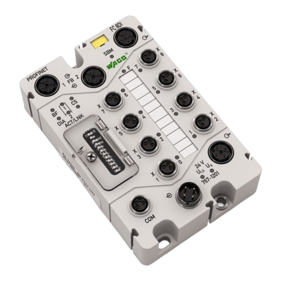
Pos : 20.8 /Serie 767 (WAGO-SPEED WAY)/Ger ätebesc hrei bung/Ansc hl üss e/F eldbus koppler/Anschl üss e - Bild @ 7\mod_1268815875579_21.doc x @ 52929 @ @ 1 Figure 2: Connectors Pos : 20.9 /Serie 767 (WAGO-SPEED WAY)/Ger ätebesc hrei bung/Ansc hl üss e/F eldbus koppler/Leg ende 767-1501 C AN open-Ansc hlüss e_1 @ 8\mod_1280924869409_21.doc x @ 62164 @ @ 1 Table 5: Legend for figure "Connectors"... -
Page 25: Marking Possibilities And Fastening
Figure 3: Marking possibilities and fastening Pos : 20.13 /Serie 767 ( WAGO-SPEED WAY)/Gerätebeschr eibung/Befestigung/F eldbus koppler/Leg ende z u Bes chriftung und Befes tigung 767- xxxx_F eldbus koppler @ 7\mod_1268815785576_21.doc x @ 52925 @ @ 1 Table 6: Legend for figure “Marking possibilities and fastening”... -
Page 26: Display Elements
Pos : 20.17 /Serie 767 ( WAGO-SPEED WAY)/Gerätebeschr eibung/Anz eigeel emente/F eldbus koppler /Legende zu Anzeig eel emente 767- xxxx, Pos. 15- 19: Status SBM, F, D I, U A und ULS @ 7\mod_1268815898392_21.doc x @ 52953 @ @ 1... - Page 27 767-1501 FC CANopen 8DI 24V DC Pos : 20.20 /Serie 767 ( WAGO-SPEED WAY)/Gerätebeschr eibung/Anz eigeel emente/F eldbus koppler /Legende zu Anzeig eel emente 767-1501, Pos . 21: Status F eldbus + Hi nweis @ 8\mod_1280925334123_21.doc x @ 62182 @ @ 1...
-
Page 28: Operating Elements
Figure 5: DIP switch. All switches are set on "Off" at delivery Pos : 20.25 /Serie 767 ( WAGO-SPEED WAY)/Gerätebeschr eibung/Bedi enel emente/F eldbus koppler/Di p-Sc halter 767- 1501, - 2501, Legende Pos. 1-9: Adresse und Baudr ate @ 9\mod_1281621226678_21.doc x @ 63500 @ @ 1... - Page 29 No function. Pos : 20.28 /Serie 767 ( WAGO-SPEED WAY)/Gerätebeschr eibung/Bedi enel emente/F eldbus koppler/Di p-Sc halter 767- 1301, - 2301, - 1501, 2501, Legende Pos. 11+12: R es et @ 8\mod_1281358783611_21.doc x @ 62673 @ @ 1 This DIP switch must always be set to „Off“.
-
Page 30: Labeling
Pos : 20.30 /Alle Serien (Allgemeine M odul e)/Übersc hriften/Neue Ü bersc hriften/Ebene 2Bedruc kung - Übersc hrift 2 @ 4\mod_1241082409515_21.doc x @ 32035 @ 2 @ 1 Labeling Pos : 20.31 /Serie 767 ( WAGO-SPEED WAY)/Gerätebeschr eibung/Bedr uc kung/F el dbus koppl er/Bedr uc kung 767- 1501 - Bild @ 8\mod_1280927851578_21.doc x @ 62195 @ @ 1 Figure 6: Labeling on the Back Side Pos : 20.32 /Serie 767 ( WAGO-SPEED WAY)/Gerätebeschr eibung/Bedr uc kung/F el dbus koppl er/Bedr uc kung Rüc kseite - Legende @ 7\mod_1268815939674_21.doc x @ 52973 @ @ 1... -
Page 31: Figure 7: Label On Fieldbus Coupler
• SN: Serial number (50) Pos : 20.36 /Serie 767 ( WAGO-SPEED WAY)/Gerätebeschr eibung/Bedr uc kung/F el dbus koppl er/Bedr uc kung seitlic h_2 (wenn kei ne MAC-ID vorhanden) @ 8\mod_1280913507607_21.doc x @ 62100 @ @ 1 • Manufacturing number (51) Pos : 20.37 /Serie 767 ( WAGO-SPEED WAY)/Gerätebeschr eibung/Bedr uc kung/F el dbus koppl er/Bedr uc kung seitlic h - Bild @ 7\mod_1269261873652_21.doc x @ 53698 @ @ 1... -
Page 32: Schematic Diagram
Schematic Diagram Pos : 20.41 /Serie 767 ( WAGO-SPEED WAY)/Gerätebeschr eibung/Sc hematis che Sc haltbilder/F eldbus koppler/Einl eitung z um schematisc hen Sc haltbild FBK @ 10\mod_1308561496197_21.doc x @ 73710 @ @ 1 The following schematic diagram provides an overview of the power supply and principle of operation of the power supply connections, as well as the digital inputs of the fieldbus coupler (see also section “Connecting the Supply Cable”... -
Page 33: Dimensions
Pos : 20.44 /Alle Serien (Allgemeine M odul e)/Übersc hriften/Neue Ü bersc hriften/Ebene 2Abmess ung en - Übersc hrift 2 @ 5\mod_1248869612468_21.doc x @ 39441 @ 2 @ 1 Dimensions Pos : 20.45 /Serie 767 ( WAGO-SPEED WAY)/Gerätebeschr eibung/Abmessungen/F eldbus koppler/Abmes sungen - Bild @ 7\mod_1268815951549_21.doc x @ 52977 @ @ 1 Figure 9: Dimensions of fieldbus coupler in mm Pos : 20.46 /D okumentati on allgemei n/Gli ederungsel emente/---Seitenwec hs el--- @ 3\mod_1221108045078_0.doc x @ 21810 @ @ 1... -
Page 34: Technical Data
35.7 mm Length 117 mm Pos : 20.49.2 /Serie 767 ( WAGO-SPEEDWAY)/Gerätebeschr eibung/Tec hnisc he D aten/F eldbus koppler/767- 1201, 1501 Ger ätedaten_2 @ 8\mod_1279278572211_21.doc x @ 60218 @ @ 1 Weight Approx. 377 g Pos : 20.49.3 /Serie 767 ( WAGO-SPEEDWAY)/Gerätebeschr eibung/Tec hnisc he D aten/F eldbus koppler/Sys temdaten 767- 1501 @ 8\mod_1280929824614_21.doc x @ 62252 @ 3 @ 1 4.8.2... -
Page 35: Supply
Wrong connection of inputs No effect Pos : 20.49.11 /Seri e 767 ( WAGO- SPEED WAY)/Ger ätebesc hrei bung/T ec hnis che D aten/Fel dbus koppl er/Par ametri erbare Funkti onen @ 8\mod_1279279041466_21.doc x @ 60241 @ 3 @ 1 Manual... -
Page 36: Configurable Functions
(only via FDT/DTM) Diagnostics (per module) Enable/disable Pos : 20.49.12 /Seri e 767 ( WAGO- SPEED WAY)/Ger ätebesc hrei bung/T ec hnis che D aten/Fel dbus koppl er/Diag nose @ 8\mod_1279279547751_21.doc x @ 60244 @ 3 @ 1 4.8.7 Diagnostics Table 18: Technical Data –... -
Page 37: Process Image
767-1501 FC CANopen 8DI 24V DC Pos : 20.49.14 /Seri e 767 ( WAGO- SPEED WAY)/Ger ätebesc hrei bung/T ec hnis che D aten/Fel dbus koppl er/Proz ess abbild 767-1501, - 2501 @ 13\mod_1355755243543_21.doc x @ 107740 @ 3 @ 1 4.8.8... -
Page 38: Approvals
Approvals Pos : 20.49.19.2 /Serie 767 ( WAGO- SPEED WAY)/Ger ätebesc hrei bung/Z ulas sungen/Z ulassungen F Bkoppler 767- xxxx Allgemei n, ohne Vari antenangabe - Einl eitung @ 22\mod_1427971356549_21.doc x @ 179556 @ @ 1 The following approvals have been granted to 767-1501 fieldbus coupler: Pos : 20.49.19.3.1 /Alle Seri en (Allgemei ne D okumente) (Allgemei ne M odule)/Z ul ass ungen/Standardz ul assungen/C E ( Konformi täts kennz eichnung) @ 3\mod_1224494777421_21.doc x @ 24276 @ @ 1... -
Page 39: Standards And Guidelines
Pos : 20.49.22 /Seri e 767 ( WAGO- SPEED WAY)/Ger ätebesc hrei bung/N or men und Ric htli nien/N ormen und Ric htli nien F Bkoppler 767- xxxx, ohne Vari antenangabe - Einl eitung @ 22\mod_1427980077491_21.doc... -
Page 40: Mounting
Mounting Pos : 23.1 /Serie 767 (WAGO-SPEED WAY)/M ontier en/Fel dbus koppl er/Montage_Ei nlei tung 767- xxxx_Fel dbus koppl er @ 7\mod_1268894154609_21.doc x @ 53410 @ @ 1 The fieldbus coupler can be fastened directly to your system using screws. It can also be mounted on a carrier rail using an adapter (WAGO accessory) or fastened to a profile rail using a surface mounting profile (WAGO accessory). - Page 41 Mounting 767-1501 FC CANopen 8DI 24V DC Pos : 23.4 /Serie 767 (WAGO-SPEED WAY)/M ontier en/Fel dbus koppl er/Hinweis: Montage_Ei nbaulage_767- xxxx_F eldbus koppler @ 22\mod_1428401607650_21.doc x @ 179732 @ @ 1 Any mounting position is possible. Ensure a safe mounting position! In explosion hazardous environments no increased mechanical loads must be present at the installation location.
-
Page 42: Tools And Accessories Required For Mounting
767-1501 FC CANopen 8DI 24V DC Pos : 23.6 /Serie 767 (WAGO-SPEED WAY)/M ontier en/Fel dbus koppl er/Montage_Wer kz eug 767- xxxx_Fel dbus koppl er @ 7\mod_1268894155891_21.doc x @ 53422 @ 2 @ 1 Tools and Accessories Required for Mounting Depending on the mounting type, the following tools are required for installation: •... -
Page 43: Direct Mounting On Your System
M4x12 screws via the three mounting holes. Pos : 23.11 /Serie 767 ( WAGO-SPEED WAY)/Monti eren/F eldbus koppler/M ontage_Dir ektmontag e 767- xxxx_F eldbus koppler - Bild @ 7\mod_1268894152578_21.doc x @ 53390 @ @ 1 Figure 10: Mounting the fieldbus coupler on the grounded system Pos : 23.12 /D okumentati on allgemei n/Gli ederungsel emente/---Seitenwec hs el--- @ 3\mod_1221108045078_0.doc x @ 21810 @ @ 1... -
Page 44: Mounting On A Carrier Rail (Only With Wago Accessories)
Pos : 23.14 /Serie 767 ( WAGO-SPEED WAY)/Monti eren/F eldbus koppler/M ontage auf Tr agschi ene 767- xxxx_F eldbus koppler - Bil d @ 7\mod_1268894149734_21.doc x @ 53362 @ @ 1 Figure 11: Fastening the fieldbus coupler to the carrier rail adapter Pos : 23.15 /D okumentati on allgemei n/Gli ederungsel emente/---Seitenwec hs el--- @ 3\mod_1221108045078_0.doc x @ 21810 @ @ 1... -
Page 45: Fastening The Fieldbus Coupler With Carrier Rail Adapter To A Carrier Rail
(item no.: 249-116 or 249-117) for stabilization is required. Pos : 23.17 /Serie 767 ( WAGO-SPEED WAY)/Monti eren/F eldbus koppler/M ontage_Befestigung auf Tragsc hienenadapter 767- xxxx_Fel dbus koppl er - Bild @ 7\mod_1268905883023_21.doc x @ 53430 @ @ 1 Figure 12: Mounting the carrier rail adapter Pos : 23.18 /D okumentati on allgemei n/Gli ederungsel emente/---Seitenwec hs el--- @ 3\mod_1221108045078_0.doc x @ 21810 @ @ 1... -
Page 46: Mounting On A Profile Rail (Only With Wago Accessories)
Pos : 23.20 /Serie 767 ( WAGO-SPEED WAY)/Monti eren/F eldbus koppler/M ontage an ei ner Pr ofilsc hiene 767-xxxx_Fel dbus koppl er - Bild @ 7\mod_1268894148922_21.doc x @ 53354 @ @ 1 Figure 13: Fastening the fieldbus coupler to the profile adapter Pos : 23.21 /D okumentati on allgemei n/Gli ederungsel emente/---Seitenwec hs el--- @ 3\mod_1221108045078_0.doc x @ 21810 @ @ 1... -
Page 47: Fastening The Fieldbus Coupler With Profile Adapter To A Profile Rail
767-1501 FC CANopen 8DI 24V DC Pos : 23.22 /Serie 767 ( WAGO-SPEED WAY)/Monti eren/F eldbus koppler/M ontage mit Pr ofiladapter an ei ner Pr ofilsc hiene 767-xxxx_Fel dbus koppl er @ 7\mod_1268894150094_21.doc x @ 53366 @ 3 @ 1 5.5.2... -
Page 48: Replacing The Marker Card And Strip
New cards, strips and pens can be obtained from WAGO. Pos : 23.25 /Serie 767 ( WAGO-SPEED WAY)/Monti eren/F eldbus koppler/M ontage_Besc hriftung austausc hen 767- xxxx_Fel dbus koppl er - Bild @ 7\mod_1268894151750_21.doc x @ 53382 @ @ 1 Figure 14: Replacing the marker card and strip Pos : 23.26 /D okumentati on allgemei n/Gli ederungsel emente/---Seitenwec hs el--- @ 3\mod_1221108045078_0.doc x @ 21810 @ @ 1... -
Page 49: Mounting The Spacer In The Case Of Compact Arrangement
M4 screws via the mounting holes. Pos : 23.28 /Serie 767 ( WAGO-SPEED WAY)/Monti eren/F eldbus koppler/M ontage_Di stanzs tüc k T eil 1_767- xxxx_F eldbus koppler - Bild @ 7\mod_1268894153437_21.doc x @ 53398 @ @ 1 Figure 15: Attaching a spacer Pos : 23.29 /D okumentati on allgemei n/Gli ederungsel emente/---Seitenwec hs el--- @ 3\mod_1221108045078_0.doc x @ 21810 @ @ 1... -
Page 50: Figure 16: Attaching Another 767 Component To The Fieldbus Coupler
Pos : 23.31 /Serie 767 ( WAGO-SPEED WAY)/Monti eren/F eldbus koppler/M ontage_Di stanzs tüc k T eil 2_767- xxxx_F eldbus koppler - Bild @ 7\mod_1268894154219_21.doc x @ 53406 @ @ 1 Figure 16: Attaching another 767 component to the fieldbus coupler Pos : 24 /D okumentation allgemei n/Glieder ungs elemente/---Seitenwechs el--- @ 3\mod_1221108045078_0.doc x @ 21810 @ @ 1... -
Page 51: Connecting Data And Supply Cables
767-1501 FC CANopen 8DI 24V DC Pos : 25.1 /Serie 767 (WAGO-SPEED WAY)/Ans chl uss D aten- und Vers orgungs kabel/I/O-Modul e/01_Ansc hl uss der Daten- und Vers orgungs kabel - Übersc hrift 1 @ 8\mod_1278310189976_21.doc x @ 58919 @ 1 @ 1 Connecting Data and Supply Cables Pos : 25.2 /Serie 767 (WAGO-SPEED WAY)/Ans chl uss D aten- und Vers orgungs kabel/I/O-Modul e/02_Hinweis e - Ü... -
Page 52: Required Accessories
Observe the correct layout of the potential equalization. Pos : 25.8 /Serie 767 (WAGO-SPEED WAY)/Ans chl uss D aten- und Vers orgungs kabel/Fel dbus koppl er/Ansc hluss_Hi nweise Teil 3 (nic ht 767- 1401) @ 7\mod_1268909851033_21.doc x @ 53534 @ @ 1 •... -
Page 53: Connecting The Fieldbus Cable
767-1501 FC CANopen 8DI 24V DC Pos : 25.12 /Serie 767 ( WAGO-SPEED WAY)/Ansc hluss D aten- und Versorgungs kabel/F eldbus koppler/0_Ansc hlus s_F eldbus kabel anschli eßen - Übersc hrift 2 @ 8\mod_1281001995154_21.doc x @ 62338 @ 2 @ 1 Connecting the Fieldbus Cable Pos : 25.13 /Serie 767 ( WAGO-SPEED WAY)/Ansc hluss D aten- und Versorgungs kabel/F eldbus koppler/Ansc hluss _C ANopen-Kabel 767- 1501_T ext1 @ 8\mod_1281003907547_21.doc x @ 62341 @ 3 @ 1... -
Page 54: Connecting The Fieldbus Coupler To A Can Network
(2) and tighten it. Pos : 25.14 /Serie 767 ( WAGO-SPEED WAY)/Ansc hluss D aten- und Versorgungs kabel/F eldbus koppler/Ansc hluss _F eldbus kabel 767-1101, -1401, -1501, -2501 Bild 1 @ 8\mod_1279876803913_21.doc x @ 61018 @ @ 1 Figure 17: Connecting fieldbus to a fieldbus coupler Pos : 25.15 /D okumentati on allgemei n/Gli ederungsel emente/---Seitenwec hs el--- @ 3\mod_1221108045078_0.doc x @ 21810 @ @ 1... -
Page 55: Connecting Several Fieldbus Couplers Within A Can Network
Pos : 25.17 /Serie 767 ( WAGO-SPEED WAY)/Ansc hluss D aten- und Versorgungs kabel/F eldbus koppler/Ansc hluss _F eldbus kabel 767-1101, -1401, -1501, 2501 Bild 2 @ 8\mod_1279877090755_21.doc x @ 61026 @ @ 1 Figure 18: Two fieldbus couplers within one fieldbus network Pos : 25.18 /D okumentati on allgemei n/Gli ederungsel emente/---Seitenwec hs el--- @ 3\mod_1221108045078_0.doc x @ 21810 @ @ 1... -
Page 56: Connecting The S-Bus Cable
WAGO-SPEEDWAY 767 767-1501 FC CANopen 8DI 24V DC Pos : 25.19 /Serie 767 ( WAGO-SPEED WAY)/Ansc hluss D aten- und Versorgungs kabel/F eldbus koppler/Ansc hluss _S-BUS allgemein @ 7\mod_1268906368415_21.doc x @ 53454 @ 2 @ 1 Connecting the S-BUS Cable The S-BUS is used for communication between the fieldbus coupler and the connected I/O modules. -
Page 57: Figure 19: S-Bus Is Connected To Fieldbus Coupler And I/O Modules
(2) of the fieldbus coupler. Pos : 25.21 /Serie 767 ( WAGO-SPEED WAY)/Ansc hluss D aten- und Versorgungs kabel/F eldbus koppler/Ansc hluss _S-BUS 767-1101 - Bild @ 7\mod_1268906368977_21.doc x @ 53458 @ @ 1 Figure 19: S-BUS is connected to fieldbus coupler and I/O modules Pos : 25.22 /D okumentati on allgemei n/Gli ederungsel emente/---Seitenwec hs el--- @ 3\mod_1221108045078_0.doc x @ 21810 @ @ 1... -
Page 58: Connecting The Supply Cable
WAGO-SPEEDWAY 767 767-1501 FC CANopen 8DI 24V DC Pos : 25.23 /Serie 767 ( WAGO-SPEED WAY)/Ansc hluss D aten- und Versorgungs kabel/F eldbus koppler/Ansc hluss _Spannungs vers orgung @ 7\mod_1268906369493_21.doc x @ 53462 @ 2 @ 1 Connecting the Supply Cable The supply cable provides power to the fieldbus coupler and the connected I/O modules. -
Page 59: Figure 20: Supply Cable Connected With Fieldbus Coupler And I/O Modules
Tighten the plugs and sockets using the knurled-head screw. Pos : 25.24 /Serie 767 ( WAGO-SPEED WAY)/Ansc hluss D aten- und Versorgungs kabel/F eldbus koppler/Ansc hluss _Spannungs vers orgung - Bild @ 7\mod_1268906370024_21.doc x @ 53466 @ @ 1 Figure 20: Supply cable connected with fieldbus coupler and I/O modules Pos : 25.25 /D okumentati on allgemei n/Gli ederungsel emente/---Seitenwec hs el--- @ 3\mod_1221108045078_0.doc x @ 21810 @ @ 1... -
Page 60: Connecting The Sensor Cables
X1, X3, X5, X7 X2, X4, X6, X8 Pos : 25.27 /Serie 767 ( WAGO-SPEED WAY)/Wichtige Erläuter ung en/Sic herheits hinweise/Ac htung/Ac htung: Höchs te Strombel astbar bei t der Vers .kontakte( Sens oren) und Sens orstromaufnahme 400 mA @ 8\mod_1278305007084_21.doc x @ 58890 @ @ 1... -
Page 61: Figure 21: Digital Inputs
Screw a protective cap on all unused input sockets to ensure that IP67 degree of protection is provided. Pos : 25.30 /Serie 767 ( WAGO-SPEED WAY)/Ansc hluss D aten- und Versorgungs kabel/F eldbus koppler/Ansc hluss _Sens oren - Bild @ 7\mod_1268906365883_21.doc x @ 53434 @ @ 1 Figure 21: Digital inputs Pos : 25.31 /D okumentati on allgemei n/Gli ederungsel emente/---Seitenwec hs el--- @ 3\mod_1221108045078_0.doc x @ 21810 @ @ 1... -
Page 62: Connecting The Usb Cable
WAGO-SPEEDWAY 767 767-1501 FC CANopen 8DI 24V DC Pos : 25.32 /Serie 767 ( WAGO-SPEED WAY)/Ansc hluss D aten- und Versorgungs kabel/F eldbus koppler/Ansc hluss _U SB 1 @ 7\mod_1268916382387_21.doc x @ 53560 @ 2 @ 1 Connecting the USB Cable... -
Page 63: Figure 22: Usb Interface
767-1501 FC CANopen 8DI 24V DC Pos : 25.39 /Serie 767 ( WAGO-SPEED WAY)/Ansc hluss D aten- und Versorgungs kabel/F eldbus koppler/Ansc hluss _U SB 5_2 @ 8\mod_1279087307901_21.doc x @ 59883 @ @ 1 Connect your PC with the fieldbus coupler by inserting the USB cable plug into the fieldbus coupler's USB connection COM (7) and tightening it. -
Page 64: Commissioning
The CAN terminator is fastened (see Section "Connection to the Data and Supply Cable"). Pos : 27.5 /Serie 767 (WAGO-SPEED WAY)/In Betrieb nehmen/Fel dbus koppl er/Inbetri ebnahme 767-1201, -1301, -1311, - 1401, -1501 @ 8\mod_1279524134190_21.doc x @ 60324 @ @ 1 •... -
Page 65: Setting The Canopen Station Address
767-1501 FC CANopen 8DI 24V DC Pos : 27.7 /Serie 767 (WAGO-SPEED WAY)/In Betrieb nehmen/Fel dbus koppl er/Ei nstellen der CAN open-Adress e 767- 1501, - 2301 1 @ 9\mod_1281688560278_21.doc x @ 63600 @ 2 @ 1 Setting the CANopen Station Address... -
Page 66: Figure 23: Dip Switch Set For Station Address 52
= 4 + 16 + 32 = 52). Pos : 27.10 /Serie 767 ( WAGO-SPEED WAY)/In Betrieb nehmen/F eldbus koppler/Einstellen der C ANopen- Adr ess e 767-1501 Bild @ 15\mod_1365609792783_21.doc x @ 116935 @ @ 1 Figure 23: DIP switch set for station address 52 Pos : 27.11 /D okumentati on allgemei n/Gli ederungsel emente/---Seitenwec hs el--- @ 3\mod_1221108045078_0.doc x @ 21810 @ @ 1... -
Page 67: Setting The Baud Rate
Commissioning 767-1501 FC CANopen 8DI 24V DC Pos : 27.12 /Serie 767 ( WAGO-SPEED WAY)/In Betrieb nehmen/F eldbus koppler/Einstellen der Baudrate 767- 1501, - 2501 @ 8\mod_1281010372632_21.doc x @ 62425 @ 2 @ 1 Setting the Baud Rate The fieldbus coupler's baud rate can be set via switches 8 and 9. You have the choice between 125kbit/s, 500kbit/s and 1Mbit/s, or you may choose automatic baud rate detection. -
Page 68: Figure 24: Dip Switches Set For A 500Kbit/S Baud Rated
767-1501 FC CANopen 8DI 24V DC Pos : 27.14 /Serie 767 ( WAGO-SPEED WAY)/In Betrieb nehmen/F eldbus koppler/Einstellen der Baudrate 767- 1501 Bild @ 15\mod_1365610317508_21.doc x @ 116943 @ @ 1 Figure 24: DIP switches set for a 500kbit/s baud rated Pos : 27.15 /D okumentati on allgemei n/Gli ederungsel emente/---Seitenwec hs el--- @ 3\mod_1221108045078_0.doc x @ 21810 @ @ 1... -
Page 69: Switching On The Fieldbus Coupler
The fieldbus coupler and all connected I/O modules are ready for operation after the initialization phase. Pos : 27.17 /Serie 767 ( WAGO-SPEED WAY)/Wichtige Erläuter ung en/Sic herheits hinweise/Hinweis/Hi nweis : Kei ne 767- Komp. entfer nen @ 8\mod_1279526731811_21.doc x @ 60342 @ @ 1 Disruption during operation None of the 767 Series devices are to be removed or added during operation, as this causes a disruption in the 767 station. -
Page 70: Configuration
Pos : 29 /All e Seri en (Allgemei ne Module)/Ü berschriften/N eue Ü berschriften/Ebene 1Konfig urieren - Ü berschrift 1 @ 5\mod_1247578046546_21.doc x @ 37410 @ 1 @ 1 Configuration Pos : 30 /Serie 767 ( WAGO-SPEED WAY)/Konfiguri eren/F eldbus koppler/Konfig urieren_767- 1501, - 2501 T eil 1 @ 9\mod_1281692942044_21.doc x @ 63639 @ 2 @ 1 This section contains all information required for configuration of the 767 components for CANopen. -
Page 71: Eds Files
Configuration 767-1501 FC CANopen 8DI 24V DC Pos : 32 /Serie 767 ( WAGO-SPEED WAY)/Konfiguri eren/F eldbus koppler/Konfig urieren_767- 1501, - 2501 T eil 3 @ 9\mod_1281692957498_21.doc x @ 63643 @ 2 @ 1 EDS Files The EDS files (standard and modular) contain the characteristics of the fieldbus coupler and information regarding its communication capabilities. -
Page 72: Figure 26: Example Of Codesys Controller Configuration 2
Enter the desired modules into the "Selected Modules" window following the item-oriented modules. Figure 26: Example of CODESYS controller configuration 2 (fieldbus coupler as slave on WAGO-I/O-IPC) Pos : 33 /D okumentation allgemei n/Glieder ungs elemente/---Seitenwechs el--- @ 3\mod_1221108045078_0.doc x @ 21810 @ @ 1 Manual... -
Page 73: Pdo Mapping
Configuration 767-1501 FC CANopen 8DI 24V DC Pos : 34 /Serie 767 ( WAGO-SPEED WAY)/Konfiguri eren/F eldbus koppler/Konfig urieren_767- 1501, - 2501 PDO-Mapping @ 8\mod_1281011538855_21.doc x @ 62439 @ 23322222 @ 1 PDO Mapping Mapping (configuring) the process data objects (PDO), determines which data the fieldbus coupler is exchanging with other CANopen devices on the CAN bus using the PDO. -
Page 74: Default Pdo Mapping
Configuration WAGO-SPEEDWAY 767 767-1501 FC CANopen 8DI 24V DC 8.3.1 Default PDO Mapping After switching on the fieldbus coupler, the coupler configures the first four PDOs with the process data of the I/O modules. The digital data is entered into the first PDO, the analog data into PDOs 2 –... -
Page 75: Table 31: 2Nd Rxpdo
WAGO-SPEEDWAY 767 Configuration 767-1501 FC CANopen 8DI 24V DC RxPDO: The second RxPDO contains the process data from the first four outputs, which have a data width of 16 bits each. These outputs may be linked to different I/O modules. The important component is a data width of 16 bits per output. -
Page 76: Table 32: 3Rd Rxpdo
Configuration WAGO-SPEEDWAY 767 767-1501 FC CANopen 8DI 24V DC RxPDO: The third RxPDO contains the process data from outputs 5 – 8, which have a data width of 16 bits each. If no more than four 16 bit wide outputs are connected to the fieldbus coupler, sub-index 0 contains the value 0;... -
Page 77: Table 33: 4Th Rxpdo
WAGO-SPEEDWAY 767 Configuration 767-1501 FC CANopen 8DI 24V DC RxPDO: The fourth RxPDO contains the process data from outputs 9 – 12, which have a data width of 16 bits each. If no more than eight 16 bit wide outputs are connected to the fieldbus coupler, sub-index 0 contains the value 0;... -
Page 78: Table 34: 1St Txpdo
Configuration WAGO-SPEEDWAY 767 767-1501 FC CANopen 8DI 24V DC TxPDO: The process data of the digital inputs are combined into bytes from blocks of 8 bits. The first TxPDO contains the data from the first eight digital input blocks. If no digital inputs are connected to the fieldbus coupler, sub-index 0 contains the value 0;... -
Page 79: Table 35: 2Nd Txpdo
WAGO-SPEEDWAY 767 Configuration 767-1501 FC CANopen 8DI 24V DC TxPDO: The second TxPDO contains the data from the first four inputs, which have a data width of 16 bits each. These channels may be linked to different I/O modules. The important component is a data width of 16 bits per channel. -
Page 80: Table 36: 3Rd Txpdo
Configuration WAGO-SPEEDWAY 767 767-1501 FC CANopen 8DI 24V DC TxPDO: The third TxPDO contains the process data from analog inputs 5 – 8, which have a data width of 16 bits each. If no more than four 16 bit wide inputs are connected to the fieldbus coupler, sub-index 0 contains the value 0;... -
Page 81: Table 37: 4Th Txpdo
WAGO-SPEEDWAY 767 Configuration 767-1501 FC CANopen 8DI 24V DC TxPDO: The fourth TxPDO contains the process data from analog inputs 9 – 12, which have a data width of 16 bits each. If no more than eight analog inputs are connected to the fieldbus coupler, sub-index 0 contains the value 0;... -
Page 82: Application-Specific Mapping
Configuration WAGO-SPEEDWAY 767 767-1501 FC CANopen 8DI 24V DC 8.3.2 Application-Specific Mapping In contrast to the default mapping, an application-specific PDO mapping gives you the option to specify which data is to be transferred by the PDO. This requires that the fieldbus coupler is in its pre-operational state. For more information, see Section “CANopen State Diagram”. -
Page 83: Table 41: Insert 3Rd Analog Input Channel
WAGO-SPEEDWAY 767 Configuration 767-1501 FC CANopen 8DI 24V DC Mapping parameter First enter the mapping parameter into sub-index 1 … 8, then enter the number of valid sub-indices into sub-index 0. These objects are stored using SDO transmissions: Table 41: Insert 3rd analog input channel... -
Page 84: Table 45: Deactivate Pdo
Configuration WAGO-SPEEDWAY 767 767-1501 FC CANopen 8DI 24V DC To change the communication parameters, proceed as follows: Deactivate the PDO that you wish to configure. In the example, this is TxPDO2. To do this, write the value 0x80000000 into the object with index 0x1801, sub-index 01 (“Transmit PDO Communication Parameter”). -
Page 85: Enabling The Analog Input Data
WAGO-SPEEDWAY 767 Configuration 767-1501 FC CANopen 8DI 24V DC Enabling the Analog Input Data In the default setting, the PDO transfer of analog input data is switched off. Therefore, this data is only sent once by the fieldbus coupler and is not subsequently updated. -
Page 86: Delayed I/O Module Start-Up
Configuration WAGO-SPEEDWAY 767 767-1501 FC CANopen 8DI 24V DC Delayed I/O Module Start-Up The topology of a 767 node can cause I/O modules to be delayed in starting up. So that the CANopen application is not blocked on the fieldbus coupler as a result of this delay, it starts independent of the S-BUS. -
Page 87: Figure 27: Fieldbus Coupler Response To Delayed Start-Up
WAGO-SPEEDWAY 767 Configuration 767-1501 FC CANopen 8DI 24V DC power on Basic initialisation is Systembus active? Objectdictionary without I/O-Module Data Default configuration Send Emergency: „No process data available“ Run CANopen application is Systembus active? I/O-Module Data to Objectdictionary Stored configuration? -
Page 88: S-Bus Disruption During Continuous Operation
Configuration WAGO-SPEEDWAY 767 767-1501 FC CANopen 8DI 24V DC S-BUS Disruption During Continuous Operation If a disruption of the S-BUS occurs during continuous operation, the output modules output the process value 0 (additional information can be found in the corresponding I/O module documentation). The CANopen application on the fieldbus coupler sends the error message (Emergency) 2No process data available,”... -
Page 89: Diagnostics
Diagnostics 767-1501 FC CANopen 8DI 24V DC Pos : 36 /Serie 767 ( WAGO-SPEED WAY)/F eldbus kommuni kation/Di agnose 767-1501 @ 8\mod_1281014317435_21.doc x @ 62473 @ 12 @ 1 Diagnostics This section contains all information required to analyze the CANopen diagnostic information of the 767 components. -
Page 90: Error Messages (Emergency)
WAGO-SPEEDWAY 767 767-1501 FC CANopen 8DI 24V DC Pos : 38 /Serie 767 ( WAGO-SPEED WAY)/F eldbus kommuni kation/F ehler mel dungen ( Emergenc y) 767- 1501 @ 8\mod_1281014371107_21.doc x @ 62477 @ 1 @ 1 Error Messages (Emergency) Error messages are given when an error situation arises or is resolved in the fieldbus coupler. - Page 91 WAGO-SPEEDWAY 767 Error Messages (Emergency) 767-1501 FC CANopen 8DI 24V DC Table 50: Description of error messages Bytes 0, 1 3 – 7 Name "Error "Error "Manufacturer Description code" register" - Specific Error Code" 0x8100 0x81 00 04 00 00 00...
- Page 92 Error Messages (Emergency) WAGO-SPEEDWAY 767 767-1501 FC CANopen 8DI 24V DC Table 50: Description of error messages Bytes 0, 1 3 – 7 Name "Error "Error "Manufacturer Description code" register" - Specific Error Code" 0x8220 0x81 00 08 SS II NN...
-
Page 93: Object Directory
Object Directory 767-1501 FC CANopen 8DI 24V DC Pos : 40 /Serie 767 ( WAGO-SPEED WAY)/F eldbus kommuni kation/Obj ektverz eichnis 767- 1501 @ 8\mod_1281014576327_21.doc x @ 62481 @ 12 @ 1 Object Directory The object directory contains all configuration information and process data from the fieldbus coupler. -
Page 94: Table 51: Structure Of Canopen Object Directory
Object Directory WAGO-SPEEDWAY 767 767-1501 FC CANopen 8DI 24V DC Each entry consists of • an object name that describes the function of the object, • a data type attribute that defines the data type of the entry • an access attribute that indicates whether the entry is only allowed to be read or written or both. -
Page 95: Communication Profile Area
WAGO-SPEEDWAY 767 Object Directory 767-1501 FC CANopen 8DI 24V DC 11.1 Communication Profile Area The following table lists all the communication profile objects that are supported by the fieldbus coupler. The detailed objects from the fieldbus coupler are covered in section "Appendix"... - Page 96 Object Directory WAGO-SPEEDWAY 767 767-1501 FC CANopen 8DI 24V DC Table 52: Communication profile objects Index Name Data Type Description Information 0x1029 Error behavior Array State change in the Unsigned8 case of error 0x1200 Server SDO parameter Record Parameter for server...
-
Page 97: Canopen State Diagram
CANopen State Diagram 767-1501 FC CANopen 8DI 24V DC Pos : 42 /Serie 767 ( WAGO-SPEED WAY)/F eldbus kommuni kation/C ANopen-Z ustands diagr amm 767-1501 @ 8\mod_1281014789688_21.doc x @ 62484 @ 12222 @ 1 CANopen State Diagram The following state diagram illustrates the individual communication states and possible transitions of CAN communication. -
Page 98: Pre-Operational
CANopen State Diagram WAGO-SPEEDWAY 767 767-1501 FC CANopen 8DI 24V DC 12.2 Pre-Operational In this state, communication can take place via SDOs. Communication via the PDO is not possible. Entries in the object directory can be read and written with the SDO. -
Page 99: Canopen Communication Objects
CANopen Communication Objects 767-1501 FC CANopen 8DI 24V DC Pos : 44 /Serie 767 ( WAGO-SPEED WAY)/F eldbus kommuni kation/C ANopen- Kommuni kati onsobjekte 767-1501, -2501 @ 8\mod_1281014949111_21.doc x @ 62498 @ 12233333322232233332333 @ 1 CANopen Communication Objects Communication with the devices takes place by means of the communication objects. -
Page 100: Service Data Object (Sdo)
CANopen Communication Objects WAGO-SPEEDWAY 767 767-1501 FC CANopen 8DI 24V DC Distinctiveness of TxPDO “Transmission Types” 254 and 255 If the “Transmission Type” for a TxPDO is set to the values 254 or 255, the TxPDO is sent by the fieldbus coupler in an event-driven manner. Device profile DS401 (“Device profile for generic I/O modules”), in which the various events... -
Page 101: Initiate Sdo Download
WAGO-SPEEDWAY 767 CANopen Communication Objects 767-1501 FC CANopen 8DI 24V DC Figure 31: RxSDO and TxSDO 13.2.1 Initiate SDO Download This protocol is used to initiate data transfer from the master to the fieldbus coupler. If the transfer contains a maximum of 4 bytes of data, this data is included in the transfer inside the protocol. -
Page 102: Table 53: Description Of "Initiate Sdo Download" Protocol
CANopen Communication Objects WAGO-SPEEDWAY 767 767-1501 FC CANopen 8DI 24V DC Table 53: Description of “Initiate SDO Download” protocol Abbreviation Term Description ccs: Client command specifier 1: “Initiate download request” scs: Server command specifier 3: “Initiate download response” Only valid when e = 1 and When n is valid, it indicates the number of bytes s = 1;... -
Page 103: Download Sdo Segment
WAGO-SPEEDWAY 767 CANopen Communication Objects 767-1501 FC CANopen 8DI 24V DC 13.2.2 Download SDO Segment If more than 4 bytes of data are to be transferred, use this protocol. Data transfer begins after the “Initiate SDO Download Protocol”, which initiates the transfer, is processed. -
Page 104: Initiate Sdo Upload
CANopen Communication Objects WAGO-SPEEDWAY 767 767-1501 FC CANopen 8DI 24V DC 13.2.3 Initiate SDO Upload This protocol is used to initiate data transfer from the fieldbus coupler to the master. If the transfer contains a maximum of 4 bytes of data, this data is included in the transfer inside the protocol. -
Page 105: Table 55: Description Of "Initiate Sdo Upload" Protocol
WAGO-SPEEDWAY 767 CANopen Communication Objects 767-1501 FC CANopen 8DI 24V DC Table 55: Description of “Initiate SDO Upload” protocol Abbreviation Term Description ccs: Client command specifier 2: “Initiate upload request” scs: Server command specifier 2: “Initiate upload response” Only valid when e = 1 and When n is valid, it indicates the number of s = 1;... -
Page 106: Upload Sdo Segment
CANopen Communication Objects WAGO-SPEEDWAY 767 767-1501 FC CANopen 8DI 24V DC 13.2.4 Upload SDO Segment If more than 4 bytes of data are to be transferred, use this protocol. It is sent following the “Initiate Upload Protocol”. Figure 35: Upload SDO Segment Table 56: Description of the “Upload SDO Segment”... -
Page 107: Abort Sdo Transfer
WAGO-SPEEDWAY 767 CANopen Communication Objects 767-1501 FC CANopen 8DI 24V DC 13.2.5 Abort SDO Transfer Use this protocol if an SDO transfer is to be aborted. Figure 36: Abort SDO Transfer Table 57: Description of the Abort SDO protocol Abbreviation... - Page 108 CANopen Communication Objects WAGO-SPEEDWAY 767 767-1501 FC CANopen 8DI 24V DC Table 59: Error messages arising from the Abort SDO protocol Byte 7 – byte 4 Description Abort Code 0604 0043 General parameter incompatibility reason 0604 0047 General internal incompatibility in the device...
-
Page 109: Examples Of Sdos
WAGO-SPEEDWAY 767 CANopen Communication Objects 767-1501 FC CANopen 8DI 24V DC 13.2.6 Examples of SDOs Four examples of SDOs are listed below in hexadecimal format. These examples show the operation of SDOs on the CAN telegram level and can prove helpful when the SDO protocol is to be implemented on a CAN PC card. -
Page 110: Table 61: Read Index 0X1008
CANopen Communication Objects WAGO-SPEEDWAY 767 767-1501 FC CANopen 8DI 24V DC Reading Index 0x1008, Sub-Index 0; “Manufacturer Device Name” Index 0x1008 has a data width of 8 bytes. The “Normal Transfer Mode” is used for transfer. In this case, three telegrams are sent for each CANopen device. -
Page 111: Node Guarding
WAGO-SPEEDWAY 767 CANopen Communication Objects 767-1501 FC CANopen 8DI 24V DC Describing Index 0x6200, Sub-Index 1; First Digital Output Block, 8 Bit The output values of the digital output modules are stored in index 0x6200. Every 8 bits are assigned to a group and can be read and written starting in sub-index 1. - Page 112 CANopen Communication Objects WAGO-SPEEDWAY 767 767-1501 FC CANopen 8DI 24V DC The states are coded as follows: Node State Value Pre-operational Operational Stopped The “Life Time” is the product of the guard time (index 0x100C) and the life time factor (index 0x100D).
-
Page 113: Heartbeat Monitoring
WAGO-SPEEDWAY 767 CANopen Communication Objects 767-1501 FC CANopen 8DI 24V DC 13.4 Heartbeat Monitoring This protocol makes it possible to carry out module monitoring without using RTR frames. The heartbeat generator generates a telegram in a cyclical manner (time interval defined in object 0x1017) from the fieldbus coupler, in which it transfers the state of the I/O module. -
Page 114: Synchronization Object, Sync
CANopen Communication Objects WAGO-SPEEDWAY 767 767-1501 FC CANopen 8DI 24V DC 13.5 Synchronization Object, SYNC This object enables the synchronization of all network devices. Through the corresponding PDO configuration, you can cause the network device to process its data or update its outputs upon arrival of a SYNC object. -
Page 115: Emergency Object (Emcy)
WAGO-SPEEDWAY 767 CANopen Communication Objects 767-1501 FC CANopen 8DI 24V DC 13.6 Emergency Object (EMCY) Emergency objects are triggered by an internal error situation; e.g., an S-BUS disruption or an I/O module error. The fieldbus coupler then sends an emergency object to all connected CANopen devices (broadcast) to notify them of the error. -
Page 116: Stop Remote Node
CANopen Communication Objects WAGO-SPEEDWAY 767 767-1501 FC CANopen 8DI 24V DC 13.7.2 Stop Remote Node This service is used to convert the NMT slave (fieldbus coupler) to the stopped state. Figure 40: Stop remote node Stop Remote Node Node ID = 0: All available CANopen devices are converted to the stopped state. -
Page 117: Reset Node
WAGO-SPEEDWAY 767 CANopen Communication Objects 767-1501 FC CANopen 8DI 24V DC 13.7.4 Reset Node This service is used to reset the NMT slave (fieldbus coupler). Figure 42: Reset node Reset Node Node ID = 0: All available CANopen devices are reset. -
Page 118: Error Control Protocols
CANopen Communication Objects WAGO-SPEEDWAY 767 767-1501 FC CANopen 8DI 24V DC 13.8 Error Control Protocols This protocol can assist in detecting errors in the network. In this way, the master can test whether a CANopen device is still in the designated state or if it has been switched to a different state (e.g., by a reset). -
Page 119: Heartbeat Protocol
WAGO-SPEEDWAY 767 CANopen Communication Objects 767-1501 FC CANopen 8DI 24V DC 13.8.2 Heartbeat Protocol This protocol enables monitoring without RTR frames. A heartbeat generator generates a heartbeat telegram in a cyclical manner that is received by all. In the heartbeat telegram, the current state of the generator is coded. -
Page 120: Diagnostics
WAGOframe. For more information, see section “Readout of Blink Codes using WAGO DTMs”. Pos : 47.3 /Serie 767 (WAGO-SPEED WAY)/Di agnose/Fel dbus koppl er/Statusmel dungen Einl eitung 767-1501 @ 8\mod_1281074751693_21.doc x @ 62540 @ 2 @ 1 14.2... -
Page 121: Table 65: Status Messages Of The Err Led
WAGO-SPEEDWAY 767 Diagnostics 767-1501 FC CANopen 8DI 24V DC The following tables contain the descriptions of the CANopen-specific LEDs "ERR" and "RUN." If CANopen-specific errors arise, they are signaled via the ERR LED. The errors are classified according to priority. The ERR LED uses a "red, flickering" blink sequence to signal an error with the lowest priority;... -
Page 122: Table 66: Status Messages Of The Run Led
Diagnostics WAGO-SPEEDWAY 767 767-1501 FC CANopen 8DI 24V DC Table 66: Status messages of the RUN LED Color Cause Remedy/information If no other LEDs light up, power is not being supplied to the unit. Turn on the power supply. Green, blinking... -
Page 123: Operational Messages Of The Fieldbus Coupler
Information regarding remedies of certain causes is also provided. Pos : 47.8 /Serie 767 (WAGO-SPEED WAY)/Wic htige Erläuterungen/Sicherheits hinweis e/Hi nweis /Hinweis: 767- 1xxx/- 2xxx/-3xxx Betri ebs mel dungen D eakti vier bar e Di agnosen @ 7\mod_1265892285078_21.doc x @ 50336 @ @ 1 Disable diagnoses Use the diagnostic overview (see section “Parameterizing”... - Page 124 Diagnostics WAGO-SPEEDWAY 767 767-1501 FC CANopen 8DI 24V DC Actuator supply is not Connect the power supply and present. check the voltage level, if applicable. Green Logic supply and sensor supply are present. Logic supply and sensor Connect the power supply and supply are not present.
-
Page 125: Error Messages From The Fieldbus Coupler Via Led Signals
767-1501 FC CANopen 8DI 24V DC Pos : 47.11 /Serie 767 ( WAGO-SPEED WAY)/Diag nos e/F eldbus koppler /Stör mel dungen C S-LED 767- 1201, - 1301, 1401, - 1501 @ 8\mod_1279544139476_21.doc x @ 60485 @ 2 @ 1 14.4... -
Page 126: Progression Of Blink Sequence
Diagnostics WAGO-SPEEDWAY 767 767-1501 FC CANopen 8DI 24V DC 14.4.1 Progression of Blink Sequence The following table outlines the progression of the blink codes over time. If there is no number in the second position (“1” in the number “10”) or third position (“1”... -
Page 127: Example Of An Error Message Via Blink Code
WAGO-SPEEDWAY 767 Diagnostics 767-1501 FC CANopen 8DI 24V DC 14.4.2 Example of an Error Message via Blink Code The following example clarifies an error message as indicated by the blink code. An S-BUS error is displayed when the software update for the sixth I/O module fails. -
Page 128: Meaning Of The Blink Codes And Procedures For Correcting Them
The errors and warnings are divided into the following error groups: Pos : 47.15 /Serie 767 ( WAGO-SPEED WAY)/Diag nos e/F eldbus koppler /Bedeutung der Blinkcodes 767-1301, 1311, 1401, - 1501, - 2301, - 2501 @ 8\mod_1279714137435_21.doc x @ 60731 @ @ 1... -
Page 129: Table 70: Group Number 1: S-Bus Error
767-1501 FC CANopen 8DI 24V DC Pos : 47.18 /Serie 767 ( WAGO-SPEED WAY)/Diag nos e/F eldbus koppler /Gruppennummer 01 - S-BU S- F ehl er (all e, auss er 767-1101, -1201) @ 10\mod_1308574813505_21.doc x @ 73724 @ @ 1... - Page 130 Diagnostics WAGO-SPEEDWAY 767 767-1501 FC CANopen 8DI 24V DC Table 70: Group Number 1: S-BUS Error Error code Error argument Cause Correction Current software is defective. S-BUS operation Perform a firmware update of the 0 … 64 only possible in recovery I/O modules.
-
Page 131: Table 71: Group Number 2: S-Bus Warnings
767-1501 FC CANopen 8DI 24V DC Pos : 47.20 /Serie 767 ( WAGO-SPEED WAY)/Diag nos e/F eldbus koppler /Gruppennummer 02 - S-BU S- War nungen alle FBK @ 10\mod_1308575081274_21.doc x @ 73748 @ @ 1 Table 71: Group Number 2: S-BUS Warnings... -
Page 132: Table 72: Group Number 5: General Internal Hardware Errors
RTC empty). Pos : 47.22 /Serie 767 ( WAGO-SPEED WAY)/Diag nos e/F eldbus koppler /Gruppennummer 07, 08 - Allgemeine Softwar e-Fehl er (alle, aus ser 767- 1101, - 1201) @ 9\mod_1281603373460_21.doc x @ 63319 @ @ 1 Table 74: Group Number 7: General Software Errors... - Page 133 1 – 31 Perform a restart by disconnecting the power supply and then reconnecting Internal fault it. If you cannot eliminate the error, please contact WAGO support. Error in the parameter database of the fieldbus coupler. Select the checkbox “Create nominal Parameter database version system configuration”...
- Page 134 Perform a restart by disconnecting the power supply and then reconnecting Internal fault it. If you are unable to correct the problem using the aforementioned measures, contact WAGO Support. The saved parameters cannot be transferred to the I/O module because: - There is an incompatible...
-
Page 135: Table 75: Group Number 8: General Software Warnings
Pos : 47.23 /Serie 767 ( WAGO-SPEED WAY)/Diag nos e/F eldbus koppler /Gruppennummer 09 - Spezifisc he, betri ebsi nterne H ardware-F ehler (all e F BK auß er 767-1311) @ 10\mod_1308722160535_21.doc x @ 73954 @ @ 1... -
Page 136: Table 77: Group Number 11: Canopen-Specific Errors
767-1501 FC CANopen 8DI 24V DC Pos : 47.25 /Serie 767 ( WAGO-SPEED WAY)/Diag nos e/F eldbus koppler /Gruppennummer 11, 12 - Fel dbuss pez. Softwarefehler, Fel dbus spez. Softwarewar nungen 767-1501, -2501 @ 8\mod_1281081198540_21.doc x @ 62552 @ @ 1... -
Page 137: Table 79: Group Number 13: Firmware Loader Error
767-1501 FC CANopen 8DI 24V DC Pos : 47.27 /Serie 767 ( WAGO-SPEED WAY)/Diag nos e/F eldbus koppler /Gruppennummer 13, 14 - Firmwarefehler us w. (all e, ausser 767- 1101, - 1201) @ 7\mod_1269245082873_21.doc x @ 53660 @ @ 1... -
Page 138: Table 80: Group Number 14: Error With Firmware Download
Diagnostics WAGO-SPEEDWAY 767 767-1501 FC CANopen 8DI 24V DC Table 79: Group Number 13: Firmware Loader Error Error code Error argument Cause Correction Code processor error Perform a restart by disconnecting the power supply and then reconnecting it. Error when accessing Interrupt Controller. -
Page 139: Readout Of Blink Codes Using Wago Dtms
Diagnostics 767-1501 FC CANopen 8DI 24V DC Pos : 47.29 /Serie 767 ( WAGO-SPEED WAY)/Diag nos e/F eldbus koppler /Auslesen des Bli nkc odes ohne WBM @ 8\mod_1279543873995_21.doc x @ 60478 @ 2 @ 1 14.5 Readout of Blink Codes using WAGO DTMs Error messages or warnings from the fieldbus coupler are also displayed in WAGOframe under the “Blink code”... -
Page 140: Parameterizing
Pos : 49 /All e Seri en (Allgemei ne Module)/Ü berschriften/N eue Ü berschriften/Ebene 1Par ametrieren - Übersc hrift 1 @ 3\mod_1223554593484_21.doc x @ 23717 @ 1 @ 1 Parameterizing Pos : 50.1 /Serie 767 (WAGO-SPEED WAY)/Par ametrieren/F eldbus koppler /FDT/FDT /DTM allgemei n @ 17\mod_1382419422770_21.doc x @ 134740 @ 22223333233 @ 1 This section explains device parameterization with the help of an FDT border application (FDT/DTM) using WAGOframe. -
Page 141: Installing The Fdt/Dtm Components
When using another FDT/DTM frame application, install only the USB driver (item no.: 759-922), the Service Interface DTM (item no.: 759-371) and the WAGO DTM (item no.: 759-361) on your computer. These can be obtained on the Internet at www.wago.com. -
Page 142: Figure 51: Window For Product Selection 1
• WAGOframe (installation is only necessary if an FDT/DTM border application has been installed on your PC), 759-370 • WAGO service interface DTM, 759-371 • DTM for the fieldbus coupler and I/O modules, 759-361 • DTM for the system update, 759-362 Manual Version 2.2.0... -
Page 143: Figure 52: Window For Product Selection 2
WAGO-SPEEDWAY 767 Parameterizing 767-1501 FC CANopen 8DI 24V DC Figure 52: Window for product selection 2 After installing all necessary 767 programs connect your computer with the fieldbus coupler via the USB cable. See also section “Connecting Data and Supply Cables” > “Connecting the USB Cable”. -
Page 144: Starting Wagoframe
Figure 53: WAGOframe logo You can also start WAGOframe from the start menu of your operating system by clicking on “Start” and selecting Programs > WAGO Software > WAGOframe. When the “Device Selection Wizard” opens, select “Expert Mode”. The “Point to Point Mode”... -
Page 145: Expansion Of Device Catalog To Include 767 Components
WAGO-SPEEDWAY 767 Parameterizing 767-1501 FC CANopen 8DI 24V DC Figure 55: “Query WAGOframe” dialog box (exemplary) 15.3 Expansion of Device Catalog to include 767 Components WAGOframe automatically detects newly installed DTMs at the next start-up. To expand the device catalog, proceed as follows: To update the device catalog, navigate to the menu bar and select View >... -
Page 146: Setting Up Network Manually
Parameterizing WAGO-SPEEDWAY 767 767-1501 FC CANopen 8DI 24V DC 15.4 Setting Up Network Manually In order to work with the 767 components, the exact node structure topology must be copied into the “Network View” of WAGOframe. Setting up the network Depending on the application, you can create the network manually (see this section), automatically (see section “Set up network automatically”... -
Page 147: Figure 58: Selecting The Communication Dtm (Example)
WAGO-SPEEDWAY 767 Parameterizing 767-1501 FC CANopen 8DI 24V DC In the “Add” dialog box, select “WAGO Service Speedway”. Click [OK] to confirm your selection. Figure 58: Selecting the communication DTM (example) Manual Version 2.2.0... -
Page 148: Selecting The Communications Interface For Wagoframe
USB interface. For more information, see section “Connection to the Data and Supply Cable” > “Connecting the USB Cable”. Double-click on the “WAGO Service Speedway” DTM in the “Network View” pane. The DTM for the interface configuration opens. Select the COM port that you use from the Interface selection box. If the list of available interfaces is empty, check whether the fieldbus coupler is switched on and connected to your PC via the USB cable. -
Page 149: Adding A Fieldbus Coupler
This COM port number remains constant for the fieldbus coupler currently connected. When connecting a different fieldbus coupler to the PC, the COM port also changes. In this case, “WAGO Service Speedway” attempts to select the new COM port automatically. If several fieldbus couplers are connected to the PC, select the correct COM port. -
Page 150: Adding The I/O Modules
Parameterizing WAGO-SPEEDWAY 767 767-1501 FC CANopen 8DI 24V DC Figure 61: Adding the fieldbus coupler (example) 15.4.4 Adding the I/O Modules To incorporate the I/O modules that you use into WAGOframe, proceed as follows: Right-click on the “<Speedway:> 0767-xxxx” device driver in the “Network View”... -
Page 151: Figure 63: Selecting An I/O Module (Example)
WAGO-SPEEDWAY 767 Parameterizing 767-1501 FC CANopen 8DI 24V DC Figure 63: Selecting an I/O module (example) Repeat steps one through four until the module arrangement is concordant with your fieldbus node. In our example, two I/O modules were added. Figure 64: Two added I/O modules To avoid having to apply the physical process image of the 767 components created in WAGOframe in the “Network View”... -
Page 152: Online And Offline Parameter Setting
Parameterizing WAGO-SPEEDWAY 767 767-1501 FC CANopen 8DI 24V DC 15.5 Online and Offline Parameter Setting The options of online and offline parameter setting are available for configuring the 767 components. The offline mode enables the parameterization of a 767 component that is not yet present. In the offline mode, first store the parameters in a project and later transfer them to the 767 components. -
Page 153: Online Parameter Setting
WAGO-SPEEDWAY 767 Parameterizing 767-1501 FC CANopen 8DI 24V DC Save the configuration in a project by clicking on [Accept] and [File] > [Save]. Transfer the project file to the respective 767 component. To transfer parameters, right-click on the fieldbus coupler or on the respective I/O module and select Download Parameters to device from the context menu. -
Page 154: Figure 67: Opening The Configuration Interface (Online, Example)
Parameterizing WAGO-SPEEDWAY 767 767-1501 FC CANopen 8DI 24V DC In the context menu, select Online Parameter. The configuration interface opens with the fieldbus coupler parameters. Details on these parameters can be found in section “Parameterizing”. Figure 67: Opening the configuration interface (online, example) To configure the I/O modules, right-click on one of the I/O modules in the “Network View”. -
Page 155: The "Additional Functions" And "Scan" Selections
You can use the Service page to restore the default state for selected 767 components. Pos : 50.6 /Serie 767 (WAGO-SPEED WAY)/Par ametrieren/F eldbus koppler /Aus wahl Sc an 2 Benutzer v.+D ateis ys tem, nic ht rel evant @ 8\mod_1279533518942_21.doc x @ 60419 @ @ 1 • User administration Irrelevant. -
Page 156: Changing The Bus Address
Parameterizing WAGO-SPEEDWAY 767 767-1501 FC CANopen 8DI 24V DC Pos : 50.9 /Serie 767 (WAGO-SPEED WAY)/Par ametrieren/F eldbus koppler /Bus adr ess e änder n @ 7\mod_1269257614398_21.doc x @ 53675 @ 3 @ 1 15.6.1 Changing the Bus Address Requirement: Disconnect the communication link to the fieldbus coupler (“Go offline”... -
Page 157: Figure 69: Assigning New Bus Addresses For The I/O Modules (Example)
WAGO-SPEEDWAY 767 Parameterizing 767-1501 FC CANopen 8DI 24V DC Now select an I/O module from the “List of Bus Nodes” to which you wish to assign a new bus address. The current address is displayed in the New Bus Address field. Enter here the desired new address and click [Apply]. -
Page 158: Service Page
Parameterizing WAGO-SPEEDWAY 767 767-1501 FC CANopen 8DI 24V DC Pos : 50.11 /Serie 767 ( WAGO-SPEED WAY)/Parametrier en/F eldbus koppler/Ser vic e-Seite @ 14\mod_1359034268365_21.doc x @ 109940 @ 3 @ 1 15.6.2 Service Page The Service page is used to restore the default state for selected 767 components. -
Page 159: Set Up Network Automatically
WAGO-SPEEDWAY 767 Parameterizing 767-1501 FC CANopen 8DI 24V DC Pos : 50.13 /Serie 767 ( WAGO-SPEED WAY)/Parametrier en/F eldbus koppler/N etz wer k aufbauen und Life List @ 8\mod_1279539846181_21.doc x @ 60446 @ 33 @ 1 15.6.3 Set up network automatically This involves inserting all 767 components into the topology that are connected to the USB connection. -
Page 160: Life List
The life list is used to search for all devices connected to the S-BUS in order to select them for configuration directly. You have the option to use the “WAGO Service Speedway” DTM to search for the connected fieldbus coupler or to use the device driver for the fieldbus coupler to search for I/O modules connected to it. -
Page 161: Figure 74: Connected I/O Modules Of The Selected Fieldbus Coupler (Example)
WAGO-SPEEDWAY 767 Parameterizing 767-1501 FC CANopen 8DI 24V DC Figure 74: Connected I/O modules of the selected fieldbus coupler (example) Now select from the list those devices that you wish to carry over into the “Network View” for configuration. Click [Add Selected Nodes to Project] and then [Close]. -
Page 162: System Update
I/O modules. Pos : 50.17 /Serie 767 ( WAGO-SPEED WAY)/Wichtige Erläuter ung en/Sic herheits hinweise/Ac htung/Ac htung: Systemupdate @ 8\mod_1279112440229_21.doc x @ 59978 @ @ 1 System update! -
Page 163: Figure 75: Select Com Port
Figure 75: Select COM port Right-click on “Network” in the “Network View” window. In the context menu, select Add. The “Add...” dialog opens. Figure 76: Adding the communication DTM In the “Add” dialog, select “WAGO Service Speedway”. Manual Version 2.2.0... -
Page 164: Figure 77: Selecting The Communication Dtm Usb
Parameterizing WAGO-SPEEDWAY 767 767-1501 FC CANopen 8DI 24V DC Click [OK] to confirm your selection. Figure 77: Selecting the communication DTM USB Manual Version 2.2.0... -
Page 165: 15.6.5.2.2 Adding The Dtm System Update
15.6.5.2.2 Adding the DTM System Update To add the DTM system update to WAGOframe, please proceed as follows: In “Network View”, right-click on the “WAGO Service Speedway” DTM. In the Add... context menu, select “Add”. The “Add” dialog box opens. -
Page 166: 15.6.5.2.3 Go Online To 767 Nodes Using Update Dtm
Figure 80: Go online to 767 node (example) 15.6.5.2.4 Updating the 767 Components The current firmware is available from WAGO Support. Send an e-mail with the subject “Current Speedway Firmware” and the item number of the respective 767 components to: support@wago.com. -
Page 167: Figure 81: Package Management 1 (Example)
WAGO-SPEEDWAY 767 Parameterizing 767-1501 FC CANopen 8DI 24V DC Figure 81: Package management 1 (example) Click “Package Management” in the left window of WAGOframe. To import the received firmware files, click [Import]. In the window that opens, go to the directory where you have saved the firmware files and select the file to be used. -
Page 168: Figure 82: Package Management 2 (Example)
Parameterizing WAGO-SPEEDWAY 767 767-1501 FC CANopen 8DI 24V DC Figure 82: Package management 2 (example) System update Updating the firmware When updating the firmware of the fieldbus coupler, the saved module parameters may be overwritten. Therefore, check your existing configuration after updating the firmware. -
Page 169: Figure 83: System Update 2 (Example)
Pos : 50.20 /Serie 767 ( WAGO-SPEED WAY)/Parametrier en/F eldbus koppler/Systemupdate allgemein_4 @ 11\mod_1327414910569_21.doc x @ 86971 @ @ 1 Click [Start!] to update the system. The 767 components are marked in yellow while being updated. -
Page 170: Figure 84: System Update 2 (Example)
Parameterizing WAGO-SPEEDWAY 767 767-1501 FC CANopen 8DI 24V DC Figure 84: System Update 2 (example) Table 82: Buttons Button Description [Update List] Use this function to read the node design and the view updates. [Discard Settings] Discard the selections and settings performed by you. -
Page 171: Figure 85: System Update 3 (Example)
(components are displayed in red). In this case, original parameters remain unchanged. If the update for a device fails, please contact WAGO Support. Pos : 50.21 /D okumentati on allgemei n/Gli ederungsel emente/---Seitenwec hs el--- @ 3\mod_1221108045078_0.doc x @ 21810 @ @ 1 Manual Version 2.2.0... -
Page 172: Parameterization
Parameterizing WAGO-SPEEDWAY 767 767-1501 FC CANopen 8DI 24V DC Pos : 50.22 /Serie 767 ( WAGO-SPEED WAY)/Parametrier en/F eldbus koppler/Par ametrierung allgemei n @ 8\mod_1279111047332_21.doc x @ 59948 @ 23 @ 1 15.7 Parameterization All parameters listed here can be set using WAGOframe (or another FDT/DTM border application) for the fieldbus coupler. -
Page 173: Figure 86: Example Of An Opened Dtm With The Available Parameters
WAGO-SPEEDWAY 767 Parameterizing 767-1501 FC CANopen 8DI 24V DC Depending on the selection of parameterization user interfaces, various buttons are at your disposal: Table. 83: DTM buttons Button Description [Read] Reads and displays the parameters found in the 767 (Online mode only) components. -
Page 174: General Parameters
Parameterizing WAGO-SPEEDWAY 767 767-1501 FC CANopen 8DI 24V DC 15.7.1 General Parameters Electronic type label Table 84: Information about the fieldbus coupler Parameter Description Vendor Manufacturer Release index FW.HW.FL FW: Actual firmware release index When updating the firmware, please note that the firmware release index may not be conformed to the printed firmware release index on the side of the fieldbus coupler. -
Page 175: Table 87: S-Bus Master
“Meaning of the Blink Codes and Procedures for Correcting Them”. Pos : 50.25 /Serie 767 ( WAGO-SPEED WAY)/Parametrier en/F eldbus koppler/System Par ameter H andli ng SPH @ 8\mod_1279791103908_21.doc x @ 60817 @ @ 1 System Parameter Handling (SPH) The SPH identifies changes to the configuration of a 767 node and automatically parameterizes I/O modules. -
Page 176: Figure 87: System Parameter Handling 1 (Example)
Parameterizing WAGO-SPEEDWAY 767 767-1501 FC CANopen 8DI 24V DC emitted in the “Error Code” field and on the CS LED of the fieldbus coupler. In this case, the firmware should be updated. For more information, see section “System Update”. Figure 87: System parameter handling 1 (example) Select “Enable parameter check I/O modules”... -
Page 177: Figure 88: System Parameter Handling 2 (Example)
WAGO-SPEEDWAY 767 Parameterizing 767-1501 FC CANopen 8DI 24V DC Figure 88: System parameter handling 2 (example) Table 89: Overview of adjustable parameters for “System Parameter Handling SPH” Parameter Description Enable parameter check I/O Select this checkbox to enable the parameter check for the I/O modules modules and for the integrated inputs of the fieldbus coupler. - Page 178 Parameterizing WAGO-SPEEDWAY 767 767-1501 FC CANopen 8DI 24V DC Table 89: Overview of adjustable parameters for “System Parameter Handling SPH” Parameter Description State The status of the “Create nominal system configuration” and “Update nominal system configuration” parameters is shown here:...
-
Page 179: Table 90: Overview Of System Event History
Parameterizing 767-1501 FC CANopen 8DI 24V DC Pos : 50.27 /Serie 767 ( WAGO-SPEED WAY)/Parametrier en/F eldbus koppler/Systemereignis-Historie und Diagnos e-Histor y @ 8\mod_1279540879965_21.doc x @ 60454 @ @ 1 System Event History The system event history contains a display of all system events from the fieldbus coupler. -
Page 180: Table 91: Overview Of Diagnostics History
Parameterizing WAGO-SPEEDWAY 767 767-1501 FC CANopen 8DI 24V DC Diagnostics History All diagnostics of the fieldbus coupler and I/O modules are stored in the diagnostics history. The collective diagnostics are not permanently saved. Table 91: Overview of diagnostics history Parameter... -
Page 181: Canopen-Specific Parameters
WAGO-SPEEDWAY 767 Parameterizing 767-1501 FC CANopen 8DI 24V DC Pos : 50.29 /Serie 767 ( WAGO-SPEED WAY)/Parametrier en/F eldbus koppler/C ANopen-s pezifisc he Parameter @ 8\mod_1281082056726_21.doc x @ 62556 @ 3 @ 1 15.7.2 CANopen-Specific Parameters CANopen Configuration Table 92: Overview of CANopen-specific parameters... -
Page 182: Diagnostic Overview And Parameters Of Inputs
WAGO-SPEEDWAY 767 767-1501 FC CANopen 8DI 24V DC Pos : 50.31 /Serie 767 ( WAGO-SPEED WAY)/Parametrier en/F eldbus koppler/Di agnoseübersic ht, Ei ngänge, Gl obale Ei nstellungen, F el dvers orgung @ 7\mod_1269255974080_21.doc x @ 53669 @ 3 @ 1 15.7.3... -
Page 183: Table 94: Information About Existing Module Diagnostics
WAGO-SPEEDWAY 767 Parameterizing 767-1501 FC CANopen 8DI 24V DC Table 94: Information about existing module diagnostics Diagnostics Description Short circuit/overload The device has detected a short circuit or overload of the field field supply supply (only possible when field supply is switched on). -
Page 184: Table 96: Adjustable Parameters For The Entire Fieldbus Coupler
Parameterizing WAGO-SPEEDWAY 767 767-1501 FC CANopen 8DI 24V DC Table 95: Adjustable parameters of the digital inputs Parameter Description Substitute Value Strategy This releases, if the field bus supports, the substitute value or the last input value in cases such as a fieldbus interruption. You have the... -
Page 185: Table 97: Adjustable Parameters Of The Field Supply
WAGO-SPEEDWAY 767 Parameterizing 767-1501 FC CANopen 8DI 24V DC Parameters of Field Supply Table 97: Adjustable parameters of the field supply Parameter Description Enable field supply Switch on the field supply (24VDC) for the sensors here. Default setting: selected Autorestart delay In the event of a short circuit, the sensor supply is switched off for a parametrizable amount of time. -
Page 186: Service
Disconnect the power supply from those devices on which you have mounted the fieldbus coupler. Pos : 54 /Serie 767 ( WAGO-SPEED WAY)/Wic htige Erläuterungen/Sicherheits hinweis e/Vorsic ht/Vorsicht: H eiße Ansc hlussbuc hs en @ 8\mod_1278308217203_21.doc x @ 58913 @ @ 1 Hot connection sockets! Even when taking into account derating, high surface temperatures on the metallic connection sockets and on the enclosure can arise during operation. -
Page 187: Removing The Fieldbus Coupler From Your System
Service 767-1501 FC CANopen 8DI 24V DC Pos : 57 /Serie 767 ( WAGO-SPEED WAY)/Ser vic e/F eldbus koppler /Ser vice 767- xxxx_3 @ 8\mod_1279168906701_21.doc x @ 59993 @ 33332 @ 1 16.2.2 Removing the Fieldbus Coupler from your System... -
Page 188: Removing The Fieldbus Coupler From The Profile Adapter
Service WAGO-SPEEDWAY 767 767-1501 FC CANopen 8DI 24V DC 16.2.4 Removing the Fieldbus Coupler from the Profile Adapter If the fieldbus coupler is mounted on a profile adapter, proceed with the removal as follows: Disconnect the power supply from the device on which you have mounted the fieldbus coupler before attempting to remove. -
Page 189: Use In Hazardous Environments
Use in Hazardous Environments Pos : 59.2 /Serie 767 (WAGO-SPEED WAY)/Eins atz in Ex- Ber eichen/Ei ns atz ber eic h Serie 767 @ 22\mod_1428492971659_21.doc x @ 179803 @ @ 1 The modular system WAGO-SPEEDWAY 767 (electrical equipment) is designed for use in Zone 2 and 22 hazardous areas. -
Page 190: Marking Configuration Examples
Marking for Europe According to ATEX and IEC-Ex Pos : 59.6 /Serie 767 (WAGO-SPEED WAY)/Eins atz in Ex- Ber eichen/Beis piel bedruc kung der AT EX- und IEC- Ex-zug elass enen 767-Ger äte gemäß C ENELEC und IEC_2013 @ 22\mod_1428493093265_21.doc x @ 179811 @ @ 1... -
Page 191: Installation Regulations
WAGO-SPEEDWAY 767 Use in Hazardous Environments 767-1501 FC CANopen 8DI 24V DC Pos : 59.8 /All e Seri en ( Allgemei ne Module)/Ü bers chriften/Ebene 2Errichtungs besti mmungen - Ü berschrift 2 @ 3\mod_1232453624234_21.doc x @ 26370 @ 2 @ 1 17.2... -
Page 192: Special Conditions For Safe Use (Atex Certificate Bvs 15 Atex E098X)
767-1501 FC CANopen 8DI 24V DC Pos : 59.11 /Serie 767 ( WAGO-SPEED WAY)/Ei ns atz i n Ex-Bereic hen/Bes. Bed. für den sic heren Ex-Betrieb g em. ATEX-Zerti fi kat BVS 15 AT EX E098X @ 22\mod_1428493230701_21.doc x @ 179815 @ 3 @ 1 17.2.1... -
Page 193: Special Conditions For Safe Use (Iec Ex Certificate Iecex Bvs 15.0083X)
767-1501 FC CANopen 8DI 24V DC Pos : 59.13 /Serie 767 ( WAGO-SPEED WAY)/Ei ns atz i n Ex-Bereic hen/Bes. Bed. für den sic heren Ex-Betrieb g em. IEC Ex Z ertifi kat IECEx BVS 15.0083X @ 22\mod_1428493277377_21.doc x @ 179819 @ 3 @ 1 17.2.2... -
Page 194: Accessories
20.0 m 756-1304/0060-0200 M12 plug, right angle, one free cable end Pos : 61.4 /Serie 767 (WAGO-SPEED WAY)/Z ubehör/Zubehör 767 - Eins eitig konfektionier te S-BU S-Kabel, sc hleppkettentauglich @ 17\mod_1381314118523_21.doc x @ 133920 @ 2 @ 1 Manual Version 2.2.0... -
Page 195: S-Bus Cable, Assembled On One End, Suitable For Drag Chains
20.0 m 756-1504/0060-0200 M12 plug, right angle, one free cable end Pos : 61.5 /Serie 767 (WAGO-SPEED WAY)/Z ubehör/Zubehör 767 - Bei ds eitig konfekti onierte S-BU S-Kabel @ 13\mod_1357565122941_21.doc x @ 107884 @ 2 @ 1 Manual Version 2.2.0... -
Page 196: S-Bus Cable, Assembled On Both Ends
S-BUS cable, M12 socket, M12 plug, angular 50.0 m 756-1306/0060-0500 Pos : 61.6 /Serie 767 (WAGO-SPEED WAY)/Z ubehör/Zubehör 767 - Bei ds eitig konfekti onierte S-BU S-Kabel, s chl eppkettentauglich @ 17\mod_1381231571698_21.doc x @ 133831 @ 2 @ 1 Manual Version 2.2.0... -
Page 197: S-Bus Cable, Assembled On Both Ends, Suitable For Drag Chains
50.0 m 756-1300/0000-0500 S-BUS cable, not fitted with connectors 100.0 m 756-1300/0000-1000 Pos : 61.8 /Serie 767 (WAGO-SPEED WAY)/Z ubehör/Zubehör 767 - U nkonfektionierte S-BU S-Kabel, schl eppkettentauglich @ 17\mod_1381315120391_21.doc x @ 133924 @ 2 @ 1 Manual Version 2.2.0... -
Page 198: S-Bus Cable, Not Fitted With Connectors, Suitable For Drag Chains
M12 terminator, connection straight 756-9405/0060-0000 Pos : 61.11 /Serie 767 ( WAGO-SPEED WAY)/Zubehör/Z ubehör 767 - Ei ns eitig konfekti onierte Vers orgungs kabel @ 17\mod_1381320448365_21.doc x @ 133938 @ 2 @ 1 Manual Version 2.2.0... -
Page 199: Power Supply Cable, Assembled On One End
20.0 m 756-3104/0040-0200 M12 plug, right angle, one free cable end Pos : 61.12 /Serie 767 ( WAGO-SPEED WAY)/Zubehör/Z ubehör 767 - Beidseitig konfekti oni erte Vers orgungs kabel @ 13\mod_1357566587688_21.doc x @ 107890 @ 2 @ 1 Manual Version 2.2.0... -
Page 200: 18.10 Power Supply Cable, Assembled On Both Ends
756-3106/0040-0200 M12 socket, M12 plug, angular Pos : 61.13 /Serie 767 ( WAGO-SPEED WAY)/Zubehör/Z ubehör 767 - Unkonfekti oni erte Vers orgungs kabel @ 17\mod_1381405100664_21.doc x @ 133970 @ 2 @ 1 18.11 Power Supply Cable, Not Fitted With Connectors... -
Page 201: 18.12 Accessories For Power Supply Cable
PG9 Pos : 61.15 /Serie 767 ( WAGO-SPEED WAY)/Zubehör/Z ubehör 767 - Ei ns eitig konfekti onierte C ANopen-, Devic eN et-Kabel @ 13\mod_1357745410226_21.doc x @ 108134 @ 2 @ 1 18.13 CANopen, DeviceNet Cable, Assembled on One End... -
Page 202: Canopen, Devicenet Cable, Assembled On Both Ends
756-1406/0060-0200 M12 plug, angular. M12 plug, angular Pos : 61.17 /Serie 767 ( WAGO-SPEED WAY)/Zubehör/Z ubehör 767 - Zubehör für C ANopen und DeviceN et @ 14\mod_1357746847794_21.doc x @ 108142 @ 2 @ 1 18.15 Accessories for CANopen and DeviceNet... -
Page 203: 18.17 Carrier Rail / Profile Adapters And Spacer Module
767-121 Profile adapter 767-123 Spacer module 767-111 Pos : 61.20 /Serie 767 ( WAGO-SPEED WAY)/Zubehör/Z ubehör 767 - Sc hutz kappen @ 13\mod_1357569704650_21.doc x @ 107910 @ 2 @ 1 18.18 Protective Caps Table 116: Protective caps Description Item number... -
Page 204: Appendix
Pos : 63 /All e Seri en (Allgemei ne Module)/Ü berschriften/N eue Ü berschriften/Ebene 1Anhang - Ü berschrift 1 @ 4\mod_1239874070437_21.doc x @ 30560 @ 1 @ 1 Appendix Pos : 64 /Serie 767 ( WAGO-SPEED WAY)/Anhang/F eldbus koppler/Anhang 767- 1501, - 2501 C ANopen-Obj ekte des Fel dbus koppl ers 1 @ 8\mod_1281082525801_21.doc x @ 62590 @ 2333333333333443333333 @ 1 19.1 CANopen Objects of the Fieldbus Coupler 19.1.1... -
Page 205: Object 0X1001, Error Register
WAGO-SPEEDWAY 767 Appendix 767-1501 FC CANopen 8DI 24V DC 19.1.2 Object 0x1001, Error Register Internal errors are represented in this register. This is a part of the emergency telegram. Table 118: Object 0x1001 Index Sub-Index Name Data Type Attribute Default Value... -
Page 206: Object 0X1003, Pre-Defined Error Field
Appendix WAGO-SPEEDWAY 767 767-1501 FC CANopen 8DI 24V DC 19.1.3 Object 0x1003, Pre-Defined Error Field Sub-index 0 contains the number of currently stored errors. A maximum of 20 error entries is possible. If a new error arises, it is always entered into sub-index 1. -
Page 207: Object 0X1006, Communication Cycle Period
WAGO-SPEEDWAY 767 Appendix 767-1501 FC CANopen 8DI 24V DC 19.1.5 Object 0x1006, Communication Cycle Period The object defines the maximum time (in seconds) for two consecutive SYNC telegrams. The internal release is 2 ms. If the value is 0, SYNC monitoring does not take place. -
Page 208: Object 0X100C, Guard Time
Appendix WAGO-SPEEDWAY 767 767-1501 FC CANopen 8DI 24V DC 19.1.9 Object 0x100C, Guard Time The object specifies the “Guarding Time” in milliseconds. An NMT master requests the state of the NMT slave in a cyclical manner. The time between two requests is the “Guard Time”. -
Page 209: 19.1.11 Object 0X1010, Store Parameters
WAGO-SPEEDWAY 767 Appendix 767-1501 FC CANopen 8DI 24V DC 19.1.11 Object 0x1010, Store Parameters This object makes it possible to permanently save the configuration you have carried out. To do this, write the “save” signature (lower-case letters ASCII - MSB – 0x65 76 61 73 - LSB) into index 0x1010, sub-index 1. The save process runs in the background and lasts approximately three seconds. -
Page 210: 19.1.12 Object 0X1011, Restore Default Parameters
Appendix WAGO-SPEEDWAY 767 767-1501 FC CANopen 8DI 24V DC 19.1.12 Object 0x1011, Restore Default Parameters This object makes it possible to reset the saved configuration to the default setting. Sub-indices 2 and 3 are not supported. The load command is processed in the background and lasts for approximately three seconds. -
Page 211: 19.1.12.2 Sub-Index 4 - One-Time Creation Of Default Parameters
WAGO-SPEEDWAY 767 Appendix 767-1501 FC CANopen 8DI 24V DC 19.1.12.2 Sub-Index 4 – One-Time Creation of Default Parameters By writing the “load” signature (lower-case letters ASCII - MSB 0x64 0x61 0x6F 0x6C LSB) into index 0x1011, sub-index 4, the factory default settings are loaded once after fieldbus coupler start-up. -
Page 212: 19.1.14 Object 0X1015, Inhibit Time Emergency Object
Appendix WAGO-SPEEDWAY 767 767-1501 FC CANopen 8DI 24V DC 19.1.14 Object 0x1015, Inhibit Time Emergency Object This object specifies the minimum time that must elapse before another emergency object is sent. To disable delayed sending, set the “Inhibit Time” to 0. -
Page 213: 19.1.15 Object 0X1016, Consumer Heartbeat Time
WAGO-SPEEDWAY 767 Appendix 767-1501 FC CANopen 8DI 24V DC 19.1.15 Object 0x1016, Consumer Heartbeat Time This entry enables monitoring of up to five I/O modules. It also checks whether each I/O module that is defined in this object has created a “Heartbeat” within the set time. -
Page 214: 19.1.17 Object 0X1018, Identity Object
19.1.17 Object 0x1018, Identity Object The object specifies the CANopen device that is being used. The manufacturer ID contains a unique number for each manufacturer; WAGO's is 33. The second part of the item number is the device description. The revision number contains a specific CANopen behavior, and the major revision number contains the CANopen functionality. -
Page 215: 19.1.18 Object 0X1029, Error Behavior
WAGO-SPEEDWAY 767 Appendix 767-1501 FC CANopen 8DI 24V DC 19.1.18 Object 0x1029, Error Behavior This object is used to determine which to state the I/O module switches in the case of a communication error (e. g., “Node Guarding” failure). Table 135: Object 0x1029... -
Page 216: 19.1.19 Object 0X1200 - 0X1201, Server Sdo
Appendix WAGO-SPEEDWAY 767 767-1501 FC CANopen 8DI 24V DC 19.1.19 Object 0x1200 – 0x1201, Server SDO This object is used to access entries in the object directory. The second SDO is not active in the delivery state. It is not allowed to change the COB IDs of the second SDO if they are active (bit 31 = 0). -
Page 217: Object 0X1400 - 0X141F, Receive Pdo Communication Parameter
767-1501 FC CANopen 8DI 24V DC Pos : 66 /Serie 767 ( WAGO-SPEED WAY)/Anhang/F eldbus koppler/Anhang 767- 1501, - 2501 C ANopen-Obj ekte des Fel dbus koppl ers 2 @ 9\mod_1282204758126_21.doc x @ 64043 @ 33332333333333233333333333333333333 @ 1 19.1.20 Object 0x1400 – 0x141F, Receive PDO Communication Parameter This object is used to set the communication parameters of the RxPDO. -
Page 218: Table 139: "Transmission Type
Appendix WAGO-SPEEDWAY 767 767-1501 FC CANopen 8DI 24V DC One data transfer mode (transmission type in index "Communication Parameter") can be defined for each PDO. Digital and analog inputs are transferred as standard in the “Change of Value” (COV) procedure. The following table explains the type of transfer depending on the set "Transmission Type."... -
Page 219: Object 0X1600 - 0X161F, Receive Pdo Mapping Parameter
WAGO-SPEEDWAY 767 Appendix 767-1501 FC CANopen 8DI 24V DC 19.1.21 Object 0x1600 – 0x161F, Receive PDO Mapping Parameter This object is used to determine which data is sent via the Tx-PDO. Sub-index 0 contains the number of objects that are valid for the PDO. -
Page 220: Parameter
Appendix WAGO-SPEEDWAY 767 767-1501 FC CANopen 8DI 24V DC 19.1.22 Object 0x1800 – 0x181F, Transmit PDO Communication Parameter This object is used to set the communication parameters of the TxPDO. 32 TxPDOs are supported. The default COB IDs from the first four PDOs are preassigned per DS301. -
Page 221: Table 142: "Transmission Type
WAGO-SPEEDWAY 767 Appendix 767-1501 FC CANopen 8DI 24V DC One data transfer mode (transmission type in index "Communication Parameter") can be defined for each PDO. Digital and analog inputs are transferred as standard after the "Change of Value" (COV) procedure. The following table explains the type of transfer depending on the set "Transmission Type."... - Page 222 Appendix WAGO-SPEEDWAY 767 767-1501 FC CANopen 8DI 24V DC Example: If a PDO is to be send no more frequently than every 30 ms, set sub-index 3, "Inhibit Time," to 300 (0x12C). The "Event Timer" specifies the time in which a PDO is sent, even if no change has been made to the PDO.
-
Page 223: Object 0X1A00 - 0X1A1F, Transmit Pdo Mapping Parameter
WAGO-SPEEDWAY 767 Appendix 767-1501 FC CANopen 8DI 24V DC 19.1.23 Object 0x1A00 – 0x1A1F, Transmit PDO Mapping Parameter This object is used to determine which data is sent via the PDO. Sub-index 0 contains the number of objects that are valid for the PDO. -
Page 224: Manufacturer-Specific Profile Area, Object 0X2000 - 0X5Fff
Appendix WAGO-SPEEDWAY 767 767-1501 FC CANopen 8DI 24V DC 19.2 Manufacturer-Specific Profile Area, Object 0x2000 – 0x5FFF The data from the I/O module is reproduced in the "Manufacturer-Specific Area" profile. The I/O module data corresponding to device profile DS 401 exists in indices 0x5300 - 0x5340 (input data) and 0x5400 - 0x5440 (output data), as well as indices 0x6000, 0x6200, 0x6401, 0x6411. -
Page 225: Object 0X37F5, Fieldbus Coupler Diagnostics
WAGO-SPEEDWAY 767 Appendix 767-1501 FC CANopen 8DI 24V DC 19.2.2 Object 0x37F5, Fieldbus Coupler Diagnostics The diagnostic value of the fieldbus coupler is stored in this index. Sub-index 0 contains the number of used sub-indices. This corresponds to the length (in bytes) of the diagnostic value. -
Page 226: Object 0X37F6, Fieldbus Coupler Diagnostic Acknowledgement
Appendix WAGO-SPEEDWAY 767 767-1501 FC CANopen 8DI 24V DC 19.2.3 Object 0x37F6, Fieldbus Coupler Diagnostic Acknowledgement This object contains the diagnostic acknowledgement of the fieldbus coupler. Sub-index 0 contains the number of used sub-indices. This corresponds to the length (in bytes) of the diagnostic acknowledgement. In the initialization phase, the fieldbus coupler identifies the length of the diagnostic acknowledgement and enters it into sub-index 0. -
Page 227: Object 0X5000, Read Input Process Image
WAGO-SPEEDWAY 767 Appendix 767-1501 FC CANopen 8DI 24V DC 19.2.4 Object 0x5000, Read Input Process Image This object allows the entire input process image to be read via the SDO. Because access via the SDO is slow, time-critical data should only be transferred via the PDO. -
Page 228: Object 0X5001, Write Output Process Image
Appendix WAGO-SPEEDWAY 767 767-1501 FC CANopen 8DI 24V DC 19.2.5 Object 0x5001, Write Output Process Image Allows the SDO to be used to write the entire output process image as a domain. Because access via the SDO is slow, time-critical data should only be transferred via the PDO. -
Page 229: Object 0X5200, Coupler Configuration Object
WAGO-SPEEDWAY 767 Appendix 767-1501 FC CANopen 8DI 24V DC 19.2.6 Object 0x5200, Coupler Configuration Object Table 149: Object 0x5200 Index Sub- Name Data Type Attribut Default Description Index Value Maximum Unsigned8 Maximum supported sub- supported sub- index index Unsigned16 RW... -
Page 230: 0X5202 Module Configuration Object
Appendix WAGO-SPEEDWAY 767 767-1501 FC CANopen 8DI 24V DC 19.2.7 0x5202 Module Configuration Object The object contains the structure of the 767 node. A sub-index always refers to the fieldbus coupler or an I/O module. The description involves the hexadecimal value of the devices item number without a slash ("/") or a hyphen ("-"). -
Page 231: Object 0X5300 - 0X5340, Input Data Of I/O Modules
WAGO-SPEEDWAY 767 Appendix 767-1501 FC CANopen 8DI 24V DC 19.2.8 Object 0x5300 – 0x5340, Input Data of I/O Modules An index in the range of 0x5300 to 0x5340 is assigned to each input module. The input data from the first I/O module are in index 0x5301, from the second I/O module in index 0x5302, etc. - Page 232 Appendix WAGO-SPEEDWAY 767 767-1501 FC CANopen 8DI 24V DC Example of Classifying Analog Input Data into Index 0x5301: An analog I/O module (767-6401) with four inputs (each with 16 bits and 3 diagnostic bytes) occupies 11 sub-indices: Sub-index 1 contains the low byte of the 1st input channel...
-
Page 233: Object 0X5400 - 0X5440, Output Data Of The I/O Modules
WAGO-SPEEDWAY 767 Appendix 767-1501 FC CANopen 8DI 24V DC 19.2.9 Object 0x5400 – 0x5440, Output Data of the I/O Modules An index in the range of 0x5400 to 0x5440 is assigned to each output module. The input data from the first I/O module are in index 0x5401, from the second I/O module in index 0x5402, etc. - Page 234 Appendix WAGO-SPEEDWAY 767 767-1501 FC CANopen 8DI 24V DC Example of Classifying Analog Output Data into Index 0x5401: An analog I/O module (767-7401) with four outputs (each with 16 bits and 1 diagnostic bytes) occupies 9 sub-indices: Sub-index 1 contains the low byte of the 1st output channel...
-
Page 235: Standard Device Profile Area - Ds 401, From Object 0X6000
WAGO-SPEEDWAY 767 Appendix 767-1501 FC CANopen 8DI 24V DC 19.3 Standard Device Profile Area – DS 401, from Object 0x6000 The fieldbus coupler supports the standard device profile "Device Profile for Generic I/O Modules." The following table lists all the objects of the standard... - Page 236 Appendix WAGO-SPEEDWAY 767 767-1501 FC CANopen 8DI 24V DC Table 152: Standard device profile Index Name Data Type Description Information 0x6423 Analog Input Global Boolean Global enabling of See relevant Interrupt Enable transmission of section analog input data (16 bit)
-
Page 237: Object 0X6000, Digital Inputs
WAGO-SPEEDWAY 767 Appendix 767-1501 FC CANopen 8DI 24V DC 19.3.1 Object 0x6000, Digital Inputs This object contains the process data of the digital input modules. Sub-index 1 contains the first eight digital input channels, beginning with the fieldbus coupler. Only process values are concerned. Diagnostic values are not considered. -
Page 238: Object 0X6006, Interrupt Mask Any Change, 8 Bit
Appendix WAGO-SPEEDWAY 767 767-1501 FC CANopen 8DI 24V DC 19.3.3 Object 0x6006, Interrupt Mask Any Change, 8 Bit This object is used to determine which digital input channel sends its data when a change occurs. This requires that the transmission (object 0x6005 = 1) is enabled. -
Page 239: Object 0X6007, Interrupt Mask Low-To-High, 8 Bit
WAGO-SPEEDWAY 767 Appendix 767-1501 FC CANopen 8DI 24V DC 19.3.4 Object 0x6007, Interrupt Mask Low-to-High, 8 Bit This object is used to determine which digital input channel sends its data when a positive pulse edge occurs. This requires that the transmission (object 0x6005 = 1) is enabled. -
Page 240: Object 0X6008, Interrupt Mask High-To-Low, 8 Bit
Appendix WAGO-SPEEDWAY 767 767-1501 FC CANopen 8DI 24V DC 19.3.5 Object 0x6008, Interrupt Mask High-to-Low, 8 Bit This object is used to determine which digital input channel sends its data when a negative pulse edge occurs. This requires that the transmission (object 0x6005 = 1) is enabled. -
Page 241: Object 0X6200, Digital Outputs
WAGO-SPEEDWAY 767 Appendix 767-1501 FC CANopen 8DI 24V DC 19.3.6 Object 0x6200, Digital Outputs This object contains the process data of the digital output modules. Sub-index 1 contains the first eight digital output channels, beginning with the fieldbus coupler. Only process values are concerned. Diagnostic acknowledgements are not considered. -
Page 242: Object 0X6207, Error Value Output, 8 Bit
Appendix WAGO-SPEEDWAY 767 767-1501 FC CANopen 8DI 24V DC 19.3.8 Object 0x6207, Error Value Output, 8 Bit This object is used to define the values that the outputs are to adopt if an error should occur. This requires that the corresponding bit is set in object 0x6206. -
Page 243: Object 0X6401, Analog Inputs, 16 Bit
WAGO-SPEEDWAY 767 Appendix 767-1501 FC CANopen 8DI 24V DC 19.3.9 Object 0x6401, Analog Inputs, 16 Bit This object contains the process data of the analog input modules. Sub-index 1 contains the first analog input channel, beginning with the fieldbus coupler. -
Page 244: 19.3.11 Object 0X6421, Analog Input Interrupt Trigger Selection
Appendix WAGO-SPEEDWAY 767 767-1501 FC CANopen 8DI 24V DC 19.3.11 Object 0x6421, Analog Input Interrupt Trigger Selection Use this object to create a PDO transmission requirement. The transmission requires a 1 to be entered in object 0x6423, thus enabling general transmission. -
Page 245: 19.3.12 Object 0X6423, Analog Input Global Interrupt Enable
WAGO-SPEEDWAY 767 Appendix 767-1501 FC CANopen 8DI 24V DC 19.3.12 Object 0x6423, Analog Input Global Interrupt Enable Use this object to control the transmission of analog input data with the PDO. If the value = 1, transmission is generally enabled; it depends only upon object 0x6421 and the PDO transmission type. -
Page 246: 19.3.14 Object 0X6425, Analog Input Interrupt Lower Limit Integer
Appendix WAGO-SPEEDWAY 767 767-1501 FC CANopen 8DI 24V DC 19.3.14 Object 0x6425, Analog Input Interrupt Lower Limit Integer Threshold value monitoring is possible with this object if configured in object 0x6423. If an input value size is less than or equal to the specified threshold value, monitoring takes place for as long as no additional trigger requirements (e.g.,... -
Page 247: 19.3.15 Object 0X6426, Analog Input Interrupt Delta Unsigned
WAGO-SPEEDWAY 767 Appendix 767-1501 FC CANopen 8DI 24V DC 19.3.15 Object 0x6426, Analog Input Interrupt Delta Unsigned By defining this object, the value that is to be retransmitted must be larger or smaller than the previously sent value by at least the delta value. -
Page 248: Object 0X6427, Analog Input Interrupt Negative Delta Unsigned
Appendix WAGO-SPEEDWAY 767 767-1501 FC CANopen 8DI 24V DC 19.3.16 Object 0x6427, Analog Input Interrupt Negative Delta Unsigned By defining this object, the value that is to be retransmitted must be smaller than the previously sent value by at least the delta value. -
Page 249: Object 0X6428, Analog Input Interrupt Positive Delta Unsigned
WAGO-SPEEDWAY 767 Appendix 767-1501 FC CANopen 8DI 24V DC 19.3.17 Object 0x6428, Analog Input Interrupt Positive Delta Unsigned By defining this object, the value that is to be retransmitted must be larger than the previously sent value by at least the delta value. -
Page 250: 19.3.18 Object 0X6443, Analog Output Error Mode
Appendix WAGO-SPEEDWAY 767 767-1501 FC CANopen 8DI 24V DC 19.3.18 Object 0x6443, Analog Output Error Mode This object is used to specify whether the outputs are to switch to a defined error mode (see object 0x6444) if an error should occur (e.g., fieldbus coupler switches to stopped state, "Node Guarding"... -
Page 251: 19.3.20 Object 0X67Fe, Error Behavior
Communication error Unsigned8 Pos : 67 /Serie 767 ( WAGO-SPEED WAY)/Anhang/F eldbus koppler/Anhang 767- 1501, - 2501 C ANopen-Obj ekte des Fel dbus koppl ers 3 @ 9\mod_1282204766954_21.doc x @ 64046 @ 3 @ 1 19.3.21 Reserved Range This range of the object directory remains unassigned. -
Page 252: List Of Figures
Figure 24: DIP switches set for a 500kbit/s baud rated ......... 68 Figure 25: Example of CODESYS controller configuration 1 (fieldbus coupler as slave on WAGO-I/O-IPC) ................71 Figure 26: Example of CODESYS controller configuration 2 (fieldbus coupler as slave on WAGO-I/O-IPC) ................72 Figure 27: Fieldbus coupler response to delayed start-up ........ - Page 253 Figure 90: Removing the fieldbus coupler (with the mounting rail adapter) from the mounting rail ..................187 Figure 91: Side Marking Example for approved WAGO SPEEDWAY 767 Series Fieldbus Coupler according to ATEX and IECEx ........190 Figure 92: Upper threshold value ................ 245 Figure 93: Lower threshold value ...............
- Page 254 List of Figures WAGO-SPEEDWAY 767 767-1501 FC CANopen 8DI 24V DC Figure 94: Delta value ..................247 Figure 95: Lower delta value ................248 Figure 96: Upper delta value ................249 Pos : 70 /D okumentation allgemei n/Glieder ungs elemente/---Seitenwechs el--- @ 3\mod_1221108045078_0.doc x @ 21810 @ @ 1 Manual Version 2.2.0...
-
Page 255: List Of Tables
WAGO-SPEEDWAY 767 List of Tables 767-1501 FC CANopen 8DI 24V DC Pos : 71 /D okumentation allgemei n/Verz eic hniss e/Tabell enverz eichnis - Übersc hrift oG und Verz eichnis @ 3\mod_1219222958703_21.doc x @ 21084 @ @ 1 List of Tables Table 1: Number Notation .................. - Page 256 List of Tables WAGO-SPEEDWAY 767 767-1501 FC CANopen 8DI 24V DC Table 49: Sub index 1: Setting COB ID of PDO to 0x432 and from invalid to valid......................84 Table 50: Description of error messages ............... 90 Table 51: Structure of CANopen object directory ..........94 Table 52: Communication profile objects .............
- Page 257 List of Tables 767-1501 FC CANopen 8DI 24V DC Table 97: Adjustable parameters of the field supply ........... 185 Table 98: Legend for Figure “Side Marking Example for approved WAGO SPEEDWAY 767 Series Fieldbus Coupler according to ATEX and IECEx” ........................190 Table 99: S-BUS cable, assembled on one end, B coded ........
- Page 258 List of Tables WAGO-SPEEDWAY 767 767-1501 FC CANopen 8DI 24V DC Table 143: Object 0x1A00 – 0x1A1F ..............223 Table 144: Object 0x37F0 ................... 224 Table 145: Object 0x37F5 ................... 225 Table 146: Object 0x37F6 ................... 226 Table 147: Object 0x5000 ................... 227 Table 148: Object 0x5001 ...................
- Page 259 WAGO-SPEEDWAY 767 List of Tables 767-1501 FC CANopen 8DI 24V DC === Ende der Liste für T extmar ke Verzeic hnis_hi nten === Manual Version 2.2.0...
- Page 260 Pos : 74 /D okumentation allgemei n/Einband/Einband H andbuc h - R üc kseite 2015 @ 9\mod_1285229376516_21.doc x @ 64944 @ @ 1 WAGO Kontakttechnik GmbH & Co. KG Postfach 2880 • D-32385 Minden Hansastraße 27 • D-32423 Minden Phone: 05 71/8 87 –...
Need help?
Do you have a question about the SPEEDWAY 767 and is the answer not in the manual?
Questions and answers